physics pha6/b6/x (specifications a and b)pmt.physicsandmathstutor.com/download/physics/a-lev… ·...
TRANSCRIPT

WMP/Jun13/PHA6/B6/X PHA6/B6/X
TOTAL
MarkSection
For Examiner’s Use
Examiner’s Initials
Section ATask 1 Q1
Section ATask 1 Q2Section ATask 2 Q1Section B
Q1Section B
Q2
Section BQ3
General Certificate of EducationAdvanced Level ExaminationJune 2013
Physics PHA6/B6/X
(Specifications A and B)
Unit 6 Investigative and Practical Skills in A2 Physics
Route X Externally Marked Practical Assignment (EMPA)
Section B Written Test
As part of AQA’s commitment to assist students, AQA may make your coursework available on a strictly anonymous basis to teachers,examining staff and students in paper form or electronically, through the Internet or other means, for the purpose of indicating a typical markor for other educational purposes. In the unlikely event that your coursework is made available for the purposes stated above, you mayobject to this at any time and we will remove the work on reasonable notice. If you have any concerns please contact AQA.
To see how AQA complies with the Data Protection Act 1988 please see our Privacy Statement at aqa.org.uk.
CentreNumber
CandidateSignature
Surname
Notice to Candidate. The work you submit for assessment must be your own. If you copy from someone else or allow another candidate to copy from you, or if you cheat in any other way, you may be disqualified.
Candidate Declaration. I have read and understood the Notice to Candidate and can confirm thatI have produced the attached work without assistance other than that which is acceptable under the schemeof assessment.
CandidateNumber
OtherNames
Date
Signature of teacher ................................................................................................................... Date ..........................................
Practical Skills VerificationTeacher Declaration: I confirm that the candidate has met therequirement of the practical skills verification (PSV) in accordancewith the instructions and criteria in section 3.8 of the specification.
Yes
For this paper you must have:
l your completed Section A Task 2 question paper /
answer booklet.l a rulerl a pencill a calculator.
Instructions
l Use black ink or black ball-point pen.l Fill in the boxes at the top of this page.l Answer all questions.l You must answer the questions in the space provided. Do not
write outside the box around each page or on blank pages.l Show all your working.l Do all rough work in this book. Cross through any work you do
not want to be marked.
Time allowed
l 1 hour 15 minutes
Information
l The marks for questions are shown in brackets.l The maximum mark for this paper is 23.
Details of additional assistance (if any). Did the candidate receive any help or information in the production of thiswork? If you answer yes, give the details below or on a separate page.
Yes No
PMT

WMP/Jun13/PHA6/B6/X
2
There are no questions printed on this page
DO NOT WRITE ON THIS PAGEANSWER IN THE SPACES PROVIDED
PMT

3
Turn over �WMP/Jun13/PHA6/B6/X
Section B
Answer all the questions in the spaces provided. Time allowed 1 hour 15 minutes.
You will need to refer to the work you did in Section A Task 2 when answering these questions.
Do not writeoutside the
box
8
1 (a) Determine the gradient, G, of your graph of log ––– – ––– against log d.
.............................................................................................................................................
.............................................................................................................................................
.............................................................................................................................................
G = ..................................................................(4 marks)
1 (b) It is suggested that the period is related to the distance by the expression
––– – ––– = kdn,
where k is a constant and n is an integer.
1 (b) (i) Deduce the value of n.
n = ..................................................................
1 (b) (ii) Deduce the unit for k.
.............................................................................................................................................
.............................................................................................................................................
.............................................................................................................................................
1 (b) (iii) State and explain how you could use your graph to deduce the numerical value of k.
.............................................................................................................................................
.............................................................................................................................................
.............................................................................................................................................
.............................................................................................................................................
.............................................................................................................................................
.............................................................................................................................................(4 marks)
1 1
T2 T02( )
1 1
T2 T02
PMT
WMP/Jun13/PHA6/B6/X
4 Do not writeoutside the
box
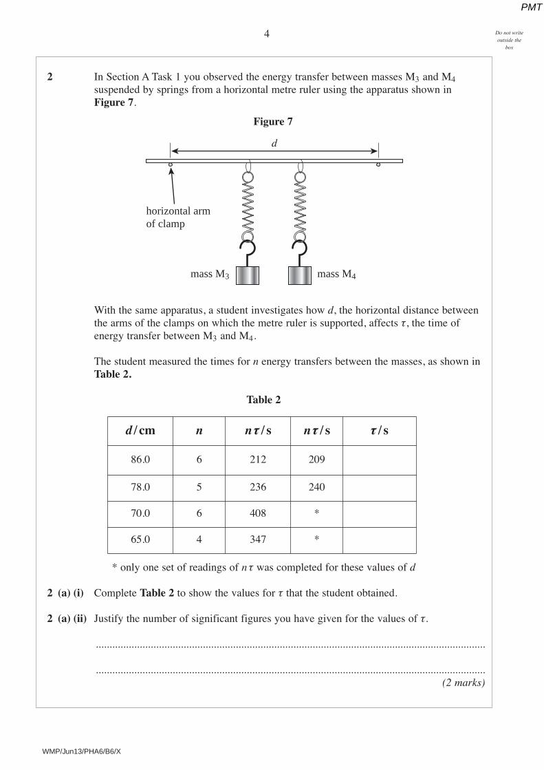
2 In Section A Task 1 you observed the energy transfer between masses M3 and M4suspended by springs from a horizontal metre ruler using the apparatus shown inFigure 7.
Figure 7
With the same apparatus, a student investigates how d, the horizontal distance betweenthe arms of the clamps on which the metre ruler is supported, affects τ, the time ofenergy transfer between M3 and M4.
The student measured the times for n energy transfers between the masses, as shown inTable 2.
Table 2
* only one set of readings of n τ was completed for these values of d
2 (a) (i) Complete Table 2 to show the values for τ that the student obtained.
2 (a) (ii) Justify the number of significant figures you have given for the values of τ.
..............................................................................................................................................
..............................................................................................................................................(2 marks)
horizontal armof clamp
d
mass M3 mass M4
d / cm n nτ / s nτ / s τ / s
86.0 6 212 209
78.0 5 236 240
70.0 6 408 *
65.0 4 347 *
PMT

5
Turn over �WMP/Jun13/PHA6/B6/X
Do not writeoutside the
box
2 (b) The student claimed that these results showed that τ was directly proportional to ––– .
Analyse the data in Table 2 to show whether the student’s claim is correct.
.............................................................................................................................................
.............................................................................................................................................
.............................................................................................................................................
.............................................................................................................................................
.............................................................................................................................................
.............................................................................................................................................
.............................................................................................................................................
.............................................................................................................................................(2 marks)
2 (c) Suggest three valid control variables for the experiment.
1 ..........................................................................................................................................
2 ..........................................................................................................................................
3 ..........................................................................................................................................(1 mark)
THE QUESTION IS CONTINUED ON THE NEXT PAGE
1
d2
PMT

WMP/Jun13/PHA6/B6/X
6 Do not writeoutside the
box
2 (d) In a different experiment to illustrate energy transfer between oscillators, three barmagnets are arranged as shown in Figure 8.
Figure 8
Magnets B and C are balanced on one edge using the repulsion produced by magnet A,the paper below providing friction to prevent B and C slipping.When B is set oscillating about the point of contact with the paper, the oscillatingmotion is transferred within a few cycles to C, and then back again, as in yourexperiment with masses M3 and M4.
A student uses a motion sensor and a data logger to record the motion of magnet B; thedata are then exported to a computer and analysed using a spreadsheet.Figure 9 is based on 25000 measurements that are transferred to the data logger in 10 seconds and shows how the displacement, y, of the moving end of magnet B, varieswith time, t.
Figure 9
magnet A
magnet B magnet C
sheet of paper to preventmagnets B and C slipping
magnet B is set in oscillation oscillating motion is transferred to magnet C
–50 2 4 6
t / s108
–3
–1
3
2
1
5
y / mm
–4
–2
0
4
PMT

7
Turn over �WMP/Jun13/PHA6/B6/X
Do not writeoutside the
box
9
2 (d) (i) What was the sample rate of the data logger when the data displayed in Figure 9 wasbeing recorded?
sample rate = ......................................................................................................................
The sample rate is then changed so that 25 000 measurements are transferred to thedata logger in 250 seconds. These results are displayed in Figure 10.
Figure 10
2 (d) (ii) If τ = the time for energy transfer from magnet B to magnet C and back again to B,and T = the period of oscillations of magnet B, use Figure 9 and Figure 10 to
determine ––.
You may assume that in both Figure 9 and 10, y has just reached a maximum valueat t = 0.
.............................................................................................................................................
.............................................................................................................................................
.............................................................................................................................................
.............................................................................................................................................
–– = .............................................................................................(4 marks)
–50
t / s
–3
–1
3
2
1
5
y / mm
–4
–2
0
4
50 100 150 250200
τT
τT
PMT

8
WMP/Jun13/PHA6/B6/X
Do not writeoutside the
box
3 In Section A Task 1 you used a compass to investigate how the magnetic fluxdensity varies between two bar magnets. One magnet was positioned on a metre ruler,aligned east-west, and the other on a half-metre ruler, aligned north-south.A student, performing this experiment, sees that when the magnet on the half-metreruler is removed the compass needle rotates through an angle θ, as shown in Figure 11.The student notices that when the remaining magnet is moved along the metre ruler sothat the distance x defined in Figure 11, is reduced, θ increases.
Figure 11
θ
x
N
S
W E
bar magnet
compass
metre ruler
half-metreruler
N
PMT

9
WMP/Jun13/PHA6/B6/X
Do not writeoutside the
box
A teacher explains that B, the magnetic flux density due to the bar magnet at theplotting compass, is given by B = B0 tan θ.B0 is the horizontal component of the ambient magnetic flux density (ie due to thesurroundings) and is known to be 1.8 × 10⁻⁵ T.
3 (a) Describe how the student could investigate how B varies with x, the distance along themetre ruler from the end of the magnet to the centre of the compass.Your answer should:l explain how the student should make the necessary measurements to determine
B and x; you may wish to add detail to Figure 11 to illustrate this part of your answer
l explain any relevant procedure that will reduce systematic error in the resultsfor B
l explain how the measurements will be used to determine how B varies with x.
.............................................................................................................................................
.............................................................................................................................................
.............................................................................................................................................
.............................................................................................................................................
.............................................................................................................................................
.............................................................................................................................................
.............................................................................................................................................
.............................................................................................................................................
.............................................................................................................................................
.............................................................................................................................................
.............................................................................................................................................
.............................................................................................................................................
.............................................................................................................................................
.............................................................................................................................................(3 marks)
THE QUESTION IS CONTINUED ON THE NEXT PAGE
Turn over �
PMT

10
WMP/Jun13/PHA6/B6/X
Do not writeoutside the
box
3 (b) The teacher shows the student an instrument called a deflection magnetometer andsuggests that this could be used in place of the compass to reduce uncertainty in themeasurement of θ.
A deflection magnetometer, as seen from above, is shown in Figure 12 and consistsof a magnet pivoted at the centre of a rotary scale. A long pointer is mounted at rightangles to the magnet and a mirror is set into the dial. A plotting compass is shown tothe same scale so a comparison can be made with the size of the magnetometer.
Figure 12
State and explain two features of the design of the magnetometer that help to reduceuncertainty in the measurement of θ.
first feature:
.............................................................................................................................................
.............................................................................................................................................
.............................................................................................................................................
second feature:
.............................................................................................................................................
.............................................................................................................................................
.............................................................................................................................................(3 marks)
END OF QUESTIONS
0340
320
300
280
260
240
220
200 180
160
140
120
100
80
60
40
20
compass shownto same scale
mirror set intothe dial of themagnetometer
needle
magnet
6
PMT

11
WMP/Jun13/PHA6/B6/X
There are no questions printed on this page
DO NOT WRITE ON THIS PAGEANSWER IN THE SPACES PROVIDED
PMT

12
Copyright © 2013 AQA and its licensors. All rights reserved.
WMP/Jun13/PHA6/B6/X
There are no questions printed on this page
DO NOT WRITE ON THIS PAGEANSWER IN THE SPACES PROVIDED
PMT