piaggio service
DESCRIPTION
service manualTRANSCRIPT

i
Technical Notes and Workshop Reference.This reference file has been built up over the last twelve years at Piaggio Ltd,To help with fault finding, assembly understanding and to clarify and expandon technical information contained in Service Station Manuals and partscatalogues supplied from Italy.
Most of these pages have been created to help answer often asked questionsI hope you find it useful.
We must ask you to consider this information as classified and therefore donot pass it on to anyone for any reason. I will be very disappointed if anythinghere turns up in the press or is quoted by customers. This information iscontinually being updated so please check the Piaggio Web site occasionallyto see if there are new or updated pages available.
If you find an amended page please destroy the original to avoid anyconfusion.If you find any mistakes or you feel that the information could be betterpresented or improved please contact me at Piaggio Ltd, after sales.
DISCLAIMER.The information supplied here is accurate to the best of my knowledge but no guarantee isgiven as to the accuracy or suitability of this information. This information should always beused in conjunction with the relevant Piaggio manuals.Piaggio Ltd, reserves the right to amend or withdraw any information contained herewithout prior notification.
Piaggio Ltd, its employees and agents can not be held responsible for any inaccuracies oromissions in this information. Nor can they be held liable for any consequence of using thisinformation.
David ChampionPiaggio Ltd.
Technical Services© Piaggio Ltd 1995 - 2006

ii
Technical / After sales contacts:
For any After Sales problems or questions, your first contact should be yourRegional After Sales Manager.
Benjy Straw - Technical Services Manager020 7401 4323. [email protected]
Gene Dalzell - Regional after sales manager, Midlands and North07050 263036. [email protected]
Paul Balsillie - Regional after sales manager, Southern07050 263039. [email protected]
Mike Edwards - Warranty Management020 7401 [email protected] for warranty authorisation: 020 7401 4321
David Champion - Technical information and advice020 7401 4325. [email protected]
Adam Roylance - Technical & After Sales Training07881 786478. [email protected]
Sebnem Umman - Spare Parts and Accessories Manager020 7401 4329. [email protected]
Technical department Fax: 020 7401 4321
PLEASE MAKE SURE THAT YOU CONTACT THERIGHT PERSON

3
Chapter 12 Stroke Auto engines
1. 50 / 80cc Charging early type2. 50 / 80cc Charging later type2a. NRG Charging & Gauges2b. NRG Power Instrument connection3. 50cc 2t Ignition4. 125 & 180cc Charging / Ignition5. 125 & 180cc Indicator circuit6. 125 / 180cc Ignition7. Runner 125 / 180cc 2t Fuses8. Diesis 100 Ignition / Charging9. Purejet 50 Charging / Ignition10. Purejet 50 Indicators / Oil Check11. Fly 50 Charging / Carb heaterChapter 2
Leader / Quasar engines.1. B125 / 200 Ignition / Charging2. B125 Notes3. B125 Fuse explanation4. DNA 125 / 180 Ign. / Charging5. DNA 125 / 180 Switch Wiring6. ET4 125 Ignition / Charging7. Hexagon GTX Ignition / Charging8. Runner VX / VXR Ign./Charging9. X9 125 / 180 Ignition / Charging9a. X9 125 Indicator Wiring10. Zip 125 Ignition / Charging11. General notes12. Immobiliser System explanation13. Vespa GT 125 / 200 Ignition / Charging14. Vespa GT Fuses15. Skipper ST Ignition / Charging16. Skipper ST Fuses17. Skipper ST replacement instrument panel18. X9 250 Evo Ignition / Charging19. Fly 125 Ignition / Charging19a Fly 125 Instrument panel connections20. X8 125 / 200 Ignition / Charging21. X8 Seat & Trunk Release22. X8 125 / 200 Fuse ExplanationChapter 3
4 Stroke (Non Leader) engines1. Coguar 125 Ignition / Charging2. ET4 (ZAPM04) Early Charging3. ET4 (ZAPM04) Late Charging4. ET4 (ZAPM04) Immobiliser Notes5. Hexagon GTX 250 Ign./ Charging6. Liberty 125(non Leader) Charging7. X9 250 Ignition / Charging8. X9 250 Notes9. X9 250 Fuse Explanation10. 50cc 4 stroke Ignition / Charging11. 50cc 4 stroke Restriction NotesChapter 4
2 Stroke Manual engines.1. H@k / GSM Ignition / Charging2. H@K / GSM Notes3. H@K / GSM Wiring Diagram4. Vespa PX Ignition / Charging5. Vespa PX Start Permissive Circuit6. Vespa PX Indicator Circuit7. Vespa T5 Horn circuit8. Gilera RCR 50 Ignition / Charging9. Gilera RCR Notes
Chapter 5Electrical General
1. X9 Range General Notes2. X9 Range. Under the front Panel3. Stator Coil Values - Quick Ref.4. Auto Choke Operation5. Fuel Gauge Circuit6. Digital Instrument Display Notes7. Remote Seat Release8. Setting the 2 button Digital ClockChapter 6
Fuel Systems1. Typhoon 80 / 125 Fuel System2. DNA Fuel Systems3. Hexagon (EXS1T) Fuel System4. Pumped Fuel Systems5. Vespa PX Fuel TapChapter 7
Mechanical1. Fitting Main Bearings. All 2t autos.2. Vespa PX Clutch assy.3. Piston & Small End Sizes4. Up Side Down Forks5. Spark Plug List6. Oil List7. Tyres / Wheels Piaggio7a. Tyres / Wheels Vespa8. Tyres / Wheels Gilera9. Keys Gilera10. Keys General11. De-Restriction Notes12. Chassis Number Location13. Quick Reference Guide14. Service Limit ListChapter 8
Injected Vehicles1. X9 500 ignition2. X9 500 lighting3. X9 500 Centre Stand wiring4. Nexus 500 Instrument panel connectionsChapter 9
Tech Tips Collection1. Tech Tips 012. Tech Tips 023. Tech Tips 034. Tech Tips 045. Tech Tips 05

Chapter 1
Electrical systems
Two Stroke Auto engines
1. 50 & 80cc Charging, early type
2. 50 & 80cc Charging, later type
2a. NRG / Zip Cat Charging & Gauges
2b. NRG Power instruments
3. 50 & 80cc Ignition
4. 125 & 180cc Charging / Ignition
5. 125 & 180cc Indicator circuits
6. 125 & 180cc Ignition
7. Runner 125 / 180 2t Fuses
8. Diesis 100 Ignition / Charging
9. Purejet 50 Charging / Ignition
10. Purejet 50 Indicators / Oil check
11. Fly 50 Charging / Carb heater

Chapter 2
Electrical Systems
LEADER / QUASAR Engines
1. B125 / 200 Ignition / Charging
2. B125 Notes
3. B125 Fuse Explanation
4. DNA 125 / 180 Ign. / Charging
5. DNA 125 / 180 Switch Wiring
6. ET4 125 Ignition / Charging
7. Hexagon GTX Ign. / Charging
8. Runner VX / VXR Ign. / Charging
9. X9 125 / 180 Ignition / Charging
9a. X9 125 Indicator Wiring
10. Zip 125 Ignition / Charging
11. Leader General Notes
12. Immobiliser Notes
13. Vespa GT 125 / 200 Ignition / Charging
14. Vespa GT 125 / 200 Fuses
15. Skipper ST Ignition / Charging
16. Skipper ST Fuses
17. Skipper ST replacement instrument panel
18. X9 250 Evo Ignition / Charging
19. Fly 125 Ignition / Charging
19a. Fly 125 Instrument connections.
20. X8 125 / 200 Ignition / Charging
21. X8 Seat & Trunk release
22. X8 125 Fuse explanation

Chapter 3
Electrical Systems
Four Stroke (Non Leader)
1. Coguar 125 Ignition / Charging
2. ET4 (ZAPM04) Early Charging
3. ET4 (ZAPM04) Late Charging
4. ET4 (ZAPM04) Immobiliser Notes
5. Hexagon GTX 250 Ign./ Charging
6. Liberty 125 (non Leader) Charging
7. X9 250 Ignition / Charging
8. X9 250 Notes
9. X9 250 Fuse Explanation
10. 50cc 4 stroke Ignition / Charging
11. 50cc 4 stroke Restriction Notes

Chapter 4
Electrical Systems
Two StrokeManual Engines
1. H@k / GSM Ignition / Charging
2. H@K / GSM Notes
3. H@K / GSM Wiring Diagram
4. Vespa PX Ignition / Charging
5. Vespa PX Start Permissive Circuit
6. Vespa PX Indicator Circuit
7. Vespa T5 Horn circuit
8. Gilera RCR 50 Ignition / Charging
9. Gilera RCR 50 Notes

Chapter 5
Electrical Systems
General
1. X9 Range General Notes
2. X9 Range. Under the front Panel
3. Stator Coil Values - Quick Ref.
4. Auto Choke Operation
5. Fuel Gauge Circuit
6. Digital Instrument Display Notes
7. Remote Seat Release
Chapter 6
Fuel Systems
1. Typhoon 80 / 125 Fuel System
2. DNA Fuel Systems
3. Hexagon (EXS1T) Fuel System
4. Pumped Fuel Systems
5. Vespa PX Fuel Tap

Chapter 7
Mechanical Systems
1. Fitting Main Bearings. All 2t autos.
2. Vespa PX Clutch assy.
3. Piston & Small End Sizes
4. Up Side Down Forks
5. Spark Plug List
6. Oil List
7. Tyres / Wheels Piaggio
7a. Tyres / Wheels Vespa
8. Tyres / Wheels Gilera
9. Keys Gilera
10. Keys General
11. De-Restriction Notes
12. Chassis Number Location
13. Quick Reference Guide
14. Service Limit List

Chapter 8
Injected Vehicles
1. X9 500 Charging wiring
2. X9 500 Ignition Wiring
3. X9 500 Centre Stand Wiring
4. Nexus 500 Instruments Wiring
Chapter 9
Tech Tips
A collection of the
Tech Tips
previously published
on the Piaggio Portal
01
02
03
04
05

30/09/2005Piaggio Ltd. 5 pin regulator
50 / 80cc 2T Charging (early vehicles)
BATTERY12v
+
CHOKE UNIT
7.5 ampFUSE
IGNITIONSWITCH
YELLOW
BLUE
GREY / BLUE
RED
GREY
DC SERVICESBrake light
Horn
RED
BLUE
WHITE
* This diagram shows the early 50cc and 80cc two stroke wiring using a five pin connector on the rectifier / regulator. Refer to the separate diagram for later circuit using an eight pin rectifier / regulator.* RECOGNISE THIS CIRCUIT: If the oil warning light comes on when the starter button is pressed.* Two completely separate circuits for AC & DC.
AC is full wave and regulatedDC is half wave rectified and regulated
* If voltage at the B+ terminal falls below 8v (approx) the DC rectifier / regulator will not function so there will be no output from the alternator on the DC circuit.* Separate indicator relay.* The choke is supplied with 12v AC when the engine is running .TESTS.1. Grey / Blue to earth = 25-30v AC stator un-plugged and engine at 2000rpm.2. Yellow to Blue = 26-30v AC stator and battery disconnected and engine at 2000 rpm.3. Ammeter between red wire and battery positive = 1.5-2 amp with fully charged battery and engine at 2000 rpmNOTES.Engine must be earthed to the chassis / battery. Lack of this connection will affect the AC circuit and starter motorbut not the DC circuit or ignition circuit.
1
3
WH
ITE
BLA
CK
YE
LLO
W
GR
EY
/ B
LUE
RECTIFIER&
REGULATOR
B+GAA
REGULATOR
2
GR
EY
ACSERVICESHead lightTail light
Instruments
12v 4ah - 50cc12v 5ah - 80cc
1 - 1
OFF
ON
RED

30/12/2005Piaggio Ltd. 8 pin regulator
50 / 80cc 2T charging
BATTERY12v
+
CHOKE UNIT
7.5 ampFUSE
ACSERVICES
YELLOW
BLUE
GREY / BLUE
RED / WHITE
GREY
DC SERVICESBrake light
Horn
RED
BLUEWHITE
* This diagram shows the later 50cc and 80cc two stroke wiring using an eight pin connector on the rectifier / regulator. Refer to the separate diagram for earlier circuit using a five pin rectifier / regulator.* RECOGNISE THIS CIRCUIT: If the oil warning light comes on for 15 seconds when ignition is turned on.* Two completely separate circuits for AC & DC.* Eight pin rectifier / regulator incorporates the indicator relay and oil light check function.* The choke is supplied with 12v AC when the engine is running .TESTS.1. Grey / Blue to earth = 25-30v AC stator un-plugged and engine at 2000rpm.2. Yellow to Blue = 26-30v AC stator and battery disconnected and engine at 2000 rpm.3. Ammeter between red wire and battery positive = 1.5-2 amp with fully charged battery and engine at 2000 rpm4. Output to the indicator switch will be a 12v DC pulse with ignition on.NOTES.* Engine must be earthed to the chassis / battery. Lack of this connection will affect the AC circuit and starter motor but not the DC circuit or ignition circuit.* Rectifier regulator pin 3 & 4 are both out puts from the timer so the wire could be connected to either pin.
1
3
NOTUSED
see noteTO INDICATOR
SWITCH
Head lightTail light
Instruments
WH
ITE
BLUE / BLACKBLA
CK
YELLOW
4
GR
EY
/ BL
UE
4321 5 6 7 8
REGULATORRECTIFIER
®ULATOR
2
OILWARNING
LIGHT OIL TANKSENDER
1-2
IGNITION SWITCH
OFF
ON
OILLIGHTTIMER

GREY
DC SERVICESBrake light
Horn
TO INDICATORSWITCH
BLU
E /
RE
D
BLUE / BLACK
BLA
CK
YELLOW
GR
EY
/ BL
UE
CHOKE UNIT
ACSERVICESHead lightTail light
Instruments
RECTIFIER&
REGULATOR
4321 5 6 7 8
REGULATOR
TIMER
YE
LLO
W /
GR
EEN
WH
ITE
/ V
IOLE
T
BLUE / RED
30/09/2005Piaggio Ltd. 8 pin regulator
NRG (up to Mc3) & ZIP Cat. Charging & Guages
BATTERY12v
+
7.5 ampFUSE
IGNITIONSWITCH
YELLOW
BLUE
GREY / BLUE
RED / WHITERED
BLUE WHITE
OILWARNING
LIGHT
1 - 2 a
FUELWARNING
LIGHT
FUEL GUAGENRG only
FUELSENDER
UNIT
WH
ITE
/ V
IOLE
T
WH
ITE
YE
LLO
W /
GR
EEN
WH
ITE
/ G
RE
EN
The NRG (up to Mc3) / Zip Cat wiring is very similar to other 50 / 80 scooters.Refer to page 1-2 (50 / 80 Charging) and page 1-3 (50cc 2t Ignition) for other information.
TESTS1. Grey / Blue to earth = 25-30v AC stator un-plugged and engine at 2000rpm.2. Yellow to Blue = 26-30v AC stator and battery disconnected and engine at 2000 rpm.3. Ammeter between red wire and battery positive = 1.5-2 amp with fully charged battery and engine at 2000 rpm.4. Output to the indicator switch will be a 12v DC pulse with ignition on.5. 12v DC for 15 seconds after ignition is turned on With sender unplugged.NOTES.* Wires at terminals 3 & 4 could be reversed.* Engine must be earthed to the chassis / battery. Lack of this connection will affect the AC circuit and starter motor but not the DC circuit or ignition circuit.
1
4
32
OIL TANKSENDER
BR
OW
N
BLUE / REDWHITE
BR
OW
NW
HIT
E /
VIO
LET
5
5
FUEL

1-2b
- NRG POWER Digital Instrument Panel Connector -
Multi pin connector on rear of instrument panel
PIN WIRE COLOUR CONNECTION1 Blue / Red BlR Battery Positive. Permanent Live +2 White B Ignition Switch. Switched Live +3 Black N Earth -4 Grey / Black GrN Wheel Speed Sender. Earth -5 Red Rs Wheel Speed Sender. Power +6 Light Blue Az Wheel Speed Sender. Signal7 Yellow / Black GN Instrument lights8 Black / Orange NAr ?9 - - Not used10 Green V Rev counter signal. 100> volts AC
*11* Yellow / Red GR Coolant temperature. Signal out to gauge, gauge earth's12 White / Green BV Fuel gauge. 12v out to sender, sender earth's13 Purple Vi High beam14 White / Blue BBl Turn signal right. 12v in to bulb when right turn selected15 Pink R Turn signal left. 12v in to bulb when left turn selected16 White / Purple BVi Low two stoke oil warning light. Power in from sender17 Yellow / Green GV Low fuel light. Power out to gauge, gauge earth's18 - - Not used19 - - Not used20 - - Not used
* Pin 11 is only used on the liquid cooled engine *.
1 2 3 4 5 6 7 8 9 10
11 12 13 14 15 16 17 18 19 20

25/08/05Piaggio Ltd Piaggio Ltd
50cc 2t Ignition
GREEN
GREEN
GREEN
IGNITION SWITCH
IGNITION PICK UP
Champion NR2CNGK BR9ES
RED
WHITE
TESTS1. UNPLUG STATOR and CDI. GREEN WIRE SHOULD BEEARTHED WHEN IGNITION IS "OFF"2. CHECK CHARGING COIL. GREEN TO WHITE = 980 ± 50 ohms.3. CHECK TRIGGER COIL. RED TO WHITE = 88 ± 5 ohms.4. SPARK PLUG NRG's are now supplied with Champion N1C plugs The NGK equlivilent is B10ES. This plug is very cold running and may not suit all riders. If you find that a machine is fouling plugs try fitting an NGK B9ES.
COMMON EARTHFOR
INSTRUMENT PANNEL
1
REV COUNTER
STATOR
This circuit could apply to any twist & go 50cc two stroke with or without a rev counter
OFF
ON
CDI / COILunit
CDI / COILunit
IgnitionCharging Coil
NOTES
White wire is a common, dedicated earth for the ignition system.If the engine earth strap was missing the engine would run but you may have problems with the CDI unit failing because theelectrical system may try to use the white wire as its earth connection.
Green wire will have 150-200v AC when engine is running.
Ignition timing ix fixed, i.e. there is no automatic advance / retard.
GREEN
WHITE
RED
1-3

11/09/2003Piaggio Ltd
125 & 180cc 2t charging / IgnitionTyphoon, Skipper, Hexagon, Runner
STATOR
BATTERY12v
+
CDIUnit
IGNITIONPICK UP
FUSE
CHARGEWARNING
LIGHT
RED
RED
RED
RED
YELLOW
YELLOW
GREEN
WHITEBROWN
PURPLE
GR
EY
WHITE
GREEN
NOTES* Choke and Carb' heater will have a supply with ignition turned on but the rectifier / regulator will only complete the circuit to earth when it detects a charge. I.e. the engine is running.* The Charge warning light goes out when the engine is charging because +12v D.C. is applied to both sides of the bulb, not because the circuit is broken.* On water cooled engines the cooling fan is always live, the thermostat switch is on the earth side. So a battery going flat could be caused by a faulty fan or fan switch.* The starter solenoid is always live so is a possible cause of a battery going flatTESTS1. Stator Output.
Yellow to Yellow 27 - 31 v A.C.@ 2000 rpm. Unplug regulator.Green - White 50 -150 ohm. Runner & Hexagon.(Stator un-plugged)
100 -160 ohm. Skipper & Typhoon.(Stator un-plugged)Red - Brown 90 -140 ohm. All models. (Stator un-plugged)
2. Charging.Between Red & Battery positive: >< 8.5 amps@ 2000 rpm with a fully
charged battery (13.5v)3. Battery voltage must be present at terminal "C" with ignition on or the output from terminal B will be unregulated. Battery will boil, bulbs will blow etc.MAIN FUSE:
Runner (ZAPM07 / 08) 25 amp.Hexagon (EXS1T & ZAPM05 / 06) 25 amp.Typhoon (ZAPM02) 15 amp.Skipper (CSM1T) 7.5 amp.
GGBL CA
ChokeControl
DCRectifier
RegulatorOut put only whencharging
RED
WH
ITE
BR
OW
N
GR
EY
YELL
OW
YELL
OW
COOLING FANON
WATER COOLEDMODELS
Choke Unit Carb. Heater
OFF
ON
IGNITION SWITCH
SUPPLYTO
SYSTEMS
1-4

INDICATOR SWITCH
ABOVE. Vehicles 1999> Cirduit with oil check light that comes on when ignition is switched on.
Refer to the Service Station Manual. Also Technical Notes 2/99 and 3/99.
BELOW. Vehicles <1999 Circuit with oil check light that comes on when brake is held on and starterbutton is pressed.
BLACK
BEL
S
B
LOW OILWARNINGSWITCH
STOP SWITCH
BLUE / RED
+ 12V DC
STARTERSWITCH
STARTERRELAY
OIL WARNINGLAMP
11/09/2003Piaggio Ltd Piaggio Ltd
125 / 180 Two Stroke INDICATOR CIRCUIT
YELLOW
BLACK / BLUE
YELLOW
INDICATORRELAY
1-5
BLACK / BLUE
YELLOW
L
BSTOP SWITCH
LOW OILWARNINGSWITCH
GREEN / BLACK
OIL WARNINGLAMP
STARTER SWITCH
DIODE
INDICATOR SWITCH
+ 12V DC
STARTERRELAY
WHITE / REDINDICATORRELAY
WHITE / RED

11/09/2003Piaggio Ltd.Hexagon LX / LXTRunner FX / FXRSkipper & Typhoon 125
125 / 180 2T Ignition
R B W G V
CDI UNIT
OFF
ON
STATOR
RED
BROWN
WHITE
GREEN BLACK
GREEN
PURPLE
IGNITION SWITCH
IGNITION TIMING IS CDI CONTROLLED Not adjustable
Skipper and Typhoon:Ignition is fixed at 19 degrees.Hexagon and Runner:Two position ignition (not progressive).9 deg @ 1500+ rpm. Then 22 deg @ 7500+
* The ignition circuit is a separate self-contained circuit with no fuses and no connection to the other electrical circuits on the vehicle. It has a separate charging coil in the stator (Green & White wires).
* The ignition switch contacts are OPEN when the engine is RUNNING. Contacts are CLOSED when switch is turned OFF, this allows the system to discharge to earth. When fault finding, if there is no spark then check the "green" and "purple" wires to see if there is a "leak" to earth. Unplug stator & CDI, check green to earth: Ignition on = no continuity. Ignition off = continuity.
* A "Resistor" type spark plug and a resistor plug cap should always be fitted.
* This circuit does not require the engine to chassis earth. But if that earth lead is missing it is possible that trying to use the starter motor could force excess current through the CDI and damage it. Always prove you have a good engine to chassis earth connection.
NOTES.
1-6
Purple - EarthHT Primary
HT lead - EarthHT Secondary
Meter between >To test >
Hexagon LX / LXTRunner FX / FXRSkipper / Typhoon 125
Red - BrownPick - up Coil90 - 140 ohm90 - 140 ohm90 - 140 ohm
White - GreenCharge Coil
50 - 100 ohm50 - 100 ohm100 - 160 ohm
STATOR TEST VALUES. Stator un-plugged
0.5 0.025 ohm+0.5 0.025 ohm+0.5 0.025 ohm+
4.8 0.25 k ohm+4.8 0.25 k ohm+4.8 0.25 k ohm+

1-7Piaggio Ltd. May 2000
FUSE EXPLANATIONRunner FX 125 & FXR 180
Circuits protected by each fuse.
1. Head light flash (passing light).2. Indicators. Brake light. Oil indicator. Electric start relay. Temp gauge. Fuel gauge. Horn.
Choke.3. Headlight relay. Town light. Rear light (lighting switch)4. Both headlights (power)
Notes.• Ignition circuit is completely separate and self powered. It does not have any fuses.• The cooling fan is permanently live and is protected by the main 25 amp fuse.• The starter motor supply is not fused.
Relation between lighting and the fuses.
WHITE
WHITE
WHITE
WHITE / RED
GREY / BLACK
GREY RED
RED / BLACK
10 amp 4
7.5 amp 1
7.5 amp 2
10 amp 3
+12v whenignition is ON
Permanent +12vvia 25 amp fuse
HeadlightRelay
LightingSwitch
Head LightFlash
High / LowSwitchLow Beam
High Beam1
4
3
From Fuse#

Rectifier /Regulator
11/06/02Piaggio Ltd. Derbi engine
DIESIS 100 Charging / Ignition
Red4
amp
White / Red
Yellow
Earth wires are - Yellow / green.Yellow wire is AC supply.Red / Blue wire is DC supply.Engine earth is very important.Carb heater is driven by AC power via a thermostat.No separate Ignition pick up, CDI is triggered by the AC wave.Ignition is earthed to stop the engine.
NGKB9 ES
Yellow / Green
Yellow / Green
Yellow / Green
Green / Black
Orange
PinkWhite
Red / Blue
Yellow
Green / Black
Red
Red
Gre
en /
Blac
k
Yel
low
/ G
reen
AC Supply
DC Supply
LEFT
OFF
RIGHT
Indicators
Yellow / White
White / Red
Ignition SwitchLOCK
OFF
ON
GreenOrangeBlack Red / White
Black / Red
Carb. Heater
BATTERY12v4ah
+Red
Tostarter
solenoid
TESTS.Stator: Yellow - Earth = min 25 v AC. White / Red - Earth = min 30 v AC. Engine at mid rpm.
Yellow - Earth = 0.9 ohm + 0.2. White / Red - Earth = 1.1ohm + 0.2. Stator un-plugged.Black / Red - Earth = 238 ohm + 10%. Stator un-plugged.
Regulator: Yellow - Earth = 13.5 + 0.5 v AC. White / Red - Earth = 13.5 + 1.0 v DC. Engine at mid rpm.Ignition: HT coil secondary resistance = 5 - 6 K ohm. Unit un-plugged.
+ 5o C
Thermostat
Black
Black
1-8
IndicatorRelay
Rectifier&
RegulatorRegulator
Orange - Indicator switch
Yellow - AC circuit
Red / Blue - DC supply
White / Red - Stator
Red - Battery
Explanation of Rectifier / regulator wiring

02/09/2003Piaggio Ltd. GILERA RUNNER
PUREJET 50 IGNITION / CHARGE
OFF
ON
BATTERY12v
+
~ ~ ~ +
YELLOW
YELLOWYELLOW
BLUE
BLUE
RED
RED
ORANGERED / BLUE
BLACK / VIOLET
1 2 3 4 5 6 7 8 9 10 11 12 13 14 15 16 17 18 19 20 21 22
ECU
BLU
E
RED
BLAC
K / V
IOLE
T
OR
ANG
E
SYSTEM NOTES.* 3 Phase AC.* Permanent live battery feed to Rectifier, ECU, HT Coil (blue wire). Any of these could drain the battery if they were faulty.* HT Coil is trigered by the BLACK / VIOLET wire being earthed via the ECU.
TESTS:Stator: Disconected. Any yellow to any yellow = 0.7 - 0.9 ohm. Any yellow to earth = No continuity Pick Up coil value is not quoted.Rectifier / Regulator: With a charged battery the possible voltage must not exceed 15.2 volts.
HT COIL
IGNITION SWITCH
RECTIFIER / REGULATOR
STATOR
PICK UP
FUSE
15 amp
15 amp ChampionRG6YCA
BLUE
BLUE
BLU
E
BROWN
BRO
WN
To starterrelay
1-9

12/01/2004Piaggio Ltd. Runner
Purejet 50 Turn Signals & Oil check
BATTERY12v
+
ON
Yellow
White
Ora
nge
BESL
Black
White
Yellow
Black / Blue
Red
/ B
lue
Red
15 ampFuse's inBattery
Compartment
Yellow
7.5 amp Fuse'sin HornCompartment
Grey / Red
Blue
White / Red
Oil TankSender
Low OilWarning
Light
TurnIndicatorSwitch
Rig
ht T
urn
Indi
cato
rs
Pink
Pink White / Blue
White / Blue
Ignition Switch
Black / Blue
IndicatorControl Unit
* The low oil warning light check function is controlled by the indicator relay.* The oil check light should come on for 15 seconds when the ignition is first turned on.* If the system fails: first check the 7.5 amp fuse located under the front grill (horn) panel.
Whi
te
1 - 10
Left
Turn
Indi
cato
rs
OFF
LEFT
RIGHT
LOW

13/12/2005Piaggio Ltd. 2 stroke engine
Fly 50 & Vespa LX 50 charging & carb heater
BATTERY12v 4ah
+
CHOKE UNIT
7.5 ampFUSE
IGNITIONSWITCH
YELLOW
BLUE
GREY / BLUE
RED / BLUE
YELLOW / BLACK
DC SERVICESBrake light
Horn
RED
BLUE
WHITE
This diagram shows the Fly 50 & Vespa LX 50 two stroke wiring, it is basically the same as other 50 two strokesbut there are a few slight variations including the electric carb heater.TESTS.
Stator out put. Grey / Blue to earth = 25-30v AC stator un-plugged and engine at 2000rpm.Stator out put. Yellow to Blue = 26-30v AC stator un-plugged and engine at 2000 rpm.Ammeter between red wire and battery positive = 1.5-2 amp with fully charged battery and engine at 2000rpmOutput to the indicator switch will be a 12v DC pulse with ignition on.
NOTES.The carburettor heater is DC powered but the controller is activated by AC so it will only turn the heater onwhen the engine is running (AC output is detected).The choke is AC powered as normal. It is not controlled by the Carb. heater controller.Engine must be earthed to the chassis / battery. Lack of this connection will affect the AC circuit and startermotor but not the DC circuit or ignition circuit.
1
3
NOTUSED
TO INDICATORSWITCH
WH
ITE
/ R
ED
BLU
E /
BLA
CK
BLA
CK
YE
LLO
W
4
GREY / BLUE
2
OILWARNING
LIGHT
OIL TANKSENDER
1-11
OFF
ON
RE
D /
GR
EE
N
ORANGE
WH
ITE
RECTIFIER&
REGULATOR
4321 5 6 7 8
REGULATOR
OILLIGHTTIMER
GREY / BLUE
ACSERVICESHead lightTail light
Instruments
YELLOW / BLACK
YELLOW / BLACK
CARB. HEATER Lt. BLUE
ORANGE / BLACK
WHITEWHITE
Carburettorheatercontrol
AC

3 2 18 7 6 5 4
Rectifier /Regulatorp/n: 82501R
25/08/05Piaggio Ltd. With IMMOBILISER
B 125 / 200 ignition / charging
Red
White / Black
Yellow
IgnitionPick up
CDI / Immobiliser
IgnitionSwitch
HT Coil
White
Purple
Red / Black
Black
White
CoolingFan Fan
Switch
Red / Black
Green
White / Green or Light Blue
White
Red / Black
Lt. Blue
White /Green
G
Choke Unit White
White /OrangeWhite
Lt. Blue
Black / BlueIndicatorSwitch
Yellow / Blue
Red / Blue
Red / Black
Green
Orange
Emergency Stop
Green / Blue
OFF
1
2
Seat Lock Seat ReleasePush Button
Blue
White / BlueWhite
Blue
Green
Ignition Relay
4 amp
BATTERY12v
10ah
+
CR 9EB
Side StandSwitch
ImmobiliserLED
StandWarning
Blue / Black
CDI CONNECTIONS1. BLUE / BLACK - INDICATOR SWITCH SUPPLY2. GREEN - INPUT FROM IGNITION PICK UP3. PURPLE - TO HT COIL4. RED / BLACK - 12v PERMANENT LIVE5. WHITE / GREEN - SUPPLY FROM IGNITION SWITCH6. YELLOW / BLUE - IMMOBILISER LED7. WHITE / BLACK - CHOKE CONTROL8. BLACK - EARTH
STOP
RUN
Down
UP
2-1
15 4
Blu
e
Red
/ B
lack
Red
/ B
lue
15 15
White / Black
Yellow / Blue
White / Green
Red / Black
antenna

2-2
B 125 / 200 NOTES
The notes should be used in conjunction with Service Station Manual 594845 andthe notes “B 125 ignition / charging” and “B 125 Fuse Explanation”
1. Seat has electric release. Only works when ignition switch is in the “off”position.If seat lock fails to operate:
Check fuse “7” in rear fuse box. 4 amp red wire in & blue wire out. Check for power on Blue wire at ignition switch Check for power on White / Blue wire at ignition switch with ignition “off”. Check the push button, Blue / Black should earth when button is pressed.
Seat lock, power socket and under seat light are all controlled by the samefuse.
2. Wires from The engine. Three Yellow wires: Three phases of generator, all feed directly to the
rectifier / regulator. Green wire: Ignition pick up. Goes to ECU unit. Brown wire: From oil pressure switch, goes to indicator light on instrument
panel.
3. Immobiliser is like other Leader engines. There are separate notes to explainthe immobiliser system.
4. Fuel system. (similar to the DNA 125 / 180 four strokes) Fuel is pumped from the tank and supplied to the carburettor under
pressure. Fuel pump is on the bottom of the tank and is driven by manifold vacuum. The feed pipe from pump to carburettor has a non-return valve and an
inline filter. 200cc engine may (early vehicles) have a vacuum pipe that branches off
to operate an over run valve in the carburettor. Carburettor icing is controlled by a warm water feed from the cooling
system. Choke is the automatic (wax pellet) type used on all our automatics.
Remember that these units default to being “ON” and are turned offelectrically. They are more likely to cause running rich when hot than coldstarting problems.
5. Spark Plugs.Please note that the correct spark plugs are:125cc :- NGK CR8 EB p.n. 828866200cc :- Champion RG6 YC p.n. 828708 (or NGK CR7EB)

08/05/2003Piaggio Ltd. Piaggio Ltd.
B 125 FUSE EXPLANATION
FRONT FUSE BOX
2 4 amp
4 4 amp
3 7.5amp
1 4 ampWHITE
12v DC fromignition switch
GREYFrom light
switchYELLOW
Anologue, Inst. & side lights
RED / GREYHorn, Headlight flash
WHITE / REDBrake lights, start inhibit
WHITE / ORANGEEngine start, run, warning lights
REAR FUSE BOX
7
15a
5
4a
6
10a
8
15a
RED12v DC from battery
RED / BLUEDigital Panel, LED, Radio
RED / BLACKGeneral
YELLOWHeadlight via relay
BLUEUnder seat, Light, Socket, Lock
2-3

Rectifier /Regulatorp/n: 82501R
13/08/2003Piaggio Ltd. DNA 125 / 180
DNA Leader engine ignition / charging
GALTERNATORSTATOR
ToIndicatorswitch
Headlightvia relay
Red
Green
Green
White / Black
Yellow
IgnitionPick up
ECU
IgnitionSwitch
Blue /Black
15amp
Blue / Red
Green / Yellow
White/ Pink
Red
Power toLights, horninstruments
Black
3 2 18 7 6 5 4
BATTERY12v
12ah
+
Choke Unit
Red
Lt. Blue / Green
Yellow / RedRedWhite
Connector for Alarm
Orange
Orange
Yellow
7.5amp
7.5amp
FanSwitch
GreenCoolingFan
HT Coil
NGKCR 8EB
White / Black
Blue / Red
Blue / Red
STATOR: ANY YELLOW TO ANY YELLOW = 0.7 - 0.9 ohm. YELLOW TO EARTH = NO CONTINUITY GREEN TO BLACK (EARTH) = 105 - 124 ohm
REGULATOR: VOLTAGE ACROSS A FULLY CHARGED BATTERY, LIGHTS OFF, HIGH REVS = 14 - 15.2 V.CHARGING: AMMETER IN RED WIRE = > 8 AMPS WITH LIGHTS ON AND HIGH REVS.HT COIL: PRIMARY = 0.4 - 0.5 OHM. SECONDARY = 3K + 300 OHM.
OFF
ON
STOP
RUN
2-4

08/05/2003Piaggio Ltd. Refer to Service Station Manual594329 (02/01) page 4-23>
DNA 125 / 180 Switch Wiring
FEED FROM LIGHT SWITCH. WHEN LIGHTS ARE TURNED ON
SUPPLY TO REAR LIGHTS AND FRONT PILOT LIGHT
MAIN SUPPLY TO IGNITION SYSTEM, LIGHTS ETC.
MAIN FEED FROM BATTERY
OFF
PARK
LOCK
ON
3 4 6521
IGNITION SWITCHITEM 6 ON WIRING DIAGRAM
BROWN
GREEN
BLACK
RED
YELLOW - BLACK
WHITE
ORANGE
OFF
LEFT
RIGHT
LOW
HIGH
FLASH
0
PUSH
PINKBLUE - BLACK
WHITE - BLUEWHITE
PURPLEBROWN
YELLOW - BLACKGREY - BLACK
BLACK
LEFT HANDSWITCHES
ITEM 8ON WIRING DIAGRAM
HORNINDICATORS MAIN / DIP
0
RUN
0
PUSH
OFF
SIDE
ALL
EMERGENCYSTOPSTARTLIGHTS
WHITEYELLOW - RED
GREEN - BLACKWHITE - BLACK
ORANGEBROWN
YELLOW
RIGHT HANDSWITCHES
ITEM 9ON WIRING DIAGRAM
2-5

Rectifier /Regulatorp/n: 82501R
30/09/2005Piaggio Ltd. With IMMOBILISER
ET4 Leader / LX 125 ignition / charging
GALTERNATORSTATOR
ToIndicatorswitch
Headlightvia relay
Red
Green
Green
White /Black
Red / Blue
RG4HCCR 9E
Carb. Heater
Choke Unit
Yellow
IgnitionPick up
ECU / Immobiliser
IgnitionSwitch
HT Coil
Blue /Black
15amp
Orange
Orange
White
Red /Blue
Purple
Grey
Red / Blue
Powerto
services
Red / Blue
Black
antennaYellow
LED oninstrument
pannel
Diagnosticsocket
6 1
8 3
4 5
7 2 GREEN
WHITE / BLACKORANGE
RED / BLUE
PURPLEBLACK
BLUE / BLACK
YELLOW
Layout of pinsin the ECU / immobiliser
Orange
7.5amp
BATTERY12v9ah
+
3 2 18 7 6 5 4
TESTS.STATOR: ANY YELLOW TO ANY YELLOW = 0.7 - 0.9 ohm.
YELLOW TO EARTH = NO CONTINUITY GREEN TO BLACK (EARTH) = 105 - 124 ohm
REGULATOR: VOLTAGE ACROSS A FULLY CHARGED BATTERY, LIGHTS OFF, HIGH REVS = 14 - 15.2 V.
CHARGING: AMMETER IN RED WIRE = > 8 AMPS WITH LIGHTS ON AND HIGH REVS.
HT COIL: PRIMARY = 0.4 - 0.5 OHM. SECONDARY = 3K + 300 OHM.
OFF
ON
2-6

Rectifier /Regulatorp/n: 82501R
13/03/02Piaggio Ltd. With IMMOBILISER
Hexagon GTX 125 ignition / charging
GALTERNATORSTATOR
ToIndicatorswitch
Red
Green
Green
White/ Black
White
Yellow
IgnitionPick up
ECU / Immobiliser
IgnitionSwitch
HT Coil
Blue / Black15amp
Orange
Orange
Red
Purple
Red
Red
Black
antenna
Yellow
Red / Blue
LED oninstrumentpannel
Layout of pinsin the ECU / immobiliser
Yellow / Blue
BATTERY12v
12ah
+
Orange
RG4HCCR 9EB
CoolingFan
FanSwitch
RedGreen
Choke Unit
Lt. Blue
Orange
5amp
5amp 6
1 8
3 4
5 7
2 GREEN
WHITE / BLACKLt. BLUE
RED
PURPLEBLACK
BLUE / BLACK
YELLOW
Diagnosticsocket
3 2 18 7 6 5 4
TESTS.STATOR: ANY YELLOW TO ANY YELLOW = 0.7 - 0.9 ohm.
YELLOW TO EARTH = NO CONTINUITY GREEN TO BLACK (EARTH) = 105 - 124 ohm
REGULATOR: VOLTAGE ACROSS A FULLY CHARGED BATTERY, LIGHTS OFF, HIGH REVS = 14 - 15.2 V.
CHARGING: AMMETER IN RED WIRE = > 8 AMPS WITH LIGHTS ON AND HIGH REVS.
HT COIL: PRIMARY = 0.4 - 0.5 OHM. SECONDARY = 3K + 300 OHM.
OFF
ON
STOP
RUN
2-7

antenna
Rectifier /Regulatorp/n: 82501R
19/07/02Piaggio Ltd. With IMMOBILISER
Runner VX / VXR ignition / charging
GALTERNATORSTATOR
ToIndicatorswitch
Headlightvia relay
Red
Green
Green
White /Black
Red / Blue
Choke Unit
Yellow
IgnitionPick up
ECU / Immobiliser
IgnitionSwitch
HT Coil
Blue / Black
15amp
Red / Blue
Orange
Red
Purple
Grey/ Red
Red
Power toservices
Red
Black
Yellow
Red / Blue
NGKCR 8EB
CoolingFanFan
Switch
Red
Green5
amp
6 1
8 3
4 5
7 2 GREEN
WHITE / BLACKRED / BLUE
RED
PURPLEBLACK
BLUE / BLACK
YELLOW
Diagnosticsocket
Red
LED oninstrumentpannel
Yellow / Red
Layout of pinsin the ECU / immobiliser
3 2 18 7 6 5 4
TESTS.STATOR: ANY YELLOW TO ANY YELLOW = 0.7 - 0.9 ohm.
YELLOW TO EARTH = NO CONTINUITY GREEN TO BLACK (EARTH) = 105 - 124 ohm
REGULATOR: VOLTAGE ACROSS A FULLY CHARGED BATTERY, LIGHTS OFF, HIGH REVS = 14 - 15.2 V.
CHARGING: AMMETER IN RED WIRE = > 8 AMPS WITH LIGHTS ON AND HIGH REVS.
HT COIL: PRIMARY = 0.4 - 0.5 OHM. SECONDARY = 3K + 300 OHM.
BATTERY12v
10ah
+
OFF
ON
2-8

27/02/2004Piaggio Ltd SSM page 4-8
X9 125 indicator wiring
10 amp
7.5 amp
7.5
amp
BATTERY12v
+
Instruments panel
OFF
ON
LEFT
CANCEL
RIGHT
+ G G G
FUSES IN UNDER SEATCOMPARTMENT
RECTIFIER / REGULATOR
INDICATOR SWITCH
LEFT INDICATORS
FUSES IN FRONTSTORAGE
COMPARTMENT
IGNITION SWITCH
RIGHT INDICATORS
RED
RED / BLACK
RED / BLACK
RED / BLACKRED / WHITE
ORANGE
RED / GREY
RED / WHITE
BLUE / BLACK
GREY / BLUE
PINK / BLACK
WHITE / BLUE
PINK
LAYOUT OF INSTRUMENT PANEL MULTI PIN CONNECTOR
1 7 5 13 6 4 12
5. B
LUE
/ BLA
CK
. To
switc
h. R
IGH
T tu
rn
6. P
INK
/ B
LAC
K. T
o sw
itch.
LEF
T tu
rn
7. R
ED /
GR
EY. 1
2v+
from
igni
tion
switc
h
8. 22.
21.
20.
19.
18.
17.
24.
31.
32.
32.
33.
34.
35.
23.
12v+
from
bat
tery
. RED
/ W
HIT
E 1. 2.
3.
To R
IGH
T in
dica
tor b
ulbs
. WH
ITE
/ BLU
E 4. 14
.
GR
EY /
BLU
E. C
ance
l 13.
To L
EFT
indi
cato
r bul
bs. P
INK
12.11
.
10.
9.
16.
25.
26.
27.
28.
29.
30.
15.
2-9a

Rectifier /Regulatorp/n: 82501R
15/10/2004Piaggio Ltd. With IMMOBILISER
X9 125 / 180 & 250 Evo ignition / charging
GALTERNATORSTATOR
Red
Green
Green
White / Black
Yellow
IgnitionPick up
ECU / Immobiliser
IgnitionSwitch
15amp
Orange
Orange
Red / Black
Yellow
Layout of pinsin the ECU / immobiliser
Yellow / Grey
BATTERY12v
12ah
+
CoolingFan
Fan Switch
Red / Black
Green
Choke Unit
EmergencyStop
Lt. Blue
Orange
5amp
Diagnosticsocket
2 GREEN
7 WHITE / BLACK
5 Lt. BLUE
4 RED / BLACK
3 PURPLE8 BLACK
6 YELLOW
Red / Black
Yellow / BlueYellow / Green
Grey/ Black
Lt. Blue
TESTS.STATOR: ANY YELLOW TO ANY YELLOW = 0.7 - 0.9 ohm.
YELLOW TO EARTH = NO CONTINUITY GREEN TO BLACK (EARTH) = 105 - 124 ohm
REGULATOR: VOLTAGE ACROSS A FULLY CHARGED BATTERY, LIGHTS OFF, HIGH REVS = 14 - 15.2 V.
CHARGING: AMMETER IN RED WIRE = > 8 AMPS WITH LIGHTS ON AND HIGH REVS.
HT COIL: PRIMARY = 0.4 - 0.5 OHM. SECONDARY = 3K + 300 OHM.
3 2 18 7 6 5 4
RG4HCCR 9EB
HT Coil
Purple
Black
SideStandSwitch
Red / White
STOP
RUN
STOP
RUN
UP
DOWN
2-9
ImmobiliserLED
StandWarning
Power toServices
antenna NOTE.Indicators are powered bythe digital instrument panel.

Rectifier /Regulatorp/n: 82501R
13/08/2003Piaggio Ltd. NO Immobiliser
ZIP 125 Leader engine ignition / charging
GALTERNATORSTATOR
ToIndicatorswitch
Red
Green
Green
White /Black
Choke Unit
Yellow
IgnitionPick up Ignition
Switch
Blue / Black15amp
Orange
Orange
Purple
Red / Blue
Powerto
services
Black
ECU CONNECTIONS1. BLUE / BLACK - INDICATOR SWITCH SUPPLY2. GREEN - INPUT FROM IGNITION PICK UP3. PURPLE - TO HT COIL4.5. ORANGE - SUPPLY FROM IGNITION SWITCH6.7. WHITE / BLACK - CHOKE CONTROL8. BLACK - EARTH
TESTS.Yellow - Yellow. Charging coils. 0.7 - 0.9 ohmYellow - Earth. No continuityGreen - Earth. Ignition pick up coil. 105 - 124 ohm.Purple - Earth. Coil primary winding. 0.4 - 0.5 ohmHT - Earth. Coil secondary winding. 3000 ohm
LOCK
OFF
ON
Carb. Heater
Layout of pinsin the ECU
3 2 18 7 6 5 4
ECU
6 1
8 3
4 5
7 2 GREEN
WHITE / BLACKORANGE
PURPLEBLACK
BLUE / BLACK
RG6YCCR 7EB
HT Coil
BATTERY12v9ah
+
2-10

2-111 of 2
Piaggio Ltd February 2004
LEADER ENGINEIgnition, charging & immobiliser
Use these notes in conjunction with the SERVICE STATION MANUAL
The electrical system on the new Leader engine is very different to previous two stroke andfour stroke Piaggio engines. The ignition, charging & immobiliser circuits do not function inthe same way and do not share common components with previous versions.
Ignition is now using the battery circuit. Everything shares one common supply. Alternator has three phase (all yellow wires) and ignition pick up coil (green wire) outputs
only. Rectifier / Regulator is very simple. Three phase (yellow) inputs and one output. ECU unit has become more complicated. The one unit is responsible for: ignition,
immobiliser, indicators & choke unit. Much of the circuit is the same on ET4 Leader, Fly 125, Super Hexagon GTX 125,
Liberty 125 Leader, B 125, Skipper ST, Runner VX / VXR and DNA 125 / 180, VespaGT 125 / 200 X8 125, X9 125 and Zip 125 but be careful because there are differences.Early Skipper ST did not have an immobiliser, the later version does have it.
IGNITION.When the ignition is turned on power is supplied to the CDI (terminal 5).Ignition pick up is via green wire (terminal 2).Output to the HT coil is via purple wire (terminal 3).The unit is earthed via black wire (terminal 8).
CDI / IMMOBILISERNote the ECU units have different part numbers for different models and engines size.Refer to the diagram for each specific model. The wiring and wire colours may vary.It is important that the correct part number is used as the ignition characteristics vary andalthough the units look the same they are different!
On vehicles with an immobiliser;The wires connected to the unmarked terminals are from the antenna that is mounted aroundthe ignition lock barrel.Check antenna for continuity, unplugged resistance = 7 - 9 Ω.The red or red / blue wire (terminal 4) supplies battery voltage even with ignition off.Yellow wire (terminal 6) is from the LED on the instrument panel. If the system isprogrammed and working correctly the LED should be flashing steadily with the ignitionturned off to confirm that the immobiliser system is functioning. The immobiliser earths theLED (or not) to make it turn on or off.See pages 3-4 below for more details on using the LED for immobiliser fault finding.
HT COIL. 82597R = Common to most Leader engines. 82582R = Skipper ST & X9 125 Purple to Black - primary winding = 0.4 - 0.5 Ω HT to Black - secondary winding = 3000 ± 300 Ω Plugged in with engine cranking the peak voltage Purple to Earth = 100 vdc
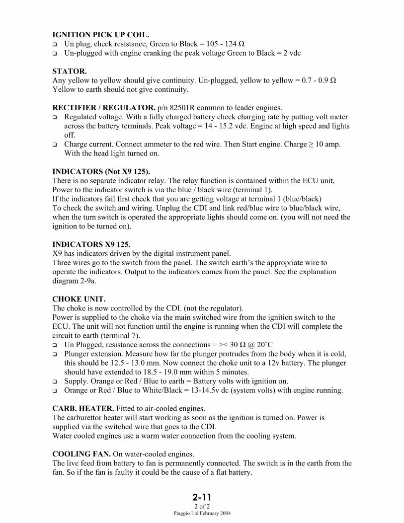
2-112 of 2
Piaggio Ltd February 2004
IGNITION PICK UP COIL. Un plug, check resistance, Green to Black = 105 - 124 Ω Un-plugged with engine cranking the peak voltage Green to Black = 2 vdc
STATOR.Any yellow to yellow should give continuity. Un-plugged, yellow to yellow = 0.7 - 0.9 ΩYellow to earth should not give continuity.
RECTIFIER / REGULATOR. p/n 82501R common to leader engines. Regulated voltage. With a fully charged battery check charging rate by putting volt meter
across the battery terminals. Peak voltage = 14 - 15.2 vdc. Engine at high speed and lightsoff.
Charge current. Connect ammeter to the red wire. Then Start engine. Charge ≥ 10 amp.With the head light turned on.
INDICATORS (Not X9 125).There is no separate indicator relay. The relay function is contained within the ECU unit,Power to the indicator switch is via the blue / black wire (terminal 1).If the indicators fail first check that you are getting voltage at terminal 1 (blue/black)To check the switch and wiring. Unplug the CDI and link red/blue wire to blue/black wire,when the turn switch is operated the appropriate lights should come on. (you will not need theignition to be turned on).
INDICATORS X9 125.X9 has indicators driven by the digital instrument panel.Three wires go to the switch from the panel. The switch earth’s the appropriate wire tooperate the indicators. Output to the indicators comes from the panel. See the explanationdiagram 2-9a.
CHOKE UNIT.The choke is now controlled by the CDI. (not the regulator).Power is supplied to the choke via the main switched wire from the ignition switch to theECU. The unit will not function until the engine is running when the CDI will complete thecircuit to earth (terminal 7).
Un Plugged, resistance across the connections = >< 30 Ω @ 20˚C Plunger extension. Measure how far the plunger protrudes from the body when it is cold,
this should be 12.5 - 13.0 mm. Now connect the choke unit to a 12v battery. The plungershould have extended to 18.5 - 19.0 mm within 5 minutes.
Supply. Orange or Red / Blue to earth = Battery volts with ignition on. Orange or Red / Blue to White/Black = 13-14.5v dc (system volts) with engine running.
CARB. HEATER. Fitted to air-cooled engines.The carburettor heater will start working as soon as the ignition is turned on. Power issupplied via the switched wire that goes to the CDI.Water cooled engines use a warm water connection from the cooling system.
COOLING FAN. On water-cooled engines.The live feed from battery to fan is permanently connected. The switch is in the earth from thefan. So if the fan is faulty it could be the cause of a flat battery.

Piaggio, Gilera & Vespa
Immobilisersystems
The following pages are an explanation of the original fitmentimmobiliser systems fitted to vehicles beginning in the
1990's with the original (pre Leader) Vespa ET4.
Most space is devoted to the system fitted to Leader enginedvehicles because this is by far the most common.
Much of the operation of other systems is the same as the Leadersystem.
Systems covered:
LeaderPre Leader
QuasarMaster
Published January 20061st edition
Piaggio and other after market alarms and immobilisersare not covered here.
Copies of this and other Piaggio technical information can be obtainedfrom the Piaggio UK dealer portal web site
or from Piaggio Ltd.

Immobiliser SystemsINDEX
LEADER
Page 2 - Explanation of operation & Fault codes
Page 3 - I need new keys
Page 4 - I need new locks
Page 5 - I need to fit a new CDI / Immobiliser unit
Page 6 - No Spark - Fault Finding Flow Chart
Page 7 - LED Not Flashing - Power supply problem
Page 8 - Immobiliser functioning correctly
Page 9 - Programming a CDI / Immobiliser
Page 10 - Transponder not detected
Page 11 - Transponder not recognised
PRE LEADER
Page 12 - Explanation of operation & Fault codes
Page 13 - Pre Leader ET4 wiring explanation
QUASAR
Page 14 - Explanation of operation & Fault codes
Page 15 - Notes on fault codes and diagnostic tester
Page 16 - Programming
MASTER
Page 17 - Explanation of operation & Fault codes
Page 18 - Notes on fault codes
Page 19 - Programming

Possible LED Flashing Fault Codes
TUR
N IG
NIT
ION
ON
LED OFF
LED ON
2 x 0.5 sec.
2 x 0.5 sec.0.7 sec.
2 sec.
LED OFF
LED ON
Phase 1 Phase 2 Phase 3
1. Immobiliser not programmed2. Transponder is detected3. Engine will run to 2000rpm
1. Immobiliser is programmed2. Transponder is not detected3. Ignition is not possible
LED OFF
LED ON1. Immobiliser not programmed2. Transponder is not detected3. Engine will run to 2000rpm
2 sec.
3 x 0.5 sec.0.7 sec.
LED OFF
LED ON1. Immobiliser is programmed2. Transponder is not recognised3. Ignition is not possible
0.7 sec.
LED OFF
LED ON1. Immobiliser is programmed2. Transponder is detected3. Engine can run normally
page 2
19/01/2006PAGE 2 EXPLANATION
Leader Immobiliser
1. The immobiliser system fitted to all Piaggio, Gilera & Vespa "Leader" engined vehicles operates in exactly the same way.2. Although the principle is the same the wiring differs on different models.
Refer to the wiring diagram and Service Station Manual for your specific model.3. CDI and immobiliser are combined in one unit.4. The CDI / immobiliser units may look the same but:
They have different characteristics on different models.Ensure you fit the correct unit. Always order by part number .
5. The flashing LED on the instrument panel is the key to understanding how the immobiliser is behaving. The list below shows what the LED can tell you. Note that the LED should flash steadily all the time the ignition is off and the battery is connected. If not, go to PAGE 7 for fault finding information.6. If you have no spark you must first prove that it is not due to the immobiliser.7. Keys should not be on a metal key ring or with other keys. Sometimes this can upset the system.

19/01/2006PAGE 3 NEW KEYS
Leader Immobiliser
FAULT: I need new keys.
I have theMaster key
You must changeThe lock set and
The CDI / Immobiliser
I have theservice key
Take the key to anautomotive lock smith.
They will be able to clone it.
Obtain a blank service key,get it cut and program theimmobiliser to recognise it
See: PAGE 9
YES
NO
NO
It is not possible to program in anew key without the master key.Fortunately automotive locksmiths can create a clone that willnot need programming.
It is not possible to buy an extramaster key or have one made.
It is not possible to by pass theimmobiliser.The code card does not containany electronic data and is onlyused to cut the key by number.
See PAGE 4 & 5
Tell your customer to onlyuse the service key and keep
the master key in a safeplace at home
OR
YES
Gilera Runner service keysThe red service key for Runner two strokes and Runner four strokes now look the same.
The four stroke key has a transponder chip in it and the two stroke key does not.You can recognise the keys which contain a transponder by a symbol that is engraved on the key
This key contains atransponder
page 3

page 4
19/01/2006PAGE 4 NEW LOCKS
Leader Immobiliser
FAULT: I need to fit new locks.
Is the originalmaster keyavailable?
1. Fit the new lock set2. Remove the chip from the original master key and fit it to the new master key.3. The immobiliser will not know anything has changed4. Program the the new service key to the immobiliser. See PAGE 9
You must fit a new lock set and a newCDI / Immobiliser unit
It is not possible to bypass theimmobiliser.
See PAGES 4 & 5
The lock set is supplied with one(brown) master key and one service key.
YESNO

19/01/2006PAGE 5 NEW CDI
Leader Immobiliser
FAULT: I need to fit a new CDI / Immobiliser.
I have themaster & service
keyYES
I only havethe master key
I only havethe service key
NO The replacement CDI / immobilisermust be new and unused.
Fit the new CDI and use the servicekey to check the engine starts andruns (only 2000 rpm)
Program the immobiliser.See: PAGE 9
Fit the new CDI and use the masterkey with the chip "out" to check theengine starts and runs(only 2000rpm)
You must replace the lock set
NO YES
Obtain a new service key
Tell your customer to only use theservice key and keep the masterkey in a safe place at home
3 2 18 7 6 5 4
antenna
Output to indicators
Ignition pick up
HT Coil
Earth
Choke unit
LED
Switched Live
Permanent Live
Battery+12v
FUSES
CDI / Immobiliser ConnectionsPlease refer to individual wiring diagrams andService Station Manuals for a full explanationand wiring colours.
1. Choke has a switched live, CDI earths it to complete the circuit and turn it off.
2. LED has a permanent live, CDI earths it to complete the circuit and make it come on.
3. X9 does not use the indicator function. Indicators are driven by the digital panel.
page 5
GREEN
BLACK
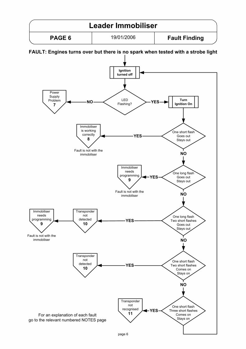
19/01/2006PAGE 6 Fault Finding
Leader Immobiliser
Ignitionturned off
PowerSupply
Problem7
One short flashGoes outStays out
TurnIgnition On
One long flashGoes outStays out
LEDFlashing?
Immobiliseris workingcorrectly
8
Immobiliserneeds
programming9
NO YES
One long flashTwo short flashes
Goes outStays out
One short flashTwo short flashes
Comes onStays on
One short flashThree short flashes
Comes onStays on
Fault is not with theimmobiliser
Immobiliserneeds
programming9
Transpondernot
detected10
Transpondernot
recognised11
Fault is not with theimmobiliser
Fault is not with theimmobiliser
Transpondernot
detected10
FAULT: Engines turns over but there is no spark when tested with a strobe light
For an explanation of each faultgo to the relevant numbered NOTES page
YES
YES
YES
YES
YES
NO
NO
NO
NO
page 6

19/01/2006PAGE 7 NO LED
Leader Immobiliser
3 2 18 7 6 5 4
CDI / Immobiliser
PERMANENT LIVE
SWITCHED LIVE
LED
EARTH
FAULT: With Ignition turned off the LED light is not flashing
Refer to
indiv
idual
models
wiring d
iagram
to id
entify
wire
colou
rs
ChargedBattery
?
Ensure afully charged
battery is connected
LEDFunctioning
?
Un-plug the CDIConnect LED wire to earth
LED should light up
PermanentLive toCDI ?
1. Check Fuse.2. Check continuity of wire to instruments.3. Check continuity of wire from instruments to CDI.
YES
NO
DON'TKNOW
NO
YES
SwitchedLive toCDI ?
GoodEarth
?
YES
YES
1. Check Fuse.2. Check continuity of wire from fuse to CDI.
1. Check Fuse.2. Check continuity of wire from fuse to ignition switch.3. Check continuity of wire from ignition switch to CDI.
Check continuity from CDIconnector to battery negative
NO
NO
NO
Returnto
Page 6
page 7
Note. With an all new / virgin system the LED may not be flashing but thecheck function flashes should occur when the ignition is turned on.

19/01/2006PAGE 8 Immobiliser OK
Leader Immobiliser
Ignitionturned off
One short flashGoes outStays out
TurnIgnition On
LEDFlashing?
Immobiliseris workingcorrectly
8
YES
Fault is not with theimmobiliser
FAULT: Engines turns over but there is no spark when tested with a strobe light
YES
We know that the immobiliser is working correctly so the immobiliser system can now be ignoredand normal fault finding can be continued.
1. Test the ignition pick up.Un-plug the CDI. Green wire to earth = 105 - 124 ohms.
2. Test the HT coil (unplugged).Primary: Purple to Earth = 0.4 - 0.5 ohm.Secondary: HT to Earth = 3000 ohms (3k ohm).A 5000 ohms (5K ohm) resistor plug cap should be fitted.
3. Test earth continuity.Un-plug the CDI. Check continuity between black wire and battery negative.
If no fault has been found you should suspect the CDI unit.* Fit a new CDI (not from another bike)* Use the service key (not the brown master key)* Check that the spark is restored. engine should start but it will not rev beyond 2000 rpm.If the fault is cured you must program the CDI unit.GO TO PAGE 9 for programming information.
page 8

19/01/2006PAGE 9 PROGRAMMING
Leader Immobiliser
FAULT: I need to program the immobiliser unitNotes.1. It is not possible to re-program an immobiliser unit to a new master key.
Once it has been programmed it is irrevocably linked to that master key.2. It is not normally possible for an immobiliser to loose it's program and then need
re-programming.If it was programmed and working but now it is saying that it is not programmed,First, check the HT lead and plug cap, It is possible that extreme electricalinterference from a faulty HT circuit could upset the immobiliser.Plug cap must be at least 5000 ohms. Change the cap and lead if suspect.A resistor plug must be used on all Leader engines.Then try re-programming the immobiliser.If it will not re-program then it is faulty.
Programming a new immobiliser.1. Do not attempt to program a new immobiliser until you know that the fault is cured.
Attach the new immobiliser, use the service key (not the brown master key)LED will give one long flash then go out and stay out. System is working correctly,Immobiliser is not programmedThe engine should start but will not rev above 2000 rpm until the immobiliser isprogrammed.
2. To program a new immobiliser* Insert the brown master key and turn on for two seconds* Insert the service key and turn on for two seconds* (extra service keys are included here)
- Insert the extra service key and turn on for two seconds* Insert the brown master key and turn on for two seconds
* The timing of the two seconds can be critical so use a watch to time it, you may need to do the sequence several times before it is accepted.* Changing from one key to the next should be done within ten seconds.* An extra service key is not just added, you must go through re-programming all the keys as above. You are not re-programming the master key, the master key is giving permission for the service keys to be added.* You do not need to start the engine just to check if the programming has been successful, Just turn on the ignition and watch the LED. One short flash (half second) means the programming was successful. One long flash (two seconds) means the system is still not programmed.
page 9
Possible LED Flashing Codes
TUR
N IG
NIT
ION
ON
LED OFF
LED ON
Phase 1 Phase 2 Phase 3
1. Immobiliser not programmed2. Transponder is detected3. Engine will run to 2000rpm
2 sec.
0.7 sec.
LED OFF
LED ON1. Immobiliser is programmed2. Transponder is detected3. Engine can run normally

19/01/2006PAGE 10 NOT DETECTED
Leader Immobiliser
FAULT: Transponder not detected.
Possible LED Flashing Codes
TUR
N IG
NIT
ION
ON LED OFF
LED ON2 x 0.5 sec.
2 x 0.5 sec.0.7 sec.
2 sec.
LED OFF
LED ON
Phase 1 Phase 2 Phase 3
1. Immobiliser not programmed2. Transponder is not detected3. Ignition is possible
1. Immobiliser is programmed2. Transponder is not detected3. Ignition is not possible
The immobiliser knows the ignition has been turned on but it has not been able to detect thetransponder chip in the key.
Possible reason for transponder chip not being detected.
1. The transponder chip is damaged or missing from the key.* Try another key.
2. The aerial is damaged, un-plugged or not correctly positioned* Un-plug the aerial from the CDI and check the aerial for continuity. Aerial resistance = 7 to 9 ohms. If resistance is wrong replace the aerial.* Check that the black plastic aerial housing is securely clipped into position around the ignition switch.* Inspect the pins in the plug and socket for signs of damage or corrosion.
page 10

19/01/2006PAGE 11 NOT RECOGNISED
Leader Immobiliser
Possible LED Flashing Codes
TUR
N IG
NIT
ION
ON
LED OFF
LED ON3 x 0.5 sec.
Phase 1 Phase 2 Phase 3
1. Immobiliser programmed2. Transponder is not detected3. Ignition is not possible
0.7 sec.
FAULT: Transponder is not recognised.
The immobiliser has seen the transponder chip so you know that the chip in the key is intactand the aerial is working correctly.
Possible reasons for the transponder not being recognised.
1. The wrong key is being used.It is possible for two keys to have the same cut profile on different vehicles(there are limited number of profiles).If the keys were mixed up you could turn on the ignition but the immobiliser would notrecognise the chip.
2. The key you are using has not been programmed into the immobiliser.See PAGE 9 for details of programming .
page 11

19/01/2006PAGE 12 EXPLANATION
Non Leader Immobiliser
The original Vespa ET4 (ZAPM04) was powered by an air-cooled four stroke engine that lookedsimilar but was very different to the Leader engine.On the next page there is an explanation of the wiring for this engine.
Immobiliser operation once the system is programmed and working correctly:CDI is irrevocably linked to the immobiliserImmobiliser is irrevocably linked to the red master key.It is possible to fit a new CDI alone.It is not possible to fit a new immobiliser alone, you must also change the CDI.It is not possible to change the red key alone.
Fault finding:* Fault finding is done either with the diagnostic tester or a 12 volt LED.* The tester is explained in the service station manual. Using an LED is explained here.* The vehicle is not fitted with an LED in the instrument panel.* You must connect a 12 volt LED to the test socket.* The test socket is a grey two pin plug with nothing plugged into it located in a large rubber sheath on the right side of the engine bay.* Remove the helmet storage to access the socket.
Note. Keys should not be on a metal key ring or with other keys. Sometimes this can upset the system.
page 12
Possible LED Flashing Fault Codes
TUR
N IG
NIT
ION
ON
LED OFF
LED ON
0.5 sec.0.7 sec.
Phase 1 Phase 2 Phase 3
1. CDI not programmed2. Transponder is detected3. Engine will run to 2000rpm
LED OFF
LED ON 1. Immobiliser is programmed2. Break in serial line (orange) or decoder earth (black)3. Ignition is not possible
2 sec.
2 x 0.5 sec.0.7 sec.
LED OFF
LED ON 1. Immobiliser is programmed2. Transponder is not detected3. Ignition is not possible
3 x 0.5 sec.0.7 sec.
LED OFF
LED ON 1. Immobiliser is programmed2. Transponder is not recognised3. Ignition is not possible
0.7 sec.
LED ON
LED OFF
1. Immobiliser is programmed2. Transponder is detected3. Engine can run normally
4 x 0.5 sec.0.7 sec.1. Immobiliser is programmed2. Virgin immobiliser, programmed CDI3. Ignition is not possible
LED ON
LED OFF
Immobiliseris workingcorrectly

19/01/2006PAGE 13 ZAPM 04 Later version
Vespa ET4 125 charge / ignition (non Leader)
VOLTAGESTABILISER
DECODER
3 5 8 6 4
CDI UNIT
3 2 1V G W B R
ORANGE
ANTENNA
(Serial Line)
DCSERVICES
ACSERVICES
GREEN
GREEN
WHITE
BROWN
RED
YELLOW
LIGHT BLUE
LIGHT BLUE
WHITE / RED
PINK
LIGHT BLUE
BLACK / BLUE
PIN
K
Lt. BLUE
BLUE
BLUE
WHITE
WHITE
PURPLE
GR
EY /
BLU
E
GREY
GR
EY
WH
ITE
YELL
OW
NOTES.* This Diagram shows the non "Leader" ET4 125 with the later type 8 pin rectifier / regulator.* This charging and ignition system is very similar to Piaggio 50cc 2 strokes and totally different to the later "Leader" engined ET4 125.* Three separate systems. DC, AC and ignition.* Ignition is self generating. The green wire (charging coil) is shorted to earth to stop the engine.
Immobiliser. See separate notes for a full explanation of the immobiliser system.* PINK wire is non switched live (battery voltage) feed to the immobiliser.* WHITE / RED is voltage stabilised power for immobiliser and CDI.* When ignition switch is turned on the immobiliser and CDI are energised via the LIGHT BLUE wire. The immobiliser uses the antenna to look for a recognised unique code from the key being used. If the immobiliser recognises the key they it sends another unique code to the CDI via the ORANGE wire (serial line). If the CDI does not receive that code it will not operate. It is this code that makes it impossible to bypass the immobiliser box.* The diagnostic test socket will be found when the helmet compartment is removed. Look on the right side for a large rubber shroud protecting several plugs and sockets. The diagnostic socket is a grey two pin socket with nothing plugged into it. You can connect a 12v LED or the diagnostic tester to this socket. Test box use is well covered in the Service Station Manual. Testing using 12v LED is covered in these notes.
Tests. See the service station manual for a full explanation of testing the system.Ignition. Stator (un-plugged) Green-White = 300 - 400 ohms. Red-Brown = 90 -140 ohms. Loom. Unplug stator and CDI. Green wire should give continuity to earth with ignition OFF and no continuity with ignition ON.Charging. AC section. Un-plug regulator. Grey - Earth = 25v AC with engine at about 3000 rpm. DC section. Ammeter between Battery + and red wire = at least 1.8 amps, fully charged battery Disconnect battery. yellow - red = at least 15v AC @ 3000 rpm.
IMMOBILISER UNIT
RED / BLUE
21 3 4 5 6 7 8
RECTIFIER / REGULATOR
1. AC out2. AC in3. not used4. not used5. DC out6. Earth7. Indicators8. DC in
HT COIL
BATTERY12v
+
7.5 AMPFUSE
PINK
RED
DiagnosticTest Socket
OFFON
IGNITION SWITCH
To In
dica
tors
WHITE / RED
GREEN
BLU
E
WH
ITE
RED
GR
EEN
BLA
CK
page 13

19/01/2006PAGE 14 EXPLANATION
Quasar Immobiliser
page 14
The 250 cc Quasar engine is available with a CV carburettor or semi closed loop fuel injection.The Quasar engine with a carburettor has exactly the same immobiliser function as a Leaderengine.The Injected engine is detailed below.This is only a quick reference guide for basic fault finding of the immobiliser system.For a full explanation please see the Service Station manual.
The Quasar has an ECU with a separate immobiliser which is built into the aerial, so the ECU mustobtain authority from the aerial (active antenna).
Keys should not be on a metal key ring or with other keys. Sometimes this can upset the system.
Possible LED Flashing Codes
TUR
N IG
NIT
ION
ON
LED OFF
LED ON
0.5 sec.0.7 sec.
Phase 1 Phase 2 Phase 3
1. ECU not programmed2. Transponder is detected3. Engine will run to 2000rpm
LED OFF
LED ON 1. Immobiliser is programmed2. Break in serial line (ECU to aerial)3. Ignition is not possible
2 sec.
2 x 0.5 sec.0.7 sec.
LED OFF
LED ON 1. Immobiliser is programmed2. Transponder is not detected3. Ignition is not possible
3 x 0.5 sec.0.7 sec.
LED OFF
LED ON 1. Immobiliser is programmed2. Transponder is not recognised3. Ignition is not possible
0.7 sec.1. Immobiliser is programmed2. Transponder is detected3. Engine can run normally
LED ON
LED OFF
LED OFF
LED ON 1. ECU not programmed2. Transponder is not detected3. Ignition is not possible
AnyKey
AnyKey
ServiceKey
MasterKey
ServiceKey
ServiceKey
ServiceKey
2 x 0.5 sec.0.7 sec.
LED OFF
LED ON 1. Immobiliser is programmed2. Two service keys are programmed3. Engine can run normally
Immobiliseris workingcorrectly
Could beany numberfrom 0 to 7
A
B
C
D
E
See Noteon the
Next Page

19/01/2006PAGE 15 NOTES
Quasar Immobiliser
LED flashing code notes.
A. ECU is not programmed.The LED gives a single two second flash. The Engine management light will be on.You should get this code when you have fitted a new ECU.The immobiliser system is working correctly and only needs programming.
B. ECU is not programmed. Transponder is not detected.The LED gives a single two second flash, then two short flashes, then comes back on..The ECU is not programmed (as above) but also the chip in the key has not been detected.You must resolve the transponder problem before trying to program the ECU.The master key will give this fault if the chip is hinged out.If you have another key try that, if it is still not detected it is probably the aerial.Verify that the aerial is correctly located and secure in it's mounting around the ignition lock.
C. Break in the Serial line.A single short flash, pause, then a second short flash, LED then comes back on.There is a break in the wire between the ECU and the aerial (active antenna).The Orange / White wire on pin 7. is the link.
D. Transponder is not detected.A single short flash, then two short flashes, then comes back on.The chip in the key has not been seen.Either there is a fault with the key or the aerial.If you have another key try that, if it is still not detected it is probably the aerial.Verify that the aerial is correctly located and secure in it's mounting around the ignition lock.
E. Transponder is not recognised.A single short flash, then three short flashes, then comes back on.The chip in the key is seen be is not recognised.The key is not programmed into the immobiliser memory.You are using the wrong key or it needs to be programmed into the immobiliser memory.
Diagnostic TesterIf you use the hand held diagnostic tester you can check the immobiliser.Select the "Errors" menu to see detailed fault information.
DISPLAY NOTES
Uncoded ECU Yes / No Yes = Virgin ECULED - one 2 sec flash in phase one (page 14 A)
Imm start inhib Yes / No Yes = Ignition is not possible (no spark).LED remaining on in phase three (page 14 B,C,D,E)
Universal code Yes / No For production assembly line use only. Yes = Virgin ECU
Key failure Yes / No Yes = Key transponder is not seen.LED - two flashes in phase two (page 14 D)
Wrong Key code Yes / No Yes = Key transponder is seen but not recognisedLED - three flashes in phase two (page 14 E)
Commun timeout Yes / No Yes = No signal from active antenna to ECULED - one flash in phase two (page 14 C)
Stored key num <value> Number of keys coded to the ECU (0 up to 7)
page 15

Programming.
Notes.
1. It is not possible to re-program an immobiliser unit to a new master key.Once it has been programmed it is irrevocably linked to that master key.
2. It is not normally possible for an immobiliser to loose it's program and then needre-programming.If it was programmed and working but now it is saying that it is not programmed,First, check the HT lead and plug cap, It is possible that extreme electricalinterference from a faulty HT circuit could upset the immobiliser.Plug cap must be at least 5000 ohms. Change the cap and lead if suspect.A resistor spark plug must be used.Then try re-programming the immobiliser.If it will not re-program then it is faulty.
Programming a new immobiliser.
1. Do not attempt to program a new immobiliser until you know that the fault is cured.Connect the new immobiliser, use the service key (not the brown master key)LED will give one long flash then go out and stay out. System is working correctly,Immobiliser is not programmedThe engine should start but will not rev above 2000 rpm until the immobiliser isprogrammed.
2. To program a new immobiliser* Insert the brown master key and turn on for two seconds* Insert the service key and turn on for two seconds* (any extra service keys are included here)
- Insert the extra service key and turn on for two seconds* Insert the brown master key and turn on for two seconds
* The timing of the two seconds can be critical so use a watch to time it, you may need to do the sequence several times before it is accepted.* Changing from one key to the next should be done within ten seconds.* An extra service key is not just added, you must go through re-programming all the keys as above. You are not re-programming the master key, the master key is giving permission for the service keys to be added.* It is not the keys that are programmed. The immobiliser is being programmed to recognise the keys.* You do not need to start the engine just to check if the programming has been successful, Just turn on the ignition and watch the LED. One short flash (half second) means the programming was successful. One long flash (two seconds) means the system is still not programmed.
19/01/2006PAGE 16 PROGRAMMING
Quasar Immobiliser
page 16

19/01/2006PAGE 17 EXPLANATION
Master Immobiliser
page 17
The 500 cc Master engine has separate immobiliser and ECU.Once the system is programmed the ECU and immobiliser are irrevocably linked to the brownmaster key.
Keys should not be on a metal key ring or with other keys. Sometimes this can upset the system.
For a full explanation of fault finding please see the Service Station manual.
Possible LED Flashing Codes
TUR
N IG
NIT
ION
ON
0.5 sec.0.7 sec.
Phase 1 Phase 2 Phase 3
LED OFF
LED ON 1. Immobiliser is programmed2. Break in serial line3. Ignition is not possible
2 x 0.5 sec.0.7 sec.
LED OFF
LED ON 1. Immobiliser is programmed2. Transponder is not detected3. Ignition is not possible
3 x 0.5 sec.0.7 sec.
LED OFF
LED ON 1. Immobiliser is programmed2. Transponder is not recognised3. Ignition is not possible
0.7 sec.1. Immobiliser is programmed2. Transponder is detected3. Engine can run normally
LED ON
LED OFF
LED OFF
LED ON 1. Immobiliser not programmed2. ECU is programmed3. Ignition is not possible
2 sec.
AnyKey
ServiceKey
MasterKey
ServiceKey
ServiceKey
ServiceKey
2 x 0.5 sec.0.7 sec.
LED OFF
LED ON 1. Immobiliser is programmed2. Two service keys are programmed3. Engine can run normally
Immobiliseris workingcorrectly
Could beany numberfrom 0 to 7
A
B
C
D
See Noteon the
Next Page
E
2 sec.1. System not programmed2. Transponder is detected3. Engine runs only to 2000 rpm.
LED ON
LED OFF
AnyKey
19/01/2006PAGE 18 NOTES
Master Immobiliser
LED flashing code notes.
A. System is not programmed.The LED gives a single two second flash. The Engine management light will be on.You should get this code when you have fitted a new immobiliser and ECU.The immobiliser system is working correctly and only needs programming.
B. Immobiliser is not programmed, ECU is programmed.The LED gives one long flash, then four short flashes, LED then comes back on.Programming the immobiliser is only possible if the original master key is used.If the original master key (chip) is not available then you must change the ECU as well.
C. Break in the Serial line.A single short flash, pause, then a second short flash, LED then comes back on.Either there is a break in the orange / white wire between the immobiliser and ECU(serial line) or if the vehicle has a "fall over cut out" fitted it could be that.If the cut out is active it shorts the serial line to earth.The fall over sensor is located behind the fuel tank (Nexus) in a rubber mounting.
The fall over sensor must be mounted
THIS WAY UP
D. Transponder is not detected.A single short flash, then two short flashes, then comes back on.The chip in the key has not been seen.Either there is a fault with the key or the aerial.If you have another key try that, if it is still not detected it is probably the aerial or it's wires.Un-plug the aerial from the immobiliser and check for continuity.Check that the aerial is correctly located and secure in it's mounting.
E. Transponder is not recognised.A single short flash, then three short flashes, then comes back on.The chip is seen be is not recognised. The key is not programmed into the immobiliser.You are using the wrong key or it needs to be programmed into the immobiliser memory.
page 18
Programming.
Notes.
1. It is not possible to re-program an immobiliser unit to a new master key.Once it has been programmed it is irrevocably linked to that master key.
2. It is not normally possible for an immobiliser to loose it's program and then needre-programming.If it was programmed and working but now it is saying that it is not programmed,First, check the HT lead and plug cap, It is possible that extreme electricalinterference from a faulty HT circuit could upset the immobiliser.Plug cap must be at least 5000 ohms. Change the cap and lead if suspect.Also a resistor spark plug must be used.Then try re-programming the immobiliser.If it will not re-program then it is faulty.
Programming a new immobiliser.
1. Do not attempt to program a new immobiliser until you know that the fault is cured.Connect the new immobiliser, use the service key (not the brown master key)LED will give one long flash then go out and stay out. System is working correctly,Immobiliser is not programmedThe engine should start but will not rev above 2000 rpm until the immobiliser isprogrammed.
2. To program a new immobiliser* Insert the brown master key and turn on for two seconds* Insert the service key and turn on for two seconds* (any extra service keys are included here)
- Insert the extra service key and turn on for two seconds* Insert the brown master key and turn on for two seconds
* The timing of the two seconds can be critical so use a watch to time it, you may need to do the sequence several times before it is accepted.* Changing from one key to the next should be done within ten seconds.* An extra service key is not just added, you must go through re-programming all the keys as above. You are not re-programming the master key, the master key is giving permission for the service keys to be added.* It is not the keys that are programmed. The immobiliser is being programmed to recognise the keys.* You do not need to start the engine just to check if the programming has been successful, Just turn on the ignition and watch the LED. One short flash (half second) means the programming was successful. One long flash (two seconds) means the system is still not programmed.
19/01/2006PAGE 19 PROGRAMMING
Master Immobiliser
page 19
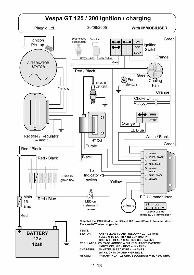
30/09/2005Piaggio Ltd. With IMMOBILISER
Vespa GT 125 / 200 ignition / charging
2 -13
Rectifier / Regulatorp/n: 82501R
GALTERNATORSTATOR
ToIndicatorswitch
Red
Green
Green
White / Black
Yellow
IgnitionPick up
ECU / Immobiliser
HT Coil
Main15amp
Orange
Orange
PurpleRed / Black
Red / Black
Black
Yellow
Red / BlueLED on
instrumentpannel
Layout of pinsin the ECU / immobiliser
BATTERY12v
12ah
+
RG4HCCR 9EB
CoolingFan
FanSwitch
Green
Choke Unit
Lt. Blue
Orange
GREEN
WHITE / BLACKLt. BLUE
RED / BLACK
PURPLEBLACK
BLUE / BLACK
YELLOW
3 2 18 7 6 5 4
Note that the ECU fitted to the 125 and 200 have different characteristics.They are NOT interchangeable.
TESTS.STATOR: ANY YELLOW TO ANY YELLOW = 0.7 - 0.9 ohm.
YELLOW TO EARTH = NO CONTINUITY GREEN TO BLACK (EARTH) = 105 - 124 ohm
REGULATOR: VOLTAGE ACROSS A FULLY CHARGED BATTERY, LIGHTS OFF, HIGH REVS = 14 - 15.2 V.
CHARGING: AMMETER IN RED WIRE = > 8 AMPS WITH LIGHTS ON AND HIGH REVS.
HT COIL: PRIMARY = 0.4 - 0.5 OHM. SECONDARY = 3K + 300 OHM.
STOP
RUN
6 1
8 3
4 5
7 2
antenna
Fuses inglove box
Red / Black
IgnitionSwitch
OFF
ON
LOCK
Seat releasepush button
Seat lock
Grey
Grey / BlueGrey / Black

WHITE / RED
YELLOW / BLACK
YELLOW / REDWHITE
RED / BLUE
GREY
RED / BLACK12v DC from battery
ORANGESwitched 12v
ORANGESwitched 12v
BLUE
BLUE
RED / BLACK12v DC from battery
19/08/2003Piaggio Ltd.
Vespa GT Fuses
3
7.5a
1
10a
2
7.5a
4
7.5a
5
5a
6
5a
The wire colours shown here are different to those "on line" and in the owners handbook.The colours and fuse functions here are correct, they were checked on GT200ZAPM312 * 2550.
FUSE:1. 10 amp. Electric seat release. Headlights. Main beam warning light.2. 7.5 amp. Intercom. Alarm. Immobiliser LED.3. 7.5 amp. Intercom. Alarm. Water temp. Fuel warning & guage. Oil pressure warning.4. 7.5 amp. Horn.5. 5 amp. Stop light. start switch.6. 5 amp. Side lights. Number plate light. Instrument panel lights.
MAIN FUSE.A 15 amp fuse is located at the front of the under seat compartment.
2-14

Rectifier /Regulatorp/n: 82501R
30/09/05Piaggio Ltd. With IMMOBILISER
Skipper ST ignition / charging
GALTERNATORSTATOR
ToIndicatorswitch
Headlightvia relay
Red
Green
Green
White /Black
Red / Blue
RG4HCCR 9E
Carb. Heater
Choke Unit
Yellow
IgnitionPick up
ECU / Immobiliser
IgnitionSwitch
HT Coil
Blue /Black
15amp
Ora
nge
Orange
Red
/Blu
e
Purple
Grey
Red / Blue
Powerto
services
Red / Blue
Black
antenna
Yellow
LED oninstrument
pannel
6 1
8 3
4 5
7 2 GREEN
WHITE / BLACKORANGE
RED / BLUE
PURPLEBLACK
BLUE / BLACK
YELLOW
Layout of pinsin the ECU / immobiliser
BATTERY12v9ah
+
3 2 18 7 6 5 4
TESTS.STATOR: ANY YELLOW TO ANY YELLOW = 0.7 - 0.9 ohm.
YELLOW TO EARTH = NO CONTINUITY GREEN TO BLACK (EARTH) = 105 - 124 ohm
REGULATOR: VOLTAGE ACROSS A FULLY CHARGED BATTERY, LIGHTS OFF, HIGH REVS = 14 - 15.2 V.
CHARGING: AMMETER IN RED WIRE = > 8 AMPS WITH LIGHTS ON AND HIGH REVS.
HT COIL: PRIMARY = 0.4 - 0.5 OHM. SECONDARY = 3K + 300 OHM.
OFF
ON
2-15

RED / BLUE
ORANGE
RED / BLUE
RED / BLUERED
06/01/2004Piaggio Ltd. Leader Engine
SKIPPER ST 125 FUSE EXPLANATION
RED12 V DC from battery
3
5a
1
7.5a
2
5a
4
5a
RED / WHITEClock & Interphone Socket
RED / BLACKTo Light Switch
GREY / REDTo Main / Dip Switch
WHITEGeneral
2 15 amp
1 15 ampGREYTo Head Light Relay
OFF
ON
IGNITION SWITCH
2-16

The early Skipper ST did not have an immobiliser. The speedo unit for this vehicle581308 (or 581307) is no longer available.It must be replaced with 583271, this is the speedo fitted to later Skipper ST withimmobiliser.To fit this new speedo you must make some modifications to the wiring at the plugswhich connect to the speedo unit.Below are diagrams that show the plugs on the wiring loom as they appear on the vehicleand also how they must appear to enable the new speedo to be used.1. Confirm that the wiring on your vehicle is as shown on the "Original Loom" diagram2. Remove the white / green and yellow / green wires from the large plug complete withtheir connectors.3. Remove the white and the brown wires from the small plug complete with theirconnectors.4. Re-fit these wires in the positions shown on the "Modified Loom" diagram.It is possible to remove the connectors by carefully inserting a small screwdriver orsimilar and pressing the retaining tag in.
View of the two plugs that connect to the speedometer
2-17
13/12/2005Piaggio Ltd. With IMMOBILISER
Replacing Skipper ST speedometer
ORIGINALLOOM
WHITE / BLUE
VIOLET
BLACKYELLOW / BLACK
WHITE / GREEN
YELLOW / GREEN
BLACK
MODIFIEDLOOM
WHITE / BLUE
VIOLET
BLACKYELLOW / BLACK
WHITE / GREEN
YELLOW / GREEN
BLACK
RED
WHITE
BROWN
RED
WHITE
BROWN

Rectifier /Regulator
05/05/2004Piaggio Ltd. QUASAR Engine
X9 250 Evo ignition / charging
GALTERNATORSTATOR
Red
Green
Green
White / Black
Yellow
IgnitionPick up
ECU / Immobiliser
IgnitionSwitch
15amp
Orange
Orange
Red / Black
Yellow
Layout of pinsin the ECU / immobiliser
Yellow / Grey
BATTERY12v
12ah
+
CoolingFan
Fan Switch
Red / Black
Green
Choke Unit
EmergencyStop
Lt. Blue
Orange
7.5amp
Diagnosticsocket
2 GREEN
7 WHITE / BLACK
5 Lt. BLUE
4 RED / BLACK
3 PURPLE8 BLACK
6 YELLOW
Red / Black
Yellow / BlueYellow / Green
Gre
y / B
lack
Lt. Blue
TESTS.STATOR: ANY YELLOW TO ANY YELLOW = 0.7 - 0.9 ohm.
YELLOW TO EARTH = NO CONTINUITY GREEN TO BLACK (EARTH) = 105 - 124 ohm
REGULATOR: VOLTAGE ACROSS A FULLY CHARGED BATTERY, LIGHTS OFF (Remove front 10 A fuse) , HIGH REVS = 14 - 15.2 V.
CHARGING: AMMETER IN RED WIRE = > 8 AMPS WITH LIGHTS ON AND HIGH REVS.
HT COIL: PRIMARY = 0.4 - 0.5 OHM. SECONDARY = 3K + 300 OHM.
3 2 18 7 6 5 4
RG4HCCR 9EB
HT Coil
Purple
Black
SideStandSwitchRed / White
STOP
RUN
STOP
RUN
UP
DOWN
2-18
ImmobiliserLED
StandWarning
Power toServices
antenna NOTE.Indicators are powered bythe digital instrument panel.
7.5amp
Gre
en
Yel
low
/ G
reen
Yel
low
/ Bl
ack
Bla
ck
Main Relay
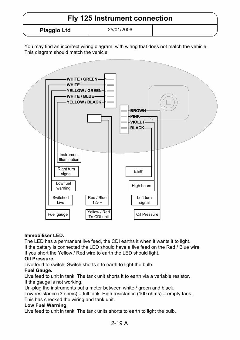
25/01/2006Piaggio Ltd
Fly 125 Instrument connection
You may find an incorrect wiring diagram, with wiring that does not match the vehicle.This diagram should match the vehicle.
Immobiliser LED.The LED has a permanent live feed, the CDI earths it when it wants it to light.If the battery is connected the LED should have a live feed on the Red / Blue wireIf you short the Yellow / Red wire to earth the LED should light.Oil Pressure.Live feed to switch. Switch shorts it to earth to light the bulb.Fuel Gauge.Live feed to unit in tank. The tank unit shorts it to earth via a variable resistor.If the gauge is not working.Un-plug the instruments put a meter between white / green and black.Low resistance (3 ohms) = full tank. High resistance (100 ohms) = empty tank.This has checked the wiring and tank unit.Low Fuel Warning.Live feed to unit in tank. The tank units shorts to earth to light the bulb.
Oil Pressure
Left turnsignal
High beam
Earth
Yellow / RedTo CDI unit
Red / Blue12v +
Right turnsignal
Low fuelwarning
SwitchedLive
InstrumentIllumination
Fuel gauge
BLACKVIOLET
WHITE / BLUE
BROWNPINK
WHITE / GREENWHITEYELLOW / GREEN
YELLOW / BLACK
5
4
3
2
1
2-19 A

Rectifier /Regulatorp/n: 82501R
21/10/04Piaggio Ltd. With IMMOBILISER
Fly 125 ignition / charging
GALTERNATORSTATOR
ToIndicatorswitch
Red
Green
Green
Whi
te /
Bla
ck
Red / Blue
RG4HCCR 9E
Yellow
IgnitionPick up
ECU / Immobiliser
IgnitionSwitch
HT Coil
Blue / Black
15amp
Ora
nge
Orange
White
Red
/ B
lue
Purple
Red / Blue
Powerto
services
Red / BlueB
lack
antenna
Yellow
LED oninstrument
pannel
Diagnosticsocket
6 1
8 3
4 5
7 2 GREEN
WHITE / BLACKORANGE
RED / BLUE
PURPLEBLACK
BLUE / BLACK
YELLOW
Layout of pinsin the ECU / immobiliser
Orange
7.5amp
BATTERY12v9ah
+
3 2 18 7 6 5 4
TESTS.STATOR: ANY YELLOW TO ANY YELLOW = 0.7 - 0.9 ohm.
YELLOW TO EARTH = NO CONTINUITY GREEN TO BLACK (EARTH) = 105 - 124 ohm
REGULATOR: VOLTAGE ACROSS A FULLY CHARGED BATTERY, LIGHTS OFF, HIGH REVS = 14 - 15.2 V.
CHARGING: AMMETER IN RED WIRE = > 8 AMPS WITH LIGHTS ON AND HIGH REVS.
HT COIL: PRIMARY = 0.4 - 0.5 OHM. SECONDARY = 3K + 300 OHM.
OFF
ON
2-19
Carb. Heater
Choke Unit
Yellow / Red
Toheadlight
switchO
rang
e

Rectifier /Regulator
04/01/2005Piaggio Ltd. With IMMOBILISER
X8 125 / 200 ignition / charging
GALTERNATORSTATOR
Red
Green
Green
White / Black
Yellow
IgnitionPick up
IgnitionSwitch
15
Orange
Red
Yellow
Layout of pinsin the ECU / immobiliser
Yel
low
/ B
lue
BATTERY12v
12ah
+
CoolingFan
Fan Switch
Red
Green
Choke Unit
EmergencyStop
Lt. Blue
Orange
Diagnosticsocket
Red
TESTS.STATOR: ANY YELLOW TO ANY YELLOW = 0.7 - 0.9 ohm.
YELLOW TO EARTH = NO CONTINUITY GREEN TO BLACK (EARTH) = 105 - 124 ohm
REGULATOR: VOLTAGE ACROSS A FULLY CHARGED BATTERY, LIGHTS OFF, HIGH REVS = 14 - 15.2 V.
CHARGING: AMMETER IN RED WIRE = > 8 AMPS WITH LIGHTS ON AND HIGH REVS.
HT COIL: PRIMARY = 0.4 - 0.5 OHM. SECONDARY = 3K + 300 OHM.
3 2 18 7 6 5 4
RG4HCCR 9EB
HT Coil
Purple
Black
Red
/ G
reen
STOP
RUN
STOP
RUN
2-20
ImmobiliserLED
Power toServices
antenna
Red
/ B
lack
Red / BlueRed / Black
10
5
Rear FuseBox
To IndicatorSwitch
ECU / Immobiliser
2 GREEN7 WHITE / BLACK
5 Lt. BLUE
4 RED
3 PURPLE
8 BLACK
6 YELLOW
1 BLACK / BLUE

30/09/2005Piaggio Ltd. Piaggio Ltd.
X8 125 Seat & Trunk Release
2-21
GREEN
LOCK
OFF
ON
RED / BLACK
BATTERY12v
+
RED / BLUE
ORANGE / WHITE
OR
AN
GE
123467
101112
RED / BLACK
SEAT RELEASEBUTTON
TRUNKSOLENOID
TRUNK RELEASEBUTTON
SEATSOLENOID
IGNITION SWITCH
SOLENOIDCONTROL UNIT
ANTENNA
10 A
WHITE
OR
AN
GE
/ W
HIT
E
YE
LLO
W
VIO
LET
/ BLU
E
OR
AN
GE
/ B
LAC
K
ORANGE / WHITE
YELLOW
BLACK
RE
D /
BLU
E
RE
D
RED
RED / BLACK
RED / BLUE
VIOLET
SOCKET FOR ALARM
RED / BLUE
10 A
15 A
FRONTFUSE BOX
GR
EE
N
REARFUSE BOX

04/02/2004Piaggio Ltd. Honda XLR 125w Engine
Coguar 125 Charging & Ignition
RECTIFIER / REGULATOR
BLUE YELLOW / BLUE
ORANGE
YELLOW
YELLOW
YELLOW
YELLOW
YELLOW
YELLOW
RED
GREEN BLACK
RED
RED
NOTESThree phase charging with inductive low voltage ignition.The start & run permissive circuit is shown here in lighter detail.For the engine to run the ECU must be earthed via the White / Green wire.TESTSStator: Any yellow to any yellow = 0.8 ohm. Any yellow to earth should give NO continuity.Regulated voltage: 14.0 - 14.8 volts with fully charged battery and lights on. Engine running at 5000 rpm.
DPR8 EA9FUSES
1 X 20 AMP1 X 15 AMP
STATOR
PICKUP
WHITE / BLUE
BLACK
BLUE
YELLOW / RED
WHITE / GREEN
IGNITIONUNIT(ECU)
STOP
RUN
OFF
ONIGNITIONSWITCH
RED / BLACK GREEN
WHITE / GREEN
YELLOW / RED
3 - 1
M
STARTERBUTTON
STARTERRELAY
NEUTRALLIGHT
STANDWARNING
LIGHT
BATTERY12v
+
NEUTRALSWITCH
NEUTRAL
IN GEAR
CLUTCHSWITCH
IN
OUT
STANDSWITCH
DOWN
UP
20 15

11/09/2003Up to ZAP04 * 51159 5 pin regulator
Vespa ET4 (ZAPM04) charging
7.5 ampFUSE
YELLOW
BLUE RED
DC SERVICES
RED
WHITE
* This diagram shows the early ET4 (non Leader) wiring using a five pin connector on the rectifier / regulator. Refer to the separate diagram for later circuit using an eight pin rectifier / regulator.* Three completely separate circuits for AC, DC & ignition.
AC is full wave and regulatedDC is half wave rectified and regulatedIgnition is the self powered CDI type typical on our two stroke scooters. Shorted to earth to stop.
* Engine must be earthed to the chassis / battery. Lack of this connection will affect the AC circuit and starter motor but not the DC circuit or ignition circuit.* If voltage at the B+ terminal falls below 8v (approx) the DC rectifier / regulator will not function so there will be no output from the alternator on the DC circuit.* Separate indicator relay.* The choke is powered by the DC circuit but the relay to activate it is controled by the AC circuit. Circuit will only be completed when both: AC is present at relay terminal "B" and +12v DC is NOT present at the unmarked terminal.TESTS.1. Grey / Blue to earth = 25-30v AC stator un-plugged and engine at 2000rpm.2. Yellow to Blue = 26-30v AC stator and battery disconnected and engine at 2000 rpm.3. Ammeter between red wire and battery positive = 1.5-2 amp with fully charged battery and engine at 2000 rpm
AC SERVICES
CHOKE UNIT
2
GR
EEN
GREY
WHITE / RED
CHOKE CONTROLRELAY
GREEN BOXUNDER THE SEAT
L EB (-)
+12v DC fromstart button
GR
EEN
/ BL
ACK
IGNITIONSWITCH
OFFON
BLUE
WH
ITE
GREEN
BLACK
BATTERY12v
+
BLAC
K
1
3
RED
WH
ITE
YELL
OW
GR
EY /
BLU
E
GR
EY
RECTIFIER&
REGULATOR
B+GAA
REGULATOR
3-2

11/09/2003From ZAPM04 * 51160 8 pin regulator
Vespa ET4 (ZAPM04) charging circuit
BATTERY12v
+
7.5 ampFUSE
RED / WHITE
DC SERVICESBrake light
Horn
RED
* This diagram shows the later (non Leader) ET4 wiring using an eight pin connector on the rectifier / regulator. Refer to the separate diagram for earlier circuit using a five pin rectifier / regulator.* The charging system is basically the same as the 50cc & 80cc two stroke Sferoids.* Two completely separate circuits for AC & DC.* Eight pin rectifier / regulator incorporates the indicator relay.* The choke is supplied with 12v DC when the ignition is turned on but the circuit to earth is only completed when the engine is running and 12v AC is supplied to the choke control relay.TESTS.1. Grey / Blue to earth = 25-30v AC stator un-plugged and engine at 2000rpm.2. Yellow to Blue = 26-30v AC stator and battery disconnected and engine at 2000 rpm.3. Ammeter between red wire and battery positive = 1.5-2 amp with fully charged battery and engine at 2000 rpm4. Output to the indicator switch will be a 12v DC pulse with ignition on.NOTES.* Engine must be earthed to the chassis / battery. Lack of this connection will affect the AC circuit and starter motor but not the DC circuit or ignition circuit.
3
YELLOW
BLUE
BLUE
WHITE
2
1
GREEN
GR
EEN
IGNITIONSWITCH
OFFON
WH
ITE
BLACK
CHOKE UNIT
TO INDICATORSWITCH
GREY / BLUE
WH
ITE
BLAC
K
WHITE / RED
4
GR
EY /
BLU
E
3 & 4NOT
USED
RECTIFIER&
REGULATORREGULATOR
GREY
BLUE / BLACK
YELLOW
1 2 3 4 5 6 7 8
ACSERVICESHead lightTail light
Instruments
GREY
WHITE
3-3

3-4Piaggio Ltd.page1 of 6
ET4 IGNITION IMMOBILISER.Original, Non Leader
General description
The ignition key contains an electronic digital code; this code must be recognised by the system beforethe ignition system will function.
Thus the scooter has two forms of security – the key must physically operate the lock (in the normal way),and the electronic code must be recognised by the system. In this way the scooter is safe against havingthe ignition switch forced, or being hot-wired.
Main components
Special keys, with built in transponders.The red key is the “master” key, which is used for programming, with the transponder mounted ina flip-out section.The blue key(s) is for normal use.
Decoder, which uses the antenna to read the electronic code of the key transponder.
CDI unit, which latches to the ON position only if an appropriate signal is received from the decoder.
Other components
Antenna, located encircling the ignition switch.
7.5 amp fuse, which supplies +12V DC to the voltage stabiliser (located within the decoder box).
Voltage stabiliser (located within the decoder box), whose output (+12V DC) supplies power to thedecoder and the CDI unit via contacts in the ignition switch.
“Serial Line”, connects the decoder to the CDI unit, and conveys the authorising signal enabling the CDIto latch to the “ON” position.
Diagnostic test socket under the helmet holding compartment.
Normal Operation
The key grip contains a passive electronic transponder – a device that contains a unique pre-set digitalcode, which can be read without direct electrical contact (similar to those used in the Datatag system).The keys do not need any power and they do not contain a battery.
When the ignition switch is turned on, the decoder interrogates the key’s transponder.
Only if the decoder recognises the transponder’s electronic digital code will it send a signal via the serialline to the CDI unit, enabling the otherwise conventional ignition system (alternator with pick-up andcharger coil, CDI unit and HT coil) to function.
However, the CDI unit and the decoder are also programmed to operate together as a matched pair; ifthey detect a mismatch the CDI unit will not allow ignition.

3-4Piaggio Ltd.page2 of 6
To check the correct operation of the system
IT IS IMPORTANT THAT ON PDI AND AFTER ANY WORK ON THE IMMOBILSER SYSTEM, THECORRECT OPERATION OF THE SYSTEM IS CHECKED.
• Insert the red key with the hinged transponder in the flipped out position (this takes it out of radiorange of the antenna, thus enabling the system to be tested without the antenna automatically pickingup a code).
• Turn the ignition on and try to start the engine. IT SHOULD NOT START.• Insert the blue key and try to start the engine. IT SHOULD START AND RUN NORMALLY.
Fault finding points to note
Decoder and CDI units are initially manufactured as blank units. In this state (“Virgin”) and up to the timethey are programmed the immobiliser system will not offer any protection, and the ignition will function ina conventional way. However, a “virgin” unit can be used as a substitute to aid in fault finding.
Programming functions can only be done with a red key. Once either the decoder or the CDI unit hasbeen programmed using a red key, they will only ever recognise that particular red key.
Therefore, it is vital that you USE ONLY THE BLUE KEY FOR ALL TESTING PURPOSES other than theprogramming procedure itself.
Diagnostic test procedure
If there is any fault with the system, the Immobiliser Test Box should be plugged in to the diagnostic testsocket. The test box (Part no 020319Y, Current dealer price £53.99 + VAT) is an invaluable, time savingtool, and one which without doubt should be owned by all dealers.
Proceed as follows-• With ignition off, turn on and wait for ‘On’ and ‘Pronto’ LEDs to illuminate.• Turn ignition on. The ‘Seriale’ LED will flash, showing the signal on the Serial line.• After a few seconds the appropriate LED will indicate the result of the diagnostic tests.
If the “No Serial line” LED lights up, it may be for the following reasons-Serial Line circuit is broken.Decoder is faultyCDI unit is faulty
However if no LEDs light up, it may be for the following reasons-+12V DC power supply failure.Decoder is faultyCDI unit is faulty
Before re-testing, press the reset button.

3-4Piaggio Ltd.page3 of 6
Diagnostic points to note-
To check for +12V DC power supply failure, check 7.5 amp fuse, and that +12V DC is present ondecoder terminals 3,5 and 8, and CDI unit terminal 1.
The CDI unit does not have its own earth lead, but is earthed to the alternator stator back-plate via thewhite wire from terminal W. However, note also that back-plate and the engine itself is only earthed viathe electric starter motor lead. The decoder has its own earth lead.
There are two different types of transponder/decoder system; each type is not compatible with the other.However this problem should only show up when trying to program new blue keys. In this case mostautomotive locksmiths will be able to “clone” a new blue key if they are provide with a functioning red key.These “cloned” keys will be recognised by the system without the need for programming.
Component replacement procedure
Component to be replaced ActionBlue key Follow programming procedure (pages 4-14,4-15 in SSM)-
1. Turn the ignition ON using the red key. After 1 to 3seconds turn OFF.
2. Within 10 seconds turn the ignition ON using a blue key.After 1 to 3 seconds turn OFF.
3. If needed, repeat step 2 up to seven times to programfurther spare keys.
4. Turn the ignition ON using the red key. After 1 to 3seconds turn OFF.
Red key Red key alone cannot be replaced.Follow appropriate replace lock set instructions
Lock set(if old red key available)
1. Replace lock set.2. Swap red transponder from old key into new key.3. Check for correct operation of system.4. Program new blue key using above procedure.
Lock set(if old red key not available)
1. Replace lock set, decoder and CDI unit.2. Check for correct operation of system.3. Program system as per blue key procedure above.
Decoder 1. Replace decoder (CDI must also be replaced).2. Check for correct operation of system. Note that with a
virgin decoder the engine will start, but won’t rev above2,000rpm.
3. Program system as per blue key procedure above
CDI unit 1. Replace CDI unit (CDI can be replaced on its own).2. Check for correct operation of system. Note that with a
virgin CDI unit the engine will start and run normally, butthe immobiliser system is inactive.
3. Program the CDI unit simply by turning on the ignitionswitch using the red key
When programming keys do not have more than one transponder type key on the key ring, as thedecoder may pick-up both transponders.

3-4Piaggio Ltd.page4 of 6
VESPA ET4 IMMOBILIZER DIAGNOSTICS
When fault finding the ignition system on VESPA ET4, there is a very simple and quick check, which canbe done to give the Immobiliser the ‘all clear’. If you don’t have the effort-saving Immobiliser Tester (partno. 020319Y) then insert a 12 Volt LED in the 2 pin socket (the blue/black lead is negative) located underthe helmet compartment and switch on the ignition whilst observing the LED. Note that the LED markedSeriale on the Tester display shows this same signal.
It is advisable to get into the habit of using the blue key for all use and testing purposes otherthan the programming procedure itself.
Normally-Functioning ImmobiliserThe signal for a normally functioning Immobiliser system is a quick flash (0.7 seconds) and then the LEDremains off.
Immobilizer Fault-Finding
If the system is not functioning normally, it is recommended to obtain the Piaggio Immobiliser Tester. Thisis by far the easiest way to diagnose faults. However, if for some reason this is not available, fault findingcan be done by observing the following.
Example Serial Line Signal0.7 secs 0.5 secs
LED on
2 secs 2 secs
LED off0.5 secs
Phase 1 Phase 2 Phase 3
The above diagram shows the trace of the diagnostic signal for Decoder and CDI Units bothprogrammed, using a key with an unknown transponder (Table 2, case 5), resulting in 3 FLASHES duringthe second phase of the diagnostic signal (Phase 2).
Phase 1: 0.7 sec flash = NORMAL OPERATION (Cases 7-14 in Table 2)2 sec flash = CDI Unit unprogrammed (Cases 1-6 in Table 2)BOTH of the above flashes will be followed by a 2-second pause.
Phase 2: A series of 0-4 flashes (0.5 sec each with 0.5 sec pauses) which form diagnostic signal (refer toTable 1).
Phase 3: LED remains OFF if no fault is detected or ON if a fault is detected in the Immobilizer system(the Tester does not consider a non-programmed CDI Unit a fault).
If the led does not light up at all try the following:
Possible Fault TestNo power supply to Immobiliser circuitry inCDI
12 V. should show on blue lead (pin 1 of theCDI unit).
Faulty Decoder unit Replace and test with BLUE KEYFaulty CDI unit Replace and test with BLUE KEY

3-4Piaggio Ltd.page5 of 6
Table 1: Immobilizer Diagnosis Chart
Phase 2LED Signal DIAGNOSIS0 FLASHES NORMAL OPERATION1 FLASH BREAK IN SERIAL LINE (ORANGE) OR DECODER EARTH (BLACK)2 FLASHES NO TRANSPONDER DETECTED - FAULTY KEY OR IMMOB. ANTENNA3 FLASHES TRANSPONDER DETECTED BUT NOT RECOGNISED BY IMMOB.4 FLASHES VIRGIN DECODER AND PROGRAMMED CDI UNIT
Table 2: Immobilizer Component Combinations and Related Diagnostic Signal
Phase 1Flash
Phase 2Signal Decoder
CDIUnit
KeyTransponder Antenna Spark Notes
1 2 sec 0 flashes V V PRESENT - ANY Y Note 1
2 2 sec 2 flashes V V ABSENT or ANY N Note 1
3 2 sec 0 flashes P V PRESENT - PROG. Y4 2 sec 2 flashes P V ANY N5 2 sec 3 flashes P V PRESENT - UNKNOWN Y6 2 sec 2 flashes P V ABSENT Y or N7 0.7 sec 4 flashes V P ANY Y Notes 1,2
8 0.7 sec 2 flashes V P ANY N9 0.7 sec 2 flashes V P ABSENT Y or N10 0.7 sec 2 flashes P P ABSENT Y or N11 0.7 sec 2 flashes P P ABSENT or UNKNOWN N12 0.7 sec 3 flashes P P PRESENT - UNKNOWN Y13 0.7 sec 2 flashes P P PRESENT - PROG. N14 0.7 sec 0 flashes P P PRESENT - PROG. Y Note 3
15 N/A 1 flash N/A N/A N/A N/A Note 4
KEY:P = UNIT PROGRAMMEDV = VIRGIN i.e. UNPROGRAMMEDY = ANTENNA FUNCTIONINGN = ANTENNA ABSENT or NOT FUNCTIONING
= IGNITION POSSIBLE= IGNITION NOT POSSIBLE
PROG. = TRANSPONDER RECOGNISED THROUGH PROGRAMMING PROCEDUREANY = KEY WITH TRANSPONDER PRESENT BUT CODE DOESN’T MATTER
NOTES:1. BLUE KEY - use for testing ignition after replacing Decoder and / or CDI Unit, otherwise you may
sacrifice perfectly good units; programs both Decoder and CDI Unit.RED KEY - only use for programming operations and ONLY when you are sure the ignition system isdelivering a satisfactory spark.The EXCEPTION to the above two points is when testing the Antenna with the RED KEY transponderflipped out, as per the ET4 Service Station Manual.
2. LIMITED TO 2000 rpm3. Normal operation with the either key4. Break in the Serial line (orange lead) or Decoder not earthed properly (black lead)

3-4Piaggio Ltd.page6 of 6

3-5Piaggio Ltd. March 1999
HEXAGON 250Charging & Ignition Circuit
• Note that the wire colour sometimes changes from one side of a conector to the other.• The choke supply is ><12 volts AC (only when the engine is running).• The fuel pump senses the engine speed and varies the supply rate accordingly.
TESTING. Green – Black: No continuity with ignition switch and kill switch to Run.Yellow - Yellow - Yellow: 0.1 – 1.0 Ώ. Stator winding.Black/Red – Black: 50 – 350 Ώ. Ignition charging coil.Green/White – Blue/Yellow: 50 – 170 Ώ. Ignition pick up coilYellow/Black – Black: 0.1 – 0.2 Ώ. HT coil primary winding.HT – Black: 3.6 – 4.6 K Ώ. HT coil secondary winding.
IGNITIONSWITCHSee Note
Contacts are:Open to
run.Closed to
stop.
Spark PlugNGK. DPR6EA-9
Blu
e / R
ed
Whi
te /
Gre
en
Blu
e / Y
ello
w
Bla
ck
Red
/ B
lack
Gre
enW
hite
/ B
lack
?
Gre
en ? ?
Pink
Gre
en /
Yel
low
Yel
low
/ B
lack
Whi
te /
Gre
en
Gre
en
Yel
low
/ B
lack
Bla
ck
Black
Fuel Pump
CDI Ignition Unit
IgnitionPick up
STATOR
IgnitionSwitch
15 AMP MAIN FUSE
CHOKEHEATER
Green
Black
Red Red
Blue / Red
Black
Yellow
RECTIFIER / REGULATOR
12 volt 12 ah.
SERVICES
Whi
te
14 – 15v @ 5000 rrpm.

3-6Piaggio Ltd. April 1999
LIBERTY 125 Charging CircuitRECTIFIER / REGULATOR WITH AN EIGHT PIN CONNECTOR
THIS IS THE ORIGINAL ENGINE NOT THE LEADER
• The charging system is basically the same as the 50 / 80cc Sferoids.1. Two completely separate circuits, AC & DC.2. DC circuit is regulated on the negative side of the alternator.
• The eight pin rectifier / regulator combines the indicator relay.• Choke unit is supplied with + 12v DC when ignition is switched on. But current can only flow
(via choke control relay contacts) when the engine is running so AC is present to pull the relay“in”. A logic circuit in the relay will not allow the choke to begin to turn off while the starterbutton is being pressed.
Grey
Blue
CHOKECONTROL
RELAY
White/ Red
Red /Black
Yellow
Grey / Blue Yellow
AC SERVICESHEAD LIGHTTAIL LIGHT
INSTRUMENT LIGHTS
STATOR
82
Rectifier / RegulatorP/N: 294878
1
White
5
IGNITIONSWITCH
DC SERVICESBRAKE LIGHT
HORNETC.
15 A FUSE
6 7
Blue /BlackBlack
ACREGULATOR
DC RECTIFIER&
REGULATOR
CHOKEUNIT
To Indicatorswitch
Battery12v 9ah
+
3 & 4Not usedGreen /
Black
12v DCfrom
starter button
7.5 AFuse
GreyWhite

11/09/2003Piaggio Ltd. Honda Engine
X9 250 Charging & Ignition
STARTER PUSHBUTTON
DIGITALINSTRUMENTS
IGNITIONSWITCH
MAIN POWERRELAY
RECTIFIERREGULATOR
FUELPUMP
IGNITIONCONTROL
UNIT
RED /BLACK
YELLOW
RED /BLACK
RED /BLACK
RED /BLACK
WHITE / BLACK
WHITE
WHITE
WHITE / BLACK
BLUE / YELLOW
BLUE / YELLOW
RED / YELLOW
YELLOW / BLACK
GREEN / BLACK
YELLOW / WHITE
YELLOW / GREENWHITE
RADIATORTEMP.
BLACKGREENBLACK
THROTTLEPOSITIONSENSOR
AUTOCHOKE
WHITE / YELLOW
YELLOW YELLOW
GREEN /BLACK
YELLOW / GREY
DPR7EA-9FUSES INFRONTSTORAGECOMPARTMENT
RED /BLACK
RED / YELLOW
7.57.5 1015
1
2
3
4
5
STANDSWITCH
YELLOW/ BLUE
ENGINESTOP
10
RUN
UP
WHITE /ORANGE
YELLOW/ BLACK
GREEN /WHITE
RED
RED
BATTERY12v
12 ah
+6
ORANGE
GREY / BLACK
FUSES INHELMETCOMPARTMENT
7.5 201010
STARTERRELAY
STARTERMOTOR
30 amp
HT COIL
7
8
RED
RED
STARTPERMISSION
RELAY 9
3-7

3-81 of 4
Piaggio Ltd. 11/09/03
X9 250 (Honda engine)* At PDI
Set the clock TIME and DATE.Set the TRIP to MILES.Reset all three SERVICE LIGHTS.
* To change km to miles.Insert ignition key.Press and hold down “Trip” and “M” buttonsTurn on the ignition.The display should now have changed.
* To reset the service light.1. Remove the central panel between the headlights, this is retained by 5 screws.2. You will find a button above the headlight unit marked “RES”3. Turn on the ignition. One of the three service lights will be flashing.4. Briefly press the button. The light before the one you want to reset should light.5. Press and hold the button. The light you want to reset will start flashing fast. While it is
flashing fast release the button. Now the light should have gone out.6. Turn off the ignition and turn back on to prove the light has been cancelled.
* To test System.With ignition off.Press and hold down “clock” and “set” buttonsTurn on the ignitionAll the systems will check them selves and all the lights should come on.Any blown bulb or faulty system will be obvious.
* Stop lights.There are a total of five stop light bulbs.If two or more bulbs fail the warning light will come on.
* Hazard Lights.Ignition onPress hazard button, lights will start flashing.Turn ignition off.To stop the lights, first turn the ignition on then press the switch.
* Battery current drain.Current drain with ignition off should be 1-1.5ma. This equates to a useful battery life of 40days without any charging.Test the drain by inserting your meter between battery and earth lead.* If the battery is going flat check that the helmet compartment light is going out. Removethe battery cover to see into the helmet compartment with seat closed.
* Battery charging.Charging at idle (1500 rpm) with the main beam on should be 2 amps.

3-82 of 4
Piaggio Ltd. 11/09/03
* Low fuel warning lamp.The light will only come on when it has received a continuous signal from the sender for 13seconds.
* Relays.The vehicle has five relays.Starter relay p/n 496403 has a 30 amp fuse and is in the battery compartment.Start Permission relay p/n 292332 is in the battery compartment.Two head light relays and the main power relay are all the same p/n 58002R they are allunder the front shield, headlights are central and the power relay is on the near side by theindicator.
* Headlights.The headlights are controlled by relays and each has it’s own relay so if the light fails and itis not the bulb, check the relay.
* Choke unit.Temperature sensor in the radiator can control the choke.If the temperature drops to 0 degrees C then choke will come on (no voltage to the unit)
* Honda Foresight Engine.There are two versions of the engine. The engine number will contain the letter “X” or“UU” . Piaggio use the “UU” version. Specific parts for this engine are identified by thecolour blue (blue rollers etc.)
* Valve clearance.Set Cold.Engine at TDC.Valve clearance is one division on the scale.
* Gear Box Oil LevelRemove the level screw.If no oil comes out top up until oil dripsthen wait until oil stops before re-fittingthe bolt.
* IndicatorsThe indicator relay function is part of the digital display cluster. P/n. 581413. There is noseparate relay.The wires involved are:Blue / Black - right turnGrey / BlueRed / Black - left turnNote that to operate the indicators the handlebar switch shorts the relevant wire to earth.Hazard lights work by the switch earthing the brown wire from the digital cluster.
Correct level

3-83 of 4
Piaggio Ltd. 11/09/03
* Braking system1. Three brake disks are all the same size. 200mm diameter.2. Both master cylinders are the same size.3. All brake pads are the same. p.n. 4949664. L/H front and rear calliper are the same and have 22mm pistons5. R/H front calliper has 24mm pistons.6. L/H front and rear are linked together in the following way
When left hand lever is usedUp to 8 bar pressure the rear brake only is operated.8 - 23 bar both brakes are applied.Over 23 bar the amount of pressure to the front brakes begins to decrease relative to the rear.
7. The R/H front calliper is operated by the R/H brake lever and has no connection to the otherbrakes.
* Rollers and Drive BeltRoller kit p.n. 496293. Roller min dia. = 22.5mm. Rollers are coloured blue.Drive Belt p.n. 496304 Min width = 22.3mm

3-84 of 4
Piaggio Ltd. 11/09/03
X9 250 CHARGING & IGNITIONRefer to the X9 Charging & Ignition diagram.
* Note that sometimes the wires coming from a component change colour at the connector that joinsthem to the wiring loom.* See the separate sheet for an explanation of the fuses.* Charging is three phase, fully rectified.* Ignition is digitally mapped and can not be manually adjusted.
Spark advance will be affected by:• Engine speed.• Throttle position. See # 1• Coolant temperature. See # 3
# 1. Throttle position sensor is on the carburettor.Power supply is nominally 5v dc.Resistance drops as throttle is opened.
# 2. Auto Choke. Normal wax pellet type. Defaults to “on” it is controlled by the ignitioncontrol box and can be turned on by low coolant temperature (temperature sender inradiator). If coolant temp is less than 0°c the choke will stay on.Checks.1. Remove the choke unit from the carb. Measure the length of the plunger extension.Attach the choke to a 12 volt battery, after 4-5 minutes the plunger should have extended byabout 4.5 mm.2. White/Black wire should have 12v when ignition is on.Yellow /White wire should have continuity to earth when the engine is running.
# 3. Radiator temperature sender.This is on the right hand side of the radiator. The fan switch is on the left.
# 4. HT Coil.Primary. White/black to blue/yellow = 3ΩSecondary. HT to blue/yellow = 15,000Ω (15k)Plug cap. 5,000Ω (5k)
# 5. Fuel Pump is situated under the left foot board.# 6. Stator.
Charging coils. yellow to yellow = 0.6Ω yellow to earth should give continuity.
Ignition Pick up. White/yellow to yellow = 200Ω# 7. Rectifier / Regulator. With a fully charged battery. To check the charging rate, place a
voltmeter across the battery terminals.With lights off you should have 14-15 volts at 5,000 rpm.
# 8. Battery drain with ignition off should be 1-1.5 ma. This gives a useful battery life withoutcharging (or use) of about 40 days.
#9. Start Permission Relay.Situated in the battery compartment. Contacts are normally closed. When green/black isearthed by the stand switch the contacts will open to break the start circuit..
#10. Engine Stop Switch.The yellow/green wire from the ECU must be earthed to allow the engine to run. When thestop switch is “stop” the connection to earth is broken.

11/09/2003Piaggio Ltd. Piaggio Ltd.
X9 250 FUSE EXPLANATION
FUSES IN HELMET COMPARTMENT
2 10 amp
4 7.5 amp
3 10 amp
1 20 amp
FUSES IN FRONT STORAGE COMPARTMENT
RED12v direct from
battery
RED / BLACK12v from battery
via start relay
RED / BLACKDigital Instruments
RED / BLUEHeadlight relay
WHITE / REDHeadlight relay
BLUEUnder seat light / Power socket
3
7.5a
1
15a
2
7.5a
4
10a
WHITE12v from ign.
switch
RED / YELLOW12v ign. on
via power relay
PURPLEHead Light (relay)
WHITE / BLACKIgnition
RED / GREYHorn, Side lights, Instruments
REDBrake lights, engine stop relay
3-9

22/11/01Piaggio Ltd. Piaggio Ltd.
50cc 4 stroke Charging / Ignition
PICK UP
STATOR
BLACK
BROWN
BROWN
GREY / BLUE
GREEN
WHITE
RED
BLUE / BLACK
GREY
GREY / BLUE
SUPPLY TODC SERVICES
WHITE
AC SUPPLYTO LIGHTS
BROWNRECTIFIER
REGULATOR
BLACK
WHITE
GREY
GREY / BLUE
BLACK
10A FUSE
CHAMPIONRG4HC
CDI / COILUNIT IGNITION SWITCH
TO STARTRELAY
+ BATTERY12v7ah
INDICATORSSWITCH
SUPPLY TOINDICATORS
GREY
LIGHTSON / OFFSWITCH
YELLOW / BLACK
Test 1
Only two wires come from the stator. The engine to earth connection is very important.Battery voltage at idle = 13 v (Battery charged) max will be 14.5 volts at high revs. Meter between battery neg. & pos.Battery charge at idle = 1.5 - 2 amps (lights off). max will be >5 amps at high revs with all lights on. Meter between red wire and battery pos.Test 1: Brown - earth = ~170 ohm To test pick up coil. Stator un-plugedTest 2: Black - earth = ~1 ohm To test charging coils. Stator un-plugedTest 3: Blue / Grey - earth = 25 - 35 v ac @ 2000 rpm with regulator disconnected. To test charging coils.Test 4: White - Black = ~8 M ohm. If the resistance is low it could cause the fuse to blow.
Test 4
CHOKE HEATER
LOCK
ONOFF
1 2
3
4
3-10
Test 2 Test 3

3-11Piaggio Ltd.
This information is intended only for authorised Piaggio dealers.50cc Four Stroke Restriction
Piaggio do not advocate changing the restriction on any 50cc machine that may be used on public roads.Remember that if a Piaggio, Gilera or Vespa 50cc moped is de-restricted it will be technically illegal. It will not conform toMotorcycle legislation but it did conform to Moped legislation.
The restriction is the same on all 50cc four stroke models including the LX 50 4t, Fly 50 4tand Zip 50 4t (China).The main restriction on the 50 cc four stroke engine is electronic. There is no restriction inthe exhaust pipe.
1. Make a 3mm deep cut with a hacksaw in the position shown. Then fill the slot with silicon.2. Remove the spacer washer between the front pulley halves.3. Fit carburettor main jet size #78. Part number CM 142103
If you do not de-restrict. A moped should have a top speed of 45 km/h on the flat.This engine will achieve that with an average size rider once it has run in for about 50 km.Initial acceleration is brisk but changing the main jet for that mentioned above will help itobtain top speed more easily.
CUT
Cut 3 mm deepat 45º
A C 6 + 0 0 0 0
Cut here
60 mm
38 mm

23/04/02Piaggio Ltd. Gilera engine
H@K & GSM Charging / Ignition
BATTERY12v
+IGNITIONSWITCH
12v DC Services
12v AC supplyto Lights ON / OFF Switch
CDI / Coil
Champion N2CNGK BR9ES
RECTIFIERREGULATOR
* Stator has separate coils for AC, DC and Ignition circuits. Brown wire = supply for DC (battery circuit) Yellow wire = supply for AC circuit Green wire = supply for ignition* Important that Stator has a good earth to engine and engine must have good earth to chassis and battery.* All Lights are powered by 12v AC* Ignition is self generating and does not need the other electrical circuits or the battery.* Ignition is stopped by shorting the charge coil (green wire) to earth. Check: Unplug Green wire from stator and CDI unit. You should have continuity from green to earth with ignition OFF and no continuity with ignition ON.
This information should not be used for Derbi Engined bikes
GREEN
GREEN
ORANGE
RED
GREEN
GREEN
GREEN / BLACK
BROWN
YELLOW
ORANGE
ORANGE
WHITE
REDRED
RED
WHITE
YELLOW
RED
OFF
ON
R O G B
FUSE
4-1

2Piaggio Ltd. 22/12/00
H@K & GSM Notes
Modifying the exhaust.Piaggio can not recommend de-restricting for any reason. Be aware that if a moped isde-restricted then it becomes a 50cc motorcycle and should be re-registered. Thesevehicles may not conform to the requirements to become a motorcycle.Un-officialy and to save possible damaging experimentation the following informationis given.Enlarge the hole in the end of the exhaust, where it plugs into the engine.The end of the exhaust is a piece of mild steel bar with a small hole drilled through it,this hole needs enlarging to about 18 - 20mm (3/4 inch).The steel bar is case hardened to comply with “anti-tamper legislation”. To soften thehardening; heat the end to bright cherry red and then let it cool naturally. Then youshould be able to drill it.Re-jet with a #60 or 62 main jet. It is a standard DellOrto jet.
Useful contacts for jets are:Contact Developments 0118-943-1180VE (Malossi) 011594-62991
ENGINE CUTTING OUT OR FAILURE TO START IN WET WEATHER1. Check plugs and sockets, grease when re-assembling.2. Check float bowl for water. Rain can get into the air box especially if vehicle is parked.
Water can then run into the carburetor and ultimately fill the float bowl. Drill a small holein bottom of air box to let any water out and use silicon to seal the air box cover.
ENGINE CUTS OUT, THEN WILL RE-START AFTER A FEW MINUTES. Most likely in cool and or damp weather, early morning , late evening. Suspect; Carburetor Icing. Carburetor has a warm water supply but the engine must be hot before this can function. Check thermostat is closing. Look for water in air box (see note above). Blank off bottom 1/3rd of the radiator to help engine reach temp’ and run warmer during the winter.
• Headlight is 35 / 35 halogen, giving main and dip. No side / parking light is fitted. All the
lights run from 12 volt AC supply.
• Tail light is a conventional single 12v 21/5w bulb.
• Spark plug is Champion N2C or NGK BR9ES. Should give no problem in normal use.
• The tyre tread pattern on GSM is the opposite way round on front and rear.
• Non-cat exhaust is 813888. It has a washer tack welded into exhaust, this is easily
removed. Fit larger main jet p/n. 813171
• H@K green is 431 “Aprile Green” Note that only the frame is painted.
• GSM grey is PM 2/6. Note that only the frame is painted.
• Rotor puller tool part number is 020581Y.
To silencerEngine


04/07/02Piaggio Ltd. Electronic Ignition
VESPA PX 125 / 150 / 200 Charging & Ignition
TESTS.1. ALTERNATOR OUTPUT.
Unplug regulator. blue and earth = 26 - 30 vac @ 3000 rpm.Unplug stator. red to white = 90 -140 ohms. green to white = 800 -1100 ohms.
2. BATTERY CHARGING.Insert an ammeter betwen red wire and battery +.With engine @ 3000 rpm and battery @ 13 vdc the ammeter should read 1.5 - 2 amps
* IN CASE OF OVER CHARGING.un-plug the regulator and check that you have battery voltage on the red / white wire
that plugs into terminal "C". The regulator needs this input to function correctly.* Check for good earthing between engine and chassis / battery / regulator.
BATTERY12v9ah
+
DCSERVICES
IGNITIONSWITCH
FUSE7.5
AMP
BLUE (yellow on older vehicles)
* AC output is regulated, full wave.* DC output is regulated and half wave rectified.* Alternator coils are connected in series.* Ignition is self generating and totaly self contained.
BLACK
LOCKOFFON
RED
WHITE
GREEN
GREEN
RED
RED / WHITE
YELLOW
RED
WHITE
GREEN
BLACK
GREENWHITE
RED
GREYRED
RED / WHITE
ACSERVICES
GREEN
4-4
C B G G
REGULATOR
REGULATOR&
DC RECTIFIER

25/08/2005Piaggio Ltd. Refer to Service Station Manual
PX 125 / 150 / 200 Start Permissive circuit
MSTARTERMOTOR
START PERMISSIVESWITCH
Operated by clutchlever
STARTERRELAY
Located bybattery
STARTERBUTTON
Starter ProtectionRelay
Located underhorn cover
PINK
GREY
WHITE-RED
GREEN-BLACK
BLACK
WHITE
YELLOW
WHITE- GREEN
PINK
NOTE
Older versions of thePX 125 do not have thestarter protection relay.
Pink wire from Starter relayis connected directly to the
Pink wire to the StartPermissive switch
PINKYELLOW
BATTERY12v
+
C B G G
IGNITIONSWITCH
7.5 ampFUSE
RED
RED
RED
BLUE
WHITE
RED
GREY
4-5
G
RED / WHITE GREEN
(yellow on older vehicles)
OFF
ON
BLACK
RED
WHITE

25/11/2005Piaggio Ltd. Piaggio Ltd.
PX 125 / 150 / 200E Indicator Circuit
RED / BLACK WHITE
GREEN
BROWN
PURPLE
BLUE
WHITE / BLUE
RED
PINK
PURPLE
INDICATORRELAY
WARNINGLIGHT ONINSTRUMENTPANEL
WHITE
RED
/ B
LAC
K
RED
NOTE.The indicators flash alternately; front - back (not both together)
This is to reduce the current needed
GREEN
C B G G
RECTIFIER / REGULATOR
grey
bluewhite / red
red
RIGHT REARLEFT REAR
RIGHT FRONTLEFT FRONT
4-6
LEFT
OFF
RIGHT
INDICATOR SWITCH
RED
4
3
5
6
2
GR
EY
12v ACSUPPLY
NOTE.The Turn Signal Warning light has apermanent live feed (Grey).When the Red / Black wire is live the lightwill be off because it has 12+ on both wires.When the Red / Black is not live the lightwill come on because it is earthed throughthe indicator bulbs(only when the indicator switch is selected)
CONNECTIONS TO THEINSTRUMENT PANEL
1. 12+ DC2. Fuel Gauge3. Low Fuel Warning4. Turn Signal Warning5. High Beam Warning6. Illumination / Lights On7. Earth

7Piaggio Ltd. October 1998
VESPA T5 HORN
HORN HORN SWITCH NORMALLY ALTERNATOR CLOSED
REGULATOR
The T5 has a very simple 12 volt AC electrical system but one thing may not be clearwhen you look at the wiring diagram.It appears that the output from the alternator goes firstly through the horn, this doesnot make much sense. If you are fault finding it is important that you understand howthe system works.Explanation:1. Out put from the alternator is the blue wire to the horn switch.2. Horn switch is normally closed.3. From there the yellow wire continues to the regulator.4. Electricity always takes the easy path, so the current passes through the switch
rather than through the coil in the horn.5. When the horn button is pressed and the circuit is broken and then the current will
have to pass through the horn and the horn will sound.6. Power still reaches the regulator because the horn does not use all the power
available and it does not break the circuit.
Why is this unusual system used?To ensure that all the current is available for the horn when it is operated. On anycircuit the horn may not sound efficiently if it is supplied with low power.
BlackGreen
Blue
Yellow
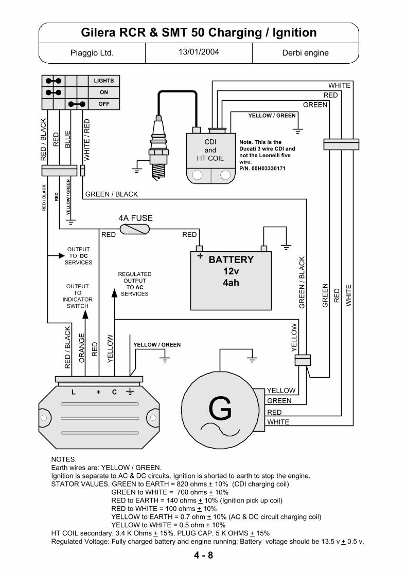
13/01/2004Piaggio Ltd. Derbi engine
Gilera RCR & SMT 50 Charging / Ignition
BATTERY12v4ah
+
L + C
OFF
ON
LIGHTS
G
OUTPUTTO
INDICATORSWITCH
OR
AN
GE
YE
LLO
W
4A FUSE
YELLOW
RE
D /
BLA
CK
REDRED
RE
D
RE
D /
BLA
CK
RE
D
BLU
E
WH
ITE
/ R
ED
GR
EE
N /
BLA
CK
RE
D
GR
EE
N
WH
ITE
YE
LLO
W
GREEN
GREENRED
WHITE
REGULATEDOUTPUTTO AC
SERVICES
OUTPUTTO DC
SERVICES
GREEN / BLACK
NOTES.Earth wires are: YELLOW / GREEN.Ignition is separate to AC & DC circuits. Ignition is shorted to earth to stop the engine.STATOR VALUES. GREEN to EARTH = 820 ohms + 10% (CDI charging coil)
GREEN to WHITE = 700 ohms + 10% RED to EARTH = 140 ohms + 10% (Ignition pick up coil) RED to WHITE = 100 ohms + 10% YELLOW to EARTH = 0.7 ohm + 10% (AC & DC circuit charging coil) YELLOW to WHITE = 0.5 ohm + 10%
HT COIL secondary. 3.4 K Ohms + 15%. PLUG CAP. 5 K OHMS + 15%Regulated Voltage: Fully charged battery and engine running: Battery voltage should be 13.5 v + 0.5 v.
4 - 8
REDWHITE
CDIand
HT COIL
YELLOW / GREEN
YELLOW / GREEN
YELL
OW
/ G
REE
N
RED
RED
/ B
LAC
K
Note. This is theDucati 3 wire CDI andnot the Leonelli fivewire.P/N. 00H03330171

4 - 9
GILERA RCR 50 & SMT 50The RCR and SMT sre basically re-badged Derbi Sendas. The Senda has been produced inseveral versions. The RCR and SMT are as follows:No electric start.No carburettor heater.No radiator fan.The ignition system uses the three wire Ducati system, not the five wire Leonelli.Stator: 00H03300701Complete rotor / stator assy: 00H03301011CDI : 00H03330171
Main fuse is 4 amp. Next to battery.Sprockets are: front:13t Rear: 53tChain is: 130 linksNo neutral light.Lights are switched on from the ignition switch. Positions are:
Off + LockOffIgnitionIgnition + Lights
Indicator relay is part of the rectifier / regulator.Carburettor is: Dell OrtoMain jet is: #56 on early bikes and # 62 for 2005 onwardPart numbers for mirrors are:
Right hand (DX): ODN00H02205671Left Hand (SX): ODN00D02200671
OIL PUMP CABLE.2003 vehicles have the oil pump cable connected to the pump. Later vehicles may have thecable disconnected and the pump held slightly open by a wire spring clip. The reason for this isto prevent over oiling at full throttle when restricted. The spring clip gives an average of 1.4% oilmix. Slight over oiling at tick over and about 1% mix at full throttle. It is very important that agood quality FULLY SYNTHETIC 2 stroke oil is used. Do not be tempted to connect the cableunless you are de-restricting the bike when the cable MUST be connected and the pumpadjusted normally.
DE-RESTRICT.Piaggio’s advice is: Do not de-restrict for any reason.To improve top speed slightly:Drill four 3 mm holes in the restrictor at the engine end of the exhaust pipe and fit a larger mainjet #60 if your bike is an early one with a #56 fitted as standard.2005 onward the bikes have a #62 as standard, to improve change the needle to a #11 andlower it by one notch. The #62 jet should be OK.Or to fully de-restrict:Remove restrictor tube from engine end of the exhaust pipe.Increase main jet about four sizes.Raise needle one notch.Adjust slow running mixture, it is air bleed so screw in to richen.Re-set idle speed to about 1900 rpm.The extra power will allow the bike to pull higher gearing, you should fit a z=14 front sprocket,p/n: 00H02805371.Italy suggests fitting a one step colder plug but I doubt that we need to do this.

5 - 1PIAGGIO LTD 14/10/03
X9 RANGE.CHANGING THE ODDOMETER DISPLAY TO SHOW MILESThis should be done at PDI. See manual 594284. Pages 9-4 and 4-571. Press and hold the TRIP and M buttons.2. Turn on the ignition.3. Release the buttonsThe display will now show “miles”.
SERVICE LIGHTSThe time and date functions should be set at PDI to ensure that the service lightswill come on at the correct time. Service Station Manual 594284 4-61 and ownershand books have details for setting the clock.
RE-SETTING THE SERVICE LIGHTSIf one or more of the service lights is flashing follow this procedure:1. Remove the central panel between the headlights, this is retained by 5 cross
head screws.2. You will find a button above the headlight unit marked “RES”3. Turn on the ignition. One of the three service lights is flashing.4. Briefly press the button. The light before the one you want to reset should light.5. Press and hold the button. The light you want to reset will start flashing faster.
While it is flashing fast release the button. Now the light should have gone out.6. Turn off the ignition and turn back on to prove the light has been cancelled.
If you have another light to reset; repeat the above steps.
If when you briefly press the button the light that comes on is not the one beforethe one you want to reset then briefly press the button again to make the lightscroll along.
Wiring to the “RES” button is Grey/Green and Black. Grey/Green goes to thedigital instrument panel and Black is to earth.
Service Station Manual for125/180 (594284 1st
update) page 4-59 hascomplete details.
Service Station Manual for500 chassis (594523) page4-15 has complete details.

5 - 2Piaggio Ltd. 14/10/03
X9 UNDER THE FRONT PANEL
The front panel between the headlights is retained by five cross head screws.Remove the panel to access the service light reset button and the two headlight relays.It is not necessary to remove the panel to adjust the headlight beam. The adjuster screw can beaccessed through the small grill near the top of the panel.
SERVICE LIGHTSThe time and date functions should be set at PDI to ensure that the service lights will come on at thecorrect time. Service Station Manual 594284 4-61 and owners hand books have details for settingthe clock.
RE-SETTING THE SERVICE LIGHTSIf one or more of the service lights is flashing follow this procedure:1. Turn on the ignition. One of the three service lights is flashing.2. Briefly press the button. The light before the one you want to reset should light.3. Press and hold the button. The light you want to reset will start flashing faster. While it is
flashing fast release the button. Now the light should have gone out.4. Turn off the ignition and turn back on to prove the light has been cancelled.
If you have another light to reset; repeat the above steps.If when you briefly press the button the light that comes on is not the one before the one you wantto reset then briefly press the button again to make the light scroll along.
Wiring to the “RES” button is Grey/Green and Black. Grey/Green goes to the digital instrumentpanel and Black is to earth.

Piaggio Ltd. 16/10/03
STATOR COIL VALUESRefer to the relevant Service Station Manual / wiring diagram
Vehicle Ign. Pick Up Ign. Charging AC Circuit DC Circuit50cc 2T Red - White
88 Ω (± 5 Ω)Green - White970 Ω (± 50 Ω)
Blue / Grey - Earth25 - 30v AC
Yellow - Blue25 - 30v AC
Red - Battery Positive1.5 - 2 amp (charged bat.=13v)
50cc 2TPurejet
Red - BrownValue not quoted
n/a n/a Any yellow - yellow 0.7 - 0.9 Ω Yellow to earth = no continuity
Runner 125Hexagon 2T
Red - Brown90 - 140 Ω
Green - White50 - 150 Ω
n/a Yellow - Yellow 27 - 30v AC
Liberty 125ET4 original
Red - Brown100 - 130 Ω
Green - White300 - 400 Ω
Blue / Grey - Earth25 - 30v AC
Yellow - Red26 - 30v AC
Red - Battery Positive1.5 - 2 amp (charged bat.=13v)
Skipper 2TTyphoon 125
Red - Brown90 - 140 Ω
Green - White100 - 160 Ω
n/a Yellow - Yellow 27 - 30v AC
Leader (all)125 / 180
Green - Black105 - 124 Ω
n/a n/a Any yellow - yellow 0.7 - 0.9 Ω Yellow to earth = no continuity
Hexagon 250GT & GTX
Green / White - Blue / Yellow50 - 170 Ω
n/a n/a Any yellow - yellow 0.1 - 1.0 Ω Yellow to earth = no continuity
X9 250 White / Yellow - Yellow>< 200 Ω
n/a n/a Any yellow - yellow >< 0.6 Ω Yellow to earth = no continuity
X9 500B 500Nexus
Engine speed & position sensorGreen-Black = 680 Ω ± 15%
n/a n/a Any yellow - yellow 0.2 - 1.0 Ω Yellow to earth = no continuityBattery charge > 20amps, lights on, high revs.
PX125 / 200 Red - White 90 - 140 Ω
Green - White 800 - 1100 Ω
Blue - Earth26 - 30v AC
Ammeter between red and battery positive.1.5-2 amps @ 3000 rpm. (charged battery. i.e. 13v)
Test to be carried out with the stator un-plugged and engine stopped. Test to be carried out with rectifier / regulator disconnected and engine running. Test to be carried out with rectifier / regulator and battery disconnected. Test with unit unplugged.
5 - 3

5 - 41of 3
Piaggio Ltd. August 2002
Piaggio, Vespa, GileraAUTOMATIC CHOKE OPERATION
The automatic choke units used on Piaggio scooters are all basically the same and all work in thesame way.Remember that the choke defaults to being ON so it is unlikely that a cold starting problem is dueto a malfunctioning choke.
Operation.• The choke unit has a plunger that is pushed down to close off a hole at the bottom of a drilling
in the carburettor. • A wax pellet is heated electrically and expands, as it heats up it pushes out the plunger. As the
wax warms the electrical resistance measured across it increases until it becomes open circuit.In most circumstances the choke will then remain off purely by the heat of the engine.
• The time taken for the choke to turn off is controlled only by the rate at which the wax expands.The ambient temperature will affect the time taken for the choke to turn off. Cold weather willmean the choke stays on longer etc.
• The choke is activated once the engine has started and not when the ignition is turned on.
50 & 80 cc two stroke engines.These scooters have headlights that are run from 12 volts AC.12 volts AC is used to operate the choke. AC can only be supplied when the engine is running sothe choke can not begin to turn off until the engine is running.
125 & 180 cc two stroke engines.These engines have an all 12 volt DC system.When the ignition is turned on there is 12 volts supplied to the choke but the circuit is notcompleted to earth and no current can flow. So the choke will not turn off if the ignition is left onbefore starting the engine.When the engine starts the rectifier / regulator completes the circuit to earth (via the grey wire) andthe choke will turn off during the next few minutes.
125 four stroke engines. (not Leader)Sfera 125 uses an AC system like the 50 / 80 cc engines.ET4 employs a relay so that the choke will be powered by DC but is triggered by the AC supplywhen the engine starts.
Leader four stroke engines.These engines have an all 12 volt DC system.When the ignition is turned on there is 12 volts supplied to the choke but the circuit is notcompleted to earth and no current can flow. So the choke will not turn off if the ignition is left onbefore starting the engine.When the engine starts the CDI unit completes the circuit to earth (via the white / black wire) andthe choke will turn off during the next few minutes.
50 four stroke.Connected to the AC output from the rectifier / regulator so power is only available when theengine is running.
250 Hexagon & X9 250 (Honda engines).AC powered by one of the three phase (yellow) wires direct from the generator.

5 - 42of 3
Piaggio Ltd. August 2002
Injected Engines.Injected engines do not need a choke because the ECU monitors the ambient air temperature andengine temperature and will apply a suitably rich mixture when needed. Faults.The most likely fault is the choke remaining ON. Symptoms will be anything that may be caused bya rich mixture. 1. High fuel consumption.2. Black spark plug.3. Rough running when hot. OK when ridden hard but rough and four stroking at 20 mph.4. Fails to start. Plug is found to be black and fouled.
To check the choke unit is operating.Refer to diagram 1.1. Remove choke unit from the carburettor.2. Measure the distance the plunger is protruding from the body, when it is cold.3. Attach a 12 volt battery to the socket and leave it for a two or three minutes.4. The plunger should have extended by 4-5 mm.5. Disconnect the battery.6. The plunger should retract slowly over a couple of minutes.
Dia.1. Choke unit operation.
To check the choke circuit.Refer to diagram 2.1. Follow wire from the choke unit until you find a grey two 2. Resistance check will confirm continuity through the chok3. To prove the choke circuit. Connect a voltmeter across the
engine running you should have 12-14.5 volts (AC or DC notes above). If no voltage then the choke will not turn off
Note. Remember that the choke defaults to being ON. If the chwill be a black and fouled plug. Or; The scooter starts and idleriding slowly (15 - 20 mph) the engine runs very roughly.
Connected toa 12v battery
Plunger has extended by4 – 5 mm
after a couple of minutes
Choke unit “cold”Note position of
plunger
pin plug and socket. Unplug.e unit. two pins of the socket. With thedepending on the engine type, see the.
oke does not turn off the symptoms ok and runs at speed ok. When

5 - 43of 3
Piaggio Ltd. August 2002
Dia.2. Choke unit power supply.
Note. Choke units all look much the same but are different and itchoke in the correct carburettor.
VΩResistance will vary dependingon the temperature of the chokeunit. When cold = 35 ± 5 ohm.
DC powered choke1. Ignition off = 0 volts2. Ignition on = 12 volts3. Engine run = 13-14.5
12-14.5 (AC or DC) voltsonly when engine is
running
Choke
V
is important to use the correct
volts

14/10/2003Piaggio Ltd Piaggio Ltd
Fuel Gauge & Sender Circuit
A C B
Float
Top view of fuel sender unit socket
The fuel sender units on our automatic scootersmay look different but the circuit and method of
operation is always basically the same.
Vehicles without a fuel gauge have a low fuelwarning light. They will have a two pin wiringconnector. The wiring logic will be the same.
Remember that the power is supplied to theinstrument panel and the tank unit is earthing itrather than sending power to the instruments.
WIRINGA = BLACKB = GREEN / YELLOWC = GREEN / WHITE
TESTSA - CLow fuel level >< 100 ohmsHigh fuel level >< 3 ohms
A - BLow fuel level = 0 ohmsHigh fuel level = open circuit
FUEL
12v DCSupply
Fuel GaugeLow fuelwarning
Low Fuel Switch
5 - 5
A
B
C

5 - 61 of 3
Piaggio Ltd. 25/05/04
INSTRUMENT PANEL DISPLAYSeveral Piaggio vehicles now have electronic instruments. Please make sure you are familiar withtheir operation and settings.
B (Beverly)
Clock and trip counter will re-set if voltage drops below 4,5v. Total distance record is “non-volatile” and can not be affected.Changing the oddometer display to show miles.1. Ignition off2. Press and hold down the MODE and CLOCK buttons3. Turn on the ignition4. Miles or Km will be displayed to show which is selected. Turn off and start again to change it
DNA
Changing Km/h speedo and Km distance to MPH and Miles.This should be done at PDI. See Service station Manual. Originally the manual said that thechange can only be made if less than 6km show on the total distance. This is no longer true, thechange can be made as often as needed at any distance.
1. Press and hold down the MODE and CLOCK buttons.2. Turn on the ignition. The display will remain blank.3. Wait until the display shows the letters “MPH”. Then you can release the buttons.4. Wait for the instrument to go through the normal start up and you will notice that it now
displays MPH.
ICE
Changing Km/h speedo and Km distance to MPH and Miles.This should be done at PDI. See Service station Manual.
1. Press and hold down the MODE and CLOCK buttons.2. Turn on the ignition. The display will remain blank.3. Wait until the display shows the letters “MPH”. Then you can release the buttons.4. Wait for the instrument to go through the normal start up and you will notice that it now
displays MPH.
Nexus 500Clock.
The clock time and date functions MUST BE SET AT PDI. Because the service iconintervals are controlled by time as well as mileage.
Changing the oddometer display to show miles.This should be done at PDI.
1. Press and hold the TRIP and M buttons.2. Turn on the ignition.

5 - 62 of 3
Piaggio Ltd. 25/05/04
Nexus cont.Service icons.There are two icons on the display to remind the owner that certain servicing is due. These iconsare controlled by elapsed mileage and elapsed time so it is important to set the date and timecorrectly at PDI. If you do not do this you may find the icons come on at the wrong time (and youwill get a grumpy customer).SERVICE: Comes on after first 1000km and then after every 6000km.
This light also comes on after one year even if the distance has not been covered.BELT: Comes on after every 12000km.
Re-setting service icons.If one or both of the service icons is flashing follow this procedure:
1. Press "MODE" and "ODO/SET" buttons at the same time. Keep pressing the buttons and turnon the ignition, after about 3 seconds, the two icons icon will light. Release the buttons.
2. Press the “MODE” button briefly (for less than 1 second) to select the icons in a sequence.The selected icon must turn on with a solid light.
3. Press the “MODE” button for more than 3 seconds to reset the selected icon;Note that the “SERVICE” function also resets the date.
Don’t forget to reset service icons when you do a service, even if they are not flashing(scooter has come in early). If you do not do it the customer will be back in a few days withan icon flashing. That makes you look bad and again you have a grumpy customer.
X9Clock.
The clock time and date functions MUST BE SET AT PDI. Because some of the servicelight intervals are controlled by this.
Changing the oddometer display to show miles.This should be done at PDI. See Service Station Manual.
3. Press and hold the TRIP and M buttons.4. Turn on the ignition.5. Release the buttons
The display will now show “miles”.
Service lights.There are three lights on the display to remind the owner that certain servicing is due. Theselights are controlled by elapsed mileage and elapsed time so it is important to set the datecorrectly at PDI. If you do not do this you may find the lights come on at the wrong time (andyou will get a grumpy customer).OIL: Comes on after first 1000km (625 miles) and then after every 3000kmSERVICE: Comes on after first 1000km and then after every 6000km.
This light also comes on after one year even if the distance has not been covered.BELT: Comes on after every 18000km.

5 - 63 of 3
Piaggio Ltd. 25/05/04
X9 cont.
Re-setting service lights.If one or more of the service lights is flashing follow this procedure:1. Remove the central panel between the headlights, 5 cross head screws retain this.2. You will find a button above the headlight unit marked “RES”3. Turn on the ignition. One of the three service lights is flashing.4. Briefly press the button. The light before the one you want to reset should light. If the
light that comes on is not the one before the one you want to reset then briefly press thebutton again to make the light scroll along. When you have the light before alight, then:
5. Press and hold the button. The light you want to reset will start flashing faster. While it isflashing fast release the button. Now the light should have gone out.
6. Turn off the ignition and turn back on to prove the light has been cancelled.
If you have another light to reset; repeat the above steps.
Don’t forget to reset service lights when you do a service, even if they are not flashing(scooter has come in early). If you do not do it the customer will be back in a few days with alight flashing. That makes you look bad and again you have a grumpy customer.
It is probably worth going through the re-set procedure for all three lights at PDI because ifthe battery had been connected previously the counter will have started from the wrong day.
ZIPThe Zip now has electronic instruments. The speedometer is still the traditional analoguedisplay but it is now electronically controlled. The odometer is now digital LCD. It issupplied showing the distance in Km. It can be changed to show miles but only if it ischanged during the first 10km. CHANGE IT AT PDI.
Changing the oddometer display to show miles.1. Ignition off2. Press and hold the button on top of the leg shield.3. Turn on ignition. LCD display will show “Cont” (km) or “EnGL” (miles)4. Briefly press button to toggle between the two alternatives.5. When the correct press and hold the button for more than one second.6. Turn ignition off. Turn back on to confirm the setting is now correct.
Re-setting the “Change Oil” warning.At 6000km an oil change warning will be displayed on the LCD display for 10 seconds everytime the ignition is turned on. Cancel this at service.1. Press and hold the button at top of the leg shield.2. Turn ignition on.3. Release button and turn ignition off. Turn ignition back on to check that the warning has
been cancelled.

01/02/2006Piaggio Ltd
Remote Seat Release
Vehicles now fitted with remote seat release.X8 X9 500 evo Nexus
Replacing the remote control key battery and adding new keys.Battery is a CR1616
To zero the control unit.1. Remove the front shield to access the saddle opening reception/control unit.2. Two cables protrude from the electric wiring, one is black (earth) and the other is black-blue (Nexus & X9) or white (X8) from Pin 3 of the controller.3. Connect the two cables for at least 10 seconds to delete all remote controls stored in the controller.
To program the remote control : Nexus1. Insert the ignition key (do not turn on).2. Press and hold the remote control button. Turn the key to ON, release the button, return the key to OFF within 4 seconds.3. Wait 1 to 8 seconds4. Repeat steps 2 and 3 for 4 times more without removing the key. The control unit will open the saddle to confirm the successful programming.- You can program up to 7 remote controls by the above procedure.
To program, the remote controls, X9 500 evo and X81. Insert the ignition key, switch to «ON» for 1 to 3 seconds, then set it to «OFF».2. Within 10 seconds, reset the switch to «ON» and within 3 seconds, press the remote control button, then set to «OFF» again.3. If the saddle opens with this last operation, the programming was successful.- You can program up to 7 remote controls by the above procedure.
1. Aerial - violet2. Seat actuator3. Reset4. +12v6. +12v switched7. Earth - black10. Trunk actuator11. Pre-wiring for alarm (X8 & X9)12. Pre-wiring for alarm (X8 & X9)
5 - 7

5 - 8Piaggio Ltd. 01/02/06
Setting the clock.
Any Piaggio / Gilera / Vespa scooter with a separate two button clock.
A
B
The clock should be displaying the hours and minutes with the two dots flashing.
Press button A once and the month and day will be displayed for about five seconds.
Press and release button B once and the clock will alternately display the day and month and
then the hour and minute.
Press and hold button B and you can set the month by pressing button A repeatedly until the
correct month is displayed. Release button B
Press and hold button B again and you can set the day by pressing button A repeatedly until
the correct day is displayed. Release button B
Press and hold button B again and you can set the hours by pressing button A repeatedly
until the correct hour is displayed. Release button B
Press and hold button B again and you can set the minutes by pressing button A repeatedly
until the correct minutes are displayed. Release button B
Press and release button B again and it will return the display to the normal hours and
minutes.
To return to the normal display at any time repeatedly press button B until the normal display
is shown.
3 : 29

16/10/2003Piaggio Ltd. Piaggio Ltd.
TYPHOON 80 - 125 FUEL SYSTEM
Pump driven by crankcase depression
PumpOne wayvalve
Auxiliary tank vent
Balance pipe
Front tank Main tank
Vacuumtap
Supply tocarburettor
Ventcontrolvalve
Vent toatmosphere
Typhoon 80 and 125 have an auxiliary fuel tank located under the front panel. Theplumbing for this fuel system looks complicated. The Typhoon parts catalogue contains aillustration which should help you locate the components on the vehicle. The diagramabove is intended to help explain the operation of the system and should prove useful whenfault finding.VENT TO ATMOSPHERE The system has only one vent which you will find exiting underthe rear mudguard.VENT CONTROL VALVE Controls venting to prevent loss of fuel from full tank. Air canenter the tank without restriction but a slight pressure is required before vapour can exit.AUX TANK VENT Auxiliary tank vents to the main tank via a pipe that has to run under thefoot boards. Because this pipe gets lower than the tank level it can become full of fuel andso the auxiliary tank will not vent. To prevent this a limited flow ONE WAY VALVE allowsany fuel to be sucked out.A large diameter BALANCE PIPE lets petrol flow between the two tanks.A smaller diameter pipe passes through the PETROL PUMP which pumps petrol from theauxiliary tank to the main tank.Petrol PUMP is driven by the vacuum/pressure pulses from the crank case.Note that the BALANCE PIPE stands up into the main tank so once the fuel level reachesthat point the pump will drain the auxiliary tank and all the remaining fuel will be in the maintank. Because of this layout the fuel gauge does not drop at a steady linear rate. If you startwith a full tank, fuel is used in the following three phases:1. Fuel used from main and auxiliary tanks equally - Gauge will drop from full to ¼ .2. Level remains constant in main tank while auxiliary is drained - Gauge remains at ¼ .3. Fuel is used only from main tank - Gauge drops from ¼ to empty.VACUUM TAP is operated by vacuum from the inlet manifold.
6 - 11 of 2

16/10/2003Piaggio Ltd. Piaggio Ltd.
TYPHOON 80 - 125 FUEL SYSTEM
If you suspect that the fault is due to lack of fuel. Firstly prove that the carburettor isrunning out of fuel.Attach a piece of clear tube to the float bowl drain and turn it up the side of thecarburettor.Open the drain screw. you will now be able to view the fuel level. It should remain about3.5mm below the float bowl joint. If you find it is low or it drops during running then youshould explore the fuel supply.
If you have a problem that suggests a poor supply of fuel to the carburettor.1. Check that you have fuel in the main tank. If you have fuel then you can forget about the front tank and its associated plumbing, this can not affect the supply to the carburettor.
Not able to get 7 litres of fuel in scooter with a nearly empty tank. Auxiliary tank is not being used for some reason.1. Check pump. With engine running you should see the pumped fuel coming out of the pipe in the main tank.2. Check for pinched pipes particularly under foot boards and helmet compartment.3. Check auxiliary tank vent is clear of fuel (one way valve not working).
Scooter cuts out probably through lack of fuel.1. Check vent pipe is clear. Blow through it with filler cap removed.2. In the vent pipe you will find a grey and orange valve. This is a flow control valve. It should offer no resistance to air entering the tank and some resistance should be felt if you blow through it from the tank side. Do not drill a hole in the filler cap to cure a venting problem.
Fuel comes out of vent when scooter is parked in sun or on a slope.1. Vent pipe valve is faulty.2. Early 80's did not have this valve, a modification kit is available from Piaggio.
Scooter runs ok on bench but customer says it cuts out when ridden.1. Pipe trapped under helmet compartment is squashed by weight of rider.
FAULT FINDING
6 - 12 of 2

16/10/2003Piaggio Ltd. PAGE 1 OF 2
DNA FUEL SYSTEM
Early DNA125 / 180
VACUUM FROMMANIFOLD
WHITE PLASTICFUEL PUMP
NONRETURNVALVE
FUEL FILTER
OVER RUNVALVE180 only
TANKVENT
FUEL TANK
125 / 180 NOTES:1. No vacuum tap is fitted.2. Fuel pipes are clear plastic. Vacuum pipes are black rubber.3. Pump is driven by inlet manifold vacuum. not crankcase vacuum/pressure.4. Supply to carburettor is pressurised.5. DNA 125 is the same but without the over run valve.
DNA 125 / 1802001>
VACUUM FROMMANIFOLD
WHITE PLASTICFUEL PUMP
NONRETURNVALVE
FUEL FILTER
OVER RUNVALVE180 only
TANKVENT
FUEL TANK
125 / 180 NOTES:1. Vacuum tap is fitted to main tank.2. Fuel pipes are clear plastic. Vacuum pipes are black rubber.3. Pump is driven by inlet manifold vacuum. not crankcase vacuum/pressure.4. Supply to carburettor is pressurised.5. DNA 125 is the same but without the over run valve.6. DNA 180 over run valve was deleted during early 2002
VACUUMTAP
6 - 2
See Note 6.

16/10/2003Piaggio Ltd. PAGE 2 0F 2
DNA FUEL SYSTEM
Later DNA 50
METAL BODIEDFUEL PUMP
CRANKCASEPRESSURE /VACUUM
TANKVENT
MAIN FUEL TANK
MANIFOLDVACUUM
Later 50 NOTES:1. Carburettor is pressure fed.2. Fuel pipes are clear plastic. Vacuum pipes are black rubber.3. Pump is driven by crankcase vacuum/pressure. Not manifold vacuum4. Slow running adjustment is "air bleed". Turn in to richen
VACUUM TAP
Early DNA 50HEADER TANK
VACUUM TAP
METAL BODIEDFUEL PUMP
CRANKCASEPRESSURE /VACUUM
TANKVENT
MAIN FUEL TANK
MANIFOLDVACUUM
RETURN TO TANK
Early 50 NOTES:1. Carburettor is gravity fed not pressure fed.2. Fuel pipes are clear plastic. Vacuum pipes are black rubber.3. Pump is driven by crankcase vacuum/pressure. Not manifold vacuum4. Slow running adjustment is "air bleed". Turn in to richen
6 - 2

6 - 3Piaggio ltd. August 2001
HEXAGON EXS1T fuel system.
All Hexagons have a pressurised fuel supply. The original EXS1T had a feed direct from the pump to the carburettor. Most
EXS1T Hexagons have the system shown here. The return line from the header tank to the main tank is only there to allow the
header tank to fill up. The connection in the header tank has a very small holein it so air can escape but the system pressure will be maintained. It is veryimportant that this hole is not enlarged.
If system pressure is lost the scooter will still run but the mixture will now be veryweak.
The carburettor should be fitted with a float needle seat marked #1 todenote a 1mm hole. If a seat with a larger hole is used the float will not beable to shut off the fuel. The carburettor will flood and the engine will run rich.
HEADER TANKVENTING PIPE
CRANKCASE
FILTERPUMP
CARBURETOR
HEADER TANK
MAIN TANK

6 - 41 of 3
Piaggio Ltd. 06/01/06
PUMPED FUEL SYSTEMSExplanation of differences on Piaggio and Gilera scooters
These scooters all have a carburettor and pumped fuel supply:
B 125DNA 50.DNA 125.DNA 180.Hexagon 125.Hexagon 125 LX.Hexagon 180 LXT.Hexagon 250 GT.Hexagon GTX 125
Runner 50Runner FX.Runner FXRRunner VX.Runner VXR.Typhoon 80Typhoon 125
Vespa GT 125 / 200X8 125 / 200X8 250 X9 125.X9 250.
B 125 / 200 All have a pressurised fuel system.Pump operates from the inlet manifold vacuum.Pump is near the tank and supplies fuel directly to the carburettor via an inline fuelfilter and a non return valve.
DNA 50 2 stroke. TWO different fuel systems.EARLY VEHICLES: Do not have a pressurised fuel system.The pump operates by crankcase pressure/vacuum. It feeds fuel to a header tankthat supplies the carburettor by gravity. Normal vacuum tap in header tank operatedby vacuum from inlet manifold.The return from the header to the main tank is not restricted and fuel circulatesfreely.If the header tank is not full then a fuel supply problem must be suspected.LATER VEHICLES: Have a pressurised fuel system.The pump operates by crankcase pressure/vacuum. It feeds fuel directly to thecarburettor.A vacuum tap is fitted to the bottom of the tank. This is opened by inlet manifoldvacuum.
DNA 125 / 180 4 stroke. All have a pressurised fuel system.Pump operates from inlet manifold vacuum.Pump is attached to the bottom of the tank and supplies fuel directly to thecarburettor via an inline fuel filter and a non return valve.From late 2001 all vehicles had a vacuum tap fitted to the bottom of the tank. Thetap is connected by a “T” piece to the vacuum pipe near the fuel pump.Note that the early 180 also uses the vacuum line to supply vacuum to an over runvalve on the carburettor.

6 - 42 of 3
Piaggio Ltd. 06/01/06
HEXAGON 2 stroke. All have a pressurised fuel system. Pump operates bycrankcase pressure/vacuum.EXS1T early. Pump supplies fuel directly to the carburettor.EXS1T late. Same as early system but with a header tank to ensure a head of fuelto help starting after a period. The header tank has a return pipe, the connector onthe tank has a very small hole so system pressure is maintained, it is important thishole is not enlarged.ZAPM05000 (125). Pump supplies fuel directly to the carburettor.ZAPM06000 (180). Same as 125 but with a limited flow return that controls thesupply pressure. This is a “T” piece in the carburettor supply pipe and a pipe thatreturns to the tank, there is a restrictor in that pipe to limit the return and maintainthe system pressure.Refer to the separate sheet for a more detailed explanation (Hexagon LX / LXT fuelsystem)
HEXAGON 4 stroke. All have a pressurised fuel system.GTX 125 / 180. Pump operates from inlet manifold vacuum.Fuel is pumped direct to the carburettor.GT 250. (Honda engine) Electrically operated pump that is controlled by the ECU
RUNNER 2 stroke. Do not have a pressurised fuel system.The pump operates by crankcase pressure/vacuum. It feeds fuel to a header tankthat supplies the carburettor by gravity. Normal vacuum tap in header tank, vacuumfrom inlet manifold.The return from the header to the main tank is not restricted and fuel circulatesfreely.If the header tank is not full then a fuel supply problem must be suspected.
RUNNER 4 stroke. All have a pressurised fuel system.Pump operates from inlet manifold vacuum.Pump is attached to the bottom of the tank and supplies fuel directly to thecarburettor via an inline fuel filter and a non return valve.Note that the 180 also uses the vacuum line to supply vacuum to an over run valveon the carburettor.
TYPHOON 80 & 125. Do not have pressurised feed to the carburettor.They have a second tank under the front panel to increase the capacity.Fuel is pumped from the front (auxiliary) tank into the rear (main tank). The rear tankfunctions like all conventional gravity feed systems.The system is not pressurised and fuel will circulate freely between front to reartank until the front tank is empty and the rear tank is about half full.If the pump / front tank system fails the only problem is that the scooter will have areduced fuel capacity.Refer to the separate explanation sheets for more detailed operation and faultfinding information. (Typhoon 80-125 fuel system & Typhoon 80-125 fuel systemfault finding)

6 - 43 of 3
Piaggio Ltd. 06/01/06
VESPA GT 125 / 200 All have a pressurised fuel system.Pump operates from the inlet manifold vacuum.Pump is near the tank and supplies fuel directly to the carburettor via an inline fuelfilter and a non return valve.
X9. All models have a pressurised fuel system.
X9 125. Leader Engine.Pump is operated by inlet manifold vacuum. Fuel is supplied directly to thecarburettor.
X9 250. (Honda engine)Electrically operated pump that is controlled by the ECU. Fuel is supplied directly tothe carburettor.
X9 250. Quasar Engine. Have a pressurised fuel system.Pump operates from inlet manifold vacuum.Pump is near the tank and supplies fuel directly to the carburettor via an inline fuelfilter and a non return valve.

16/10/2003Piaggio Ltd. Piaggio Ltd.
VESPA PX FUEL TAP
Viewed from above. ie Sitting on the scooter
CLOSED
OPEN
RESERVE
6 - 5

1 of 3Piaggio Ltd. 06/01/04
FITTING NEW MAIN BEARINGS TO TWO STROKE AUTO’SReplacing the main bearings is not a difficult job but it MUST be done the correctway to ensure success.The problem can be that you do not achieve the correct end float in the crank sothe bearings are being side loaded. This will cause a bearing failure within a veryshort time (200 miles max!)It is vital that the end float is checked with a dial gauge once the cases havebeen bolted together.
The following assembly procedure is the best way to do the job. It is the quickestand easiest. Also it almost guarantees correct tolerance. Please do it this way:
1. Heat the bearings in engine oil. First signs of smoke from the oil is hot enough!About 100 degrees
2. Support the crankshaft vertically. Drop one bearing onto crank. If it will not dropon (by gravity) it is not hot enough. If you have to tap it home, ONLY use apiece of tube to act on the centre race. NEVER hit the outer race. Once it is onleave it to cool.
3. Turn crank over and drop other bearing on. Leave it to cool completely.4. Position the drive side crankcase half on its side with inside facing up. Support it
on blocks of wood so the crank can be dropped in (again, just using gravity).1

2 of 3Piaggio Ltd. 06/01/04
5. Heat the case with a hot air gun, mostly heat it around the area where thebearing will fit. Don't try to hurry this. It is hot enough when the rear end of thecase is too hot to keep you hand on.
6. When it is hot enough then drop the crank / bearing in and leave it to cool. If itwill not drop in easily then the case is not hot enough yet.
7. Once it is completely cold turn the case over so the crank is hanging down andthen fit the crank removal tool 20163Y (50cc) or 20262Y (125 & 180cc) as if youwere going to press the crank back out of the case.
8. Tighten the extractor bolt as tight as you can by hand. This will push the crankout against the bearing so all the free play in the bearing has been removedand the crank is pushed out as far as it can go. Do not use a spanner to tightenthe bolt or you may move the bearing. Tightening it by hand can not move thebearing (you ain't that strong). Now put the case back on it’s blocks of wood.

3 of 3Piaggio Ltd. 06/01/04
9. Heat the other (small) case half and prepare to drop it onto the crank / case.10. Fit the cases together with liquid gasket (not silicon). Don't forget the water
pump impeller on water cooled engines. Bolt it up and leave it to cool.11. Once it is completely cold remove the special tool. Now use a dial gauge to
measure the end float. Pull the crank one way, notice the gauge reading andthen push it the other way. You MUST have 0.03 - 0.09mm free play.
12. If you have nearly got the free play try tapping each end of the crank with anylon hammer and check again.
13. If you have not got enough free play there is no point carrying on. Take it apartand do it again (I would recommend using new bearings just in case the othershave been damaged!).
The reason for establishing the end float is to ensure that there is no side load onthe bearings. Ball races do not like side load and they will fail very quickly.Checking the free play guarantees that the bearing is not side loaded and theballs can run centrally in the bearing tracks.
The benefits of this method include: We only heat each part once. No wasted time re-heating We only used gravity to fit it together. No risk of damage and it must be
together properly. The bearings have only been heated in oil. No risk of damage.
Please do not try and improvise. Make sure you have all the correct tools for thejob. They are a very good investment for time saved and stress avoided.
If you have any questions please give your Regional After Sales Manager a call.
3

Piaggio Ltd. May 2000
PX 200 / 125 “COSA” TYPE CLUTCHThe COSA type clutch is now fitted to the PX 200 & PX125.
It can replace the old type clutch as a complete assembly. p/n 433548 (200cc) p/n 288650 (125cc)
2
Plain. p/n: 237272 qty. 1Thick plate with shallow splines
Output gear. p/n: 433547 (200cc) p/n: 286899 (125cc)
Plain. p/n: 237271 qty. 1Dished plate with two notched splines
Plain. p/n: 286782 qty. 2Two the same
Cork on one side. p/n: 237268 qty. 1Plain side against circlip
Cork on both sides. p/n:237267 qty. 3Three the same
Circlip. p/n: 038477Springs. p/n: 289603 qty. 8 (200cc) p/n: 289607 qty. 8 (125cc)
Clutch body. p/n: 237362
Hexagonal nut. p/n: 015222Use 19mm socket
On the crankshaft, behind the clutch is the oil pumpdrive gear p/n: 287038.It is important that this is fittedthe correct way round, as shown.
Wavey washer.p/n: 006982
Clutch centre & bush. p/n: 285079This is keyed to the crankshaft
GEAR
NOTECHAMFER
CRANKSHAFT

3Piaggio Ltd. August 2001
PISTONS AND SMALL END BEARINGS
Small End Bearing sizes.Small end needle roller bearings fitted to two stroke twist and go engines and PXengines are supplied in four sizes they are colour coded for identification.The end of the con rod will either be colour coded or it will be marked with aseries of lines.
Bearing colour Con rod markingCopper I
Blue IIWhite IIIGreen IIII
Parts catalogues will show four partnumbers the lowest number will bethe first in this list.
Service Station manuals specify thecon rod small end diameters so youcan determine the correct bearingsize by measurement.
Piston sizes.Piaggio use alloy or cast iron barrels on different engines. Alloy barrels can notbe re-bored and over size pistons are not available. Oversize pistons areavailable for cast iron barrels. These are listed as 1M, 2M, 3M.In addition to oversize there will be four pistons listed for all engines as “FC” orFC1, FC2 etc. These are tolerance fittings.Pistons can be matched to barrels in two ways. Either by referring to thetolerance data page near the front of the appropriate Service Station Manual orby referring to the marking on the crown of the piston and the top of the barrel.On some engines barrel and piston will both have a letter stamped into them.Both letters should match. The lowest (first) part number will be the smallest pistonand first in this list.
Piston marking SizeE FC 1F FC 2G FC 3H FC 4
Remember, if you are measuring barrel and piston you should always measure inline with the gudgeon pin because they will have worn oval. Most wear occursat right angles to the gudgeon pin.

07/08/2002Piaggio Ltd. Typhoon / Runner etc.
Up side down Forks
This design is typical for any Piaggio or Gilera modelusing up side down forks
Typhoon, Runner, SKP, Zip, Skipper ST, NRG etc.
Forks are grease filled for lubrication. The grease can be expected to work past the nylon bush so the chrome stanchion will get adirty ring round it.Damping is by a sealed hydraulic damper cartridge in the left leg. The cartridge is held at the bottom by a bolt that will be found in thebottom of the axle mounting. The top of the damper rod is held by a nut on top of the top yoke. If the seals in this unit fail you will findoil dripping from the bottom of the left leg.Some 50's did not have the damper. To check if a damper is fitted: look for the nut on top of the left leg, no nut means no damper.To separate the fork leg:1. Remove damper top nut (from left leg only).2. Remove the dust seal.3. Remove the bottom circlip.4. Pulling the stanchion hard will force the upper circlip out of the tapered groove, the circlip and bush will be pulled out.On very early forks the top circlip groove was not tapered so it will be necessary to pull the bush out to get to the circlip.To pull the bush out:1. Lubricate the bush with WD40 or similar.2. Carefully screw two small self tapping screws into the nylon bush and pull it out using two pairs of pliers.Note that there are several manufactures of these forks and although they look the same the internal components may not beinterchangeable between makes.
Damper Rod RetainingNut
Bolt retains the damperand axle support
Upper Circlip
Nylon Bush
Lower Circlip
Dust Seal
LEFT FORK LEG
Fork Leg
Tapered groove
Upper Circlip
Lower Circlip
Nylon Bush
Nylon Bush
Fork Stanchion
4

25/08/057-5
SPARK PLUGSPIAGGIO / VESPA mm NGK ChampionB 125 (Beverly) 125 four stroke 0.7-0.8 CR8 EB RG4 HCB 500 (Beverly) 500 four stroke 0.7-0.8 CR7 EKB RG6 YCCosa 125 , 150 0.6 B9 ES (BR9 ES) N2C (RN2C)Cosa 200 0.6 B7 ES (BR7 ES) N4C (RN4C)Fly 50 two stroke 0.5-0.6 RGN2CFly 125 Leader four stroke 0.8 CR9 EB RG4HCFree 50 (all versions) 0.5-0.6 BR9 ES RN2CHexagon 125 &180 two stroke (all versions) 0.5-0.6 BR9 ES RN2CHexagon GT250 & GTX 250 (Honda 4 stroke) 0.8-0.9 DPR6 EA9Hexagon GTX 125 four stroke 0.7-0.8 CR9 EB RG4 HCLiberty 50 two stroke (all versions) 0.5-0.6 BR9 ES RN2CLiberty 125 four stroke (original version) 0.7-0.8 CR9 E RG4 HCLiberty 125 Leader four stroke 0.7-0.8 CR7 EB RG6 YCLiberty 125 Leader four stroke (heavy use) 0.7-0.8 CR8 EB RG4 HCLiberty 125 RST (2004>) Leader four strokeNRG 50 water cooled (heavy use) 0.5-0.6 BR10 ES RN1CNRG 50 (air or water cooled. All versions) 0.5-0.6 BR9 ES RN2CQuartz 50 0.5-0.6 BR9 ES RN2CSfera 125 four stroke 0.5-0.6 CR9 E RG4 HCSfera 50 & Sfera 80 (all versions) 0.5-0.6 BR9 ES RN2CSkipper ST 125 four stroke (all versions) 0.7-0.8 CR9 E RG4 HCSkipper 125 two stroke (all versions) 0.6-0.7 BR9 ES RN2CVelofax 50 two stroke 0.5-0.6 BR9 ES RN2CVespa 50 Special & PK50S 0.6 B6 HS L86Vespa ET2 50 two stroke (carburettor) 0.5-0.6 BR9 ES RN2CVespa ET4 50 four stroke 0.7-0.8 CR9 E RG4 HC. RG4 PHPVespa ET4 125 four stroke (all versions) 0.7-0.8 CR9 E RG4 HCVespa LX 50 four stroke 0.7-0.8 CR8EBVespa LX 50 two stroke 0.6-0.7 RGN2CVespa LX 125 four stroke 0.7-0.8 CR7EB RG6YCVespa GT 125 0.7-0.8 CR8 EB RG4 HCVespa GT 200 0.7-0.8 CR7 EB RG6 YCVespa GTS 250 injection 0.7-0.8 RG4 PHPVespa Primavera ET3 0.6 B7 HSVespa Primavera & PK 125 0.6 B6 HSVespa PX 125 0.5-0.6 B7 HS L82CVespa PX 200 0.5-0.6 B7 ES (BR7 ES) N4C (RN4C)Vespa T5 Classic 125 0.6 B9ES (BR9 ES) N2C (RN2C)X9 125 (Piaggio 4 stroke engine) 0.7-0.8 CR8 EB RG4 HCX9 250 evolution (Piaggio 4 stroke engine with carburettor) 0.7-0.8 CR8 EB RG4 HCX9 250 (Honda 4 stroke engine) 0.8-0.9 DPR7 EA9X9 500 (Piaggio 4 stroke engine) 0.7-0.8 CR7 EKB RG6 YCZip 50 four stroke 0.7-0.8 CR9 E RG4 HC. RG4 PHPZip 50 2 stroke (all versions, inc. catalytic) 0.6-0.7 BR9 ES RN2CZip 125 four stroke 0.7-0.8 CR7 EB RG6 YCGILERACoguar 125 (Honda 4 stroke engine) 0.8-0.9 DPR8 EA9DNA 125 & DNA 180 four stroke 0.7-0.8 CR8 EBDNA 50 two stroke (catalytic) 0.6-0.7 BR9 ES RN2CH@K & GSM 50 2 stroke (Gilera engine) 0.5-0.6 BR9 ES RN2CH@K & GSM 50 2 stroke (Derbi engine) 0.-0.ICE 50 two stroke catalytic 0.6-0.7 BR9 ES RN2CNexus 500 four stroke 0.7-0.8 CR7 EKB RC6 YCRCR 50 2 stroke (Derbi engine) 0.5 B9 ES (BR9 ES) N2C (RN2C)Runner VX125 & VXR180 four stroke 0.7-0.8 CR8 EBRunner VXR 200 four stroke 0.7-0.8 CR7 EKB RG6 YCRunner 50, 125 & 180 two stroke (all versions) 0.6-0.7 BR9 ES RN2CRunner 50 “Purejet” direct injection 2 stroke 0.6-0.7 RG6 YCAStalker & SKP 50 two stroke 0.5-0.6 BR9 ES RN2COLDER GILERA MOTORCYCLESSaturno 350 / 500 four stroke 0.6-0.7 DPR8 EA9 A5YCDakota 350 / 500 four stroke 0.6-0.7 DPR8 EA9 A5YCNordwest 600 four stroke 0.6-0.7 DPR9 EA9RC 600 four stroke 0.6-0.7 DPR8 EA9CX 125 & Apache & Crono & Free-Style 125 cc two stroke 0.6-0.7 B10 EG - BR9 EG N82 - C55GFR 125 two stroke 0.6-0.7 B10 EGV C55C

7-6 Oil list.xlsMake/Model Engine Gearbox Final Drive Forks Coolant
Vespa ET2 50 2 str. Synthetic 2 stroke API TC or higher - CVT - Gear 80W-90 light gear GL3 or higher 75cc sealed unit - Air -Vespa ET4 50 4 str. 5W-40 synthetic API SJ or higher 850cc CVT - Gear 80W-90 light gear GL3 or higher 80cc sealed unit - Air -Vespa LX 50 4t 4 str. 5W-40 synthetic API SJ or higher 850cc CVT - Gear 80W-90 light gear GL3 or higher 85cc sealed unit - Air -Vespa ET4 125 4 str. 20W-50 synthetic API SG or higher 850cc CVT - Gear 80W-90 light gear GL3 or higher 90cc sealed unit - Air -Vespa LX 125 & ET4 125 Leader 4 str. 5W-40 synthetic API SJ or higher 1 ltr. CVT - Gear 80W-90 light gear GL3 or higher 100cc sealed unit - Air -Vespa GT 125 & GT 200 4 str. 5W-40 synthetic API SJ or higher 1 ltr. CVT - Gear 80W-90 light gear GL3 or higher 150cc sealed unit - Ethelyne Glycol Cuna NC 956-16 2.1 - 2.5Vespa GTS 250 injection 4 str. 5W-40 synthetic API SJ or higher 1.3 ltr. CVT - Gear 75W-80 light gear GL4 or higher 250cc sealed unit - Ethelyne Glycol Cuna NC 956-16 2.1 - 2.5Vespa PX 125 / 150 / 200 2 str. Synthetic 2 stroke API TC or higher - 4 spd 80W GL4 or higher 250cc n/a - - sealed unit - Air -Piaggio B 125 & B 125 RST 4 str. 5W-40 synthetic API SJ or higher 1.1 ltr. CVT - Gear 80W-90 light gear GL3 or higher 250cc 10W 102cc Ethelyne Glycol Cuna NC 956-16Piaggio B 500 4 str. 5W-40 synthetic API SJ or higher 1.7 ltr. CVT - Gear 80W-90 light gear GL3 or higher 250cc 10W 233cc Ethelyne Glycol Cuna NC 956-16 1.7 ltr.Piaggio Deisis 100 2 str. Hi Scooter 2 Tech - CVT - Gear 80W-90 light gear GL3 or higher 110cc sealed unit - Air -Piaggio Fly 50 2 str. Synthetic 2 stroke API TC++ or higher 1.2 ltr. CVT - Gear 80W-90 light gear GL3 or higher 85cc 20W 30cc Air -Piaggio Fly 125 4 str. 5W-40 synthetic API SJ or higher 1 ltr. CVT - Gear 80W-90 light gear GL3 or higher 200cc 20W 30cc Air -Piaggio Hexagon 125 2 str. Synthetic 2 stroke API TC or higher - CVT - Gear 80W-90 light gear GL3 or higher 85cc sealed unit - Ethelyne Glycol Cuna NC 956-16Piaggio Hexagon LX125 / LXT180 2 str. Synthetic 2 stroke API TC or higher - CVT - Gear 80W-90 light gear GL3 or higher 80cc sealed unit - Ethelyne Glycol Cuna NC 956-16Piaggio Hexagon GT 250 4 str. 20W-50 synthetic API SG or higher 800cc CVT - Gear 80W-90 light gear GL3 or higher 150cc sealed unit - Ethelyne Glycol Cuna NC 956-16 1.82 ltr.Piaggio Hexagon GTX 125 / 180 (11") 4 str. 5W-40 synthetic API SJ or higher 1 ltr. CVT - Gear 80W-90 light gear GL3 or higher 150cc sealed unit - Ethelyne Glycol Cuna NC 956-16Piaggio Hexagon GTX 125 / 180 (12") 4 str. 5W-40 synthetic API SJ or higher 1 ltr. CVT - Gear 80W-90 light gear GL3 or higher 150cc 10W 102cc Ethelyne Glycol Cuna NC 956-16Piaggio Liberty 50 2 str. Synthetic 2 stroke API TC or higher - CVT - Gear 80W-90 light gear GL3 or higher 100cc 20W 30cc Air -Piaggio Liberty 125 4 str. 20W-50 synthetic API SG or higher 850cc CVT - Gear 80W-90 light gear GL3 or higher 95cc 20W 90cc Air -Piaggio Liberty 125 Leader 4 str. 5W-40 synthetic API SJ or higher 1 ltr. CVT - Gear 80W-90 light gear GL3 or higher 200cc 20W 90cc Air -Piaggio NRG 50 water cooled models 2 str. Synthetic 2 stroke API TC or higher - CVT - Gear 80W-90 light gear GL3 or higher 85cc sealed unit - Ethelyne Glycol Cuna NC 956-16 900ccPiaggio NRG 50 air cooled models 2 str. Synthetic 2 stroke API TC or higher - CVT - Gear 80W-90 light gear GL3 or higher 85cc sealed unit - Air -Piaggio Sfera 50 2 str. Synthetic 2 stroke API TC or higher - CVT - Gear 80W-90 light gear GL3 or higher 85cc sealed unit - Air -Piaggio Sfera 125 4 str. 20W-50 synthetic API SG or higher 850cc CVT - Gear 80W-90 light gear GL3 or higher 90cc sealed unit - Air -Piaggio Skipper 125 2 str. Synthetic 2 stroke API TC or higher - CVT - Gear 80W-90 light gear GL3 or higher 80cc sealed unit - Air -Piaggio Skipper ST 125 4 str. 5W-40 synthetic API SJ or higher 1 ltr. CVT - Gear 80W-90 light gear GL3 or higher 150cc sealed unit - Air -Piaggio Typhoon 50 2 str. Synthetic 2 stroke API TC or higher - CVT - Gear 80W-90 light gear GL3 or higher 85cc sealed unit - Air -Piaggio Typhoon 125 2 str. Synthetic 2 stroke API TC or higher - CVT - Gear 80W-90 light gear GL3 or higher 100cc sealed unit - Air -Piaggio X8 125 / 200 4 str. 5W-40 synthetic API SJ or higher 1 ltr. CVT - Gear 80W-90 light gear GL3 or higher 150cc 10W 125cc Ethelyne Glycol Cuna NC 956-16 2.1 ltr.Piaggio X8 250 4 str. 5W-40 synthetic API SJ or higher 1.3 ltr. CVT - Gear 80W-90 light gear GL3 or higher 250cc 10W 133cc Ethelyne Glycol Cuna NC 956-16 2.1 ltr.Piaggio X9 125 & 125 Evolution 4 str. 5W-40 synthetic API SJ or higher 1 ltr. CVT - Gear 80W-90 light gear GL3 or higher 150cc 20W 90cc Ethelyne Glycol Cuna NC 956-16 1.2 ltr.Piaggio X9 250 (Honda engine) 4 str. 20W-50 synthetic API SG or higher 1.1-1.3 CVT - Gear 80W-90 light gear GL3 or higher 200cc 20W 90cc Ethelyne Glycol Cuna NC 956-16Piaggio X9 250 (Piaggio engine) 2004> 4 str. 5W-40 synthetic API SG or higher 1.3 ltr. CVT - Gear 80W-90 light gear GL3 or higher 150cc 20W 90cc Ethelyne Glycol Cuna NC 956-16 1.8 ltr.Piaggio X9 500 & 500 Evolution 4 str. 5W-40 synthetic API SJ or higher 1.7 ltr. CVT - Gear 80W-90 light gear GL3 or higher 250cc 20W 125cc Ethelyne Glycol Cuna NC 956-16 1.8 ltr.Piaggio Zip 50 2 str. Synthetic 2 stroke API TC or higher - CVT - Gear 80W-90 light gear GL3 or higher 75cc 20W 25cc Air -Piaggio Zip 50 4t 4 str. 5W-40 synthetic API SJ or higher 850cc CVT - Gear 80W-90 light gear GL3 or higher 80cc 20W 25cc Air -Piaggio Zip 125 (single sided fork) 4 str. 5W-40 synthetic API SJ or higher 1 ltr. CVT - Gear 80W-90 light gear GL3 or higher 100cc sealed unit - Air -Piaggio Zip 125 (telescopic fork) 4 str. 5W-40 synthetic API SJ or higher 1 ltr. CVT - Gear 80W-90 light gear GL3 or higher 100cc 20W 60cc Air -Gilera Coguar 125 4 str. 20W-50 synthetic API SG or higher 1.2 ltr. 5 spd. integral with engine - Chain - - 10W 280cc Air -Gilera DNA 125 / 180 4 str. 5W-40 synthetic API SJ or higher 1 ltr. CVT - Gear 80W-90 light gear GL3 or higher 150cc 20W 280cc Ethelyne Glycol Cuna NC 956-16Gilera DNA 50 2 str. Synthetic 2 stroke API TC or higher - CVT - Gear 80W-90 light gear GL3 or higher 100cc 20W 280cc Ethelyne Glycol Cuna NC 956-16Gilera GSM / H@K 50 (Gilera engine) 2 str. Synthetic 2 stroke API TC or higher - 6 spd. 80W GL4 or higher 500cc Chain - - 10W 200CC Ethelyne Glycol Cuna NC 956-16Gilera Ice 50 2 str. Synthetic 2 stroke API TC or higher - CVT - Gear 80W-90 light gear GL3 or higher 75cc 10W 90cc Air -Gilera Ice 50 (front fork marked "TH") 2 str. Synthetic 2 stroke API TC or higher - CVT - Gear 80W-90 light gear GL3 or higher 75cc 10W 72cc Air -Gilera RCR 50 (Paoli forks) 2 str. Synthetic 2 stroke API TC or higher - 6 spd. 80W GL4 or higher 650cc Chain - - 10W 285cc Ethelyne Glycol Cuna NC 956-16 0.85 ltr.Gilera Runner 50 2 str. Synthetic 2 stroke API TC or higher - CVT - Gear 80W-90 light gear GL3 or higher 75cc sealed unit - Ethelyne Glycol Cuna NC 956-16Gilera Runner 50 Purejet Direct injection 2 str. Synthetic 2 stroke API TC++ or higher - CVT - Gear 80W-90 light gear GL3 or higher 75cc sealed unit - Ethelyne Glycol Cuna NC 956-16 0.9 ltr.Gilera Runner FX125 / FXR180 (early) 2 str. Synthetic 2 stroke API TC or higher - CVT - Gear 80W-90 light gear GL3 or higher 80cc sealed unit - Ethelyne Glycol Cuna NC 956-16Gilera Runner FX125 / FXR180 (late) 2 str. Synthetic 2 stroke API TC or higher - CVT - Gear 80W-90 light gear GL3 or higher 80cc 20W 80cc Ethelyne Glycol Cuna NC 956-16Gilera Runner VX125 / VXR180 4 str. 5W-40 synthetic API SJ or higher 1 ltr. CVT - Gear 80W-90 light gear GL3 or higher 150cc 20W 80cc Ethelyne Glycol Cuna NC 956-16Gilera Nexus 500 4 str. 5W-40 synthetic API SJ or higher 1.7 ltr. CVT - Gear 80W-90 light gear GL3 or higher 250cc Ethelyne Glycol Cuna NC 956-16Gilera SKP (Stalker) 50 2 str. Synthetic 2 stroke API TC or higher - CVT - Gear 80W-90 light gear GL3 or higher 75cc sealed unit - Air -
Gilera GFR 125 2 str. Synthetic 2 stroke API TC or higher - 6 spd. 80W GL4 or higher 1.3 ltr. Chain - - 10W 400cc Ethelyne Glycol Cuna NC 956-16Gilera Saturno 350 / 500 4 str. 15W-40 synthetic 2.2 ltr. 5 spd. integral with engine - Chain - - ><7.5W 310cc Ethelyne Glycol Cuna NC 956-16 1.3 ltr.Gilera Nordwest 600 4 str. 15W-40 synthetic 2.2 ltr. 5 spd. integral with engine - Chain - - 10W 400cc Ethelyne Glycol Cuna NC 956-16 1.3 ltr.Gilera RC 600 4 str. 15W-40 synthetic 2.2 ltr. 5 spd. integral with engine - Chain - - 10W 640cc Ethelyne Glycol Cuna NC 956-16 1.3 ltr.

VESPA TYRES & WHEELS
MODEL FRONT REARchassis prefix wheel tyre bar wheel tyre Solo-2up
Cosa 2 125 / 200 VNR2T / VSR2T 2.50 x 10 100 / 90 - 10 T 1.5 2.50 x 10 100 / 90 - 10. T 1.75 - 2.0Vespa ET2 50 two stroke ZAPC16 / ZAPC381 2.50 x 10 100 / 80 - 10, 53L T/L 1.3 3.00 x 10 120 / 70 - 10, 54L T/L 1.8-2.0Vespa ET4 50 four stroke ZAPC26 2.50 x 10 100 / 80 - 10, 53L T/L 1.3 3.00 x 10 120 / 70 - 10, 54L T/L 1.8-2.0Vespa ET4 125 four stroke ZAPM04 2.50 x 10 100 / 80 - 10, 53L T/L 1.3 2.50 x 10 130 / 70 - 10, 62L T/L 1.8-2.0Vespa ET4 Leader 125cc four stroke ZAPM19 2.50 x 10 100 / 80 - 10, 53L T/L 1.3 3.00 x 10 120 / 70 - 10, 54L T/L 1.8-2.0Vespa LX 50 2T ZAPC38101 2.50 x 11 110 / 70 - 11, 45L T/L 1.4 3.00 x 10 120 / 70 - 10, 54L T/L 2.0Vespa LX 50 4T ZAPC383 2.50 x 11 110 / 70 - 11, 45L T/L 1.4 3.00 x 10 120 / 70 - 10, 54L T/L 2.0Vespa LX 125 ZAPM441 2.50 x 11 110 / 70 - 11, 45L T/L 1.6 3.00 x 10 120 / 70 - 10, 54L T/L 2.2Vespa PX 125 VNX2T or ZAPM093 2.10 x 10 3.50 - 10, 51J T 1.25 2.10 x 10 3.50 - 10, 51J T 1.75-2.3Vespa PX 150 ZAPM09401 2.10 x 10 3.50 - 10, 51J T 1.25 2.10 x 10 3.50 - 10, 51J T 1.75-2.3Vespa PX 200 VSX1T or ZAPM18 2.10 x 10 3.50 - 10, 59J T 1.25 2.10 x 10 3.50 - 10, 59J T 1.75-2.3Vespa GT 125 / 200 four stroke ZAPM311 / ZAPM312 3.00 x 12 120 / 70 - 12, 51P T/L 1.8 3.00 x 12 130 / 70 - 12, 62P T/L 2.2Vespa GTS 250 ZAPM451 3.00 x 12 120 / 70 - 12, 51P T/L 1.8 3.00 x 12 130 / 70 - 12, 62P T/L 2.2Vespa T5 Classic VNX5T 2.10 x 10 3.50 - 10, 59J T 1.25 2.10 x 10 3.50 - 10, 59J T 1.75 - 2.3
Bold type denotes a current model. This list was last updated on 01 February 2006. Identify a vehicle by its chassis prefix AND model name.
7-7a

PIAGGIO TYRES & WHEELSMODEL FRONT REAR
chassis prefix wheel tyre bar wheel tyre Solo-2upB 125 (Beverly 125) ZAPM281 3.00 x 16 110 / 70 - 16, 52P T/L 2.0 3.50 x 16 140 / 70 - 16, 65P T/L 2.2 - 2.5B 500 (Beverly 500) ZAPM341 3.00 x 16 110 / 70 - 16, 52S T/L 2.2 4.50 x 14 150 / 70 - 14, 66S T/L 2.5Diesis 100 (also Diesis 50) ZAPM301 (ZAPC34) 3.00 x 12 120 / 70 - 12, 56J T/L 1.7 3.00 x 12 120 / 70 - 12, 56J T/L 1.9 - 2.1Fly 50 ZAPC441 3.50 x 12 120 / 70 - 12, 58P T/L 1.8 3.50 x 12 120 / 70 - 12, 58P T/L 2.0 - 2.3Fly 125 ZAPM421 3.50 x 12 120 / 70 - 12, 58P / 60L T/L 1.8 3.50 x 12 120 / 70 - 12, 58P / 60L T/L 2.0 - 2.3Free 50 FCS1T & FCS2T 1.85 x 14 80 / 80 - 14, 43J T/L 2.0 1.85 x 14 80 / 80 - 14, 43J T/L 2.5-3.0Hexagon 125 EXS1T 2.50 x 10 100 / 80 - 10, 58J T/L 1.8 3.00 x 10 130 / 70 - 10, 62J T/L 2.3-2.5Hexagon GT 250, GTX 250 ZAPM14 3.00 x 11 120 / 70 - 11, 50L T/L 1.8 3.00 x 11 130 / 70 - 11, 60L T/L 2.2-2.5Hexagon GTX 125 (11 inch wheels) ZAPM20 3.00 x 11 120 / 70 - 11, 50L T/L 1.8 3.50 x 11 130 / 70 - 11, 60L T/L 2.0-2.5Hexagon GTX 125 (12 inch wheels) ZAPM20 3.50 x 12 120 / 70 - 12, 51L T/L 1.8 3.50 x 12 140 / 60 - 12, 62L T/L 2.0-2.5Hexagon LX / LXT ZAPM05 / ZAPM06 3.00 x 11 120 / 70 - 11, 50L T/L 1.8 3.50 x 11 130 / 70 - 11, 60L T/L 2.0-2.5Liberty 125 ZAPM11 / ZAPM22 1.60 x 16 80 / 80 - 16, 46J T/L 1.8 2.50 x 14 110 / 80 - 14, 56J T/L 2.0-2.2Liberty 125 RST ZAPM381 2.15 x 16 90 / 80 - 16, 51J T/L 2.0 2.75 x 14 110 / 80 - 14, 59J T/L 2.5Liberty 50 ZAPC15 / ZAPC371 1.60 x 16 70 / 90 - 16, 42J
80 / 80 - 16, 46J (‘98>)T/L 1.8 2.15 x 11 90 / 80 - 16, 52J T/L 2.0
NRG / NRG Mc2 ZAPC04 / ZAPC18 3.50 x 13 130 / 60 - 13, 53J T/L 1.3 3.50 x 13 130 / 60 - 13, 53J T/L 1.8-20NRG Extreme air / water cooled ZAPC21 / ZAPC22 3.50 x 13 130 / 60 - 13, 53J T/L 1.3 3.50 x 13 130 / 60 - 13, 53J T/L 1.8-20NRG Mc3 air / water cooled ZAPC21/ZAPC32 3.50 x 13 130 / 60 - 13, 53J T/L 1.3 3.50 x 13 130 / 60 - 13, 53J T/L 1.8-20NRG Power liquid & air cooled ZAPC451 / ZAPC453 3.00 x 13 120 / 70 - 13, 57L T/L 1.2 3.50 x 13 140 / 60 - 13, 57L T/L 1.9Quartz 50 NSP1T 2.50 x 10 100 / 80 - 10, 52J T 1.2 2.50 x 10 100 / 80 - 10, 52J T 1.7-2.5Sfera 125 four stroke ZAPM01 2.50 x 10 100 / 80 - 10, 52J T/L 1.5 2.50 x 10 130 / 70 - 10, 62J T/L 1.8-2.3Sfera 50 / 80 NSL1T / NS81T 2.15 x 10 90 / 90 - 10, 50J T/L 2.15 x 10 90 / 90 - 10, 52J T/LSfera RST 50 / 80 ZAPC01 / ZAPM03 2.50 x 10 100 / 80 - 10, 52J / 53J T/L 1.5 2.50 x 10 110 / 80 - 10, 58J T/L 1.8-2.3Skipper 125 CSM1T 2.50 x 10 100 / 80 - 10, 52J T 1.3 2.50 x 10 110 / 80 - 10, 58J T 1.8-2.3Skipper LX 125 ZAPM12 3.50 x 12 120 / 70 - 12, 51J T/L 1.4 3.50 x 12 130 / 70 - 12, 56L T/L 1.6-1.8Skipper ST 125 four stroke ZAPM21 3.50 x 12 120 / 70 - 12, 51L T/L 1.4 3.50 x 12 130 / 70 - 12, 56L T/L 1.6-1.8Typhoon 125 ZAPM02 3.50 x 10 120 / 90 - 10, 56J T/L 1.3 3.50 x 10 120 / 90 - 10, 56J T/L 1.8-2.5Typhoon 50 / Typhoon 50 RST TEC1T / ZAPC19 3.50 x 10 120 / 90 - 10, 56J T/L 1.3 3.50 x 10 120 / 90 - 10, 56J T/L 1.8-2.5Typhoon 80 TE81T 3.50 x 10 120 / 90 - 10, 56J T/L 1.3 3.50 x 10 120 / 90 - 10, 56J T/L 1.8-2.5Velofax 50 VTAC02 1.60 x 17 70 / 90 - 17, 43M T/L 2.0 1.85 x 16 80 / 90 - 16, 46M T/L 2.5-3.0X8 125 / X8 250 ZAPM363 / ZAPM364 3.50 x 14 120 / 70 - 14, 55P T/L 2.3 3.00 x 12 130 / 70 - 12, 62P T/L 2.6X9 125 ZAPM23 3.50 x 14 120 / 70 - 14, 55 P T/L 2.1 3.50 x 14 140 / 60 – 14, 64 P T/L 2.3 – 2.5X9 250 (Honda engine) ZAPM23 3.50 x 14 120 / 70 - 14, 55 P T/L 2.0 3.50 x 13 140 / 60 - 13, 63P T/L 2.2 - 2.5X9 250 Evolution (Piaggio engine) ZAPM 23 3.50 x 14 120 / 70 - 14, 55 P T/L 2.1 3.50 x 14 140 / 60 – 14, 64 P T/L 2.3 - 2.5X9 500 and X9 500 Evolution ZAPM27 3.50 x 14 120 / 70 – 14, 55 S T/L 2.2 3.50 x 14 140 / 70 – 14, 68 S T/L 2.3 – 2.6X9 500 fitted with dedicated top box > > > > 2.4 > > > 2.3 - 2.6Zip 50 Cat 2 stroke & 4 stroke ZAPC25 / LBMC25 2.50 x 10 100 / 80 - 10, 53L T/L 1.3 3.00 x 10 120 / 70 - 10, 54L T/L 1.8 - 2.0Zip 50 two stroke SSL1T 2.15 x 10 90 / 90 - 10, 50J T/L 1.2 2.15 x 10 90 / 90 - 10, 50J T/L 1.7 - 2.5Zip RST 50 two stroke ZAPC06 2.50 x 10 100 / 80 - 10, 52J T/L 1.4 2.50 x 10 100 / 80 - 10, 52J T/L 1.8Zip SP 50 two stroke ZAPC11 2.50 x 10 100 / 80 - 10, 52J T/L 1.4 2.50 x 10 110 / 80 - 10, 52J T/L 1.8Zip 125 four stroke ZAPM25 2.50 x 10 100 / 80 - 10, 53L T/L 1.6 3.00 x 10 120 / 70 - 10, 54L T/L 2.0
Bold type denotes a current model. This list was last updated on 01 February 2006. Identify a vehicle by its chassis prefix AND model name.
7-7

Piaggio Ltd. 13/12/05
GILERA TYRES & WHEELS2000 / 2001 / 2002 / 2003 / 2004 / 2005
MODEL FRONT REARchassis prefix wheel tyre bar wheel tyre solo-2up
Coguar 125 custom ZAPM17 2.50 x 17 100 / 80 - 17, 52 S T 1.8 3.00 x 17 130 / 70 - 17, 62 T T 2.0-2.2DNA 125 / 180 four stroke ZAPM26 3.50 x 14 120 / 70 - 14, 55 P T/L 2.0 3.50 x 14 140 / 60 - 14, 64 P T/L 2.2– 2.5DNA 50 ZAPC27 3.50 x 14 120 / 70 - 14, 55 L T/L 1.8 3.50 x 14 140 / 70 - 14, 62 T/L 2.0DNA 50 RST ZAPC27 3.00 x 15 120 / 70 - 15, L or 56P T/L 1.8 3.50 x 14 140 / 70 - 14, 62L or 68P T/L 2.0GSM 50 super motard VTBC08 2.50 x 17 110 / 80 - 17, 52 T T 1.4 3.50 x 17 130 / 70 - 17, 62 T T 1.6H@K 50 trail bike VTBC08 1.40 x 21 80 / 90 - 21, 48 P T 1.4 1.85 x 18 110 / 80 - 18, 58 P T 1.6Nexus 500 ZAPM35 3.50 x 15 120 / 70 - 15, 56 H T/L 2.2 4.50 x 14 160 / 60 - 14, 65H T/L 2.5Ice 50 ZAPC30 3.00 x 10 120 / 90 - 10, 56 J T/L 1.3 3.00 x 10 120 / 90 - 10, 56 J T/l 1.8RCR 50 trail bike VTHSDR1EB 1.60 x 21 80 / 90 - 21, 48 P T 1.0-1.1 2.15 x 18 110 / 80 - 18, 58P T 1.2-1.3Runner 50 ZAPC14 / ZAPC362 3.50 x 12 120 / 70 - 12, 51L (or J) T/L 1.6 3.50 x 12 130 / 70 - 12, 56L (or J) T/L 1.8Runner 50 Purejet ZAPC361 3.50 x 12 120 / 70 - 12, 51L (or J) T/L 1.6 3.50 x 12 130 / 70 - 12, 56L (or J) T/L 1.8Runner 50 RST & Purejet RST ZAPC461 / 462 3.00 x 14 120 / 70 - 14, 55L T/L 1,7 3.50 x 13 140 x 60 - 13, 57L T/L 2.10Runner FX125 / FXR180 (rear drum) ZAPM07 / ZAPM08 3.50 x 12 120 / 70 - 12, 51L (or J) T/L 1.4 3.50 x 12 130 / 70 - 12, 56 L T/L 1.6-2.2Runner FX125 / FXR180 DD ZAPM07 / ZAPM08 3.50 x 12 120 / 70 - 12, 51L (or J) T/L 1.4 3.50 x 13 130/60-13, 60 P T/L 1.6-2.2Runner VX125 / VXR180 ZAPM24 3.50 x 12 120 / 70 - 12, 51 L T/L 1.4 3.50 x 12 130 / 70 - 12, 56 L T/L 1.6-2.2Runner VX 125 rst ZAPM461 3.00 x 14 120 / 70 - 14, 55P T/L 1.8 3.50 x 14 140 / 60 - 13, 63P T/L 2.2Runner VXR200 ZAPM24 3.50 x 12 120 / 70 - 12, 51 P T/L 1.4 3.50 x 12 130 / 70 - 12, 56 P T/L 1.6-2.2SMT 50 super motard VTHSDR1FB 110 / 80 - 17 T 1.7-1.8 130 / 70 - 17 2.0-2.1Stalker 50 (previously SKP) ZAPC13 / ZAPC401 3.50 x 10 120 / 90 - 10, 56 J T/L 1.2 3.50 x 10 130 / 90 - 10, 61 J T/L 1.6-2.0
Below are older motorcyclesGFR 125 race replica 167 3.00 x 17 110 / 70 - 17, 54 T T/L 1.8 4.00 x 17 150 / 60 - 17, 65 T T/L 2.0-2.2Nordwest 600 super motard 228 3.50 x 17 120 / 70 - 17, 60 R T/L 2.1 4.50 x 17 160 / 60 - 17, 60 R T/L 2.3-2.4RC 600 trail 228 1.85 x 21 90 / 90 - 21, 54 T T 1.8 2.50 x 17 130 / 80 - 17, 65 T T 2.0-2.2Saturno 350 & 500 café racer 222 3.00 x 17 110 / 70 - 17, 53 H T/L 2.1 4.00 x 17 160 / 60 - 17, 68 H T/L 2.3XRT 350 / 600 trail 224 / 218 1.85 x 21 90 / 90 - 21, 54 T T 1.8 2.50 x 17 130 / 80 - 17, 65 T T 2.0-2.2Chrono 125 race replica 164 2.50 x 16 100 / 80 ZR 16 T/L 1.8-2.0 3.00 x 17 130 / 70 ZR 17 T/L 2.0-2.2Apache 125 trail 1.85 x 21 90 / 90 - 21, 54 R T 1.8 2.50 x 18 120 / 80 - 18, 62 R T 2.0-2.2Freestyle 125 super motard 2.50 x 16 100 / 80 - 16, 50 S T/L 1.8-1.9 3.00 x 17 130 / 70 - 17, 62 S T/L 2.0-2.2CX 125 race replica 158 3.50 x 17 120 x 60 ZR 17 T/L 2.1-2.2 4.00 x 17 150 / 60 ZR 17 T/L 2.3-2.4
Bold type denotes a current model. This list was last updated on 13 December 2005. Identify a vehicle by its chassis prefix AND model name.
7-8

9Piaggio Ltd. 04/11/02
GILERA KEYSThe following photograph shows the different types of keys used on the recentGilera models.
Only the Runner VX / VXR has an immobiliser. Note the symbol on the key thatdenotes an immobiliser chip is fitted.
Later Runner FX / FXR keys look the same as the VX / VXR key but they do not havean immobiliser chip and the symbol is not on the key.
KEY PART NUMBERS
DNA 50 / 125 / 180 = 970239
Runner VX / VXR = 576232 with immobiliser chip
Runner FX / FXR = the shape shown in the picture is 563585 this has beensuperseded to 576719 this looks like the VXR key but does not have an immobiliserchip.
SKP 50 = 574690
ICE 50 = 576719

7-14Piaggio Ltd. 27/01/06
SERVICE LIMITSNEW LIMIT Or change at:
50cc 2T(Inc. Purejet) Belt - 17.5mm 15,000 km
Rollers - 18.5mm -Oil Pump Belt - - 20,000 kmFuel Filter - - 10,000 km (Purejet)
50cc 4TOil 850cc 6000 kmBelt - 17.5mm 12,000 kmRollers 18.9mm 18.5mm -
125cc 2TBelt - 21.0mm 12,000 kmRollers - 18.5mm -Oil Pump Belt - - 30,000 km
125cc 4T orig.Oil 850cc 5000 kmBelt 17.2mm 10,000 kmRollers 18.5mm -
125cc Leader.Oil 1 ltr. 6000 kmBelt 22.5mm 21.5mm 12000 km (check at 6000 km)Rollers 19.0mm 18.5mm -
B 125 Brake Disks 4.00mm 3.50mm -
180cc 2TBelt - 20.5mm 12,000 kmRollers - 19.5mm -Oil Pump Belt - - 30,000 km
180 / 200cc Leader.Oil 1 ltr. 6000 kmBelt 20.5mm 19.5mm 12000 km (check at 6000 km)Rollers 20.6mm 20.0mm -
250cc 4T Hexagon(Honda engine) Oil 800cc 3000 km
Belt 21mm 18000 kmRollers 23.8mm 23.2mm -
250cc 4T X9(Honda engine) Oil 1 ltr. 3000 km
Belt 23.3 22.3 18000 kmRollers >< 23mm 22.5mm -
500cc MasterOil 1.7 ltr. 6000 kmBelt 26.2mm 25mm 12000 kmRollers 24.9mm 24.5mm Check 12000 kmFront Disk 4.00mm 3.50mm -Rear Disk 5.00mm 4.50mm -
250cc QuasarOil 1.3 ltr. 10000 kmBelt 26.2mm 25mm 15000 kmRollers 24.9mm 24.5mm 10000 kmFront Disk 4.00mm 3.50mm -Rear Disk 5.00mm 4.50mm -

7 - 111 of 2
Restriction NotesNever discuss the technicalities of how to de-restrict with end users.
Piaggio have never supplied any information about how vehicles are restricted or how to makethem go faster.
Piaggio can not advocate de-restriction for any reason. Vehicles will only have been homologated as Mopeds so will be technically illegal if they are
de-restricted. Piaggio have never offered any tuning parts. If a 50 is de-restricted the licensing requirements will be the same as a 125, so Piaggio’s official
line is “Do not de-restrict, if you want to go faster get a 125”125cc engines are not restricted, they are designed to produce no more than 11 kw. So they will belearner legal.50cc engines are always restricted and are only sold as 45 km/h mopeds. There is no “full power”option. Most countries in Europe have the same 45 km/h category.
Restriction of 50cc 2 stroke twist and go engines.Non catalysed engines.All engines will have:
A spacer between the front pulley halves. (stops it obtaining the highest top gear ratio) A branch pipe on the exhaust. (stops the engine revving beyond a certain point)
In addition, water cooled engines will have:Older engines, starting with the first Runner and NRG MC2.
Have a tube spot welded into the inlet end of the silencer.Newer engines.
Have a tube seam welded into the out let end of the exhaust pipe.All these restrictions can be removed without the need to re-jet the carburettor.
Catalysed engines. Have the spacer and the branch pipe. These engines will need a larger main jet, four sizes up on
standard. Piaggio do not supply larger jets. Do not remove the brass baffle plate from the carburettor bell mouth if one is fitted. It is worth blanking off the “secondary air pipe” going to the exhaust just to ensure reliability.
Restriction of 50cc 4 stroke twist and go engines. See Chapter 3 page 11All engines:
A spacer between the front pulley halves. An electrical restriction in the CDI unit. They will need a larger main jet if de-restricted. Fowlers can supply this.
Restriction of 50cc 2 stroke geared engines. H@K & GSM. See Chapter 4 page 2 Only restriction is a restrictor in the inlet end of the exhaust pipe. A two size larger main jet will be needed. A standard DellOrto part.
Restriction of 50cc 2 stroke geared engines. RCR. See Chapter 4 page 9. Only restriction is a tube in the inlet end of the exhaust pipe. Increase main jet by at least four sizes. Raise needle one notch.
If de-restriction is carried out by an authorised dealer, Piaggio are happy that the warranty will notbe affected. Any tuning or fitting of after market parts by the end user or the dealer will affect thewarranty.

7 - 112 of 2
50cc Moped restriction informationWhat is a moped?A Moped is a two wheel vehicle of no more than 50cc with a design top speed of 45 km/h (28 mph)All current Piaggio, Vespa and Gilera 50cc two-wheel vehicles are restricted and are only suppliedas Moped’s. They are only tested and homologated as mopeds.Piaggio do not recommend de-restricting or modifying for any reason.If the vehicle may be used on a public road. The person carrying out the modification must take fullresponsibility for the possible implications of their actions.
If a Moped is de-restricted.
1. It becomes a 50cc Motorcycle.DVLA should be informed and the vehicle re-registered.
2. It may not conform to motorcycle requirements and may not be legal.For example; Lighting requirements are different for Mopeds and Motorcycles.Piaggio can not give any assurance that a de-restricted vehicle will be technically legal.
3. A motorcycle licence will be required.A 50cc motorcycle has the same licence requirement as a 125cc.A Motorcycle can not be ridden on a provisional motorcycle licence before basic training iscompleted (CBT).A full car licence allows a moped to be ridden but not a 50cc motorcycle.
4. A rider must be at least 17 years old.A 16 year old can ride a Moped but not a 50cc Motorcycle.
5. The Insurance company who are insuring the vehicle should be informed.The premium will probably be un-affected but any modification should be notified to theinsurer in writing. Insurance will be invalid if the vehicle is modified and the insurer notinformed.Remember that if the vehicle or the rider is not legal then the insurance will be invalid.
6. Piaggio Ltd. Are happy that the warranty will remain valid if the de-restriction is carried out byan authorised dealer.If any “tuning” or fitting of non Piaggio parts is carried out then the warranty will be invalid.
Piaggio’s advice has to be: If you want to go faster, get a 125.
Recently a 16 year old was stopped for speeding, when the Police realised his age they immediatelycharged him with.1. Exceeding the speed limit.2. Riding a motorcycle with no motorcycle licence (he was under age).3. Riding a motorcycle without valid insurance (insurance is invalid because he is riding illegally).The dealer who did the de-restriction was charged and found guilty of aiding and abetting!The boy’s father attempted to sue the dealer!A disclaimer may be of little use as a defence. Be warned! If someone rides to your shop and asksyou to de-restrict then rides away they will be breaking the law and they have only been able tobreak the law because you helped them.If you get a disclaimer signed one of the conditions should be “I do not intend to use this vehicle onpublic roads” and another should be “I am fully aware of the legal implications of having myvehicle de-restricted and I am prepared to take full responsibility for this”.

7-12Piaggio Ltd. February 2006
PIAGGIO / VESPA / GILERACHASSIS NUMBER LOCATION.
Traditional Vespa. PX 125 / 150 / 200. T5 Classic. Etc. Lift the seat. Remove engine cover (off side) by turning the off side lever near the seat
hinge, outwards. Chassis number is stamped into the chassis near the rear.
Vespa ET4, ET2, GT 125 / 200, GTS 250, Vespa LX. Lift seat. Lift out helmet storage compartment. Chassis number is stamped into the
frame across the scooter just in front of the battery.
Hexagon 125, 180 & 250. Remove seat by unscrewing the knob in the boot. Chassis number is stamped into the
frame toward the rear.
Fly 50 / 125, NRG, Skipper, Sfera, Typhoon, Zip. Gilera Runner & SKP (Stalker). Chassis number is stamped into a plate on the off side below the foot boards. You do
not need to remove anything, just look under the scooter.
Ice 50 Remove the black central cover over the oil tank filler. The Chassis number is stamped
into the main chassis tube on the off side just below the oil filler cap.
Liberty, Free Chassis number is stamped onto a plate attached to the frame on the off side above
the cooling fan cover.
Velofax Chassis number is stamped into the underside of the rear carrier (part of the frame).
X9 125, 180, 250 & 500. B 125, 200 & 500. Nexus 500, X8 125 / 250. Lift seat. Pull up the internal carpet at the rear. Remove the small panel in the floor
toward the rear. Chassis number is directly below.
DNA, H@K, GSM, RCR, Coguar and older Gilera motorcycles, Nordwest, GFR etc. The chassis number is stamped into the right hand side (off side) of the head stock.
Diesis 50, 100 The chassis number is stamped into the right hand side frame tube, underside near the
rear of the scooter and beside the frame cross tube.
A duplicate of the chassis number will not be found in any other location. If the number hasbeen removed it will not be possible to identify the vehicle.

7-131 of 4 Piaggio Ltd. 27/01/06
QUICK REFERENCE GUIDEFIRST SERVICE is always at 1000 km (625 miles)If details here contradict the Service Station Manual you should trust this information.
125 4t. (Original) air cooledCheck oil level by sight glass.Engine Oil: 10w40 synthetic. 850 cc.Oil Change: 3000 kmService: 6000 km.Rear Hub: 80w Light Gear. 90 cc.Fuel: Min 95. Unleaded.Tappets: 0.15 mm.Ign. Timing: 10° @ 1500. 32° @ 6000 rpm.Idle: 1600 – 1800 rpmSlow running: 3.5 turns out. (out to richen)CO: 3.5% (hose on exhaust outlet)Spark Plug: 0.7 - 0.8 mm
Champion RG4HCNGK CR8E (colder)
Rollers wear limit: 18.5 mm min. dia.Belt wear limit: 17.2mm (min width)Change Belt: 10,000 km (24 mths)
125/180/200 4t LEADER 2v & 4vCheck oil level with dipstick screwed INEngine Oil: 1 ltr 5w40 synthetic SJOil change: 6000 km (check @ 3000 km)Service: 6000 km (12mths)Rear Hub: 80/90 light gear oil. Quantity
varies, check manualCoolant: 50 / 50 mix
Check manual for quantity.Tappets: in: 0.10mm. ex: 0.15 mmIgn. Timing: 10° @ 2000. 34° > 4500 (125)
10° @ 2000. 30° > 4000 (180)35° > 7000 (180)
Idle: > <1600 rpm.Slow running: 3 turns out (out to richen)CO: 3.1- 4.5% (40x500mm
long tube on exhaust)Spark Plug: 0.8 - 0.9mm
Check manual for correct plugRollers wear limit: 18.5 mm min.dia. 125
20.0 mm min.dia. 180Belt wear limit: 21.5 mm width 125
19.5 mm 180, 200Belt Change: 12,000 km or 24 mths
check at 6000 / 12 mths
Hexagon GT 250/GTX 250(Honda Helix)Check oil level with dipstick screwed OUTEngine Oil: 800cc (1ltr after strip) 10w40Oil change: 3000 kmService: 6000 kmRear Hub: 150cc 10w40Coolant: 1.82 ltr.
50/50 with distilled waterTappets: Back off one divisionIgn. Timing: 12° @ 1500. 27° @ 7000 rpmIdle: 1500 rpm.Slow running: 2 ¾ turns out (out to richen)CO: not quotedSpark Plug: 0.8 - 0.9mm
NGK DPR6EA9Pulley wear limit: 0.4mmBelt wear limit: 21mm (min width)Belt Change: 12,000 km (24 mths)
X9 250 (Honda Foresight engine)Check oil level with dipstick screwed OUTEngine Oil: 1.1ltr (1.3 at strip) 20w50Oil change: 3000kmService: 6000kmRear Hub: 160cc (200cc at strip)
80/90 light gear oilCoolant: 1.2 lt 50 / 50 mixTappets: 0.12mm 1 division inwardsIgn. Timing: 1500 = “F” markIdle: 1500 rpmSlow running: 2 1/8 turns out
(out to richen)Fuel Level: 18.5mm + 1mmCO: not quotedSpark Plug: 0.8 - 0.9mm
NGK; DPR7 EA9.Rollers wear limit: 22.5 mm min.dia.Belt wear limit: 22.3 mm min. widthBelt Change: 18,000km. 36 mths
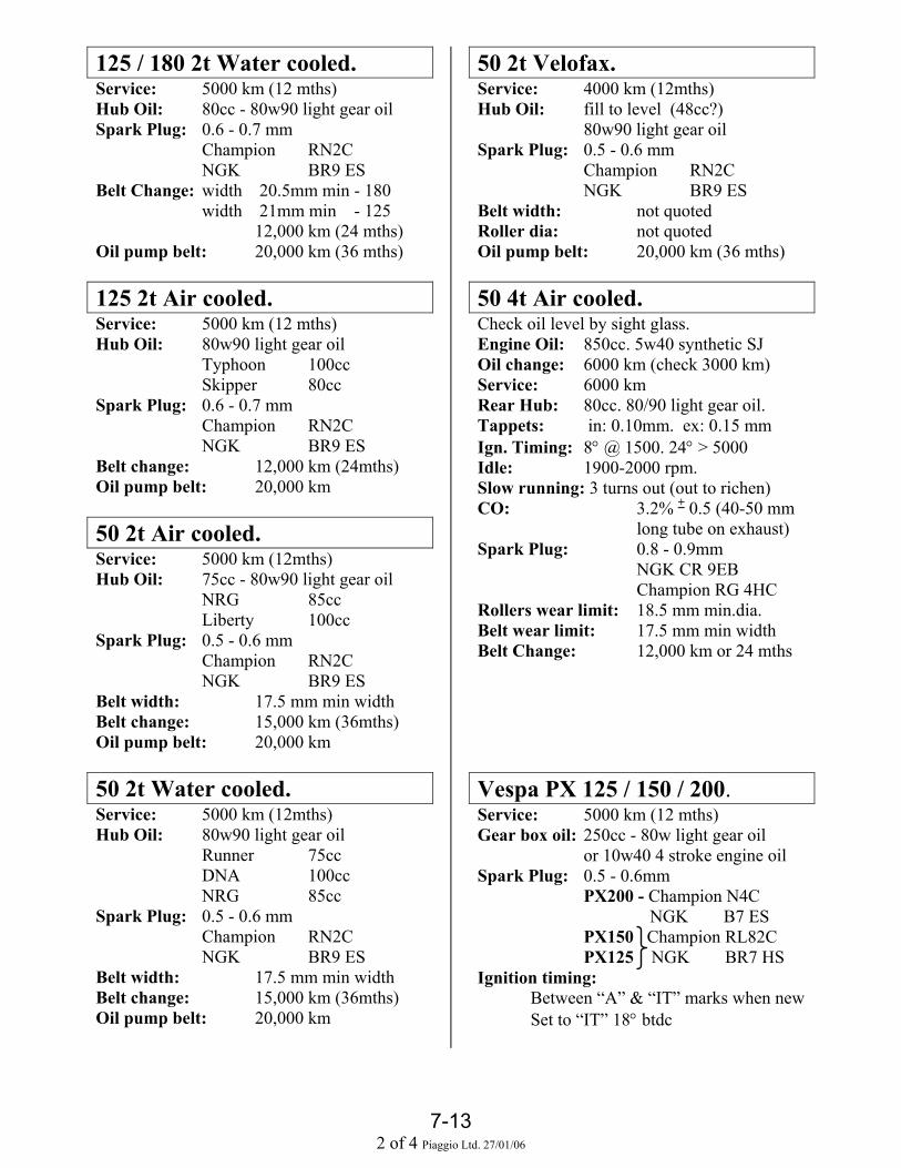
7-132 of 4 Piaggio Ltd. 27/01/06
125 / 180 2t Water cooled.Service: 5000 km (12 mths)Hub Oil: 80cc - 80w90 light gear oilSpark Plug: 0.6 - 0.7 mm
Champion RN2CNGK BR9 ES
Belt Change: width 20.5mm min - 180width 21mm min - 125
12,000 km (24 mths)Oil pump belt: 20,000 km (36 mths)
125 2t Air cooled.Service: 5000 km (12 mths)Hub Oil: 80w90 light gear oil
Typhoon 100ccSkipper 80cc
Spark Plug: 0.6 - 0.7 mmChampion RN2CNGK BR9 ES
Belt change: 12,000 km (24mths)Oil pump belt: 20,000 km
50 2t Air cooled.Service: 5000 km (12mths)Hub Oil: 75cc - 80w90 light gear oil
NRG 85ccLiberty 100cc
Spark Plug: 0.5 - 0.6 mmChampion RN2CNGK BR9 ES
Belt width: 17.5 mm min widthBelt change: 15,000 km (36mths)Oil pump belt: 20,000 km
50 2t Water cooled.Service: 5000 km (12mths)Hub Oil: 80w90 light gear oil
Runner 75ccDNA 100ccNRG 85cc
Spark Plug: 0.5 - 0.6 mmChampion RN2CNGK BR9 ES
Belt width: 17.5 mm min widthBelt change: 15,000 km (36mths)Oil pump belt: 20,000 km
50 2t Velofax.Service: 4000 km (12mths)Hub Oil: fill to level (48cc?)
80w90 light gear oilSpark Plug: 0.5 - 0.6 mm
Champion RN2CNGK BR9 ES
Belt width: not quotedRoller dia: not quotedOil pump belt: 20,000 km (36 mths)
50 4t Air cooled.Check oil level by sight glass.Engine Oil: 850cc. 5w40 synthetic SJOil change: 6000 km (check 3000 km)Service: 6000 kmRear Hub: 80cc. 80/90 light gear oil.Tappets: in: 0.10mm. ex: 0.15 mmIgn. Timing: 8° @ 1500. 24° > 5000Idle: 1900-2000 rpm.Slow running: 3 turns out (out to richen)CO: 3.2% + 0.5 (40-50 mm
long tube on exhaust)Spark Plug: 0.8 - 0.9mm
NGK CR 9EB Champion RG 4HC
Rollers wear limit: 18.5 mm min.dia.Belt wear limit: 17.5 mm min widthBelt Change: 12,000 km or 24 mths
Vespa PX 125 / 150 / 200.Service: 5000 km (12 mths)Gear box oil: 250cc - 80w light gear oil
or 10w40 4 stroke engine oilSpark Plug: 0.5 - 0.6mm
PX200 - Champion N4C NGK B7 ES
PX150 Champion RL82CPX125 NGK BR7 HS
Ignition timing:Between “A” & “IT” marks when newSet to “IT” 18° btdc

7-133 of 4 Piaggio Ltd. 27/01/06
125 4t Coguar. Honda XL125 engineCheck oil level with dipstick screwed OUT.Engine Oil: 1.2 ltr. 20w50 synthetic SGOil change: 3000 kmService: 6000 kmTappets: in:0.10 mm. ex: 0.10 mmIgn. Timing: 15° @ 1400. 32° @ 3450Idle: 1400 rpm.Slow running: 2 turns out (out to richen)CO: 5% + 0.5%Spark Plug: 0.8 - 0.9 mm
NGK DPR8 EA9Chain size:
500 4t MasterCheck oil level with dipstick screwed INEngine Oil: 1.7 ltr 5w40 synthetic SJOil change: 6000 km (check @ 3000 km)Service: 6000 km (12mths)Rear Hub: 250cc 80/90 light gear oil.Coolant: 1.8 ltr. 50 / 50 mixTappets: in: 0.15mm. ex: 0.15 mmIdle: 1450 rpm. + 50 rpm.CO: 1.25% + 0.25%CO2: 14.5% + 1%Spark Plug: 0.7 - 0.8mm
Champion RG6YCNGK CR7 EKB
Rollers wear limit: 24.5 mm min.dia.Belt wear limit: 25 mm width.Belt Change: 12,000 km or 24 mth.Air Filter Change: 18,000 km or 36 mth.Fuel Filter Change: 48,000 km
100 2t. Diesis. Derbi engineService: 5000 km (12 mths)Hub Oil: 110cc - 80w90 light gear oilSpark Plug: 0.6 - 0.7 mm
Champion RN2CNGK BR9 ES
Belt change: min width = 16mm5000 km (12 mths)Then every 10,000 km
50 2t H@K, GSM. Gilera engineService: 5000 km (12 mths)Gearbox Oil: 650cc - 10w40 4t engine oilSpark Plug: 0.5 - 0.6 mm
Champion RN2CNGK BR9 ES
Chain size: 415 x 124 links
50 2t RCR. Derbi engineService: 5000 km (12 mths)Gearbox Oil: 500cc - 10w40 4t engine oilSpark Plug: 0.5 - 0.6 mm
Champion RN2CNGK BR9 ES
Chain size: x 130 links
50 2t PUREJET. Direct injectionService: 5000 km (12mths)Hub Oil: 75cc - 80w90 light gear oil2T Oil: Fully Synthetic API TC++Spark Plug: 0.5 - 0.6 mm
Champion RG6 YCANGK ?
Belt width: 17.5 mm min widthBelt change: 15,000 km (36mths)Rollers: 18.5 mm min.dia.Fuel Filter: 10,000 km (24 mths)Mixer belt: 20,000 km

7-134 of 4 Piaggio Ltd. 27/01/06
250 4T QUASAR (carburettor)Check oil level with dipstick screwed INEngine Oil: 1.3 ltr 5w40 synthetic SJOil change: 10000 kmService: 10000 km (12mths)Rear Hub: 150cc 80/90 light gear oil (X9)Coolant: 1.2 ltr. 50 / 50 mixTappets: in: 0.10mm. ex: 0.15 mmIdle: 1650 rpm. + 50 rpm.CO: 3.8 + 0.7 @1650 rpm
(with SAS valve closed)Spark Plug: 0.7 - 0.8 mm
Champion RG4 HCNGK CR8 EB
Rollers wear limit: 20 mm min.dia.Belt wear limit: 19.5 mm width.Belt Change: 12,000 km or 24 mth.Air Filter: Clean at service
250 4T QUASAR (injection)Check oil level with dipstick screwed INEngine Oil: 1.3 ltr 5w40 synthetic SJOil change: 10,000 km (check @ 5000 km)Service: 10,000 kmRear Hub: 250cc 75/85 light gear oil GL4Coolant: 2.1 ltr. 50 / 50 mixTappets: in: 0.10mm. ex: 0.15 mmIdle: 1650 rpm. + 50 rpm.CO: N/ASpark Plug: 0.7 - 0.8 mm
Champion RG4 PHPNGK ?
Rollers wear limit: 20 mm min.dia.Belt wear limit: 19.5 mm min width.Belt Change: 15,000 km.Air Filter clean: 10,000 km
If there is ever any doubt about service intervals for a vehicle, always use the intervals shown inthe owners handbook.
Piaggio recommend fully synthetic oil for all engine applications. Older engines used variator rollers that needed greasing. Later greaseless rollers can be fitted to
early variators. If greased rollers are used lubricate sparingly at every service (except first): Useonly “Jota” grease p.n. 494643
Piaggio have never offered any tuning parts for any vehicles and we will never recommendtuning or de-restricting a vehicle for any reason.
All 50cc vehicles are only available as “mopeds” restricted to 45 kmh (28mph). All current 125cc vehicles are “Learner Legal” producing less than 15 hp (11kw). They are not
restricted. If they are tuned they will not be learner legal and warranty will be affected.

10Piaggio Ltd. 04/11/02
KEYS.All Leader engined vehicles with immobilisers
Notes: Only the Service key should be used day to day. The Master key should be kept
safely at home. Use the Service key for testing and fault finding. Only use the Master key for
programming. It is not possible to programme a replacement master key to a previously
programmed immobiliser. It is possible to programme new Service keys only if you have the original Master
key. Original Service keys with a chip fitted can be recognised by this symbol
etched into the metal near the top.
If new locks are fitted: Lock set will be supplied with one Master and one Service key. If you do not have any original keys then you must also change the CDI /
Immobliser unit. If you have the original Master key:
Use a screwdriver to pries the Master key apart so the Chip can be removed.Remove the chip from the new key and replace it with the original. Now theimmobiliser will not know that anything has changed.Now the system is working and you can programme the new Service keys.
Programming new Service keys:Programming is easy but be aware that precise timing can be important.
1.Master key in and turn on for TWO seconds 2. Service key in and turn on for TWO seconds 3. If you have a second Service key : In and turn on for TWO seconds 4. Master key in and turn on for TWO seconds You have up to ten seconds to change keys over. If you are adding an extra Service key you must re-programme all the Service
keys together, you can not just add a key. The system can remember up to seven keys at a time. If you programme an
eighth key then the first one will be forgotten.
Obtaining spare keys from an automotive lock smith:The system we use is also used by a lot of cars. Most automotive locksmiths will beable to supply spare Service keys. They can not supply new Master keys.
Give the locksmith the Master or Service key. They should have a suitable blank to cut. They will scan the key to identify the chip type fitted. They fit the appropriate chip to the new key. This chip will be a clone of the original so, programming will not be necessary.
Keys Galore – London – 020 7586 9741Express Keys – Kent – 01689 850008
First Access – Herts - 0115 967 6466Auto Keys – London – 020 7586 9741

Schematic wiring diagrams
Lights section
1 12v - 55w LOW BEAM BULB 12 7.5 AMP FUSE2 12v - 55w HIGH BEAM BULB 13 15 AMP FUSE3 LOW BEAM RELAY 14 7.5 AMP FUSE4 HIGH BEAM RELAY 15 7.5 AMP FUSE5 DIGITAL INSTRUMENTS 16 30 AMP FUSE6 LIGHTS SWITCH 17 12V - 14 Ah BATTERY
18 HELMET COMPARTMENT LIGHT SWITCH7 2x12V-5W FRONT PARKING LIGHT BULB2X12V-5W REAR PARKING LIGHT BULB1X12V-5W NUMBER PLATE LIGHT BULB 19 12V - 5W HELMET COMPARTMENT BULB
8 IGNITION SWITCH 20 12V - 180 AMP SOCKET9 MAIN POWER RELAY 21 15 AMP FUSE
10 3 PHASE AC GENERATOR 22 LIGHTS HIGH / LOW SELECTOR SWITCH11 RECTIFIER / REGULATOR 23 2A DIODE
4-7A

Schematic wiring diagrams
Ignition section
1 IMMOBILISER DECODER 11 IMMOBILISER AERIAL2 IGNITION SWITCH 12 ENGINE STOP RELAY3 RECTIFIER / REGULATOR 13 MAIN RELAY4 375w THREE PHASE GENERATOR 14 12v - 14 ah BATTERY5 ELECTRONIC CONTROL UNIT 15 30 amp MAIN FUSE6 HT COIL 16 ENGINE STOP SWITCH7 SPARK PLUG 17 10 amp FUSE8 DIGITAL INSTRUMENT PANEL 18 RELAY FOR ECU9 5 amp FUSE 19 SIDE STAND SWITCH
10 3 amp FUSE 20 DIODE
4-6A

M
RED
~ ~ ~ + +
YELLOW
YELLOW
1
RECTIFIER / REGULATOR
DIODE
MAIN POWERRELAY
RED
Lt. BLUE
GREY / BLACK
RED / BLACK
RED
WHITE
WHITE
WHITE / BLACK
RED / YELLOW
VIOLET
VIOLET
RED
RED
70 amp
YELLOW
11 YELLOW
STANDOPERATINGBUTTON
STAND LIMITSWITCHES
ORANGE
GREEN
GREY
16 GREY
4 GREY / BLACK
12 Lt. BLUE
1 VIOLET
15 GREEN
14 ORANGE
8 BLACK
DIGITALINSTRUMENTS
YELLOW
YELLOW
VIOLET
ORANGE / BLUE
GREY / RED
WH
ITE
BLUE
BLUE
ORANGE / BLUE
RELAY CONTROLUNIT
IGNITIONSWITCH
STANDACTUATOR
WHEELREVOLUTION
SENSOR
8685
30 87
BATTERY12v 14ah
RED / BLACK
STANDACTUATOR RELAYS
8685
30 87 BLUE
GREY
7.5 ampIn batterycompartment
30 ampIn BatteryCompartment
Under seat
Behind Fuel Tank
DOWN
UP
RUN
STOP
FRONTSTOP
REARSTOP
STARTERBUTTON
DIO
DE
ENGINESTOP
STARTERRELAY
SIDE STANDSWITCH
30/01/2006Piaggio Ltd.
X9 500 Stand Circuit
YELLOW / GREEN
RUN
OFF
There are two DIODES situated under the front cover above the headlight unit. They are together in black heat shrink tubingThere is a single DIODE in the grey wire.
ORANGE ORANGE / WHITE
OR
AN
GE
/BLU
E
YELL
OW
/ G
REE
N
BLUE / GREY
GREEN / BLACK
WHITE
RED
86 85
30 87
DIGITALINSTRUMENTPANEL
SIDESTANDWARNINGLIGHT
GR
EEN
/ B
LAC
K
CENTRESTAND
WARNINGLIGHT
BLACK
STAND CONTROL UNIT
161511 12 13 141091 2 3 4 5 6 7 8
Stand Control UnitPin Layout
In BatteryCompartment
? amp
RED
DIO
DE
8 - 3

30/01/2006Piaggio Ltd
Nexus 500 Instrument connection
You may find an incorrect wiring diagram, with wiring that does not match the vehicle.This diagram should match the vehicle.
Oil Pressure.Live feed to switch. Switch shorts to earth to light the bulb.Fuel Gauge.Live feed to unit in tank. The tank unit shorts it to earth via a variable resistor.If the gauge is not working.Un-plug the instruments put a meter between white / green and black.Low resistance = full tank. High resistance = empty tank.This has checked the wiring and tank unit.
8 - 4
16. Black. Earth.
17. Brown / White. Injector LED.
18. Blue. Turn switch right.
19. Pink / Black. Turn switch left.
20. Brown / Black. Hazard lights switch
+ to fuel gauge. White / Green. 15
Remote mode push button. Grey. 14
12v + switched live. Yellow / Red. 13
Immobiliser LED. Grey / Yellow. 12
12v + permanent live. Red / Black. 11
6. Orange. Coolant temperature sensor.
7. Lt Blue / Black. Coolant temp. earth.
8. Pink / White. Oil pressure switch +.
9. White / Blue. Right turn signal.
10. Pink. Left indicators
RPM signal (to ECU pin 3). Green 5.
Wheel sensor earth. Grey / Black 3.
Wheel speed sensor +. Red 1.
Lighting +. Yellow / Black 4.
Wheel speed sensor signal. Lt Blue 2.
INSTRUMENT PANELMULTI PIN CONNECTOR
Looking into theconnector on theback of the panel
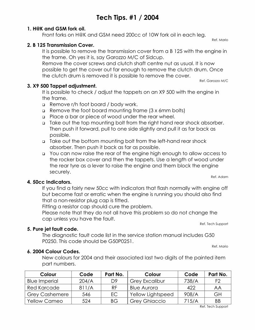
Tech Tips. #1 / 20041. H@K and GSM fork oil.
Front forks on H@K and GSM need 200cc of 10W fork oil in each leg.Ref. Mario
2. B 125 Transmission Cover.It is possible to remove the transmission cover from a B 125 with the engine inthe frame. Oh yes it is, say Garozzo M/C of Sidcup.Remove the cover screws and clutch shaft centre nut as usual. It is nowpossible to get the cover out far enough to remove the clutch drum. Oncethe clutch drum is removed it is possible to remove the cover.
Ref. Garozzo M/C
3. X9 500 Tappet adjustment.It is possible to check / adjust the tappets on an X9 500 with the engine inthe frame.
Remove r/h foot board / body work. Remove the foot board mounting frame (3 x 6mm bolts) Place a bar or piece of wood under the rear wheel. Take out the top mounting bolt from the right hand rear shock absorber.
Then push it forward, pull to one side slightly and pull it as far back aspossible.
Take out the bottom mounting bolt from the left-hand rear shockabsorber. Then push it back as far as possible.
You can now raise the rear of the engine high enough to allow access tothe rocker box cover and then the tappets. Use a length of wood underthe rear tyre as a lever to raise the engine and them block the enginesecurely.
Ref. Adam
4. 50cc Indicators.If you find a fairly new 50cc with indicators that flash normally with engine offbut become fast or erratic when the engine is running you should also findthat a non-resistor plug cap is fitted.Fitting a resistor cap should cure the problem.Please note that they do not all have this problem so do not change thecap unless you have the fault.
Ref. Tech Support
5. Pure jet fault code.The diagnostic fault code list in the service station manual includes G50P0250. This code should be G50P0251.
Ref. Mario
6. 2004 Colour Codes.New colours for 2004 and their associated last two digits of the painted itempart numbers.
Colour Code Part No. Colour Code Part No.Blue Imperial 204/A D9 Grey Excalibur 738/A F2Red Karcade 811/A RF Blue Aurora 422 AAGrey Cashemere 546 EC Yellow Lightspeed 908/A GHYellow Cameo 524 BG Grey Ghiaccio 715/A BB
Ref. Tech Support

Tech Tips. #2 / 20041. 125 leader engine. Poor pick up.
If you find that a scooter with a 125 Leader engine is reluctant to acceleratefrom stand still particularly when it has not warmed up fully.Check the tappets, they are probably slightly tight.Tappets should be inlet: 0.10mm. exhaust: 0.15mm.
Ref. Practical experience
2. X9 250 Evolution. Belt change.Please note that the drive belt should be changed at 18000km and not12000km as stated in the Service Schedule. Also the Secondary Air Systemshould be cleaned at 18000km.
Ref: NT12/03
3. DNA 125 / 180. Checking the Tappets.It is possible to check the tappets without spending a lot of time removing theengine.
You will be removing one of the engine mounting bolts so first you must find asuitable support to go under the bike in front of the engine (something like a milkcrate).
With the bike supported and the centre stand down remove the lower rearshock absorber bolt.
Remove the engine mounting bolt that is accessible. Only one of them can beremoved.
Carefully pull the engine backward and twist it slightly as you go. Watch thewires and pipes to make sure nothing is getting caught. The first pipe that willpull tight is one of the small black rubber cooling pipes.
You will be able to pull and turn the engine far enough to give good access tothe rock box bolts. Once the bolts are out it is easy to remove the cover andcheck the tappets.
Inlet:- 0.10 mm. Exhaust:- 0.15 mm.Practical experience.
4. Runner Purejet. Cutting out / loosing power.We have had a report from BMG Scooters that if the rear suspension of a RunnerPurejet is fully compressed it is possible for the Throttle Position Sensor plug to hitthe bottom of the helmet compartment. The plug does not come out but if theconnection is lost the engine will revert to idle speed and the throttle will notrespond. Please let us know if you have experienced this problem.
BMG.
5. Purejet. Using cheap 2 stroke oil.The owner’s handbook and Service Station Manual say that fully synthetic oilmust be used.If cheap oil is used more carbon is produced in the combustion chamber.Specks of carbon on the head of the injector valve and the carbon on thecylinder head can disrupt the dispersal of fuel enough to make the engine runvery badly. Also cheap oil will not give such good lubrication.These engines have proved to be very reliable when they are used correctly butremember that they are running on a very weak fuel mixture and very little oil tomake them clean burning and incredibly economic.Please take time to explain the importance of using fully synthetic oil to yourcustomers.
Practical experience.

Tech Tips. #3 / 20041. Leader drive belts.
Please note the correct service periods for drive belts on ALL Leader enginedvehicles.6000 km or 12 months. (2nd) service. Check the belt.12000 km or 24 months. (3rd) service. Change the belt.Then continue the cycle, i.e. 18000 - check, 24000 - change etc.When checking the belt, look for any signs of damage or fraying. Alsomeasure the width at the widest part as explained in the service stationmanual.Minimum width for 180 & 200 - 19.5 mmMinimum width for all 125 ------ 21.5 mm
2. Leader crankshaft / cases dimensions.Be aware that the current Leader crankshaft is different to earlier versions.Original crankshafts had a thrust washer on the out side of both crank webs.The current version has these washers built in.If you fit a new crank to old cases all you need to do is discard the washers.The internal width of the cases has never changed and the overall crankwidth will be the same.
3. Check Tappets. Particularly 125 Leader engine.If you have a four stroke that is reluctant to pull away until it is fully hot. Oneof your first checks should be the tappet clearances. Tight tappets will causethis problem.All Leader engines: 0.10 mm inlet. 0.15 mm exhaustAll Master engines : 0.15 mm inlet. 0.15 mm exhaustAll Quasar engines: 0.10 mm inlet. 0.15 mm exhaustPre Leader : 0.15 mm inlet. 0.15 mm exhaust50 cc 4 stroke : 0.10 mm inlet. 0.15 mm exhaust
4. X9 125 Digital instrument panel.Please note that the digital instrument panel 582142 is not interchangeablewith 584462.582142 has been re-introduced and should be used for non Evo X9 125.584462 should be used for the X9 125 evo.
Set with engineCOLD

Tech Tips # 4. September 20051. Always Change Variator Nuts.
The nut retaining the variator should always be changed if removed!The service station manuals advise changing them and for a very good reason.The nut is tightened to a high a high torque and subjected to big changes of temperature andhigh forces so it will deteriorate.You should remove the variator at service to check the condition of the rollers so I would advisekeeping a stock of nuts readily available in the workshop so there is no excuse for not fitting anew one!If the variator comes loose you are unlikely to get the repair authorised under warranty!And if the variator comes loose it will damage the crankshaft so it is a big job.
2. Grease Rear Wheel Spindles.Several models now have the rear wheel spindle supported on both sides of the wheel.It is worth removing the out rigger on the right side to grease the shaft where it passes throughthe bearing this will prevent it seizing in the bearing. Could can save you a lot of grief latter.
3. GTS coolant bleed nipple torque.The coolant bleed nipple on the GTS 250 engine will leak if over tightened. Once it startsleaking (because the casing has been distorted) you can not stop it.Torque it to the recommended 3Nm and no more! 3Nm is not much, if you do not have a torquewrench that can measure this you should tighten it not much more than finger tight.
4. Immobiliser looses it's program.Normally it is not possible for an immobiliser to loose it's programming but if you have a vehiclethat was running but now is showing a non programmed unit the cause could be extremeelectrical interference caused by a faulty plug cap or HT lead.Fit a new resistor plug cap (at least 5000 ohms) and plug lead before trying to reprogram theunit.
5. De-restricting 50'sAs you should know, Piaggio do not recommend de-restricting a 50 for any reason but weknow that they do get de-restricted and if you are going to do it we would sooner that you did itcorrectly to avoid any problems.If you do de-restrict please be aware of the legal implications and make your customer aware!
Normal de-restriction on current twist and go 50's is:Remove the spacer from the variator (don't forget to use a new nut, see above)Remove the resonator pipe (or pipes) from the exhaust pipe.Fit a larger main jet, about + 4 sizes.
In addition, it is worth fitting lighter rollers and blanking off the secondary air system.The roller weight has no affect on top speed but initial acceleration will not be very good withthe heavier rollers because it will get into high gear too quickly.
Original rollers on most current 50's are 6.4 gr. CM1102025.Replace these with 5,3 gr (orange) rollers CM11020035.
The secondary air system has nothing to do with performance but the reed valve may fail onthe higher power engine because the pulses it is subjected too are much greater, blank it off toimprove long term reliability.
We are aware that the NRG Power DT (air cooled) does not go much faster when de-restricted.We don't know why at the moment. Italy is investigating.
David ChampionTechnical Services

Tech Tips #5Walbro CV carburettors on four stroke engines.The carburettor fitted to many of Piaggio's four stroke engines is made by Walbro. This has a blackplastic arm on the side that is moved by a cam on the throttle cable fitting. The arm operates theaccelerator pump that injects extra petrol as the throttle comes off idle to help the engine pick upcrisply.If the arm's pivot becomes corroded the arm may stick and then the pump will not operate.Lack of the accelerator pump will show up as a reluctance to rev up quickly and a possibility ofcutting out if the throttle is opened rapidly.It is worth spraying this pivot with lubricant at ever service.
500cc engines. CO value.The CO values for 500cc Master engines should be taken when the engine has just reached it'snormal operating temperature.
If you take the reading at the tail pipe:0.6% - 0.7%Attach an 18 inch length of hose to the outlet and ensure that the probe is a far into the silencer aspossible to get an accurate reading.
If you take the reading from the exhaust pipe take off point:1.25% + 0.25%
Note. If the figure at the tail pipe is not about half that at the exhaust pipe this indicates a blockedcatalytic converter.
X9 500 Drive Belt.During the X9 500s life the transmission has been modified.Current engines have a longer drive belt because of changes to the transmission components.Make sure you fit the correct belt.827826 = older short belt832738 = new longer beltThe belt changed at about the time the Evo was launched but you will find pre Evo vehicles withthe long belt.Note. It is possible to fit a long belt to a short belt engine but if you do, it will ride further up thepulleys and will rub on the casing, eventually with catastrophic results!
50cc 4 Stroke.If you find a 50cc 4 stroke engine that feels slow at full throttle but is better at three quarter throttleit needs a larger main jet.Original jet is # 75#78 main jet part number: CM142103

SETTING THE CLOCK.
Any Piaggio / Vespa / Gilera scooter with a two button clock.
A
B
The clock should be displaying the hours and minutes with the two dots flashing.
Press button A once and the month and day will be displayed for about five seconds. Press and release button B once and the clock will alternately display the day and month and
then the hour and minute etc. Press and hold button B and you can set the month by pressing button A repeatedly until the
correct month is displayed. Release button B Press and hold button B again and you can set the day by pressing button A repeatedly until
the correct day is displayed. Release button B Press and hold button B again and you can set the hours by pressing button A repeatedly until
the correct hour is displayed. Release button B Press and hold button B again and you can set the minutes by pressing button A repeatedly
until the correct minutes are displayed. Release button B Press and release button B again and it will return the display to the normal hours and minutes. To return to the normal display at any time repeatedly press button B until the normal display is
shown.
3 : 29

LEADER / QUASAR Engine Special ToolCurrent LEADER engines have a modified cam chain cover. Early engines had a cast aluminiumcover retained by three screws.Current engines have a pressed metal cover, which is a push fit (QUASAR engines all have thissystem).The two seals are bonded to this cover.The cover should be changed every time it is removed.A special tool (020622Y) must be used when removing and fitting the cover.The later cover can be fitted to early engines without modification.If you fit a new variator to an early engine you will have to fit the new type cover.Below is the explanation of how to use the tool taken from the on line Service Station Manual.

INTERESTING FAULT FINDING.Here are a couple of recent cases that were solved quickly because the mechanic adopted alogical approach to fault finding.
FUEL GAUGE PROBLEMDetails: The fuel gauge is working but always shows a full tank when the ignition is on.
Unplug the tank unit and the gauge falls to empty (no circuit).Facts: Power goes to the clocks and then to the tank unit, which then shorts it to earth
via a variable resistor.You check the tank unit; high resistance (100 ohms) = low fuel level.Low resistance (3 ohms) = high fuel level. Unit is OK.You try a new tank unit anyway but there is no difference.You short the gauge to tank wire (normaly green / white) to earth, gauge goes to full.You have done the obvious checks, it all looks OK.So why is it not behaving correctly?
The clue is the resistance. The system needs high resistance to show low fuel level.If there is corrosion or water in a connector or in the instruments then there can be a leak to earth so the resistance is reduced and the gauge shows a higher fuel level.
The solution is to check block connectors, particularly the one on the back of theinstrument panel. If they are clean and dry then you need to change the instrument panel.
FOUR STROKE, RELUCTANT TO PICK UP.Details: The engine always starts and idles sweetly,
But it is reluctant to pick up particularly when cold.Once it does pick up it seems to run OK.
Facts: It is not a choke problem.The choke defaults to being on and the engine starts easily so the choke must be working. If you blocked the choke jet you would be unlikely to start a cold engine.It is not a spark problem because the engine starts easily and it does not cut out whenthe throttle is opened, it just does not want to accelerate.
Red Herring: It could be running weak.Probably not, because it will maintain high rpm once you can get it to pick up,Check for low fuel level in the carburettor just in case.Attach a length of clear plastic tube to the carburettor drain and turn it up the side of thecarburettor. Open the drain screw and observe the height of the fuel in the tube(it is the same as in the float bowl). It should be near the top of the float bowl, maybe4-5mm below the joint where the float bowl attaches to the carburettor body.
The solution: Check the tappets.You should find a tight tappet.
Correct tappet settings:50 4t:- 0.10 in, 0.15 ex.Leader:- 0.10 in, 0.15 ex.125 Pre Leader:- 0.15 in, 0.15 ex.Quasar:- 0.10 in, 0.15 ex.Master:- 0.15 in, 0.15 ex.Coguar 125:- 0.10 in, 0.10 ex.