pic programming module usb and traffic light system controller
DESCRIPTION
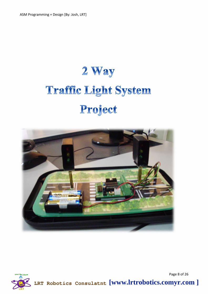
Special design traffic light control system using DIY PIC Programming Kit ... It's really cool!TRANSCRIPT

ASM Programming + Design [By: Josh, LRT]
Page 1 of 26
LRT Robotics Consulatnt [www.lrtrobotics.comyr.com ]

ASM Programming + Design [By: Josh, LRT]
Page 2 of 26
USB PORT Module Kit Construction
Components Needed:
1 PCB USBP V2.0
2 Wire Links U1, PROG 0.7mm tinned
4 10 Pin Socket with shroud PORT ABCD
1 LED D14 Yellow 5mm
1 16 Pin IC Socket U2
1 28 Pin IC Socket U1 Skinny DIP
6 1N5819 Diode D1, D2, D3, D4, D5, D6 Schottky Diodes
4 100n Capacitor C1, C2, C5, C8 Monolithic
2 220n Capacitor C6, C7 Monolithic
2 22pf Capacitor CA, CB Monolithic
1 10uf/35V Electrolytic C3 Capacitor
1 47uf/25V Electrolytic C4 Capacitor
1 6.000MHz Crystal Y1
1 390R Resistor R18 Metal Film 1%
1 1k5 Resistor R16 Metal Film 1%
1 5k6 Resistor R11 Metal Film 1%
1 10k Resistor R10 Metal Film 1%
1 68k Resistor R2 Metal Film 1%
1 120k Resistor R1 Metal Film 1%
1 4050 CMOS IC U2 16pin
1 PIC16C745-I/SP IC U1 28pin skinny
1 Preprogrammed USB PORT Module
1 USB-B Connector J1 PCB mount
1 Pack of 4 rubber feet Peel and Stick
LRT Robotics Consulatnt [www.lrtrobotics.comyr.com ]
ASM Programming + Design [By: Josh, LRT]
Page 3 of 26
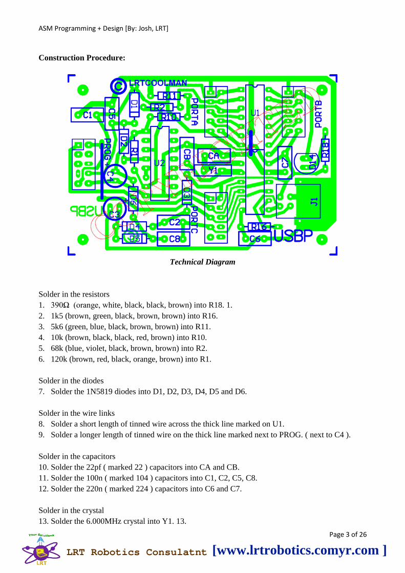
Construction Procedure:
Technical Diagram
Solder in the resistors
1. 390Ω (orange, white, black, black, brown) into R18. 1.
2. 1k5 (brown, green, black, brown, brown) into R16.
3. 5k6 (green, blue, black, brown, brown) into R11.
4. 10k (brown, black, black, red, brown) into R10.
5. 68k (blue, violet, black, brown, brown) into R2.
6. 120k (brown, red, black, orange, brown) into R1.
Solder in the diodes
7. Solder the 1N5819 diodes into D1, D2, D3, D4, D5 and D6.
Solder in the wire links
8. Solder a short length of tinned wire across the thick line marked on U1.
9. Solder a longer length of tinned wire on the thick line marked next to PROG. ( next to C4 ).
Solder in the capacitors
10. Solder the 22pf ( marked 22 ) capacitors into CA and CB.
11. Solder the 100n ( marked 104 ) capacitors into C1, C2, C5, C8.
12. Solder the 220n ( marked 224 ) capacitors into C6 and C7.
Solder in the crystal
13. Solder the 6.000MHz crystal into Y1. 13.
LRT Robotics Consulatnt [www.lrtrobotics.comyr.com ]
ASM Programming + Design [By: Josh, LRT]
Page 4 of 26
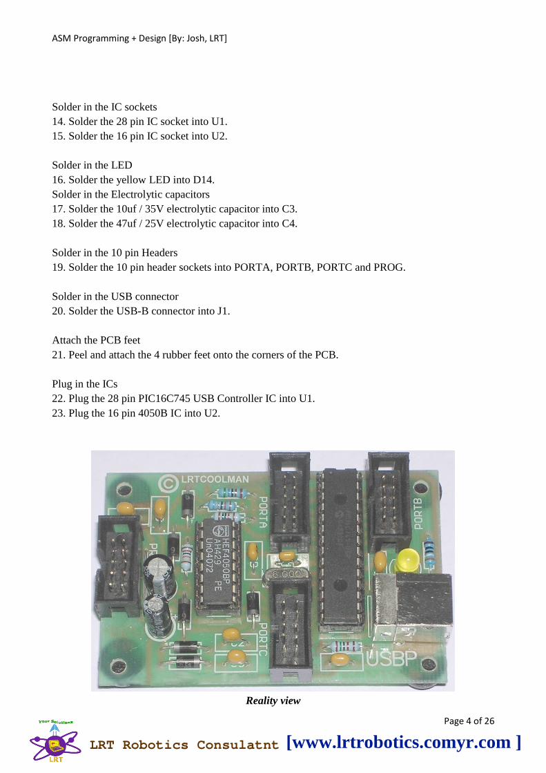
Solder in the IC sockets
14. Solder the 28 pin IC socket into U1.
15. Solder the 16 pin IC socket into U2.
Solder in the LED
16. Solder the yellow LED into D14.
Solder in the Electrolytic capacitors
17. Solder the 10uf / 35V electrolytic capacitor into C3.
18. Solder the 47uf / 25V electrolytic capacitor into C4.
Solder in the 10 pin Headers
19. Solder the 10 pin header sockets into PORTA, PORTB, PORTC and PROG.
Solder in the USB connector
20. Solder the USB-B connector into J1.
Attach the PCB feet
21. Peel and attach the 4 rubber feet onto the corners of the PCB.
Plug in the ICs
22. Plug the 28 pin PIC16C745 USB Controller IC into U1.
23. Plug the 16 pin 4050B IC into U2.
Reality view
LRT Robotics Consulatnt [www.lrtrobotics.comyr.com ]
ASM Programming + Design [By: Josh, LRT]
Page 5 of 26
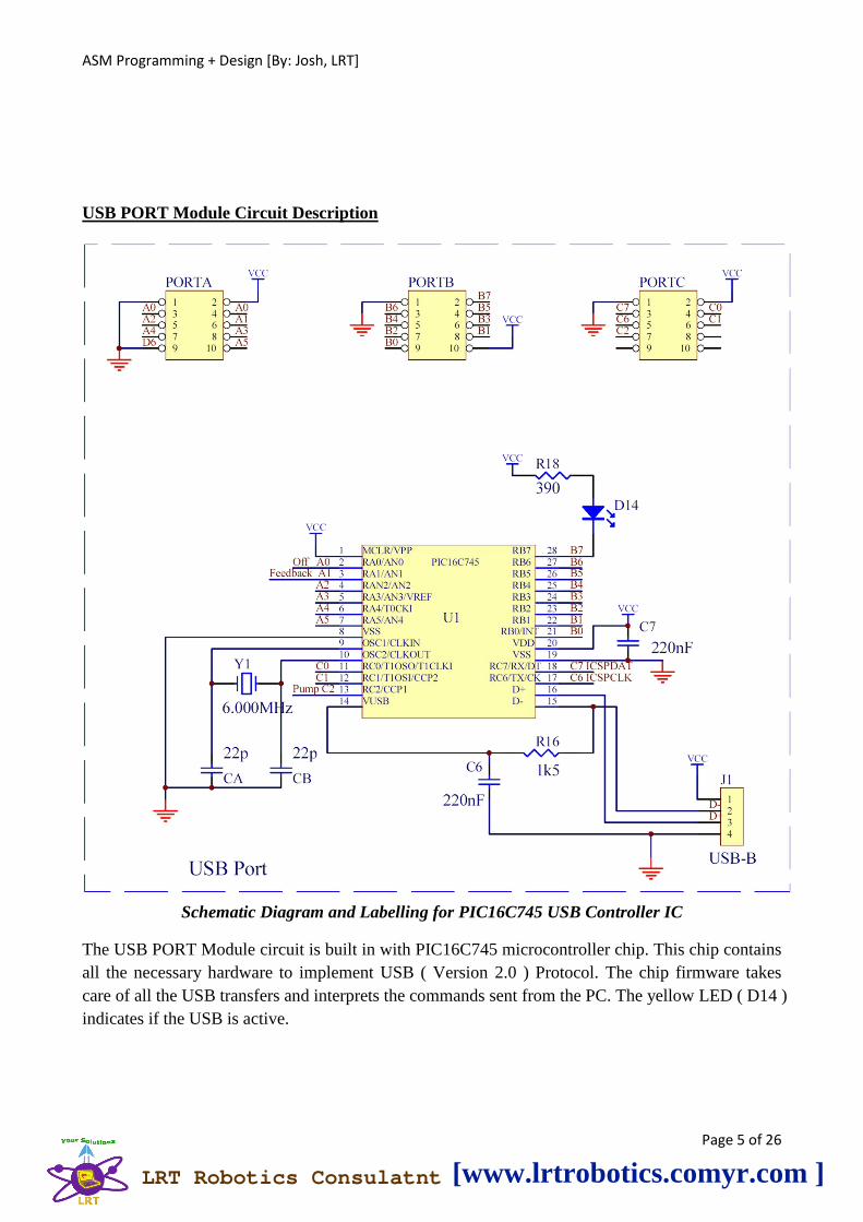
USB PORT Module Circuit Description
Schematic Diagram and Labelling for PIC16C745 USB Controller IC
The USB PORT Module circuit is built in with PIC16C745 microcontroller chip. This chip contains
all the necessary hardware to implement USB ( Version 2.0 ) Protocol. The chip firmware takes
care of all the USB transfers and interprets the commands sent from the PC. The yellow LED ( D14 )
indicates if the USB is active.
LRT Robotics Consulatnt [www.lrtrobotics.comyr.com ]

ASM Programming + Design [By: Josh, LRT]
Page 6 of 26
A diode / capacitor pump circuit ( D3, D4, D5 and D6 with C2, C8, C3 and C4 ) converts the 5V
p/p square wave pulses at “Pump” to +12V DC. This voltage runs the 4050 Buffer IC. A voltage
divider at “Feedback” controls the input of the 4050 from the PIC chip. Thus a +12V / +5V signal
can be switched to the „Program‟ pin of a PIC chip to place it in or out of program mode. The
ICSPDAT ( data ) and ICSPCLK ( clock ) signals transfer the data in and out ( for verification ) of
the Programmed PIC chip.
LRT Robotics Consulatnt [www.lrtrobotics.comyr.com ]
ASM Programming + Design [By: Josh, LRT]
Page 7 of 26
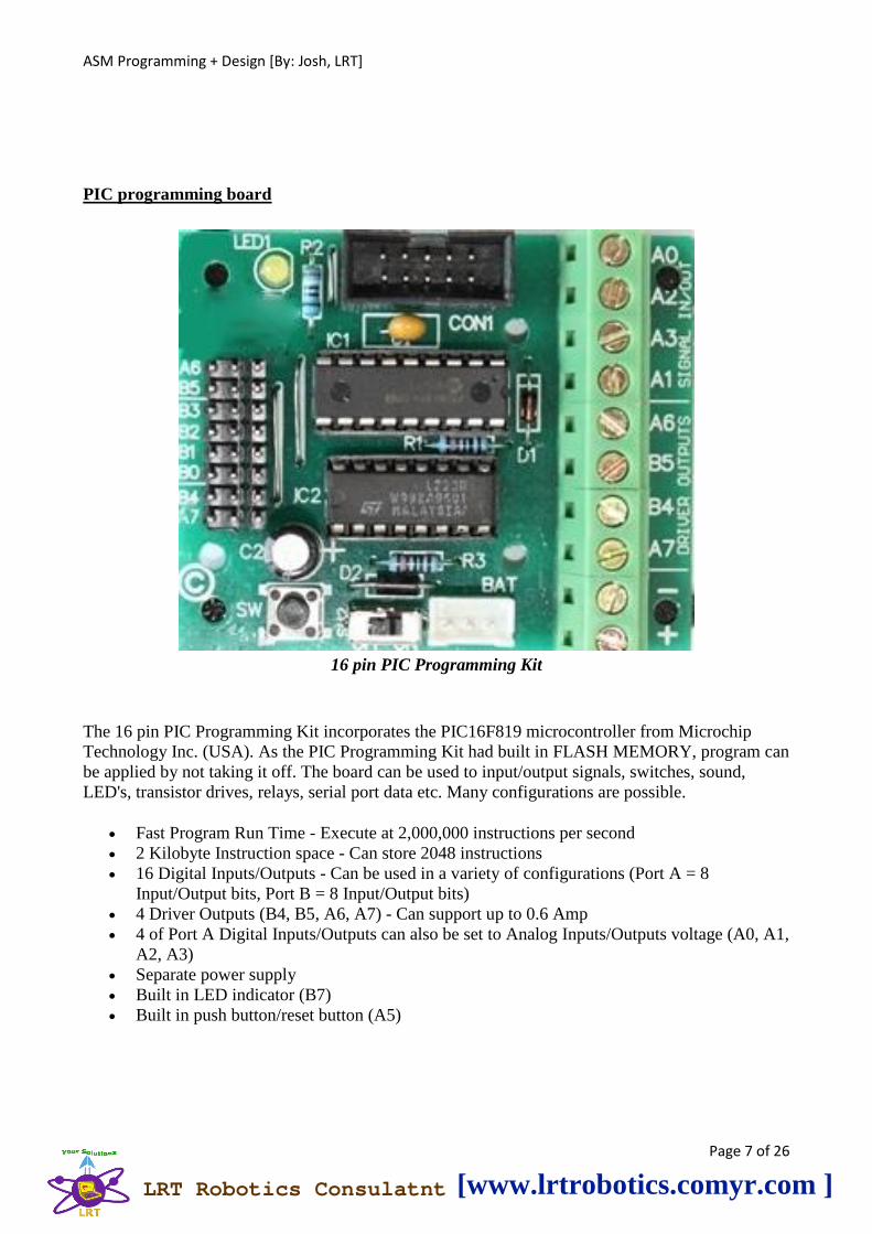
PIC programming board
16 pin PIC Programming Kit
The 16 pin PIC Programming Kit incorporates the PIC16F819 microcontroller from Microchip
Technology Inc. (USA). As the PIC Programming Kit had built in FLASH MEMORY, program can
be applied by not taking it off. The board can be used to input/output signals, switches, sound,
LED's, transistor drives, relays, serial port data etc. Many configurations are possible.
Fast Program Run Time - Execute at 2,000,000 instructions per second
2 Kilobyte Instruction space - Can store 2048 instructions
16 Digital Inputs/Outputs - Can be used in a variety of configurations (Port A = 8
Input/Output bits, Port B = 8 Input/Output bits)
4 Driver Outputs (B4, B5, A6, A7) - Can support up to 0.6 Amp
4 of Port A Digital Inputs/Outputs can also be set to Analog Inputs/Outputs voltage (A0, A1,
A2, A3)
Separate power supply
Built in LED indicator (B7)
Built in push button/reset button (A5)
LRT Robotics Consulatnt [www.lrtrobotics.comyr.com ]
ASM Programming + Design [By: Josh, LRT]
Page 8 of 26
LRT Robotics Consulatnt [www.lrtrobotics.comyr.com ]

ASM Programming + Design [By: Josh, LRT]
Page 9 of 26
SETUP Pin output
SETUP Diagram
Programming
Flat Assembler
LRT Robotics Consulatnt [www.lrtrobotics.comyr.com ]

ASM Programming + Design [By: Josh, LRT]
Page 10 of 26
Part List
Microcontroller
--------------------
1 × 16 pin PIC
1 × 20 Pin IC Socket
16V Capacitor
--------------------
2 × 100uF 16V Capacitor
6V Battery
--------------------
1 × 6V Battery
Capacitor
--------------------
1 × 100nF Capacitor
Piezo Buzzer
--------------------
1 × Piezo Buzzer
Power Connector
--------------------
1 × Power Connector
Red LED
--------------------
6 × Red LED
Resistor
--------------------
7 × 390 Resistor
2 × 10k Resistor
Schottky Diode IN5819
--------------------
1 × Schottky Diode IN5819
Switch
--------------------
1 × Switch
Transistor BC337
--------------------
1 × Transistor BC337
Voltage Regulator LM7805
--------------------
1 × Voltage Regulator LM7805
LRT Robotics Consulatnt [www.lrtrobotics.comyr.com ]

ASM Programming + Design [By: Josh, LRT]
Page 11 of 26
FULL ASM PROGRAMMING
;*********************************************
;*** ***
;*** Josh, LRT Traffic Light System Controller ***
;*** Copyright ©2013 Josh, LRT ***
;*** [email protected] ***
;*** ***
;*** ***
;*********************************************
LIST p=16F819,r=DEC ;Put assembler into PIC16F819 mode
#include <P16F819.INC>
__idlocs H'e1ab'
;***********Declare Bit Variables***********
#define T2_green PORTA, 7
#define T2_yellow PORTB, 4
#define T2_red PORTB, 5
#define Buzzer PORTA, 6
#define T1_green PORTA, 3
#define T1_yellow PORTA, 2
#define T1_red PORTA, 0
#define D4 PORTA, 3
#define D5 PORTA, 4
#define D6 PORTB, 6
#define D7_YellowLED PORTB, 7
#define EN PORTA, 2
#define RS PORTA, 1
#define RW PORTA, 0
#define Push_Button PORTA, 5
;***********Declare Variables***********
I equ 32
J equ 33
K equ 34
B2 equ 35
B1 equ 36
B0 equ 37
Hys equ 38
B3 equ 39
A3 equ 40
A0 equ 41
A1 equ 42
LRT Robotics Consulatnt [www.lrtrobotics.comyr.com ]

ASM Programming + Design [By: Josh, LRT]
Page 12 of 26
A2 equ 43
;***********Initialise Interrupt Subroutine***********
ORG 0x0000
goto InItSeTuP
ORG 0x0004
Interrupt
retfie ;
;***********Initialise Ports***********
InItSeTuP
__CONFIG B'11111100011000'
CLRF PORTA
CLRF PORTB
BSF STATUS,RP0
MOVLW B'10000000'
MOVWF OPTION_REG
BCF STATUS,RP0
XWZ1pmExy2
btfsc PORTA,5 ;If: PORTA Bit 5 OFF Then Skip
GoTo XWZ1pmExy2
BSF STATUS,RP0
MOVLW B'00110010'
MOVWF TRISA
MOVLW B'00000000'
MOVWF TRISB
MOVLW B'01110000' ;OSCCON
MOVWF OSCCON
BCF STATUS,RP0
call Setup
;******************Main Program******************
START
CALL OnOffPin20 ;
CALL OnOffPin21 ;
CALL TimeDelay9 ;
CALL OnOffPin23 ;
CALL OnOffPin22 ;
CALL TimeDelay10 ;
CALL OnOffPin24 ;
CALL OnOffPin25 ;
LRT Robotics Consulatnt [www.lrtrobotics.comyr.com ]

ASM Programming + Design [By: Josh, LRT]
Page 13 of 26
CALL TimeDelay11 ;
CALL OnOffPin33 ;
CALL OnOffPin26 ;
CALL TimeDelay12 ;
CALL OnOffPin27 ;
CALL OnOffPin28 ;
CALL TimeDelay13 ;
CALL OnOffPin29 ;
CALL OnOffPin30 ;
CALL OnOffPin31 ;
GOTO START ;
GOTO $
;******************Subroutines******************
Setup
CALL DigitalPort ;
MOVLW 100 ;
CALL DELAY ;
return ;
;-----------------------------------------------
LED_1Test
BSF T1_red ;
MOVLW 100 ;
CALL HundredthDelay ;
BCF T1_red ;
MOVLW 100 ;
CALL HundredthDelay ;
return ;
;-----------------------------------------------
LED_2Test
BSF T1_yellow ;
MOVLW 100 ;
CALL HundredthDelay ;
BCF T1_yellow ;
MOVLW 100 ;
CALL HundredthDelay ;
return ;
;-----------------------------------------------
LED_3Test
BSF T1_green ;
MOVLW 100 ;
CALL HundredthDelay ;
BCF T1_green ;
MOVLW 100 ;
CALL HundredthDelay ;
LRT Robotics Consulatnt [www.lrtrobotics.comyr.com ]

ASM Programming + Design [By: Josh, LRT]
Page 14 of 26
return ;
;-----------------------------------------------
LED_4Test
BSF T2_red ;
MOVLW 100 ;
CALL HundredthDelay ;
BCF T2_red ;
MOVLW 100 ;
CALL HundredthDelay ;
return ;
;-----------------------------------------------
LED_5Test
BSF T2_yellow ;
MOVLW 100 ;
CALL HundredthDelay ;
BCF T2_yellow ;
MOVLW 100 ;
CALL HundredthDelay ;
return ;
;-----------------------------------------------
LED_6Test
BSF T2_green ;
MOVLW 100 ;
CALL HundredthDelay ;
BCF T2_green ;
MOVLW 100 ;
CALL HundredthDelay ;
return ;
;-----------------------------------------------
Buzzer_1Test
BSF Buzzer ;
MOVLW 100 ;
CALL HundredthDelay ;
BCF Buzzer ;
MOVLW 100 ;
CALL HundredthDelay ;
return ;
;-----------------------------------------------
DigitalPort
BSF STATUS,RP0 ;
MOVLW 6 ;
MOVWF ADCON1 ;
BCF STATUS,RP0 ;
return ;
;-----------------------------------------------
LRT Robotics Consulatnt [www.lrtrobotics.comyr.com ]

ASM Programming + Design [By: Josh, LRT]
Page 15 of 26
DELAY
MOVWF J ;
Dloop ;
DECFSZ I,F ;
GOTO Dloop ;
DECFSZ J,F ;
GOTO Dloop ;
return ;
;-----------------------------------------------
HundredthDelay
MOVWF K ;
Loop100th ;
MOVLW 100 ;
MOVWF J ;
outerLoop ;
MOVLW 248 ;
MOVWF I ;
innerLoop ;
DECFSZ I,F ;
GOTO innerLoop ;
DECFSZ J,F ;
GOTO outerLoop ;
DECFSZ K,F ;
GOTO Loop100th ;
return ;
;-----------------------------------------------
OnOffPin
;MACRO_MODULE*
;TYP, 0
;MOD, 1
;IOS
;CAP, On Off Pin
;DSC, The 'ON OFF PIN module sets the pin in the 'OUTPUT PIN' box to either ON or OFF.
return ;
;-----------------------------------------------
OnOffPin0
BSF T1_red ;
CALL OnOffPin ;
return ;
;-----------------------------------------------
OnOffPin1
BSF T2_red ;
CALL OnOffPin ;
return ;
;-----------------------------------------------
LRT Robotics Consulatnt [www.lrtrobotics.comyr.com ]

ASM Programming + Design [By: Josh, LRT]
Page 16 of 26
TimeDelay
;MACRO_MODULE*
;TYP, 14
;MOD, 3
;USR, A0:00
;USR, A1:00
;USR, A2:00
;USR, A3:00
;CAP, Delay
;DSC, The TimeDelay module will pause the program for the amount of time specified in the
selected fields.
MOVLW 1
MOVWF B3 ; All pins on PORTA to digital I/O
MOVF A0, W
MOVWF A0 ; check for zero
btfsc STATUS,Z ;
GOTO Seconds ;
MinsLoop ;
CALL MinDelay ;
DECFSZ A0,F ;
GOTO MinsLoop ;
Seconds ;
MOVF A1, W
MOVWF A1 ; check for zero
btfsc STATUS,Z ;
GOTO HunsLoop ;
SecsLoop ;
CALL SecDelay ;
DECFSZ A1,F ;
GOTO SecsLoop ;
HunsLoop ;
MOVF A2, W
MOVWF A2 ; check for zero
btfsc STATUS,Z ;
GOTO TenKLoop ;
MOVF A2, W ;
CALL HunSecDelay ;
TenKLoop ;
MOVF A3, W
MOVWF A3 ; check for zero
btfsc STATUS,Z ;
return ;
CALL TenKDelay ;
return ;
;-----------------------------------------------
LRT Robotics Consulatnt [www.lrtrobotics.comyr.com ]

ASM Programming + Design [By: Josh, LRT]
Page 17 of 26
MinDelay
MOVLW 60
MOVWF Hys ;
MinLoop ;
CALL SecDelay ;
DECFSZ Hys,F ;
GOTO MinLoop ;
return ;
;-----------------------------------------------
SecDelay
MOVLW 100 ;
CALL HunSecDelay ;
return ;
;-----------------------------------------------
HunSecDelay
MOVWF B2 ;
TenThouLoop ;
;delays for a set number of centiseconds(100ths)
;W=number of 100ths to delay
MOVLW 20
MOVWF B1 ;
Loop100th1 ;
MOVLW 248 ;
MOVWF B0 ;
LoopNop ;
NOP ;
DECFSZ B0,F ;
GOTO LoopNop ;
DECFSZ B1,F ;
GOTO Loop100th1 ;
DECFSZ B2,F ;
GOTO TenThouLoop ;
return ;
;-----------------------------------------------
TenKDelay
Loop1 ;
DECF B3,F ;
btfsc STATUS,Z ;
GOTO offset ;
MOVLW 48
MOVWF B0 ;
Loop2 ;
NOP ;
DECFSZ B0,F ;
GOTO Loop2 ;
LRT Robotics Consulatnt [www.lrtrobotics.comyr.com ]

ASM Programming + Design [By: Josh, LRT]
Page 18 of 26
DECFSZ A3,F ;
GOTO Loop1 ;
return ;
offset ;
MOVLW 36
MOVWF B0 ;
GOTO Loop2 ;
return ;
;-----------------------------------------------
TimeDelay0
CLRF A0 ;
MOVLW 05
MOVWF A1 ;
CLRF A2 ;
CLRF A3 ;
CALL TimeDelay ;
return ;
;-----------------------------------------------
OnOffPin2
BSF T1_green ;
CALL OnOffPin ;
return ;
;-----------------------------------------------
OnOffPin3
BSF T2_green ;
CALL OnOffPin ;
return ;
;-----------------------------------------------
TimeDelay1
CLRF A0 ;
MOVLW 07
MOVWF A1 ;
CLRF A2 ;
CLRF A3 ;
CALL TimeDelay ;
return ;
;-----------------------------------------------
OnOffPin4
BSF T1_yellow ;
CALL OnOffPin ;
return ;
;-----------------------------------------------
OnOffPin5
BSF T2_yellow ;
CALL OnOffPin ;
LRT Robotics Consulatnt [www.lrtrobotics.comyr.com ]

ASM Programming + Design [By: Josh, LRT]
Page 19 of 26
return ;
;-----------------------------------------------
Add
;MACRO_MODULE*
;TYP, 3
;MOD, 3
;USR, A0:
;USR, B0:
;OUT, A0
;CAP, Addition
;DSC, The 'Add' module adds the value in the first box to the value in the second box and stores the
result as the name in the 'SAVE RESULT AS' box. A new or existing name can be used.
MOVF B0, W ;
CLRF A1 ;
ADDWF A0,F ;
btfsc STATUS,C ;
MOVLW 255
btfsc STATUS,C ;
MOVWF A0 ;
MOVF A0, W ;
return ;
;-----------------------------------------------
TimeDelay2
CLRF A0 ;
MOVLW 03
MOVWF A1 ;
CLRF A2 ;
CLRF A3 ;
CALL TimeDelay ;
return ;
;-----------------------------------------------
OnOffPin6
BCF T1_red ;
CALL OnOffPin ;
return ;
;-----------------------------------------------
OnOffPin7
BCF T2_red ;
CALL OnOffPin ;
return ;
;-----------------------------------------------
OnOffPin8
BCF T1_red ;
CALL OnOffPin ;
return ;
LRT Robotics Consulatnt [www.lrtrobotics.comyr.com ]
ASM Programming + Design [By: Josh, LRT]
Page 20 of 26
;-----------------------------------------------
OnOffPin9
BCF T2_red ;
CALL OnOffPin ;
return ;
;-----------------------------------------------
All_Red_5s
CALL OnOffPin0 ;
CALL OnOffPin1 ;
CALL TimeDelay0 ;
CALL OnOffPin8 ;
CALL OnOffPin9 ;
return ;
;-----------------------------------------------
OnOffPin10
BCF T1_green ;
CALL OnOffPin ;
return ;
;-----------------------------------------------
OnOffPin11
BCF T2_green ;
CALL OnOffPin ;
return ;
;-----------------------------------------------
All_Green_7s
CALL OnOffPin2 ;
CALL OnOffPin3 ;
CALL TimeDelay1 ;
CALL OnOffPin10 ;
CALL OnOffPin11 ;
return ;
;-----------------------------------------------
OnOffPin12
BCF T1_yellow ;
CALL OnOffPin ;
return ;
;-----------------------------------------------
OnOffPin13
BCF T2_yellow ;
CALL OnOffPin ;
return ;
;-----------------------------------------------
All_Yellow_3s
CALL OnOffPin4 ;
CALL OnOffPin5 ;
LRT Robotics Consulatnt [www.lrtrobotics.comyr.com ]

ASM Programming + Design [By: Josh, LRT]
Page 21 of 26
CALL TimeDelay2 ;
CALL OnOffPin12 ;
CALL OnOffPin13 ;
return ;
;-----------------------------------------------
OnOffPin14
BSF T1_green ;
CALL OnOffPin ;
return ;
;-----------------------------------------------
OnOffPin15
BSF T2_green ;
CALL OnOffPin ;
return ;
;-----------------------------------------------
TimeDelay3
CLRF A0 ;
MOVLW 07
MOVWF A1 ;
CLRF A2 ;
CLRF A3 ;
CALL TimeDelay ;
return ;
;-----------------------------------------------
TimeDelay4
CLRF A0 ;
CLRF A1 ;
MOVLW 30
MOVWF A2 ;
CLRF A3 ;
CALL TimeDelay ;
return ;
;-----------------------------------------------
OnOffPin16
BSF T1_green ;
CALL OnOffPin ;
return ;
;-----------------------------------------------
OnOffPin17
BSF T2_green ;
CALL OnOffPin ;
return ;
;-----------------------------------------------
TimeDelay5
CLRF A0 ;
LRT Robotics Consulatnt [www.lrtrobotics.comyr.com ]

ASM Programming + Design [By: Josh, LRT]
Page 22 of 26
CLRF A1 ;
MOVLW 30
MOVWF A2 ;
CLRF A3 ;
CALL TimeDelay ;
return ;
;-----------------------------------------------
OnOffPin18
BCF T2_green ;
CALL OnOffPin ;
return ;
;-----------------------------------------------
OnOffPin19
BCF T1_green ;
CALL OnOffPin ;
return ;
;-----------------------------------------------
TimeDelay6
CLRF A0 ;
CLRF A1 ;
MOVLW 30
MOVWF A2 ;
CLRF A3 ;
CALL TimeDelay ;
return ;
;-----------------------------------------------
All_Green_f1x
CALL OnOffPin16 ;
CALL OnOffPin17 ;
CALL TimeDelay5 ;
CALL OnOffPin19 ;
CALL OnOffPin18 ;
CALL TimeDelay6 ;
return ;
;-----------------------------------------------
All_Green_f3x
CALL TimeDelay7 ;
CALL All_Green_f1x ;
CALL All_Green_f1x ;
CALL All_Green_f1x ;
return ;
;-----------------------------------------------
TimeDelay7
CLRF A0 ;
CLRF A1 ;
LRT Robotics Consulatnt [www.lrtrobotics.comyr.com ]
ASM Programming + Design [By: Josh, LRT]
Page 23 of 26
MOVLW 30
MOVWF A2 ;
CLRF A3 ;
CALL TimeDelay ;
return ;
;-----------------------------------------------
OnOffPin20
BSF T1_red ;
CALL OnOffPin ;
return ;
;-----------------------------------------------
OnOffPin21
BSF T2_green ;
CALL OnOffPin ;
return ;
;-----------------------------------------------
TimeDelay8
CLRF A0 ;
MOVLW 11
MOVWF A1 ;
CLRF A2 ;
CLRF A3 ;
CALL TimeDelay ;
return ;
;-----------------------------------------------
TimeDelay9
CLRF A0 ;
MOVLW 07
MOVWF A1 ;
CLRF A2 ;
CLRF A3 ;
CALL TimeDelay ;
return ;
;-----------------------------------------------
OnOffPin22
BSF T2_yellow ;
CALL OnOffPin ;
return ;
;-----------------------------------------------
TimeDelay10
CLRF A0 ;
MOVLW 03
MOVWF A1 ;
CLRF A2 ;
CLRF A3 ;
LRT Robotics Consulatnt [www.lrtrobotics.comyr.com ]

ASM Programming + Design [By: Josh, LRT]
Page 24 of 26
CALL TimeDelay ;
return ;
;-----------------------------------------------
OnOffPin23
BCF T2_green ;
CALL OnOffPin ;
return ;
;-----------------------------------------------
OnOffPin24
BCF T2_yellow ;
CALL OnOffPin ;
return ;
;-----------------------------------------------
OnOffPin25
BSF T2_red ;
CALL OnOffPin ;
return ;
;-----------------------------------------------
TimeDelay11
CLRF A0 ;
MOVLW 01
MOVWF A1 ;
CLRF A2 ;
CLRF A3 ;
CALL TimeDelay ;
return ;
;-----------------------------------------------
OnOffPin26
BSF T1_green ;
CALL OnOffPin ;
return ;
;-----------------------------------------------
TimeDelay12
CLRF A0 ;
MOVLW 07
MOVWF A1 ;
CLRF A2 ;
CLRF A3 ;
CALL TimeDelay ;
return ;
;-----------------------------------------------
OnOffPin27
BCF T1_green ;
CALL OnOffPin ;
return ;
LRT Robotics Consulatnt [www.lrtrobotics.comyr.com ]

ASM Programming + Design [By: Josh, LRT]
Page 25 of 26
;-----------------------------------------------
OnOffPin28
BSF T1_yellow ;
CALL OnOffPin ;
return ;
;-----------------------------------------------
TimeDelay13
CLRF A0 ;
MOVLW 03
MOVWF A1 ;
CLRF A2 ;
CLRF A3 ;
CALL TimeDelay ;
return ;
;-----------------------------------------------
OnOffPin29
BCF T1_yellow ;
CALL OnOffPin ;
return ;
;-----------------------------------------------
OnOffPin30
BCF T2_red ;
CALL OnOffPin ;
return ;
;-----------------------------------------------
OnOffPin31
BSF T1_red ;
CALL OnOffPin ;
return ;
;-----------------------------------------------
OnOffPin32
BCF T1_red ;
CALL OnOffPin ;
return ;
;-----------------------------------------------
OnOffPin33
BCF T1_red ;
CALL OnOffPin ;
return ;
;-----------------------------------------------
END
LRT Robotics Consulatnt [www.lrtrobotics.comyr.com ]

ASM Programming + Design [By: Josh, LRT]
Page 26 of 26
It WORKS!
LRT Robotics Consulatnt [www.lrtrobotics.comyr.com ]