picturetel 4500vers-guide6.30
TRANSCRIPT

Concorde•4500
Administrator’s Guide

Copyright © 1998: PictureTel Corporation—Printed in U.S.A.PictureTel Corporation, 100 Minuteman Road, Andover, MA 01810www.picturetel.com
PictureTel is a registered trademark of PictureTel Corporation. The PictureTel logo, Concorde, GroupBoard, GroupShare, GroupView, LimeLight, LiveShare Plus, System 4000, M-8000, HVQ, SG3, SG4, Link-64E, IDEC, WorldCart, PowerMic, Look-At-Me-Button, LAMB, QuickPad, and IMX are trademarks of PictureTel Corporation.
ACCUNET, DATAPHONE, and Touch-Tone are registered trademarks of AT&T; MPDM is a trademark of AT&T.Velcro is a registered trademark of Velcro USA, Inc.DATAPATH is a trademark of Northern Telecom.
The information contained in this document is subject to change without notice. PictureTel assumes no responsibility for technical or editorial errors or omissions that may appear in this document or for the use of this material. Nor does PictureTel make any commitment to update the information contained in this document. This document contains proprietary information which is protected by copyright. All rights reserved. No part of this document may be photocopied or reproduced in any form without the prior written consent of PictureTel Corporation.
Edition: 800-0304-04/ACustomer order number: DOC-S4500-ADMN
Warning: Changes or modifications to this unit not expressly approved by the party responsible for compliance could void the user’s authority to operate the equipment.
This equipment has been tested and found to comply with the limits for a Class A digital device, pursuant to Part 15 of the FCC Rules. These limits are designed to provide reasonable protection against harmful interference when the equipment is operated in a commercial environment. This equipment generates, uses, and can radiate radio frequency energy and, if not installed, operated, and maintained in accordance with PictureTel Corporation guides and manuals, may cause harmful interference to radio communications. Operation of this equipment in a residential area is likely to cause harmful interference in which case the user will be required to correct the interference at his own expense.
Shielded cables must be used with this unit to ensure compliance with the Class A FCC limits.
Do you have any suggestions or comments on the documentation you received with Concorde•4500? If so, please send them by e-mail to [email protected].

Note: In this document, the term “monitor” is used to refer to the NTSC or PAL television (TV) broadcast receiver that is part of the Concorde•4500 system. These receivers are governed by different regulations than computer monitors.
Bescheinigung Des Herstellers/ImporteursHiermit wird bescheinigt, daß das Concorde•4500 in Übereinstimmung mit den Bestimmungen der Vfg 1046/1984 funkenstört ist.Der Deutschen Bundespost wurde das Inverkehrbringen dieses Geräts angezeigt und die Berechtigung zur Überprüfung der Serie auf Einhaltung der Bestimmungen eingeräumt. Dieses Gerät wurde sowohl einzeln als auch in einer Anlage, die dem normalen Anwendungsfall entspricht, auf die Einhaltung der Funkentstörbestimmungen geprüft. Es ist jedoch möglich, daß die Funkentstörbestimmungen unter ungünstigen Umständen bei anderen Gerätekombinationen nicht eingehalten werden. Für die Einhaltung der Funkentstörbestimmungen der gesamten Anlage, in der dieses Gerät betrieben wird, ist der Betreiber verantwortlich.
Notice to Users of Public DATAPHONE® Digital ServiceThe following instructions are provided to ensure that you comply with FCC Rules, Part 68.
1. All direct connections to DDS lines must be made through standard plugs and jacks furnished by the telephone company. No connections can be made to party lines or coin lines. Before connecting your unit, you must do the following:
a. Tell your local telephone company that you have an FCC registered device and that you wish to connect to the company’s line. Provide them with the 14-digit FCC registration number listed on the device’s label. They will also need to know the facility interface code and service code to connect the necessary service. For your unit, the facility interface code is 04DU5-56 for 56 kbps service. The service code is 6.0Y.
b. Inform the local telephone company of the jack arrangement you want to use, which is RJ-48S.
c. Connect the channel service unit (CSU) with the appropriate cable after the telephone company has installed the requested jack.
2. If the unit appears to be malfunctioning, it should be disconnected from the telephone line until you learn if your equipment or the telephone line is the source of the trouble. If your equipment needs repair, it should not be reconnected until it is repaired.
3. The CSU is designed to prevent harm to the DDS network. If the telephone company finds that the equipment exceeds tolerance parameters, the telephone company can temporarily disconnect service, although they will attempt to give you advance notice if possible.
4. Under FCC Rules, no customer is authorized to repair this equipment. This restriction applies regardless of whether the equipment is in or out of warranty.

5. If the telephone company alters their equipment or operations in a manner that will affect use of this device, they must give you advance warning so as to give you the opportunity for uninterrupted service. You will be advised of your right to file a complaint with the FCC.
6. In the event of equipment malfunction, all repairs should be performed by PictureTel Corporation or an authorized agent. It is the responsibility of the users requiring service to report the need for service to our company or to one of our authorized agents.
Note: It is illegal to export a Concorde•4500 system that contains the encryption option from the United States without approval from the United States Department of State. See your PictureTel sales representative for details.
Notice to Canadian UsersThis digital apparatus does not exceed the Class A limits for radio noise emissions from digital apparatus set out in the Radio Interference Regulations of the Canadian Department of Communications (DOC).
Le présent appareil numérique n’émet pas de bruits radioélectriques dépassant les limites applicables aux appareils numériques de la class A prescrites dans le Réglement sur le brouillage radioélectrique édicté par le ministère des Communications du Canada.
The Canadian Department of Communications label identifies certified equipment. This certification means that the equipment meets certain telecommunications network protective, operational, and safety requirements. The Department does not guarantee the equipment will operate to the user’s satisfaction. Before installing this equipment, users should ensure that it is permissible to be connected to the facilities of the local telecommunications company. The equipment must also be installed using an acceptable method of connection. In some cases, the company’s inside wiring associated with a single line individual service may be extended by means of a certified connector assembly (telephone extension cord). The customer should be aware that compliance with the above conditions may not prevent degradation of service in some situations. Repairs to certified equipment should be made by an authorized Canadian maintenance facility designated by the supplier. Any repairs or alterations made by the user to this equipment, or equipment malfunctions, may give the telecommunications company cause to request the user to disconnect the equipment. Users should ensure, for their own protection, that the electrical ground connections of the power utility, telephone lines, and internal metallic water pipe system, if present, are connected together. This precaution may be particularly important in rural areas.
DOC Load Number (LN) = 6
Caution: Users should not attempt to make such connections themselves, but should contact the appropriate electric inspection authority, or electrician, as appropriate.

FCC Part 68 Notice (U.S.)The Load Number (LN) assigned to each terminal device denotes the percentage of the total load to be connected to a telephone loop which is used by the device, to prevent overloading. The termination on a loop may consist of any combination of devices subject only to the requirement that the total of the Load Numbers of all the devices does not exceed 100.Ringer Equivalence Number (REN) = .6B
Connection To United Kingdom Telecommunications NetworkThe PictureTel Concorde•4500 is approved to connect to the following United Kingdom (UK) Public Telecommunications Operator (PTO) network services:
❑ Indirect connection to PTO-provided digital switched and point-to-point services through suitable approved branch systems.
This includes the following types of connections:
❑ Indirect connection to basic rate ISDN services (for example, British Telecom’s ISDN2 service) through approved terminal adaptors, multiplexers, or PABXs.
❑ Indirect connection to digital leased lines (for example, British Telecom’s Kilostream and Megastream services) through approved equipment, such as multiplexers or PABXs.
The Approval Number is: NS/3832/1/M/602676
The Concorde•4500 as approved above is comprised of the following elements:
❑ Electronics module
❑ Keypad
❑ Line-in microphones
❑ Microphones
❑ X.21 (V.11) connecting cables
All other equipment shipped as part of a Concorde•4500 (for example, cameras or monitors) is approved to connect indirectly to the UK PTO networks when connected through the Concorde•4500 electronics module under the terms of General Approval Number NS/G/1234/J/100003.
Warning: The Concorde•4500 must not be connected directly to any UK PTO provided services.


Contents
Chapter 1Introducing the Concorde¥4500
Wireless Keypad ............................................................................................................................. 1-3
QuickPad.......................................................................................................................................... 1-4
Monitors ........................................................................................................................................... 1-5
Electronics Module ......................................................................................................................... 1-6
Cameras............................................................................................................................................ 1-7
LimeLight......................................................................................................................................... 1-8
Microphones .................................................................................................................................... 1-9
WorldCart ...................................................................................................................................... 1-10
Look-At-Me-Button ...................................................................................................................... 1-11
Optional Equipment ..................................................................................................................... 1-12
Using the Concorde¥4500 Menu System .................................................................................. 1-13
Using the Setup Menu ........................................................................................................ 1-13
Navigating Through the Menus........................................................................................ 1-14
Using the Character Grid to Enter Information.............................................................. 1-14
Using Online Help ........................................................................................................................ 1-15
Supplying Information for the UserÕs Notebook ..................................................................... 1-16
vii

Chapter 2Connecting and Configuring Your Network
Attaching Digital Network Cables................................................................................................2-2
Internal Four-Wire Channel Service Unit (CSU)...............................................................2-2
V.35 Network Interface .........................................................................................................2-5
RS-449 Network Interface .....................................................................................................2-7
X.21 Network Interface .........................................................................................................2-9
V.25 bis Network Interface .................................................................................................2-11
Attaching Audio Telephone Network Cables...........................................................................2-14
Using the Network Configuration Menus.................................................................................2-15
Setting a Network Interface................................................................................................2-15
Selecting an Answer Mode .................................................................................................2-21
Setting Two-Line Dialing....................................................................................................2-25
Enabling and Configuring H.331 Broadcast Mode .........................................................2-25
Chapter 3Managing the Dialing Directory
Creating a Dialing Directory Entry...............................................................................................3-2
Choosing the Call Rate ..........................................................................................................3-5
Modifying a Dialing Directory Entry ...........................................................................................3-5
Removing a Dialing Directory Entry............................................................................................3-7
Using Auto IMUX Dialing .............................................................................................................3-7
Chapter 4Configuring General Options for Your System
Setting the Configuration ...............................................................................................................4-1
Setting Display of the Far-End Site Name..........................................................................4-2
Setting Screen Message Display...........................................................................................4-3
Setting the Language .............................................................................................................4-4
Setting Encryption Mode ......................................................................................................4-5
Setting a Password for Menus............................................................................................4-11
viii

Setting the Near-End Site Name ....................................................................................... 4-13
Setting the Standby Timer.................................................................................................. 4-14
Setting the Wireless Keypad Channel .............................................................................. 4-15
Selecting AC Power Frequency ......................................................................................... 4-17
Restoring Default Settings ........................................................................................................... 4-18
Chapter 5Configuring and Adjusting the Video and Audio
Setting Video Configuration ......................................................................................................... 5-1
Setting Video Send Format .................................................................................................. 5-2
Setting Camera Operation.................................................................................................... 5-5
Setting VCR Operation ......................................................................................................... 5-8
Selecting Number of Monitors ............................................................................................ 5-9
Setting Audio Configuration....................................................................................................... 5-10
Setting Microphones ........................................................................................................... 5-11
Setting Audio Send Format................................................................................................ 5-13
Setting Audio Signal Processing ....................................................................................... 5-16
Selecting Initial G.711 Format............................................................................................ 5-17
Adjusting System Video Levels .................................................................................................. 5-17
Displaying the SMPTE Color Bars .................................................................................... 5-18
Adjusting the Video ............................................................................................................ 5-19
Adjusting System Audio Levels ................................................................................................. 5-22
Testing the Audio ................................................................................................................ 5-23
Adjusting the Audio ........................................................................................................... 5-23
Adjusting the Camera .................................................................................................................. 5-25
Adjusting the White Balance ............................................................................................. 5-26
Adjusting the Focus and Iris Settings............................................................................... 5-33
ix

Chapter 6Configuring Ports
Setting Control Port A ....................................................................................................................6-2
Setting Control Port B .....................................................................................................................6-3
Setting Data Port A, B, C, or D.......................................................................................................6-6
Chapter 7Obtaining Diagnostic Information
Viewing the System Configuration...............................................................................................7-2
Using the Diagnostics Menus ........................................................................................................7-3
Viewing Near-End Status .....................................................................................................7-4
Running Near-End Tests.....................................................................................................7-15
Running Far-End Tests........................................................................................................7-24
Entering Remote Diagnostics Mode..................................................................................7-26
Viewing the Call Log ....................................................................................................................7-29
Current or Last Successful Call ..........................................................................................7-29
Failed Calls............................................................................................................................7-29
Chapter 8Resolving Problems
Diagnostic Procedures ....................................................................................................................8-1
Verifying Power-On........................................................................................................................8-2
Pass-Fail Status .......................................................................................................................8-2
Fault History and Fault Code Location ..............................................................................8-3
Board Replacements ..............................................................................................................8-3
Troubleshooting Procedures..........................................................................................................8-3
No System Power...................................................................................................................8-4
No Display on the Monitor...................................................................................................8-5
No Audio.................................................................................................................................8-6
Network or Communications Failure .................................................................................8-7
Peripheral Failure.................................................................................................................8-10
x

Interpreting Warning Messages ................................................................................................. 8-12
Verifying Electrical Current ........................................................................................................ 8-14
Appendix AFactory Default Settings............................................................................................................... A-1
Appendix BMenu Trees ........................................................................................................................................B-1
Appendix CSystem Messages .............................................................................................................................C-1
Appendix DX.21 Call Progress Messages ....................................................................................................... D-1
Index ............................................................................................................................................ Index-1
xi


Figures
Figure 1-1: Concorde¥4500 System Components ..................................................................... 1-2
Figure 1-2: Wireless Keypad ........................................................................................................ 1-3
Figure 1-3: QuickPad..................................................................................................................... 1-4
Figure 1-4: Main Monitor.............................................................................................................. 1-5
Figure 1-5: Electronics Module .................................................................................................... 1-6
Figure 1-6: PowerCam 100............................................................................................................ 1-7
Figure 1-7: LimeLight.................................................................................................................... 1-8
Figure 1-8: PowerMic .................................................................................................................... 1-9
Figure 1-9: WorldCart ................................................................................................................. 1-10
Figure 1-10: Look-At-Me-Button ................................................................................................. 1-11
Figure 2-1: CSU Network Connection Panel ............................................................................. 2-3
Figure 2-2: Adapter Cable and Connection Panel for a V.35 Network Interface ................. 2-6
Figure 2-3: RS-449 Interface DC-37 Connector on the Electronics Module........................... 2-7
Figure 2-4: RS-449 Network Connection Panel on the Communications Board .................. 2-8
Figure 2-5: X.21 Interface Connector on the Electronics Module............................................ 2-9
Figure 2-6: X.21 Network Connection Panel on the Communications Board..................... 2-10
Figure 2-7: Data Unit Connection Panel ................................................................................... 2-11
Figure 2-8: V.25 bis Network Connection to the Data Unit ................................................... 2-12
Figure 2-9: Audio Board Connectors ........................................................................................ 2-14
Figure 5-1: SMPTE Color Bars Test Pattern ............................................................................. 5-19
Figure 5-2: Camera White Balance Adjust Menu.................................................................... 5-28
Figure 5-3: One Touch Mode Screen......................................................................................... 5-31
xiii

Figure 5-4: Gain, Focus, and Iris Adjust Menu ........................................................................5-35
Figure B-1: Setup Menu Structure ............................................................................................... B-2
Figure B-2: Configuration Menu Structure ................................................................................ B-3
Figure B-3: Diagnostics Menu Structure..................................................................................... B-4
Figure B-4: Menu Structure for a Multipoint Bridge in H.243 Mode..................................... B-5
Figure B-5: Menu Structure for the M-8000 Multipoint Bridge in SG3 Mode ...................... B-6
xiv

Tables
Table 1-1: UserÕs Notebook Checklist ..................................................................................... 1-16
Table 2-1: Connection Panel LED States ................................................................................... 2-4
Table 2-2: Select IMUX Type Menu Options.......................................................................... 2-18
Table 2-3: Descriptions of Answer Mode ............................................................................... 2-23
Table 4-1: Display of Far-End Site Name Settings .................................................................. 4-2
Table 4-2: Screen Message Display Settings............................................................................. 4-3
Table 4-3: Encryption Mode Settings ........................................................................................ 4-6
Table 4-4: Set Password for Menus Screen Options.............................................................. 4-11
Table 5-1: Manual Video Send Format Settings ...................................................................... 5-4
Table 5-2: Set Camera Operation Menu Options..................................................................... 5-5
Table 5-3: VCR Record Mode Setting........................................................................................ 5-8
Table 5-4: Set Microphones Menu Options ............................................................................ 5-11
Table 5-5: Set Audio Send Format Screen Options ............................................................... 5-13
Table 5-6: Audio Manual Format Settings.............................................................................. 5-14
Table 5-7: Audio Signal Processing Settings .......................................................................... 5-16
Table 5-8: Initial G.711 Format Settings .................................................................................. 5-17
Table 5-9: Camera Power-Up Default Settings ...................................................................... 5-26
Table 5-10: White Balance Adjustment Modes ........................................................................ 5-27
Table 5-11: Focus and Iris Adjustment Settings....................................................................... 5-33
Table 6-1: Set Control Port A Screen Options .......................................................................... 6-2
Table 6-2: Control Port A Type Settings ................................................................................... 6-2
Table 6-3: Set Control Port B Screen Options........................................................................... 6-4
xv
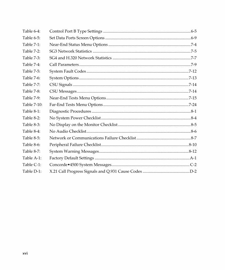
Table 6-4: Control Port B Type Settings ....................................................................................6-5
Table 6-5: Set Data Ports Screen Options ..................................................................................6-9
Table 7-1: Near-End Status Menu Options ...............................................................................7-4
Table 7-2: SG3 Network Statistics ..............................................................................................7-5
Table 7-3: SG4 and H.320 Network Statistics ...........................................................................7-7
Table 7-4: Call Parameters...........................................................................................................7-9
Table 7-5: System Fault Codes ..................................................................................................7-12
Table 7-6: System Options .........................................................................................................7-13
Table 7-7: CSU Signals ...............................................................................................................7-14
Table 7-8: CSU Messages ...........................................................................................................7-14
Table 7-9: Near-End Tests Menu Options...............................................................................7-15
Table 7-10: Far-End Tests Menu Options..................................................................................7-24
Table 8-1: Diagnostic Procedures ...............................................................................................8-1
Table 8-2: No System Power Checklist ......................................................................................8-4
Table 8-3: No Display on the Monitor Checklist......................................................................8-5
Table 8-4: No Audio Checklist....................................................................................................8-6
Table 8-5: Network or Communications Failure Checklist ....................................................8-7
Table 8-6: Peripheral Failure Checklist....................................................................................8-10
Table 8-7: System Warning Messages......................................................................................8-12
Table A-1: Factory Default Settings ...........................................................................................A-1
Table C-1: Concorde¥4500 System Messages...........................................................................C-2
Table D-1: X.21 Call Progress Signals and Q.931 Cause Codes .............................................D-2
xvi

About This Guide
This guide explains how to conÞgure general, video, audio, and network options for the Concorde¥4500ª. It also describes how to connect the system to a network, interpret system messages, and resolve problems.
You should use this guide if you are responsible for conÞguring and adjusting the system. You should be familiar with installing electronic and data communications equipment.
For support or service, please contact your PictureTel service provider or call PictureTel Technical Support. You can Þnd phone numbers for Technical Support in your area at the PictureTel web site, www.picturetel.com.
xvii


Introducing theConcorde¥4500

This chapter describes
❑ The Concorde¥4500 system components
❑ The Concorde¥4500 menu system
❑ Using online help
❑ Setting up the Concorde¥4500 UserÕs Notebook

1
Introducing theConcorde¥4500The Concorde¥4500 is a state-of-the-art videoconferencing system that enables you to conduct face-to-face meetings with people anywhere in the world. You see full-motion video and hear high- quality audio while you communicate as if you were all in the same room.
This chapter brießy describes each of the major Concorde¥4500 components so that you can familiarize yourself with your system. It also explains how to use the Concorde¥4500 menu system, access online help, and set up the Concorde¥4500 UserÕs Notebook.
1-1

INTRODUCING THE CONCORDE¥4500
HereÕs an illustration of the Concorde¥4500 with its components.
Figure 1-1: Concorde•4500 System Components
Wireless
PowerMicLook-At-Me-Button
Monitor
keypad
QuickPad
3DEF
2ABC
1
6MNO
5JKL
4GHI
9WXYZ
8TUV
7PQRS
#0
CANCEL
SNAPSHOTNEAR ENDFAR END PIP
VCRDOCMAIN SNAPSHOT
SET
FAR END
POINTZOOM
MUTE VOLUME
NEAR END
SHOW ROOMPRESETS
ENTER
PRINTSETUPSTATUSHELP
CALL/ADD
HANG UP
VIEW
SEND
ADJUST
1 2
WorldCart
PowerCam 100
LimeLight
SENDSNAPSHOT
VIEWFAR END
BROWSE
RECIEVE
SEND
PREVIEW
RECALLSNAPSHOT
A B
VCRAUXAUXDOCMAIN
0
7PQRS
8TUV
9WXYZ
4GHI
5JKL
6MNO
1 2ABC
3DEF
#
?
12 3
4
FAREND
12 3
SET
NEAREND
SET
CHOOSECALL / ADD
SETUP
LOW BATTERY
HELP
STATUS
MUTE PIP
HANG UP
ENTER CANCEL
ZOOMPOINT
AUTOMATIC
ZOOMPOINT
AUTOMATIC
SHOWROOM
1-2

Wireless Keypad
Wireless Keypad The wireless keypad controls the videoconferencing system by sending infrared signals to the receiver on your main camera. Using the wireless keypad, you can adjust the sound you hear, send video images from a camera, or change the cameraÕs view.
The keypad is divided into the basic sections illustrated below.
Figure 1-2: Wireless Keypad
F Y I F.Y.I. You need the wireless keypad to use the browse, director, and chair control modes in multipoint calls.
SENDSNAPSHOT
VIEWFAR END
BROWSE
RECIEVE
SEND
PREVIEW
RECALLSNAPSHOT
A B
VCRAUXAUXDOCMAIN
0
7PQRS
8TUV
9WXYZ
4GHI
5JKL
6MNO
1 2ABC
3DEF
#
?
12 3
4
FAREND
12 3
SET
NEAREND
SET
CHOOSECALL / ADD
SETUP
LOW BATTERY
HELP
STATUS
MUTE PIP
HANG UP
ENTER CANCEL
ZOOMPOINT
AUTOMATIC
ZOOMPOINT
AUTOMATIC
SHOWROOM
Far End
Near End
Administration
Dialing
ConferenceControl
Information
Image Control
Image Control
1-3

INTRODUCING THE CONCORDE¥4500
QuickPad The QuickPadª is available as an option for the Concorde¥4500. Like the wireless keypad, it controls the videoconferencing system by sending infrared signals to the receiver on your main camera. With the QuickPad, you can perform almost all of the functions available from the wireless keypad, such as adjusting sound, sending video images, or changing the cameraÕs view.
The QuickPad is divided into the basic sections illustrated below.
Figure 1-3: QuickPad
3DEF
2ABC
1
6MNO
5JKL
4GHI
9WXYZ
8TUV
7PQRS
#0
CANCEL
SNAPSHOTNEAR ENDFAR END PIP
VCRDOCMAIN SNAPSHOT
SET
FAR END
POINTZOOM
MUTE VOLUME
NEAR END
SHOW ROOMPRESETS
ENTER
PRINTSETUPSTATUSHELP
CALL/ADD
HANG UP
VIEW
SEND
ADJUST
1 2
Administration/Information
Dialing
Image Control
Audio Control
Use these buttonsto toggle betweenNEAR END andFAR ENDimage control
1-4
Monitors
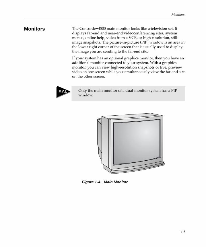
Monitors The Concorde¥4500 main monitor looks like a television set. It displays far-end and near-end videoconferencing sites, system menus, online help, video from a VCR, or high-resolution, still- image snapshots. The picture-in-picture (PIP) window is an area in the lower right corner of the screen that is usually used to display the image you are sending to the far-end site.
If your system has an optional graphics monitor, then you have an additional monitor connected to your system. With a graphics monitor, you can view high-resolution snapshots or live, preview video on one screen while you simultaneously view the far-end site on the other screen.
Figure 1-4: Main Monitor
F Y I F.Y.I. Only the main monitor of a dual-monitor system has a PIP window.
1-5

INTRODUCING THE CONCORDE¥4500
Electronics Module
The electronics module is a self-contained unit that includes the system electronics, the system software cartridge, and the power supply. The back of the electronics module exposes the connection panel where the cables connect to the system. The electronics module sits in the bottom of the WorldCartª.
Figure 1-5: Electronics Module
Electronics module
1-6

Cameras
Cameras The PowerCamª 100, used as the main camera for the Concorde¥4500, is a compact, modular, pan-tilt-zoom (PTZ) camera. It has an infrared signal receiver that enables you to control your videoconference from the keypad. The camera is Þxed to the top of the monitor.
You may also have an auxiliary camera, which is typically a pan-tilt-zoom camera mounted on a tripod. This camera is particularly useful when you want to focus on a conference room tool, such as a ßip chart or an exhibit.
Figure 1-6: PowerCam 100
Infrared receiver
1-7

INTRODUCING THE CONCORDE¥4500
LimeLight LimeLightª is an automatic, camera-pointing device that senses voices in a room and points the camera towards the speaker. LimeLight automatically calculates the correct pan angle, tilt angle, and zoom range of the camera. If two or more people in the room get into a conversation, LimeLight adjusts to include all speakers in the frame.
For ideas on how to use automatic camera pointing most effectively, see ÒTips for Using LimeLightÓ under the Tips tab in the Concorde¥4500 UserÕs Notebook.
Figure 1-7: LimeLight
LimeLight
PowerCam 100
1-8

Microphones
Microphones The Concorde¥4500 uses the PowerMic , a domed circular microphone that is placed on your conference room table. It connects to the back of the electronics module. You can use more than one PowerMic if you have a large conference room. In fact, you can serially connect up to four PowerMics for use with your system. The PowerMic is packaged with its own documentation, which describes how to install and use it.
The PowerMic equalizes sound. Loud voices, soft voices, and even whispers are picked up and transmitted to the far end at approximately the same volume.
If you choose to walk around the room during a videoconference, you may want to use the optional lapel microphone.
Figure 1-8: PowerMic
1-9

INTRODUCING THE CONCORDE¥4500
WorldCart The WorldCart is a fully-integrated, roll-about cart for the Concorde¥4500. The system monitor attaches to the top of the cart. A pull-out drawer, located behind the front doors, provides storage for the PowerMic, wireless keypad, Look-At-Me-Buttonª (LAMBª), and the Concorde¥4500 documentation.
The electronics module sits in the lower portion of the cart. Shelves are available to hold additional items, such as a modem or a VCR. A Bose¨ speaker is built into the front of the cart.
If your system also has a graphics monitor, the second monitor may be attached to another WorldCart. The second cart is similar to the main cart except that it does not contain an electronics module or Bose speakers.
Figure 1-9: WorldCart
PowerMic
Wirelesskeypad
Look-At-Me-Button
Bose speaker
Documentation
1-10

Look-At-Me-Button
Look-At-Me-Button
The Look-At-Me-Button is a wireless device that allows you to preset camera views with the Concorde¥4500. You can mount the LAMB on a wall near a whiteboard or other point of interest, or place it on your conference room table. The large blue button in the center of the LAMB works just like the camera preset buttons on your keypad.
The LAMB has two other buttons, MUTE and SHOW ROOM. Pressing MUTE blocks sound from your microphones, so that no sound is sent to the far end. Pressing SHOW ROOM moves your main camera back to a wide-angle room view.
Figure 1-10: Look-At-Me-Button
LOW BATTERY
MUTE
SHOW
ROOM
1-11

INTRODUCING THE CONCORDE¥4500
Optional Equipment
You can add optional equipment to the Concorde¥4500 by contacting your PictureTel sales representative. Here are some options:
❑ VCRs Ñ You can add one or two VCRs to your system to play or record video and audio during your videoconference.
❑ T.120 peripherals Ñ You can add T.120 devices to your system, such as GroupBoardª and LiveShare Plusª, to enable you to participate in dataconferences.
❑ Additional Look-At-Me-Buttons Ñ You can use additional LAMBs with your system for multiple preset camera views.
❑ Additional cameras Ñ You can use additional cameras with your system, such as auxiliary PTZ cameras or document cameras. A total of four cameras, including the main camera, can be connected to your system.
❑ Additional microphones and speakers Ñ You can add audio peripherals to your system to further enhance the audio quality of your meetings.
❑ Other videoconferencing meeting tools Ñ You can add a document conferencing projector, a scanner, or a video scan converter used in combination with a personal computer to your system.
❑ Additional keypads Ñ You can use additional wireless keypads or QuickPads with your system to give more participants the ability to control the videoconference.
1-12

Using the Concorde¥4500 Menu System
Using the Concorde•4500 Menu System
This section provides information that you need to know to use the Concorde¥4500 menu system. Topics include:
❑ Using the Setup menu
❑ Navigating through the menus
❑ Using the character grid to enter information
Using the Setup MenuWhen you press SETUP on the keypad, the Setup menu appears:
The Setup options are documented in the following chapters:
❑ Modify Dialing Directory (Chapter 3)
❑ View Configuration Menu (Chapter 4)
¥ Set General Configuration (Chapter 4)
¥ Set Video Configuration (Chapter 5)
¥ Set Audio Configuration (Chapter 5)
¥ Set Data Port Configuration (Chapter 6)
¥ Set Network Configuration (Chapter 2)
¥ Restoring Default Configuration (Chapter 4)
❑ View Diagnostic Menu (Chapter 7)
❑ View System Configuration (Chapter 7)
❑ View Call Log (Chapter 7)
Add, delete, or change the contents of the Dialing Directory
Configure the system settings
Conduct tests to troubleshoot or verify system integrity
See the system configuration settings in one convenient screen
See call progress messages for the most recent call and the last 100 failed calls
Setup Menu
Modify Dialing DirectoryView Configuration MenuView Diagnostics MenuView System ConfigurationView Call Log
1-13

INTRODUCING THE CONCORDE¥4500
You can also reset the system to its default settings. See ÒRestoring Default SettingsÓ on page 4-18.
Navigating Through the MenusUse and to select a menu item and then press ENTER to activate it.
In many cases, activating the menu item causes another menu to appear, listing the choices for that menu. Again, use and to select an item from the menu and press ENTER to activate it.
If a menu continues onto another screen, arrows appear on the current screen:
❑ Use and to move from screen to screen.
❑ Use and to scroll up and down the list of menu items.
Any time a menu appears, you can go back to the previous menu by choosing View Previous Menu or you can exit the menu system by pressing CANCEL.
Using the Character Grid to Enter InformationWhen you need to enter alphanumeric information, such as names for Dialing Directory entries, the character grid appears:
To enter information using the character grid:
❑ Use and to select the character you want.
❑ Press ENTER to accept the character.
❑ If you need to delete a character, use the arrows to select the backspace icon and press ENTER.
❑ If you want to add a blank space, select the space icon and press ENTER. It is located immediately above the icon.
❑ When you are Þnished entering the site name, select the icon and press ENTER.
ABCDEFGHIJKLMNOPQRSTUVWXYZÃÄÇÉÏÑÖÜa
FINbcd e f g hi j k l mn op q r s t u vw x yz @#$&’/-_
aa aa ceee i i i i n o o o ou u uuß 012 3 45678 9^ .. ^ .. ^ ..^ ..^
Space
FIN
1-14

Using Online Help
Using Online Help
The Concorde¥4500 has online help that you can view on your monitor before, during, or after a videoconference. These help screens appear when you press HELP on the keypad. The help screens explain how to perform various topics and tasks, such as how to make a call.
You can use online help anytime there are no other menus displayed on the screen.
To access online help:
1. Press HELP.
The Help menu appears:
2. Use to select a topic.
3. Press ENTER.
Follow the on-screen instructions to Þnd help on a topic or task.
To exit online help:
Press CANCEL.
Help
Using HelpNew Features in Software Version 6.30Making a CallAnswering and Hanging Up a CallControlling AudioControlling VideoDisplaying System InformationUsing MultipointUsing the Dialing DirectoryAbout the Concorde•4500
1-15

INTRODUCING THE CONCORDE¥4500
Supplying Information for the User’s Notebook
The Concorde¥4500 UserÕs Notebook documents the topics and tasks the average user needs to know to videoconference successfully. For this reason, PictureTel recommends that you leave the notebook in the same room as the Concorde¥4500.
The Concorde¥4500 UserÕs Notebook includes:
❑ A Quick Reference section
❑ Basic information on how to make and receive calls
❑ Guidelines for adjusting cameras and sound
❑ Videoconferencing tips
❑ Multipoint videoconferencing information
It also contains worksheets where you can list:
❑ Frequently called video numbers
❑ System information
❑ Help numbers
These worksheets provide a place for you to list information speciÞc to your system which may prove useful to anyone who uses it. Before placing the Concorde¥4500 UserÕs Notebook in the room with the Concorde¥4500, Þll in the following information:
You can include any additional information on the Notes worksheet.
Table 1-1: User’s Notebook Checklist
✓ Information
Your name and phone number (you should also record your phone number in the Quick Reference section)
Phone number for the PictureTel service provider
Phone number for the network provider
System information, including network type and conÞguration information
Information about other systems that may be called frequently from this system
1-16
Supplying Information for the UserÕs Notebook
The Concorde¥4500 UserÕs Notebook also contains menu trees and troubleshooting information, so that you will have that information readily accessible in the conference room without needing to reference this Concorde¥4500 AdministratorÕs Guide.
1-17


Connecting andConÞguring Your
Network

This chapter describes how to
❑ Attach digital network cables
❑ Attach telephone network cables
❑ Access the Network ConÞguration menu
❑ Select a network interface
❑ ConÞgure Auto IMUX Dialing
❑ Select an answer mode
❑ ConÞgure two-line dialing
❑ Enable and conÞgure H.331 broadcasting

2
Connecting andConÞguring YourNetwork
This chapter explains how to connect to and conÞgure the network interfaces you can use with the Concorde¥4500.
You can connect your system to one of the following digital network interfaces:
❑ Internal four-wire CSU
❑ V.35
❑ RS-449
❑ X.21
❑ Northern Telecom V.25 bis
Before reading this chapter, here are some terms you may want to know:
❑ CSDC (Circuit Switched Data Capability) Ñ A circuit-switched, 56 kbps, full duplex data service that allows data communication over regular telephone lines.
❑ DDS (Dataphone Digital Service) Ñ A private line digital service used for data transmission up to 56 kbps.
❑ Switched-56 Ñ A switched network service that operates with 56 kbps channels. A typical call on this network uses two channels, and thus transmits data at a rate of 112 kbps.
F Y I F.Y.I. If a POTS daughter board is present, you can also connect a two-wire telephone line to your system.
2-1

CONNECTING AND CONFIGURING YOUR NETWORK
❑ ISDN (Integrated Services Digital Network) Ñ A set of transmission standards designed to ensure compatibility between digital communications services worldwide.
❑ T1 Ñ An AT&T term for a digital carrier used in the U.S. and Japan to transmit a DS1 formatted digital signal at 1.544 megabits per second or 1.536 megabits per second using Clear Channel Capability. A T1 line can carry up to 24 total channels at 64 kbps.
❑ E1 Ñ A European digital transmission facility used to transmit a digital signal at 2.048 Mbps. An E1 line can carry up to 32 channels at 64 kbps.
Attaching Digital Network Cables
This section describes the network interfaces and provides procedures and illustrations for connecting to each network. Refer to the procedure for the network you are using with the Concorde¥4500. You may also refer to the Concorde¥4500 Servicing Guide for information on pin assignments.
Internal Four-Wire Channel Service Unit (CSU)The Concorde¥4500 supports an internal CSU daughter board for connecting to a CSDC 56-kilobit network or to a four-wire DDS line. The internal CSU interface also provides an RS-449 connector to support the concurrent connection of the system to both a switched and a dedicated network.
The wires in the four-wire switched interface are used as follows: two wires transmit data, and two wires receive data.
You must follow these guidelines when providing the cable:
❑ Bring the four unused conductors out to the connector.
❑ Use an RJ-48S jack at the termination point of the extended demarc.
F Y I F.Y.I. The Concorde¥4500 does not use the four remaining conductors.
2-2

Attaching Digital Network Cables
To connect your system to a dialed CSDC network or to a nondialed DDS network interface:
1. Uncoil the network cables.
2. Plug the RJ-48S cable leads into the network wall jacks.
3. Plug the network cable RJ-48S connector into the PSDN connections on the Communications board 4 WIRE SW-56 panel on the back of the electronics module, as shown in Figure 2-1.
Make sure that the cable from the network wall jack for the Þrst line connects to Port 1 on the connection panel.
Figure 2-1: CSU Network Connection Panel
PORT
1
PORT 2
4 WIRESW-56
PSDN
DTR
DCD
RTS
CTS
TXD
RXD
NS
PRIVATENETWORKRS-449
CTRLA
PSDN
DTR
DCD
RTS
CTS
TXD
RXD
NS
CTRLB
2-3

CONNECTING AND CONFIGURING YOUR NETWORK
4. Make sure that the LED states on the connection panel match those on the following table
If the LED states do not match, call the network provider.
To connect your system to a nondialed RS-449 network:
Plug the RS-449 cable DC-37 connector into the Communications board.
Table 2-1: Connection Panel LED States
Lit Unlit
DTR
DCD
RTS
CTS
TXD
RXD
NS
T I P
If your system is connected to both a dialed and a nondialed network and is conÞgured to SW-56 Dialed/RS-449 Nondialed, you can conÞgure the system to RS-449 Nondialed for a single call, as follows:
1. Press the CALL/ADD button on the keypad.
2. Choose Nondialed line.
Terminating the call restores the system to Switched-56 Dialed operation.
2-4

Attaching Digital Network Cables
V.35 Network InterfaceThe ITU-T V.35 interface operates at data rates that range from 56 through 768 kbps. An associated RS-366A interface supports dialing. Most manufacturers of CSUs provide an RS-366A dialing port with the V.35 interface, making the V.35 popular for connecting to switched networks.
The Concorde¥4500 conÞgured with a V.35 interface supports ISDN terminal adapters, multiplexers, and other network terminating equipment, such as modular processor data modules (MPDMs) and Northern Telecom DPUs.
PictureTel provides the RS-366 cables. In addition, PictureTel provides two female DC-37 to M-34 adapter cables. The adapter cables are connected to the male DC-37 connectors on the electronics modules.
You must follow these guidelines when providing the cable:
❑ Use a cable length that does not exceed 100 feet (30.5 meters) between the system and the network (with any bit rate).
❑ Use a Belden 9732 (or equivalent) cable.
❑ Provide an M-34 male connector.
2-5

CONNECTING AND CONFIGURING YOUR NETWORK
To connect your system to a V.35 network interface:
1. Connect the two network cables to the two M-34 connectors on the V.35 adapter cables.
2. Plug the DC-37 connectors on the two adapter cables into the CHAN connectors on the Communications board V.35 network panel, as shown in Figure 2-2.
Take care when aligning the connectors.
Port 1 on the electronics module must interface with the lowest numbered or lettered port on the network interface device.
Figure 2-2: Adapter Cable and Connection Panel for a V.35 Network Interface
3. Tighten the screws on the connectors.
4. Connect the RS-366 cables to the DIAL connectors next to the CHAN connectors.
V.35
CTRLA
CTRLB
CHAN
CHAN
DIAL
DIAL
PORT 1
PORT 2
DC-37 connector
M-34 connector
2-6

Attaching Digital Network Cables
5. Connect the other end of each RS-366 cable to the RS-366 dial ports on the terminal adapter or other network terminating equipment.
RS-449 Network InterfaceThe RS-449 channel port transmits data signals using the RS-422 balanced line data transmission standard. This interface operates at the following bit rates:
❑ 56 kbps through 768 kbps with ITU-T Recommendation H.320 and SG4ª
❑ 56 kbps through 768 kbps with SG3ª
You must follow these guidelines when providing the cable:
❑ Use a Belden 9737 (or equivalent) cable
❑ Provide a cable that is no longer than 1,000 feet (450 meters) between the system and the network at 384 kbps
❑ Provide a DC-37 female connector to mate with the male RS-449 connector on the back of the electronics module, as shown in Figure 2-3
Figure 2-3: RS-449 Interface DC-37 Connector on the Electronics Module
F Y I F.Y.I. When the Concorde¥4500 is set to nondialed mode, it asserts TR and RS. If the DCE requires either of these signals, that signal may have to be provided in the cable. A larger cable, such as a Belden 9732, is then required.
1 2 3 4 5 6 7 8 9 10 11 12 13 14 15 16 17 18 19
20 21 22 23 24 25 26 27 28 29 30 31 32 33 34 35 36 37
2-7

CONNECTING AND CONFIGURING YOUR NETWORK
To connect your system to an RS-449 network interface:
1. Plug the network cables into the DC-37 CHAN connectors on the Communications board RS-449 network panel, as shown in Figure 2-4.
Take care when aligning the connectors.
Figure 2-4: RS-449 Network Connection Panel on the Communications Board
2. Tighten the screws on the connectors.
RS-449
CTRLA
CTRLB
CHAN
CHAN
DIAL
DIAL
PORT 1
PORT 2
2-8

Attaching Digital Network Cables
X.21 Network InterfaceThe ITU-T X.21 interface:
❑ Provides serial automatic dialing
❑ Operates at bit rates that range from 56 kbps through 768 kbps for dialed and nondialed networks
❑ Controls network dialing
The Concorde¥4500 conÞgured with an X.21 interface supports ISDN terminal adapters, inverse multiplexers, and other network terminating equipment.
The maximum separation between the Concorde¥4500 and the network for dialed networks at 64 kbps is 4,000 feet (1,200 meters) and for nondialed networks at 384 kbps is 820 feet (250 meters).
You must follow these guidelines when providing the cable:
❑ Use a Belden 9732 (or equivalent) cable
❑ Provide a DA-15 female connector to mate with the male DA-15 connector on the back of the electronics module, as shown in Figure 2-5
Figure 2-5: X.21 Interface Connector on the Electronics Module
F Y I F.Y.I. You need an X.21 network connection to receive the X.21 call progress messages. For more information, see Appendix D, ÒX.21 Call Progress Messages.Ó
1 2 3 4 5 6 7 8
9 10 11 12 13 14 15
2-9

CONNECTING AND CONFIGURING YOUR NETWORK
To connect your system to an X.21 network interface:
1. Plug the network cables into the PORT 1 and PORT 2 connectors on the Communications board X.21 network panel, as shown in Figure 2-6.
Take care when aligning the connectors.
Port 1 on the electronics module must interface with the lowest numbered or lettered port on the network interface device.
Figure 2-6: X.21 Network Connection Panel on the Communications Board
2. Tighten the screws on the connectors.
X.21
CTRLA
CTRLB
PORT2
PORT1
2-10

Attaching Digital Network Cables
V.25 bis Network InterfaceThe Northern Telecom ITU-T V.25 bis network interface provides serial automatic dialing.
This interface is designed for use only with those Northern Telecom high-speed (64 kbps) DATAPATH Data Units that support the V.25 bis protocol, such as the Model NT4X25AG. Depending on the number of lines conÞgured with your system, you may need to connect to two Data Units. You must set the switches on each Data Unit in accordance with the parameters that Northern Telecom has speciÞed for your installation.
You can place calls with your V.25 bis system in one of two ways:
❑ From the system keypad:
Refer to the Concorde¥4500 UserÕs Notebook for procedures on how to make video calls.
❑ From the Data Unit keypad:
Refer to the Northern Telecom Meridian Data Services: Data Unit User Guide (P0673940-S943) for instructions for how to test and operate the Data Unit.
Connecting the CablesTo connect your V.25 bis network interface to the Data Unit:
1. Plug the M-34 connector on the adapter cable into the connector on the back of the Data Unit, shown in Figure 2-7.
Figure 2-7: Data Unit Connection Panel
2-11

CONNECTING AND CONFIGURING YOUR NETWORK
2. Plug the DA-15 connector on the adapter cable into the PORT 1 connector on the Communications board V.25 bis network panel, as shown in Figure 2-8.
Figure 2-8: V.25 bis Network Connection to the Data Unit
3. Repeat steps 1 and 2 for a second cable, if available, by connecting the second Data Unit to the PORT 2 connector.
4. Tighten the screws on the connectors.
5. Follow the instructions in the Meridian Data Services: Data Unit User Guide (P0673940-S943) , and plug the power cords for the Data Units into an AC power source.
The Data Unit powers on and performs a self test. When the test completes, you see the Power and Sync lights steadily lit. You also see the Sync light under MODE steadily lit.
V.25 bis
CTRLA
CTRLB
PORT2
PORT1
DA-15 connector
M-34 connector
2-12

Attaching Digital Network Cables
If you see the Power light ßashing, check the connections on the network cable and make sure that the cable is properly and securely connected.
Setting Data Unit Switches
Follow these conventions when you are setting the Data Unit switches:
❑ If at any time after you have pressed Settings you want to revert all settings to their previously set values, press ✱ on the Data Unit keypad.
❑ If you want to cancel a choice, press ✱ again.
F Y I F.Y.I. PictureTel assumes no responsibility for technical or editorial errors or for omissions that may appear in the Data Unit switch settings. Nor does PictureTel make any commitment to update the information.
2-13

CONNECTING AND CONFIGURING YOUR NETWORK
Attaching Audio Telephone Network Cables
If a POTS daughter board is present, you can connect a two-wire telephone line to the Concorde¥4500, as follows:
1. Plug the telephone network cable into the phone wall connector on the Audio board, shown in Figure 2-9 .
2. Plug the cable from the telephone into the phone set connector on the Audio board, shown in Figure 2-9 .
Figure 2-9: Audio Board Connectors
8AUDIO
A
B
7
Phone set
Phone wall
2-14

Using the Network ConÞguration Menus
Using the Network Configuration Menus
The following sections describe how to conÞgure the network interfaces for your system. To access the network conÞguration menus:
1. Press SETUP.
2. Choose View Configuration Menu .
3. Choose Set Network Configuration .
When you choose Set Network Configuration from the ConÞguration menu, a Set Network ConÞguration menu similar to this appears:
Setting a Network InterfaceThe Network Interface options establish the connection mode and conÞgure Auto IMUX Dialing for the Concorde¥4500.
Auto IMUX Dialing lets users make calls and create Dialing Directory entries without entering the extra digits required to conÞgure an inverse multiplexer (IMUX). It also reduces or eliminates the need for users to know about the rates involved.
For tips on using Auto IMUX Dialing most effectively, see ÒUsing Auto IMUX DialingÓ on page 3-7.
Set Network Configuration
View Previous MenuSet Network InterfaceSelect Answer ModeSet Two-Line Dialing [Delayed]Configure H.331 Broadcast [Disabled]
Set the connection mode and Auto IMUX Dialing
Set the mode for answering incoming calls
Set delayed dialing for a second line
Transmit one-way video and audio from one site to many sites
F Y I F.Y.I. If the Concorde¥4500 is not connected to an IMUX, or is set to a nondialed mode, Auto IMUX Dialing is not available.
2-15

CONNECTING AND CONFIGURING YOUR NETWORK
When you choose Set Network Interface from the Set Network ConÞguration menu, the Set Network Interface menu appears:
The default network interface settings are as follows:
Set Network Interface
View Previous MenuSelect Interface [Dialed]Select IMUX Type [Promptus]Set IMUX CodesSet Call RatesLet User Change Call Rate [No]Convert Dialing Directory Numbers
Set the connection mode
Set the type of IMUX used
Enter or modify the code associated with each IMUX rate
Associate a specific rate with each rate setting
Set whether users can choose rates from the Dialing Directory
Convert Dialing Directory Entries for Auto IMUX Dialing
F Y I F.Y.I. The following options are available only when Select IMUX Type is set to any setting other than None: Set IMUX Codes, Set Call Rate, Let User Change Call Rate, and Convert Dialing Directory Numbers.
The Set Code Placement option appears when Select IMUX Type is set to Other.
Setting Default
Select Interface Dialed
Select IMUX Type None
Let User Change Call Rate No
2-16

Using the Network ConÞguration Menus
Selecting an InterfaceTo select the connection mode for your interface board:
1. From the Set Network Interface menu, choose Select Interface .
A Select Interface screen similar to this one appears, depending on your network conÞguration:
2. Choose the setting you want.
An [X] appears next to the new setting.
Select Interface
View Previous MenuDialedNondialed
(V.35 board present)
F Y I F.Y.I. A V.25 bis network interface must be set to Dialed. If you choose Nondialed, an error message appears.
T I P
If your system is connected to both a dialed and a nondialed network and is conÞgured to SW-56 Dialed/RS-449 Nondialed, you can conÞgure the system to RS-449 Nondialed for a single call as follows:
1. Press CALL/ADD .
2. Choose Nondialed Line.
Terminating the call restores the system to Switched-56 Dialed operation.
2-17

CONNECTING AND CONFIGURING YOUR NETWORK
Selecting the IMUX TypeChoose Select IMUX Type from the Set Network Interface menu to determine the type of IMUX connected to the Concorde¥4500, as follows:
Table 2-2: Select IMUX Type Menu Options
Setting Description
None Indicates that either no IMUX is present or you do not want to use Auto IMUX Dialing.
Promptus Initializes the IMUX codes to the default settings for Promptus. Note that you must conÞrm the initialization strings or the codes are left blank (the factory default).
Ascend Initializes the IMUX codes to the default settings for Ascend. Note that you must conÞrm the initialization strings or the codes are left blank (the factory default).
Madge Initializes the IMUX codes to the default settings for Madge. Note that you must conÞrm the initialization strings or the codes are left blank (the factory default).
Adtran Initializes the IMUX codes to the default settings for Adtran. Note that you must conÞrm the initialization strings or the codes are left blank (the factory default).
Other Indicates that the IMUX is from a manufacturer other than those listed. You must specify whether the IMUX codes are preÞxes or sufÞxes. See ÒLetting Users Change the Call RateÓ on page 2-20.
2-18

Using the Network ConÞguration Menus
Setting IMUX CodesChoose Set IMUX Codes from the Set Network Interface menu to enter or modify the dialing strings associated with each of the IMUX rates. By default, these codes are blank. However, if you set Select IMUX Type to Promptus, Ascend, Adtran, or Madge and you conÞrmed the initialization strings, the codes are set to the default settings for the type of IMUX you conÞgured.
To enter or modify an IMUX code:
1. Select the code you want to modify.
A text Þeld appears.
2. Press to delete the existing code, if necessary.
3. Enter the new code.
An IMUX code can consist of up to eight characters.
Once you set an IMUX code, it is maintained until you restore the system default settings.
Setting Code PlacementSome manufacturers develop IMUXes that look for IMUX codes at the beginning of a video number, while others develop ones that look for them at the end of a video number.
When you choose one of the manufacturers listed in the Select IMUX Type menu, the Concorde¥4500 automatically recognizes where the code should be located.
But when you set the IMUX type to Other, you must specify whether the IMUX code is a preÞx or a sufÞx.
To set the IMUX code placement:
1. From the Set Network Interface menu, select Set Code Placement .
2. Press ENTER to toggle between Prefix and Suffix .
F Y I F.Y.I. If your IMUX allows you to associate codes with speciÞc transmission rates, these codes must match the IMUX codes you set for the Concorde¥4500.
2-19

CONNECTING AND CONFIGURING YOUR NETWORK
Setting Call RatesChoose Set Call Rates from the Set Network Interface menu to set speciÞc transmission rates for the two system call settings: Premium and Standard. You can also choose one of these settings to serve as the system default for manually dialed calls.
The default rates are as follows:
Letting Users Change the Call RateChoose Let User Change Call Rate from the Set Network Interface menu to enable or disable the Change Rate for This Call option in the Dialing Directory. The Change Rate for This Call option allows users to choose the rate for the next call.
To enable or disable the Change Rate for This Call option:
1. From the Set Network Interface menu, select Let User Change Call Rate.
2. Press ENTER to toggle between Yes and No.
Converting Dialing Directory NumbersIf you want to conÞgure the Concorde¥4500 for Auto IMUX Dialing and the video numbers in the Dialing Directory contain embedded IMUX codes, you must remove these codes for Auto IMUX Dialing to work most effectively.
The Convert Dialing Directory Numbers menu choice provides a conversion routine to simplify this process. The routine removes the IMUX code from the number itself and stores it as a separate item in the Dialing Directory entry. This conversion makes it much easier to change the entryÕs default rate in the future.
Setting Default
Premium 1x384
Standard 2x64
Manual Dial Default Premium
2-20

Using the Network ConÞguration Menus
To remove IMUX preÞxes from the Dialing Directory:
1. From the Set Network Interface menu, choose Convert Dialing Directory Numbers .
The conversion routine searches for known IMUX codes in the video numbers of each Dialing Directory entry.
If there is a match, the system suggests a conversion for the entry, as shown in this screen:
2. Choose Yes to accept the conversion or No to reject it.
If you select Yes, the conversion routine removes the preÞx or sufÞx from the video numbers and converts it to an IMUX code that is stored with the Dialing Directory entry. If you select No, the routine does not alter the Dialing Directory entry.
This process is repeated until the routine analyzes all of the Dialing Directory entries.
Selecting an Answer ModeBy default, your systemÕs answer mode is set to answer incoming calls manually. When your system is conÞgured with a dialed network, you can change the setting so that your system answers video and audio calls automatically.
Convert Dialing Directory Numbers
Speed dial number: *4Line 1: #025915086234000Line 2: #025915086234001
Suggested change:Rate: [2x64]Line 1: 915086234000Line 2: 915086234001
Accept this change? [Yes] [No]
2-21

CONNECTING AND CONFIGURING YOUR NETWORK
When you choose Select Answer Mode from the Set Network ConÞguration menu, the Select Answer Mode menu appears:
To change the answer mode:
1. From the Set Network Configuration menu, choose Select Answer Mode.
2. Select Video Answer Mode or Phone-Add Answer Mode .
3. Press ENTER to toggle between Manual and Automatic .
4. If you set Video Answer Mode to Automatic , the Force Mute=On for Auto-Answer option appears. Select the option and press ENTER to toggle between Yes and No.
F Y I F.Y.I. Your IMUX answer mode setting must match your system answer mode setting for calls to connect successfully.
Select Answer Mode
View Previous MenuVideo Answer Mode [Manual]Phone-Add Answer Mode [Manual]
F Y I F.Y.I. The Phone-Add Answer Mode option appears only when the Concorde¥4500 is conÞgured to allow voice-only calls.
2-22

Using the Network ConÞguration Menus
5. Type the password, if required.
An [X] appears next to the new setting.
The following table lists and describes the answer modes:
F Y I F.Y.I. By design, automatic answer mode allows your system to answer a call automatically whenever anyone calls your site.
When you set automatic answer mode on your system, be aware that a call could interrupt a meeting in progress or a caller could look at equipment and blackboard notes left in an empty room.
Table 2-3: Descriptions of Answer Mode
Answer Mode Description
Manual An incoming call
❑ Brings the system out of standby mode:
¥ Turns on the monitor or monitors
¥ Rotates the main camera from its parked position
❑ Sounds the system ringer
❑ Displays one of these messages:
¥ Incoming Video Call
¥ Incoming Voice Call
¥ Incoming Voice and Video Call
❑ Waits for your action
When you press CALL/ADD:
❑ You see the image from the far end when the system completes the connection through the network.
❑ Your system sends video and audio to the far end.
2-23

CONNECTING AND CONFIGURING YOUR NETWORK
Automatic An incoming call
❑ Brings the system out of standby mode:
¥ Turns on the monitor or monitors
¥ Rotates the main camera from its parked position
❑ Displays one of these messages:
¥ Answering Video Call
¥ Answering Voice Call
¥ Answering Voice and Video Call
❑ Displays the image from the far end when the system completes the connection through the network
❑ Sends video and audio from your system to the far end
Automatic with Mute On
An incoming call
❑ Brings the system out of standby mode:
¥ Turns on the monitor or monitors
¥ Rotates the main camera from its parked position
❑ Displays the image from the far end when the system completes the connection through the network
❑ Mutes your system. (The system sends video, but not audio, to the far end.)You must press the MUTE button to turn mute off if you want the far end to hear you.
Table 2-3: Descriptions of Answer Mode
Answer Mode Description
2-24

Using the Network ConÞguration Menus
Setting Two-Line DialingWhen a videoconferencing system is connected to some network switching equipment, primarily European, this equipment cannot answer both lines of an incoming video call simultaneously. To adjust to this situation, you can use the Set Two-Line Dialing screen to set your system to delayed dialing (the factory default setting). The system then dials a two-line video call one number at a time, as follows:
❑ Dials the Þrst number
❑ Waits until the connection is made (about 10 seconds)
❑ Dials the second number
To change the dialing mode:
1. From the Set Network Configuration menu, choose Set Two-Line Dialing .
You see these choices:
❑ Simultaneous
❑ Delayed [X]
An [X] appears next to the current setting.
2. Choose the desired setting.
An [X] appears next to the setting you chose.
Enabling and Configuring H.331 Broadcast Mode
H.331 broadcast mode is a feature that enables you to have a videoconference in which one site transmits video and audio to many sites. The receiving sites can see and hear video and audio from the sending site (the broadcaster), but the broadcaster does not receive any video or audio from the other sites. This is known as a broadcast transmission Ñ in other words, a one-way transmission.
When the H.331 broadcast mode feature is enabled, your system can communicate with a terminal or a multipoint bridge that supports this feature. The sending site and the receiving sites must have the H.331 broadcast mode enabled on their systems to participate in the H.331 broadcast videoconference.
2-25

CONNECTING AND CONFIGURING YOUR NETWORK
To enable and conÞgure H.331 broadcast mode:
1. From the Set Network Configuration menu, choose Configure H.331 Broadcast.
A menu similar to the following menu appears:
2. Select Enable/Disable and press ENTER to toggle the setting to Enabled .
F Y I F.Y.I. When youÕre Þnished with a H.331 broadcast, make sure you disable this setting. Leaving it enabled when you make normal video calls may interfere with your ability to videoconference successfully.
Configure H.331 Broadcast
View Previous MenuEnable/Disable [Disabled]Set H.331 Video Send FormatSet H.331 Audio Send FormatSet H.331 Channel Clear or Restricted
F Y I F.Y.I. The Set H.331 Channel Clear or Restricted option appears only when the interface is set to X.21, the X.21 interface board is present, and the board is conÞgured to allow byte timing.
2-26

Using the Network ConÞguration Menus
3. Choose Set H.331 Video Send Format .
The Set H.331 Video Send screen appears with the following choices:
❑ CIF 30 fps
❑ CIF 15 fps
❑ CIF 7.5 fps
❑ QCIF 15 fps
❑ QCIF 10 fps
❑ QCIF 7.5 fps
4. Choose the appropriate setting based on the requirements for the H.331 broadcast conference.
5. From the Configure H.331 Broadcast menu, choose Set H.331 Audio Send Format .
The Set H.331 Audio Send screen appears with the following choices:
❑ PT716plus
❑ PT724
❑ G.722 56k
❑ G.722 48k
❑ G.728
❑ G.711 A-law
❑ G.711 u-law
❑ No Transmission
6. Choose the appropriate setting based on the requirements for the H.331 broadcast conference.
7. If necessary, choose Set H.331 Channel Clear or Restricted from the Configure H.331 Broadcast menu to toggle between Clear Channel and Restricted Channel .
❑ Clear Channel Ñ Select this setting if all of the sites participating in the H.331 conference are running at a network data rate of 64 kbps, or a multiple thereof.
❑ Restricted Channel Ñ Select this setting if one or more of the sites participating in the H.331 conference are running at a network data rate of 56 kbps, or a multiple thereof.
2-27


Managing theDialing Directory

This chapter describes how to
❑ Create, modify, and delete Dialing Directory entries
❑ Use Auto IMUX Dialing most effectively

3
Managing theDialing Directory
The Dialing Directory is a database that contains information about the videoconferencing sites you call. For example, each Dialing Directory entry includes the following information:
❑ The speed dial number for the site
❑ The name of the site
❑ The video numbers for the site
To view the Dialing Directory, press CALL/ADD on your keypad. A Dialing Directory screen similar to this one appears:
Dialing Directory
Manual Dial...Redial Last Video Number
_______________________________________________
No. Location Lines 1st Number
*1 BOSTON 1 7005631563*2*3
MJONESITALY
11
70086510007009991200
3-1

MANAGING THE DIALING DIRECTORY
This chapter explains how to create, modify, and delete Dialing Directory entries. It also tells you how to use Auto IMUX Dialing most effectively.
See the Concorde¥4500 UserÕs Notebook for information on how to make calls from the Dialing Directory.
Creating a Dialing Directory Entry
To create a Dialing Directory entry:
1. Press SETUP.
2. Choose Modify Dialing Directory.
The Modify Dialing Directory menu appears:
F Y I F.Y.I. You can store approximately 65 entries in your Dialing Directory (or approximately 45 international entries).
Modify Dialing Directory
View Previous MenuCreate a New EntryModify an EntryRemove an Entry
3-2

Creating a Dialing Directory Entry
3. Choose Create a New Entry .
A Create a New Entry screen similar to this one appears, which shows the next available speed dial number:
4. Enter the first number.
5. If the site has a LAN extension, press to open the LAN extension field and enter the extension.
6. Press ENTER.
7. Use one of the following methods to enter the second number:
❑ Type the number manually.
❑ Press to copy the Þrst number to the second line.
❑ Press to copy the Þrst number to the second line and increment the last digit by one.
❑ Press to copy the Þrst number to the second line, use to erase some digits, and then enter the new digits.
8. Press ENTER.
Create a New Entry
Speed dial number: *5Line 1:Line 2: NoneName: NoneRate: [None]
F Y I F.Y.I. The Rate option appears only when the Concorde¥4500 is conÞgured to use Auto IMUX Dialing.
3-3

MANAGING THE DIALING DIRECTORY
The character grid appears in the Create a New Entry screen, allowing you to name the site. The site name can contain up to eight characters.
9. Press and to move within the character grid and press ENTER to choose each character.
10. If you want to add a space to the site name, move the cursor to the space icon (located immediately above the backspace icon) and press ENTER.
11. When you are done entering the site name, select the icon, and press ENTER.
If your system is conÞgured to use Auto IMUX Dialing, the Set Call Rate screen appears, allowing you to enter the default transmission rate for the call. Refer to the next section.
If the Set Call Rate screen doesnÕt appear, the Dialing Directory entry is complete.
Create a New Entry
Speed dial number: *5Line 1: 7005631234Line 2: 7005631235Enter site name:ABCDEFGHIJKLOMNOPQRSTUVWXYZÃÄÇÉÏÑÖÜa b c de f g h i j k l m n o p q r s t u v w x y z @#$&’/-_à á a ä ç è é ê ì í î ï ñ ò ó ô ö ù ú û ü ß 0123456789
FIN
T I P
If you make a mistake while entering the site name, select the backspace icon on the screen, and press ENTER.
FIN
3-4

Modifying a Dialing Directory Entry
Choosing the Call RateIf the Set Call Rate screen appears, choose the default transmission rate for the site. This rate will override the system default rate.
To choose the rate:
1. Select Premium, Standard, Specific Rate, or Default, and press ENTER.
If you chose Premium, Standard, or Default, an [X] appears next to the setting you chose. Go to step 4. (See ÒSetting Call RatesÓ on page 2-20 to associate a transmission rate with the above settings.)
If you chose Specific Rate, the Set SpeciÞc Rate screen appears.
2. Select a rate and press ENTER.
An [X] appears next to the rate you chose.
3. Press ENTER to choose View Previous Menu and return to the Set Call Rate screen.
The rate you chose appears in brackets next to Specific Rate.
4. Press ENTER to choose View Previous Menu and return to the Modify Dialing Directory screen.
Modifying a Dialing Directory Entry
If you need to change the information in a Dialing Directory entry Ñ for example, if a site changes its video numbers Ñ you can modify the entry.
To modify a Dialing Directory entry:
1. Press SETUP.
2. Choose Modify Dialing Directory .
3-5
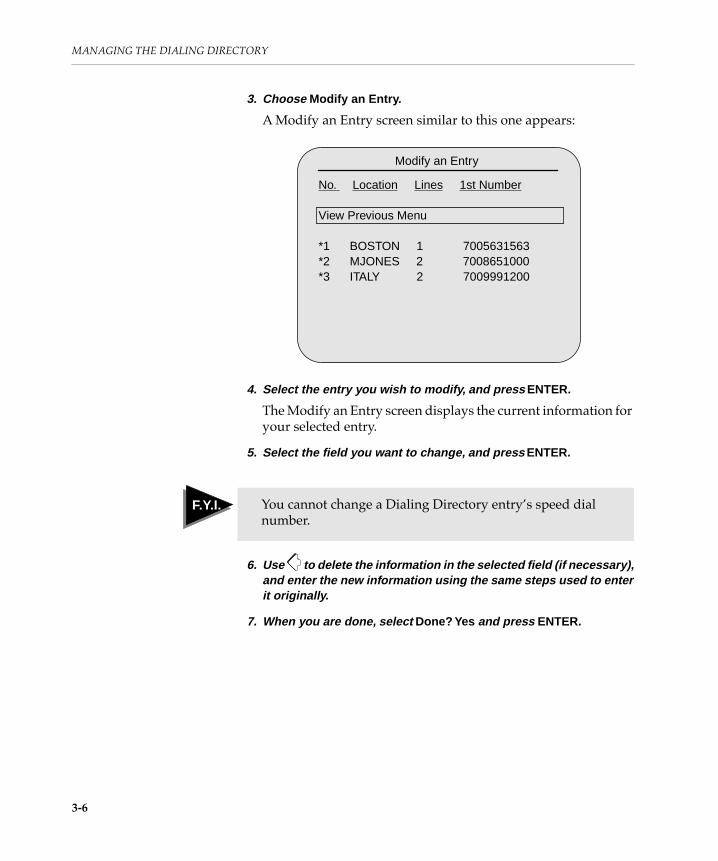
MANAGING THE DIALING DIRECTORY
3. Choose Modify an Entry .
A Modify an Entry screen similar to this one appears:
4. Select the entry you wish to modify, and press ENTER.
The Modify an Entry screen displays the current information for your selected entry.
5. Select the field you want to change, and press ENTER.
6. Use to delete the information in the selected field (if necessary), and enter the new information using the same steps used to enter it originally.
7. When you are done, select Done? Yes and press ENTER.
Modify an Entry
No. Location Lines 1st Number
View Previous Menu
*1 BOSTON 1 7005631563*2 MJONES 2 7008651000*3 ITALY 2 7009991200
F Y I F.Y.I. You cannot change a Dialing Directory entryÕs speed dial number.
3-6

Removing a Dialing Directory Entry
Removing a Dialing Directory Entry
If you no longer need a Dialing Directory entry, you can delete it.
To remove a Dialing Directory entry:
1. Press SETUP.
2. Choose Modify Dialing Directory .
3. Choose Remove an Entry .
A Remove an Entry screen similar to this one appears:
4. Select the entry you wish to remove, and press ENTER.
The Remove an Entry screen displays the current information for your selected entry.
The following message appears at the bottom of the screen:
Remove this entry? No
5. Press ENTER to remove the entry from the Dialing Directory.
Using Auto IMUX Dialing
Auto IMUX Dialing enables you to make calls or create Dialing Directory entries without entering the extra digits required to conÞgure an IMUX. It also reduces or eliminates the need for users to know about the transmission rates involved.
To conÞgure your system for Auto IMUX Dialing, see ÒSetting a Network InterfaceÓ on page 2-15.
Remove an Entry
No. Location Lines 1st Number
View Previous Menu
*1 BOSTON 1 7005631563*2 MJONES 2 7008651000*3 ITALY 2 7009991200
Yes
3-7

MANAGING THE DIALING DIRECTORY
Here are some tips to help you use Auto IMUX Dialing most effectively:
❑ If you want to conÞgure your system for Auto IMUX Dialing and the video numbers in Dialing Directory entries contain embedded IMUX codes, you should remove these codes for Auto IMUX Dialing to work most effectively. The Convert Dialing Directory Numbers screen provides a conversion routine to simplify this process. To remove embedded IMUX codes, see ÒConverting Dialing Directory NumbersÓ on page 2-20.
❑ If people in your organization call one site with multiple transmission rates, store the most common rate in the Dialing Directory. When users want to use less common rates, they can override this setting by choosing Change Rate for This Call from the Dialing Directory.
❑ If you want users to use the rates you choose when they make calls, disable the Change Rate for This Call feature by choosing Let User Change Call Rate [No] from the Set Network Interface menu.
❑ To simplify rate selection menus for users, leave the IMUX codes blank for rates that no one uses.
3-8

ConÞguringGeneral Optionsfor Your System

This chapter describes how to
❑ Set the display of far-end site names
❑ ConÞgure how messages appear on the screen
❑ Set the language
❑ Encrypt videoconferencing calls
❑ Set password protection
❑ Set the wireless keypad channel
❑ Select the AC power frequency
❑ Restore default settings

4
ConÞguringGeneral Optionsfor Your System
This chapter tells you how to conÞgure your Concorde¥4500 to suit the needs of your videoconferencing environment. You use the menus described in this chapter to set your general conÞguration.
Setting the Configuration
When you choose Set General Configuration from the ConÞguration menu, the Set General ConÞguration menu appears:
Set General Configuration
View Previous MenuSet Display of Far-End Site NameSet Screen Message DisplaySet LanguageSet Encryption ModeSet Password for MenusSet Near-End Site NameSet Standby TimerSet Wireless Keypad ChannelSelect AC Power Frequency
Set display of the far-end site name
Configure how system messages are displayed
Set the screen display language
Encrypt calls
Set password protection for the Configuration and Diagnostic menus
Name your site
Determine if and how quickly your system goes into standby mode
Indicate the AC power frequency
Set the system channel number to match the wireless keypad
4-1

CONFIGURING GENERAL OPTIONS FOR YOUR SYSTEM
The default values for settings in the Set General ConÞguration menu are:
Setting Display of the Far-End Site NameBy default, your system does not display far-end site names. If, however, you are using the SG3 video transmission format, you can set your system to display far-end site names, as follows:
Setting Default
Set Display of Far-End Site Name
Display Name Momentarily
Set Screen Message Display Display Normal Messages
Set Language English
Set Encryption Mode Disable Encryption
Set Password for Menus Disabled
Set Near-End Site Name None
Set Standby Timer 5 minutes
Set Wireless Keypad Channel 0 (All)
Select AC Power Frequency 60 Hz
Table 4-1: Display of Far-End Site Name Settings
Display Setting Description
Display Name Momentarily
(default)Displays the name of the far-end site for 10 seconds when you Þrst view that site
Display Name Displays the site name of the far-end site on the bottom of your screen throughout the videoconference
Do Not Display Name DoesnÕt display the far-end site name
4-2

Setting the ConÞguration
To conÞgure how your system displays the name of the far-end site during a videoconference:
1. From the Set General Configuration menu, choose Set Display of Far-End Site Name .
The Set Display of Far-End Site Name screen appears with the available settings.
2. Choose a display setting.
The Set Display of Far-End Site Name screen appears with an [X] next to your choice.
Setting Screen Message DisplayTo conÞgure how your system displays screen messages:
1. From the Set General Configuration menu, choose Set Screen Message Display .
The Set Screen Message Display screen appears with the available settings.
2. Choose a display selection.
The Set Screen Message Display screen appears with an [X] next to your choice.
The following table describes these settings.
F Y I F.Y.I. In multipoint videoconferences, the far-end site name appears as each participant joins the call if you have set your system to Display Name or Display Name Momentarily.
Table 4-2: Screen Message Display Settings
Display Setting Description
Display Normal Messages (default)
Provides the normal level of on-screen status messages
Display Extended Messages Provides normal status messages plus more detailed information for troubleshooting
4-3

CONFIGURING GENERAL OPTIONS FOR YOUR SYSTEM
Setting the LanguageYou can conÞgure the Concorde¥4500 to display menus and messages in English, Spanish, Portuguese, French, Italian, or German.
To set the language:
1. From the Set General Configuration menu, choose Set Language .
The Set Language menu appears:
2. Choose the desired language.
All menus and messages are displayed in the selected language.
Do Not Display Messages No messages are displayed. (You can still display status messages by pressing STATUS.)
Table 4-2: Screen Message Display Settings
Display Setting Description
F Y I F.Y.I. The Set Language menu will automatically appear every time you press the SETUP button until you set the language.
Set Language
View Previous MenuEnglishEspañolPortuguêsFrançaisItalianoDeutsch
4-4

Setting the ConÞguration
Setting Encryption Mode
When your system has the internal encryption option installed, you can conÞgure it to encrypt both dialed and nondialed (dedicated) videoconferencing calls using either automatic or manual encryption.
If your system doesnÕt have the internal encryption option, you can also conÞgure your system to use an external cryptographic device, such as KG-84, for either a dialed or a nondialed network. External devices offer an even higher level of security and can be used only with the RS-449 network interface.
The instructions in this section tell you how to use the Set General ConÞguration menu to conÞgure your system to use internal or external encryption.
The following basic guidelines apply to using encryption:
❑ The internal encryption option functions only with PictureTel System 4000 videoconferencing systems using SG3 video transmission mode.
❑ If you are attempting to make an internally encrypted call, make sure that your system has H.331 broadcast mode disabled. If your system is set for internal encryption and for H.331 broadcast mode, the system either will not complete the call or will ignore the H.331 broadcast mode and result in a point-to-point call.
❑ You can use the PictureTel internal encryption option when you must conform to the Data Encryption Standard (DES) of the United States National Bureau of Standards. Both your system and the system you call must have the encryption option installed.
❑ If you are using an external encryption device, both your system and the system you call must use identical devices.
❑ Both you and the far end must conÞgure your systems with the same encryption setting.
F Y I F.Y.I. You cannot legally export a system with the internal encryption option installed from the United States without the expressed approval of the United States Department of State. Your PictureTel sales representative can assist you.
4-5
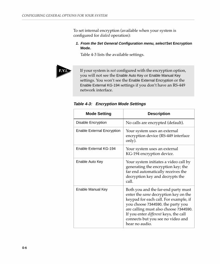
CONFIGURING GENERAL OPTIONS FOR YOUR SYSTEM
To set internal encryption (available when your system is conÞgured for dialed operation):
1. From the Set General Configuration menu, select Set Encryption Mode.
Table 4-3 lists the available settings.
F Y I F.Y.I. If your system is not conÞgured with the encryption option, you will not see the Enable Auto Key or Enable Manual Key settings. You wonÕt see the Enable External Encryption or the Enable External KG-194 settings if you donÕt have an RS-449 network interface.
Table 4-3: Encryption Mode Settings
Mode Setting Description
Disable Encryption No calls are encrypted (default).
Enable External Encryption Your system uses an external encryption device (RS-449 interface only).
Enable External KG-194 Your system uses an external KG-194 encryption device.
Enable Auto Key Your system initiates a video call by generating the encryption key; the far end automatically receives the decryption key and decrypts the call.
Enable Manual Key Both you and the far-end party must enter the same decryption key on the keypad for each call. For example, if you choose 7344590, the party you are calling must also choose 7344590.If you enter different keys, the call connects but you see no video and hear no audio.
4-6

Setting the ConÞguration
2. Do one of the following:
❑ If you want to disable all encryption, choose Disable Encryption.
The Set Encryption Mode screen appears with an [X] next to this setting.
❑ If you want to enable an external device or use either an automatically-generated decryption key or a manually-entered key, refer to the appropriate procedure in the following pages before you select Enable External Encryption, Enable External KG-194, Enable Auto Key, or Enable Manual Key.
Note: If your system is conÞgured for nondialed operation and you choose Set Encryption Mode from the Set General ConÞguration menu, or if your system is conÞgured for a dialed mode and you have a call in progress, the following message appears before you see the Set Encryption Mode settings:
You must choose Yes to continue.
Setting Encryption for an External DeviceAn external encryption device encrypts and decrypts data. If you use an external encryption device, the Concorde¥4500 does not perform encryption or decryption.
To set encryption for an external device:
1. From the Set General Configuration menu, choose Set Encryption Mode.
The Set Encryption Mode screen appears.
2. Choose Enable External Encryption or Enable External KG-194.
You might see a message asking for a password.
3. Type the system password, if required.
Warning: Call in ProgressContinuing will disconnect callContinue? YesNo
4-7

CONFIGURING GENERAL OPTIONS FOR YOUR SYSTEM
4. Press ENTER.
The Set Encryption Mode screen appears with an [X] next to the new setting.
Setting Internal Encryption for Dialed CallsThe encryption settings you make for dialed calls using the keypad override settings you make using the Set General ConÞguration menu.
To conÞgure your system to internally encrypt dialed video calls:
1. From the Set General Configuration menu, choose Set Encryption Mode.
The Set Encryption Mode screen appears.
2. Choose Auto Key or Manual Key.
You may see a message asking for a password.
3. Type the system password, if required, and press ENTER.
If you chose Auto Key, go to step 6.
If you chose Manual Key, the following message appears:
F Y I F.Y.I. External encryption enables special control signal operation on the network interface. For information on setting network interfaces, see ÒSelecting an InterfaceÓ on page 2-17.
F Y I F.Y.I. Once you choose automatic encryption using this menu, all your subsequent dialed video calls are automatically encrypted.
If you plan to use automatic encryption, you must choose the setting before you place a video call to avoid having the system disconnect the call in progress.
Manual Key
4-8

Setting the ConÞguration
4. Type the master decryption key, and press ENTER.
The decryption key can contain up to 14 numbers.
If a call is in progress, both you and the party at the far end must enter the same digits.
If you are calling a PictureTel V-3100 system, you and people using that system must both use the maximum 14 digits for the decryption key.
Once you enter the master decryption key, the system asks you to conÞrm it.
5. Retype the master decryption key, and press ENTER.
The Set Encryption Mode screen appears with an [X] next to the new setting.
6. Exit from the menu session.
During the Þrst 10 seconds of an encrypted call, you and the far-end party see the following message:
Setting Internal Encryption for Nondialed Calls
With your nondialed network call to the far-end site always connected, you must use the Set General ConÞguration menu to set encryption. When you set encryption, your call is temporarily disconnected.
To encrypt nondialed video calls:
1. From the Set General Configuration menu, choose Set Encryption Mode.
The following message appears:
2. Choose Yes to continue .
The Set Encryption Mode screen replaces the image from the far end as the call temporarily disconnects.
Encryption in Use
Warning: Call in ProgressContinuing will disconnect callContinue? YesNo
4-9

CONFIGURING GENERAL OPTIONS FOR YOUR SYSTEM
3. Choose Auto Key (at your site) or Manual Key (at both sites) .
You may see a message asking for a password.
4. Type the system password, if required, and press ENTER.
If you chose Auto Key, the Set Encryption Mode screen appears with the new setting. After a few seconds, you once again see the image from the far end. Go to step 7.
If you chose Manual Key at both your site and the far-end site, the following message appears at both sites:
5. Type the master decryption key at each site, and press ENTER.
The decryption key can contain up to 14 numbers.
If you are connected to a PictureTel V-3100 system, you and the people using that system must both use the maximum 14 digits for the decryption key.
6. Retype the master decryption key at each site, and press ENTER.
The Set Encryption Mode screen appears with an [X] next to the new setting. After a few seconds, you once again see the image from the far end.
7. Exit from the menu session.
During the Þrst 10 seconds of an encrypted call, you and the far-end party see the following message:
Manual Key
Encryption in Use
T I P
When you no longer want encryption for your nondialed video calls, you must repeat this procedure and select None from the Set Encryption Mode screen.
4-10

Setting the ConÞguration
Setting a Password for MenusThe following table lists the options when you choose Set Password for Menus from the Set General ConÞguration menu.
Enabling or Disabling the PasswordYou do not have to use password protection with the system. However, you should use a password to prevent unauthorized people from accessing most of the ConÞguration menus.
When you have enabled password protection, you can open the ConÞguration menu and submenus, but you cannot make changes to the settings and cannot get into the Diagnostics menu unless you have entered the correct password.
To enable or disable password protection:
1. From the Set General Configuration menu, choose Set Password for Menus .
2. Choose Enable or Disable Password .
The following message appears:
Table 4-4: Set Password for Menus Screen Options
Option Description
Enable or Disable Password Allows you to set password protection for the system menus or to discontinue protection.
Change Password Allows you to change the existing password or enter a new one.
T I P
If you have enabled the use of a password and have not set a speciÞc system password, use the factory-set default password, 1 2 3.
Enter CURRENT Password:
4-11

CONFIGURING GENERAL OPTIONS FOR YOUR SYSTEM
3. Type the current password, and press ENTER.
The factory default password is 1 2 3.
The following message appears:
4. Choose On or Off.
You return to the Set Password for Menus screen.
Changing the PasswordYou can use Change Password to enter a new system password or to change the current password. You should then refer to the previous section, ÒEnabling or Disabling the Password,Ó to enable password protection.
To enter a new password or to change the current password:
1. From the Set General Configuration menu, choose Set Password for Menus .
2. Choose Change Password.
The following message appears:
3. Type the current password (or the default password 1 2 3), and press ENTER.
The following message appears:
4. Type the new password using no more than six digits, and press ENTER.
The following message appears:
Password Protection: OffOn
Enter CURRENT Password:
Enter NEW Password:
Reenter NEW Password:
4-12

Setting the ConÞguration
5. Type the new password again, and press ENTER.
You return to the Set Password for Menus screen.
Setting the Near-End Site NameYou can name your site and, when the far-end system is conÞgured to display site names, display that name on the far-end screen during point-to-point and multipoint calls.
Choose any name of no more than 16 alphanumeric characters. You might use your own name or the name of your conference room or city.
To enter or to change your site name:
1. From the Set General Configuration menu, choose Set Near-End Site Name .
The following message appears:
F Y I F.Y.I. If you have enabled the use of a password (as described in the previous section), you must now use the new password to have changes to the ConÞguration menus take effect or to use the Diagnostics menus.
F Y I F.Y.I. Your site name will appear on the far-end screen only if the video transmission format for the call is SG3.
T I P
Seeing a site name is particularly helpful in a multipoint call because all sites can identify each participating site.
Current Site Name: (name)Enter or change site name? No Yes
4-13

CONFIGURING GENERAL OPTIONS FOR YOUR SYSTEM
2. Choose Yes.
The character grid appears:
3. Press and to move within the character grid, and press ENTER to choose each character.
4. If you want to add a space to the name, move the cursor to the space icon (located immediately above the backspace icon), and press ENTER.
5. When you are finished entering the site name, use the arrows to select the icon on the screen.
The following message appears:
Site name OK? No
6. Do one of the following:
a. Choose Yes.
The Set General ConÞguration menu appears.
b. Choose No and go back to step 3.
Setting the Standby TimerWhen the Concorde¥4500 is not in a call, or isnÕt set to preview video, the system goes into standby mode after a set period of time has elapsed. This time period is preconÞgured for Þve minutes.
In the Set Standby Timer screen, you can set how long the system waits before entering standby mode or you can even turn standby mode off.
ABCDEFGHIJKLMNOPQRSTUVWXYZÃÄÇÉÏÑÖÜa
FINbcd e f g hi j k l mn op q r s t u vw x yz @#$&’/-_
aa aa ceee i i i i n o o o ou u uuß 012 3 45678 9^ .. ^ .. ^ ..^ ..^
F Y I F.Y.I. Remember, the site name can be no more than 16 characters. If you make a mistake while entering the site name, use the arrows to select the backspace icon on the screen.
FIN
Yes
4-14

Setting the ConÞguration
To change the current standby timer settings:
1. From the Set General Configuration menu, choose Set Standby Timer.
The following messages appear:
2. Type how many minutes you want to elapse before the system goes into standby mode, and then press ENTER.
❑ You can enter from 0 to 99 minutes.
❑ To shut off standby mode, type 0.
Setting the Wireless Keypad ChannelThe Concorde¥4500 responds to the wireless keypad through the wireless keypad channel. Here are the guidelines for conÞguring this channel on the system and on its wireless keypad.
❑ If you are using a single videoconferencing system with one or more wireless keypads, leave the systemÕs channel setting at the default setting of zero.
The system will recognize any keypad no matter what its channel setting is. However, you can only send signals from one keypad to the system at a time.
❑ If you are using multiple videoconferencing systems within close proximity, each using a separate keypad, choose a unique channel number from one to seven for each Concorde¥4500 and its keypad.
Set Standby Timer
Set standby delay in minutes.Enter zero to disable standby modeor press enter for no change.Current delay: 5 minutes
Enter delay:
_____________________________________________
F Y I F.Y.I. Channel 0 is the universal channel number; any Concorde¥4500 will respond to it.
4-15

CONFIGURING GENERAL OPTIONS FOR YOUR SYSTEM
Each system and its keypad must have the same channel numbers to distinguish them from the other systems and keypads in the area. However, you can only send signals from one keypad to a system at a time.
Note: You do not need to perform this procedure for the QuickPad.
To set the wireless keypad channel number on the Concorde¥4500:
1. From the Set General Configuration menu, choose Set Wireless Keypad Channel .
The following message appears:
2. Type a number from 0 to 7, and press ENTER.
F Y I F.Y.I. When you have multiple infrared devices (keypads or otherwise), use the devices one at a time. Infrared signals from multiple devices can interfere with each other.
Current channel: (number)Enter new channel:
4-16

Setting the ConÞguration
3. Change the DIP switch on the keypad to the new number.
4. Exit from the menu session.
The PictureTel Ready message appears.
Selecting AC Power FrequencyEven though the Select AC Power Frequency setting does not affect your power supply, your system must be set to the AC power frequency to which it is connected.
In general, power supplied in the United States and Canada is 60 Hz. In other countries, such as Japan and England, it is 50 Hz.
To set the correct mode:
1. From the Set General Configuration menu, choose Select AC Power Frequency .
The Select AC Power Frequency screen appears.
1 2 3
OFF
1 2 3
ON
1 2 3
ON
1 2 3
ON
1 2 3
ON
1 2 3
ON
1 2 3
ON
1 2 3
ON
1 2 3
ON
0
1
2
3
4
5
6
7
4-17

CONFIGURING GENERAL OPTIONS FOR YOUR SYSTEM
2. Choose a setting.
The Select AC Power Frequency screen appears with an [X] next to the new setting.
3. Exit from the menu session.
The PictureTel Ready message appears.
4. Activate the new setting by powering off the system, waiting 15 seconds, and then powering on the system.
Restoring Default Settings
You can reset system values to their factory default settings. When you restore default settings, the system automatically resets all conÞguration settings except the following, which remain at the current setting:
❑ Speed-dial call numbers (Dialing Directory)
❑ Password for menus (Set General ConÞguration menu)
To restore factory default conÞguration settings:
1. Press SETUP.
2. Choose View Configuration Menu .
3. Choose Restore Default Configuration .
The Restore Default ConÞguration screen and this message appear:
4. Choose Yes.
The system automatically restores the factory default settings. For a list of the factory default settings, refer to Appendix A, ÒFactory Default Settings.Ó
OK to reset? YesNo
4-18

ConÞguring andAdjusting the
Video and Audio
This chapter describes how to
❑ ConÞgure the video
❑ ConÞgure the audio
❑ Adjust system video levels
❑ Adjust system audio levels
❑ Adjust the camera

5
ConÞguring andAdjusting theVideo and Audio
Once you have the system fully installed and powered up, you need to:
❑ ConÞgure the video and audio
❑ Adjust the system video and audio levels
❑ Adjust the camera
This chapter explains how to perform these procedures.
Setting Video Configuration
When you choose Set Video Configuration from the ConÞguration menu, the Set Video ConÞguration menu appears:
Set Video Configuration
View Previous MenuSet Video Send Format [Automatic]Set Camera OperationSet VCR OperationSelect Number of Monitors
Set a specific video transmission protocol or let the system choose one automatically
Set the camera’s pan direction, erase LAMB presets, and enable or disable far-end camera control
Configure VCRs to record or send audio and video
Configure a second monitor
5-1

CONFIGURING AND ADJUSTING THE VIDEO AND AUDIO
The default settings for this menu are:
Setting Video Send FormatThe following table lists the options when you choose Set Video Send Format from the Set Video ConÞguration menu.
Setting Default
Set Video Send Format Automatic
Set Camera Operation (Not applicable)
Set VCR Operation Record Mode: Near EndNumber of VCRs: 1
Select Number of Monitors 1
Option Description
Set Automatic Mode
(default)Enables the system to determine the highest common transmission protocol for sites participating in the videoconference
Select Manual Format Enables you to choose the protocol for your system to communicate with the far-end site, such as SG4, SG3, SG3 for M-8000, H.261 common intermediate format (CIF), H.261 quarter CIF (QCIF), H.263 CIF, and H.263 QCIF.
5-2

Setting Video ConÞguration
Setting the Automatic ModeAutomatic mode is the system default mode. You probably should leave the system conÞgured to use Automatic format (which is the default setting) unless you want to run a speciÞc format for videoconferencing, or for testing.
To set Automatic mode:
1. From the Set Video Configuration menu, choose Set Video Send Format .
The Set Video Send Format menu appears.
2. Choose Set Automatic Mode .
[On] appears next to Set Automatic Mode.
3. Exit from the menu session.
The PictureTel Ready message appears.
Selecting Manual Format
You can use the Select Manual Format screen, available from the Set Video Send Format menu, to choose a speciÞc format before you place a call. You can select a PictureTel proprietary format, SG3 or SG4, or a non-proprietary format, H.261 or H.263.
With H.261 or H.263, you can videoconference with systems other than those manufactured by PictureTel. These modes conform to the ITU-T Recommendation H.320.
F Y I F.Y.I. All sites in a videoconference must use the same protocol, so negotiation occurs between systems to determine the highest common transmission protocol regardless of the settings you and other sites have chosen.
If you conÞgure your system with a speciÞc video transmission format, the far-end system must negotiate, if possible. If the far-end system doesnÕt support the format, the call wonÕt be completed.
5-3

CONFIGURING AND ADJUSTING THE VIDEO AND AUDIO
The following table lists the format settings when you choose Select Manual Format from the Set Video Send Format menu.
Table 5-1: Manual Video Send Format Settings
Format Setting Description
SG4 Provides the best picture and sound quality when communicating with other Concorde¥4500s at low transmission rates. This setting also lowers delay with multipoint systems.
SG3 Provides the best picture and sound quality when communicating with the System 4000, C-3000, and V3100 at low transmission rates.
SG3 for M-8000 Use Provides SG3 for systems using the M-8000 Multipoint Bridge.
H.261 CIF Enables the system to use H.261 CIF, which provides the best video resolution when communicating at high transmission rates; 352-by-240-line resolution for NTSC systems and 352-by-288 line resolution for PAL systems.
H.261 QCIF Enables the system to use H.261 QCIF, which provides an NTSC system with 176-by-120-line resolution and a PAL system with 176-by-144-line resolution.
H.263 CIF Enables the system to use H.263 CIF, which provides the best video resolution when communicating at low speeds. H.263 CIF also provides a signiÞcant performance enhancement over the H.261 CIF standard.
H.263 QCIF Enables the system to use H.263 QCIF. H.263 QCIF also provides a signiÞcant performance enhancement over the H.261 QCIF standard.
5-4

Setting Video ConÞguration
To select a video format:
1. From the Set Video Send Configuration menu, choose Set Video Send Format .
The Set Video Send Format screen appears.
2. Choose Manual Format .
The Set Manual Format screen appears.
3. Choose a format.
An [X] appears next to the new format.
4. Exit from the menu session.
The PictureTel Ready message appears.
Setting Camera OperationThe following table lists the options when you choose Set Camera Operation from the Set Video ConÞguration menu.
Setting Control by Far EndWhen users at the far-end site have the far-end camera control option installed on their system, they can pan, tilt, and zoom your main and auxiliary PictureTel cameras. However, the far end can control your camera only when you have the far-end camera control option enabled at your site. As shipped, your system is conÞgured to the default setting of far-end camera control Enabled.
Table 5-2: Set Camera Operation Menu Options
Option Description
Set Control by Far End Enables or disables the ability of the far end to move your cameras and program the far-end presets
Change Pan Direction Toggles the cameraÕs pan direction between left and right
Erase LAMB Presets Erases all Look-At-Me-Button (LAMB) presets from your system
5-5

CONFIGURING AND ADJUSTING THE VIDEO AND AUDIO
When this feature is enabled at the far end and you enable far-end camera control at your site, the far end can also choose which of your video sources appears at the far end. You then see the image change in the PIP window or on the second monitor, if available.
To disable or enable far-end camera control on your system:
1. From the Set Video Configuration menu, choose Set Camera Operation .
2. Choose Set Control by the Far End.
The Set Control by the Far End screen appears with these choices:
❑ Disabled
❑ Enabled
3. Choose either Disabled or Enabled .
You may see a message asking for the password.
4. Type the password, if required.
An [X] appears next to the new setting.
Changing Pan DirectionYou can change how the camera pans (moves sideways) with this feature. When you press the pan right button, the camera can rotate to the left or right of the image you are controlling. The system default sets the direction to the right. You can change the direction to the left through Change Pan Direction in the Set Camera Operation menu.
When you change the pan direction, the change takes effect immediately.
To change the camera pan direction:
1. From the Set Video Configuration menu, choose Set Camera Operation .
The Set Camera Operation menu appears.
5-6

Setting Video ConÞguration
2. Choose Change Pan Direction .
This message appears:
3. Choose Yes or No.
The Set Camera Operation menu reappears.
4. Exit the menu session.
The PictureTel Ready message appears.
Erasing LAMB PresetsThe PowerCam 100 can only store 10 LAMB presets. If the camera already has 10 presets and you need to add another preset, you must erase all presets, program the new preset, and then reprogram the presets you need to keep.
To erase the LAMB presets:
1. From the Set Video Configuration menu, choose Set Camera Operation .
The Set Camera Operation menu appears.
2. Choose Erase LAMB Presets .
This message appears:
3. Choose Yes or No.
The Set Camera Operation menu reappears.
4. Exit the menu session.
The PictureTel Ready message appears.
5. To set the new LAMB presets, refer to the Concorde•4500 User’s Notebook.
OK to change? No
Answering “Yes” will erase all LAMBpresets from the system. You willthen need to reprogram any LAMBpresets you want to keep.
Erase All LAMB Presets? No
Yes
Yes
5-7

CONFIGURING AND ADJUSTING THE VIDEO AND AUDIO
Setting VCR OperationYou can use the Set VCR Operation screen to conÞgure how you want one or two VCRs connected to your system to function.
You can connect two VCRs to your system by plugging both into the back connection panel, as follows:
❑ Plug the Þrst VCR into the VCR OUT connections on both Audio and Video boards to use the VCR in record mode (when you want to record video and audio from the videoconference).
❑ Plug the second VCR into the VCR IN connections on both Audio and Video boards to use the VCR in play mode (as the video source from your system when you press VCR).
The following table describes the Record Mode setting for one and two VCRs connected to your system.
Table 5-3: VCR Record Mode Setting
Record Mode Setting
Number of VCRs
Definition
Near End 1 The VCR records your video and audio source, unless you are sending VCR or previewing VCR. If you are, the video is recorded but the audio is not.
2 The Þrst VCR records your video and audio source.
The second VCR sends video and audio to the far end.
Far End 1 or 2 The Þrst or only VCR records the video and audio transmitted by the far end to the near-end monitor or to the main monitor in a dual-monitor installation.
The second VCR sends video and audio to the far end.
5-8

Setting Video ConÞguration
To set VCR operation:
1. From the Set Video Configuration menu, choose Set VCR Operation .
This message appears:
2. Choose Enter Number of VCRs.
You may see a message asking for the password.
3. Type the password, if required, and press ENTER.
4. Use the arrow keys to select 1 or 2 and press ENTER.
The new setting in brackets.
5. Choose Set Record Mode.
6. Use the arrow keys to select Near End or Far End and press ENTER.
The new setting in brackets.
7. Exit from the menu session.
The PictureTel Ready message appears if no video call is in progress.
Selecting Number of MonitorsYour system is preconÞgured to operate with one monitor. If you are installing a second (dual) monitor, you must change the setting for operation with two monitors. If you decide to disconnect the second monitor at a later time, you need to change the setting back to one monitor.
Enter Number of VCRs [1]
Set Record Mode [Near End]
F Y I F.Y.I. When you conÞgure your system to use two monitors, the second monitor displays the graphics and snapshots you send to the far-end site.
5-9

CONFIGURING AND ADJUSTING THE VIDEO AND AUDIO
To change the number of monitors:
1. From the Set Video Configuration menu, choose Select Number of Monitors .
This message appears:
2. Select One or Two.
The Select Number of Monitors screen appears with an [X] next to the new setting.
3. Exit from the menu session.
The changes take effect immediately.
Setting Audio Configuration
When you choose Set Audio Configuration from the ConÞguration menu, the Set Audio ConÞguration menu appears:
One [X]Two
Set Audio Configuration
View Previous MenuSet MicrophonesSet Audio Send Format [Automatic]Set Audio Signal ProcessingSelect Initial G.711 Format [µ-law]
Configure tabletop microphones
Set a specific audio transmission protocol or let the system choose one automatically
Adjust audio signal processing to cancel echos, filter out background noise, and maintain microphone speech signals at a constant level
Set the initial G.711 format to A-Law or u-Law
5-10

Setting Audio ConÞguration
The default settings for this menu are:
Setting MicrophonesYour system recognizes that a PowerMic is conÞgured with your system and automatically disables all other tabletop microphones, except for lapel microphones which remain active. Generally, this is the preferred mode of operation. However, you can use the Set Microphones menu to include tabletop microphones in the videoconference.
You can also use the Set Microphones menu to specify what types of microphones (other than a PowerMic) you have plugged into each of the two MIC (A and B) connections on the Audio board.
To set the microphone(s):
1. From the Set Audio Configuration menu, choose Set Microphones .
The Set Microphones menu appears with the available options. The following table describes these options.
Setting Default
Set Microphones Power Mic OnlyMIC A: Lapel MicrophoneMIC B: Lapel Microphone
Set Audio Send Format Automatic Mode
Set Audio Signal Processing IDEC II: OnNoise Suppression: OnAuto Gain Control: On
Select Initial G.711 Format µ-law
Table 5-4: Set Microphones Menu Options
Option Description
Set Tabletop Microphone Mode Enables you to specify which of your microphones you want to use for tabletop use
5-11

CONFIGURING AND ADJUSTING THE VIDEO AND AUDIO
2. Choose an option from the menu.
3. Continue with one of the next sections.
Setting Tabletop Microphone ModeTo set tabletop microphone mode:
1. From the Set Microphones menu, choose Set Tabletop Microphone Mode.
These choices appear:
❑ Enable PowerMic Only [X]
Enables PowerMic (and lapel microphones).
❑ Enable All Tabletop Microphones
Enables all tabletop microphones (including lapel).
2. Choose to enable only the PowerMic or all tabletop microphones.
An [X] appears next to the new setting.
Selecting Microphone Type for MIC A/BTo select the microphone type for MIC A/B:
1. From the Set Microphones menu, choose Select Microphone for MIC A or Select Microphone for MIC B .
These choices appear:
❑ Lapel Microphone [X]
❑ Tabletop Microphone
Select Microphone for MIC A Enables you to specify whether a lapel or tabletop microphone is plugged into the MIC A connection
Select Microphone for MIC B Enables you to specify whether a lapel or tabletop microphone is plugged into the MIC B connection
Table 5-4: Set Microphones Menu Options
Option Description
5-12

Setting Audio ConÞguration
2. Choose the microphone that is plugged into MIC A.
The Select Microphone for MIC A menu appears with an [X] next to the new setting.
3. Repeat Steps 1 and 2 for MIC B.
The Select Microphone for MIC B menu appears with an [X] next to the new setting.
Setting Audio Send FormatThe following table lists the options when you choose Set Audio Send Format from the Set Audio ConÞguration menu.
Table 5-5: Set Audio Send Format Screen Options
Option Description
Set Automatic Mode
(default)The recommended setting. It instructs the system to negotiate the best audio mode with the far-end system while accommodating bandwidth for the best combination of video, audio, and data transmission.
Select Manual Format Used primarily in test situations. This setting disables negotiation and enables you to select a speciÞc audio algorithm, as described in Table 5-6.
F Y I F.Y.I. These settings affect only the audio being transmitted from your site. They do not affect the audio you hear that is coming from the far end.
5-13

CONFIGURING AND ADJUSTING THE VIDEO AND AUDIO
The following table lists the manual format settings for SG4 and H.320 modes.
To set the audio transmission format:
1. From the Set Audio Configuration menu, choose Set Audio Send Format .
The Audio Send Format menu appears.
Table 5-6: Audio Manual Format Settings
Setting Definition
PT716plus Enables performance comparable to PT724 at 16 kbps, with higher performance at 24 and 32 kbps. (If you select PT716plus, the Concorde automatically chooses the appropriate rate for your system.)
PT724 Enables the best audio quality available for your system at 24 kbps using the PictureTel proprietary PT724 audio algorithm
G.722 56k Enables the best audio quality at 56 kbps
G.722 48k Enables better audio quality than G.711 and G.728 at 48 kbps
G.728 Enables a 3.2 kHz bandwidth audio, similar to that of an ordinary telephone, using less channel bandwidth than G.711, thus providing better video quality
G.711 Enables a 3.2 kHz bandwidth audio, similar to that of an ordinary telephone
F Y I F.Y.I. If you conÞgure either Data Port A or B for synchronous data under H.320, only the compatible audio formats are displayed.
5-14

Setting Audio ConÞguration
2. Choose Automatic or Manual from the menu .
❑ If you chose Set Automatic Mode, the system is set to negotiate the best audio with the far-end system.
❑ If you chose Select Manual Format, the Select Audio Format menu appears.
3. If you chose Manual in step 2, select a setting from the Select Audio Format menu, as described in Table 5-6.
The Select Manual Format menu appears with an [X] next to your selection.
F Y I F.Y.I. The audio transmission format you would like to use may not appear on the Select Audio Format menu. This may be because your system is set to use synchronous H.320 and the audio format you want to use is incompatible with it.
For more information, see ÒSetting Data Port A, B, C, or DÓ on page 6-6.
5-15
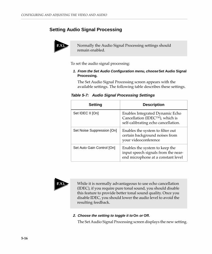
CONFIGURING AND ADJUSTING THE VIDEO AND AUDIO
Setting Audio Signal Processing
To set the audio signal processing:
1. From the Set Audio Configuration menu, choose Set Audio Signal Processing .
The Set Audio Signal Processing screen appears with the available settings. The following table describes these settings.
2. Choose the setting to toggle it to On or Off .
The Set Audio Signal Processing screen displays the new setting.
F Y I F.Y.I. Normally the Audio Signal Processing settings should remain enabled.
Table 5-7: Audio Signal Processing Settings
Setting Description
Set IDEC II [On] Enables Integrated Dynamic Echo Cancellation (IDECª), which is self-calibrating echo cancellation.
Set Noise Suppression [On] Enables the system to Þlter out certain background noises from your videoconference
Set Auto Gain Control [On] Enables the system to keep the input speech signals from the near-end microphone at a constant level
F Y I F.Y.I. While it is normally advantageous to use echo cancellation (IDEC), if you require pure tonal sound, you should disable this feature to provide better tonal sound quality. Once you disable IDEC, you should lower the audio level to avoid the resulting feedback.
5-16

Adjusting System Video Levels
Selecting Initial G.711 FormatTo select the initial G.711 format:
1. From the Set Audio Configuration menu, choose Select Initial G.711 Format .
The G.711 Format screen appears with available settings. The following table describes these settings.
2. Choose a setting from the menu.
The Select Initial G.711 Format menu appears with an [X] next to the setting.
Adjusting System Video Levels
You use the SMPTE (Society for Motion Picture and Television Engineers) color bars test pattern to test and adjust the monitor tint, color, contrast, and brightness. While the color bars are displayed on the screen, a 1-kilohertz (kHz) tone sounds. This tone enables you to test and adjust the system volume.
This section describes how to use the system menus to display the SMPTE color bars and provides procedures to adjust the monitor video level while the SMPTE color bars are displayed.
Table 5-8: Initial G.711 Format Settings
Setting Description
A-law Sets the preferred mode for calling most European countries. To determine if this law applies to your site, ask your telephone service provider.
µ-law Sets the preferred mode for calling in North America. To determine if this law applies to your site, ask your telephone service provider.
5-17

CONFIGURING AND ADJUSTING THE VIDEO AND AUDIO
Displaying the SMPTE Color BarsTo display the SMPTE color bars:
1. Press SETUP.
The Setup menu appears.
2. Choose View Diagnostics Menu .
The Diagnostics menu appears.
3. Choose View Near-End Tests .
The Near-End Tests menu appears.
Near-End Tests
View Previous MenuSelect System Self-TestSystem Self-Test with LoopbackRun Video-Audio Test PatternRun Video-Audio LoopbackRun Local Channel LoopbackRun CSU Self-TestSet Test ConfigurationStop Test
F Y I F.Y.I. The Run CSU Self-Test item only appears when a 4-wire CSU network interface is installed.
5-18

Adjusting System Video Levels
4. Choose Run Video-Audio Test Pattern .
The SMPTE color bars test pattern appears on the screen and a 1-kHz tone is produced.
Figure 5-1: SMPTE Color Bars Test Pattern
5. If the contrast, brightness, color, and tint need adjusting, perform the steps in the next section.
6. To exit from the test, press HANG UP.
Adjusting the VideoWhen you adjust the video on your monitor, you will adjust its contrast, brightness, color, and tint. On a PAL system, you wonÕt need to adjust the tint.
To adjust the tint and color properly, use the blue Þlter slide packaged in the plastic holder on the inside front cover of this guide.
To adjust the video:
1. Display the SMPTE color bars, as described in the previous section.
5-19

CONFIGURING AND ADJUSTING THE VIDEO AND AUDIO
2. Adjust the brightness.
On the bottom right side of the screen, fade out the three thin bars, keeping the third bar slightly visible.
3. Set the contrast to the lowest level that allows for a good picture in the room.
4. If necessary, repeat steps 2 and 3, since one adjustment may affect the other.
Fade out these bars Keep this barslightly visible
5-20

Adjusting System Video Levels
5. Adjust the color.
a. Look through the blue Þlter slide at the two sets of bars on each side of the test pattern.
b. Adjust the color control until the top and bottom bars appear as a single bar.
c. If you have a PAL system, go to step 8.
Bars for color adjustment
Bars for color adjustment
5-21

CONFIGURING AND ADJUSTING THE VIDEO AND AUDIO
6. Adjust the tint.
a. Look through the blue Þlter slide at the two sets of bars on both sides of the center bars in the test pattern.
b. Adjust the tint control until the top and bottom bars appear as a single bar.
7. If necessary, repeat steps 5 and 6, since one adjustment may affect the other.
8. Press HANG UP when you are done adjusting the video.
Adjusting System Audio Levels
This section describes how to test the audio on a system using monitor speakers.
Note: To perform the following two procedures, you need a sound pressure meter.
Bars for tintadjustment
Bars for tintadjustment
F Y I F.Y.I. If the Concorde¥4500 is in a WorldCart with Bose speakers, no audio system calibration is required. Just use the keypad volume controls to adjust the volume to a comfortable level.
5-22

Adjusting System Audio Levels
Testing the AudioTo test the audio on the monitorÕs speakers:
1. Following the procedure on page 5-18, display the SMPTE color bars and sound the 1-kHz tone.
2. Select Run Video-Audio Test Pattern from the Near-End Tests menu.
The 1-kHz test tone is set to its nominal level.
3. To exit from the test, press HANG UP.
Adjusting the AudioTo adjust the volume for your monitorÕs speakers:
1. Position the keypad and all additional microphones where you plan to use them in the conference room.
2. Reset the echo canceler by pressing the main system power switch on the electronics module.
3. Display the SMPTE color bars and sound the 1-kHz tone by using the “Displaying the SMPTE Color Bars” procedure at the beginning of this chapter.
T I P
After you have set the monitor volume control, you should adjust loudness with the keypad volume control and not with the monitor volume control.
5-23

CONFIGURING AND ADJUSTING THE VIDEO AND AUDIO
4. To adjust the audio level using a sound pressure meter:
a. Place the microphone of a sound pressure meter at a location representing a normal listening position.
Make sure that the sound pressure meter is pointing toward the room loudspeakers.
b. Adjust the monitor volume control (or the ampliÞer LEVEL knobs) until the sound pressure meter reads 74 dBSPL.
5. Press HANG UP to terminate the test.
6. Verify the volume setting by running a local channel loopback test from the Near-End Tests menu:
a. Get an acceptable loudness by turning down the keypad volume control immediately.
b. Say Òone, twoÓ a few times, pausing each time.
You should hear Òone, twoÓ repeated over the speaker, but should not hear any following artifacts or squeaks.
T I P
In big rooms, take measurements at important listening positions and set the volume to a level as close to 74 dBSPL as possible at all of the positions.
5-24

Adjusting the Camera
c. Reduce the monitor volume control slightly, as necessary, until you no longer hear any artifacts or squeaks.
d. Adjust the keypad volume control, as necessary, to maintain an acceptable loudness.
7. Place a call as a final verification.
If participants at the far-end site hear an echo, reduce your monitor volume control slightly.
Follow these guidelines:
a. After you have adjusted the monitor volume, do not change the monitor volume setting. Use the keypad volume control, if necessary, to change the volume. The echo canceler then works properly.
b. Do not change the audio tone controls on the monitor. Distortions could result and could affect the performance of the echo canceler.
c. The echo canceler does not handle distortion. Use the keypad volume control and decrease the volume until any distortion is no longer evident.
Adjusting the Camera
You may need to adjust the pan-tilt-zoom (PTZ) camera white balance to room lighting conditions, as well as adjust the focus. Using menu screens, you can make the following adjustments:
❑ White balance to room lighting conditions
❑ Camera focus for full automatic or delayed (timed) automatic operation
❑ Iris opening for normal (automatic), 1 f-stop closed, or 1 f-stop open
F Y I F.Y.I. Because the echo canceler takes a few seconds of speech to adapt to the room acoustics, you may hear an echo at Þrst.
5-25

CONFIGURING AND ADJUSTING THE VIDEO AND AUDIO
You can adjust the following pan-tilt-zoom camera sources at the near-end site:
❑ Main camera
❑ AUX A camera (usually your auxiliary camera)
❑ AUX B camera
When you display the menus, the current mode or status is indicated. When you Þrst install the camera module, all camera modes and options are set to their default settings, as shown in the following table.
Any changes you make to these settings through the menus are saved.
Adjusting the White BalanceUse the procedure in this section to adjust the near-end camera white balance to compensate for current room lighting conditions.
Table 5-10 describes the adjustment modes.
F Y I F.Y.I. You cannot adjust the white balance, focus, or iris settings while in a call.
Table 5-9: Camera Power-Up Default Settings
Mode/Option Default Setting
White balance Auto
Focus Auto
Iris Auto
5-26

Adjusting the Camera
Table 5-10: White Balance Adjustment Modes
This mode... Makes this adjustment... Use it when...
Auto Sets the camera white balance to adjust automatically to changes in the current lighting conditions.
The background in the videoconference room is not a vivid or variegated color. This is the default mode.
One Touch Enables the camera to adjust the white balance to the current lighting conditions.
You want the camera to render the precise color of a product under special lighting conditions. Use only with extreme conditions.
Note: The camera does not retain this setting during system reset (power cycling) but returns to the Auto white balance mode.
Indoor Presets the camera white balance compensation to incandescent lighting conditions (3200o Kelvin lighting color temperature).
You wish to have the camera color rendering shift toward blue.
Note: The recommended lighting color temperature range is from 3200o through 5200o Kelvin. For best results, do not mix ßuorescent and incandescent light sources.
Outdoor Presets the camera white balance compensation to outdoor lighting conditions (5800o Kelvin lighting color temperature).
You wish to have the camera color rendering shift toward red.
5-27
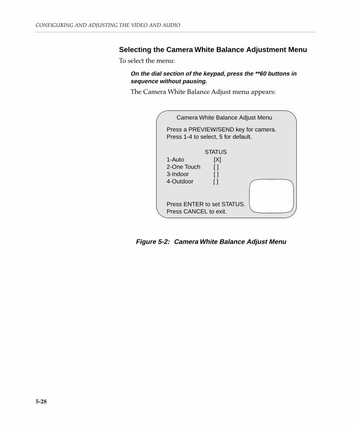
CONFIGURING AND ADJUSTING THE VIDEO AND AUDIO
Selecting the Camera White Balance Adjustment MenuTo select the menu:
On the dial section of the keypad, press the **60 buttons in sequence without pausing.
The Camera White Balance Adjust menu appears:
Figure 5-2: Camera White Balance Adjust Menu
Camera White Balance Adjust Menu
Press a PREVIEW/SEND key for camera.Press 1-4 to select, 5 for default.
STATUS1-Auto [X]2-One Touch [ ]3-Indoor [ ]4-Outdoor [ ]
Press ENTER to set STATUS.Press CANCEL to exit.
5-28

Adjusting the Camera
Selecting a CameraTo adjust a near-end camera:
1. Press one of the following buttons in the SEND or PREVIEW area of your keypad for the near-end (local) camera source you want to adjust:
❑ MAIN camera
❑ AUX A camera
❑ AUX B camera
An [X] on the screen indicates the current camera status for the camera you selected.
❑ If you press the button in the PREVIEW row, the menu appears in the picture-in-picture (PIP) window and the image from the camera source appears on the full screen.
To shift the menu in the PIP to the full screen, press VIEW FAR END.
❑ If you press the button in the SEND row, the menu appears on the full screen and the image from the camera source appears in the PIP.
2. Choose the adjustment mode as described in the following section.
Choosing the Adjustment ModeYou can adjust the camera using any of the following options:
❑ Default setting
❑ Automatic
❑ One touch
❑ Indoor
❑ Outdoor
Referring to Table 5-10, choose an adjustment mode, and follow the instructions in this section.
5-29

CONFIGURING AND ADJUSTING THE VIDEO AND AUDIO
Default Setting
To adjust your camera using the default setting:
Press 5 on the keypad.
The white balance status for the camera you chose is automatically set to the default setting Auto as described in Table 5-10.
To make another adjustment:
Choose another camera source, and adjust the white balance, if necessary.
To exit the adjustment mode:
Press CANCEL.
The following message appears on the monitor when no video call is present:
Automatic Mode
To adjust your camera using the automatic mode:
1. Press 1 on the keypad.
2. Press ENTER.
The camera automatically adjusts the white balance to existing room lighting conditions.
The [X] remains in the STATUS column of the Camera White Balance Adjust menu.
F Y I F.Y.I. The screen shows the current status for the camera you selected.
PictureTel Ready
5-30

Adjusting the Camera
One Touch Mode
To adjust your camera using the one touch mode:
1. Press 2 on the keypad.
The One Touch Mode screen appears:
Figure 5-3: One Touch Mode Screen
2. Hold a sheet of white paper or a white surface in front of the camera.
3. Press the zoom-in button until the paper fills the entire screen display.
4. Wait 15 seconds to give the camera time to complete adjusting automatically to the white surface.
To save the new white balance adjustment:
Press ENTER.
The Camera White Balance Adjust menu appears on the full screen with an [X] in the STATUS column.
To cancel the mode setting:
Press CANCEL.
The Camera White Balance Adjust menu appears.
One Touch Mode Screen
Point the camera at a white background.Press ZOOM IN.Press ENTER when ready.
Press CANCEL to exit.
***Mode is reset to Auto on power up.
5-31

CONFIGURING AND ADJUSTING THE VIDEO AND AUDIO
Indoor Mode
To adjust your camera using the indoor mode:
1. Press 3 on the keypad.
2. Press ENTER.
The camera automatically adjusts the white balance for indoor lighting conditions.
An [X] appears in the STATUS column on the Camera White Balance Adjust menu.
Outdoor Mode
To adjust your camera using the outdoor mode:
1. Press 4 on the keypad.
2. Press ENTER.
The camera automatically adjusts the white balance for outdoor lighting conditions.
An [X] appears in the STATUS column on the Camera White Balance Adjust menu.
5-32

Adjusting the Camera
Adjusting the Focus and Iris SettingsUse the procedure in this section to adjust the focus and iris settings for the pan-tilt-zoom camera.
The following table describes the adjustment settings.
Table 5-11: Focus and Iris Adjustment Settings
This option... Makes this adjustment... Use it when...
Gain Even though a choice for Gain appears on the menu, you cannot adjust gain. Gain is automatically set for the pan-tilt-zoom cameras to operate in typical lighting conditions, such as exist in most business ofÞces.
If you select Gain, ? appears brießy in the STATUS column. However, the camera makes no changes.
Focus Auto Sets the camera to focus continuously.
Use this setting most of the time.
Delay Focuses the camera automatically for four seconds; then sets the camera for the appropriate focus.
You expect videoconference participants to move about within the camera Þeld of view, particularly when these participants do not move substantially closer to or away from the camera.a Thus the camera does not seek a new focus, and the transmitted image quality is extremely sharp and stable.
Note: If you press the keypad arrow buttons, it will cause the camera to refocus.
5-33

CONFIGURING AND ADJUSTING THE VIDEO AND AUDIO
a. Under typical office lighting conditions, the camera depth of focus (depth of field) is within adistance of approximately two feet closer than and four feet further than the focus point.
Iris Auto Sets the camera iris at the factory-set calibration.
Your videoconference occurs in typical ofÞce lighting conditions.
Close Sets the camera at 1 f-stop darker.
You need to compensate for an overly bright picture.
Open Sets the camera at 1 f-stop brighter.
You need to compensate for a dark subject, which can occur in a backlighted situation.
Manual Enables you to darken or brighten the image in small steps. Use the arrow buttons to make manual adjustments.
After you use the arrow buttons, you do not press ENTER.
You want to adjust the iris manually.
Table 5-11: Focus and Iris Adjustment Settings (Continued)
This option... Makes this adjustment... Use it when...
5-34

Adjusting the Camera
Selecting the Gain, Focus, and Iris Adjustment MenuTo select the menu:
Press the **61 buttons on the keypad in sequence without pausing.
The Gain, Focus, and Iris Adjust menu appears:
Figure 5-4: Gain, Focus, and Iris Adjust Menu
To adjust a near-end camera:
Press one of the following keypad buttons in the SEND or PREVIEW row for the near-end (local) camera source you want to adjust:
❑ MAIN camera
❑ AUX A camera
❑ AUX B camera
If you press the button in the PREVIEW row, the menu appears in the PIP and the image from the camera source appears on the full screen. To shift the menu in the PIP to the full screen, press VIEW FAR END.
If you press the button in the SEND row, the menu appears on the full screen and the image from the camera source appears in the PIP.
Gain, Focus, and Iris Adjust Menu
CMD STATUS1-Gain (Normal/Up) [ ] [ ]2-Focus (Auto/Delay) [ ] [ ]3-Iris (Auto/Close/Open [ ] [ ]
Press a PREVIEW/SEND key for a camera.Press 1-3 to select option, 5 for default.Press again to select CMD.Press ENTER to set STATUS.Press CANCEL to exit.
5-35

CONFIGURING AND ADJUSTING THE VIDEO AND AUDIO
Choosing the Setting to AdjustYou can adjust the follow settings on the camera:
❑ Focus
❑ Iris
Referring to Table 5-11, choose one of the settings, and follow the instructions in this section.
Adjusting the Focus
You can adjust the focus on your camera using either the automatic or the delayed setting.
Here are several guidelines to remember when using the delayed focus setting:
❑ If you press an arrow button to pan or tilt the camera, the camera automatically focuses. The camera continues to focus automatically for four seconds and then locks itself at the appropriate focus.
❑ If you press the zoom in or out button, the camera repeats the delay cycle by focusing automatically for four seconds and then returning to manual focus.
To adjust the focus on your camera:
1. Press 2 on the keypad.
The Gain, Focus, and Iris Adjust menu appears with the following settings:
2. Press 2 again to change the focus command.
In the CMD column, A toggles to D.
3. Press ENTER.
A ? appears brießy in the STATUS column, and then the new focus status (A or D) appears.
The Gain, Focus, and Iris Adjust menu remains on the screen.
1 - Gain (Normal/Up)2 - Focus (Auto/Delay)3 - Iris (Auto/Close/Open)
STATUS[ ][A][ ]
[ ][A or D]
[ ]
CMD
5-36

Adjusting the Camera
Adjusting the Iris
To adjust the iris setting on your camera:
1. Press 3 on the keypad.
The Gain, Focus, and Iris Adjust menu appears as follows:
2. Press 3 until you cycle the CMD column to the adjustment you wish:
❑ A for Auto
❑ C for Close
❑ O for Open
To select M for Manual adjustments, press the or arrow button on the keypad.
The M appears in the CMD column.
To save the new camera adjustment:
Press ENTER.
A ? appears brießy in the STATUS column, and then the new iris setting status (A, C, O, or M) appears.
The Gain, Focus, and Iris Adjust menu remains on the screen.
1 - Gain (Normal/Up)2 - Focus (Auto/Delay)3 - Iris (Auto/Close/Open)
STATUS[ ][ ][A]
[ ][ ]
[A, C, or O]
CMD
5-37

CONFIGURING AND ADJUSTING THE VIDEO AND AUDIO
To adjust the iris opening manually:
The Gain, Focus, and Iris Adjust menu appears with the following settings:
Press or on the keypad to adjust the iris opening.
The ∧ or ∨ arrow may appear brießy in the STATUS column, depending on which arrow button you are pressing. When you stop pressing the arrow button, an M appears in the STATUS column.
To exit the adjustment mode:
Press CANCEL.
The PictureTel Ready message appears when no video call is present.
Using the Default Setting
To adjust the iris setting to the default setting:
Press 5 on the keypad.
The camera status is automatically reset to the default setting Auto, as described in Table 5-11.
The PictureTel Ready message appears.
1 - Gain (Normal/Up)2 - Focus (Auto/Delay)3 - Iris (Auto/Close/Open)
STATUS[ ][ ]
[M]
[ ][ ]
[M]
CMD
T I P
Do not press ENTER after you press the arrow button.
5-38

ConÞguring Ports

This chapter describes how to
❑ Set the control ports
❑ Set the data ports

6
ConÞguring PortsThe Concorde¥4500 provides two control ports (A and B) that pass status and control information and four data ports (A, B, C, and D) that communicate with external devices, such as dataconferencing devices, PCs, and modems. This chapter explains how to conÞgure these ports.
When you choose Set Data Port Configuration from the ConÞguration menu, the Set Data Port ConÞguration menu appears:
Set Data Port Configuration
View Previous MenuSet Control Port A [Control Protocol]Set Control Port B [Disabled]Set Data Port A [Disabled]Set Data Port B [Disabled]Set Data Port C [Disabled]Set Data Port D [Disabled]
F Y I F.Y.I. The data ports are listed only if a Data Interface board is present.
6-1

CONFIGURING PORTS
Setting Control Port A
You can use Control Port A to pass status and control information.
The following table lists the options when you choose Set Control Port A from the Set Data Port ConÞguration menu.
The following table lists the Control Port A type settings.
F Y I F.Y.I. The conÞguration of Control Port A determines the list of options.
Table 6-1: Set Control Port A Screen Options
Option Description
Select Type ConÞgures the mode of operation for the control port, as described in Table 6-2.
Enter Baud Rate ConÞgures the rate at which information passes through the control port.
The Control Protocol port type has a default setting of 1200.
Select Parity Determines the number of data bits in each word of information that passes through the control port as well as the parity checking of a received word:
❑ 8 bits, None
❑ 8 bits, Odd (default)
❑ 8 bits, Even
Table 6-2: Control Port A Type Settings
Setting Definition
Disabled Disables Control Port A
6-2

Setting Control Port B
To change the Control Port A settings:
1. From the Configuration menu, choose Set Data Port Configuration .
The Set Data Port ConÞguration menu appears.
2. Choose Set Control Port A .
3. Choose a selection from the menu.
A selection menu for Type or Parity or a box to enter a new Baud Rate appears.
4. Choose a new setting or enter a baud rate.
The Set Control Port A ConÞguration screen appears with the new setting or rate.
Setting Control Port B
You can use Control Port B to pass data, for example, between your PC and a PC at another videoconferencing site. In addition, you can use the system network manager program to send and receive control protocol messages through Control Port B.
Table 6-3 lists the options when you choose Set Control Port B from the Set Data Port ConÞguration menu.
Control Protocol
(default)Used to send and receive control protocol messages, which can be status and/or diagnostic information from a far-end site or from a near-end device, such as a PC.
Table 6-2: Control Port A Type Settings (Continued)
Setting Definition
F Y I F.Y.I. The conÞguration of Control Port B determines the list of options on the screen.
6-3

CONFIGURING PORTS
Table 6-3: Set Control Port B Screen Options
Option Description
Select Type ConÞgures the mode of operation for the control port, as described in Table 6-4.
Enter Baud Rate ConÞgures the rate at which information passes through the control port:
❑ The Network Manager port type has a default setting of 1200.
❑ Dataconferencing application ports have a default setting of 19200.
Select Parity Determines the number of data bits in each word of information that passes through the control port as well as the parity checking of a received word:
❑ 8 bits, None (default)
❑ 8 bits, Odd
❑ 8 bits, Even
❑ 7 bits, None
❑ 7 bits, Even
This option can be set for Network Managers and asynchronous devices.
Select RTS/DTR (Request to Send/Data Terminal Ready) ConÞgures the hardware ßow control exerted by the system:
❑ Ignored, used when your terminal device does not observe the RTS/DTR ßow control protocol.
❑ Not Ignored, used when your terminal device observes the RTS/DTR ßow control protocol.
This option can be set for asynchronous devices.
6-4

Setting Control Port B
The following table lists the Control Port B settings.
Select XON/XOFF (Transmit on/Transmit off)ConÞgures the software ßow control method, deÞned by the American Standard Code for Information Interchange (ASCII):
❑ Enabled, used when this method is required by the terminal device to stop and start the ßow of data.
❑ Disabled, used when this method is not used by the terminal device.
This option can be set for asynchronous devices.
Table 6-3: Set Control Port B Screen Options (Continued)
Option Description
Table 6-4: Control Port B Type Settings
Setting Definition
Disabled (default) Disables control port B
Asynchronous ConÞgures the port for asynchronous operation
Network Manager ConÞgures the system when you are using a network manager to control the system
GroupShare ConÞgures the port to communicate with the optional GroupShareª applications. This selection is not listed if GroupShare is set on another data port.
Note: PictureTel recommends that you conÞgure GroupShare on Data Port A.
GroupView 1.0 ConÞgures the port to communicate with the PictureTel GroupViewª document conferencing projector. This selection is not listed if GroupView 1.0 is set on another data port.
Note: PictureTel recommends that you conÞgure GroupView 1.0 on Data Port B.
6-5

CONFIGURING PORTS
To change the Control Port B settings:
1. From the Configuration menu, choose Set Data Port Configuration.
The Set Data Port ConÞguration menu appears.
2. Choose Set Control Port B .
3. Choose a selection from the menu.
Either a selection menu for Type, Parity, RTS/DTR, and XON/XOFF appears, or a box to enter a new Baud Rate appears.
4. Choose a new setting or enter a baud rate.
The Set Control Port B ConÞguration screen appears with the new setting or rate.
Setting Data Port A, B, C, or D
You can use a data port to communicate with an external communication or computing device, such as a modem or a PC.
The Data Interface board with the Concorde¥4500 has four data ports. Data Ports A and B are RS-232 serial ports. Data Ports C and D can be any of the following pairs:
❑ RS-232
❑ RS-449
❑ V.35
F Y I F.Y.I. PictureTel recommends the following:
❑ For GroupShare applications, the recommended port is Data Port A.
❑ For GroupView 1.0, the recommended port is Data Port B.
6-6

Setting Data Port A, B, C, or D
You can conÞgure each data port for either asynchronous or synchronous communication. These ports then operate at the following speeds in kilobits per second:
To conÞgure a data port:
1. Choose Set Data Port A , B, C, or D from the Set Data Port Configuration menu.
2. Choose an option.
Table 6-5 lists the options.
Port Type
Asynchronous Synchronous
RS-232 0.3 through 38.4 kbps 0.3 through 19.2 kbps
RS-449 0.3 through 38.4 kbps 0.3 through 64.0 kbps
V.35 0.3 through 38.4 kbps 0.3 through 64.0 kbps
F Y I F.Y.I. The GroupShare, GroupView 1.0, GroupView 2.0, GroupBoard, MultiBoard, and LiveShare Plus 4.0 ports operate at the asynchronous port speeds.
T I P
When you connect a device to a data port, you must conÞgure that port as required by the device.
For example, when you connect a PC to your system to perform data sharing, you must conÞgure the port as required by the PC.
6-7

CONFIGURING PORTS
If you choose Synchronous under H.320 and your system is conÞgured for an incompatible audio transmission format, you are given the option to reset it to Automatic. If you do not reset the audio transmission format, the port conÞguration and audio transmission format are not set to Synchronous.
3. Choose a new setting or enter a baud rate.
The Set Data Port A, B, C, or D screen appears with the new setting.
F Y I F.Y.I. Your system conÞguration determines which options appear in the Set Data Ports screen.
6-8

Setting Data Port A, B, C, or D
Table 6-5: Set Data Ports Screen Options
Menu Option Description
Select Type ConÞgures the mode of operation for the data port:
❑ Disabled (default)
❑ Asynchronous
❑ Synchronous. Data Ports A and B support H.320 and Data Ports A, B, C, and D support SG3.
Under H.320, Synchronous supports the following audio formats: Automatic, PT716plus, PT.724, and G.728.
You can use synchronous data simultaneously with T.120 or asynchronous data. However, you can only conÞgure one port to Synchronous at a time.
❑ GroupView 1.0. Select this option if you are connecting a T.120 dataconferencing device to your data port and the far-end videoconferencing system is one of the following:
❑ Concorde¥4500 6.11 or lower
❑ Venue¥2000 1.21 or lower
❑ SwiftSite 1.01 or lower
This selection is not listed if GroupView 1.0 is set on another data port.
6-9

CONFIGURING PORTS
❑ GroupView 2.0. Select this option if you are connecting a GroupView to your data port and the far-end videoconferencing system is one of the following:
❑ Concorde¥4500 6.12 or higher
❑ Venue¥2000 1.3 or higher
❑ SwiftSite 1.3 or higher
Otherwise, use GroupView 1.0.
GroupView 2.0 is not listed if it is set on another data port.
❑ GroupBoard. Select this option if you are connecting a GroupBoard to your data port and the far-end videoconferencing system is one of the following:
❑ Concorde¥4500 6.12 or higher
❑ Venue¥2000 1.3 or higher
❑ SwiftSite 1.3 or higher
Otherwise, use GroupView 1.0.
GroupBoard is not listed if it is set on another data port.
❑ LiveShare Plus 4.0. Select this option if you are connecting LiveShare Plus 4.0 to your data port and the far-end videoconferencing system is one of the following:
❑ Concorde¥4500 6.12 or higher
❑ Venue¥2000 1.3 or higher
❑ SwiftSite 1.3 or higher
Otherwise, use GroupView 1.0.
LiveShare Plus 4.0 is not listed it is set on another data port.
Table 6-5: Set Data Ports Screen Options (Continued)
Menu Option Description
6-10

Setting Data Port A, B, C, or D
❑ MultiBoard. Select this option if you are connecting a MultiBoard to your data port and the far-end videoconferencing system is one of the following:
❑ Concorde¥4500 6.12 or higher
❑ Venue¥2000 1.3 or higher
❑ SwiftSite 1.3 or higher
Otherwise, use GroupView 1.0.
MultiBoard is not listed if it is set on another data port.
❑ Other Peripheral. Select this option if you are connecting a third-party device or dataconferencing device to your data port.
Enter Baud Rate ConÞgures the rate at which information passes through a data port.
For dataconferencing applications, the default baud rate is 19.2 kbps.
Select Parity Determines the number of data bits in each word of information that passes through a data port, as well as the parity checking of a received word:
❑ 8 bits, None (default)
❑ 8 bits, Odd
❑ 8 bits, Even
❑ 7 bits, None
❑ 7 bits, Even
You can set this option for asynchronous and synchronous devices.
Table 6-5: Set Data Ports Screen Options (Continued)
Menu Option Description
6-11

CONFIGURING PORTS
Select RTS/DTR ConÞgures the hardware ßow control exerted by the system:
❑ Ignored, used when your terminal device does not observe the RTS/DTR ßow control protocol
❑ Not Ignored, used when your terminal device observes the RTS/DTR ßow control protocol.
You can set this option for asynchronous and synchronous devices.
Select XON/XOFF (Transmit on/Transmit off)ConÞgures the software ßow control method, deÞned by the American Standard Code for Information Interchange (ASCII):
❑ Enabled, used when this method is required by the terminal device to stop and start the ßow of data.
❑ Disabled, used when this method is not used by the terminal device.
You can set this option for asynchronous devices on Data Ports A and B. If Data Ports C and D are RS-449 or V.35 ports, you can set this option for synchronous devices.
Table 6-5: Set Data Ports Screen Options (Continued)
Menu Option Description
6-12

ObtainingDiagnostic
Information

This chapter describes how to
❑ View the System ConÞguration screen
❑ View near-end status
❑ Run near-end tests
❑ Run far-end tests
❑ Set up remote diagnostics
❑ View the Call Log

7
ObtainingDiagnosticInformation
This chapter describes how to obtain system diagnostic information by:
❑ Viewing the System ConÞguration screen
❑ Viewing current system statistics
❑ Running tests for the near end and the far end to determine system performance
❑ Using the remote diagnostics option to have the results of system tests sent to a PictureTel location for analysis
❑ Viewing the Call Log
You may also refer to the Concorde¥4500 Servicing Guide for more troubleshooting and diagnostic information.
7-1

OBTAINING DIAGNOSTIC INFORMATION
Viewing the System Configuration
When you choose View System Configuration from the Setup menu, the System ConÞguration screen appears:
The System ConÞguration screen provides important conÞguration information about the Concorde¥4500. This information can help a PictureTel service provider isolate a problem.
System Configuration
Network Interface: [Dialed]Two-line dialing: [Delayed]Video Answer Mode: [Automatic]Audio Answer Mode: [Automatic]Control A: [Control Protocol]Control B: [Disabled]Data A: [Disabled]Data B: [Disabled]Data C: [Disabled]Data D: [Disabled]Video Send Format: [Automatic]Audio Send Format: [Automatic]IDEC [On] NS [On] AGC [On]
F Y I F.Y.I. The data ports are listed only if a Data Interface board is present.
7-2

Using the Diagnostics Menus
Using the Diagnostics Menus
When you choose View Diagnostics Menu from the Setup menu, the Diagnostics menu appears:
Diagnostics Menu
View Previous MenuView Near-End StatusView Near-End TestsView Far-End TestsView In-Call Loopback TestsEnter Remote Diagnostic Mode
See near-end statistics, monitor the CSU, and clear network statistics and fault codes
Run diagnostic tests to eliminate near-end problems
Run diagnostic tests to eliminate far-end problems
Allow a PictureTel service provider to run diagnostic tests on your system
Allow field service personnel to run board-level and other diagnostic tests
7-3

OBTAINING DIAGNOSTIC INFORMATION
rd
Viewing Near-End StatusWhen you choose View Near-End Status from the Diagnostics menu, you can choose from the selections in the following table:
a. This item appears only when your system has an internal four-wire CSU network interface boainstalled.
Table 7-1: Near-End Status Menu Options
Menu Option Definition
View Network Statistics Displays the current channel statistics.
Refer to Table 7-2 for SG3 and to Table 7-3 for SG4, H.261, and H.263.
View Call Parameters Lists the video transmission modes and frame rates (frames per second) for the sending and the receiving sites.
Refer to Table 7-4.
View Last Ten Fault Codes Displays the last 10 fault codes.
Refer to Table 7-5.
View Software Version Displays the system software version and lists the customer-ordered options that are included on the software cartridge.
Refer to Table 7-6.
Monitor CSUa Displays the signals and status messages from both near-end CSU channels.
Refer to Table 7-7 and Table 7-8.
Clear Network Statistics Resets the channel statistics counters to zero.
Clear Fault Codes Clears the fault code list.
7-4

Using the Diagnostics Menus
The following table describes the current network channel statistics for SG3 communications.
Table 7-2: SG3 Network Statistics
Statistic Description Interpretation
Checksum Errors The sum of video errors that were not caused by an error in the channels
A large number of errors indicates a faulty transmitting AP board at the far-end site or a faulty receiving AP board at the near-end site.
After the call, place the systems at each site in local channel loopback mode. The system with the checksum errors has the faulty board.
Packet Dropouts The number of packets with errors that were discarded because they included an uncorrectable error or could not be decoded
High numbers indicate a transmission line problem or, less frequently, a CSU problem. If your system uses an external CSU, the cabling to the CSU may be faulty.Verify the numbers by running a near-end local channel loopback test.
Packet Errors The sum of the uncorrected packets for all active channels
Refer to the interpretation for Uncorrected Packets.
Error Free Packets The number of packets received from the far end by each channel without error
This indicates that the transmission line and the CSUs are valid.
Corrected Packets The number of packets with errors that were received from the far end by each channel and were corrected by the error-correction software
Small numbers for this statistic are expected during normal operation.
High numbers indicate a transmission line problem or, less frequently, a CSU problem. If your system uses an external CSU, the cabling to the CSU may be faulty.Verify the numbers by running a near-end local channel loopback test.
7-5

OBTAINING DIAGNOSTIC INFORMATION
Uncorrected Packets The number of packets with errors that were received by each channel but were not corrected
High numbers indicate a transmission line problem or, less frequently, a CSU problem. If your system uses an external CSU, the cabling to the CSU may be faulty.Verify the numbers by running a near-end local channel loopback test.
TX clock Transmit clock This number indicates the transmit data rate.
RX clock Receive clock This number indicates the receive data rate.
Modem Signals with an internal CSU board
The signals are:
CTS Clear to send
DTR Data terminal ready
RR Receive ready
RTS Request to send
Table 7-2: SG3 Network Statistics (Continued)
Statistic Description Interpretation
7-6

Using the Diagnostics Menus
The following table describes the current network channel statistics for SG4, H.261, and H.263 communications.
Table 7-3: SG4 and H.320 Network Statistics
Statistic Description Interpretation
Channel Use Initial for channel 12nd ch for channel 2
This line indicates the logical channel number that is being transmitted or received on the individual ports.
Tx Clock Transmit clock This number indicates the transmit data rate.
Rx Clock Receive clock This number indicates the receive data rate.
Chans - Tx/Rx The transfer rate This number should correspond to the Tx or Rx Clock rates:
1B = 64000 1Br = 56000
1H0 = 3840001H0r = 336000
Tx Frames The number of H.221 frames transmitted
This count continually increments during an SG4 or H.261 call or while an SG4 or H.261 call is being attempted.
Rx Frames The number of H.221 frames received
This count continually increments during an SG4 or H.261 call or while an SG4 or H.261 call is being attempted.
Rcv Err Bit The number of H.221 error bits received from the far-end system
The far-end system has indicated a problem in the data it is receiving. This statistic represents an end-to-end quality monitoring feature.
Alignment Lost The number of times the SG4 or H.261 frame alignment signal has not been received as expected
Usually this count, which indicates the integrity of the end-to-end connection, increments by one at the end of a call or when a far-end loopback test is initiated.
Any other change in this counter indicates a failure of the transmission line or, less frequently, a CSU problem.
7-7

OBTAINING DIAGNOSTIC INFORMATION
Vid Fs Total The total number of video frames received
This number indicates that video is being received.
Fixed The number of video frames received with a correctable error
A high number may indicate a transmission line problem.
Verify by checking the Alignment Lost count.
Also, refer to the BAS Er statistic.
UnFixed The number of video frames received with an error that could not be corrected
A high number may indicate a transmission line problem.
Verify by checking the Alignment Lost count and by checking that the Tx and Rx clocks agree with the Chans - Tx/Rx numbers.
Also, refer to the BAS Er statistic.
BAS Er The number of unrecognized command or capability codes (BAS codes) received from the far-end system
This number may indicate that the far-end system is sending commands or capabilities that the near-end system does not recognize.
It may also mean that there is a transmission line problem, especially when coupled with high numbers of Þxed and unÞxed video frames or alignment losses.
High numbers may be normal when you are communicating with products from other manufacturers.
Checksum Errors The sum of video errors that were not caused by an error in the channels
A large number of errors indicates a faulty transmitting AP board at the far-end site or a faulty receiving AP board at the near-end site.
After the call, place the systems at each site in local channel loopback mode. The system with the checksum errors has the faulty board.
Table 7-3: SG4 and H.320 Network Statistics (Continued)
Statistic Description Interpretation
7-8

Using the Diagnostics Menus
The following table describes the call parameters for the modes and rates of the sending and receiving sites.
Table 7-4: Call Parameters
Mode/RateTransmit/Receive
ParameterDescription
Audio Mode PT724 The audio coding currently in use
G.728
G.722
G.711U
G.711A
SG3
OFF
PT716plus
Audio Rate Framed Either type when Audio Mode is G.711A _law or G.711µ_law
Unframed
16K The rate when Audio Mode is G.728 or PT716plusa
24K The rate when Audio Mode is PT724, G.721, or PT716plusa
32K The rate when Audio Mode is PT716plusa
48K The rate when Audio Mode is G.722
56K
Variable The rate when Audio Mode is SG3.
7-9

OBTAINING DIAGNOSTIC INFORMATION
Video Mode H. 261 CIF - 30 fpsb Common Intermediate Format (CIF) at a frame rate of 30 frames per second for H.261 communications
H.261 QCIF - 30 fpsb Quarter CIF (QCIF) at a frame rate of 30 frames per second for H.261 communications
H.263 CIF - 15 fps Common Intermediate Format (CIF) at a frame rate of 15 frames per second for H.263 communications
H.263 QCIF - 15 fps Quarter CIF (QCIF) at a frame rate of 15 frames per second for H.263 communications
SG3 or SG4 PictureTel proprietary format
LSD Mode None The listing when the system is not currently processing low-speed data (LSD)
PTEL LL The PictureTel proprietary link layer protocol, which enables the data interface and far-end camera control protocols
H.224 H.224 protocol currently in use
Table 7-4: Call Parameters (Continued)
Mode/RateTransmit/Receive
ParameterDescription
7-10

Using the Diagnostics Menus
a. PT716plus can operate at 16K, 24K, or 32K depending on the available bandwidth and the capability of the systemb. To transmit video at 30 frames per second, a system must have two HAP boards and be configured to transmit at 30 fps
MLP Rate 300 The low-speed data rate currently in use
1200
4800
6400
8000
9600
14400
16k
24k
32k
40k
48k
56k
62.4k
OFF
Table 7-4: Call Parameters (Continued)
Mode/RateTransmit/Receive
ParameterDescription
7-11

OBTAINING DIAGNOSTIC INFORMATION
The following table describes the system fault codes.
Table 7-5: System Fault Codes
Fault Code Description
0000 through 3FFF Communications board
4000 through 4FFF Dual board failure. The last two digits in the fault code indicate the failing boards:
8 = HAP49 = HAP8B = VideoC = GDCD = Audio
5000 through 5FFF Software cartridge/Backplane
6000 through 6FFF Communications board
7000 through 7FFF Data Interface board
8000 through 8FFF Array Processor board
9000 through 9FFF Array Processor board
A000 through AFFF Array Processor board
B000 through BFFF Video board
C000 through CFFF Graphics Daughter board
D000 through DFFF Audio board
FFFF Software change
7-12

Using the Diagnostics Menus
The following table describes the system options.
Table 7-6: System Options
Code Description
A Far-end camera control
B Camera presets
C SG3
D VCR
E MCU keypad
F 30 fps
G Multipoint
J Low-end near-end camera control
L Encryption, which also requires an encryption chip
P Picture-in-picture (PIP)
R VGI (graphics)
S 768 kbps
T SG4
V Integrated Dynamic Echo Cancellation (IDEC II)
W Noise suppression/automatic gain control (NS/AGC)
X G.728
Y PT724
Z Information sharing
7-13

OBTAINING DIAGNOSTIC INFORMATION
The following table describes the CSU signals.
The following table describes the CSU messages.
Table 7-7: CSU Signals
SIgnal Description
CTS Clear to send
DTR Data terminal ready
RR Receive ready
RTS Request to send
Table 7-8: CSU Messages a
Message Description
Command Prompt
Normal messages indicating that the channel is valid
Offline
Online
Line loopback Normal messages indicating that the far-end site has initiated a test
Remote line test
Network loopback A normal message indicating that the network is performing a test
No network signal An error message indicating one of the following:
❑ The network cable is not connected properly between the network wall socket and the PSDN socket on the back of the electronics module.
❑ The digital phone lines are not functioning properly.
Out of Svc/Frame An error message indicating that the network is temporarily out of service
7-14

Using the Diagnostics Menus
rr
Running Near-End Tests
a. The last six or seven messages for a channel scroll in a circulaframe. The latest message appears on the bottom of the list aftethe prompt (>) symbol.
When you choose View Near-End Tests from the Diagnostics menu, you can choose from the selections in the following table:
Illegal command Messages that may be displayed but do not indicate service is affected in any way
Initialize
No wink
Null msg
Off hook
Table 7-8: CSU Messages a (Continued)
Message Description
Table 7-9: Near-End Tests Menu Options
Menu Option Definition
Select System Self-Test Initiates board-level and additional diagnostics tests.
Refer to page 7-16.
System Self-Test with Loopback
Initiates board-level and additional diagnostics tests.
Refer to page 7-19.
Run Video-Audio Test Pattern Displays the color bars pattern and produces a 1-kHz tone.
Refer to page 7-19.
Run Video-Audio Loopback Displays digitized (but not compressed) near-end video image and audio.
Refer to page 7-19.
7-15

OBTAINING DIAGNOSTIC INFORMATION
rd
a. This item appears only when your system has an internal CSU daughter boainstalled.Running System Self-Tests
Note: If you donÕt know which slot a board is in, you can see the slot number for each board listed next to the board name when the power-up diagnostics run.
To run the diagnostics tests:
1. From the Diagnostics menu, choose View Near-End Tests .
2. Choose Select System Self-Test .
The results from the last self-test appear.
3. Press ENTER.
The start screen appears.
Run Local Channel Loopback Displays digitized (compressed and decompressed) near-end video image and audio.
Refer to page 7-21.
Run CSU Self-Testa When you have a CSU, this test takes the CSU off-line and runs a self-test.
Refer to page 7-22.
Set Test Configuration Allows you to change the channel and data rate conÞguration for the local channel loopback test. The default channel setting is 2 and the default baud rate is 56 kbps.
Refer to page 7-22.
Stop Test Halts the test in progress, and displays the Near-End Tests menu.
Table 7-9: Near-End Tests Menu Options
7-16

Using the Diagnostics Menus
4. Choose YES.
This message appears:
5. Do one of the following:
❑ If you want to test all slots, select YES.
The following message appears:
❑ If you want to test speciÞc slots, select NO.
The following message appears:
Enter the numbers for the slots you want to test, and press ENTER.
The following message appears:
Enter the numbers for the slots you want to test, and press ENTER.
The following message appears:
Test all slots? NO/YES
How many passes?
Which slots? (slots 0 - 9)
Enter digits for slots 0 - 9Example: 245 is slots 2, 4, and 5
Which slots? (slots 10 - 15)
Enter digits for slots 10 - 15Example: 245 is slots 12, 14, and 15
How many passes?
7-17

OBTAINING DIAGNOSTIC INFORMATION
6. Enter the number of passes you want to run, and press ENTER.
The following message appears:
7. Do one of the following:
❑ Choose Yes if you want to reboot and continue with the system self-test. The results from the self-tests appear.
While the tests are running, verify that the software PROM versions for the camera module and for the system software are compatible. Also verify that all board and daughter board versions are compatible and appropriate for your system.
The following message appears brießy when the tests are completed:
Ð If any test fails, FAIL TEST nnn appears while the tests are running.
Ð If any boards fail the system test, order a replacement for the failing board from your PictureTel distributor. Installation instructions are packaged with the new board.
Ð If all tests are successful, the system reboots, and PictureTel Ready appears.
❑ Choose No if you do not want the system to reboot. The system remains operational.
Continue (reboot)? Yes/No
System initialization in progress
F Y I F.Y.I. If you have questions, you can call your PictureTel service provider.
7-18

Using the Diagnostics Menus
Running System Self-Test with LoopbackTo use this feature, you need special hardware loopback connectors.
If you have the loopback connectors, see the Running the System Self-Test with Loopback document that came with the package to run the test.
Running Video-Audio Test Pattern
To use the color bars and tone:
1. From the Diagnostics menu, choose View Near-End Test.
2. Choose Run Video-Audio Test Pattern .
The 1-kHz test tone is set to its nominal level.
3. Refer to Chapter 5 for procedures to adjust the video and audio levels.
Echo and Tunneling EffectsYou may occasionally hear an echo or tunneling effects, especially when parties at different sites speak at the same time. To Þx the echo, tell the far-end party to decrease the monitor volume and increase the keypad volume. To Þx the tunneling, tell the far-end party to increase the monitor volume and decrease the keypad volume.
The echo canceler cannot cancel loudspeaker distortion. If you hear distortion, turn down your keypad volume control.
Running Video-Audio LoopbackWhen you choose Run Video-Audio Loopback from the Near-End Tests menu, your systemÕs analog video and audio signals are displayed
F Y I F.Y.I. If you have any questions, you can call your PictureTel service provider.
F Y I F.Y.I. The keypad volume and mute buttons are disabled during this test.
7-19

OBTAINING DIAGNOSTIC INFORMATION
and sounded on your system. These signals are local to your system and are not digitized, compressed, or sent on telephone lines.
The audio is real time with no delay from speaking to broadcast. This test veriÞes the operation of the near-end components and the cables up to the codec. Thus, if this test runs without errors, your hardware components, such as cameras and peripheral equipment, are probably operating correctly and the problem is elsewhere.
To test the near-end interface electronics:
1. From the Diagnostics menu, choose View Near-End Tests .
2. Choose Run Video-Audio Loopback .
3. Make sure that the image appearing on the full screen is identical with the PIP image.
4. Tap gently on the PowerMic rather than speaking into it.
If the images donÕt match or you canÕt hear sound, continue with the next step.
5. Verify that all cable connections are correct and are securely in place.
If the images donÕt match or you canÕt hear sound, continue with the next step.
F Y I F.Y.I. The VCR audio input to the videoconferencing system is looped back to the VCR audio output. This means that you will not hear the VCR audio at the loudspeaker.
F Y I F.Y.I. You can also test graphic data with a video-audio loopback when the system is conÞgured to display graphic data.
F Y I F.Y.I. The keypad volume and mute buttons are disabled during this test.
7-20

Using the Diagnostics Menus
6. Run the user selectable diagnostics on the Video and Audio boards.
7. Replace the Video or Audio board, if indicated.
Running Local Channel LoopbackTo test your electronics module:
1. From the Diagnostics menu, choose View Near-End Tests .
2. Choose Run Local Channel Loopback .
The video image from your camera source appears after being compressed and decompressed. You hear audio after a half-second delay. The loopback takes place on the daughter board on the Communications board.
If your system has the encryption option installed and enabled, both encryption and decryption occur.
3. Make sure that the image from your camera source appears on the full screen.
The Near-End Tests menu appears over the loopback screen.
4. Speak into the PowerMic, and make sure that you hear your voice after a half-second delay.
If you donÕt see the video image displayed or you canÕt hear sound, continue with the next step.
5. Verify that all cable connections are correct and are securely in place.
F Y I F.Y.I. This test does not pass data through the Communications or AP board.
T I P
You can also test graphic data with a local channel loopback when the system is conÞgured to display graphic data.
7-21

OBTAINING DIAGNOSTIC INFORMATION
6. Run the user selectable diagnostics on all of the boards.
7. Replace any failing board.
Running CSU Self-TestTo test your system with a CSU self-test:
1. From the Diagnostics menu, choose View Near-End Tests .
2. Choose Run CSU Self-Test.
The CSU goes ofßine and runs a self-test. The test takes about 60 seconds.
3. Note the status message when the test completes.
If the self-test fails, continue with the next step.
4. Verify that all cable connections are correct and are securely in place.
5. Choose Select System Self-Test from the Near-End Tests menu again and do not reboot the system at the following message:
The results from the last self-tests appear.
6. Replace the Communications board and the CSU daughter board if they fail the CSU test.
Setting a Test ConfigurationTo change the conÞguration for the local channel loopback test:
1. From the Diagnostics menu, choose View Near-End Tests .
2. Choose Set Test Configuration .
A screen appears listing the current number of channels to be tested and the current test data rate.
T I P
This loopback passes data through the codec. Therefore, you need to check power-up results for the Communications and AP boards in addition to the Video and Audio boards.
Abort rebooting the system? YES
7-22

Using the Diagnostics Menus
3. Change the number of channels to test by selecting Number of Channels .
The following message appears:
❑ If you want to test one channel, press ENTER again.
❑ If you want to test two channels, select Two and press ENTER.
A message appears listing the number you selected.
4. Change the test data rate by selecting Test Data Rate .
The following message appears:
❑ If your system is conÞgured with an internal four-wire CSU interface and you are not using the RS-449 port, press ENTER in response to this screen message:
❑ If your system is conÞgured with RS-449 or another interface, or you are using the RS-449 port on the internal four-wire CSU, enter the new test data rate, and press ENTER.
For example, you can enter a rate of 768 kbps when testing one channel or a rate of 64 kbps when testing two channels.
A message appears listing the test data rate you entered.
Number of Channels [n] Two
Test Data Rate [nnnn]
Test rate for Switched-56 mode MUST be 56 kb.Automatically changed to 56 kb.Use RS-449 mode for other rates.
One
7-23

OBTAINING DIAGNOSTIC INFORMATION
Running Far-End TestsWhen you choose View Far-End Tests from the Diagnostics menu, you can choose from the selections in the following table:
a. This item appears only when your system has an internal CSUdaughter board installed.
Running Remote Video-Audio LoopbackWith this test, you can verify the quality of the image and the audio being sent to the far-end site.
To run a remote loopback:
1. Make any adjustments to the system video and audio levels.
2. From the Diagnostics menu, choose View Far-End Tests .
3. Choose Run Remote Video-Audio Loopback .
Table 7-10: Far-End Tests Menu Options
Menu Option Definition
Run Remote Video-Audio Loopback
Displays the near-end video image on your full screen with accompanying audio after looping the signals through the far-end electronics module.
Refer to page 7-24.
Run Remote CSU Loopbacka Displays the near-end video image on your full screen after looping the signal through both near- and far-end CSUs.
Refer to page 7-25.
Stop Test Halts the test in progress, and displays the Far-End Tests menu.
7-24

Using the Diagnostics Menus
4. Choose one of the following tests:
❑ If you choose Start Test Without Dialing, the screen refreshes and the test begins.
❑ If you choose Dial Test Phone Number:
a. Dial the Þrst number, using the keypad number buttons, and press ENTER.
b. If you are making a test call to two numbers, dial the second number.
c. Press ENTER.
Dialing appears, followed by the loopback screen.
d. Verify the video and audio being sent to the far end, allowing for a slight delay for the image to be displayed on your full screen.
5. Verify that all cable connections are correct and are securely in place.
6. Verify that your system is functioning properly by performing a local channel loopback test.
If your system functions properly, the problem could be in the far-end system or in the network.
a. Call the network provider to check the network.
b. Have the service provider at the far end test that system.
Running Remote CSU LoopbackTo run this test, you must Þrst:
❑ Make sure that both your site and the far-end site are conÞgured with an internal CSU daughter board
❑ Have a call in progress
❑ Have veriÞed your CSU by running a local channel loopback, as described on page 7-21
When you choose Remote CSU Loopback from the Far-End Tests menu, this test directs the near-end signal, while a call is in progress, through the near-end CSU and sends it out over the telephone lines
Dial Test Phone NumberStart Test Without Dialing
7-25

OBTAINING DIAGNOSTIC INFORMATION
to the far-end CSU. The signal then loops through the far-end CSU and back through the telephone lines to the near-end CSU.
To test your system with a remote CSU loopback:
1. From the Diagnostics menu, choose View Far-End Tests .
2. Choose Run Remote CSU Loopback .
3. Compare the image in the PIP and the image on the full screen and make sure that they are identical, allowing for compression delay for the full screen image to appear.
Continue with the next step if the images do not match or if you cannot successfully complete a call to the far-end site.
4. Verify that all cable connections are correct and are securely in place.
5. Set the test configuration to place calls on the second CSU channel:
❑ If the test is successful, continue with the next step.
❑ If the test fails, skip to step 8.
6. Test the initial lines with a line tester.
7. If a line fails, replace that line, and rerun the test on the first CSU channel.
8. Replace the far-end Communications board and CSU daughter board, and rerun the test.
Entering Remote Diagnostics ModeUsing the remote diagnostics, your PictureTel service provider can have data from diagnostic tests run on your system sent to a master PC at a remote site under these conditions:
❑ A modem is connected
¥ To control port (CTRL) A
¥ To an AC wall outlet
¥ To a POTS telephone line
❑ You have coordinated with your service provider a time to run the remote tests.
❑ You do not have a video call in progress.
7-26

Using the Diagnostics Menus
To enter the remote diagnostics mode:
1. From the Diagnostics menu, choose View Far-End Tests .
2. Choose Enter Remote Diagnostic Mode .
This message appears:
3. Choose Yes.
Your system reboots. After reboot is complete, one of the following messages appears (sometimes brießy). Which message appears depends on whether the program is waiting for the master PC to call the modem or is waiting for the master PC to start the serial communication.
Entering remote diagnostic modewill require a system reboot.
Continue? Yes
Waiting for remote diagnostic call.Press ➜ to cancel.
Waiting for Master PC.Press ➜ to cancel.
No
T I P
When Press ➜ to cancel appears, you can exit from the remote diagnostics mode by pressing the right arrow button until Remote connection canceled appears. The system immediately reboots and returns to its normal operating mode.
7-27

OBTAINING DIAGNOSTIC INFORMATION
4. Wait for the program to begin.
When serial communication is successfully started, this message appears:
This message then appears when the master PC starts to control the tests:
The system self-tests result screen appears, as described on page 7-16, which shows the tests that pass or fail.
The program remains under the control of the master PC at the remote site until the diagnostics tests complete.
5. Wait for the tests to complete.
This message appears brießy:
As the tests run, you see the appropriate board slot and its test. However, you have no control over what runs locally.
Your system automatically reboots and returns to its normal operating mode. There is no local status kept of the remote diagnostic results. This status is kept at the master PC.
Remote connection successful.
Running under remote PC control.
Remote call disconnected.
7-28

Viewing the Call Log
Viewing the Call Log
When you choose View Call Log from the Setup menu, the Call Log appears:
The Call Log allows you to monitor detailed information about the calls made from your system.
Current or Last Successful CallThe top record in the Call Log contains the call progress messages that appeared on the screen for the current or last successful call.
Failed CallsThe remainder of the Call Log contains the call progress messages that appeared on the screen for the last 100 failed calls.
The record for each failed call contains the following information:
❑ Sequential number to identify the call
❑ Number dialed (Þrst number only)
❑ Transmit clock rate
❑ Receive clock rate
❑ Network error code
❑ Reason for failure
-
Call Log
Dialing Call Proceeding Connecting Negotiating
Call 003 Failed:Line 1: 95551212 Tx: 63850 Rx: 64080 0000: Unable to dial
Call progress messages for the current or most recent successful call
Call progress messages for the last 100 failed calls
7-29

OBTAINING DIAGNOSTIC INFORMATION
You can view the Call Log while a call is connecting, in progress, or even after it is terminated. The Call Log is periodically updated, so you can watch the details as the call progresses. The progress messages for successful calls are automatically discarded when you initiate another call.
The Call Log is cleared when you power-cycle or reboot the system. You can also clear the Call Log by choosing Clear Call Log from the ConÞguration menu.
T I P
The sequential number is incremented whether or not a call fails, so you can determine the number of calls that connected successfully between failed calls.
7-30

ResolvingProblems

This chapter describes how to
❑ Verify power-on
❑ Isolate and solve problems with the Concorde¥4500
❑ Interpret warning messages
❑ Verify electrical current

8
ResolvingProblemsUsing the procedures in this chapter, you can monitor system functionality, discover where a problem exists, and initiate recovery procedures to maintain your system at peak performance.
Diagnostic Procedures
The Concorde¥4500 has three levels of diagnostic procedures. The following table describes them:
Table 8-1: Diagnostic Procedures
Type of Test When Test Runs
System power-on self-tests Automatically when the system is powered on
Board-level tests When you choose Run Automatic Self-Test from the Near-End Tests menu
Run-time and loopback tests When you choose speciÞc tests from the Near-End Tests menu or the Far-End Tests menu
8-1

RESOLVING PROBLEMS
In addition, you can have an authorized PictureTel service provider run remote diagnostic tests on your system. After you coordinate with your service provider and select to run these tests, the diagnostic tests program reboots your system and sends data through the modem to a PC. The service provider can then analyze your system quickly and efÞciently without traveling to your site.
Refer to Chapter 3, ÒUsing the Diagnostic Menus,Ó for instructions for running any of the diagnostic tests.
Verifying Power-On
The power-on self-tests check the hardware and verify the presence of system boards and cameras.
Pass-Fail StatusWhen a test cycle for a board completes, a PASS or FAIL status message appears next to the board on the screen listing. If a board fails a test, the remaining tests in the cycle for that board are then aborted, and the diagnostics continue with the test cycle for the next board in an attempt to power on the system. After all of the boards have been tested, if any of the boards have failed, a message appears asking you to press any key to continue system startup.
In addition, if a test fails, the red LED on the failed board is lighted instead of the green LED.
T I P
If the system does not power on, if you see no video, or if you hear no audio, refer to ÒTroubleshooting ProceduresÓ on page 8-3.
F Y I F.Y.I. The slot number for each board is listed next to the name of the board.
8-2

Troubleshooting Procedures
Fault History and Fault Code LocationIf a power-on self-test fails, the diagnostic software updates the fault history. The fault history indicates whether the diagnostics ran successfully the last time.
After updating the fault history, the tests stop and initiate the loading of the Communications board software. During the Communications board boot process, the fault code appears that identiÞes any board that caused a power-on self-test to fail.
Board ReplacementsIf a power-on self-test fails after you have rebooted the system and continues to indicate that a board is not functioning properly, you should replace the failing board. Contact your authorized PictureTel service provider.
If, after the new board is installed, the test continues to fail, call your PictureTel service provider.
Troubleshooting Procedures
This section tells you how to troubleshoot these problems with your videoconferencing system:
❑ No system power
❑ No video to monitor
❑ No audio
❑ Network or communications failure
❑ Peripheral failure
The following tables describe the symptoms of these problems and explain what you can do to Þx each problem.
If you complete the listed corrective actions and are unsuccessful in resolving the problem, contact your PictureTel service provider or call PictureTel Technical Support. You can Þnd phone numbers for Technical Support in your area at the PictureTel web site, www.picturetel.com.
8-3

RESOLVING PROBLEMS
No System PowerThe following table summarizes the corrective actions that you can take if your system appears not to have power.
Table 8-2: No System Power Checklist
If you have these symptoms...
Do this...
The green LED on the power supply is not lit.
The fans are not rotating.
No board LEDs are lit.
1. Make sure that power is available to the facility and that the circuit breakers supplying power to the system are not tripped.
2. Make sure that the system power cord is plugged securely into the wall outlet and into the electronics module.
3. Make sure that the line conditioner or noise suppressor outlet is turned on, if your system plugs into one instead of into a wall outlet.
4. Make sure that the main power switch is pressed to 1 (on).
If the Concorde¥4500 is installed in the WorldCart, make sure that the electronics module and WorldCart power switches are pressed to 1 (on).
If at the end of these steps you still do not have power to the Concorde¥4500, call your authorized PictureTel service provider.
8-4

Troubleshooting Procedures
No Display on the MonitorThe following table summarizes the corrective actions that you can take if your monitor displays no video image.
Table 8-3: No Display on the Monitor Checklist
If you have these symptoms...
Do this...
No video image. 1. Make sure that your system isn’t in standby mode by pressing the VIEW FAR END button on the keypad.
If your system is in standby mode, pressing this button makes the video image reappear.
2. Make sure that the power switches for the monitor, electronics module, and cart are pressed to 1 (on).
3. Verify that you have selected a valid source for video display.
4. Make sure that ON/STANDBY on the monitor is pressed in.
5. Make sure that the power cable from the electronics module to the monitor is securely plugged in.
6. Make sure that the video cable from the Video board to the monitor is securely plugged in.
7. Make sure that the monitor is set to Video 1 or Ext 1 video mode.
8. Isolate the problem by connecting an RCA cable from the camera module directly to the monitor:
❑ If the monitor displays video, the problem is in the electronics module.
❑ If the monitor does not display video, the problem is with the camera module, monitor, or cable.
9. Isolate the problem to the camera module by having the far-end site call you and report if they see the image from your video source.
8-5

RESOLVING PROBLEMS
No AudioThe following table summarizes the corrective actions that you can take if you have no audio.
Table 8-4: No Audio Checklist
If you have these symptoms...
Do this...
No system sound.
A video image appears on the monitor.
1. If the far-end keypad is a tethered keypad, make sure that the INT MIC switch on the back side of the keypad is set to ON.
2. Check to see if the far end is muted.
3. Press the volume up/down button on the keypad.
4. Make sure that these cables are securely connected:
❑ PowerMic cables to the electronics module
❑ Near- and far-end monitor audio cables
❑ Bose speaker to the electronics module
5. Isolate the problem to the electronics module by performing a local channel loopback test or a video-audio loopback test at both sites.
6. Perform the Video-Audio Test Pattern at both sites.
If you do not hear the tone, you may have a defective Audio board. If you do hear the tone, you may have a defective microphone.
If at the end of these steps you still do not hear any audio or you have located the defective part, call your authorized PictureTel service provider.
8-6

Troubleshooting Procedures
Network or Communications FailureThe following table summarizes the corrective actions that you can take if you have network or communications failures.
Table 8-5: Network or Communications Failure Checklist
Message that appears on the
PictureTel screen
Type of network interface
It means... Do this...
No Channel Connection
V.35,RS-449, X.21, V.25 bis
There may be a problem with the network or with the cables. The system is not receiving clock from the network.
1. Make sure that all network connections to the electronics module are securely attached.
2. Perform a local channel loopback test:
❑ If the test fails, replace the appropriate board.
❑ If the test is successful, continue with the next step.
3. Perform a local loopback test from the near-end DCE to the electronics module:
❑ If the test fails, continue with step 4.
❑ If the test is successful, call the network provider.
4. Move the data channel cable from one channel to the other, and redo the local loopback of the near-end DCE:
❑ If the test fails, repair the DCE.
❑ If the test is successful, you may need to replace the Communications board.
8-7

RESOLVING PROBLEMS
No Channel Connection
Internal CSU, nondialed
There may be a problem in the electronics module when a CSU board is conÞgured with your system.
1. Make sure that all network connections to the electronics module are securely attached.
2. Perform a local channel loopback test:
❑ If the test fails, replace the appropriate board.
❑ If the test is successful, continue with the next step.
3. Perform a local loopback test from the near-end DCE to the electronics module:
❑ If the test fails, continue with step 4.
❑ If the test is successful, call the network provider.
4. Move the data channel cable from one channel to the other, and redo the local loopback of the near-end DCE:
❑ If the test fails, repair the DCE.
❑ If the test is successful, you may need to replace the Communications board.
If you complete these checks and are unsuccessful in communicating with the far end, call your authorized PictureTel service provider.
Table 8-5: Network or Communications Failure Checklist (Continued)
Message that appears on the
PictureTel screen
Type of network interface
It means... Do this...
8-8

Troubleshooting Procedures
No Channel Connection
Network Not Ready
Internal CSU, dialed
There may be a problem in the electronics module.
Network Not Ready may indicate a problem with the network or with the cables.
1. Make sure that all network connections to the electronics module are securely attached.
2. Check the LEDs on the back of the Communications board and make sure that the DTR and DCD LEDs for both ports are lighted and that all other LEDs are out, as for a normal idle condition.
❑ If the NS LED is on for either or both ports, this indicates that the CSUs are not seeing - 48 volts on the receive pair. Continue with step 3.
❑ If the LEDs are in normal idle condition, call the network provider.
3. Pull the network connection block off the wall, and check pins 7 and 8 of RJ-48S with respect to earth ground for - 48 volts.
❑ If the check fails, check the wiring to the block and, if it cannot be repaired, call the network provider.
❑ If the check is successful, call the network provider.
If you complete these checks and are unsuccessful in communicating with the far end, call your authorized PictureTel service provider.
Table 8-5: Network or Communications Failure Checklist (Continued)
Message that appears on the
PictureTel screen
Type of network interface
It means... Do this...
8-9

RESOLVING PROBLEMS
Peripheral FailureThe following table summarizes the corrective actions that you can follow if you have peripheral failures.
Table 8-6: Peripheral Failure Checklist
If you have these symptoms...
Do this...
No video and/or no camera motion from your auxiliary pan-tilt-zoom (PTZ) camera
1. Press PREVIEW for the AUX A or B video source.
2. Make sure that the cables at the back of the camera are securely connected.
3. Make sure that the POWER LED on the back of the camera is lit.
4. Make sure that the camera is functioning properly by connecting an RCA cable from the camera directly to the monitor.
❑ If video appears, continue with step 5.
❑ If no video appears, replace the camera.
5. Change the camera cable connection to the Video board:
a. Disconnect the cable from the AUX camera connection on the Video board.
b. Plug the cable into the MAIN camera connection in place of the main (room) camera.
c. Reboot the system.
d. Press PREVIEW MAIN camera on the keypad.
❑ If video appears, replace the Video board.
❑ If no video appears, continue with step 6.
6. Unplug the cables from the auxiliary camera while maintaining their connection to the Video board, and plug them into the main camera.
❑ If video appears, replace the auxiliary camera.
❑ If no video appears, replace the cable, and repeat this procedure.
8-10

Troubleshooting Procedures
No video from the document camera or from the slide Þlm-to-video camera
1. Make sure that the cables at the back of the camera are securely connected.
2. Make sure that the cables from the camera to the back of the Video board are correctly and securely connected.
LimeLight points to the wall when someone from the far end speaks
1. Make sure that the LimeLight audio cable is securely connected to one end of the Y-adapter cable.
2. Make sure that the Y-adapter cable is properly and securely connected to the LINE OUT connector on the electronics module.
3. If your cables are correctly installed, replace your Y-adapter cable.
4. Be sure that people are facing the monitor on which LimeLight is mounted.
5. Adjust LimeLight. See the LimeLight documentation for instructions on adjusting LimeLight.
No audio or video from the VCR
1. Make sure that the VCR tape has both audio and video on it.
2. Disconnect the VCR cables from the electronics module, and plug them directly into the monitor.
❑ If video appears, replace the video board.
❑ If no video appears, replace the VCR cable, and repeat this procedure.
If you complete these checks and are unsuccessful in getting the peripheral equipment to function properly, call your authorized PictureTel service provider.
Table 8-6: Peripheral Failure Checklist (Continued)
If you have these symptoms...
Do this...
8-11

RESOLVING PROBLEMS
Interpreting Warning Messages
The following table lists the system warning messages in alphabetical order and gives the probable cause as well as a recovery action, when appropriate. These messages appear on the screen preceded by Warning.
F Y I F.Y.I. You can Þnd a listing of all system messages in Appendix C, ÒSystem Messages.Ó
Table 8-7: System Warning Messages
If you see... It means... Do this...
Data rate too high There is a network problem. 1. Verify that all connections and cabling are secure.
2. Call the network provider.Data rate too low
Loss of far-end video No video is received from the far-end site.
1. Verify that the far-end site is sending a valid video source.
2. Verify that all connections and cabling at the far-end site are secure.
3. Run video loopback diagnostic tests on the far-end video.
4. Replace the far-end Video board, if indicated by the test.
8-12

Interpreting Warning Messages
Network Not Ready
(Refer to Table 8-5)
The network is signaling that it is temporarily unavailable.
1. Verify that all connections and cabling are secure.
2. Verify performance of the Communications board with the CSU daughter board.
3. Replace the board, if indicated, or, if the board tests are acceptable, call the network provider.
No channel connection
(Refer to Table 8-5)
Connection to the network interface equipment has been lost.
1. Verify that all connections and cabling are secure.
2. Verify performance of the Communications board with its daughter board.
3. Replace the board, if indicated, or, if the board tests are acceptable, call the network provider.
No video input
(Refer to Table 8-3)
Video input is not being received.
1. Change the video input source on the keypad.
2. Verify that all connections and cabling are secure.
3. Run a video loopback diagnostic test.
4. Replace the failed board, if indicated.
Table 8-7: System Warning Messages (Continued)
If you see... It means... Do this...
8-13

RESOLVING PROBLEMS
Verifying Electrical Current
Have a licensed electrician test the current from the electrical wall connection and make sure that the current meets engineering speciÞcations if the following conditions exist:
❑ The LEDs on the electronics module do not light.
❑ The PictureTel Ready message is not displayed.
Warning
A licensed electrician must perform this veriÞcation.The voltages present can cause fatal injury.
Have a licensed electrician verify the electrical current, as follows:
1. Make sure that the main AC power cable is not connected to the system, and plug the cable into the wall outlet.
2. Verify that the AC voltage from the wall outlet meets specifications. Do this by plugging the leads from a digital voltmeter into the system end of the cable in each of the following two positions:
a. Plug the voltmeter leads into the hot and neutral leads of the AC cable.
b. Plug the voltmeter leads into the hot and ground leads of the AC cable.
3. Verify the AC power cable by plugging one voltmeter lead into the neutral lead and the other voltmeter lead into the ground lead.The reading should be under 1 VAC.
4. Verify that the AC voltage from an additional AC source, used for optional equipment, is at the same voltage as the main AC power source. Do this by plugging the leads from the digital voltmeter into the system ends of the two cables in each of the following positions:
a. Plug the voltmeter leads into the ground leads of the AC cables.
The reading should be zero.
b. Plug the voltmeter leads into the neutral lead of one AC cable and into the ground lead of the other AC cable.The reading should be under 1 VAC.
8-14

Verifying Electrical Current
5. Verify that the AC phase from an additional AC source, used for optional equipment, is of the same phase as the main AC power source. Do this by plugging the leads from the digital voltmeter into the hot (powered system end) leads of the two AC cables.
The reading should be under 1 VAC; if the reading is roughly at or above the nominal line voltage, the two sources are most likely of a different phase.
8-15


A
Factory DefaultSettings
The following table lists the Concorde¥4500 factory default conÞguration settings.
Table A-1: Factory Default Settings
Configuration Item Factory Default Setting
Let User Change Call Rate No
Manual Dial Default Premium
Premium [Rate Setting] 1x384
Set Standby Timer 5 minutes
Set Language English
Set Wireless Keypad Channel Channel 0
Select AC Power Frequency 60 Hz - NTSC ConÞguration
50 Hz - PAL ConÞguration
Select IMUX Type None
Select Initial G.711 Format µ-law - NTSC Configuration
A-law - PAL ConÞguration
A-1

FACTORY DEFAULT SETTINGS
Select [Network] Interface With a CSU Board: Switched-56, Dialed
Without a CSU Board: Dialed
V.35: Dialed
X.21: Nondialed
Set H.331 Broadcast Mode Disabled
Set H.331 Video Send Mode CIF 15 fps or 30 fps
Set H.331 Audio Send Mode G.722 48K
Set H.331 Channel Type Clear Channel
Select Microphone for MIC A Lapel Microphone
Select Microphone for MIC B Lapel Microphone
Select Number of Monitors One
Select Two-Line Dialing Mode Delayed
Select Answer Mode Manual
Set Audio Signal Processing IDEC II [On]
Noise Suppression [On]
Auto Gain Control [On]
Set Audio Send Format Automatic [On]
Set Control by Far End Enabled
Set Control Port A Type [Control Protocol]
Baud Rate [1200]
Parity [8 bits, Odd]
Set Control Port B Type [Disabled]
Table A-1: Factory Default Settings (Continued)
Configuration Item Factory Default Setting
A-2

Set Data Port A, B, C, or D Type [Disabled]
If enabled, the data ports default to:
Baud Rate [1200]
Parity [8 bits, None]
RTS/DTR [Ignored]
Xon/Xoff [Disabled]
Set Display of Far-End Site Name Display Name Momentarily
Set Encryption Mode Disable Encryption
Set Password for Menus Disabled
Set Screen Message Display Display Normal Messages
Set Tabletop Microphone Mode Enable PowerMic Only
Set Test Configuration Number of Channels [2]
Test Data Rate [56000]
Set VCR Operation Number of VCRs [1]
Record Mode [NEAR END]
Set Video Send Format Automatic [On]
Standard [Rate Setting] 2x64
Table A-1: Factory Default Settings (Continued)
Configuration Item Factory Default Setting
A-3


B
Menu TreesThis appendix contains the following Concorde¥4500 menu trees:
❑ Figure B-1 shows the Setup menu structure
❑ Figure B-2 shows the ConÞguration menu structure
❑ Figure B-3 shows the Diagnostics menu structure
❑ Figure B-4 shows the menu structure for a multipoint bridge in H.243 mode
❑ Figure B-5 shows the menu structure for the M-8000 Multipoint Bridge in SG3 mode
To choose an option from a menu:
Press to select the option you want, and then press ENTER.
B-1

MENU TREES
Figure B-1: Setup Menu Structure
Setup Menu
Modify Dialing DirectoryView Configuration MenuView Diagnostics MenuView System Configuration
Configuration Menu
View Previous MenuSet General ConfigurationSet Video ConfigurationSet Audio ConfigurationSet Data Port ConfigurationSet Network Configuration
Restore Default Configuration...Clear Call Log
Diagnostics Menu
View Near-End StatusView Near-End TestsView Far-End TestsEnter Remote Diagnostic Mode
Modify Dialing Directory
View Previous MenuCreate a New EntryModify an EntryRemove an Entry
View Previous Menu
View Call Log
B-2

Figure B-2: Configuration Menu Structure
Set Data Port Configuration
Set Video Configuration Set Audio Configuration
View Previous MenuView Previous Menu
View Previous Menu
Set Network Configuration
View Previous MenuSet Network InterfaceSelect Answer ModeSelect Two-Line Dialing [Delayed]
Configuration Menu
View Previous MenuSet General ConfigurationSet Video ConfigurationSet Audio Configuration
Set General Configuration
View Previous Menu
Set Encryption ModeSet Password for MenusSet Near-End Site NameSet Standby Timer
Set Data Port ConfigurationSet Network Configuration
Set Display of Far-End Site NameSet Screen Message DisplaySet Language
Set Wireless Keypad ChannelSelect AC Power Frequency
Set Video Send Format [Automatic]Set Camera OperationSet Automatic Camera Pointing
Set MicrophonesSet Audio Send Format [Automatic]Set Audio Signal Processing
Set Control Port A [Control Protocol]Set Control Port B [Disabled]
Configure H.331 Broadcast [Disabled]Set Data Port A [Disabled]Set Data Port B [Disabled]Set Data Port C [Disabled]Set Data Port D [Disabled]
Restore Default Configuration...Clear Call Log
Select Initial G.711 Format (µ-law)Select Number of MonitorsSet VCR Operation
B-3

MENU TREES
Figure B-3: Diagnostics Menu Structure
Near-End Status
View Previous Menu
Near-End Tests
Far-End Tests
View Previous Menu
View Previous Menu
Select System Self-Test with LoopbackRun Video-Audio Test PatternRun Video-Audio LoopbackRun Local Channel LoopbackSet Test ConfigurationStop Test
Diagnostics Menu
View Previous MenuView Near-End StatusView Near-End TestsView Far-End TestsEnter Remote Diagnostic Mode
Run Remote Video-Audio LoopbackStop Test
View Network StatisticsView Call ParametersView Last Ten Fault CodesView Software VersionClear Network StatisticsClear Fault Codes
Select System Self-Test
B-4

Figure B-4: Menu Structure for a Multipoint Bridge in H.243 Mode
Chair Control Menu
Grant Next Floor RequestClear All Floor RequestsSelect Default Broadcaster Broadcaster MenuBrowse MenuDrop Node Menu
Browse
Previous Menu
VancouverRio de JaneiroParisCape TownJerusalem
Enter Conference Password
Drop Conference
*
Release Chair Control
Key:
4
21
3
5
Browse
Request the Floor
*JerusalemCape TownParisRio de JaneiroVancouver
54321
Select Default BroadcasterRequest Chair Control Menu
Broadcaster
Previous Menu
VancouverRio de JaneiroParis
Jerusalem
*4
21
3
5
Drop Node
Previous Menu
Vancouver Rio de JaneiroParisCape Town
*4
21
3
5
* indicates your site; indicates sites with pending floor requests
Melbourne6
6
Cape TownJerusalem
Melbourne6 6Melbourne Melbourne
B-5

MENU TREES
Figure B-5: Menu Structure for the M-8000 Multipoint Bridge in SG3 Mode
Director Menu
Transfer Directorship
Enter Conference Password
BrowseSelect BroadcasterEnable Browsing [OFF] orDisable Browsing [ON]
Select Broadcaster
Previous Menu
*1
Select Broadcaster View
Previous Menu
Tokyo
BerlinSao PauloBoston
5432
V
Voice Activated Enabled
Browse
Exit Conference
*1
TokyoCairoBerlinSao PauloBoston
54
2
V
3
Prior Broadcaster Conference Director
Browse
Exit Conference
*1
TokyoCairoBerlinSao PauloBoston
54
2
V
Request Directorship or
3
Key: * indicates your site; V or B indicates the site you are viewing or browsing
6 Sydney
6 Sydney
6 Sydney
Cairo
Browse (Disabled)
Exit Conference
*1
TokyoCairoBerlinSao PauloBoston
54
2
V
Request Directorship or
3
6 Sydney
Select Default Broadcaster Select Director’s Menu [X]
Select Broadcaster View
Display Director’s NameSelect Default Broadcaster Display Director’s Name
B-6

C
System MessagesThis appendix describes the system messages that may appear on the monitor while you are using the Concorde¥4500.
There are two types of system messages:
❑ General messages
❑ Call progress messages
The table on the next page lists the system messages in alphabetical order. The table includes the message, its signiÞcance, and, when appropriate, a suggested response. The shaded entries appear only if you conÞgure your system to display extended messages.
General Messages
General messages tell you the state of your system.
Some general messages indicate a problem with the system. If so, follow the steps listed in the table to try to resolve the problem.
Some general messages are purely informative. In these cases, you donÕt need to do anything. Often, these messages only appear brießy. For example, Call in progress appears when a call connects successfully.
F Y I F.Y.I. You can conÞgure your system to display normal messages, extended messages, or no messages. To set the message type, choose Set Screen Message Display from the Set General ConÞguration menu, available from the ConÞguration menu.
C-1

SYSTEM MESSAGES
Call Progress Messages
Call progress messages tell you the advancing stages of your call as it connects, and, if there is a problem, why the call wonÕt go through.
F Y I F.Y.I. If your system is conÞgured with an X.21 network interface and you are using an IMUX or a terminal adapter (TA) that supports X.21 messages, you will see the X.21 call progress messages in addition to the system messages listed in the following table. For more details, see Appendix D, ÒX.21 Call Progress Messages.Ó
Table C-1: Concorde•4500 System Messages
If you see. . . It means. . . Do this. . .
Audio-only in effect You are connected to a Px64 bridge, and the bridge has switched to a mode your system does not support.
(No action is required.)
You can continue participating in the conference in audio-only mode.
Call aborted A call has ended unexpectedly. Retry the call.
Call disconnected:Data lost, port 1(and/or 2)
A call has ended unexpectedly because data was lost on the channel indicated. Data loss can be due to transmission line errors, data cable problems, a turned off or disconnected far-end CSU or system, or unsynchronized external encryptors.
1. Retry the call.
2. Try calling another site to isolate the problem.
C-2
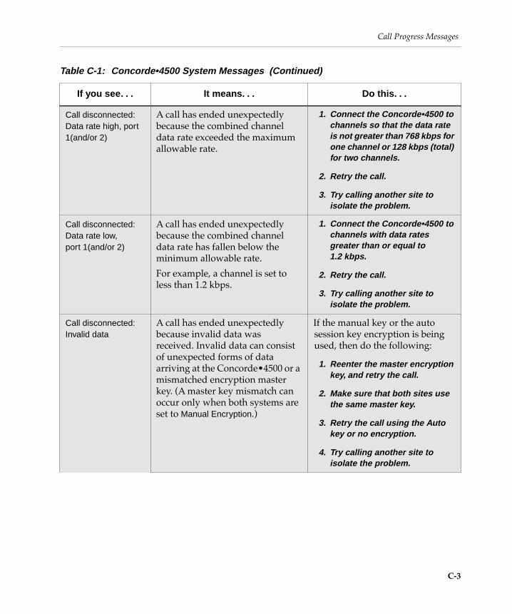
Call Progress Messages
Call disconnected:Data rate high, port 1(and/or 2)
A call has ended unexpectedly because the combined channel data rate exceeded the maximum allowable rate.
1. Connect the Concorde•4500 to channels so that the data rate is not greater than 768 kbps for one channel or 128 kbps (total) for two channels.
2. Retry the call.
3. Try calling another site to isolate the problem.
Call disconnected:Data rate low,port 1(and/or 2)
A call has ended unexpectedly because the combined channel data rate has fallen below the minimum allowable rate.
For example, a channel is set to less than 1.2 kbps.
1. Connect the Concorde•4500 to channels with data rates greater than or equal to 1.2 kbps.
2. Retry the call.
3. Try calling another site to isolate the problem.
Call disconnected:Invalid data
A call has ended unexpectedly because invalid data was received. Invalid data can consist of unexpected forms of data arriving at the Concorde¥4500 or a mismatched encryption master key. (A master key mismatch can occur only when both systems are set to Manual Encryption.)
If the manual key or the auto session key encryption is being used, then do the following:
1. Reenter the master encryption key, and retry the call.
2. Make sure that both sites use the same master key.
3. Retry the call using the Auto key or no encryption.
4. Try calling another site to isolate the problem.
Table C-1: Concorde•4500 System Messages (Continued)
If you see. . . It means. . . Do this. . .
C-3

SYSTEM MESSAGES
Call disconnected:Network lost, port 1 (and/or 2)
A call has ended unexpectedly because the signaling from the CSU indicates that the network connection or connections have been lost.
1. Try redialing the call.
2. Check the local CSU power and cabling and correct, if necessary; then call the far end to check the status of the far-end CSU, power, and cabling.
3. Try calling another site to isolate the problem.
Call disconnected:No channel on port 1 (and/or 2)
A call has ended unexpectedly because the clock signals expected from the CSU are missing.
1. Check the CSU power, switch settings, and cabling.
2. Try calling another site to isolate the problem.
Call disconnected:Far end
The far-end operator has disconnected the call using the normal disconnect (or hang-up) procedure.
(No action is required.)
Call disconnected:Non H.320 rateport 1 (and/or 2)
A call has ended unexpectedly because an invalid baud rate was detected for a call using ITU-T Recommendation H.320. Calls using the H.321 protocol must use baud rates in multiples of 56 or 64 kbps only.
1. Check the baud rate settings for your lines.
2. Make sure that baud rates for both lines are identical if you were attempting to make a two-channel call.
3. Check the cabling.
Call in progress The Concorde¥4500 has successfully connected to the system called. The system is now engaged in a call.
(No action is required.)
This message only appears brießy.
Table C-1: Concorde•4500 System Messages (Continued)
If you see. . . It means. . . Do this. . .
C-4

Call Progress Messages
Call not completed:Call setup failure
A dialed call from the Concorde¥4500 was not completed.
In this case, the far-end CSU answered the call but the Concorde¥4500 received no data or received invalid data from the far end.
1. Check that the numbers dialed are correct.
2. Try redialing the call.
3. Check the cabling between the Concorde•4500 and the network.
4. Ask the far-end operator to check the far-end cabling between the system and the network.
5. Try calling another site to isolate the problem.
Call not completed:Incompatible encryption
A call has been received with incompatible encryption settings.
For example, one site has the Set Encryption Mode screen set to Auto Key and the other site is set to Manual Key.
1. Make sure both sites are set for the same encryption settings on the Set Encryption Mode screen; then redial the call.
2. Redial the call without encryption.
3. Try calling another site to isolate the problem.
Call not completed:No channel, port 1 (or 2)
The Concorde¥4500 dialed an X.21 call but failed because no clock signal was present from one of the target CSUs.
(The clock signal is not required until after the network call is complete on RS-449 and V.35 interfaces.)
For example, this message appears when the Concorde¥4500 tries to dial a two-line call and only one CSU is available.
Check the CSU and data cabling.
Table C-1: Concorde•4500 System Messages (Continued)
If you see. . . It means. . . Do this. . .
C-5
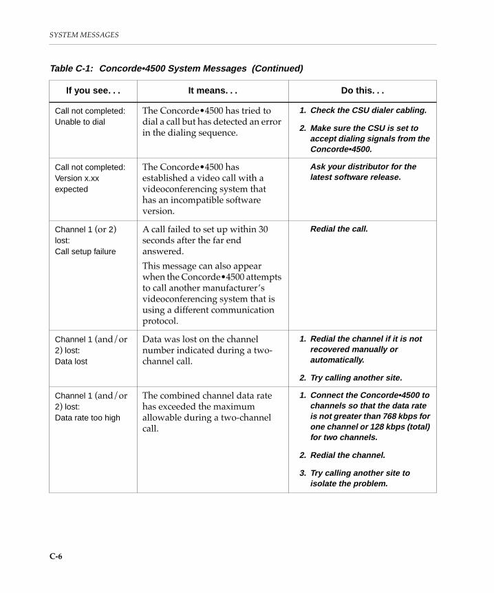
SYSTEM MESSAGES
Call not completed:Unable to dial
The Concorde¥4500 has tried to dial a call but has detected an error in the dialing sequence.
1. Check the CSU dialer cabling.
2. Make sure the CSU is set to accept dialing signals from the Concorde•4500.
Call not completed:Version x.xx expected
The Concorde¥4500 has established a video call with a videoconferencing system that has an incompatible software version.
Ask your distributor for the latest software release.
Channel 1 (or 2) lost:Call setup failure
A call failed to set up within 30 seconds after the far end answered.
This message can also appear when the Concorde¥4500 attempts to call another manufacturerÕs videoconferencing system that is using a different communication protocol.
Redial the call.
Channel 1 (and/or 2) lost:Data lost
Data was lost on the channel number indicated during a two-channel call.
1. Redial the channel if it is not recovered manually or automatically.
2. Try calling another site.
Channel 1 (and/or 2) lost:Data rate too high
The combined channel data rate has exceeded the maximum allowable during a two-channel call.
1. Connect the Concorde•4500 to channels so that the data rate is not greater than 768 kbps for one channel or 128 kbps (total) for two channels.
2. Redial the channel.
3. Try calling another site to isolate the problem.
Table C-1: Concorde•4500 System Messages (Continued)
If you see. . . It means. . . Do this. . .
C-6

Call Progress Messages
Channel 1 (and/or 2) lost:Data rate too low
The channel data rate has fallen below the minimum allowable, during a two-channel call. For example, a channel is set to less than 1.2 kbps.
1. Connect the Concorde•4500 to channels with data rates greater than 1.2 kbps.
2. Redial the channel.
3. Try calling another site to isolate the problem.
Channel 1 (and/or 2) lost:Far end
The far-end system detected a condition (for example, other Òchannel lostÓ messages) for which it stopped using one channel, during a two-channel call.
The far end must identify the particular reason for dropping the channel.
Redial the channel to enable the Concorde•4500 to recover.
Channel 1 (or 2) lost:Invalid data
Invalid data was received on the indicated port during a two-channel call.
Invalid data may consist of unexpected forms of data arriving at the Concorde¥4500 or a mismatched encryption master key. (A master key mismatch can occur only when both systems are set to Manual Encryption.)
1. Reenter the master encryption key and retry the call.
2. Make sure that both sites are set for the same encryption mode and are using the same master key.
3. Retry the call using the Auto key or no encryption.
4. Try calling another site to isolate the problem.
Table C-1: Concorde•4500 System Messages (Continued)
If you see. . . It means. . . Do this. . .
C-7

SYSTEM MESSAGES
Channel 1 (and/or 2) lost:Network lost
Two channels were lost during a two-channel call because the transmission channels have been lost on the indicated port. Clock signals are present, but the control signals from the CSU indicate that the connection was lost.
1. Try redialing the channel to enable the Concorde•4500 to recover.
2. Check the local CSU power and cabling and correct, if necessary.
3. Call the far end to check the status of the far-end CSU, power, and cabling.
4. Try calling another site to isolate the problem.
Channel 1 (and/or 2) lost:No channel connection
One channel was dropped from a two-channel call because the clock signals expected from the CSU are missing.
1. Check the CSU power, switch settings, and cabling.
2. Try redialing the channel to enable the Concorde•4500 to recover.
3. Try calling another site to isolate the problem.
Channel 1 (or 2) recovered
The indicated channel has become available and has been added to the call.
(No action is required.)
Connecting The near end has connected to the far end on a network level, and the systems are trying to achieve frame alignment.
(No action is required.)
Data transfer in progress
Data transmissions slow down or override video operation.
(No action is required.)
This message goes away when the data transfer is complete.
Dialing <number 1> <number 2>
The one- or two-line number is being dialed through the network.
(No action is required.)
Table C-1: Concorde•4500 System Messages (Continued)
If you see. . . It means. . . Do this. . .
C-8

Call Progress Messages
Encryption in use An encrypted call has been placed at both the near end and the far end.
(No action is required.)
This message goes away after ten seconds.
Incoming video call
or
Incoming voice call
or
Incoming video and voice call
An incoming call is detected and the Concorde¥4500 system is set to Manual Answer mode.
Press CALL/ADD to answer the call.
LAMB presets are currently full.
To add a new LAMB to the system, you must erase all current LAMB presets and reprogram those you want to keep. (The system will accept a maximum of 10 LAMB presets per camera.)
You tried to add another LAMB preset for the camera. However, the system is already storing the maximum of 10 LAMB presets for the camera.
To keep the LAMB presets as they are, choose No at the Erase All LAMB Presets prompt.
To add your preset, you must erase all of the LAMB presets and enter new presets.
1. At the Erase All LAMB Presets prompt, choose Yes to erase the presets.
2. To set the new LAMB presets, refer to the Concorde•4500 User’s Notebook .
Table C-1: Concorde•4500 System Messages (Continued)
If you see. . . It means. . . Do this. . .
C-9

SYSTEM MESSAGES
Line error The Concorde¥4500 system detects errors in the incoming data, indicating a possible network problem.
1. Check that the numbers dialed are correct.
2. Try redialing the call.
3. Check the cabling between the Concorde•4500 and the network.
4. Ask the far-end operator to check the far-end cabling between the videoconferencing system and the network.
5. Try calling another site to isolate the problem.
Local channel loopback
You are running a local channel loopback test.
(No action is required.)
Locally initiated remote loopback
You are running a remote loopback test.
(No action is required.)
Mute: Far end The far end has pressed MUTE. (No action is required.)
Mute: Near end The near end has pressed MUTE. (No action is required.)
Mute: Near and Far Ends
The near end and the far end have both pressed MUTE.
(No action is required.)
Negotiating The near end has connected to the far end and the systems are negotiating for an agreeable mode of operation.
(No action is required.)
Network Connected The near end has connected to the far end on a network level, and the systems are trying to achieve frame alignment.
(No action is required.)
Table C-1: Concorde•4500 System Messages (Continued)
If you see. . . It means. . . Do this. . .
C-10

Call Progress Messages
No answer The Concorde¥4500 has dialed a call that did not complete because the far-end CSU did not answer the call or a wrong number was dialed. This message may also appear when a speed-dial call has not been answered within one minute or when a dialed call has not been completed because invalid data was received.
1. Check that the numbers dialed are correct.
2. Try redialing the call.
3. Check the cabling between the Concorde•4500 and the network.
4. Ask the far-end operator to make sure the CSU is turned on and to check the cabling between the Concorde•4500 and the network.
5. Try calling another site to isolate the problem.
PictureTel Ready The Concorde¥4500 is ready to place or to receive a call.
(No action is required.)
Recalling snapshot You pressed RECALL SNAPSHOT on the wireless keypad, or VIEW SNAPSHOT on the QuickPad, and you are currently looking at a snapshot.
(No action is required.)
Receiving snapshot The far end has sent a freeze-frame graphic to the near end by pressing SEND SNAPSHOT.
(No action is required.)
This message goes away when the transfer of the graphic is complete.
System initialization in progressVersion x.xx
The Concorde¥4500 is powering on or the system self-tests are running.
(No action is required.)
This message typically lasts about one minute and is replaced by the PictureTel Ready message.
Video-audio loopback
You are running a video-audio loopback test.
(No action is required.)
Table C-1: Concorde•4500 System Messages (Continued)
If you see. . . It means. . . Do this. . .
C-11

SYSTEM MESSAGES
Video/audio test pattern
You are running a video-audio test pattern.
(No action is required.)
Waiting for Answer The near end is waiting for the far end to answer.
(No action is required.)
Waiting for other conference participants
You are the only site connected to an H.320 bridge.
Wait for other sites to join the conference.
Warning:data rate too high
The combined channel data rate has exceeded the maximum allowable rate.
1. Connect the Concorde•4500 to channels so that the data rate is not greater than 768 kbps for one channel or 128 kbps (total) for two channels.
2. Retry the call.
3. Try calling another site to isolate the problem.
Warning:data rate too low
The channel data rate is below the minimum allowable rate (for example, a channel is set to less than 1.2 kbps).
1. Connect the Concorde•4500 to channels with data rates greater than or equal to 1.2 kbps.
2. Retry the call.
3. Try calling another site to isolate the problem.
Warning:H.320 requires 56/64 kbps
The H.320 protocol is currently selected on the Set Video Send Mode screen, and the baud rate observed at the channel interface is not in multiples of 56 or 64 kbps, with the following exceptions: 7x56, 9x56, 10x56, 11x56, 7x64, 9x64, 10x64, and 11x64.
(No action is required.)
Table C-1: Concorde•4500 System Messages (Continued)
If you see. . . It means. . . Do this. . .
C-12

Call Progress Messages
Warning:Loss of far-end video
The far end has attempted to send video from a source that it does not have, such as an auxiliary video source, a VCR, a document camera, or an auxiliary graphics source.
1. Make sure that no one at the far end accidentally pressed a button for a device or option not configured with their system, such as SEND DOC, AUX A or B, or VCR.
2. Check the video power, the room controller switch settings, and the cable connections.
Warning:Network not ready
An X.21, 4-wire switched-56, or V.25 bis network is not ready to make or receive a call. Note that this condition might intentionally be set by the network.
1. Wait for the network to return to the Ready state.
2. Check the CSU power and connections.
3. Check all cabling between the Concorde•4500 system and the network.
Warning:No channel connection
The Concorde¥4500 cannot detect clock signals on both ports.
1. Check the CSU power and the connections of the lost channel.
2. Check all cabling between the Concorde•4500 and the network.
Warning:No video input
The Concorde¥4500 does not detect video signals from the near-end video equipment. This message could be displayed on your monitor if you attempt to send video from a source that you do not have, such as an auxiliary video source, a VCR, a document camera, or an auxiliary graphics source.
1. Make sure that no one accidentally pressed a button for a device or option not configured with your system, such as such as SEND DOC, AUX A or B, or VCR.
2. Check the video power, the room controller switch settings, and the cable connections at the near end.
Table C-1: Concorde•4500 System Messages (Continued)
If you see. . . It means. . . Do this. . .
C-13


D
X.21 Call ProgressMessages
This appendix describes the X.21 call progress messages that may appear on the monitor while you are using the Concorde¥4500.
Call progress messages tell you the advancing stage of your call as it connects, and, if there is a problem, why the call wonÕt go through.
The Concorde¥4500 generates some call progress messages internally. These appear on the screen regardless of your systemÕs network interface. The internal call progress messages are listed with the system messages in the table in Appendix C, ÒSystem Messages.Ó
The X.21 call progress messages are listed in the table on the next page. The messages are listed in order by X.21 code. The table contains three columns. The Þrst column lists the call progress message. The second column lists the X.21 text and code and, when appropriate, an explanation. When applicable, the third column lists the corresponding Q.931 cause and code.
There are two types of X.21 call progress messages:
❑ Normal messages
❑ Extended messages
F Y I F.Y.I. The X.21 call progress messages appear only if your system is conÞgured with an X.21 network interface and you are using an IMUX or a terminal adapter (TA) that supports X.21 messages.
D-1

X.21 CALL PROGRESS MESSAGES
Normal MessagesNormal messages display basic information.
When you display normal messages, and a call successfully connects, the text from the Þrst column of the following table appears. When a call fails to connect, the message includes a suggested user response, for example, Check number — dial again.
Extended MessagesExtended messages provide more technical detail than normal messages.
When you display extended messages, and a call successfully connects, the heading and code from the second column of the following table appear. When a call fails to connect, the message appears along with the suggested response from the Þrst column.
F Y I F.Y.I. You can conÞgure your system to display normal messages, extended messages, or no messages. To set the message type, choose Set Screen Message Display from the Set General ConÞguration menu, available from the ConÞguration menu.
Table D-1: X.21 Call Progress Signals and Q.931 Cause Codes
Message Text X.21 Signal and Code Q.931 Cause and Code
Ringing. Terminal called (01)
The incoming call was signaled to the Data Terminal Equipment (DTE) and call acceptance is awaited.
n/a
D-2

Call forwarded—ringing.
Redirected call (02)
The call has been redirected to another number assigned by the originally called subscriber, because, for example, it was busy.
n/a
Call is in queue.
Wait for connection.
Connect when free (03)
The called number is busy and the call has been placed in a queue. The call will be connected when the called number becomes free if the caller waits.
n/a
(None) Private network reached (04)
In the case of sub-addressing, the DTE may see call progress signals which have originated in the public network and/or the private network. In such cases the call progress signal Private network reached is used to discriminate between the different origins.
n/a
Table D-1: X.21 Call Progress Signals and Q.931 Cause Codes (Continued)
Message Text X.21 Signal and Code Q.931 Cause and Code
D-3

X.21 CALL PROGRESS MESSAGES
(None) Public network reached (05)
In the case of a DTE being connected to a private network which also provides for access to a public network, the DTE may see call progress signals which have originated in the private network and/or the public network. In such cases the call progress signal Public network reached is used by the private network in order to discriminate between the different origins.
n/a
Table D-1: X.21 Call Progress Signals and Q.931 Cause Codes (Continued)
Message Text X.21 Signal and Code Q.931 Cause and Code
D-4

No Answer.
Try again later.
No Connection (20)
Cause unspeciÞed.
No answer from user, user alerted (19)
This cause is used when the called party has been alerted but does not respond with a connect indication within a prescribed period of time. This cause is not necessarily generated by Q.931 procedures but may be generated by internal network timers.
No user responding (18)
This cause is used when a called party does not respond to a call establishment message with either an alerting or connect indication within the prescribed period of time allocated.
No circuit/channel available (34)
This cause indicates that there is no appropriate circuit/channel presently available to handle the call.
Requested circuit/channel not available (44)
This cause is returned when the circuit or channel indicated by the requesting entity cannot be provided by the other side of the interface.
Service or option not available, unspeciÞed (63)
This cause is used to report a service or option not available event only when no other cause in the service or option not available class applies.
Table D-1: X.21 Call Progress Signals and Q.931 Cause Codes (Continued)
Message Text X.21 Signal and Code Q.931 Cause and Code
D-5

X.21 CALL PROGRESS MESSAGES
Number dialed is busy.Try again later.
Number busy (21)
The called DTE is detected by the Data Communications Equipment (DCE) as engaged on other call(s), and therefore as not being able to accept the incoming call.
User busy (17)
This cause is used to indicate that the called party is unable to accept another call because the user busy condition has been encountered. This cause value may be generated by the called user or by the network. In the case of user determine user busy, it is noted that the user equipment is compatible with the call.
Table D-1: X.21 Call Progress Signals and Q.931 Cause Codes (Continued)
Message Text X.21 Signal and Code Q.931 Cause and Code
D-6

Cannot complete call as dialed.
Check number—dial again.
(continued next page)
Selection signals procedure error (22)
Invalid number format, address incomplete (28)
This cause indicates that the called party cannot be reached because the called party number is not in a valid format or is not complete. This condition may be determined either immediately after reception of an ST signal or on time-out after the last received digit.
Mandatory information element is missing (96)
This cause indicates that the equipment sending this cause has received a message that is missing an information element which must be present in the message before that message can be processed.
Message type non-existent or not implemented (97)
This cause indicates that the equipment sending this cause has received a message with a message type it does not recognize either because this is a message not deÞned or deÞned but not implemented by the equipment sending this cause.
Message not compatible with call state or message type non-existent or not implemented (98)
This cause indicates that the equipment sending this cause has received a message such that the procedures do not indicate that this is a permissible message to receive while in the call state, or a STATUS message was received indicating an incompatible call state.
Table D-1: X.21 Call Progress Signals and Q.931 Cause Codes (Continued)
Message Text X.21 Signal and Code Q.931 Cause and Code
D-7

X.21 CALL PROGRESS MESSAGES
Cannot complete call as dialed.
Check number—dial again.
(continued)
Selection signals procedure error (22)
Information element/parameter non-existent or not implemented (98)
This cause indicates that the equipment sending this cause has received a message that includes information element(s)/parameter(s) not recognized because the information element identiÞer(s)/parameter name(s) are not deÞned or are deÞned but not implemented by the equipment sending the cause. This cause indicates that the information element(s)/parameter(s) were discarded. However, the information element is not required to be present in the message in order for the equipment sending the cause to process the message.
Message not compatible with call state (101)
This cause indicates that a message has been received which is incompatible with the call state.
Protocol error, unspeciÞed (111)
This cause is used to report a protocol error event only when no other cause in the protocol error class applies.
Table D-1: X.21 Call Progress Signals and Q.931 Cause Codes (Continued)
Message Text X.21 Signal and Code Q.931 Cause and Code
D-8

Network signaling error.
Report if problem persists.
Selection signal transmission error (23)
A transmission error has been detected in the selection signals by the Þrst Data Switching Exchange (DSE).
Invalid information element contents (100)
This cause indicates that the equipment sending this cause has received an information element which it has implemented; however, one or more Þelds in the information element are coded in a way which has not been implemented by the equipment sending this cause.
Invalid message, unspeciÞed (95)
This cause is used to report an invalid message event only when no other cause in the invalid message class applies.
Number dialed is unreachable.
Report if problem persists.
Access barred (41)
The calling DTE is not permitted the connection to the called DTE. Possible reasons include unauthorized access between the calling DTE and the called DTE or an incompatible closed user group.
n/a
Number dialed has changed.
Obtain and dial new number.
Changed number (42)
The called DTE has been assigned a new number.
Number changed (22)
This cause is returned to a calling party when the called party number indicated by the calling party is no longer assigned. The new called party number may optionally be included in the diagnostic Þeld. If a network does not support this cause value, cause No. 1, unallocated (unassigned) number is used.
Table D-1: X.21 Call Progress Signals and Q.931 Cause Codes (Continued)
Message Text X.21 Signal and Code Q.931 Cause and Code
D-9

X.21 CALL PROGRESS MESSAGES
Number dialed is unassigned.
Check number—dial again.
(continued next page)
Not obtainable (43)
The called DTE address is out of the numbering plan or not assigned to any DTE.
Unallocated (unassigned) number (1)
This cause indicates that the called party cannot be reached because, although the called party number is in a valid format, it is not currently allocated (assigned).
No route to destination (3)
This cause indicates that the called party cannot be reached because the network through which the call has been routed does not serve the destination desired. This cause is supported on a network-dependent basis.
Channel unacceptable (6)
This cause indicates that the channel most recently identiÞed is not acceptable to the sending entity for use in this call.
Invalid call reference value (81)
This cause indicates that the equipment sending this cause has received a message with a call reference which is not currently in use on the user-network interface.
IdentiÞed channel does not exist (82)
This cause indicates that the equipment sending this cause has received a request to use a channel not activated on the interface for a call. For example, if a user has subscribed to those channels on a primary rate interface numbered from 1 to 12 and the user equipment or the network attempts to use channels 13 through 23, this cause is generated.
Table D-1: X.21 Call Progress Signals and Q.931 Cause Codes (Continued)
Message Text X.21 Signal and Code Q.931 Cause and Code
D-10

Number dialed is unassigned.
Check number—dial again.
(continued)
Not obtainable (43)
The called DTE address is out of the numbering plan or not assigned to any DTE.
Incompatible destination (88)
This cause indicates that the equipment sending this cause has received a request to establish a call which has low layer compatibility, high layer compatibility, or other compatibility attributes (for example, data rate) which cannot be accommodated.
Recovery on timer expiry (102)
This cause indicates that a procedure has been initiated by the expiry of a timer in association with error handling procedures.
Temporary network failure.
Report if problem persists.
Out of order (44)
The remote number is out of order. Possible reasons include:
❑ DTE is uncontrolled not ready
❑ DCE power off
❑ Network fault in the local loop; in packet switched services only:
¥ X.25 layer 1 not functioning
¥ X.25 layer 2 not in operation
Temporary failure (41)
This cause indicates that the network is not functioning correctly and that the condition is not likely to last a long period of time; the user may wish to try another call attempt almost immediately.
Network out of order (38)
This cause indicates that the network is not functioning correctly and that the condition is likely to last a relatively long period of time; immediately re-attempting the call is not likely to be successful.
Table D-1: X.21 Call Progress Signals and Q.931 Cause Codes (Continued)
Message Text X.21 Signal and Code Q.931 Cause and Code
D-11

X.21 CALL PROGRESS MESSAGES
Call rejected by network.
Report if problem persists.
Controlled not ready (45)
Called DTE is signaling controlled not ready.
Call rejected (21)
This cause indicates that the equipment sending this cause does not wish to accept this call, although it could have accepted the call because the equipment sending this cause is neither busy nor incompatible.
This cause may also be generated by the network, indicating that the call was cleared due to a supplementary service constraint. The diagnostic Þeld may contain additional information about the supplementary service and reason for rejection.
Destination is out of order.
Notify end-user at destination.
Uncontrolled not ready (46)
Called DTE is uncontrolled not ready.
Destination out of order (27)
This cause indicates that the destination indicated by the user cannot be reached because the interface to the destination is not functioning correctly. The term Ònot functioning correctlyÓ indicates that a signaling message was unable to be delivered to the remote party; for example, a physical layer or data link layer failure at the remote party, or user equipment off-line.
Destination is not powered.
Notify end-user at destination.
DCE power off (47)
Called DCE has no main power or is switched off.
n/a
Table D-1: X.21 Call Progress Signals and Q.931 Cause Codes (Continued)
Message Text X.21 Signal and Code Q.931 Cause and Code
D-12

Bearer capability not implemented.
Report if problem persists.
Invalid facility request (48)
A facility requested by the calling DTE (circuit switching or packet switching services) or the called DTE (packet switching service only) is detected as invalid by the DCE at the local DTE/DCE interface. Possible reasons include a request for a facility which has not been subscribed to by the DTE; a request for a facility which is not available in the local network; or a request for a facility which has not been recognized as valid by the local DCE.
Bearer capability not implemented (65)
This cause indicates that the equipment sending this cause does not support the bearer capability requested.
Channel type not implemented (66)
This cause indicates that the equipment sending this cause does not support the channel type requested.
Service or option not implemented, unspeciÞed (79)
This cause is used to report a service or option not implemented event only when no other cause in the service or option not implemented class applies.
Local loop fault at destination.
Notify end-user at destination.
Network fault in local loop (49)
The local loop associated with the called DCE is faulty.
n/a
Number temporarily unreachable.
Report if problem persists.
Call the information service (51)
The called number is temporarily unobtainable. Call the network information service for details.
n/a
Table D-1: X.21 Call Progress Signals and Q.931 Cause Codes (Continued)
Message Text X.21 Signal and Code Q.931 Cause and Code
D-13

X.21 CALL PROGRESS MESSAGES
Bearer capability not authorized.
Report if problem persists.
Incompatible user class of service (52)
The called DTE belongs to a user class of service which is incompatible with that of the calling DTE.
Bearer capability not authorized (57)
This cause indicates that the user has requested a bearer capability which is implemented by the equipment which generated this cause but which the user is not authorized to use.
All circuits are busy.
Try again later.
Network congestion (61)
A condition exists in the network such as temporary network congestion, temporary fault condition within the network (including procedure error within a network), or an international link.
Switching equipment congestion (42)
This cause indicates that the switching equipment generating this cause is experiencing a period of high trafÞc.
Resource unavailable, unspeciÞed (47)
This cause is used to report a resource unavailable event only when no other cause in the resource unavailable class applies.
Bearer capability not presently available (58)
This cause indicates that the user has requested a bearer capability which is implemented by the equipment which generated this cause but which is not available at this time.
All circuits are busy.
Try again later.
Long-term network congestion (71)
A major shortage of network resource exists.
n/a
Table D-1: X.21 Call Progress Signals and Q.931 Cause Codes (Continued)
Message Text X.21 Signal and Code Q.931 Cause and Code
D-14

Network interworking problem.
Report if problem persists.
RPOA out of order (72)
The Remote Point of Access (RPOA) nominated by the calling DTE is unable to forward the call.
Interworking, unspeciÞed (127)
This cause indicates that there has been interworking with a network which does not provide causes for actions it takes. Thus, the precise cause for a message which is being sent cannot be ascertained.
[none] Registration/cancellation confirmed (81)
The facility registration or cancellation requested by the calling DTE has been conÞrmed by the network.
n/a
[none] Redirection activated (82)
The redirection facility is active.
n/a
[none] Redirection deactivated (83)
The redirection facility is not active.
n/a
Table D-1: X.21 Call Progress Signals and Q.931 Cause Codes (Continued)
Message Text X.21 Signal and Code Q.931 Cause and Code
D-15

X.21 CALL PROGRESS MESSAGES
[none] n/a Normal call clearing (16)
This cause indicates that the call is being cleared because one of the users involved in the call has requested that the call be cleared. Under normal situations, the source of this cause is not the network.
Normal, unspeciÞed (31)
This cause is used to report a normal event only when no other cause in the normal class applies.
Quality of Service not available (49)
This cause is used to report that the requested Quality of Service, as deÞned in Recommendation X.213, cannot be provided (for example, throughput or transit delay cannot be supported).
Call proceeding Your call is being connected. (91)
n/a
Call delivered Your call is waiting to be answered. (92)
n/a
Table D-1: X.21 Call Progress Signals and Q.931 Cause Codes (Continued)
Message Text X.21 Signal and Code Q.931 Cause and Code
D-16

Index
Numerics
1-kHz toneused to adjust audio 5-23used to adjust video 5-19
A
AC power frequency, testing 4-17
adjustingaudio 5-22focus 5-36iris 5-37near-end camera 5-29video levels 5-17volume 5-22white balance 5-26
Adtran 2-18
answer modeautomatic 2-21manual 2-21selecting 2-21
Ascend 2-18
audio configuration, setting 5-10
audio signal processing, setting 5-16
audio telephone network, attaching cables to 2-14
audio transmission format 5-13
audio, adjusting 5-22
Auto IMUX Dialingconfiguring 2-15tips for using 3-8
Auto white balance mode 5-27
B
baud ratesetting for Control Port A 6-2setting for Control Port B 6-4setting for data ports 6-11
Belden 9732 cable 2-5
bit transmission ratesRS-449 channel 2-7SG3 protocol 2-7SG4 protocol 2-7
blue filter 5-19
C
cables, digital network 2-2
Index-1

cabling guidelinesfor RS-449 network interface 2-7for X.21 network interface 2-9
Call Log 7-29
call parameters 7-9
call rates, setting 2-20
camera failure, corrective actions 8-10
camera operation, setting 5-5
camera power-up default settings 5-26
camera white balance 5-17
Camera White Balance Adjust menu 5-28, 5-31
camerasadjusting near-end 5-29auxiliary 1-7changing pan direction 5-6erasing LAMB presets 5-7optional 1-7PowerCam 100 1-7setting control by far end 5-5
Chair control mode menu tree B-5
CHAN connectors 2-6
changing the password 4-12
Channel Service Unit. See CSU
channel, setting keypad 4-15
character grid 1-14
CIF (Common Intermediate Format) 2-27, 5-2, 5-4
coloradjusting 5-19adjusting in one-touch mode 5-27
communications failure, corrective actions 8-7
Concorde¥4500 UserÕs Notebook 1-16
Concorde¥4500, description of 1-1
Configuration menu 6-3, 6-6
Configuration menu tree B-3
Control Port A, setting 6-2
Control Port B, setting 6-3
CSUdaughter board 7-24description 2-2messages 7-14self-test 7-22signals 7-14
D
Data Communications Equipment. See DCE
Data Interface board 6-6
data ports, setting 6-6
Data Terminal Equipment. See DTE
Data Unit switches, settings for 2-13
Data Unit User Guide 2-12
DATAPATH Data Units 2-11
DC-37 connector 2-5
DCE (Data Communications Equipment) D-6
default settingscamera power-up 5-26factory settings A-1restoring 4-18
Diagnostics menu 7-3
Diagnostics menu tree B-4
dialed four-wire CSDC network 2-3
dialed networks 2-9
Index-2

Dialing Directorycreating an entry 3-2managing 3-8modifying an entry 3-5removing an entry 3-7updating IMUX codes 2-20
Dialing Directory screen 3-1
digital network cables, attaching 2-2
digital networks, types of 2-1
Director mode menu tree B-6
DPUs (Northern Telecom DATAPATH Data Units) 2-5
DSE (Data Switching Exchange) D-9
DTE (Data Terminal Equipment) D-2
E
echo 7-19
echo canceler 5-23
electrical current, verifying 8-14
electronics module 1-6
encryptionDES encryption 4-5disabling 4-7during local channel loopback test 7-21removing 4-10setting for an external device 4-7setting for dialed calls 4-8setting for nondialed calls 4-9with broadcast mode 4-5
Encryption Mode screen 4-6
Encryption mode, setting 4-5
entering information 1-14
erasing LAMB presets 5-7
external devices, communicating with 6-6
F
factory default settings A-1
far-end camera control 5-5
far-end tests, running 7-24
fault codes, clearing 7-4
fault history 8-3
flow control 6-4, 6-12
focus and iris adjustment settings 5-33
focus, adjusting 5-36
four-wire CSDC 56-kb network 2-2
four-wire DDS line 2-2
frame rates 2-27, 7-4
G
G.711 format 5-17
Gain, Focus, and Iris Adjust menu 5-35, 5-36, 5-37
general configuration, setting 4-1
general system messages C-1
graphics monitor 1-5
H
H.261 5-4
H.261 network statistics 7-7
H.263 5-4
H.263 network statistics 7-7
H.320 5-3
Index-3

H.320 network statistics 7-7
H.331 broadcast modeand encryption 4-5description of 2-25
HELP button 1-15
help, description of 1-15
I
IDEC (Integrated Dynamic Echo Cancellation) 5-16
IDEC II 5-16, 7-13
IMUX call rates, setting 2-20
IMUX codes, setting 2-19
IMUX type, setting 2-18
indoor adjustment mode 5-32
iris, adjusting 5-37
ISDN network, description of 2-2
K
keypadQuickPad 4-16wireless 1-3
keypad channel, setting 4-15
L
LAMBdescription of 1-11erasing presets 5-7
language, setting 4-4
lapel microphone mode 5-12
letter grid. See character grid
LimeLight failure, corrective actions 8-11
LimeLight, description of 1-8
Link-64E. See H.261
local channel loopback test 7-21
log. See Call Log
Look-At-Me-Button. See LAMB
loudspeaker distortion 7-19
M
M-34 connectors 2-5
Madge 2-18
menu trees B-1
menusCamera White Balance Adjust 5-28, 5-31Configuration 6-3, 6-6Diagnostics 7-3Gain, Focus, and Iris Adjust 5-35,
5-36, 5-37navigating through 1-14Near-End Tests 5-18, 5-24, 7-19Set Audio Configuration 5-10, 5-16, 5-17Set Data Port Configuration 6-1, 6-3, 6-6Set General Configuration 4-1Set Language 4-4Set Microphones 5-12Set Network Configuration 2-15, 2-22Set Network Interface 2-16Set Video Configuration 5-1, 5-5, 5-6, 5-7Set Video Transmission Format 5-3Setup 1-13Update Dialing Directory 2-21View Diagnostics 5-18
messages C-1
Index-4

microphoneslapel 1-9PowerMic 1-9setting 5-11
modem 7-26
modular processor data modules (MPDMs) 2-5
monitorsdescription of 1-5selecting number of 5-9
MPDMs (modular processor data modules) 2-5
N
navigating through menus 1-14
near-end camera, adjusting 5-29
near-end interface electronics, testing 7-20
near-end site name, setting 4-13
Near-End Tests menu 5-18, 5-24, 7-19
near-end tests, running 7-15
network failure, corrective actions 8-7
network interface, connecting to 2-1
Network Manager 6-5
network statisticsclearing 7-4H.261 7-7H.263 7-7H.320 7-7SG3 7-5SG4 7-7viewing 7-4
no audio, corrective actions 8-6
no display on monitor, corrective actions 8-5
no system power, corrective actions 8-4
nondialed DDS network, connecting to 2-3
nondialed mode 2-7
nondialed networks 2-9
Northern Telecom DATAPATH Data Units (DPUs) 2-5
NTSC, resolution with 5-4
O
One Touch Mode screen 5-31
outdoor adjustment mode 5-32
P
PAL, resolution with 5-4
paritysetting for Control Port A 6-2setting for Control Port B 6-4setting for data ports 6-11
Pass-Fail status 8-2
password protection 4-11
password, changing 4-12
peripheral failure, corrective actions 8-10
POTS telephone line, connecting to 2-14
PowerCam 100, description of 1-7
PowerMic, description of 1-9
power-on self-test 8-2
power-on, verifying 8-2
Promptus 2-18
PSDN connection 2-3
PT716plus 5-14
Index-5

Q
QCIF (Quarter Common Intermediate Format) 2-27, 5-2, 5-4
QuickPaddescription of 1-4illustration of 1-4
R
record mode settings 5-8
remote CSU loopback test, running 7-25
remote diagnostic mode, entering 7-27
remote diagnostics option 7-1
remote diagnostics service 7-26
remote video-audio loopback test, running 7-24
resolution 5-4
restoring default settings 4-18
restricted channel 2-27
RS-366A interface 2-5
RS-449 channel, bit transmission rates 2-7
RS-449 connector 2-2
RS-449 network interface, cabling guidelines for 2-7
RS-449 network interface, connecting to 2-8
S
screensCall Log 7-29Encryption Mode 4-6One Touch Mode 5-31Select Interface 2-17Select Manual Format 5-3
Set Audio Signal Processing 5-16Set H.331 Audio Send 2-27Set H.331 Video Send 2-27Set Two-Line Dialing 2-25System Configuration 7-2
Select Interface screen 2-17
Select Manual Format screen 5-3
serial automatic dialingV.25 network interface 2-11X.21 network interface 2-9
serial ports 6-6
Set Audio Configuration menu 5-10,5-16, 5-17
Set Audio Signal Processing screen 5-16
Set Data Port Configuration menu 6-1, 6-3, 6-6
Set General Configuration menu 4-1
Set H.331 Audio Send screen 2-27
Set H.331 Video Send screen 2-27
Set Language menu 4-4
Set Microphones menu 5-12
Set Network Configuration menu 2-15, 2-22
Set Network Interface menu 2-16
Set Two-Line Dialing screen 2-25
Set Video Configuration menu 5-1, 5-5, 5-6, 5-7
Set Video Transmission Format menu 5-3
SETUP button 3-2, 3-5, 3-7
Setup menu 1-13
Setup menu tree B-2
Index-6

SG3description of 5-4network statistics 7-5
SG4description of 5-4network statistics 7-7
SMPTE color barsdisplaying 5-18test pattern 5-19
sound pressure meter 5-24
standby mode timer 4-14
System Configuration screen 7-2
system fault codes 7-12
system messages C-1
system options 7-13
system warning messages 8-12
T
tabletop microphone mode 5-12
telephone line, connecting to 2-14
test configuration, setting 7-22
troubleshooting procedures 8-3
two-line dialing mode, selecting 2-25
U
Update Dialing Directory menu 2-21
V
V.25 bis network interface, description of 2-11
V.35 bis network interfaceconnecting to the Data Unit 2-11data transmission rates 2-11
V.35 network interfaceconnecting to 2-6connection panel and adapter cable 2-6data transmission rates 2-5description of 2-5
VCR failure, corrective actions 8-11
VCR operation, setting 5-8
VCRs, connecting 5-8
verifying power-on 8-2
video adjustments 5-19
video configuration, setting 5-1
video transmission formatautomatic mode 5-3manual mode 5-3setting 5-2
video-audio loopback 7-20
video-audio test patterns 5-23, 7-19
View Diagnostics menu 5-18
W
warning messages 8-12
white balance, adjusting 5-26
wireless keypaddescription of 1-3illustration of 1-3setting channel 4-16
WorldCart, description of 1-10
Index-7

X
X.21 call progress messagesextended D-1normal D-1
X.21 network interfaceconnecting to 2-10connection panel 2-10data transmission rates 2-9description of 2-9
Index-8