p&id’s piping & instrumentation diagrams. format & layout title block sheet number...
TRANSCRIPT
P&ID’s
PIPING & INSTRUMENTATION DIAGRAMS

Format & Layout Title Block
Sheet Number Revision Number Date
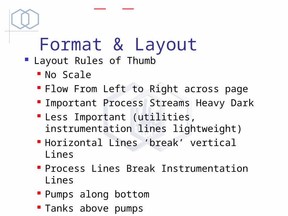
Format & Layout Layout Rules of Thumb
No Scale Flow From Left to Right across page Important Process Streams Heavy Dark Less Important (utilities, instrumentation
lines lightweight) Horizontal Lines ‘break’ vertical Lines Process Lines Break Instrumentation
Lines Pumps along bottom Tanks above pumps
P&ID’s - Symbology Equipment Symbology Instrumentation Symbology
See the document “P&ID Symbols and Photos.DOC”
P&ID’s - Equipment Keep in mind the development of the P&ID’s
is really developing the process The way it will start-up / shut-down and
normally operate Procedure
Start with the Simulation and Equipment List
Draw Equipment (including spares) Draw the major process Lines, then Utilities

P&ID’s - Safety - ALWAYS!!!!! ALWAYS Consider Safety!!
Think, what happens if the control valve doesn’t operate as intended?
What happens if the pump stops working? How will the operators troubleshoot the problem? What if the operators ignore an alarm ...
Consider the need for redundant controls and equipment, but only if deemed necessary.
Redundant things are twice as likely to fail!
P&ID’s - Simplicity Rules The easiest process to operate and
understand is the simplest one K.I.S.S. Add “indicators” (flow, pressure,
temperature) for trouble shooting Don’t add “controls” unless they are
absolutely necessary Only resort to complicated controls when
you have to... Consider the consequences of operators not understanding them.
P&ID’s - Rookie Mistakes Don’t put level control on Storage Tanks
They’re there to take up variations in flow, therefore the level is supposed to ‘float’
Let Pressures in the process ‘float’ as much as possible, try not to over control operating pressures.
Don’t try to control liquid flow at two points in a pipe - remember conservation of mass
Don’t look at one P&ID only - Look at the big picture then consider the details
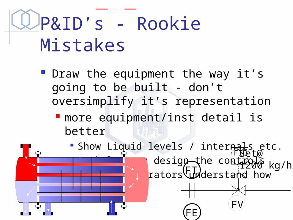
P&ID’s - Rookie Mistakes Draw the equipment the way it’s going
to be built - don’t oversimplify it’s representation more equipment/inst detail is better
Show Liquid levels / internals etc. It helps you design the controls It helps operators understand how it
works
FV
FT
FIC
FE
Set@1200 kg/hr
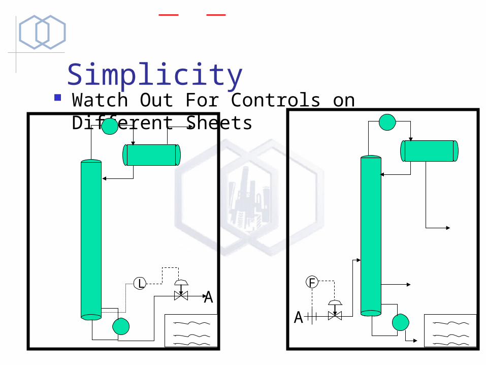
Simplicity Watch Out For Controls on Different
Sheets
AA
L F
P&ID’s - Costs Are Important Goal: Lowest Capital costs and Lowest
Operating Costs. Only build what’s required The Cheapest Process that meets the
need of all involved is the most profitable.
It’s got to work! After that, make it cheap as possible.
P&ID’s - Control The Flow that occurs in a pipe is a
function of the Pressure Drop.
Valves add or subtract from the natural pressure drop of the pipe.
Valves change the pressure drop to give us the flow rate we want
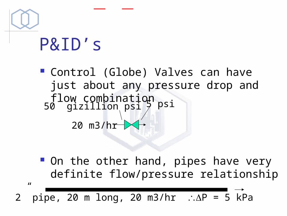
P&ID’s Control (Globe) Valves can have just
about any pressure drop and flow combination
On the other hand, pipes have very definite flow/pressure relationship
50 gizillion psi 5 psi
20 m3/hr
2” pipe, 20 m long, 20 m3/hr P = 5 kPa
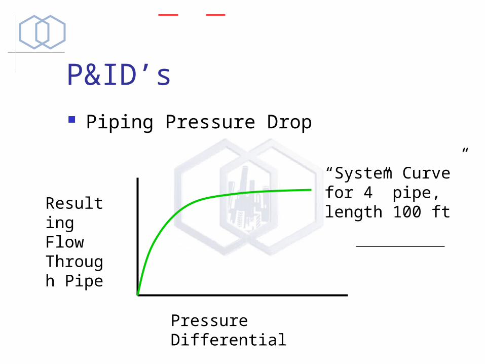
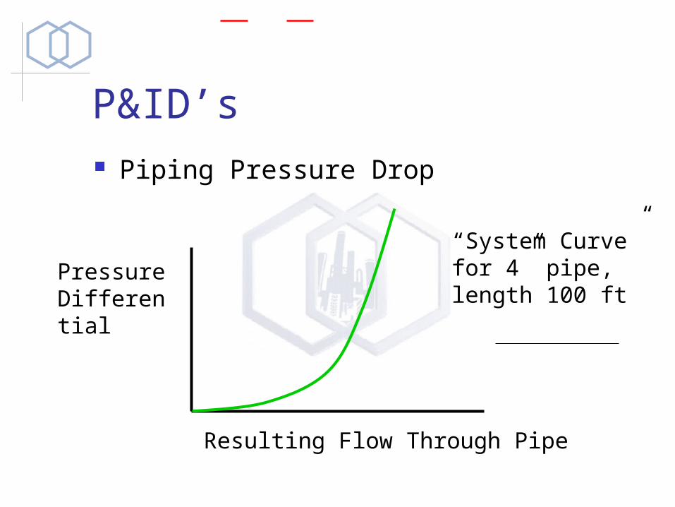
P&ID’s Piping Pressure Drop
Resulting Flow Through Pipe
Pressure Differential
“System Curve”for 4” pipe, length 100 ft
P&ID’s Piping Pressure Drop
Resulting Flow Through Pipe
Pressure Differential
“System Curve”for 4” pipe, length 100 ft
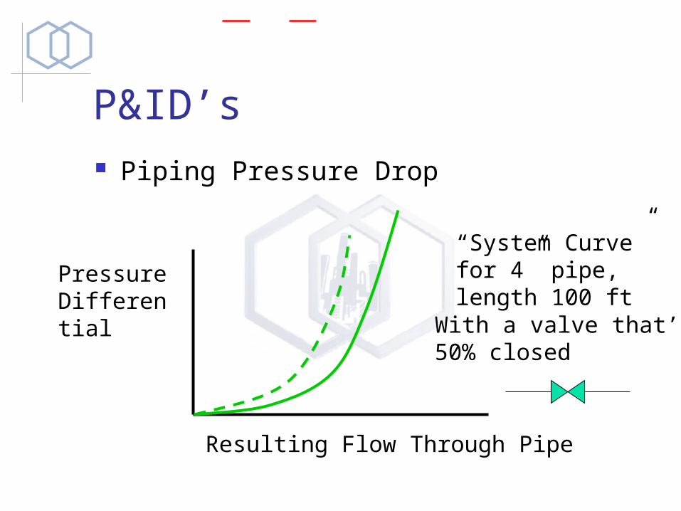
P&ID’s Piping Pressure Drop
Resulting Flow Through Pipe
Pressure Differential
“System Curve”for 4” pipe, length 100 ftWith a valve that’s50% closed
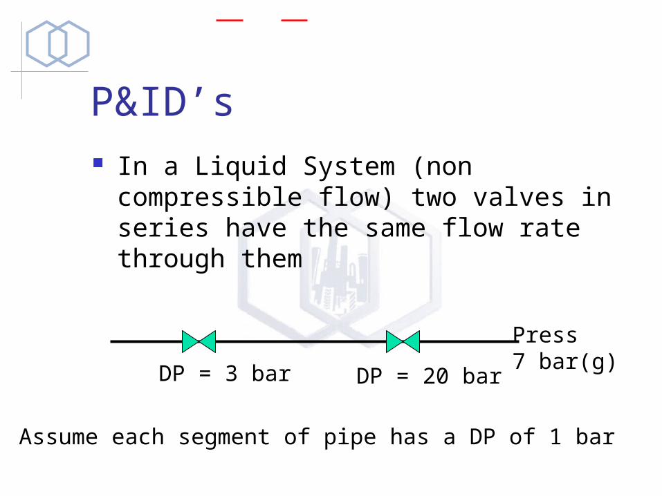
P&ID’s In a Liquid System (non compressible
flow) two valves in series have the same flow rate through them
DP = 3 bar DP = 20 bar
Press7 bar(g)
Assume each segment of pipe has a DP of 1 bar
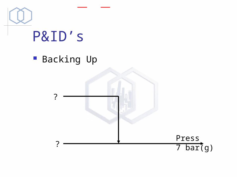
P&ID’s Backing Up
Press7 bar(g)
?
?
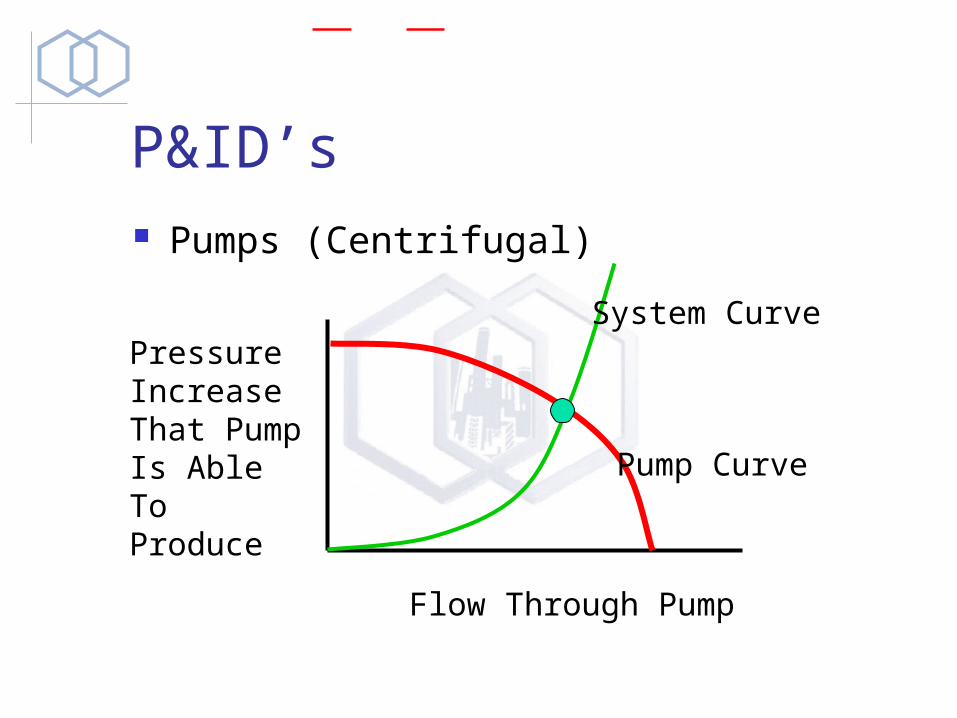
P&ID’s Pumps (Centrifugal)
Flow Through Pump
Pressure Increase That Pump Is Able To Produce Pump Curve
System Curve
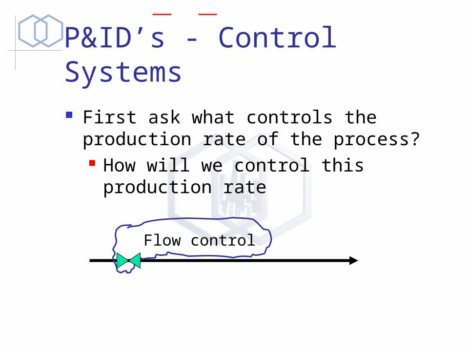
P&ID’s - Control Systems First ask what controls the production
rate of the process? How will we control this production
rate
Flow control
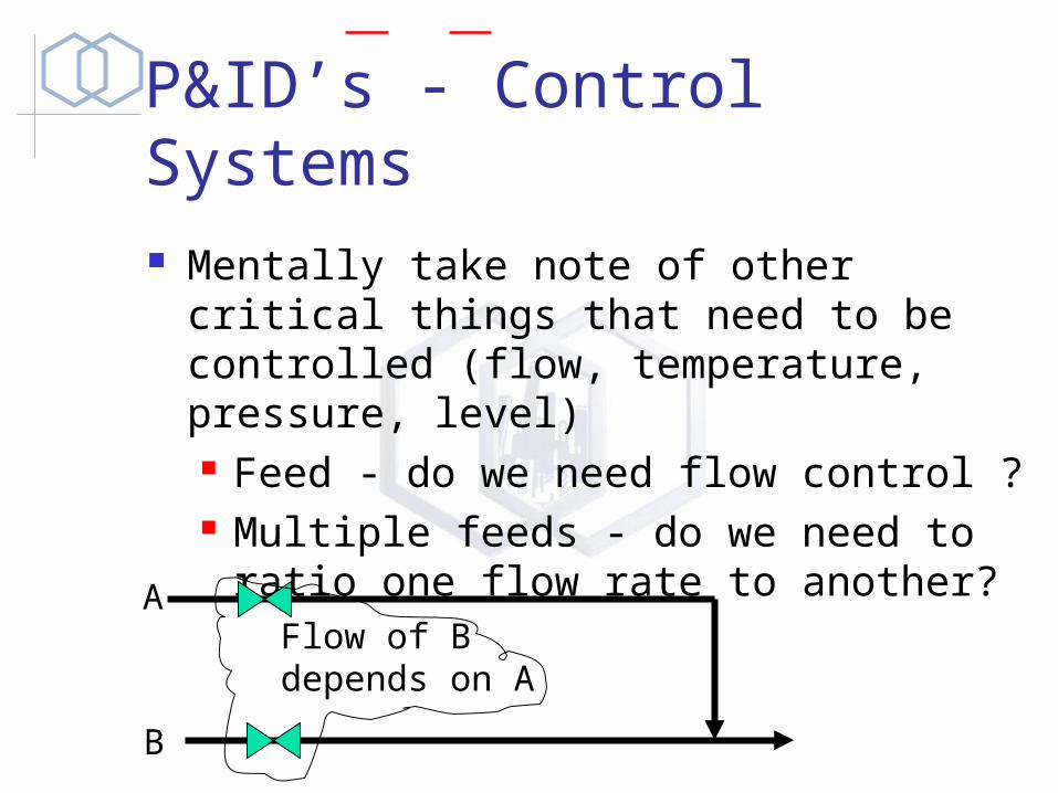
P&ID’s - Control Systems Mentally take note of other critical
things that need to be controlled (flow, temperature, pressure, level) Feed - do we need flow control ? Multiple feeds - do we need to ratio
one flow rate to another?
Flow of B depends on A
A
B

Ratio Control
FV
FT
FIC
FE
FV
FT
FRIC
FE
PrimaryRate
RatioToPrimary
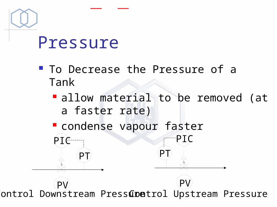
Pressure To Decrease the Pressure of a Tank
allow material to be removed (at a faster rate)
condense vapour faster
PIC
PT
PV
PIC
PV
PT
Control Downstream Pressure Control Upstream Pressure
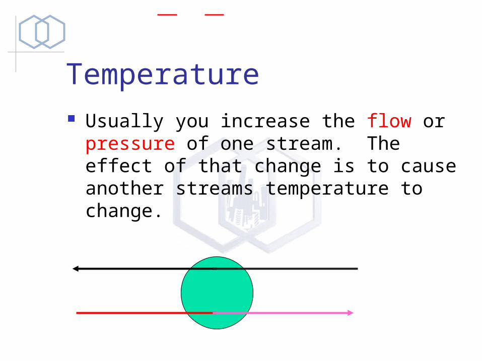
Temperature Usually you increase the flow or
pressure of one stream. The effect of that change is to cause another streams temperature to change.

Level To Decrease the Level of a Tank
allow material to be removed (at a faster rate)
Tanks and Pumps Always Provide a way of preventing your
pumps from running dry Always Provide a way of preventing your
pumps from being “dead headed” Recirc the pump discharge to the tank with a
“minimum flow bypass”
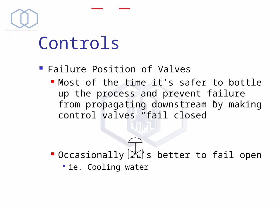
Controls Failure Position of Valves
Most of the time it’s safer to bottle up the process and prevent failure from propagating downstream by making control valves “fail closed”
Occasionally it’s better to fail open ie. Cooling water