piezoelectric feeder controller afc series - bfc-co.jp · piezoelectric feeder controller afc...
TRANSCRIPT

Piezoelectric Feeder Controller
AFC Series AFC -20HG AFC-20SE
Instruction Manual
Thank you for purchasing the controller manufactured by BFC Limited.
Please read this instruction manual thoroughly before use for proper
use of the product.
This instruction manual should be handed to the end user.
1. Before use About vibrator
Be sure to use the specified piezoelectric feeder (AFR-xxxD,
AFJ-xxxD, AFB-xxxD series).
*This product cannot be used with an electromagnetic feeder.
2. Safety precautions Precautions are classified into “Danger,” “Warning” and “Caution”
depending on the degree of risk in this instruction manual.
Danger
△!
Hazards are obviously anticipated.
If the product is handled in an improper manner neglecting the
indication, death or serious injury may occur.
Warning
△!
Hazards may occur depending on the situation.
If the product is handled in an improper manner neglecting the
indication, death or serious injury may occur.
Caution
△!
Hazards may occur depending on the situation.
If the product is handled in an improper manner neglecting the
indication, minor or medium-level injury may occur.
The Danger, Warning and Caution below do not cover all possible
cases.
Read the catalog and the instruction manual carefully and place priority
on the safety in performing operations.
Danger
△!
To prevent electrical shock, do not perform operations in live wire
state.
To prevent catching fire, do not use at places with hazardous
objects such as ignitable objects and flammable objects.
*The product is not explosion-proof.
If the product is installed at a high place, it may drop or fall
depending on conditions.
Provide measures against drop and fall. Moreover, retain and fix
firmly in installing the product.
Do not splash water on the product, wash the product or use the
product under water to avoid injury, electrical shock or fire due to
malfunction.
Warning
△!
Shut OFF the power supply before removing the cover.
Be sure to shut OFF the power supply before performing wiring to
avoid electrical shock.
Do not insert/remove the connector while the power supply is ON
or apply unnecessary load on the connector to avoid damage to the
system and electrical shock.
Do not step on the product or put objects on the product to avoid
accidents, falling of the product or damage to the product caused
by dropping or falling of the product.
Do not damage the lead wire to prevent fire or electrical shock
caused by electrical leakage.
Connect a ground before use.
To prevent failure, damage and shortening of the service life, do not
use the product exceeding the specified use range.
Do not use the modified product to avoid failure and damage.
*Failure of the product modified by the customer is not covered by
the warranty regardless of the reasons.
Wiring should be done properly according to the instruction manual
and connections should be checked for mistakes before turning ON
the power supply.
*Mistakes of wiring may cause breakage or malfunction.
Caution
△!
Do not install the product at dusty places because the product is
not dust-proof.
Secure a working space around the installation place of the
product, because failure to perform daily inspections and
maintenance could lead to breakage of the product.
Be sure to disconnect from the controller and ground the bowl or
the chute before welding the bowl or the chute to avoid damage to
the controller caused by leakage current.
Be sure to hold the main body in carrying the product, without lifting
up by holding the cord, to avoid damaged wire or bad connection.
Never run/stop a vibrator to which the power supply to the
input/output side is turned ON/OFF by an electromagnetic switch,
etc. to avoid failure and damage.
*If the vibrator ON/OFF is done frequently, check the external
control method on the instruction manual and perform in a proper
manner.
Install in an adequately ventilated room, avoiding places of high
temperature and humidity.
The ambient temperature should be 0 to 40°C.
Do not remove the labels and stickers.
Dispose the product in a proper manner as an industrial waste.

3. Name and function of each part 3-1 Operation panel
1 State indicator
Indicates the state of the equipment.
Run ON --- The vibrator is running.
Blink --- The vibrator is at standby.
OFF --- Stopped by RUN/STOP button.
FB sensor ON --- The feedback function is enabled.
Blink --- The feedback sensor is connected.
OFF --- The feedback sensor is not connected.
Lock ON --- The key lock function is enabled.
OFF --- The key lock function is disabled.
2 Set value display
Set value, etc. are displayed.
3 Voltage lamp
Vol Turns ON while the output voltage set value is displayed.
4 Frequency lamp
Frq Turns ON while the output frequency set value is displayed.
5 Encoder
Used to change the set value.
6 SAVE button
Used to save the set value.
7 FUNCTION button
Used to call out the function menu.
8 RUN/STOP button
Used to manually run/stop.
*Special operations
Hold down Used to switch between basic setting and advanced
setting.
Hold down Used to switch between ON/OFF of key lock function.
3-2 Internal area
A Feedback sensor connector
Connector for connecting the feedback sensor
B Analog input connector
Connecting analog voltage signal for adjustment of output voltage setting
value
C Vibrator connector
Connecting piezoelectric vibrator is connected
D Side panel
E Control I/O
Terminal block for signals input to/output from the main unit
F Power input terminal block
Connecting input power line
A
B
E
D
C
F
1
2
3
4
5
6
7
8

3-3 Terminal block
Control I/O
Input/output terminal block for control
1 Input signal terminal
Used to externally control the vibrator operation
IN0 Operation signal 1
IN1 Operation signal 2
IN2 Pattern No. selection signal 1
IN3 Pattern No. selection signal 2
COM.i Common for input signal terminal
2 Output signal terminal
Used to externally output the operation state of the vibrator
OUT0 Operation synchronization signal 1
OUT1 Operation synchronization signal 2 (equipped with
off-delay function)
OUT2 Workpiece shortage signal (AFC-20H only)
OUT3 Alarm signal
COM.O Common for output signal terminal
3.4 Service power supply terminal
24 VDC can be supplied to sensors used for parts feeder full control, etc.
Supply capacity 24 VDC 100 mA
24V 24 VDC
GND 0 V
Connection of power supply, vibrator
Power supply input terminal block, vibrator connector
Part A Vibrator connector: Connect the vibrator
Part B Power supply input terminal: Supply 85 to 265 VAC 50 Hz/60 Hz
4. Wiring 4-1 Connection with vibrator
Connect the piezoelectric feeder to the output terminal of the equipment.
*Connect one piezoelectric feeder to each of the equipment.
4-2 Connection with input/output lines
Remove front unit of the equipment and the side cover, and connect the
power supply to the power supply input terminal block and the vibrator to
the vibrator connector.
Shut OFF the input power
supply before removing the
front unit. △! Warning
Be sure to connect a ground
to the “FG” terminal. △! Warning
1
2
3
4
Detailed view of part A
Detailed view of part B
5. Preparation Check again whether wiring is done correctly before installing the
front unit.
Turn ON the power supply.
After initialization of the system, the output voltage set value is
indicated on the set value display.
6. Let’s use Let’s move the vibrator.
6-1 Press the FUNCTION key to turn
ON the voltage lamp and change
the output voltage set value to 40.0
by using an encoder.
Press the SAVE key to determine
the change.
6-2 If Run is OFF, press the
RUN/STOP button to turn it ON.
If Run is blinking, check the
operation signal.
The vibrator changes to operation
state if the operation signal is input.
6-3 Press the FUNCTION key to turn
ON the frequency lamp and adjust
the vibration to an area near the
strongest state (resonance point)
by using an encoder.
After adjustment, press the SAVE
key to save the change.
*The resonance point is between
75 to 250 Hz, although the value
varies depending on the load.
*If the vibration is weak and the area where it becomes strong is
difficult to find out, increase the output voltage set value.
6-4 After determining the optimal frequency, change the voltage set value
and obtain an appropriate vibration.
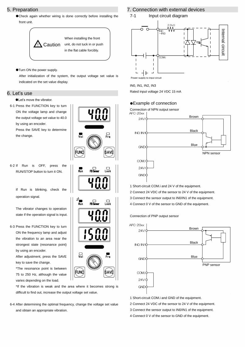
7. Connection with external devices 7-1 Input circuit diagram
IN0, IN1, IN2, IN3
Rated input voltage 24 VDC 15 mA
Example of connection
Connection of NPN output sensor
1 Short-circuit COM.i and 24 V of the equipment.
2 Connect 24 VDC of the sensor to 24 V of the equipment.
3 Connect the sensor output to IN0/IN1 of the equipment.
4 Connect 0 V of the sensor to GND of the equipment.
Connection of PNP output sensor
1 Short-circuit COM.i and GND of the equipment.
2 Connect 24 VDC of the sensor to 24 V of the equipment.
3 Connect the sensor output to IN0/IN1 of the equipment.
4 Connect 0 V of the sensor to GND of the equipment.
When installing the front
unit, do not tuck in or push
in the flat cable forcibly. △! Caution
Inte
rna
l circ
uit
Power supply to input circuit
NPN sensor
Brown
Black
Blue
PNP sensor
Brown
Black
Blue

Connection of relay
1 Short-circuit COM.i and 24 V of the equipment.
2 Connect the contact point of the relay to GND and IN0/IN1 of the
equipment.
Connection of voltage signals
1 Connect voltage signal + to COM.i of the equipment.
2 Connect voltage signal - to IN0/IN1 of the equipment.
Linkage of controller
The slave unit is operated when the master unit is operated.
1 Short-circuit COM.o and GND of the master unit.
2 Short-circuit COM.i and 24 V of the slave unit.
3 Connect OUT0 of the master unit to IN0 of the slave unit.
4 Connect GND of the master unit to GND of the slave unit.
*Full sensor, etc. can be connected to IN1 of the slave unit.
*When connecting a sensor to IN1 of the slave unit, set the advanced
setting to “nor.” If connection is not done, set the advanced setting to “inv”.
7-2 Terminals for IN0/IN1 operation signals
Operation/stop of the vibrator can be done by input to IN0 or IN1.
*Operation/stop logics for the input signal can be changed by the
advanced setting.
*Operation/stop of the vibrator can be controlled by setting ON/OFF delay
timer for the input signal by the advanced setting.
7-3 Input terminal for switching IN2/IN3 pattern No.
The amplitude setting can be switched by input to IN2 or IN3.
How to use
Select “Pt” in “input terminal detailed setting” for the advanced setting.
Four patterns of voltage and frequency can be set for input to IN2 or IN3.
*Currently used setting No. is displayed in “display of currently used
extensions” in the basic setting.
Set No. Pt1 Pt2 Pt3 Pt4
IN2 OFF ON OFF ON
IN3 OFF OFF ON ON
7-4 B analog input connector
The output voltage set value for AFC-20HG can be changed by analog
voltage signal connected to the connector.
[1] Analog voltage input
[2] Common terminal
Molex 5267-02A connector pin layout
Applicable housing Molex 5264-02
Applicable terminal Molex 5263
Wiring of analog voltage input
How to use
Select “AnLG” in “input terminal detailed setting” for the advanced setting.
Master unit Slave unit
Inte
rna
l circ
uit
Voltage output
Shield
Contact point

7-5 A feedback sensor connector
The vibrator is operated at a constant amplitude using the feedback sensor
connected to the connector.
Special feedback sensor PHA-03-C15 (1.5 m)
PHA-03-C35 (3.5 m)
Sensor connection cable PHA-03-CC (0.5 m)
When the feedback sensor is installed to the controller, state indicator FB
sensor on the operation panel blinks.
When the SAVE key is held down while the vibrator is running and FB
sensor is blinking, operation lock is activated and feedback operation is
started.
State indicator FB sensor is ON during feedback operation.
During feedback operation, the voltage set value is changed automatically
by the controller to maintain the amplitude at a certain level in line with the
vibrator load.
Normal operation Feedback operation
When the SAVE key is held down during feedback operation, operation
lock is canceled and normal operation is started.
7-6 Output circuit diagram
OUT0, OUT1, OUT2, OUT3
Rated load 30 VDC 100 mA
Example of connection
Connection of electromagnetic valve load, etc. to the output (NPN)
1 Short-circuit COM.o and 24 V of the equipment.
2 Connect the load to 24 V and OUT1 of the equipment.
Connection of electromagnetic valve load, etc. to the output (PNP)
1 Short-circuit COM.o and 24 V of the equipment.
2 Connect the load to 24 V and OUT1 of the equipment.
7-7 OUT0/OUT1 operation synchronization output
terminal
Load connected to the terminal can be driven in synchronization with
vibrator operation.
*Logic of the output signal can be changed by the advanced setting.
*Stop can be delayed if OFF delay timer is set for the output signal by the
advanced setting (OUT1 only).
7-8 OUT2 workpiece shortage signal output
terminal
The signal is output when shortage of workpieces in the parts feeder is
detected by the full sensor.
*Logic of the output signal can be changed by the advanced setting.
*The function is for AFC-20HG only.
7-9 OUT3 alarm signal output terminal
Responding to controller errors, error indications are displayed on the set
value display and alarm signals are output.
Error indication
“Err2” Overcurrent is flowing to the output to the vibrator.
“Err3” Signals are not input from the feedback sensor.
*In case of errors, remove the cause and then turn ON the power supply to
the controller.
Inte
rna
l circ
uit
Load
Load

8. Setting change 8-1 Basic setting
Voltage setting
When the voltage lamp (Vol LED) is ON,
the voltage set value is displayed on the
set value display.
The values are changed with the encoder.
The set value display blinks while the
value is changed.
Save the setting by pressing the SAVE
key after change.
*Values cannot be changed when the
advanced setting “Adv” is “AnLG”.
Frequency setting
When the voltage lamp (Frq LED) is ON,
the frequency set value is displayed on
the set value display.
The values are changed with the encoder.
The set value display blinks while the
value is changed.
Save the setting by pressing the “SAVE”
key after change.
Currently used extensions*1
Currently used extensions are displayed
in the set value display.
Functions selected in advanced setting
are displayed (“oFF”, “Pt”, “AnLG” or
“drum”).
When “oFF” is displayed, basic setting
can be saved in pattern No.
When “Pt” is displayed, the selected
pattern No. is displayed.
Returned to voltage setting
8-2 Advanced setting Press the “FUNC” key on the basic setting screen for 1 second or more.
*Switching to advanced setting is possible only at operation stop (RUN
indicator OFF).
Press the “FUNC” key in the menu for 1 second or more to return to
basic setting.
If the “FUNC” key is pressed on an item to be changed, the value can
be changed with the encoder, and the value can be saved by pressing
the “SAVE” key. (The change is discarded by pressing the “FUNC” key.)
Input signal terminal IN0 setting menu
Items can be selected with the encoder. Switching of input terminal logic
Selected from the left
ON delay timer (T1)*1
Can be set between 0.0 to 10.0 seconds.
OFF delay timer (T2)*1
Can be set between 0.0 to 10.0 seconds.
Input when the input signal is ON.
Input when the input signal is OFF.
Switched to input signal terminal IN1 setting menu
Input signal terminal IN1 setting menu
Items can be selected with the encoder.
Switching of input terminal logic
Selected from the left
ON delay timer (T3)*1
Can be set between 0.0 to 10.0 seconds.
OFF delay timer (T4)*1
Can be set between 0.0 to 10.0 seconds.
Input when the input signal is ON.
Input when the input signal is OFF.
Input signal terminal detailed setting
menu
Items can be selected with the encoder.
Switching of input signal terminal
extensions*1*2
Selected from
the left
Extensions are not used.
Pattern No. switching is enabled.
Input terminal AN is enabled.
Sequence corresponding to
IN0/IN1 is changed.
Output signal terminal OUT0 setting
menu
Items can be selected with the encoder.
Switching of output terminal logic
Can be selected from the left
Output when the vibrator is in
operation
Output when the vibrator is at a
stop
Output signal terminal OUT1 setting
menu
Items can be selected by the encoder
Switching of output terminal logic
Selected from the left
OFF delay timer (T5)
Can be set between 0.0 to 10.0 seconds.
Output when the vibrator is running.
Output when the vibrator is at stop.
Output signal terminal OUT2 setting
menu*1
Items can be selected with the encoder.
Switching of output terminal logic
Selected from the left
ON delay timer (T6)
Can be set between 0.0 to 60.0 seconds.
Output when the alarm is enabled.
Output when the alarm is disabled.
Switched to input signal terminal IN0 setting menu
*1...AFC-20HG function *2...The operation signal can be switched between AND/OR for AFC-20SE.

9. External dimensions
10. Specifications
Model AFC-20HG AFC-20SE Control system D class Amp system Input Voltage 85 VAC to 265 VAC
Frequency 50Hz/60Hz Number of phases 1 Power reception capacity
85 VA
Output Maximum current 200 mA Voltage 0 to 230 V (secondary side of transformer) Frequency 60 to 400 Hz
Additional functions
External control Function to control operation by external signals
Synchronization signal output
Output in synchronization with vibrator operation (2 points)
Workpiece shortage signal
Workpiece shortage signal output from full sensor*1
ON delay Startup delay setting at a stop due to full*1 OFF delay Delay setting for stop due to full at operation
state*1 Constant amplitude function
Constant amplitude control by acceleration sensor (PHA-03)*1
Ambient operating temperature 0 to 40°C (freezing not allowed) Ambient operating humidity 0 to 90% RH (condensation not allowed) Paint color Gray BN-75 (JPMA) Weight of main unit 0.7 Kg
*1 AFC-20HG function
11. Initialization
Data is erased completely and all settings return to initial values if the power supply is
turned ON while pressing the “RUN/STOP” key.
Be sure to prepare needed data in advance.
12. Troubleshooting
Phenomenon Inspection item Reference A. Indicators and lamps
do not turn ON when the power supply is turned ON.
Is the power cable connected correctly?
B. Vibration does not occur (The Run lamp is ON).
Is the output line connected correctly?
C. Vibration does not occur (The Run lamp is OFF.)
Press the RUN/STOP button to switch to the operation state.
D. Vibration does not occur (The Run lamp is blinking)
Check the external operation signal and the full sensor as well as their parameters.
E. The amplitude is not increased when voltage is increased.
Is the frequency adjusted properly?
Isn’t the used load outside the specified range?
Instruction manual for the vibrator
F. The output frequency cannot be adjusted.
Isn’t it locked?
G. The vibration fluctuates.
Is the frequency adjusted properly?
Is the load attached firmly? Is it free from interference with peripheral devices?
Instruction manual for the vibrator
H. Abnormal noise from the controller
Stop using the controller immediately and turn OFF the power supply. Contact the dealer.
I. Abnormal smell from the controller
13. Warranty 1. The warranty period is one year after delivery of the product.
(Operation time per day is counted as 8 hours.)
2. The warranty does not cover the following cases:
a. Failures attributable to disassembly or modification by the
customer
b. Failures that are obviously attributable to erroneous use
c. Failures caused by natural disasters such as fire, earthquake
and flood
d. Failures caused by non-conformity to use conditions, use
methods and precautions written in the instruction manual
3. As for repair for a fee, the fee will be charged upon discussion.
BM172010
Sales Division, BFC Limited
Head office TEL: 0567-56-2550 FAX: 0567-56-2552
Postal code 490-1435, Nishiume 103-1,
Umenogo, Tobishima-mura, Ama-gun, Aichi
Prefecture
Osaka Sales Office TEL: 06-4806-4777 FAX: 06-4806-4778
Postal code 532-0011, Hanahara Daini
Building 702, Nishi-Nakajima 4-11-27,
Yodogawa-ku, Osaka City
BFC Applications, Ltd.
Tokyo Sales Office TEL: 03-5905-7160 FAX: 03-5905-7161
Postal code 178-0063, MB 1F, Higashi-Oizumi
3-42-8, Nerima-ku, Tokyo