pigeon point bmr-ast-atca reference design · electronics protection pigeon point bmr -ast atca...
TRANSCRIPT
Electronics Protection Pigeon Point BMR-AST-ATCA Reference Design Page 1 / 9
PRODUCT BRIEF
Pigeon Point BMR-AST-ATCA Reference Design
Board Management for (Carrier) IPMCs
Within AdvancedTCA®, AdvancedMC® and Custom Derivative Architectures
May 2, 2016 Electronics Protection Pentair Technical Solutions [email protected] www.pigeonpoint.com www.pentairprotect.com
All Pentair brands and logos are the property of Pentair or its affiliated companies worldwide. Pentair reserves the right to change information without prior notification.
Electronics Protection Pigeon Point BMR-AST-ATCA Reference Design Page 2 / 9
The BMR-AST-ATCA design is one of a series of Pigeon Point Board Management Reference (BMR) designs. This member of the series provides an IPM Controller (IPMC) or Carrier IPMC for AdvancedTCA and custom derivative architectures; it is based on the ASPEED AST2500 integrated remote management processor from ASPEED Technology. This design includes support for the advanced remote redirection facilities of the AST2500, which allow remote keyboard, video and mouse (KVM) hardware, as well as remote media, to be used as if it were attached to the local main CPU, potentially greatly simplifying management of large numbers of blade servers that integrate such IPMCs. The subset variant AST2520 is also supported, but without the remote redirection features, since it does not include the necessary hardware. This reference design is delivered in a Pigeon Point Board Management Starter Kit (which is detailed in a separate Product Brief). The kit includes: Schematics for the core of an IPMC based on
an ASPEED 2500 family device, ready to be adapted for your board or other intelligent Field Replaceable Unit (FRU)
Linux-based foundation layer adapted for operation on the ASPEED-based IPMC
Linux-based IPMC application firmware, delivered in source form and with development tools—ready for simple and quick adaptation to your requirements
One-stop support from Pentair experts for schematics, firmware and software used in developing and delivering your Pigeon Point BMR-based IPMC
Complementary support, if needed, from ASPEED Technology for special hardware aspects of applying an AST2500 family device to the specific needs of your board
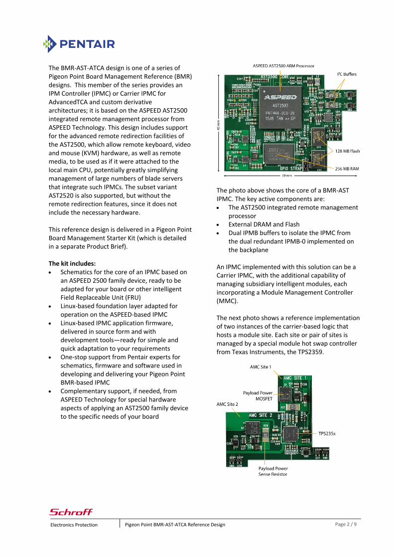
The photo above shows the core of a BMR-AST IPMC. The key active components are: The AST2500 integrated remote management
processor External DRAM and Flash Dual IPMB buffers to isolate the IPMC from
the dual redundant IPMB-0 implemented on the backplane
An IPMC implemented with this solution can be a Carrier IPMC, with the additional capability of managing subsidiary intelligent modules, each incorporating a Module Management Controller (MMC). The next photo shows a reference implementation of two instances of the carrier-based logic that hosts a module site. Each site or pair of sites is managed by a special module hot swap controller from Texas Instruments, the TPS2359.
Electronics Protection Pigeon Point BMR-AST-ATCA Reference Design Page 3 / 9
Specification compliant PICMG 3.0 R3.0 as amended by ECN 3.0-3.0-
001, the AdvancedTCA base specification, plus HPM.1 R1.0, the Firmware Upgrade specification
AMC.0 R2.0, the AdvancedMC base specification
IRTM.0 R1.1, the Intelligent Rear Transition Module base specification
HPM.2 and HPM.3, the LAN-attached IPM Controller and DHCP-assigned Platform Management Parameters specifications (revisions R1.1 and R2.0, respectively)
IPMI v1.5, document revision 1.1 and the relevant subset of IPMI v2.0, document revision 1.1, plus relevant errata
PICMG 3.0, HPM.2/3 and IPMI 2.0 compliance includes support for Internet Protocol version 6 (IPv6)
Compliance tested with Polaris Networks’ ATCA and AMC Testers
Highly adaptable, including for custom, derivative management architectures Usable for blades in bladed systems or for
main system boards in non-bladed systems, such as appliances
Independent of number, size and physical form factors of boards
Board hot swap support available, but need not be used
Interface to higher level management can be based on either I2C or Ethernet, among other options
Allows integration of standards-based boards with proprietary architecture boards within a single bladed system, if desired
Custom derivative management architectures can leverage support for intelligent hot swappable subsidiary modules, with similar potential for integrating both standards-based modules and proprietary modules, if desired
Substantial CPU power can potentially support additional customer management applications
Full support for core IPMC hardware requirements 32-bit ARM11 processor operating at 600 MHz IPMI-aware monitoring of designated AST2500
analog sensors Supports AST2500/2520 variants, with
reduced features for AST2520 Payload voltage monitoring (including 48V
supply) Support for external digital (DS75 or AD7417)
thermal sensors Direct LAN attachment interface or sideband
LAN attachment interface implemented via the standardized Network Controller Sideband Interface (NC-SI) capable of handling IPMI over LAN (including Serial over LAN, HPM.1 upgrades, IPMB trace access and other HPM.2-compliant extensions)
HPM.2-compliant extended inactive state management, including extended management power support
ATCA hot swap interfaces (handle and blue LED)
Dual redundant IPMB-0 Hardware address detection from backplane FRU LED management Payload power supply controls (multiple
voltage levels) Control of E-Keying governed fabric interfaces Optional persistence of above controls across
IPMC resets Optional local System Event Log (SEL) Optional infrastructure for non-intelligent
Rear Transition Modules UART-, LPC/KCS- or LPC/BT-based payload
interface UART-based serial debug interface
Full support for additional core Carrier IPMC hardware requirements Intelligent module (including AMC and IRTM)
payload and management power control / monitoring for each module site, including payload power current measurement
Tight compliance with specification constraints on power control, including fast trip circuits for payload and management power to quickly respond to serious fault conditions, disabling power within 300 ns
Electronics Protection Pigeon Point BMR-AST-ATCA Reference Design Page 4 / 9
Control of fabric E-Keying governed interfaces, both for modules and for on-carrier switches terminating module links.
Control of clock E-Keying governed interfaces, both for modules and for on-carrier clock-related devices
Optional persistence of above controls across Carrier IPMC resets
Management of on-carrier IPMB-L, the primary management communication path with the MMCs of installed modules
Supports a separate logical IPMB-L segment for each module site, so that IPMB-L activity or problems on one leg do not affect the other legs
Optional inclusion of additional AMC carrier-oriented hardware, such as a Base Interface Ethernet switch, in extended power domain, with resulting coverage by extended inactive state management
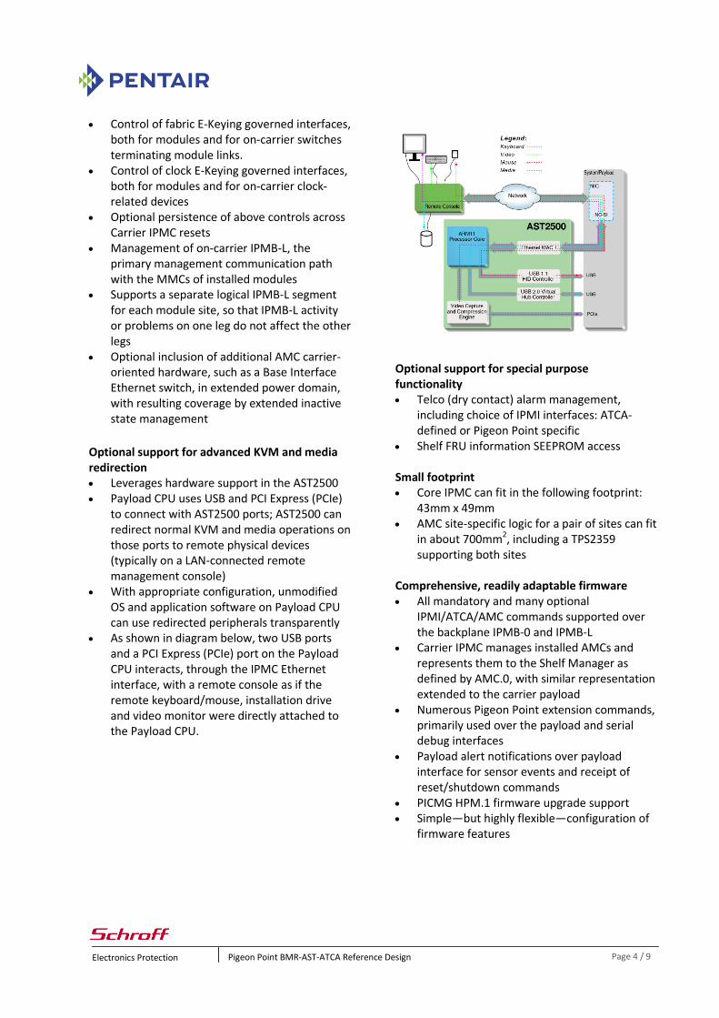
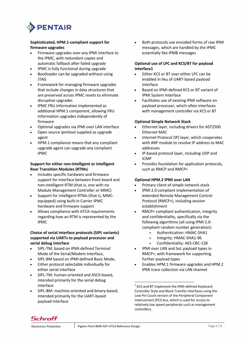
Optional support for advanced KVM and media redirection Leverages hardware support in the AST2500 Payload CPU uses USB and PCI Express (PCIe)
to connect with AST2500 ports; AST2500 can redirect normal KVM and media operations on those ports to remote physical devices (typically on a LAN-connected remote management console)
With appropriate configuration, unmodified OS and application software on Payload CPU can use redirected peripherals transparently
As shown in diagram below, two USB ports and a PCI Express (PCIe) port on the Payload CPU interacts, through the IPMC Ethernet interface, with a remote console as if the remote keyboard/mouse, installation drive and video monitor were directly attached to the Payload CPU.
Optional support for special purpose functionality Telco (dry contact) alarm management,
including choice of IPMI interfaces: ATCA-defined or Pigeon Point specific
Shelf FRU information SEEPROM access Small footprint Core IPMC can fit in the following footprint:
43mm x 49mm AMC site-specific logic for a pair of sites can fit
in about 700mm2, including a TPS2359 supporting both sites
Comprehensive, readily adaptable firmware All mandatory and many optional
IPMI/ATCA/AMC commands supported over the backplane IPMB-0 and IPMB-L
Carrier IPMC manages installed AMCs and represents them to the Shelf Manager as defined by AMC.0, with similar representation extended to the carrier payload
Numerous Pigeon Point extension commands, primarily used over the payload and serial debug interfaces
Payload alert notifications over payload interface for sensor events and receipt of reset/shutdown commands
PICMG HPM.1 firmware upgrade support Simple—but highly flexible—configuration of
firmware features
Electronics Protection Pigeon Point BMR-AST-ATCA Reference Design Page 5 / 9
Sophisticated, HPM.1-compliant support for firmware upgrades Firmware upgrades over any IPMI interface to
the IPMC, with redundant copies and automatic fallback after failed upgrade
IPMC is fully functional during upgrade Bootloader can be upgraded without using
JTAG Framework for managing firmware upgrades
that include changes in data structures that are preserved across IPMC resets to eliminate disruptive upgrades
IPMC FRU Information implemented as additional HPM.1 component, allowing FRU Information upgrades independently of firmware
Optional upgrades via IPMI over LAN interface Open source ipmitool supplied as upgrade
agent HPM.1 compliance means that any compliant
upgrade agent can upgrade any compliant IPMC
Support for either non-intelligent or intelligent Rear Transition Modules (RTMs) Includes specific hardware and firmware
support for interface between front board and non-intelligent RTM (that is, one with no Module Management Controller or MMC)
Support for intelligent RTMs (that is, MMC-equipped) using built-in Carrier IPMC hardware and firmware support
Allows compliance with ATCA requirements regarding how an RTM is represented by the IPMC
Choice of serial interface protocols (SIPL variants) supported via UARTs to payload processor and serial debug interface SIPL-TM, based on IPMI-defined Terminal
Mode of the Serial/Modem Interface, SIPL-BM based on IPMI-defined Basic Mode, Either protocol selectable individually for
either serial interface SIPL-TM: human-oriented and ASCII-based,
intended primarily for the serial debug interface
SIPL-BM: machine-oriented and binary-based, intended primarily for the UART-based payload interface
Both protocols use encoded forms of raw IPMI messages, which are handled by the IPMC essentially like IPMB messages
Optional use of LPC and KCS/BT for payload interface1 Either KCS or BT over either LPC can be
enabled in lieu of UART-based payload interface
Based on IPMI-defined KCS or BT variant of IPMI System Interface
Facilitates use of existing IPMI software on payload processor, which often interfaces with management controller via KCS or BT
Optional Simple Network Stack Ethernet layer, including drivers for AST2500
Ethernet MAC Internet Protocol (IP) layer, which cooperates
with ARP module to resolve IP address to MAC addresses
IP-based protocol layer, including UDP and ICMP
Provides foundation for application protocols, such as RMCP and RMCP+
Optional HPM.2 IPMI over LAN Primary client of simple network stack IPMI 2.0 compliant implementation of
extended Remote Management Control Protocol (RMCP+), including session establishment
RMCP+ compliant authentication, integrity and confidentiality, specifically via the following algorithms (all using IPMI 2.0-compliant random number generation):
Authentication: HMAC-SHA1 Integrity: HMAC-SHA1-96 Confidentiality: AES-CBC-128
IPMI over LAN and SoL payload types in RMCP+, with framework for supporting further payload types
Enables HPM.1 firmware upgrades and HPM.2 IPMI trace collection via LAN channel
1 KCS and BT implement the IPMI-defined Keyboard
Controller Style and Block Transfer interfaces using the Low Pin Count version of the Peripheral Component Interconnect (PCI) bus, which is used for access to relatively low speed peripherals such as management controllers.
Electronics Protection Pigeon Point BMR-AST-ATCA Reference Design Page 6 / 9
Optional HPM.3 IPv4 or IPv6 parameter assignment via direct interaction with DHCPv4 or DHCPv6 server or by Shelf Manager2 or other proxy
Supported LAN interfaces with AST2500 RMII-equipped Ethernet MACs include: NC-SI3, tested with selected Intel NCs,
where LAN connection is typically shared with payload traffic
Direct Ethernet, where the LAN connection is dedicated to management traffic, not shared with the payload
Optional support for HPM.2 extended inactive state management and extended management power Extended inactive state management support,
enables LAN attach facilities (including IPMI over LAN, Serial over LAN and IPMI trace collection) to operate even when IPMC-managed FRU is not active (e.g., set up and enabled before payload is powered for first time), greatly increasing diagnostic visibility benefits
Extended management power support can be implemented in an IPMC if LAN attach configuration requires more than specification-defined 15 W management power.
Shelf Manager queries IPMC for extended management power needs
If needed, Shelf Manager allocates additional power for IPMC, separate from payload power
Example need scenario: extended management power domain (IPMC plus LAN attach Ethernet controller) requires > 15 W of power
2 The Pigeon Point Shelf Manager can be configured to
assign IPv4 address parameters to LAN-attached IPMCs via HPM.3-defined mechanisms. 3 NC-SI is an open specification published by the
Distributed Management Task Force (DMTF, www.dmtf.org) that uses the Reduced Media Independent Interface (RMII) as the physical transport between the network and management controllers.
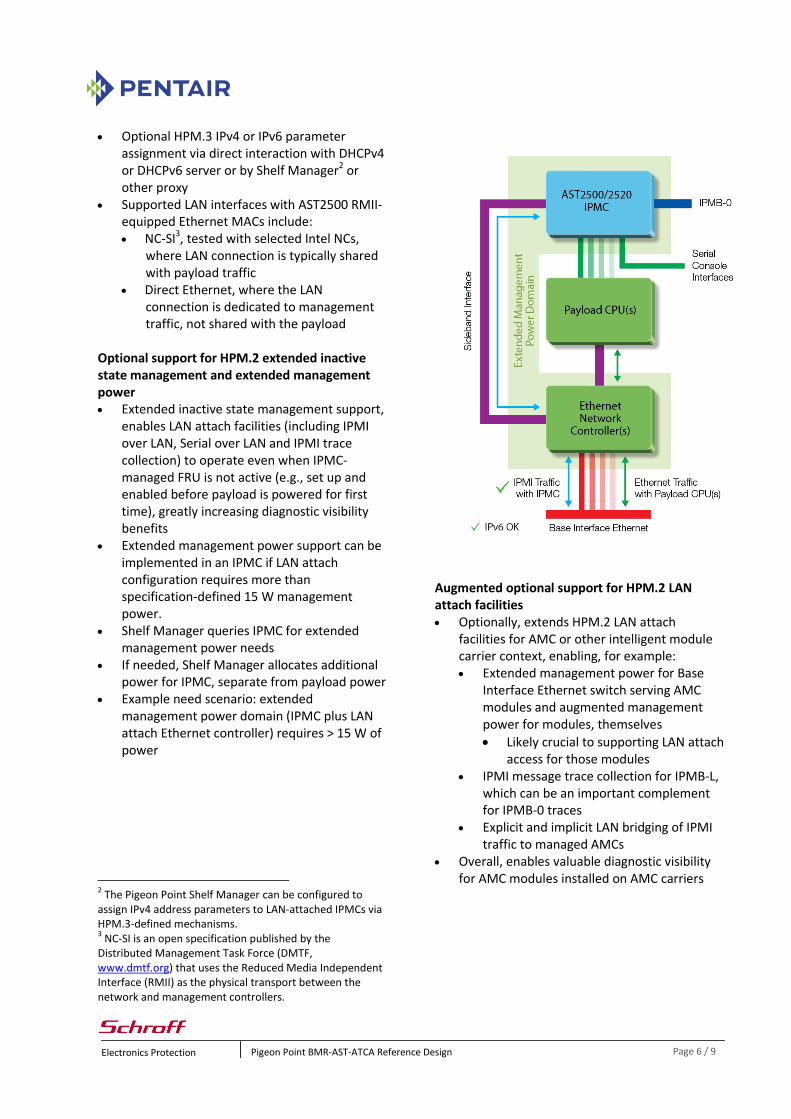
Augmented optional support for HPM.2 LAN attach facilities Optionally, extends HPM.2 LAN attach
facilities for AMC or other intelligent module carrier context, enabling, for example: Extended management power for Base
Interface Ethernet switch serving AMC modules and augmented management power for modules, themselves
Likely crucial to supporting LAN attach access for those modules
IPMI message trace collection for IPMB-L, which can be an important complement for IPMB-0 traces
Explicit and implicit LAN bridging of IPMI traffic to managed AMCs
Overall, enables valuable diagnostic visibility for AMC modules installed on AMC carriers
Electronics Protection Pigeon Point BMR-AST-ATCA Reference Design Page 7 / 9
Optional HPM.2 Serial over LAN (SoL) Uses HPM.2 IPMI over LAN facility to support
Serial over LAN via NC-SI Payload SoL requires separate
physical UART connection between payload and IPMC
SoL for IPMC serial debug interface available, also
HPM.2 SOL extensions allow up to 15 concurrent SOL sessions, each with specific serial ports accessible to the IPMC, user chosen from up to 255 physical on-board serial ports
Supplied open source ipmitool can be used as SoL client
Optional local System Event Log (SEL) Requires SEEPROM storage on board IPMI compliant System Event Log for events
generated on the FRU(s) represented by the IPMC
Can provide a useful historical record of events that have been recorded during operation of a board, perhaps for use in board diagnosis at a maintenance depot
Events are also forwarded to Shelf Manager, as required by ATCA
Optional support for persistent modifications to Sensor Data Records Non-volatile copy of SDR Repository can be
configured in on-board SEEPROM Sensor threshold and hysteresis values can be
configured dynamically via Pigeon Point extension commands, and are thereafter persistent across power cycles and resets of the board
Optional support for payload-controlled sensors Allows sensors that are implemented by the
payload (e.g. an I2C sensor connected to the payload CPU) but exposed by the IPMC as its own
Covers discrete and threshold sensors Optional support for persistent configuration parameters Parameters preserve values across IPMC
power cycles and resets Used for most persistent data, such as serial
port parameters, LAN and SoL parameters Framework for such treatment of other
parameters, including those in custom firmware extensions
Simple, but powerful, firmware configuration mechanisms Configuration variables in a single config.h
source file parameterize and determine inclusion/exclusion of subsystems during firmware image build
Binary configuration files for FRU Information and Sensor Data Records (SDR) merged into firmware image
FRU Information and SDR files produced from textual representations by special supplied compilers
Comprehensive ARM development environment Uses cross GNU C compiler and binary utilities
for ARM x86 Linux-based development environment
included with BMR-AST-ATCA Starter Kit (based on Mentor Graphics Sourcery Code Bench G++ Lite toolchain)
Electronics Protection Pigeon Point BMR-AST-ATCA Reference Design Page 8 / 9
Numerous extensions beyond required IPMI/ATCA/AMC/HPM.x commands and functionality Cold Reset Warm Reset Get Device GUID Get System GUID Get Channel Authentication Capabilities Get Session Challenge Activate Session Set Session Privilege Level Close Session Get Session Info Get/Set Channel Access Get Channel Info Get/Set User Access Get/Set User Name Set User Password Get Sensor Reading Factors Get/Set Sensor Hysteresis Get/Set Sensor Thresholds Get/Set Sensor Event Enable Re-arm Sensor Events Get Sensor Event Status Get Sensor Type Reserve SEL Abort Firmware Upgrade Get Session Handle for Explicit LAN Bridging Rich set of Pigeon Point extension commands All extension commands implemented as
IPMI-compliant OEM messages Get Status Get/Set Serial Interface Properties Get/Set Debug Level Get/Set Hardware Address Get/Set Handle Switch Get/Set Payload Communication Timeout Disable/Enable Payload Control Reset IPMC Hang IPMC4 Bused Resource Control/Status Graceful Reset Diagnostic Interrupt Results Set/Clear Telco Alarm Get Telco Alarm Sensor Number Get/Set Payload Shutdown Timeout Get/Set Local FRU LED State Update Discrete Sensor
4This function is used to test the IPMC watchdog.
Update Threshold Sensor Set EEPROM SDR Data Set EEPROM SDR Hysteresis Set EEPROM SDR Thresholds Reset EEPROM SDR Repository Get/Set GPIO Signal State Reset Non-Volatile Parameters and Reboot Get/Set FRU Info Write-Protect State Get Module State Enable/Disable AMC Site Get/Set PWM DAC Level
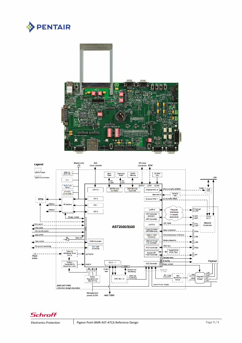
Reference Implementation A bench top implementation called the BMR-AST-PPMC BTR is shown on the next page. In addition to the BMR-AST (Carrier) IPMC core, the board includes implementations of optional IPMC features and numerous LEDs, switches and headers to allow lab experimentation with the behavior of the IPMC. The board also includes one MMC site for testing Carrier IPMC features. Below the photo is a block diagram of a BMR-A2F (Carrier) IPMC.
Electronics Protection Pigeon Point BMR-AST-ATCA Reference Design Page 9 / 9