piksi multi getting started guide -...
TRANSCRIPT

Piksi Multi Getting Started Guide Welcome to the Getting Started Guide for the Swift Navigation Piksi™ Multi RTK GNSS Receiver! This guide is intended for first time Piksi Multi users and provides an overview of how to install the required software, connect to and configure Piksi, and acquire position solutions.
By the end of this guide, you will be able to acquire a fixed RTK solution using two Piksi Multi receivers. The steps in this guide should take you about two hours in total, and the last two steps need to be performed outdoors.
Caution: Piksi Multi uses a powerful processor that can generate a significant amount of heat. Use caution when handling the board, as components may reach upwards of 140° F (60° C).
Install Swift Console and Piksi Multi Drivers This can be done indoors and requires an Internet connection.
The Swift Console is a Graphical User Interface (GUI) program that runs on your computer and allows you to communicate with Piksi Multi. It displays the position and status information and also allows you to change the receiver’s configuration.
Download and Install Swift Console
Windows Download and install the Swift Console Installer for Windows from:
http://swiftnav.com/download/swift_console_windows
Once the download has completed, run the installer.
You may be asked “Do you want to allow this app from an unknown publisher to make changes to your device? ” - If so, click Yes to continue.
After the installer launches, you may choose a location to install to. By default this location is C:\Program FIles (x86)\Swift Navigation\Swift Console\ .
Page 1 Swift Navigation, Inc.

Click the Install . When the installation has completed, click Close . After installation, Swift Console can be launched by double-clicking the icon on the desktop.
Mac OS Download and install the "OS X Console Installer" from the link below:
http://swiftnav.com/download/swift_console_osx
Be sure to drag the Swift Console application into your Applications folder. Later when you try to run the console, launch it from the Swift Console icon located in your Applications Folder.
Linux Please download the latest tar binary distribution of the Swift Console from
http://swiftnav.com/download/swift_console_linux
Extract the tarfile to a location where the current user has read / write permissions.
tar xvfz swift_console_v1.0.A_linux.tar.gz
Next you will need to adjust the permissions on the serial device so it can be accessed from user space. A convenient script ships with the console that adds a udev rule so that all users in the “plugdev” group have access to Swift devices. Here are the instructions for using the script to configure your serial port.
cd swift_console_v1.0.A_linux
sudo ./configure_udev_rules.sh
Lastly, please logout and back in as your user in order for your user’s new “plugdev” group to take effect. When your user has write access to the serial port you should be able to run the console executable from the directory.
cd swift_console_v1.0.A_linux
./console
The provided binary should work on most 64 bit linux distributions and has been tested on Ubuntu 14.04 LTS and Ubuntu 16.06. If you are running a different Linux distribution, or want to run the Swift Console from source, follow the instructions at HOW-TO: Running the Swift Console from source. The source code is available in Swift’s Piksi Tools repository: https://github.com/swift-nav/piksi_tools
Page 2 Swift Navigation, Inc.

Installing the USB to Serial Adapter Drivers An RS-232 serial interface is required to program FreeWave radios used in the Piksi Multi Evaluation Kit and it can be also used to receive and send data to Piksi GNSS receiver. If your PC does not have such interface use USB to Serial adapter included in the kit. Use the instructions below to install the proper device driver for your platform.
Windows Download (http://www.ftdichip.com/Drivers/VCP.htm) and install FTDI's VCP drivers to communicate with Piksi Multi using the provided USB to Serial cable.
Notes:
● Two drivers are available: VCP and D2XX. You only need the VCP driver. Do not install D2XX driver.
Mac OS Install version 2.2.18 of FTDI's VCP driver.
Notes:
● Two drivers are available: VCP and D2XX. You only need the VCP driver. Do not install D2XX driver.
● Piksi requires FTDI driver version 2.2.18, not version 2.3. ● When you run the installer, choose the option for OS X versions 10.4—10.7 (not 10.3). ● If Gatekeeper displays an "unidentified developer" warning and prevents the driver from installing,
you may need to open the driver .dmg file as explained here: https://support.apple.com/kb/PH14369?locale=en_US
After installing the FTDI VCP driver, you must unload the Apple driver and load the FTDI driver by running the following commands from the Terminal application:
sudo kextunload /System/Library/Extensions/IOUSBFamily.kext/Contents/PlugIns/AppleUSBFTDI.kext sudo kextload /System/Library/Extensions/FTDIUSBSerialDriver.kext
After unloading the Apple driver, you might get one of the messages below in your command window.
(kernel) Kext com.apple.driver.AppleUSBFTDI not found for unload request. Failed to unload com.apple.driver.AppleUSBFTDI (libkern/kext) not found.
Or
Can't open CFBundle for /System/Library/Extensions/IOUSBFamily.kext/Contents/PlugIns/AppleUSBFTDI.kext
Ignore those messages and load the FTDI driver. The Swift Console will still work as it should.
Page 3 Swift Navigation, Inc.

Linux Recent versions of Linux (kernel > 3.0) have built-in native kernel support for the FTDI devices and do not require the above drivers.
Connect Piksi Multi Caution : Running the Swift Console on a virtual machine (e.g. VMWare, VirtualBox, Parallels) is strongly discouraged. This is due to imperfections in the USB pass-through functionality, which can lead to symptoms such as freezing during firmware updates and glitches in regular operation.
● Ensure that the Piksi Multi GNSS module is connected to the evaluation board. ○ Be careful when mating Piksi Multi to the evaluation board! Careless mating of the
connectors can damage Piksi Multi and / or the evaluation board. When removing Piksi Multi from the evaluation board, make sure to lift it straight up.
● Connect the AC adapter to the power input on the Evaluation Board ○ Verify the board is receiving power via the LED indicators
Connect to computer via USB to Serial Adapter
After installing the USB to Serial drivers and Swift Console:
● Connect the USB connector on the cable to the computer ● Connect the DE9 connector on the provided USB to Serial cable to RS232 1 on the Evaluation Board ● Start Swift Console ● Select the serial interface from the drop-down menu ● Select the connection baud rate (default: 115200 ) and click OK
Page 4 Swift Navigation, Inc.

Upgrade firmware via Swift Console If the current firmware version does not match the latest, please update to get the most recent features from Swift.
With Piksi Multi connected via USB to Serial adapter (see above) and Swift Console running:
● Connect the included USB drive to your computer ● Click the Firmware Update tab
● Use the folder icon to select the path to the USB drive ● Click Download Latest Firmware button (this will place the newest firmware on the USB drive ) ● Eject the USB drive from your computer ● Connect the USB drive to the USB host port on the Evaluation Board ● Press the Reset button on the Evaluation Board ● When the upgrade completes you'll be prompted to remove the USB drive from the Piksi Evaluation
Board and reboot your Piksi
Validate communications via Status Indicator Once Piksi Multi is connected, and Swift Console is running - verify that the data is flowing properly by checking the status indicator located on the bottom right corner of the Console. If this indicator is solid blue, then communications are working as expected.
Active Inactive
Page 5 Swift Navigation, Inc.
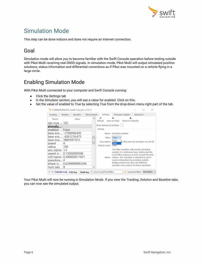
Simulation Mode This step can be done indoors and does not require an Internet connection.
Goal Simulation mode will allow you to become familiar with the Swift Console operation before testing outside with Piksi Multi receiving real GNSS signals. In simulation mode, Piksi Multi will output simulated position solutions, status information and differential corrections as if Piksi was mounted on a vehicle flying in a large circle.
Enabling Simulation Mode With Piksi Multi connected to your computer and Swift Console running:
● Click the Settings tab ● In the Simulator section, you will see a value for enabled . Click on this. ● Set the value of enabled to True by selecting True from the drop-down menu right part of the tab.
Your Piksi Multi will now be running in Simulation Mode. If you view the Tracking , Solution and Baseline tabs, you can now see the simulated output.
Page 6 Swift Navigation, Inc.

Viewing Position Solutions In this simulated set of solutions, the simulated rover is traveling counterclockwise around the simulated base station in a 100 meter radius circle. The way to view these results are through three primary screens in the Swift Console: Tracking , Solution , and Baseline .
Tracking Tab
This tab shows the signals Piksi Multi is tracking. Each signal is represented by a colored line on the graph, and the line's position on the graph represents the strength of the satellite's signal over time.
The x axis is the time and the y axis is Carrier to Noise Ratio (C/No), in dB-Hz, which is the signal strength of the satellite. The most recent time is on the right hand side and the graph scrolls to the left.
Page 7 Swift Navigation, Inc.

Solution Tab
This tab shows Piksi Multi's position solution. The solution type is indicated by color:
● SPP - blue ● DGPS - cyan ● RTK float - purple ● RTK fixed - orange
In simulation mode, Piksi Multi has a fixed RTK solution, which will appear as an orange circle on the display.
Page 8 Swift Navigation, Inc.

Baseline Tab
This tab shows Piksi Multi’s RTK Baseline, a high-precision GPS position solution, with a relative position accuracy of few centimeters. This data visualization will show the base station as a red cross and the rover path in orange or blue.
The Piksi that is connected to the Console is always the Rover and the remote Piksi (not directly connected to this Console) is always the Base . Also, the base is always considered to be at coordinate [0,0,0].
The rover position data is a relative vector between the base and the rover, given as a distance North (graphed on the vertical axis, in meters), East (graphed on the horizontal axis, in meters), and Down (not graphed).
Disabling Simulation Mode
Disable the simulation mode by changing the enabled value back to False on the Settings tab.
Page 9 Swift Navigation, Inc.

Antenna Placement Guidelines Position the antenna as indicated by the blue marker, at a spot with a sky view that is unobstructed above 30 degrees up from the horizon in every direction. For the best results, install the antenna on the top of a tripod (using the included threading adapter) or other stable structure.
Piksi Multi's high-precision, multi-band GNSS antenna is sensitive to its environment. Since Piksi Multi needs to track carrier phase information from GNSS satellites, it is much more sensitive to obstructions than standard consumer GNSS receivers found in, for example, smartphones. Thus, the Piksi Multi antenna must be kept away from any obstructions to its sky view.
● Do place the antenna on a tripod. ● Do not test inside a building. ● Do not place the antenna near buildings. ● Do not place the antenna near trees and other cover. ● Do not stand near the antenna or put your hand over the antenna during testing. ● Do not place an open laptop near the antenna so that the laptop itself is blocking the sky view.
Not indoor Not near buildings Not near trees
Not near people Not near laptop
Page 10 Swift Navigation, Inc.

Standalone GPS Position Note: A Single Point Position solution is a standalone autonomous GPS position solution, with an accuracy of few meters. This is an absolute position and only one Piksi receiver is required to calculate it.
This test must be performed outdoors and does not require an Internet connection.
Goal In this section, you will use one Piksi Multi to display a Single Point Position on the Swift Console.
Hardware Setup ● Place the antenna on a tripod or on other stable structure with an unobstructed sky view - follow the
Antenna Placement Guidelines in section above. ● Connect the short MMCX to SMA adapter cable to the primary antenna connector on the Piksi Multi
GNSS module. ● Connect the SMA to TNC cable to the SMA female connector of the MMCX to SMA cable. ● Connect the TNC connector to the GNSS antenna. ● Connect the USB to Serial adapter cable to the RS232 1 port of the Evaluation Board. ● Connect the opposite end of the USB to Serial cable to your computer. ● Connect your power source to the Evaluation Board - see Powering Piksi Multi . ● Once powered - the LED indicators of Piksi Multi will illuminate.
Running the Swift Console Software ● Launch the Swift Console using as described in the previous section. ● Select the communications device and baud rate for your Piksi Multi from the drop down menu ● Ensure that you have simulation mode disabled, per the instructions from the previous section.
Page 11 Swift Navigation, Inc.

Checking Satellite Signals
Open the Tracking tab. If a satellite has been successfully acquired, it will be assigned to a tracking channel and transitioned to tracking. In the Tracking tab you will see a line added to the plot indicating the signal strength of that satellite. Wait until at least 4 satellites are tracking with signal strengths above 33 dB-Hz.
Controls for the tracking display can be found directly below the graph. The type of signals displayed can be hidden or displayed with the checkboxes in the legend.
Page 12 Swift Navigation, Inc.

Viewing Position Solutions
Once satellite signals are being tracked Piksi Multi will receive the data it needs to compute the position solution. This data is called the ephemeris and it takes approximately 30 seconds to collect. Open the Solution tab and you should see Piksi outputting position solutions represented as a cloud of blue points on the graph. Hint: The POS LED indicator on the Piksi Multi board gives you insight into the position solution status. A blinking POS LED indicates that satellites are being tracked, but no position solution is currently available. A solid orange POS LED indicates a valid position fix.
Page 13 Swift Navigation, Inc.
GPS RTK Position Note: The RTK Position Solution is a high-precision GPS position solution, with an accuracy of a few centimeters. This is a relative position between two Piksi Multi receivers, which are both required to calculate the solution.
To learn more about RTK technology read Understanding Piksi RTK GPS Technology article.
(http://support.swiftnav.com/customer/en/portal/articles/2492803-understanding-gps-rtk-technology)
This test must be performed outdoors and does not require an Internet connection.
Goal In this section, you will setup two Piksi Multi outdoors. One will work as a base station (stationary) and another as a rover (moving). You will be able to display a rover RTK position solution on the Swift Console.
Radio Configuration
In order to achieve an RTK solution, the rover receiver will need to receive correction data from a base station receiver. The Piksi Multi Evaluation Kit includes two radios to provide this link.
The radios must be configured properly before continuing with this guide.
Please follow the Radio Configuration Guide found here: http://support.swiftnav.com/customer/en/portal/articles/2739642-piksi-multi-evaluation-kit---radio-configuration
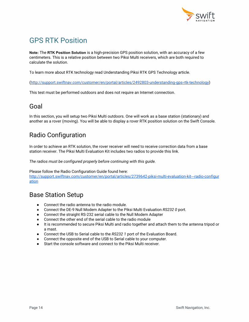
Base Station Setup ● Connect the radio antenna to the radio module. ● Connect the DE-9 Null Modem Adapter to the Piksi Multi Evaluation RS232 0 port. ● Connect the straight RS-232 serial cable to the Null Modem Adapter ● Connect the other end of the serial cable to the radio module ● It is recommended to secure Piksi Multi and radio together and attach them to the antenna tripod or
a mast. ● Connect the USB to Serial cable to the RS232 1 port of the Evaluation Board. ● Connect the opposite end of the USB to Serial cable to your computer. ● Start the console software and connect to the Piksi Multi receiver.
Page 14 Swift Navigation, Inc.

Configuring Base Station Radio Messages In the RTK system, the Base Station transmits its observations to the Rover. The following steps will configure transmission of the base observations and ephemeris data to the rover.
● Open the Settings tab ● Locate the uart0 section ● Set enabled_sbp_messages to 68,72,74,129 ● Click Save to Flash button
The value of the “enabled_sbp_messages” setting in the uart0 section is used to configure which SBP messages are sent over uart0 . Other communications interfaces may also feature this setting, and are configured independently.
Configuring Base Station Location RTK GPS provides a very precise baseline measurement between the base station and the rover. For the rover to provide precise latitude, longitude and altitude, however, the base station must be programmed with its own location. Accuracy of the computed rover's location directly depends on the base station position accuracy. For the best results, position of the base station antenna should be surveyed. To enter the base station location:
● Open Settings tab ● Locate surveyed position section ● Set surveyed lat, surveyed lon, and surveyed alt to their corresponding values ● Select broadcast and change it’s value to True using the drop down menu. ● Click Save to Flash
Page 15 Swift Navigation, Inc.

If the surveyed position is not available, you can the Auto Survey button. This is based on an average of the last 1000 SPP position solutions and therefore not as accurate as a proper survey of the base station location. To use Auto Survey for the base station position:
● Open Settings tab ● Locate surveyed position section ● Select broadcast ● Click the Auto Survey button the upper right hand corner ● Click Auto Survey - note the surveyed lat, surveyed lon, and surveyed alt fields are now populated. ● Select broadcast and change it’s value to True using the drop down menu. ● Click Save to Flash
Finishing Base Station Setup At this point the Piksi Multi base station setup is complete. Close Console, disconnect Piksi Multi from the computer. Leave the base station powered, so that it can continue to provide corrections to the rover.
Page 16 Swift Navigation, Inc.

Rover Setup ● Connect the radio antenna to the radio module. ● Connect the DE-9 Null Modem Adapter to the Piksi Multi Evaluation RS232 0 port. ● Connect the RS232 straight serial cable to the Null Modem Adapter ● Connect the other end of the serial cable to the radio module ● Secure the GNSS antenna to a monopod or on other structure with an unobstructed sky view (follow
the Antenna Placement Guidelines in section above ). ● Connect the short MMCX to SMA adapter cable to the primary antenna connector on the Piksi Multi
GNSS module. ● Connect the SMA to TNC cable to the SMA female connector of the MMCX to SMA cable. ● Connect the TNC connector to the GNSS antenna. ● Connect the USB to Serial cable to the RS232 1 port of the Evaluation Board. ● Connect the opposite end of the USB to Serial cable to your computer. ● Connect your power source (see Powering Piksi Multi ) to the Evaluation Board. ● Once powered - the LED indicators of Piksi Multi will illuminate. ● Start Swift Console and connect to the Piksi Multi receiver.
Checking Rover Satellite Signals
Open Tracking tab. Wait until at least 5 satellites have signal strength above 33 dB-Hz and Piksi computes a Single Point Solution. The POS LED on Piksi Multi will show solid amber once it has a position solution.
Page 17 Swift Navigation, Inc.

Configuring Rover Radio Messages In a typical RTK system, the Rover is only receiving observations (corrections) from the Base Station. The following steps will disable transmission of the rover observations.
● Open Settings tab ● Set uart0 enabled_sbp_messages to 0 ● Click Save to Flash button
Checking Communication Between Piksi Receivers The red LINK LED on Piksi Multi rover board will flash when it correctly receives an observation data from the other Piksi Multi (base station). Open Observations tab. You will see the rover's observations in the upper Local table, and the observations that have been received over the radio from the other Piksi in the lower Remote table. Wait until you can see at least 5 satellites in common between the Base and Rover.
Page 18 Swift Navigation, Inc.
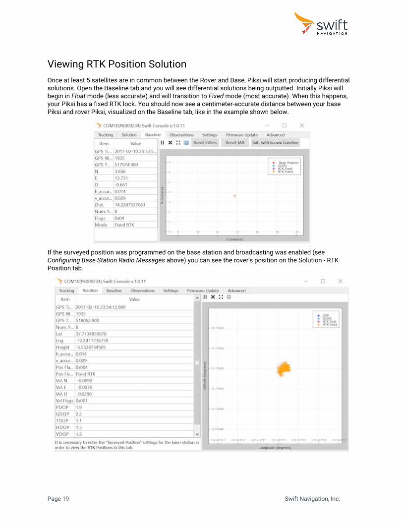
Viewing RTK Position Solution Once at least 5 satellites are in common between the Rover and Base, Piksi will start producing differential solutions. Open the Baseline tab and you will see differential solutions being outputted. Initially Piksi will begin in Float mode (less accurate) and will transition to Fixed mode (most accurate). When this happens, your Piksi has a fixed RTK lock. You should now see a centimeter-accurate distance between your base Piksi and rover Piksi, visualized on the Baseline tab, like in the example shown below.
If the surveyed position was programmed on the base station and broadcasting was enabled (see Configuring Base Station Radio Messages above) you can see the rover's position on the Solution - RTK Position tab.
Page 19 Swift Navigation, Inc.

Congratulations! You now know how to setup and use Piksi Multi. To learn more, visit the Swift Navigation Support Center - http://support.swiftnav.com/.
Page 20 Swift Navigation, Inc.