pilot operating handbook for lsa
TRANSCRIPT

Pilot Operating Handbook for LSA
Edition for GXeLITE Revision GXeLITE-01

GXeLITE Rev. 01
Introduction
Introduction i
Light Sport Aircraft REMOS GX The REMOS GX was manufactured in accordance with the Light Sport Aircraft airworthiness standards and does not conform to standard category airworthiness requirements.
Serial No.:
Built:
Call Sign:
Engine-Type:
Serial No. Engine:
Propeller-Type:
Manufacturer: REMOS Aircraft GmbH Flugzeugbau Franzfelde 31 D-17309 Pasewalk
Phone: +49 3973/225519-0 Fax: +49 3973/225519-99 Internet: www.remos.de
GXeLITE Rev. 01
Introduction
Introduction ii
List of Content and List of Effective Pages This POH consists of the following listed pages and sections. You will find a marking indicating the revision and date of issue at the top border of each page. Insert the latest changed pages.
sect. description pages
0 Introduction i … iv
1 General Information 1.1 … 1.5
2 Operating Limitations 2.1 … 2.20
3 Emergency Procedures 3.1 … 3.7
4 Normal Procedures 4.1 … 4.20
5 Performance 5.1 … 5.7
6 Weight and Balance 6.1 … 6.5
7 Systems 7.1 … 7.27
8 Aircraft Ground Handling and Servicing 8.1 … 8.7
GXeLITE Rev. 01
Introduction
Introduction iii
List of Revisions
sect. description part rev.
0 Introduction GXeLITE 01
1 General Information general 04
2 Operating Limitations GXeLITE 01
3 Emergency Procedures general 03
4 Normal Procedures general 04
5 Performance general 04
6 Weight and Balance general 04
7 Systems GXeLITE 01
8 Aircraft Ground Handling and Servicing
general 04

GXeLITE Rev. 01
Introduction
Introduction iv
Remarks and Alterations Please make a notation below if any changes have been made to this manual or to the plane. This manual is an important document for the pilot in command to ensure safe operation of the aircraft. Therefore it is recommended to keep this Operating Handbook updated with the newest information available. You can get the latest updates of this manual from your dealer or directly from the manufacturer’s homepage.
no. page concern date sign

GXeLITE Rev. 01
Introduction
Introduction v
Views
Face width 6,9 ft
Wingspan 30,6 ft
Length 21,3 ft
Height 7,5 ft
general Rev. 05
1 General Information
General Information 1 - 1
Table of Contents
sect. description page
1.1 Introduction 1-2
1.2 Certification 1-2
1.3 Continued Airworthiness 1-2
1.4 Quick Reference 1-3
1.5 Technical Specifications 1-3
1.6 Engine 1-4
1.7 Propeller 1-5
1.8 ICAO Designator 1-5
1.9 Noise Certification 1-5
general Rev. 05
1 General Information
General Information 1 - 2
1.1 Introduction This Operating Handbook is designed to help enable a safe and successful completion of each flight with the REMOS GX. It provides you with all necessary information for regular maintenance and operation of the aircraft. Therefore we recommend that the pilot keep this Operating Handbook updated with the newest information available. You can get the latest version of this Handbook from your local dealer or directly from the manufacturer’s homepage.
1.2 Certification The REMOS GX was manufactured in accordance with the Light Sport Aircraft airworthiness standards and does not conform to standard category airworthiness requirements.
1.3 Continued Airworthiness Technical publications for continued airworthiness are released on the REMOS website www.remos.com and they may be downloaded free of charge. Bombardier-Rotax releases technical publications on their website www.rotax-aircraft-engines.com from which they may be downloaded free of charge. Documentation update for avionics may be downloaded on www.dynonavionics.com and www.garmin.com. It is the responsibility of the owner/operator of the aircraft to keep the aircraft and its documentation up to date and to comply with all technical publications.

general Rev. 05
1 General Information
General Information 1 - 3
1.4 Quick Reference Type: Full composite carbon fiber aircraft with two seats. Design: High wing design with struts, front mounted engine
and propeller, traditional stabilizer concept, differential ailerons. Electrically operated flaps (0° to 40°), electric elevator trim, three-wheel landing gear with steerable nose wheel. Main gear with hydraulic disc brakes. The cabin is equipped with two seats side by side and can be entered and exited by doors on the left and right side of the fuselage.
Layout: Main components are built in half shells from
composite fiber material, which are bonded together (carbon fiber, Kevlar and glass fiber).
1.5 Technical Specifications wingspan 30 ft 6 in length 21 ft 3 in height 7 ft 5 in wing area 118 sq ft MTOW 1,320 lb wing loading 11 lb /sq ft

general Rev. 05
1 General Information
General Information 1 - 4
1.6 Engine
manufacturer Bombardier-Rotax
engine type 912 UL-S
max. power take-off 73.6 kW / 100 HP max. cont. 69.9 kW / 95 HP
fuel qualities AVGAS, MOGAS or min. AKI 91, ideally free of ethanol
usable fuel quantity 21 US gallons
total fuel quantity 22 US gallons
engine oil synthetic or semi-synthetic
oil rating API-SG or higher
engine oil capacity min. 2.1 qts
max. 3.1 qts
recommended oil AeroShell Sport PLUS 4 10W-40
coolant BASF Glysantin Protect Plus/G48
mixing ratio 1:1 (Glysantin : water)
NOTE
Please refer to REMOS notification NOT-001 and ROTAX SI-912-016/SI-914-019 for further information on fuel containing ethanol and on suitable engine oils. Have a frequent look on www.rotax-engines.com and on www.remos.com for the latest information.

general Rev. 05
1 General Information
General Information 1 - 5
1.7 Propeller
manufacturer
1. FIii. Tonini 2. Woodcomp 3. Sensenich 4. Neuform
type and number of blades 1. GT-169,5/164 2-blade, wood
2. SR38+1 2-blade, wood
3. 2A0R5R70EN 2-blade, composite
4. CR3-65-47-101,6 3-blade, composite
gear ratio 2.43 : 1
slipper clutch optional
1.8 ICAO Designator ICAO Designator: GX (as per ICAO Doc. 8643)
1.9 Noise Certification According to noise requirements for Ultralight aircraft (LS-UL) dated August 1996, the REMOS GX is certified to a noise level of 60 dB (A).

GXeLITE Rev. 01
2 Operating Limitations
Operating Limitations 2 - 1
Table of Contents
sect. description page
2.1 Reference Airspeeds 2-2
2.2 Stalling Speeds at Maximum Takeoff Weight 2-3
2.3 Flap Extended Speed Range 2-3
2.4 Maximum Maneuvering Speed 2-3
2.5 Never Exceed Speed 2-4
2.6 Maximum Wind Velocity for Tie-Down 2-4
2.7 Crosswind and Wind Limitations 2-4
2.8 Maximum Parachute Deploy Airspeed 2-5
2.9 Service Ceiling 2-5
2.10 Load Factors 2-4
2.11 Maximum Structure Temperature 2-5
2.12 Prohibited Maneuvers 2-5
2.13 Permissible Flight Maneuveres 2-5
2.14 Center of Gravity Range 2-6
2.15 Crew 2-6
2.16 Flight Conditions and Minimum Equipment List 2-6
2.17 Engine 2-8
2.18 Airspeed Indicator Range and Markings 2-9
2.19 Placards and Markings 2-10

GXeLITE Rev. 01
2 Operating Limitations
Operating Limitations 2 - 2
2.1 Reference Airspeeds
speed CAS description
VNE Never exceed speed 155 mph (134 kts)
Airspeed which may never be exceeded
VH Maximum speed in level flight
137 mph (119 kts)
Maximum airspeed at maximum continuous power setting
VNO Maximum speed in turbulence
123 mph (107 kts)
Airspeed which shall never be exceeded in gusty weather conditions
VA Maneuvering speed 108 mph (94 kts)
Maximum airspeed for all permissible maneuvers
VFE Speed range flaps fully extended
81 mph (70 kts)
Airspeed which may never be exceeded in flaps down configuration
VAPP Approach airspeed 75 mph (65 kts)
Recommended airspeed for approach with full payload
VX Airspeed for best angle of climb
56 mph (49 kts)
Airspeed for the greatest altitude gain in the shortest horizontal distance
VY Airspeed for best rate of climb
75 mph (65 kts)
Airspeed for the greatest altitude gain in the shortest time
VS1 Minimum airspeed flaps retracted (0°)
51 mph (44 kts)
Minimum permissible airspeed in flaps up configuration
VS0 Minimum airspeed flaps extended (40°)
44 mph (38 kts)
Minimum permissible airspeed in flaps down configuration

GXeLITE Rev. 01
2 Operating Limitations
Operating Limitations 2 - 3
2.2 Stalling Speeds at Maximum Takeoff Weight stall speed with flaps extended VS0 = 44 mph = 38 kts stall speed with flaps retracted VS1 = 51 mph = 44 kts
2.3 Flap Extended Speed Range For deflected flaps following speed restrictions apply as a function of airspeed:
δδδδ VFE
[ deg ] [ mph ] [ kts ]
10 155 134
15 132 115
20 115 100
30 94 81
40 81 70 With flaps set to any deflection the safe load factor is limited to 2.
2.4 Maximum Maneuvering Speed maximum maneuvering speed VA = 108 mph = 94 kts

GXeLITE Rev. 01
2 Operating Limitations
Operating Limitations 2 - 4
2.5 Never Exceed Speed never exceed speed VNE = 155 mph = 134 kts Due do the reduced density of air at altitude, true airspeed is higher than calibrated or indicated airspeed. Therefore VNE is limited to 155 mph = 134 kts true airspeed in order to prevent flutter. With increasing altitude VNE is limited to lower values than indicated by redline according to the following table.
altitude CAS CAS [ ft ] [ mph ] [ kts ]
0 155 135
5,000 147 128
10,000 137 119
15,000 125 110
2.6 Maximum Wind Velocity for Tie-Down max. wind velocity for tie-down in the open VR = 44 mph = 38 kts
2.7 Crosswind and Wind Limitations maximum demonstrated cross wind component for take-off and landing 15 knots The maximum demonstrated crosswind component is not a limitation. The pilot may exceed this demonstrated crosswind component on his or her own discretion. In case the pilot operates the aircraft in crosswind components higher than demonstrated he or she shall be aware of the fact that this flight regime has not been tested. A general wind limitation is not defined for the REMOS GX.

GXeLITE Rev. 01
2 Operating Limitations
Operating Limitations 2 - 5
2.8 Maximum Parachute Deploy Airspeed maximum parachute deploy airspeed 138 mph = 120 kts
2.9 Service Ceiling service ceiling 15,000 ft
2.10 Load Factors safe load factors +4.0 g / -2.0 g With flaps set to any deflection the safe load factor is limited to 2.
2.11 Maximum Structure Temperature max. certified structure temperature 130°F = 54°C
2.12 Prohibited Maneuvers Flight maneuvers not permitted
• aerobatics
• spins
• flight in icing conditions
2.13 Permissible Flight Maneuvers The following maneuvers are permitted
• all non-aerobatic maneuvers, including stalls and departure stalls
• flight with the doors off

GXeLITE Rev. 01
2 Operating Limitations
Operating Limitations 2 - 6
2.14 Weight and Balance
front limit of C.G. 9.6 in (245 mm)
rear limit of C.G. 16.3 in (415 mm)
maximum take-off weight (MTOW) 1,320 lb (600 kg)
typical empty weight 710 lb (322 kg)
max. baggage in baggage compartment 66 lb (30 kg)
max. baggage in each bin 4.4 lb (2 kg)
max. fuel 126 lb (57 kg)
2.15 Crew The REMOS GX is certified to be operated with a minimum of 1 occupant (the pilot in command) and a maximum of 2 occupants. If not otherwise defined by regulations or by the owner/operator, the pilot in command is normally seated on the left.
2.16 Flight Conditions and Minimum Equipment List
operation minimum equipment
Day-VFR as per D-VFR Minimum Equipment List
Night-VFR not approved
IFR in VMC not approved
IFR in IMC not approved
Aerobatics not approved

GXeLITE Rev. 01
2 Operating Limitations
Operating Limitations 2 - 7
D-VFR minimum equipment list
• engine ROTAX 912 UL-S
• silencer
• airbox
• propeller as defined in chapter 2
• carburetor heating system
• compass with compass card
• altimeter
• airspeed indicator
• safety belts
• ELT
• electrical system including circuit breakers
• master and engine kill (ignition) switch
• engine instruments (Dynon FlightDEK D-180)

GXeLITE Rev. 01
2 Operating Limitations
Operating Limitations 2 - 8
2.17 Engine
engine manufacturer Bombardier-Rotax
engine type: 912 UL-S
max. power take-off 73.6 kW / 100 HP
continuous 69.9 kW / 95 HP
max. engine speed take-off 5,800 rpm
continuous 5,500 rpm
idle speed 1,400…1,600 min-1
cylinder head temperature minimum not defined
maximum 275°F (135°C)
oil temperature minimum 120°F (50°C)
maximum 266°F (130°C)
oil pressure minimum 22 psi (1,5 bar)
maximum 73 psi (5,0 bar)
oil pressure below 3,500 rpm minimum 12 psi (0,8 bar)
during cold start maximum 101 psi (7,0 bar)
max. fuel pressure 6 psi (0,4 bar)

GXeLITE Rev. 01
2 Operating Limitations
Operating Limitations 2 - 9
2.18 Airspeed Indicator Range and Markings
Marking CAS Airspeed / Range Description
Red Line, low 44 mph VS0 Minimum airspeed with flaps extended
White Arc 44 to 81 mph VS0 - V FE Airspeed range for flaps extended
Yellow Line 108 mph VA Maximum airspeed for full maneuverability
Green Arc 51 to 123 mph VS1 - V NO Normal use
Yellow Arc 123 to 155 mph VB - V NE Caution in gusty conditions
Red Line, high 155 mph VNE Maximum permissible airspeed
Yellow Triangle 75 mph VAPP Recommended airspeed for approach and best angle of climb

GXeLITE Rev. 01
2 Operating Limitations
Operating Limitations 2 - 10
2.19 Placards and Markings The required placards and markings are created with the following color codes.
Type
Inside
Outside
Information
white lettering on a black background - white framed
black lettering on a white background - black framed
Safety
white lettering on a black background - red framed
red lettering on a white background - red framed
Warning
white lettering on a red background - white framed
red lettering on a white background - red framed
GXeLITE Rev. 01
2 Operating Limitations
Operating Limitations 2 - 11
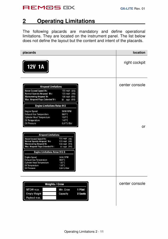
The following placards are mandatory and define operational limitations. They are located on the instrument panel. The list below does not define the layout but the content and intent of the placards.
placards location
right cockpit
center console
or
center console

GXeLITE Rev. 01
2 Operating Limitations
Operating Limitations 2 - 12
placards location
center console
right rocker
panel or on main
spar carrythrough
baggage
compartment
cockpit

GXeLITE Rev. 01
2 Operating Limitations
Operating Limitations 2 - 13
The following safety placard is located on the right side of the panel. This placard is mandatory. The list below does not define the layout but the content and intent of the placards. placard location
right cockpit
The following safety placard is located on the left side of the panel. This placard is mandatory. placard location
left cockpit

GXeLITE Rev. 01
2 Operating Limitations
Operating Limitations 2 - 14
The following information placards and markings are found inside the cabin. Attaching these placards is not mandatory; these placards provide additional information to the pilot. The list below does not define the layout but the content and intent of the placards. placards location
left cockpit
right cockpit

GXeLITE Rev. 01
2 Operating Limitations
Operating Limitations 2 - 15
placards location
center console
center console
switchboard

GXeLITE Rev. 01
2 Operating Limitations
Operating Limitations 2 - 16
placards location
switchboard
switchboard
switchboard
switchboard
optional: constant speed prop
switchboard

GXeLITE Rev. 01
2 Operating Limitations
Operating Limitations 2 - 17
placards location
optional: glider towing aircraft
left cockpit
left rocker panel

GXeLITE Rev. 01
2 Operating Limitations
Operating Limitations 2 - 18
The following information placards and markings are found outside the cabin. Attaching these placards is not mandatory; these placards provide additional information to the pilot. The list below does not define the layout but the content and intent of the placards. placards location
fuel tank filler cap
wheel fairings
static port
GXeLITE Rev. 01
2 Operating Limitations
Operating Limitations 2 - 19
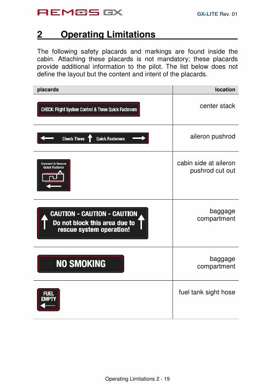
The following safety placards and markings are found inside the cabin. Attaching these placards is not mandatory; these placards provide additional information to the pilot. The list below does not define the layout but the content and intent of the placards. placards location
center stack
aileron pushrod
cabin side at aileron
pushrod cut out
baggage
compartment
baggage
compartment
fuel tank sight hose

GXeLITE Rev. 01
2 Operating Limitations
Operating Limitations 2 - 20
The following safety placards and markings are found outside the cabin. Attaching these placards is not mandatory; these placards provide additional information to the pilot. The list below does not define the layout but the content and intent of the placards. placards location
center of elevator
next to the opening for aileron pushrod,
covered by wing if not folded
center of fixed
surface of elevator, covered if elevator
is installed
wing main bolt

GXeLITE Rev. 01
2 Operating Limitations
Operating Limitations 2 - 21
The following warning placards and markings are found inside the cabin. Attaching these placards is not mandatory; these placards provide additional information to the pilot. The list below does not define the layout but the content and intent of the placards. placards location
center console
door
door
The following warning placards and markings are found outside the cabin. Attaching these placards is not mandatory; these placards provide additional information to the pilot. placards location
recovery system
egress area
strut

general Rev. 05
3 Emergency Procedures
Emergency Procedures 3 - 1
Table of Content
sect. description page
3.1 Definitions 3-2
3.2 Jettison of Doors 3-3
3.3 Spin Recovery 3-3
3.4 Recovery System 3-3
3.5 Voltage Drop 3-4
3.6 Engine Stoppage during Take-Off 3-4
3.7 Engine Stoppage in Flight 3-5
3.8 Carburettor Icing 3-5
3.9 Engine on Fire 3-6
3.10 Emergency Landing on Land 3-6
3.11 Emergency Landing on Water 3-7

general Rev. 05
3 Emergency Procedures
Emergency Procedures 3 - 2
3.1 Definitions
Procedures
are instructions that must be performed in the given sequence, as far as possible without interruption.
Checklists
are lists for items to be checked in the applicable phase of flight (taxi, take-off, climb, etc.). Timing and sequence of the steps to be executed may vary according to the individual flight.
Briefings
are guidelines for upcoming procedures. With the help of briefings, the pilot and passenger should recapitulate those procedures.

general Rev. 05
3 Emergency Procedures
Emergency Procedures 3 - 3
3.2 Jettison of Doors Procedure
1. door lock OPEN
2. hinge pin PULL
3. door JETTISON
3.3 Spin Recovery Procedure
1. control stick NEUTRAL
2. rudder OPPOSITE SPIN DIRECTION
3. after stopping of rotation RECOVER
3.4 Recovery System Procedure
1. engine STOP
2. recovery system RELEASE
3. fuel valve CLOSE
4. declare emergency MAYDAY MAYDAY MAYDAY
5. master switch OFF
6. safety belts TIGHTEN

general Rev. 05
3 Emergency Procedures
Emergency Procedures 3 - 4
3.5 Voltage Drop Procedure
1. engine speed MORE THAN 4.000 RPM
2. non essential systems OFF
3. land on appropriate airfield
NOTE
During day VFR Operations, nonessential systems are all systems except for the radio and intercom. During night VFR or IFR operations, essential systems also include transponder, areal navigation (GPS or SL30 and HS34), instrument lights, position lights, ACL and the artificial horizon (also applicable are Dynon D-100 or D-180 instead of the artificial horizon).
3.6 Engine Stoppage during Take-Off Procedure
during take-off run (aborted take-off)
1. engine speed IDLE
2. brakes AS REQUIRED
3. engine OFF
during climb out (altitude below 500ft)
1. AVIATE – NAVIGATE – COMMUNICATE
2. engine speed IDLE
3. engine OFF
4. fuel valve CLOSE
5. declare emergency MAYDAY MAYDAY MAYDAY
6. master switch OFF
7. safety belts TIGHTEN
8. emergency landing APPROPRIATE TERRAIN
NOTE No course deviations should be made in excesss of 30° to the left or right. Do not return to the airfield.

general Rev. 05
3 Emergency Procedures
Emergency Procedures 3 - 5
3.7 Engine Stoppage in Flight Procedure
case 1: altitude not enough for engine re-start
1. AVIATE – NAVIGATE – COMMUNICATE
2. landing site IDENTIFY
3. engine OFF
4. fuel valve CLOSE
5. declare emergency MAYDAY MAYDAY MAYDAY
6. master switch OFF
7. safety belts TIGHTEN
8. emergency landing APPROPRIATE TERRAIN
case 2: altitude sufficient for engine re-start
1. AVIATE – NAVIGATE – COMMUNICATE
2. landing site IDENTIFY
3. carburetor heat PULL
4. electric fuel pump ON
5. choke OFF
6. starter ENGAGE
7. if engine does not start continue with case 1
8. if engine starts, continue flight and land at the nearest
appropriate airfield to determine the reason for engine failure
3.8 Carburetor Icing Procedure
1. carburetor heat PULL
2. electric fuel pump ON
3. power setting FULL POWER

general Rev. 05
3 Emergency Procedures
Emergency Procedures 3 - 6
3.9 ENGINE ON FIRE Procedure
1. AVIATE – NAVIGATE – COMMUNICATE
2. landing site IDENTIFY
3. fuel valve CLOSE
4. carburetor heat PULL
5. electric fuel pump OFF
6. power setting FULL until ENGINE STOPS
7. declare emergency MAYDAY MAYDAY MAYDAY
8. master switch OFF
9. slip AS REQUIRED
10. safety belts TIGHTEN
11. emergency landing APPROPRIATE TERRAIN
NOTE Never release the recovery system in case of fire.
3.10 Emergency Landing on Land Procedure
1. AVIATE – NAVIGATE – COMMUNICATE
2. landing site IDENTIFY
3. direction of wind IDENTIFY
4. approach airspeed VAPP = 75 mph = 65 kts
5. max. flap speed VFE = 80 mph = 70 kts
6. flaps DOWN
7. trim AS REQUIRED
8. declare emergency MAYDAY MAYDAY MAYDAY
9. master switch OFF
10. safety belts TIGHTEN
11. landing direction INTO THE WIND
or UPHILL
12. touchdown with full elevator on main wheels first
13. after landing, release safety belts and vacate aircraft

general Rev. 05
3 Emergency Procedures
Emergency Procedures 3 - 7
3.11 Emergency Landing on Water Procedure
1. AVIATE – NAVIGATE – COMMUNICATE
2. direction of wind IDENTIFY
3. approach airspeed VAPP = 75 mph = 65 kts
4. max. flap speed VFE = 80 mph = 70 kts
5. flaps DOWN
6. trim AS REQUIRED
7. declare emergency MAYDAY MAYDAY MAYDAY
8. master switch OFF
9. safety belts TIGHTEN
10. doors JETTISON
11. touchdown with full elevator on water surface
12. after landing release safety belts and vacate aircraft
general Rev. 05
4 Normal Procedures
Normal Procedures 4 - 1
Table of Content
sect. description page
4.1 Definitions 4-2
4.2 Fuel Draining 4-3
4.3 Preflight Check 4-4
4.4 Before Start-Up 4-7
4.5 Engine Start 4-7
4.6 After Start-Up 4-8
4.7 Engine Run Up 4-8
4.8 Taxi 4-9
4.9 Departure 4-9
4.10 Take-Off 4-10
4.11 Best Angle of Climb Speed (VX) 4-12
4.12 Best Rate of Climb Speed (VY) 4-12
4.13 Cruise 4-13
4.14 Flying in Rain 4-14
4.15 Flying Without Doors 4-14
4.16 Recovery from Stall 4-15
4.17 Descent 4-15
4.18 Approach 4-16
4.19 Landing 4-17
4.20 Balked Landing 4-19
4.21 After Landing 4-19
4.22 Shutdown 4-19

general Rev. 05
4 Normal Procedures
Normal Procedures 4 - 2
4.1 Definitions
Procedures
are instructions that must be performed in the given sequence, as far as possible without interruption.
Checklists
are lists for items to be checked in the apropriate phase of flight (taxi, take-off, climb, etc.). Timing and sequence of the steps to be executed may vary according to the individual flight.
Briefings
are guidelines for upcoming procedures. With the help of briefings, the pilot and passenger should recapitulate those procedures.

general Rev. 05
4 Normal Procedures
Normal Procedures 4 - 3
4.2 Fuel Draining Procedure Since auto fuel contains a significant amount of ethanol nowadays, draining of the fuel system is more and more important. Draining of the aircraft must be performed before moving the aircraft at all. After re-fueling the aircraft, draining is also required. Give the fuel several minutes to rest after filling it up and do not move the aircraft prior to draining. The drainer is located underneath the belly, just behind the main landing gear. From the outside only a plastic hose with 0.5 in diameter is visible. To drain the fuel tank, press on the plastic hose. Capture the released fuel and analyze it for water. If AVGAS or MOGAS is used, water will clearly deposit underneath the fuel. Continue draining until no more water can be detected. In the case of auto fuel containing ethanol, water can be absorbed by the fuel up to a certain amount, so no water will be detected during draining. If the fuel looks like a milky dispersion, the fuel is saturated with water. In this case dump all of the fuel, do not use this fuel for flying! After dumping fuel, fill up the fuel tank completely with fuel without ethanol. To dump fuel, press in the plastic drainer hose and turn it counter-clockwise (as seen from bottom) about ¼ of a turn. To close the drainer, turn the plastic hose back. Be sure the drainer is properly closed. If dust or dirt particles get inside the drainer, the drainer will not close properly. In this case, open the drainer again to clean the drainer. When draining the aircraft take care that no fuel contaminates the environment. Dispose of drained or dumped fuel in an environmental correct manner. For further information about fuel containing ethanol please refer to the REMOS Notification NOT-001-ethanol-fuel.

general Rev. 05
4 Normal Procedures
Normal Procedures 4 - 4
4.3 Preflight Check Checklist
Checks outside the aircraft
1. fuel system drained before moving the aircraft at all
2. engine oil level (between min. and max. markings)
3. level of engine coolant (between min. and max. markings)
4. cowling is closed and properly secured
5. propeller has no damage or wear
6. nose gear and wheel/tire have no damage or wear, air pressure is
correct and suspension is free
7. static port is clean
8. main wing bolt properly secured with Fokker needle
9. pitot tube is clean and properly fixed
10. wingtip and cover glass are securely mounted and not damaged
11. aileron, linkage and hinges have free travel and no damage,
counterweights are securely fixed
12. upper wing strut attachment is secured
13. flap, linkage and hinges have no damage, rubber stops (flutter
damper) on outer hinges are in place
14. lower wing strut attachment is secured
15. belly top antennas are securely mounted and free of damage
16. left main gear and wheel/tire have no damage or wear, air pressure
is correct and suspension is free
17. cover of ejection opening has no damage
18. top antennas are securely mounted and free of damage
19. fuselage has no damage
20. horizontal tail, elevator, linkage and hinges have free travel and no
damage
21. trim actuator linkage securely mounted and not damaged
22. elevator quick-fastener is securely locked
23. rudder linkage and hinges have free travel and no damage
24. horizontal tail attachment bolts are secured
25. horizontal tail, elevator, linkage and hinges have free travel and no
damage
26. fuselage has no damage

general Rev. 05
4 Normal Procedures
Normal Procedures 4 - 5
27. right main gear and wheel/tire have no damage or wear, air pressure
is correct and suspension is free
28. lower wing strut attachment is secured
29. flap, linkage and hinges have no damage, rubber stops (flutter
damper) on outer hinges are in place
30. upper wing strut attachment is secured
31. aileron, linkage and hinges have free travel and no damage ,
counterweights are securely fixed
32. wingtip and cover glass are securely mounted and not damaged
33. landing light glass is not damaged
34. static port is clean
35. main wing bolt properly secured with Fokker needle It is suggested to perform the outside check according to the following flow diagram:
Insecurely connected, improper operation of control surfaces or insecurely locked fasteners will lead to loss of control of the aircraft!!
Checks inside the aircraft
1
9
11
12
13
14,15,16
17,18,19
2,3,4,5,6
10
22,23 24,25 20,21
26
27,28
29
30
31
32 33
34,35 7,8

general Rev. 05
4 Normal Procedures
Normal Procedures 4 - 6
1. aileron quick-fasteners are securely locked
2. enough fuel on board for the flight 3. both seats are properly secured in intended position 4. both doors can be locked 5. check proper functioning of the flap drive and gauge
Insecurely connected, improper operation of control surfaces or insecurely locked fasteners will lead to loss of control of the aircraft!!

general Rev. 05
4 Normal Procedures
Normal Procedures 4 - 7
4.4 Before Start-Up Checkliste
1. doors LOCKED
2. safety belts FASTENED
3. parking brake SET
4. recovery system ARMED
5. fuel valve OPEN
4.5 Engine Start Procedure
cold engine
1. master switch ON
2. anti-collision-light (ACL) ON
3. oil cooler flap CLOSED
4. electric fuel pump ON
5. engine power CRACKED OPEN
6. choke PULL
7. propeller FREE
8. starter ENGAGE max.10 sec.
warm engine
1. master switch ON
2. anti-collision-light (ACL) ON
3. oil cooler flap AS REQUIRED
4. electric fuel pump ON
5. engine power CRACKED OPEN
6. choke OFF
7. propeller FREE
8. starter ENGAGE max.10 sec.
NOTE
Do not hold the key in the “START” position for more than 10 seconds, in order to avoid overheating the starter. If the engine does not start, release the key to position "0", wait 2 minutes and repeat the procedure.

general Rev. 05
4 Normal Procedures
Normal Procedures 4 - 8
4.6 After Start-Up Procedure
9. engine has started STARTER DISENGAGE
10. choke OFF
11. oil pressure OK
12. position-lights ON
13. avionics switch ON
14. intercom ON
15. radios ON and FREQUENCY SET
16. transponder AS REQUIRED
17. electric fuel pump OFF
18. engine speed for warm-up 2,500 rpm
NOTE
By having the electric fuel pump switched off after starting the engine, only the mechanical pump is providing the engine with fuel. Make sure that the engine is running without the electric pump for at least two minutes. In that time, the engine burns all fuel in the fuel system behind the mechanical fuel pump. If the engine keeps running, the mechanical fuel pump is operational.
4.7 Engine Run Up Checklist
1. oil temperature min. 50°C / 120°F
2. engine speed 4,000 rpm
3. magneto check max. 300 rpm DROP
4. carburetor heat TEMPERATURE RISES
5. engine speed IDLE
6. electric fuel pump ON

general Rev. 05
4 Normal Procedures
Normal Procedures 4 - 9
4.8 Taxi Procedure
1. landing light RECOMMENDED
2. parking brake RELEASE
3. engine speed AS REQUIRED
4. control on ground VIA PEDALS
5. min. turn radius ca. 20 ft = 7 m
6. braking AS REQUIRED
7. taxi speed APPROPRIATE
4.9 Departure Briefing
1. wind, weather, visibility OK
2. ATIS CHECKED
3. runway CORRECT DIRECTION
4. traffic pattern ALTITUDE and ROUTING
general Rev. 05
4 Normal Procedures
Normal Procedures 4 - 10
4.10 Take-Off Procedure
short field take-off
1. oil cooler flap AS REQUIRED
2. carburetor heat OFF
3. electric fuel pump ON
4. brakes SET
5. flaps UP, ON GRASS 15 deg
6. elevator trim 2/3 UP
7. rudder and aileron NEUTRAL
8. engine power FULL POWER
9. brakes RELEASE
10. rotate and lift-off VX = 56 mph = 49 kts
11. steepest climb VX = 56 mph = 49 kts
12. best climb VY = 75 mph = 65 kts
NOTE
Take-off distances given in chapter 5 have been determined with this procedure. It is required to rotate and lift off the aircraft with significant elevator input. Take care not to stall the aircraft during this maneuver.
NOTE It is recommended to keep the electric fuel pump switched on during the entire flight.
NOTE
Full power engine speed on ground is approx. 4,900 rpm with the Sensenich prop and approx. 5,000 rpm with the Tonini and Neuform props.
NOTE
Take-off with reduced power is possible, though not recommended. No take-off shall be performed with engine speed lower than 4,000 rpm. A drastically reduced take-off performance must be taken into account.

general Rev. 05
4 Normal Procedures
Normal Procedures 4 - 11
comfort take-off
1. oil cooler flap AS REQUIRED
2. carburetor heat OFF
3. electric fuel pump ON
4. flaps UP, ON GRASS 15 deg
5. elevator trim 2/3 UP
6. rudder and aileron NEUTRAL
7. engine power FULL POWER
8. rotate 49 mph = 43 kts
9. lift-off 62 mph = 54 kts
10. best climb VY = 75 mph = 65 kts
NOTE
Take-off distance with this procedure can easily be two times or more longer than the short field take-off, but is much more comfortable.
NOTE It is recommended to keep the electric fuel pump switched on during the entire flight.
NOTE
Full power engine speed in ground is approx. 4,900 rpm with the Sensenich prop and approx. 5,000 rpm with the Tonini and Neuform props.
NOTE
Take-off with reduced power is possible, though not recommended. No take-off shall be performed with engine speed lower than 4,000 rpm. A drastically reduced take-off performance must be taken into account.

general Rev. 05
4 Normal Procedures
Normal Procedures 4 - 12
4.11 Best Angle of Climb Speed (VX) Checklist
1. flaps CLEAN
2. electric fuel pump ON
3. steepest climb VX = 56 mph = 49 kts
4. engine power FULL POWER
5. carburetor heat OFF
6. oil cooler flap AS REQUIRED
7. CHT max. 275°F = 135°C
8. oil temperature 120…266°F = 50…130°C
4.12 Best Rate of Climb Speed (VY) Checklist
1. flaps CLEAN
2. electric fuel pump ON
3. best climb VY = 75 mph = 65 kts
4. engine power FULL POWER
5. carburetor heat OFF
6. oil cooler flap AS REQUIRED
7. CHT max. 275°F = 135°C
8. oil temperature 120…266°F = 50…130°C
general Rev. 05
4 Normal Procedures
Normal Procedures 4 - 13
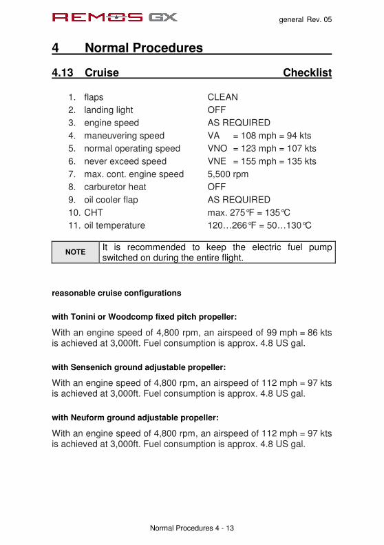
4.13 Cruise Checklist
1. flaps CLEAN
2. landing light OFF
3. engine speed AS REQUIRED
4. maneuvering speed VA = 108 mph = 94 kts
5. normal operating speed VNO = 123 mph = 107 kts
6. never exceed speed VNE = 155 mph = 135 kts
7. max. cont. engine speed 5,500 rpm
8. carburetor heat OFF
9. oil cooler flap AS REQUIRED
10. CHT max. 275°F = 135°C
11. oil temperature 120…266°F = 50…130°C
NOTE It is recommended to keep the electric fuel pump switched on during the entire flight.
reasonable cruise configurations
with Tonini or Woodcomp fixed pitch propeller:
With an engine speed of 4,800 rpm, an airspeed of 99 mph = 86 kts is achieved at 3,000ft. Fuel consumption is approx. 4.8 US gal.
with Sensenich ground adjustable propeller:
With an engine speed of 4,800 rpm, an airspeed of 112 mph = 97 kts is achieved at 3,000ft. Fuel consumption is approx. 4.8 US gal.
with Neuform ground adjustable propeller:
With an engine speed of 4,800 rpm, an airspeed of 112 mph = 97 kts is achieved at 3,000ft. Fuel consumption is approx. 4.8 US gal.
general Rev. 05
4 Normal Procedures
Normal Procedures 4 - 14
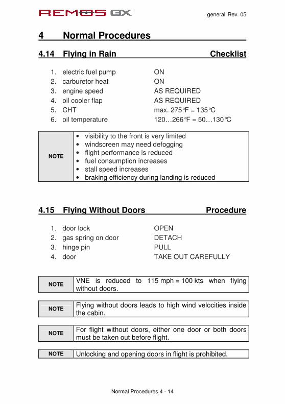
4.14 Flying in Rain Checklist
1. electric fuel pump ON
2. carburetor heat ON
3. engine speed AS REQUIRED
4. oil cooler flap AS REQUIRED
5. CHT max. 275°F = 135°C
6. oil temperature 120…266°F = 50…130°C
NOTE
• visibility to the front is very limited
• windscreen may need defogging
• flight performance is reduced
• fuel consumption increases
• stall speed increases
• braking efficiency during landing is reduced
4.15 Flying Without Doors Procedure
1. door lock OPEN
2. gas spring on door DETACH
3. hinge pin PULL
4. door TAKE OUT CAREFULLY
NOTE VNE is reduced to 115 mph = 100 kts when flying without doors.
NOTE Flying without doors leads to high wind velocities inside the cabin.
NOTE For flight without doors, either one door or both doors must be taken out before flight.
NOTE Unlocking and opening doors in flight is prohibited.

general Rev. 05
4 Normal Procedures
Normal Procedures 4 - 15
4.16 Recovery from Stall Procedure
1. stick back pressure RELEASE
2. rudder OPPOSITE to BANK
3. aileron NEUTRAL
4. engine power AS REQUIRED
4.17 Descent Checklist
1. flaps CLEAN
2. engine speed AS REQUIRED
3. electric fuel pump ON
4. maneuvering speed VA = 108 mph = 94 kts
5. normal operating speed VNO = 123 mph = 107 kts
6. never exceed speed VNE = 155 mph = 135 kts
7. max. cont. engine speed 5,500 rpm
8. carburetor heat RECOMMENDED
9. oil cooler flap AS REQUIRED
10. CHT max. 275°F = 135°C
11. oil temperature 120…266°F = 50…130°C

general Rev. 05
4 Normal Procedures
Normal Procedures 4 - 16
4.18 Approach Briefing
1. wind, weather, visibility OK
2. ATIS CHECKED
3. runway CORRECT DIRECTION
4. traffic pattern ALTITUDE and ROUTING
5. radios ON and FREQUENCY SET
6. transponder AS REQUIRED
7. full flaps BELOW 81 mph = 70kts
8. electric fuel pump ON
9. airspeed in pattern 95…125 mph = 80…110 kts
10. approach airspeed AS RECOMMENDED The approach airspeed marked on the airspeed indicator refers to a max. take-off weight of 1,320lb = 600 kg. The recommended approach airspeed varies with the actual aircraft weight. Please refer to the following table to select the correct approach airspeed.
aircraft weight recommended approach speed
880 lb 58 mph = 50 kts
990 lb 62 mph = 54 kts
1,100 lb 66 mph = 58 kts
1,200 lb 70 mph = 61 kts
1,320 lb 75 mph = 65 kts

general Rev. 05
4 Normal Procedures
Normal Procedures 4 - 17
4.19 Landing Procedure
short field landing
1. approach airspeed VAPP = 65 mph = 57 kts
2. full flaps airspeed VFE = 80 mph = 70 kts
3. flaps DOWN
4. landing light RECOMMENDED
5. engine power AS REQUIRED
6. elevator trim AS REQUIRED
7. electric fuel pump ON
8. carburetor heat RECOMMENDED
9. oil cooler flap AS REQUIRED
10. CHT max. 275°F = 135°C
11. oil temperature 120…266°F = 50…130°C
12. touch down on main wheels first with very little flare.
13. brakes IMMEDIATELY
NOTE
Landing distances given in chapter 5 have been determined with this procedure. Hold the nose landing gear just clear of the ground and touch down with very little flare. Take care not to overload the landing gear during this maneuver.

general Rev. 05
4 Normal Procedures
Normal Procedures 4 - 18
normal landing
1. approach airspeed AS RECOMMENDED
2. full flaps airspeed VFE = 80 mph = 70 kts
3. flaps DOWN
4. landing light RECOMMENDED
5. engine power AS REQUIRED
6. elevator trim AS REQUIRED
7. electric fuel pump ON
8. carburetor heat RECOMMENDED
9. oil cooler flap AS REQUIRED
10. CHT max. 275°F = 135°C
11. oil temperature 120…266°F = 50…130°C
12. touch down on main wheels first with elevator fully held back.
NOTE
Landing distance with this procedure can easily be two times or more longer than the short field landing, but is much more comfortable.
NOTE In high wind or gusty conditions or for training purposes, less than full flap setting or clean flaps permitted.
general Rev. 05
4 Normal Procedures
Normal Procedures 4 - 19
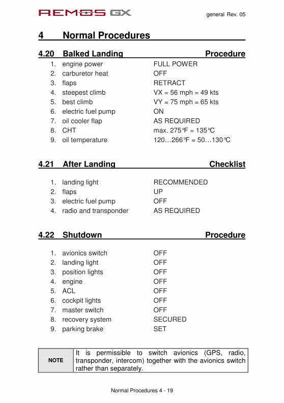
4.20 Balked Landing Procedure
1. engine power FULL POWER
2. carburetor heat OFF
3. flaps RETRACT
4. steepest climb VX = 56 mph = 49 kts
5. best climb VY = 75 mph = 65 kts
6. electric fuel pump ON
7. oil cooler flap AS REQUIRED
8. CHT max. 275°F = 135°C
9. oil temperature 120…266°F = 50…130°C
4.21 After Landing Checklist
1. landing light RECOMMENDED
2. flaps UP
3. electric fuel pump OFF
4. radio and transponder AS REQUIRED
4.22 Shutdown Procedure
1. avionics switch OFF
2. landing light OFF
3. position lights OFF
4. engine OFF
5. ACL OFF
6. cockpit lights OFF
7. master switch OFF
8. recovery system SECURED
9. parking brake SET
NOTE
It is permissible to switch avionics (GPS, radio, transponder, intercom) together with the avionics switch rather than separately.

general Rev. 05
5 Performance
Performance 5 - 1
Table of Contents
sect. description page
5.1 General 5-2
5.2 Take-Off and Landing Distances 5-3
5.3 Rate of Climb 5-4
5.4 Cruise Speed, RPM, Fuel Consumption, Range 5-5
5.5 Low Airspeed and Stall 5-6

general Rev. 05
5 Performance
Performance 5 - 2
5.1 General All flight performance data are given for ISA standard atmosphere at sea level and standard temperature. To determine temperature in relation to ISA conditions please refer to the following chart:
ISA std. Temperature
0
1000
2000
3000
4000
5000
6000
7000
8000
9000
10000
11000
12000
13000
14000
15000
-15 -10 -5 0 5 10 15
temperature [ °C ]
pre
ss
ure
alt
itu
de
[ ft
]
Flight performance can vary significantly due to tolerances, setting of propeller and engine, flight without doors, deviation of temperature and air density from standard ISA conditions, etc. Range applies to the 22 gallon fuel tank system (21 gallons usable) without reserve, within the ICAO standard atmosphere at given altitude.

general Rev. 05
5 Performance
Performance 5 - 3
5.2 Take-Off and Landing Distances
Take-Off Woodcomp or Tonini
Sensenich or Neuform
Take-off roll distance (Flaps 0°)
ft m
n/a 495ft 151m
Take-off air distance (Flaps 0°)
ft m
n/a 226ft 69m
Take-off distance (Flaps 0°)
ft m
n/a 721ft 220m
Take-off roll distance (Flaps 15°)
ft m
580ft 177m
525ft 160m
Take-off air distance (Flaps 15°)
ft m
325ft 99m
200ft 61m
Take-off distance (Flaps 15°)
ft m
905ft 265m
725ft 215m
Landing all propellers
Landing roll distance (Flaps 40°)
ft m
341ft 104m
Landing air distance (Flaps 40°)
ft m
335 102m
Landing distance (Flaps 40°)
ft m
676ft 206m
NOTE
Take-off/landing conditions have been determined at ISA standard conditions at mean sea level and over a virtual 50ft obstacle.
NOTE
Short field procedures apply. Diverting from the short field procedures defined in section 4 will lead to significant longer take-off and landing distances.

general Rev. 05
5 Performance
Performance 5 - 4
Performance data apply under ISA conditions on a dry, hard runway surface. Various circumstances have an effect on take-off and landing performance. According to ICAO-circular 601AN/55/2, it is recommended to use following add-ons on roll- and air distances:
add-ons on take-off roll distance
for dry grass + 20%
for wet grass + 30%
for soft surface + 50%
per 2 knots tailwind component + 10%
per 10 knots headwind component - 10%
for high temperatures above standard + 10% per 10°C
for altitude above sea level (density altitude) + 5% per 1,000 ft
add-ons on take-off air distance
for dirty wings/raindrops + 15%
per 2 knots tailwind component + 10%
per 10 knots headwind component - 10%
for high temperatures above standard + 10% per 10°C
for altitude above sea level (density altitude) + 5% per 1,000 ft
5.3 Rate of Climb
Propeller Woodcomp or Tonini
Sensenich Neuform
best angle of climb
airspeed VX
mph
kts
56
49
56
49
56
49
best rate of climb
airspeed VY
mph
kts
75
65
75
65
75
65
best rate of climb
at MSL fpm 600 710 710
climb is flown with flaps retracted, see section 4

general Rev. 05
5 Performance
Performance 5 - 5
5.4 Cruise Speed, RPM, Fuel Consumption, Range Rotax 912 UL-S, 100 hp engine, Woodcomp or Tonini Fixed Pitch Prop
Engine Speed
Fuel Consumption
True Airspeed
Maximum Endurance
Maximum Range
rpm gph 3,000 ft, mph / kts hr NM
5,400 6.7 113 / 98 3.2 311 5,200 6.0 109 / 95 3.5 332 5,000 5.4 104 / 91 3.9 353 4,800 4.9 100 / 87 4.3 375 4,600 4.4 95 / 83 4.8 401 4,400 3.9 91 / 79 5.4 425 4,200 3.5 86 / 75 6.0 446
Rotax 912 UL-S, 100 hp engine, Sensenich Ground Adjustable Prop
Engine Speed
Fuel Consumption
True Airspeed
Maximum Endurance
Maximum Range
rpm gph 3,000 ft, mph / kts hr NM
5,400 6.7 130 / 113 3.2 362 5,200 6.0 123 / 107 3.5 375 5,000 5.4 117 / 102 3.9 398 4,800 4.9 111 / 97 4.3 417 4,600 4.4 105 / 91 4.8 437 4,400 3.9 98 / 85 5.4 459 4,200 3.5 92 / 80 6.0 480
Rotax 912 UL-S, 100 hp engine, Neuform Ground Adjustable Prop
Engine Speed
Fuel Consumption
True Airspeed
Maximum Endurance
Maximum Range
rpm gph 3,000 ft, mph / kts hr NM
5,400 6.7 130 / 113 3.2 362 5,200 6.0 123 / 107 3.5 375 5,000 5.4 117 / 102 3.9 398 4,800 4.9 111 / 97 4.3 417 4,600 4.4 105 / 91 4.8 437 4,400 3.9 98 / 85 5.4 459 4,200 3.5 92 / 80 6.0 480

general Rev. 05
5 Performance
Performance 5 - 6
5.5 Low Airspeed and Stall If the center of gravity is within the permissible range, the aircraft will be fully controllable until reaching the stall speed. If stall speed is reached, the pilot should lower the nose of the aircraft to re-establish a safe airspeed. level stall
CG at most rearward position (airspeeds at IAS)
Flap Position 0° 15° 30° 40°
Vmin. at idle 51 mph
(44 kts)
47 mph
(41 kts)
45 mph
(39 kts)
44 mph
(38 kts)
Vmin. at full power 50 mph
(43 kts)
47 mph
(41 kts)
44 mph
(38 kts)
44 mph
(38 kts)
CG at most forward position (airspeeds at IAS)
Flap Position 0° 15° 30° 40°
Vmin. at idle 50 mph
(43 kts)
46 mph
(40 kts)
44 mph
(38 kts)
43 mph
(37 kts)
Vmin. at full power 47 mph
(41 kts)
46 mph
(40 kts)
44 mph
(38 kts)
43 mph
(37 kts)

general Rev. 05
5 Performance
Performance 5 - 7
stall in turns
CG at most rearward position (airspeeds at IAS), 30° bank
Flap Position 0° 15° 30° 40°
Vmin. at idle 51 mph
(44 kts)
47 mph
(41 kts)
44 mph
(38 kts)
44 mph
(38 kts)
Vmin. at full power 53 mph
(46 kts)
47 mph
(41 kts)
44 mph
(38 kts)
44 mph
(38 kts)
CG at most forward position (airspeeds at IAS), 30° bank
Flap Position 0° 15° 30° 40°
Vmin. at idle 53 mph
(46 kts)
49 mph
(42 kts)
45 mph
(39 kts)
44 mph
(38 kts)
Vmin. at full power 54 mph
(47 kts)
50 mph
(43 kts)
46 mph
(40 kts)
44 mph
(38 kts)
As the aircraft approaches the stall speed, this will be indicated by slight aerodynamic buffeting. The stall speed is reached when the aircraft becomes unstable in flight, but should still be controllable. It is also possible to perform a stall while in a turn, but the stall speed will increase (see table above).

general Rev. 04
6 Weight-and-Balance-Information
Weight and Balance Information 6 - 1
Table of Contents
sect. description page
6.1 Center of Gravity Range and Determination 6-2
6.2 CG-Calculation 6-3
6.3 Calculation Example 6-4
6.4 Aircraft Specific Weights 6-5

general Rev. 04
6 Weight-and-Balance-Information
Weight and Balance Information 6 - 2
6.1 Center of Gravity Range and Determination To determine “CG”, put the aircraft on 3 weighing scales, positioned on a level surface. Before weighing, a level wing main chord has to be established (use pads between main wheels and scale beneath). A check-mark reference point (R.P.) on the leading edge of the left wing, adjacent to the wing root, is provided to ease examination. To level the wing main chord, use a flexible clear hose, filled with water, as a spirit level. The total weight G = G1 + G2, has to be used for calculating “CG”, located at the distance “X” behind R.P.
general Rev. 04
6 Weight-and-Balance-Information
Weight and Balance Information 6 - 3
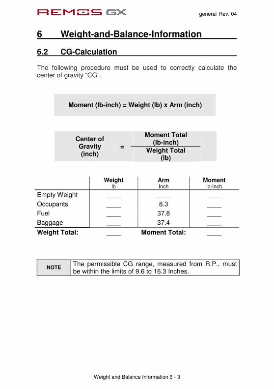
6.2 CG-Calculation The following procedure must be used to correctly calculate the center of gravity “CG”.
Moment (lb-inch) = Weight (lb) x Arm (inch)
Moment Total (lb-inch)
Center of Gravity (inch)
= Weight Total
(lb)
Weight
lb Arm Inch
Moment lb-Inch
Empty Weight ____ ____ ____ Occupants ____ 8.3 ____ Fuel ____ 37.8 ____ Baggage ____ 37.4 ____
Weight Total: ____ Moment Total: ____
NOTE The permissible CG range, measured from R.P., must be within the limits of 9.6 to 16.3 Inches.

general Rev. 04
6 Weight-and-Balance-Information
Weight and Balance Information 6 - 4
6.3 Calculation Example The following example is given to show how to calculate the center of gravity “CG“. Do not use the weights and the empty C.G. in this example for your own flight preparation.
Weight
lb Arm Inch
Moment lb-Inch
Empty Weight 670 12.5 8,375
Occupants 175 8.3 1,453
Fuel 120 37.8 4,536
Baggage 30 37.4 1,122
Weight Total: 995 Moment Total: 15,486
Moment Total (lb-inch)
Center of Gravity (inch)
= Weight Total
(lb)
= 15.6 inch

general Rev. 04
6 Weight-and-Balance-Information
Weight and Balance Information 6 - 5
6.4 Aircraft Specific Weights Below are noted the aircraft specific data. Pilots must use this information to ensure a correct weight and balance calculation prior to every flight. This is essential for safe flight.
empty weight
payload C.G. date of weighing
date of list of equipment
sign

GXeLITE Rev. 01
7 Airplane and Systems Description
Systeme 7 - 1
Table of Contents
sect. description pages
7.1 Cockpit Overview 7-2
7.2 Left Panel – Primary Instruments 7-3
7.3 Motor operation 7-8
7.4 Center Stack 7-9
7.5 Right Panel- Backup and Engine Instruments 7-11
7.6 Circuit Breakers 7-12
7.7 Electrical System 7-14
7.8 Center Console 7-16
7.9 Recovery System 7-17

GXeLITE Rev. 01
7 Airplane and Systems Description
Systeme 7 - 2
7.1 Cockpit Overview Cockpit example
switchboard
oil cowl flap
dual throttle
Radio
Intercom
Transponder
backup Instruments
ELT
circuit breakers

GXeLITE Rev. 01
7 Airplane and Systems Description
Systeme 7 - 3
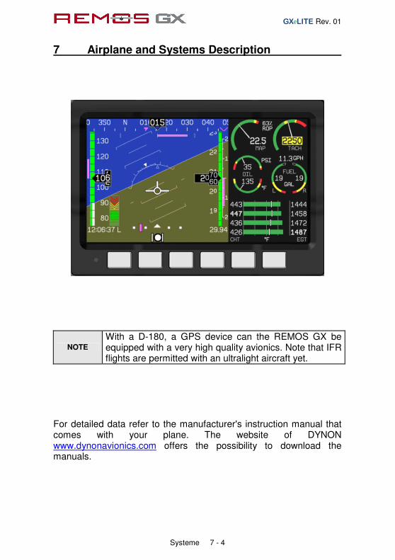
7.2 Left Panel – Primary Instruments Dynon Flight DEK D-180
Instrumentation consists of a DYNON Flight DEK D-180, a BECKER radio AR6201, an optional intercom ps-engineering PM3000 and a BECKER transponder BXP6401.
Primary flight and engine instrumentation is displayed on a DYNON Flight DEK D-180. This is a highly-integrated avionics system, unify-ing an “Electronic Flight Information System” and an “Engine Moni-toring System. This means that primary and secondary flight and navigation instrumentation is displayed on a color display. The fol-lowing functions are guaranteed: Guaranteed functionality includes airspeed indicator, altimeter, verti-cal speed indicator, turn and slip indicator, magnetic compass, artifi-cial horizon, voltmeter, g-meter, engine tachometer, oil pressure, oil temperature, CHT (1), fuel on board, timer.
GXeLITE Rev. 01
7 Airplane and Systems Description
Systeme 7 - 4
NOTE
With a D-180, a GPS device can the REMOS GX be equipped with a very high quality avionics. Note that IFR flights are permitted with an ultralight aircraft yet.
For detailed data refer to the manufacturer's instruction manual that comes with your plane. The website of DYNON www.dynonavionics.com offers the possibility to download the manuals.

GXeLITE Rev. 01
7 Airplane and Systems Description
Systeme 7 - 5
Becker BXP6401
The basic-equipped consists an Transponder. This Transponder is the airborne component of the Air Traffic Control (ATC). It functions in accordance with the secondary radar principle and allows air traffic control to locate, identify and track air craft.
The transponder provides the following features:
• In the selective mode, the Ground Control can interrogate the transponder individually using an ICAO-24-bit address, which is unique to the particular air craft.
• Support of the SI code (Surveillance Identifier)
• Register capability for elementary surveillance (ELS) and enhanced surveillance (EHS)
• Extended squitters transmission For detailed data refer to the manufacturer's instruction manual that comes with your plane. The website of BECKER www.becker-avionics.com offers the possibility to download the manuals.

GXeLITE Rev. 01
7 Airplane and Systems Description
Systeme 7 - 6
Becker AR 6201
The VHF transceiver is designed as a single block unit for usage in cockpit environment of general aviation aircrafts.
The VHF transceiver has an input for both standard and dynamic microphones. For detailed data refer to the manufacturer's instruction manual that comes with your plane. The website of BECKER www.becker-avionics.com offers the possibility to download the manuals.
GXeLITE Rev. 01
7 Airplane and Systems Description
Systeme 7 - 7
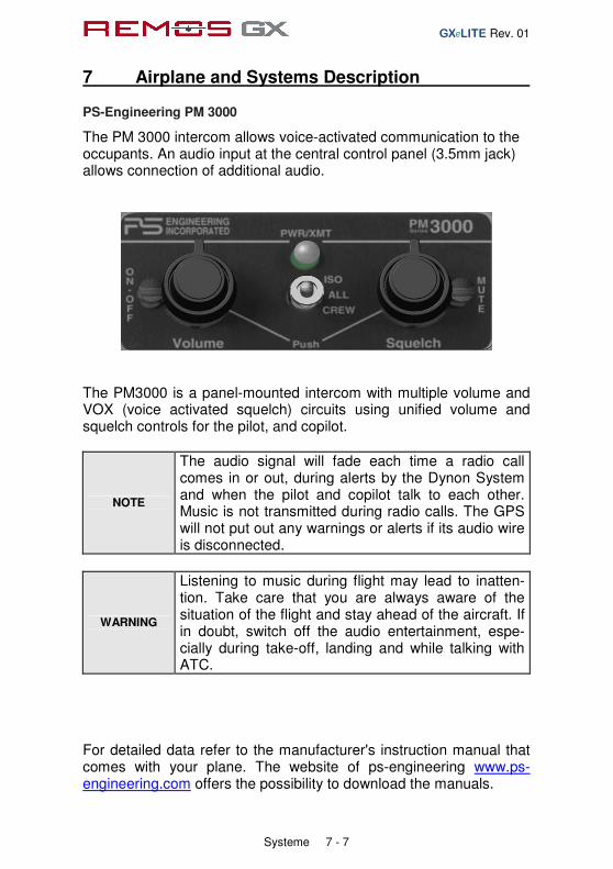
PS-Engineering PM 3000
The PM 3000 intercom allows voice-activated communication to the occupants. An audio input at the central control panel (3.5mm jack) allows connection of additional audio.
The PM3000 is a panel-mounted intercom with multiple volume and VOX (voice activated squelch) circuits using unified volume and squelch controls for the pilot, and copilot.
NOTE
The audio signal will fade each time a radio call comes in or out, during alerts by the Dynon System and when the pilot and copilot talk to each other. Music is not transmitted during radio calls. The GPS will not put out any warnings or alerts if its audio wire is disconnected.
WARNING
Listening to music during flight may lead to inatten-tion. Take care that you are always aware of the situation of the flight and stay ahead of the aircraft. If in doubt, switch off the audio entertainment, espe-cially during take-off, landing and while talking with ATC.
For detailed data refer to the manufacturer's instruction manual that comes with your plane. The website of ps-engineering www.ps-engineering.com offers the possibility to download the manuals.
GXeLITE Rev. 01
7 Airplane and Systems Description
Systeme 7 - 8
7.3 Engine Operation
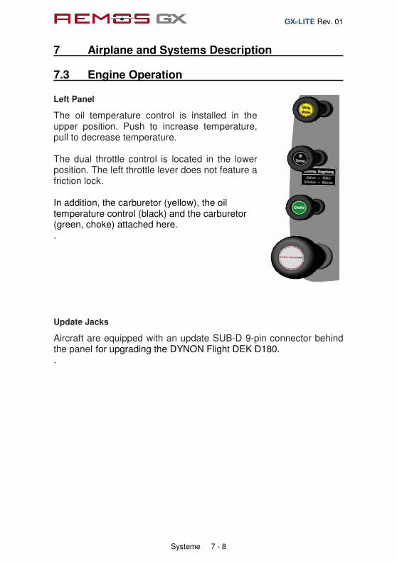
Left Panel
The oil temperature control is installed in the upper position. Push to increase temperature, pull to decrease temperature. The dual throttle control is located in the lower position. The left throttle lever does not feature a friction lock. In addition, the carburetor (yellow), the oil temperature control (black) and the carburetor (green, choke) attached here. . Update Jacks
Aircraft are equipped with an update SUB-D 9-pin connector behind the panel for upgrading the DYNON Flight DEK D180. .

GXeLITE Rev. 01
7 Airplane and Systems Description
Systeme 7 - 9
7.4 Center Stack The avionics include variations depending on the equipment (except in the base configuration) a GPS. As a Garmin GPS are here aera a Garmin 696 or 500, mounted in a frame AirGizmo, or install the Flymap-L with a touch screen (with optional GSM modem for online access to the DWD weather data).

GXeLITE Rev. 01
7 Airplane and Systems Description
Systeme 7 - 10
At the central control panel all controls of the REMOS GX are located. All switches are clearly labeled.
The switch panel incorporates the following:
• Switch for ACL
• Navigation lights
• Switch for landing lights
• Switch for fuel pump
• Position display for electric flaps
• Throttle lever with locking device
• Charging indicator light of the generator
• Master and avionics switches
• Throttle control with friction lock
• Audio connection
GXeLITE Rev. 01
7 Airplane and Systems Description
Systeme 7 - 11
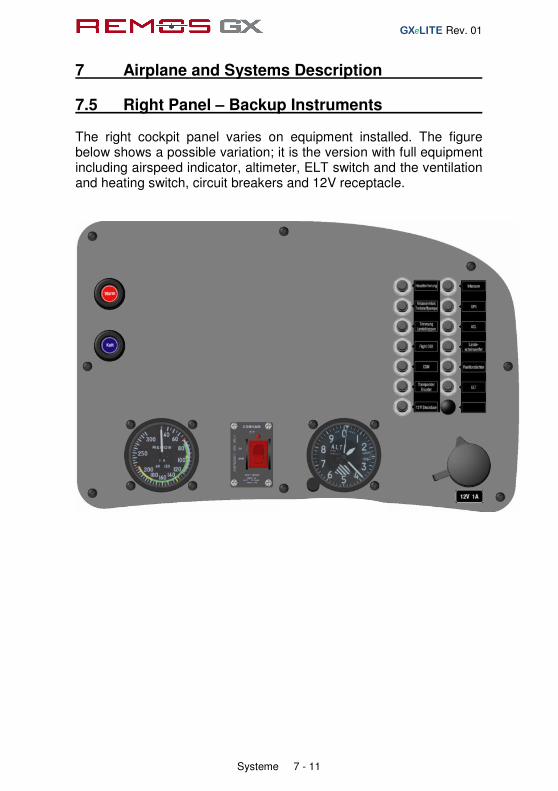
7.5 Right Panel – Backup Instruments The right cockpit panel varies on equipment installed. The figure below shows a possible variation; it is the version with full equipment including airspeed indicator, altimeter, ELT switch and the ventilation and heating switch, circuit breakers and 12V receptacle.

GXeLITE Rev. 01
7 Airplane and Systems Description
Systeme 7 - 12
7.6 Circuit Breakers The electrical systems of the REMOS GX are secured with circuit breakers (CB). The fuse for the charge control check light is located behind the switch panel. In the engine room to find the fuses for the controller, as well as the loading control.
All circuit breakers are labeled; additionally the placard shown below is applied inside the cockpit to give more detailed information. Here you can find detailed information about the rating of each CB.

GXeLITE Rev. 01
7 Airplane and Systems Description
Systeme 7 - 13
If a CB has been tripped, the lip points out of the front side. To reset the CB, push in the lip. To release a CB manually, it must be pulled out of its socket.

GXeLITE Rev. 01
7 Airplane and Systems Description
Systeme 7 - 14
7.7 Electrical System The electrical system of the REMOS GX is powered by an alternator, which is capable of 250W at engine speeds of at least 4,000 RPM. At lower engine speeds the output of the alternator is lower. Below a certain engine speed the alternator is not able to support the power demand for all electrical equipment. The exact engine speed is not easily defined and varies base on the equipment installed. The criti-cal engine speed is around 2,500 RPM. If your REMOS GX is operated in an environment where you have long taxiways or you operate the aircraft a longer time with low RPM, switch off electrical equipment that are not essential in order to con-serve battery power.
NOTE
With engine or when taxiing with low RPM the alternator is definitely not able to cover the electric power con-sumption and the battery will be discharged

GXeLITE Rev. 01
7 Airplane and Systems Description
Systeme 7 - 15
The following table gives an overview of the power consumption of your electrical equipment.
consumer power[ W ] current@ 12V [ A ]
Dynon D180 19 1,5
FlymapL 42 3,5
Garmin GPS696 15 1,1
Garmin aera 500 10 3,6
Becker AR6201 6 1,6
Becker BXP6401 14 0,4
PM3000 10 0,8
ACL (LED) 37 3,1
position lights 12 1,0
landing lights (LED) 24 2,0
Electric fuel pump 20 1,7
Elevator trim 4 0,3
flap drive 25 2,1
12V receptacle 12 1,0
Power shortage makes itself felt primarily by malfunctioning of the transceiver in transmit mode. There is no transmission possible. Other equipment, e.g. the DYNON D180, will display a low voltage warning. To prevent electrical shortage, following procedure is recommended:
• switch off all non-essential electrical loads
• engine speed on ground 2.500RPM
• engine speed in flight 4.200RPM Low temperatures reduce the capacity to increase the on-board battery and its internal resistance. This may cause some trouble in the cold season. If the aircraft is not operated in winter time REMOS recommends storing the battery in a warm and dry place.
GXeLITE Rev. 01
7 Airplane and Systems Description
Systeme 7 - 16
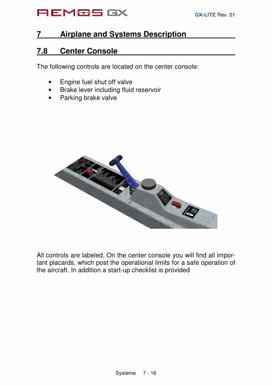
7.8 Center Console The following controls are located on the center console:
• Engine fuel shut off valve • Brake lever including fluid reservoir
• Parking brake valve
All controls are labeled. On the center console you will find all impor-tant placards, which post the operational limits for a safe operation of the aircraft. In addition a start-up checklist is provided
GXeLITE Rev. 01
7 Airplane and Systems Description
Systeme 7 - 17
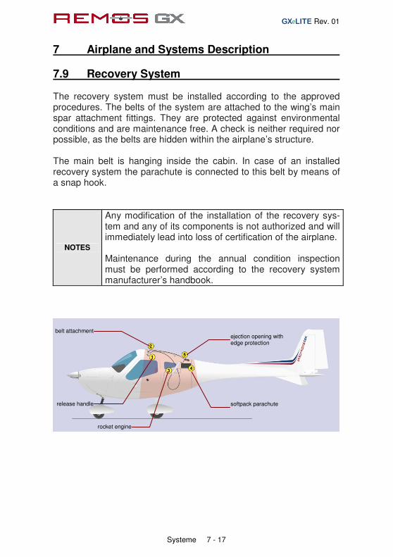
7.9 Recovery System The recovery system must be installed according to the approved procedures. The belts of the system are attached to the wing’s main spar attachment fittings. They are protected against environmental conditions and are maintenance free. A check is neither required nor possible, as the belts are hidden within the airplane’s structure. The main belt is hanging inside the cabin. In case of an installed recovery system the parachute is connected to this belt by means of a snap hook.
NOTES
Any modification of the installation of the recovery sys-tem and any of its components is not authorized and will immediately lead into loss of certification of the airplane. Maintenance during the annual condition inspection must be performed according to the recovery system manufacturer’s handbook.
release handle
belt attachment
rocket engine
softpack parachute
ejection opening with edge protection
general Rev. 04
8 Aircraft Ground Handling and Servicing
Aircraft Ground Handling and Servicing 8 - 1
Table of Content
sect. description page
8.1 Maintenance 8-2
8.2 Servicing Fuel, Oil and Coolant 8-2
8.3 Towing and Tie-Down Instructions 8-3
8.4 Rigging a Folded Aircraft 8-4
8.5 Folding a Rigged Aircraft 8-6
8.6 Transportation of the Aircraft 8-7
8.7 Cleaning and Care 8-7

general Rev. 04
8 Aircraft Ground Handling and Servicing
Aircraft Ground Handling and Servicing 8 - 2
8.1 Maintenance Maintenance procedures are defined in the maintenance manual that is specific to the individual aircraft. All maintenance shall be performed according to the REMOS Service and Maintenance Checklist, available directly at REMOS or on the website www.remos.com
8.2 Servicing Fuel, Oil and Coolant
Checking Oil and coolant
The REMOS GX is designed to be easily serviceable. Access to all components which have to be lubricated or checked regularly is possible without detaching any panels. A flap in the upper cowling allows checking coolant and oil without removing the cowling.
Fuelling the aircraft
The fuel filler cap is located on the right-hand side of the fuselage behind the wing. After removing the lockable fuel filler cap, refuelling is easily possible. Aircraft up to SN377 must be fuelled very carefully in order to prevent spilling of fuel. From SN378 on the fuel system has been modified to allow more rapid refuelling without spilling. The fuel tank vent line is also the overflow line and is located on the belly of the airplane. If the fuel tank is full (recognizable by the fuel nozzle shutting down), further filling of the tank will lead the fuel to overflow. The fuel tank is equipped with a sight tube to check fuel level. The sight tube can be found inside the cabin between the two seats. Do not overfill the fuel tank.

general Rev. 04
8 Aircraft Ground Handling and Servicing
Aircraft Ground Handling and Servicing 8 - 3
8.3 Towing and Tie-Down Instructions Due to the low weight of the REMOS GX, it is very easy to move the aircraft by hand on the ground. That’s why there is no special equipment for towing provided. Do not attempt under any circumstances to tow the aircraft by attaching any kind of towing equipment to the nose wheel! To tie down the aircraft we recommend the use of three ropes (left wing, right wing, and tail). Tie down each wing by attaching the rope to the lug located on the upper strut bracket. Another rope connection point is provided on the tail skid of the aircraft. When necessary, a fourth rope can be slid around the propeller/gear drive shaft at the nose of the aircraft. Aircrafts from SN380 are equipped with a thread on the lower side of the wing near the wingtips and are provided with bolt-in lugs. If required, bolt in the lugs and tie down the aircraft there. Do not fly with the tie-down lugs installed! Secure the control stick by use of the safety belt to prevent the control surfaces from being slammed from stop to stop by the wind.
NOTE The maximum wind velocity to leave a tied down aircraft in the open is 38 kts.

general Rev. 04
8 Aircraft Ground Handling and Servicing
Aircraft Ground Handling and Servicing 8 - 4
8.4 Rigging a Folded Aircraft The REMOS GX is manufactured to the highest quality standards. All components are very precise and provide the maximum aerodynamic quality. It is therefore strongly recommended that you be very careful when assembling or disassembling components such as the wings, stabilizer and other parts. The following instructions will provide you with all the necessary information.
NOTE
Folding or unfolding the wings and attaching or detaching the horizontal tail is a two person procedure. Do not to try this alone. Severe damage to the aircraft may result.
Tools, equipment and preparation
• bolt release tool (provided with the aircraft)
• screwdriver (Philips head)
• grease for bolts
• place the stabilizer behind the aircraft protective support
• remove both stabilizer bolts from their bushings
• remove both wing bolts from their bushings
general Rev. 04
8 Aircraft Ground Handling and Servicing
Aircraft Ground Handling and Servicing 8 - 5
Connecting folded wings to the fuselage
1. Unlock the fairings between the strut and the wing/fuselage and slide them along the strut.
2. Withdraw the main wing securing bolt from the wing and place it nearby. Ensure that the bolt stays clean until remounted.
3. Remove the wing support aid bracket while a second person supports the wing at the wing tip.
4. Now the second person at the wing tip moves the wing slowly forward while ensuring that the wing does not spin around its axis. The weight of the wing is supported by its strut, therefore, the wing must never be lifted or pushed down from the top.
5. When the wing has reached its maximum forward position, the person at the fuselage position must rotate the wing to align both connection latches. Care must be taken that the surface of the wing is not damaged by the fuselage connecting latches.
6. When the connecting latches between the fuselage and wing are aligned, the wing must be lifted by the person at the wing tip. The person at the fuselage must ensure that the flap drive connection fits correctly into the bushing on the fuselage.
7. If all latches have engaged and the wing fits properly to the fuselage, the main bolt can be pushed into its support tube. To install the main bolt correctly, please use the special installation tool which comes with the aircraft. Now secure the bolt with the securing pin. The person at the wing tip can now release the pressure supporting the wing tip.
8. Inside the cabin, the pushrod quick fasteners MUST properly be connected and secured.
Insecure connection, improper operation of control surfaces or insecurely locked fasteners will lead to loss of control of the aircraft!! When in doubt contact your local REMOS dealer or service center.
9. Proceed in the same order with the second wing.

general Rev. 04
8 Aircraft Ground Handling and Servicing
Aircraft Ground Handling and Servicing 8 - 6
Installing the horizontal tail
1. Hold the horizontal tail in place so that the bushings in the fuselage match up with those in the horizontal tail.
2. Apply the attachment bolts from left to right into their bushings. The forward bolt is marked by a "V", the rearward bolt by "H".
3. Align the hole of the attachment bolt with the one in the right bushing and secure the bolts with Fokker needles.
4. Connect the cable plug for the electric trim actuator
5. The pushrod quick fasteners MUST be connected properly and secured.
Insecure connection, improper operation of control surfaces or insecurely locked fasteners will lead to loss of control of the aircraft!! When in doubt contact your local REMOS dealer or service center.
6. Attach the tail cover and secure it with the screws provided. Connect the electric jack for the taillight.
After rigging the aircraft perform a preflight check.
8.5 Folding a Rigged Aircraft To disassemble the aircraft, perform the above described procedures in reverse order.

general Rev. 04
8 Aircraft Ground Handling and Servicing
Aircraft Ground Handling and Servicing 8 - 7
8.6 Transportation of the Aircraft If you intend to store the aircraft with the wings folded, we recommend using REMOS folding wing supports (ask your local dealer). With these supports mounted, the wings are secured properly and handling of the aircraft will be much easier. When the aircraft has to be moved by trailer, please ask your authorized REMOS dealer for advice. When placed on a trailer in a wrong way, serious damage could result.
8.7 Cleaning and Care After every day of flight, it is recommended that you clean the surface of the aircraft using pure water and a soft cotton towel only. Take special care when cleaning the windows to use lots of water to loosen and rinse away bugs and dirt and use with only a soft cotton towel, or otherwise you will create scratches. If cleaned regularly, you may not need to use any special cleaning products. If for any reason special cleaning products need to be used, please contact your dealer for advice. For polishing you can use almost any car polish but be sure that no silicone is used in that product.
Rev. 04 – November 2010
Imprint
Pilot Operating Handbook REMOS GX
ASTM Edition
Copyright REMOS Aircraft GmbH Flugzeugbau © REMOS 2007-2010, all rights reserved

Supplement Flight Training Revision general-04
general Rev. 04
Supplement Flight Training
Supplement Flight Training 9 - 1
Table of Content
sect. description page
1 Introduction 9-2
2 Take-Off 9-3
3 Climb 9-4
4 Cruise 9-5
5 Stall 9-6
6 Slip 9-7
7 Glide 9-8
8 Descent 9-9
9 Approach 9-10
10 Touch Down 9-12

general Rev. 04
1 Introduction
Supplement Flight Training 9 - 2
This chapter should enable you to familiarize yourself with the flight performance and flight characteristics of the REMOS GX. To complete these instructions, please refer to the appropriate sections in the POH.
The following pages describe flight characteristics experienced during various flight configurations and weather conditions:
• Take-off
• Climb
• Cruise
• Stall
• Slip
• Glide • Descent
• Approach
• Touch down
NOTE
This chapter was introduced as an additional guide to experience the capabilities of the aircraft, It is not a substitute for flight school training! If you are not yet familiar with the aircraft, we strongly recommend that you follow these instructions only when accompanied by a skilled flight instructor.

general Rev. 04
2 Take-Off
Supplement Flight Training 9 - 3
Take-off under normal conditions
1. After the pre-flight check has been completed, extend flaps to 15° for a grass runway. On a hard surface runway, take-off with clean flaps.
2. Ensure that the elevator trim is in the correct position. 3. Whenever possible, take-off directly into the wind. The
maximum demonstrated crosswind component for take-off is 15 kts.
4. Smoothly apply full throttle (fully forward) and maintain runway heading.
5. As the aircraft accelerates, gently pull back on the control stick to raise the nose slightly until the aircraft becomes airborne.
6. Once airborne, slowly release the back pressure on the control stick to allow the airspeed to increase to VX = 56 mph = 49 kts. Maintain this speed and avoid making any climbing turns until a sufficiently safe altitude has been reached.
7. When all obstacles have been cleared, retract the flaps (if they were deployed) and accelerate to VY = 75 mph = 65 kts.
Take-off under tailwind conditions
Similar to normal take-off except that the take-off distance will be extended. Ensure that you determine the take-off distance required to ensure you have sufficient runway length prior to take-off. Take-Off in rain or with a dirty aircraft
Surface conditions, high density altitude and temperatures, raindrops and bugs affect the performance of the aircraft. Be aware that in these conditions the performance figures will not meet the published figures, as they apply to a clean aircraft under standard atmospheric conditions. Expect a significant drop in performance.
general Rev. 04
3 Climb
Supplement Flight Training 9 - 4
Climb with Best Angle of Climb
With engine set to full power, establish VX, which is an indicated airspeed of 56 mph (49 kts). At this airspeed the aircraft will achieve the steepest angle of climb. During climb it is essential to monitor oil and water (CHT) temperatures. Adjust the oil temperature regulation flap as required. Climb with Best Rate of Climb
With engine set to full power, establish VY, which is an indicated airspeed of 75 mph (65 kts). At this airspeed the aircraft will achieve the best rate of climb. During climb it is essential to monitor oil and water (CHT) temperatures. Adjust the oil temperature regulation flap as required. Climb while in cruise
If you wish to climb in cruise, select an airspeed between 90 to 100 mph (78 to 86 kts). At these speeds, the aircraft will climb between 600 to 800 ft/min, depending on the weather conditions, altitude and weight of the aircraft. It is strongly recommended that you monitor oil and water (CHT) temperatures. Under no circumstances should any of the engine temperature limits be exceeded, otherwise, an engine failure may result. Climb in rain or with a dirty aircraft
Raindrops and bugs affect the performance of the aircraft. Be aware that in these conditions the performance figures will not meet the published figures, as they apply for a clean aircraft under standard atmospheric conditions. Expect a performance loss of 10% to15%.

general Rev. 04
4 Cruise
Supplement Flight Training 9 - 5
Normal cruise
An economical cruise is flown at engine speeds of 4,400 RPM to 4,800 RPM. With the Sensenich or Neuform propeller this will result in airspeeds between 98mph (85kts) and 111mph (97kts) with a fuel flow between 4 and 5 gph High speed cruise is done with engine speeds between 5,000 RPM and 5,400 RPM. With the Sensenich or Neuform propeller this will result in airspeeds between 117mph (102kts) and 130mph (113kts) with a fuel flow between 5 and 7 gph. If required, the aircraft is capable of achieving an airspeed up to 137 mph (119 kts) at full power settings. If doing so, always monitor the engine speed. The maximum continuous engine speed is 5,500 RPM and may only be sustained for 5 minutes. Do not exceed the maximum engine speed of 5,800 RPM. Cruise in gusty conditions
When flying in gusty weather conditions, the normal operating airspeed VNO = 123 mph (107 kts) should not be exceeded for safety reasons. The REMOS GX offers very stable flight characteristics even in heavy weather conditions. Cruise in rain or with dirty aircraft
Raindrops and bugs affect the performance of the aircraft. Be aware that in these conditions the performance figures will not meet the published figures, as they apply for a clean aircraft under standard atmospheric conditions. Expect a performance loss of 10% to15%. When flying in rain always activate the carburetor heat.
general Rev. 04
5 Stall
Supplement Flight Training 9 - 6
The REMOS GX is fully controllable when flying at a wide range of airspeeds. At airspeeds below the lower speed limit, the aircraft will display very stable stall characteristics. If the airspeed is reduced by the pilot gradually pulling back on the control stick, aerodynamic buffet will occur, indicating that the aircraft is approaching the stall speed. Should the aircraft then be allowed to stall, the aircraft still will remain controllable. The aircraft can be stalled with flaps both extended or retracted. Conducting a stall maneuver does not require special skills. However, if you are not yet familiar with the aircraft, we recommend you do this exercise only when accompanied by an experienced flight instructor.
general Rev. 04
6 Slip
Supplement Flight Training 9 - 7
The slip is a very stable flight condition and is also very easy to perform. This maneuver is used to increase aerodynamic drag to enable a high rate of descent. Before establishing a slip, you have to ensure that the airspeed is within the required limits. The maximum maneuvering speed VA = 108 mph (94 kts) should not be exceeded. If performing a slip with flaps extended, a maximum indicated airspeed of VFE= 81 mph (70 kts) must be maintained. You will achieve the maximum rate of descent when slipping with flaps fully extended and flying at VFE. Conducting a slip does not require special skills. However, if you are not yet familiar with the aircraft, we recommend to do this exercise only when accompanied by an experienced flight instructor.

general Rev. 04
7 Gliding
Supplement Flight Training 9 - 8
The aircraft can glide well with the engine off. Best glide ratios are achieved within an indicated airspeed of 75 mph (65 kts). These speeds will establish a glide ratio of about 1:10 with the flaps retracted (0° position).

general Rev. 04
8 Descent
Supplement Flight Training 9 - 9
When descending from level flight it is important to monitor engine temperatures. During descent, the temperatures will decrease, which could cause engine failure or carburetor icing to develop. therefore we strongly recommend that you not exceed the lower limits of these temperatures. Engage carburetor heat before beginning the descent.

general Rev. 04
9 Approach
Supplement Flight Training 9 - 10
Approach under normal conditions
Always land on the most suitable runway, taking into consideration wind direction, length of runway, obstacles on the approach, etc. The recommended airspeed for approach at MTOW is 75 mph (65 kts). Approach under tailwind conditions
When on final approach with a tailwind component, the REMOS GX does not require different approach or flare procedures than those used in calm or headwind conditions. However, you do have to keep in mind that the landing distance will increase significantly. Approach in crosswind conditions
Crosswinds do not have a big effect on the flight characteristics of the REMOS GX, as long as the cross-wind component stays within the maximum demonstrated speed of up to 15 kts. Performing a crosswind landing does not require above-average piloting skills. Nevertheless, if not yet familiar with the aircraft, we recommend that you perform crosswind landings only when accompanied by an experienced flight instructor until sufficient experience has been gained. Approach in turbulent weather conditions
The recommended airspeed for approach is 75 mph (65 kts) in turbulent conditions. This will give you a reserve airspeed to balance any unexpected deviations in altitude and heading. In more gusty conditions it may be beneficial to stabilize the glide slope by keeping the flap setting to the 15° position. Approach in rain showers
Raindrops on the wing surfaces influence the aerodynamic characteristics of the airfoil; drag will increase while lift decreases. The airfoil used on the REMOS GX features stable flight characteristics in rainy conditions. Therefore, there are no special advisories for flights within rain. we recommend that you operate the aircraft as you would in turbulent weather conditions (see "Approach in turbulent weather conditions). When flying in rain always activate the carburetor heat.

general Rev. 04
9 Approach
Supplement Flight Training 9 - 11
Approach in the slip configuration
If a high descent rate is required on final, we recommend that you conduct a slip maneuver. Conducting an approach in the slip configuration does not require special skills, however, if you are not yet familiar with the aircraft we recommend that yo do this exercise only when accompanied by an experienced flight instructor.

general Rev. 04
10 Touchdown
Supplement Flight Training 9 - 12
The aircraft has very good low speed characteristics and so is very controllable all the way through the landing phase. After a good approach has been conducted, the REMOS GX does not require much action to land with a perfect touch down. It is important to establish a safe and stable airspeed during the approach.

general Rev. 04
Imprint
Pilot Operating Handbook REMOS GX Supplement Flight Training
ASTM Edition
Copyright REMOS Aircraft GmbH Flugzeugbau © REMOS 2007-2010, all rights reserved

Supplement Glider Towing Revision 05

supplement glider towing Rev. 05
Supplement Glider Towing
Supplement Glider Towing 10 - 1
Table of Content
sect. description page
1 General Information 10-2
2 Operating Limitations 10-3
3 Emergency Procedures 10-5
4 Normal Procedures 10-7
5 Performance 10-10
6 Weight and Balance 10-16
7 Systems 10-17
8 Aircraft Ground Handling and Service 10-18

supplement glider towing Rev. 05
1 General Information
Supplement Glider Towing 10 - 2
1.1 Introduction This supplement is to be used only in addition to the REMOS GX Pilot Operating Handbook!
1.2 Certification The REMOS GX is manufactured in compliance with the rules of the Light Sport Aircraft airworthiness standards and does not conform to standard category airworthiness requirements.
1.3 Quick Reference For use as a glider towing aircraft, the REMOS GX is equipped with the TOST E85 tow release clutch, which is connected to the fuselage tail by a specially developed mounting frame. To release the tow rope a release lever is located on the left hand side of the pilot seat (colored yellow). Additionally, a rear view mirror must be installed inside the aircraft, above the pilot seat.

supplement glider towing Rev. 05
2 Operating Limitations
Supplement Glider Towing 10 - 3
2.1 Towing Speed max. towing speed VT of glider min. towing speed 1,3VS1 of glider, at least 56 mph (49 kts)
2.2 Tow Ropes length of tow rope 130 to 200 ft weak link max. 300 dN
2.3 Maximum Glider Take-Off Weight The maximum permissible take-off weight of the glider to be towed varies with the propeller mounted to the REMOS GX. The following operating limitations may not be exceeded: Propeller Glider
Tonini GT-2 1,210 lb [550kg]
Woodcom SR38+1 1,210 lb [550kg]
Sensenich R70EN 1,580 lb [720kg]
Neuform CR3-65 1,580 lb [720kg]
Rospeller 1,430 lb [650kg]
2.4 Crew During glider towing operations the REMOS GX must be operated only by one pilot (no passenger allowed, except for training/instruction). In all cases, the total take-off weight (towing aircraft + glider) must not exceed 2,900 lb.

supplement glider towing Rev. 05
2 Operating Limitations
Supplement Glider Towing 10 - 4
2.5 Minimum Equipment List
• as per D-VFR minimum equipment list, plus
• TOST tow release clutch type E85
• REMOS mounting frame for tow release clutch
• yellow colored release handle
• rear view mirror placed on main spar carrythrough
2.6 Flying Without Doors not permitted during towing operations
2.7 Required Placards and Markings Adjacent to the airspeed indicator: Adjacent to the tow release handle: At the release clutch bracket:
supplement glider towing Rev. 05
3 Emergency Procedures
Supplement Glider Towing 10 - 5
3.1 Engine Failure Procedure
Case 1: altitude not enough for engine re-start
1. AVIATE – NAVIGATE – COMMUNICATE
2. landing site IDENTIFY
3. glider pilot NOTIFIED
4. glider pilot RELEASE ROPE
5. engine OFF
6. fuel valve CLOSE
7. declare emergency MAYDAY MAYDAY MAYDAY
8. master switch OFF
9. safety belts TIGHTEN
10. tow rope RELEASE
11. emergency landing APPROPRIATE TERRAIN
Case 2: altitude sufficient for engine re-start
1. AVIATE – NAVIGATE – COMMUNICATE
2. landing site IDENTIFY
3. glider pilot NOTIFIED
4. glider pilot RELEASE ROPE
5. carburetor heat PULL
6. electric fuel pump ON
7. choke OFF
8. starter ENGAGE
9. if engine does not start continue with case 1
10. if engine starts, continue flight and land on an airfield
supplement glider towing Rev. 05
3 Emergency Procedures
Supplement Glider Towing 10 - 6
3.2 Abnormal Flight Attitude Procedure
1. AVIATE – NAVIGATE – COMMUNICATE
2. glider pilot NOTIFIED
3. engine REDUCE POWER
4. glider pilot RELEASE ROPE
5. recover gently and return to an airfield
NOTE
If the glider pilot cannot recover from the abnormal flight attitude and does not or cannot release the tow rope, the REMOS GX pilot must release the tow rope to recover from the abnormal flight attitude.
NOTE
If the abnormal flight attitude cannot be recovered from at all, the tow rope cannot be released, or the weak link does not break, activate the recovery system.
3.3 Failure of the Release Clutch Procedure
1. approach airspeed VAPP = 66 mph = 58 kts
2. full flaps airspeed VFE = 80 mph = 70 kts
3. flaps DOWN
4. variable pitch prop 5,600 rpm
5. engine power AS REQUIRED
6. elevator trim AS REQUIRED
7. electrical fuel pump ON
8. touchdown on main wheels first with elevator fully held back.
NOTE
The rope will hang down significantly from the aircraft due to its own weight. Therefore it can become tangled with obstacles, plants, wires, vehicles, persons, etc.

supplement glider towing Rev. 05
4 Normal Procedures
Supplement Glider Towing 10 - 7
4.1 Preflight Check Checklist
1. Perform standard preflight check
2. Check tow release clutch and test-release a tow rope
4.2 Take-Off Procedure
1. oil cooler flap OPEN
2. carburetor heat OFF
3. electric fuel pump ON
4. landing light RECOMMENDED
5. flaps 15 degrees
6. elevator trim 2/3 UP
7. rudder and aileron NEUTRAL
8. variable pitch prop 5,600 rpm
9. taxi forward ROPE STRAIGHT
10. engine power FULL POWER
11. rotate 62 mph = 54 kts
12. lift-off 75 mph = 65 kts
13. best climb VY = 75 mph = 65 kts
14. flaps RETRACT
NOTE
During take-off, special care must be taken that the climb rate and airspeed are compatible with the required values of the towed glider. Watch your rate of climb immediately after take-off (do not exceed the glider’s climb capability).
NOTE
To maintain permissible water and oil temperatures during climb and descent, the aircraft must be equipped with an oil temperature regulation flap. During climb the operating lever of this flap should be in the "open/cooler" position.

supplement glider towing Rev. 05
4 Normal Procedures
Supplement Glider Towing 10 - 8
4.3 Climb Briefing Flight tests have been conducted with various glider airplanes. These tests revealed that modern composite gliders, especially when loaded with water ballast, must be towed faster than older wooden sailplanes. The modern gliders are usually towed with airspeeds of 75 mph = 65 kts or possibly above that with flaps retracted. Older sailplanes can be towed with airspeeds as low as 48 mph = 56 kts; in that case select the 15 degrees flap setting.
4.4 Descent Checklist
1. flaps CLEAN
2. engine speed AS REQUIRED
3. electric fuel pump ON
4. maneuvering speed VA = 108 mph = 94 kts
5. normal operating speed VNO = 123 mph = 107 kts
6. never exceed speed VNE = 155 mph = 135 kts
7. max. cont. engine speed 5,500 rpm
8. carburetor heat RECOMMENDED
9. landing light RECOMMENDED
10. oil cooler flap AS REQUIRED
11. CHT max. 275°F = 135°C
12. oil temperature 120…266°F = 50…130°C
NOTE
Special care must be taken to keep all temperatures within the permissible range. To keep temperatures within the proper operation levels, the throttle may be left at a setting just above the idle position. Do not allow the oil temperature to drop rapidly.

supplement glider towing Rev. 05
4 Normal Procedures
Supplement Glider Towing 10 - 9
4.5 Approach Briefing
1. wind, weather, visibility OK
2. ATIS CHECKED
3. runway CORRECT DIRECTION
4. traffic circuit ALTITUDE and ROUTING
5. radios ON and FREQUENCY SET
6. transponder AS REQUIRED
7. full flaps BELOW 81 mph = 70kts
8. electric fuel pump ON
9. airspeed in pattern 95 to 125 mph = 80 to 110 kts
10. approach airspeed 75 mph = 65 kts
4.6 Landing Procedure
1. approach airspeed 75 mph = 65 kts
2. full flaps airspeed VFE = 80 mph = 70 kts
3. flaps DOWN
4. landing light RECOMMENDED
5. variable pitch prop 5,600 rpm
6. engine power AS REQUIRED
7. elevator trim AS REQUIRED
8. electric fuel pump ON
9. carburetor heat RECOMMENDED
10. oil cooler flap AS REQUIRED
11. CHT max. 275°F = 135°C
12. oil temperature 120 to 266°F = 50 to 130°C
13. tow rope RELEASE ON THRESHOLD
14. touchdown on main wheels first with elevator fully held back.
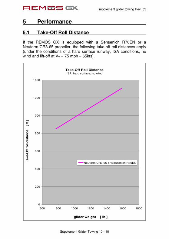
supplement glider towing Rev. 05
5 Performance
Supplement Glider Towing 10 - 10
5.1 Take-Off Roll Distance If the REMOS GX is equipped with a Sensenich R70EN or a Neuform CR3-65 propeller, the following take-off roll distances apply (under the conditions of a hard surface runway, ISA conditions, no wind and lift-off at VY = 75 mph = 65kts).
Take-Off Roll DistanceISA, hard surface, no wind
0
200
400
600
800
1000
1200
1400
600 800 1000 1200 1400 1600 1800
glider weight [ lb ]
Take-O
ff r
oll d
ista
nce [
ft ]
Neuform CR3-65 or Sensenich R70EN
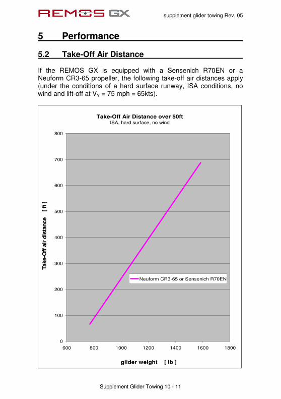
supplement glider towing Rev. 05
5 Performance
Supplement Glider Towing 10 - 11
5.2 Take-Off Air Distance If the REMOS GX is equipped with a Sensenich R70EN or a Neuform CR3-65 propeller, the following take-off air distances apply (under the conditions of a hard surface runway, ISA conditions, no wind and lift-off at VY = 75 mph = 65kts).
Take-Off Air Distance over 50ftISA, hard surface, no wind
0
100
200
300
400
500
600
700
800
600 800 1000 1200 1400 1600 1800
glider weight [ lb ]
Take-O
ff a
ir d
ista
nce [ ft
]
Neuform CR3-65 or Sensenich R70EN
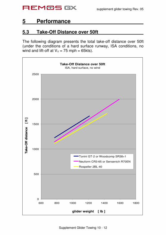
supplement glider towing Rev. 05
5 Performance
Supplement Glider Towing 10 - 12
5.3 Take-Off Distance over 50ft The following diagram presents the total take-off distance over 50ft (under the conditions of a hard surface runway, ISA conditions, no wind and lift-off at VY = 75 mph = 65kts).
Take-Off Distance over 50ftISA, hard surface, no wind
0
500
1000
1500
2000
2500
600 800 1000 1200 1400 1600 1800
glider weight [ lb ]
Take-O
ff d
ista
nce [
ft ]
Tonini GT-2 or Woodcomp SR38+1
Neuform CR3-65 or Sensenich R70EN
Rospeller 2BL-40

supplement glider towing Rev. 05
5 Performance
Supplement Glider Towing 10 - 13
5.4 Effects on Take-Off Distance Take-off distances given apply for ISA conditions and a dry, hard runway surface. Various circumstances have an effect on take-off and landing performance. According to ICAO-circular 601AN/55/2, it is recommended to use following add-ons for roll and air distances:
add-ons on take-off roll distance
for dry grass + 20%
for wet grass + 30%
for soft surface + 50%
per 2 knots tailwind component + 10%
per 10 knots headwind component - 10%
for high temperatures above standard + 10% per 10°C
for altitude above sea level (density altitude) + 5% per 1,000 ft
add-ons on take-off air distance
for dirty wings/raindrops + 15%
per 2 knots tailwind component + 10%
per 10 knots headwind component - 10%
for high temperatures above standard + 10% per 10°C
for altitude above sea level (density altitude) + 5% per 1,000 ft
All flight performance data are given for ISA standard atmosphere at sea level and standard temperature. To determine temperature in relation to ISA conditions please refer to the following chart.
NOTE
Especially in glider towing the take-off distances can vary significantly with precise flying habits and the drag of the glider.

supplement glider towing Rev. 05
5 Performance
Supplement Glider Towing 10 - 14
ISA std. Temperature
0
1000
2000
3000
4000
5000
6000
7000
8000
9000
10000
11000
12000
13000
14000
15000
-15 -10 -5 0 5 10 15
temperature [ °C ]
pre
ssu
re a
ltit
ud
e
[
ft ]

supplement glider towing Rev. 05
5 Performance
Supplement Glider Towing 10 - 15
5.5 Tested Glider Configuration The following gliders have been towed during flight tests: LS-1, LS-4, Baby-III, Astir and Twin Astir, Hornbach, Junior, Jantar, Pirat, Puchacz, Discus and DuoDiscus, Blanik, DG-100/300/500, DG-1000, ASK-21 and ASW-24, Nimbus and Cirrus, Cobra, PIK-20.
5.6 Remarks Based on the rules of the Light Sport Aircraft airworthiness standards, the maximum dimension is defined by the weight of the glider to be towed, without consideration of glider aerodynamics. During the flight test with the DG-1000T, a maximum permissible glider weight of 1,580 lb has been demonstrated. For gliders with a maximum permissible glider weight of 1,580lb, but less favourable aerodynamics than the DG-1000T, a lower climb rate and significantly longer take-off distance are to be expected.
NOTE
Inexperienced pilots should start with a one person lightweight glider and increase the glider weight step by step.
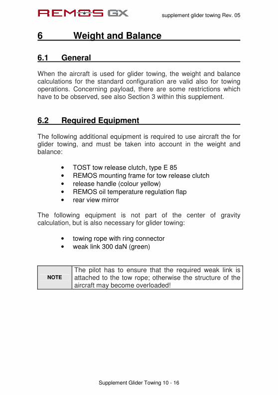
supplement glider towing Rev. 05
6 Weight and Balance
Supplement Glider Towing 10 - 16
6.1 General When the aircraft is used for glider towing, the weight and balance calculations for the standard configuration are valid also for towing operations. Concerning payload, there are some restrictions which have to be observed, see also Section 3 within this supplement.
6.2 Required Equipment The following additional equipment is required to use aircraft the for glider towing, and must be taken into account in the weight and balance:
• TOST tow release clutch, type E 85
• REMOS mounting frame for tow release clutch
• release handle (colour yellow)
• REMOS oil temperature regulation flap
• rear view mirror The following equipment is not part of the center of gravity calculation, but is also necessary for glider towing:
• towing rope with ring connector
• weak link 300 daN (green)
NOTE
The pilot has to ensure that the required weak link is attached to the tow rope; otherwise the structure of the aircraft may become overloaded!

supplement glider towing Rev. 05
7 Systems
Supplement Glider Towing 10 - 17
The tow release handle is installed inside the cabin of the REMOS GX. The handle is located on the left hand side of the pilot seat, colored yellow. Pulling the handle releases the tow rope. The handle should provide a free play of 1/2 to 1 Inch.

supplement glider towing Rev. 05
8 Aircraft Ground Handling and Service
Supplement Glider Towing 10 - 18
During regular servicing intervals, the tow release clutch must be cleaned, lubricated and checked to assure proper operation. A general overhaul of the release clutch must be conducted every 4 years or 4,000 towing operations, whatever comes first. For further information refer to the separate operator’s manual of the manufacturer.
supplement glider towing Rev. 05
Imprint
Pilot Operating Handbook REMOS GX Supplement Glider Towing
ASTM Edition
Copyright REMOS Aircraft GmbH Flugzeugbau © REMOS 2007-2011, all rights reserved