pilot specification for ol rank-1 region document number: ieee c80216m-09_1915 date submitted:...
TRANSCRIPT

Pilot specification for OL rank-1 region
Document Number: IEEE C80216m-09_1915
Date Submitted: 2009-08-29
Source:Kiran Kuchi, J. Klutto Milleth, Padmanabhan M S Voice:CEWiT, India E-mail:
[email protected], [email protected]
Venue: Comments on P802.16m/D1
Base Contribution: None
Purpose: To discuss and adopt the proposed text in section 15.3.5.4.1
To discuss in TGm for appropriate action. Notice:This document does not represent the agreed views of the IEEE 802.16 Working Group or any of its subgroups. It represents only the views of the participants listed in the “Source(s)” field
above. It is offered as a basis for discussion. It is not binding on the contributor(s), who reserve(s) the right to add, amend or withdraw material contained herein.
Release:The contributor grants a free, irrevocable license to the IEEE to incorporate material contained in this contribution, and any modifications thereof, in the creation of an IEEE Standards
publication; to copyright in the IEEE’s name any IEEE Standards publication even though it may include portions of this contribution; and at the IEEE’s sole discretion to permit others to reproduce in whole or in part the resulting IEEE Standards publication. The contributor also acknowledges and accepts that this contribution may be made public by IEEE 802.16.
Patent Policy:The contributor is familiar with the IEEE-SA Patent Policy and Procedures:
<http://standards.ieee.org/guides/bylaws/sect6-7.html#6> and <http://standards.ieee.org/guides/opman/sect6.html#6.3>.Further information is located at <http://standards.ieee.org/board/pat/pat-material.html> and <http://standards.ieee.org/board/pat >.

Background
For a reuse 1 system, the strongest
interference for a cell edge user comes
from those sectors with sector numbers
different from its desired one
The SINR seen by the pilot symbols can
be significantly improved by avoiding
pilot to pilot collisions between sectors
Improves Channel Estimation
Improves Covariance Estimation

Interlaced Pilots
Interlaced pilots use pilot patterns which are cyclically shifted, resulting in
the collisions between pilot and data.
But, the use of interlaced pilots (with power boosting) has the following
disadvantages :
It reduces the data SINR.
Interference suppression receivers can not function smoothly, because of the mismatch between
the estimated covariance and the actual covariance in the data locations that do not have power
boosting
With CDR encoding, conjugate data pairs collide with pilots. Therefore, the number of samples
available for interference covariance estimation is half – compared to pilot-on-pilot case.
In general, poor CDR performance with interlaced pilots
Pilot on Pilot
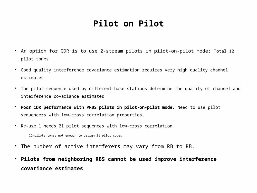
An option for CDR is to use 2-stream pilots in pilot-on-pilot mode: Total 12 pilot tones
Good quality interference covariance estimation requires very high quality channel estimates
The pilot sequence used by different base stations determine the quality of channel and
interference covariance estimates
Poor CDR performance with PRBS pilots in pilot-on-pilot mode. Need to use pilot sequencers
with low-cross correlation properties.
Re-use 1 needs 21 pilot sequences with low-cross correlation
12-pilots tones not enough to design 21 pilot codes
The number of active interferers may vary from RB to RB.
Pilots from neighboring RBS cannot be used improve interference
covariance estimates
Collision Free Interlaced Pilots(CoFIP)
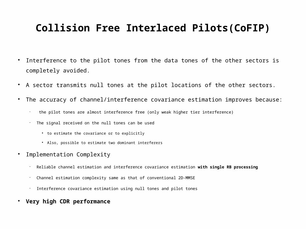
Interference to the pilot tones from the data tones of the other sectors is completely avoided.
A sector transmits null tones at the pilot locations of the other sectors.
The accuracy of channel/interference covariance estimation improves because:
the pilot tones are almost interference free (only weak higher tier interference)
The signal received on the null tones can be used
to estimate the covariance or to explicitly
Also, possible to estimate two dominant interferers
Implementation Complexity
Reliable channel estimation and interference covariance estimation with single RB processing
Channel estimation complexity same as that of conventional 2D-MMSE
Interference covariance estimation using null tones and pilot tones
Very high CDR performance
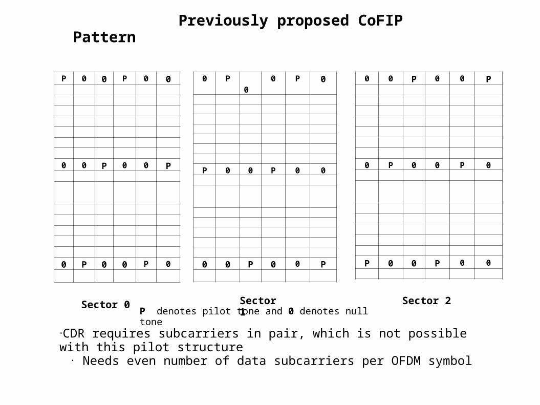
Sector 0
0 P 0 0 P 0
P 0 0 P 0 0
0 0 P 0 0 P
P denotes pilot tone and 0 denotes null tone
P 0 0 P 0 0
0 0 P 0 0 P
0 P 0 0 P 0
Previously proposed CoFIP Pattern
0 0 P 0 0 P
0 P 0 0 P 0
P 0 0 P 0 0
Sector 1
Sector 2
•CDR requires subcarriers in pair, which is not possible with this pilot structure• Needs even number of data subcarriers per OFDM symbol
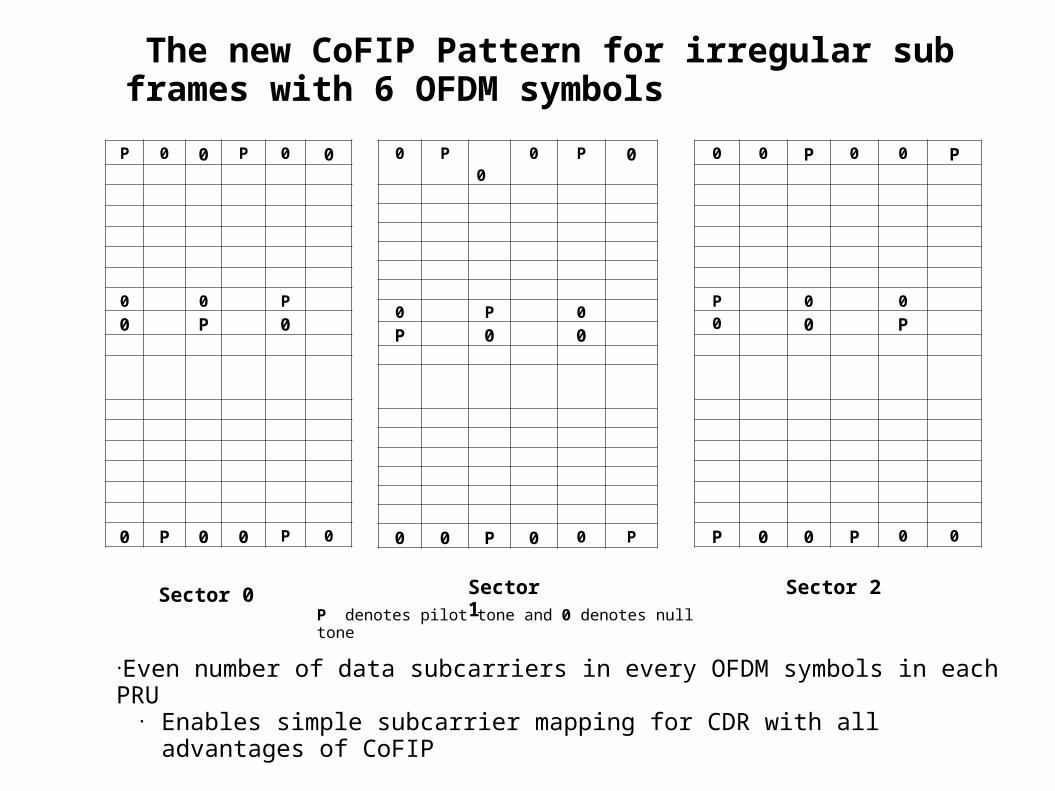
Sector 0
0 P 0 0 P 0
0 P 0P 0 0
0 0 P 0 0 P
P denotes pilot tone and 0 denotes null tone
P 0 0 P 0 0
0 0 P0 P 0
0 P 0 0 P 0
The new CoFIP Pattern for irregular sub frames with 6 OFDM symbols
0 0 P 0 0 P
P 0 00 0 P
P 0 0 P 0 0
Sector 1
Sector 2
•Even number of data subcarriers in every OFDM symbols in each PRU• Enables simple subcarrier mapping for CDR with all advantages of CoFIP

Sector 0
0 P 0 0 P
0 P 0 0P 0 P 0
0 0 P 0 0
P denotes pilot tone and 0 denotes null tone
P 0 0 P 0
0 0 0 P0 P 0 0
0 P 0 0 P
The new CoFIP Pattern for irregular sub frames with 5 OFDM symbols
0 0 P 0 0
P 0 P 0
0 0 0 P
P 0 0 P 0
Sector 1
Sector 2
•For 18 X 7 RBs, add the first OFDM OFDM symbol after 6th OFDM

Estimation of interference covariance
The interference covariance matrix is estimated using all
the symbols received at the pilot/null locations
The covariance is estimated from the pilot tones
corresponding to the same sector number, and from the
null tones of different sector numbers
The CQI estimates are very stable
Channel estimation and interference covariance estimation
confined to 1 RB processing

Pilot sequences for CoFIP
The pilot sequences assigned to different cells should
have low cross correlation within the space of an RB.
Some of the possibilities are:
Use of short pilot sequences, which have low cross-correlation within a
localized resource unit.
Use of long PN sequences
Results in increased cross correlation

Short PN sequence
Seven PN sequences are generated using an LFSR with the characteristic polynomial X3+X +1
The first 6 samples of a sequence is used for deriving the 6 pilots with in a PRU
Two pilot allocation methods are suggested:
Method 1: The same sequence is used in different PRUs of a cell
Method 2: The sequence used in different PRUs of a cell are different
Definitions:
A cell is a collection of 3 sectors and is assigned unique id = CellID
PRU index ‘s’ in frequency and sub-frame number ‘t’ in time
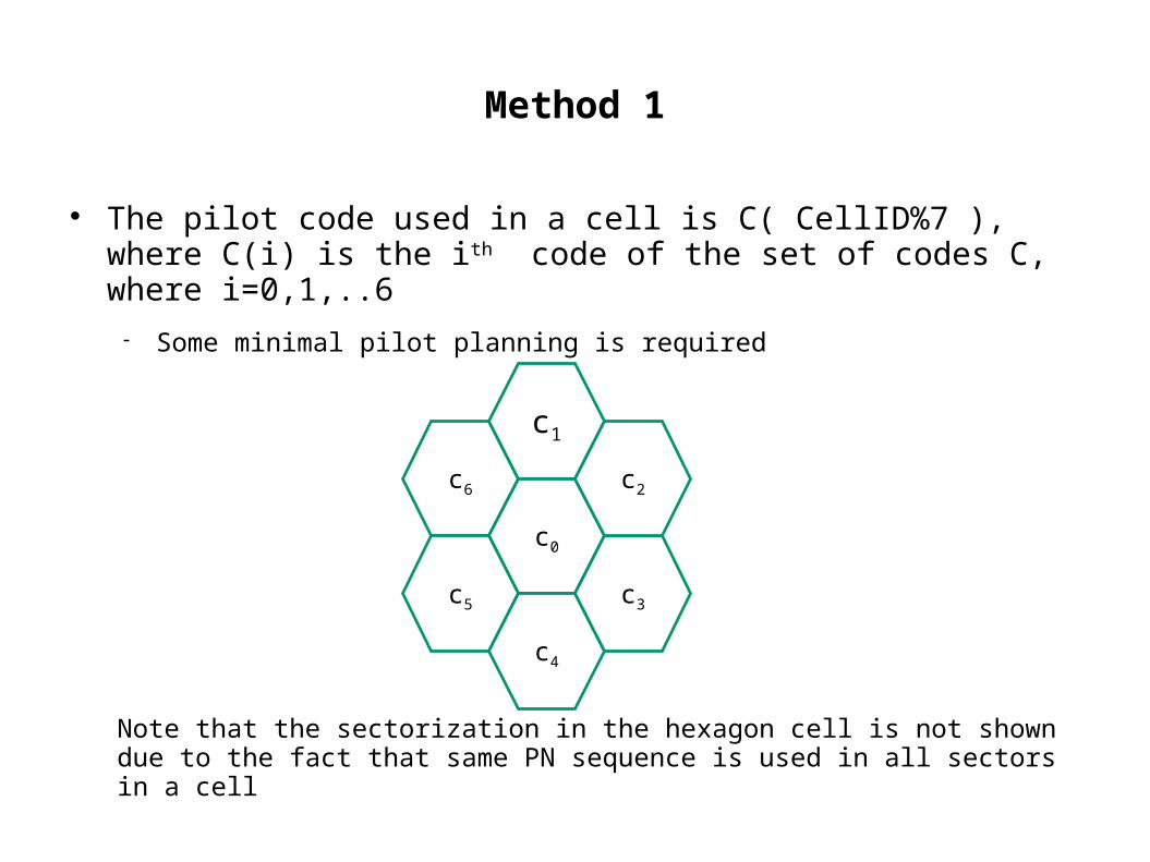
Method 1
The pilot code used in a cell is C( CellID%7 ), where C(i) is the i th code of the set of codes C, where i=0,1,..6
Some minimal pilot planning is required
c6
c1
c0
c5
c4
c3
c2
Note that the sectorization in the hexagon cell is not shown due to the fact that same PN sequence is used in all sectors in a cell

Method 2
Pilot sequence cycling in time and/or frequency is implemented to
exploit the advantage of interference averaging on the pilots. The
pilot code used in a cell with CellID = k is C( (s+t+k)%7), where C(i) is
the ith code of the set of codes C. i=0,1,…6
cell_ID = 0 cell_ID=1 cell_ID=2
C0 C1 C2 C3 C4
C1 C2 C3 C4 C5
C2 C3 C4 C5 C6
C3 C4 C5 C6 C0
C1 C2 C3 C4 C5
C2 C3 C4 C5 C6
C3 C4 C5 C6 C0
C4 C5 C6 C0 C1
C2 C3 C4 C5 C6
C3 C4 C5 C6 C0
C4 C5 C6 C0 C1
C5 C6 C0 C1 C2
s
t -->

Long PN sequence
Long PN sequences are generated using an LFSR with the
characteristic polynomial X11+X9 +1
The LFSR is initialized as follows:
b0...b6 = (CellID % 128 ) + 1
b7...b10 = (symbol index % 16)
For the ith OFDM symbol, a PN sequence PNi(k) , k=0,1,2,....
(FFTSI-1) is generated
The pilot tone (i,k) ( ith OFDM symbol, kth sub-carrier ) is modulated
with PNi(k)
Pilot planning is not necessary

Comparison of Various Pilot Modes
Pilot-on-Data Pilot-on-Pilot COFiP
Total overhead 5.5% 11.1% 16.6%
Channel estimation complexity
Low Medium Low
Performance Very Poor Poor High
1) Pilot-on-Data is not suitable for CDR2) COFiP needs 5.5% more overhead compared to COFiP 3) In spite of additional overhead, COFiP outperforms pilot-on-pilot significantly

Conjugate Data Repetition (CDR) with CoFIP
Simulation parameters
2Tx antenna – 2Rx antenna
Channel: Modified Ped B, 7 Hz doppler
3 interferers of equal power. One interferer colliding with pilot tones and the remaining two
interferers on null tones (Some what worst case scenario. In practice, the CCI on pilots is much
weaker)
Thermal noise level is 10 dB below the power of one of the interferers.
Twenty 18x6 RBs, 4 in freq. and 5 in time. All estimation is done within a single RB
2D-MMSE did not exploit knowledge of pilot sequence used by the CCI which collides with pilot
tones
The new CoFIP pilot pattern is used.
Performance with Short and long PN pilot sequences are compared.

CDR performance with different short PRBS

CDR Performance comparison between short and log PRBS

Conclusions
COFiP Low implementation complexity Additional overhead gives robustness in design,
reduces implementation complexity, higher overall system performance
Recommends COFiP with short PRBS 7- pilot codes with low-cross correlation with minimal pilot
planning
Pilot-on-Pilot with long PRBS significantly worse than COFiP

Proposed Text OL rank-1 uses collision free interlaced pilots. The index of the COFiP PRU type
used by a particular BS with Cell_ID=k is denoted by pk. The index of the used CoFIP type PRU is determined by the Cell_ID according to the following equation: pk
= mod(k,3)
In the Fig xxxx ‘X’ donates a null tone i.e., no data or pilot tone is transmitted in that location
COFiP Type 0 PRU
COFiP Type 1 PRU
COFiP Type 2 PRU
0 P 0 0 P 0
0 P 0P 0 0
0 0 P 0 0 P
P 0 0 P 0 0
0 0 P0 P 0
0 P 0 0 P 0
0 0 P 0 0 P
P 0 00 0 P
P 0 0 P 0 0

Proposed Text
Pilot Sequence Definition: Define 7- codes: C(j), j=0..6. [TBD] The pilot code used in a cell with Cell_ID = k is
P=C( (s+t+k)%7), where C(i) is the ith code of the set of codes C(i). i=0,1,…6
P=[p(0) p(1) … p(5)] where p(i), i=0,..,5 is the ith pilot symbol in Fig xxx