pilot’s guide ki 825 bendix/king safety display system
TRANSCRIPT

Pilot’s Guide
Bendix/King®
Safety Display SystemElectronic Horizontal Situation Indicator
KI 825KI 825
N
Pilot’s Guide
Bendix/King®
Safety Display SystemElectronic Horizontal Situation Indicator
For Units Having “-2”, “-3” and “-4” Softwa re

W A R N I N G
The enclosed technical data is eligible for export under Licanse Designation NLRand is to be used solely by the individual/organization to whom it is addressed.Diversion contrary to U.S. law is prohibited.
COPYRIGHT NOTICE
Copyright ©2002, 2004, 2008 Honeywell International Inc. All rightsr e s e r v e d .
Reproduction of this publication or any portion thereof by any means without theexpress written permission of Honeywell International Inc. is prohibited. For fur-ther information contact the Manager, Technical Publications; Honeywell; OneTechnology Center; 23500 West 105th Street; Olathe, Kansas 66061.Telephone: (913) 712-0400.
KI 825 PG R2 Cover.qxd 4/16/08 5:08 PM Page 2

R-1
Revision History and Instructions
Manual KI 825 Pilot’s Guide
Revision 3, Apr 2008
Part Number 006-18280-0000
This revision incorporates Software Level -4.
The following pages were changed:
Front Cover, Copyright, SW Level Pages 1, TOC2, i, 1-2, 1-3, 1-4, 1-7,1-10, 1-18, 2-3, 2-7, 2-8, 2-10, 2-12, 2-13, 2-14 3-2, 3-4, A-2. BackCover

Revision History and Instructions
Manual KI 825 Pilot’s Guide
Revision 2, May 2004
Part Number 006-18280-0000
This revision incorporates Software Level -3.
The following pages were changed:
Front Cover, Copyright, SW Level Pages, TOC 1, TOC 2, 1-4~1-7, 1-10,1-18, 2-3, 2-4, 2-7~2-16, Back Cover
R-2
R-3
Revision History and Instructions
Manual KI 825 Pilot’s Guide
Revision 1, December 2002
Part Number 006-18280-0000
The following pages have been updated.
Page i Updated page number for 1.1.11.
Page 1-2 Changed callout from Course Arrow to Course Pointer in Figure 1-1.
Page 1-8 Removed the word yellow from 1.1.15.
Page 1-12 Changed callout from Course Deviation Indicator to Course Deviation Pointer in Figure 1-6.
Page 3-2 Changed callout from Glideslope Flag (pointer removed)to Course Deviation Flag (pointer removed). Also removed Glideslope Scale callout and arrow from Figure 3-2.

R-4
Revision History and Instructions
Manual KI 825 Pilot’s Guide
Revision 0, December 2002
Part Number 006-18280-0000
This is the original version of this publication..

KI 825 Pilot’s Guide
006-18280-0000 (April 2008)
For Units Having Software Version 80-5205-X-4
The software version number is displayed in the upper left corner of theKI 825 display for several seconds when it is first turned on after a “coldstart”. In the figure below the software version is 80-5205-X-3. For this ver-sion it will read 80-5205-X-4.
Note: The KI 825 performs a cold start only when power has been off forfive minutes or longer. If the software version number is not displayedwhen power is applied to the unit, turn power off for at least five minutesbefore reapplying power.
In this Pilot’s Guide the operational description is applicable to all softwareversions unless “Software Version -2 Only” , “Software Version -3 Only”or “Software Version -4 Only ”is specifically indicated in the text.
Operational characteristics of software version 80-5205-X-4, is similar to80-5205-X-3 but have the following enhancements:
1 . VNAV or vertical deviation is provided when the selected navigationalsource is a GPS and it is in approach phase.
1
2
I
Operational characteristics of software version 80-5205-X-3 are similar to80-5205-X-2 but have the following enhancements:
1 . Allows for the option of separate day and night display dimmingranges controlled by an external day/night switch. See section 2.5.
2 . Requires the user to press the MENU button in order to change thedisplayed navigation sensor and to utilize the memory load function.See sections 2.2, 2.3, 2.7, and 2.13.
3 . Allows for the option of an external switch to be utilized in changingbetween GPS and VOR in addition to the existing method of naviga-tion sensor selection from the KI 825 menu. See section 2.14.
4 . Removes the “CLR” option prompt on the right side of the MENUwhen clearing lightning strikes from the 360 Map and Arc Map dis-plays. Note, there is no operational change to this feature. Thischange was made to improve consistency in the use of optionsp r o m p t s . See section 2.4.
5 . Provides for more optimized installation interfaces with units like theGarmin GNS 430/530 such that GPS/VLOC switching can now beaccomplished from both the GNS 430/530 and from the KI 825. Thisincludes the capability of having the GNS 430/530 change the KI 825displayed navigation sensor during an automatic GPS to ILS transi-tion. See sections 2.15 and 2.16.
6 . Allows for an installation option to not utilize the KI 825’s standardcourse storage feature. This provides more efficient operation whenutilizing the automatic GPS to ILS switching capability offered by unitssuch as the Garmin GNS 430/530. See section 1.1.4.

3
5. Provides for more optimized installation interfaces with units like theGarmin GNS 430/530 such that GPS/VLOC switching can now beaccomplished from both the GNS 430/530 and from the KI 825. Thisincludes the capability of having the GNS 430/530 change the KI 825displayed navigation sensor during an automatic GPS to ILS transi-tion. See sections 2.15 and 2.16.
6. Allows for an installation option to not utilize the KI 825’s standardcourse storage feature. This provides more efficient operation whenutilizing the automatic GPS to ILS switching capability offered by unitssuch as the Garmin GNS 430/530. See section 1.1.4.
KI 825 Pilot’s Guide Table of Contents
TOC-1
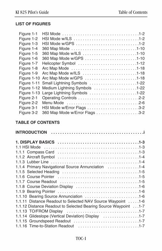
LIST OF FIGURES
Figure 1-1 HSI Mode . . . . . . . . . . . . . . . . . . . . . . . . . . . . . . . . . .1-2Figure 1-2 HSI Mode w/ILS . . . . . . . . . . . . . . . . . . . . . . . . . . . . .1-2Figure 1-3 HSI Mode w/GPS . . . . . . . . . . . . . . . . . . . . . . . . . . . .1-2Figure 1-4 360 Map Mode . . . . . . . . . . . . . . . . . . . . . . . . . . . . .1-10Figure 1-5 360 Map Mode w/ILS . . . . . . . . . . . . . . . . . . . . . . . .1-10Figure 1-6 360 Map Mode w/GPS . . . . . . . . . . . . . . . . . . . . . . .1-10Figure 1-7 Helicopter Symbol . . . . . . . . . . . . . . . . . . . . . . . . . .1-12Figure 1-8 Arc Map Mode . . . . . . . . . . . . . . . . . . . . . . . . . . . . .1-18Figure 1-9 Arc Map Mode w/ILS . . . . . . . . . . . . . . . . . . . . . . . .1-18Figure 1-10 Arc Map Mode w/GPS . . . . . . . . . . . . . . . . . . . . . . .1-18Figure 1-11 Small Lightning Symbols . . . . . . . . . . . . . . . . . . . . .1-22Figure 1-12 Medium Lightning Symbols . . . . . . . . . . . . . . . . . . .1-22Figure 1-13 Large Lightning Symbols . . . . . . . . . . . . . . . . . . . . .1-22Figure 2-1 Operating Controls . . . . . . . . . . . . . . . . . . . . . . . . . . .2-2Figure 2-2 Menu Mode . . . . . . . . . . . . . . . . . . . . . . . . . . . . . . . .2-6Figure 3-1 HSI Mode w/Error Flags . . . . . . . . . . . . . . . . . . . . . . .3-2Figure 3-2 360 Map Mode w/Error Flags . . . . . . . . . . . . . . . . . . .3-2
TABLE OF CONTENTS
INTRODUCTION . . . . . . . . . . . . . . . . . . . . . . . . . . . . . . . . . . . . . . . . .i
1. DISPLAY BASICS . . . . . . . . . . . . . . . . . . . . . . . . . . . . . . . . . . . .1-3
1.1 HSI Mode . . . . . . . . . . . . . . . . . . . . . . . . . . . . . . . . . . . . . . . . . .1-31.1.1 Compass Card . . . . . . . . . . . . . . . . . . . . . . . . . . . . . . . . . . . .1-31.1.2 Aircraft Symbol . . . . . . . . . . . . . . . . . . . . . . . . . . . . . . . . . . . .1-41.1.3 Lubber Line . . . . . . . . . . . . . . . . . . . . . . . . . . . . . . . . . . . . . . .1-41.1.4 Primary Navigational Source Annunciation . . . . . . . . . . . . . .1-41.1.5 Selected Heading . . . . . . . . . . . . . . . . . . . . . . . . . . . . . . . . . .1-51.1.6 Course Pointer . . . . . . . . . . . . . . . . . . . . . . . . . . . . . . . . . . . .1-51.1.7 Course Readout . . . . . . . . . . . . . . . . . . . . . . . . . . . . . . . . . . .1-51.1.8 Course Deviation Display . . . . . . . . . . . . . . . . . . . . . . . . . . . .1-61.1.9 Bearing Pointer . . . . . . . . . . . . . . . . . . . . . . . . . . . . . . . . . . . .1-61.1.10 Bearing Source Annunciation . . . . . . . . . . . . . . . . . . . . . . . .1-61.1.11 Distance Readout to Selected NAV Source Waypoint . . . . .1-61.1.12 Distance Readout to Selected Bearing Source Waypoint . . .1-71.1.13 TO/FROM Display . . . . . . . . . . . . . . . . . . . . . . . . . . . . . . . .1-71.1.14 Glideslope (Vertical Deviation) Display . . . . . . . . . . . . . . . .1-71.1.15 Groundspeed Readout . . . . . . . . . . . . . . . . . . . . . . . . . . . . .1-71.1.16 Time-to-Station Readout . . . . . . . . . . . . . . . . . . . . . . . . . . .1-7
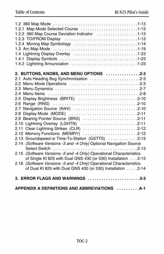
Table of Contents KI 825 Pilot’s Guide
TOC-2
1.2 360 Map Mode . . . . . . . . . . . . . . . . . . . . . . . . . . . . . . . . . . . . .1-131.2.1 Map Mode Selected Course . . . . . . . . . . . . . . . . . . . . . . . . .1-131.2.2 360 Map Course Deviation Indicator . . . . . . . . . . . . . . . . . .1-131.2.3 TO/FROM Display . . . . . . . . . . . . . . . . . . . . . . . . . . . . . . . .1-131.2.4 Moving Map Symbology . . . . . . . . . . . . . . . . . . . . . . . . . . . .1-141.3 Arc Map Mode . . . . . . . . . . . . . . . . . . . . . . . . . . . . . . . . . . . . .1-191.4 Lightning Display Overlay . . . . . . . . . . . . . . . . . . . . . . . . . . . .1-231.4.1 Display Symbols . . . . . . . . . . . . . . . . . . . . . . . . . . . . . . . . . .1-231.4.2 Lightning Annunciation . . . . . . . . . . . . . . . . . . . . . . . . . . . . .1-23
2. BUTTONS, KNOBS, AND MENU OPTIONS . . . . . . . . . . . . . . .2-32.1 Auto Heading Bug Synchronization . . . . . . . . . . . . . . . . . . . . . .2-32.2 Menu Mode Operations . . . . . . . . . . . . . . . . . . . . . . . . . . . . . . .2-32.3 Menu Dynamics . . . . . . . . . . . . . . . . . . . . . . . . . . . . . . . . . . . . .2-72.4 Menu Items . . . . . . . . . . . . . . . . . . . . . . . . . . . . . . . . . . . . . . . .2-82.5 Display Brightness (BRITE) . . . . . . . . . . . . . . . . . . . . . . . . . .2-102.6 Range (RNG) . . . . . . . . . . . . . . . . . . . . . . . . . . . . . . . . . . . . .2-102.7 Navigation Source (NAV) . . . . . . . . . . . . . . . . . . . . . . . . . . . .2-102.8 Display Mode (MODE) . . . . . . . . . . . . . . . . . . . . . . . . . . . . . .2-112.9 Bearing Pointer Source (BRG) . . . . . . . . . . . . . . . . . . . . . . . .2-112.10 Lightning Overlay (LGHTN) . . . . . . . . . . . . . . . . . . . . . . . . .2-112.11 Clear Lightning Strikes (CLR) . . . . . . . . . . . . . . . . . . . . . . . .2-122.12 Memory Functions (MEMRY) . . . . . . . . . . . . . . . . . . . . . . . .2-122.13 Groundspeed or Time-To-Station (GSTTS) . . . . . . . . . . . . .2-132.14 (Software Versions -3 and -4 Only) Optional Navigation Source
Select Switch . . . . . . . . . . . . . . . . . . . . . . . . . . . . . . . . . . . . .2-132.15 (Software Versions -3 and -4 Only) Operational Characteristics
of Single KI 825 with Dual GNS 430 (or 530) Installation . . . .2-132.16 (Software Versions -3 and -4 Only) Operational Characteristics
of Dual KI 825 with Dual GNS 430 (or 530) Installation . . . . .2-14
3. ERROR FLAGS AND WARNINGS . . . . . . . . . . . . . . . . . . . . . . .3-3
APPENDIX A DEFINITIONS AND ABBREVIATIONS . . . . . . . . . .A-1
KI 825 Pilot’s Guide Introduction
i
INTRODUCTION
The KI 825 combines critical flight information in an easy-to-use, high-res-olution presentation. At the touch of a button, a pilot can configure thepresentation to display only what’s required for the phase of flight. It con-tains all of the hardware and software functions necessary to displayinformation to the pilot concerning the operation of a Horizontal SituationIndicator (HSI) or Navigation Map Display.
The KI 825 combines the display functions of the standard DirectionalGyro with VOR/LOC course deviation indication, glideslope/vertical devia-tion (Vertical VNAV deviation is only available with Software version 4),and bearing.
When interfaced to a GPS system, the KI 825 will display a GPS flightpath with waypoint indications. When interfaced to a lightning detectionsystem, it will provide the pilot information concerning storm activity.
Due to different aircraft system configurations, such as number of or typeof interfaces for the NAV or GPS systems or presence of lightning sys-tems, some features or capabilities of the EHSI may not be available for aparticular aircraft installation.
This Pilot’s Guide will introduce you to the KI 825 and walk you throughthe step-by-step operation of its many features. This guide assumes youhave basic operating knowledge of a Horizontal Situation Indicator andexplains how you can make full use of the KI 825 Safety Display Systemin place of an electromechanical HSI.
More importantly, the KI 825 is a flight instrument intended to help mini-mize pilot workload, reduce cross cockpit scanning, and increasesituational awareness. Even with the KI 825’s substantial capabilities,don’t forget to exercise good basic piloting techniques in responsibly andsafely flying your aircraft.

Introduction KI 825 Pilot’s Guide
ii
This page left blank intentionally

KI 825 Pilot’s Guide Chapter 1 Display Basics
1-1
This page left blank intentionally.
Chapter 1 Display Basics
1-2
TRIM
1. DISPLAY BASICS
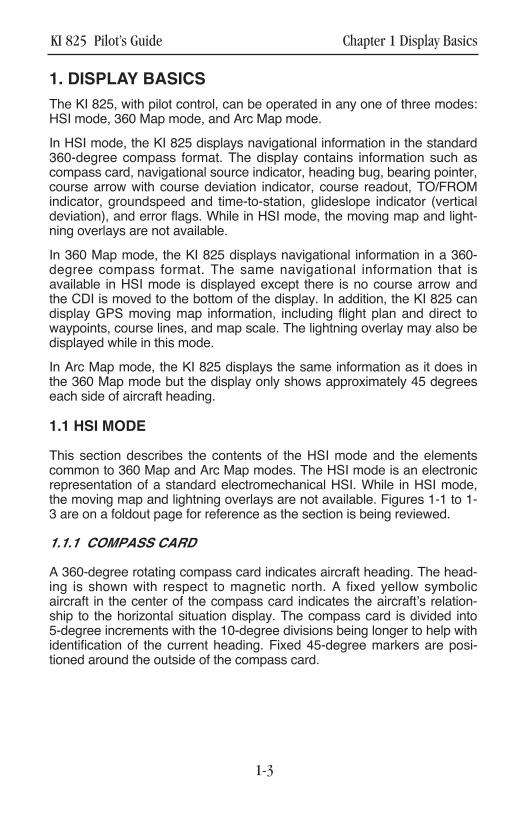
The KI 825, with pilot control, can be operated in any one of three modes:HSI mode, 360 Map mode, and Arc Map mode.
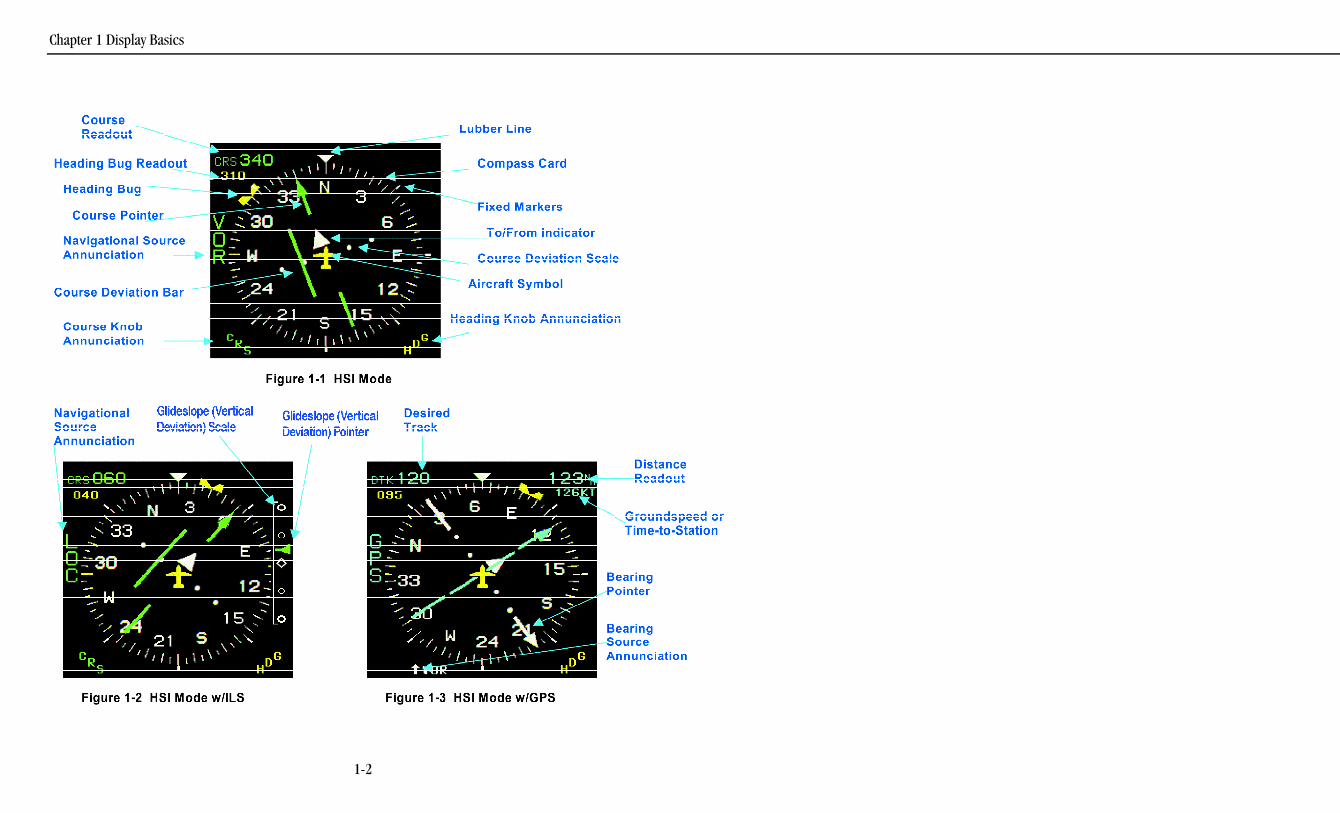
In HSI mode, the KI 825 displays navigational information in the standard360-degree compass format. The display contains information such ascompass card, navigational source indicator, heading bug, bearing pointer,course arrow with course deviation indicator, course readout, TO/FROMindicator, groundspeed and time-to-station, glideslope indicator (verticaldeviation), and error flags. While in HSI mode, the moving map and light-ning overlays are not available.
In 360 Map mode, the KI 825 displays navigational information in a 360-degree compass format. The same navigational information that isavailable in HSI mode is displayed except there is no course arrow andthe CDI is moved to the bottom of the display. In addition, the KI 825 candisplay GPS moving map information, including flight plan and direct towaypoints, course lines, and map scale. The lightning overlay may also bedisplayed while in this mode.
In Arc Map mode, the KI 825 displays the same information as it does inthe 360 Map mode but the display only shows approximately 45 degreeseach side of aircraft heading.
1.1 HSI MODE
This section describes the contents of the HSI mode and the elementscommon to 360 Map and Arc Map modes. The HSI mode is an electronicrepresentation of a standard electromechanical HSI. While in HSI mode,the moving map and lightning overlays are not available. Figures 1-1 to 1-3 are on a foldout page for reference as the section is being reviewed.
1.1.1 COMPASS CARD
A 360-degree rotating compass card indicates aircraft heading. The head-ing is shown with respect to magnetic north. A fixed yellow symbolicaircraft in the center of the compass card indicates the aircraft’s relation-ship to the horizontal situation display. The compass card is divided into5-degree increments with the 10-degree divisions being longer to help withidentification of the current heading. Fixed 45-degree markers are posi-tioned around the outside of the compass card.
KI 825 Pilot’s Guide Chapter 1 Display Basics
1-3
1.1.2 AIRCRAFT SYMBOL
The EHSI contains a fixed aircraft symbol at the center of the display. Thissymbol is for positional reference and serves the same purpose as thosecontained on mechanical HSI units. This symbol may be configured forfixed-wing aircraft or rotorcraft during installation.
1.1.3 LUBBER LINE
This line represents a heading reference index. This line is an extension ofthe nose of the fixed aircraft symbol and does not move.
1.1.4 PRIMARY NAVIGATIONAL SOURCE ANNUNCIATION
The navigation source selected by the pilot is annunciated vertically on theleft side of the display next to the compass card.
Two types of navigation sources are possible: VOR and GPS. When theselected navigational source is a VOR and a localizer frequency is tuned,the VOR annunciation will be changed to a LOC annunciation. Up to twoof each type of navigational sources can be annunciated.
The color of the navigational source annunciation will be cyan for GPS(when not in approach phase) and green for GPS (when in approachphase) and for VOR. The last course setting (before a navigational source change) is stored inthe indicator and recalled when the navigational source is reselected.(e.g., VOR is the selected navigational source with the course set at 300°.The navigational source is changed to GPS and the course changes to240°. When VOR is reselected as the navigational source, the coursereturns to 300° automatically). The EHSI does not differentiate betweenVOR1 and VOR2 or GPS1 and GPS2 when storing course settings.
(Software Versions –3 and -4 Only) The course storage feature describedin the previous paragraph may be disabled at the time of KI 825 installa-tion if the feature is not desired. The most common reason to have thisfeature disabled is to optimize the automatic GPS to ILS switching capabil-ity provided by units such as the Garmin GNS 430/530. When disabled,the course pointer doesn’t change position when switching between GPSand ILS navigation sensors.
Note 1: The EHSI’s ability to annunciate navigational source numerals(e.g., VOR 1, VOR 2, GPS 1, GPS 2) is dependent on the number andtype of each navigational source as well as the method used to interfacethe navigational sources to the KI 825.
Chapter 1 Display Basics KI 825 Pilot’s Guide
1-4
Note 2: The EHSI may not display a primary navigational source annunci-ation if the aircraft is configured to utilize external relay switching insteadof utilizing the KI 825’s internal switching.
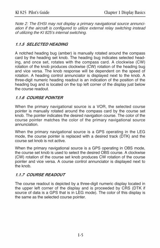
1.1.5 SELECTED HEADING
A notched heading bug (amber) is manually rotated around the compasscard by the heading set knob. The heading bug indicates selected head-ing, and once set, rotates with the compass card. A clockwise (CW)rotation of the knob produces clockwise (CW) rotation of the heading bugand vice versa. The knob response will be dependent on the speed ofrotation. A heading control annunciator is displayed next to the knob. Athree-digit numeric heading readout is an indication of the position of theheading bug and is located on the top left corner of the display just belowthe course readout.
1.1.6 COURSE POINTER
When the primary navigational source is a VOR, the selected coursepointer is manually rotated around the compass card by the course setknob. The pointer indicates the desired navigation course. The color of thecourse pointer matches the color of the primary navigational sourceannunciation.
When the primary navigational source is a GPS operating in the LEGmode, the course pointer is replaced with a desired track (DTK) and thecourse set knob is not active.
When the primary navigational source is a GPS operating in OBS mode,the course set knob is used to select the desired OBS course. A clockwise(CW) rotation of the course set knob produces CW rotation of the coursepointer and vice versa. A course control annunciator is displayed next tothe knob.
1.1.7 COURSE READOUT
The course readout is depicted by a three-digit numeric display located inthe upper left corner of the display and is proceeded by CRS (DTK ifsource of data is a GPS that is in LEG mode). The color of this display isthe same as the selected course pointer.
KI 825 Pilot’s Guide Chapter 1 Display Basics
1-5
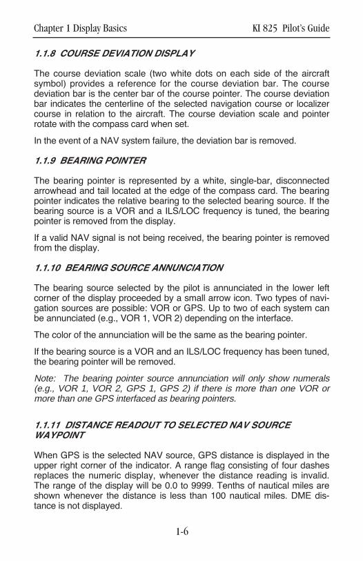
1.1.8 COURSE DEVIATION DISPLAY
The course deviation scale (two white dots on each side of the aircraftsymbol) provides a reference for the course deviation bar. The coursedeviation bar is the center bar of the course pointer. The course deviationbar indicates the centerline of the selected navigation course or localizercourse in relation to the aircraft. The course deviation scale and pointerrotate with the compass card when set.
In the event of a NAV system failure, the deviation bar is removed.
1.1.9 BEARING POINTER
The bearing pointer is represented by a white, single-bar, disconnectedarrowhead and tail located at the edge of the compass card. The bearingpointer indicates the relative bearing to the selected bearing source. If thebearing source is a VOR and a ILS/LOC frequency is tuned, the bearingpointer is removed from the display.
If a valid NAV signal is not being received, the bearing pointer is removedfrom the display.
1.1.10 BEARING SOURCE ANNUNCIATION
The bearing source selected by the pilot is annunciated in the lower leftcorner of the display proceeded by a small arrow icon. Two types of navi-gation sources are possible: VOR or GPS. Up to two of each system canbe annunciated (e.g., VOR 1, VOR 2) depending on the interface.
The color of the annunciation will be the same as the bearing pointer.
If the bearing source is a VOR and an ILS/LOC frequency has been tuned,the bearing pointer will be removed.
Note: The bearing pointer source annunciation will only show numerals(e.g., VOR 1, VOR 2, GPS 1, GPS 2) if there is more than one VOR ormore than one GPS interfaced as bearing pointers.
1.1.11 DISTANCE READOUT TO SELECTED NAV SOURCEWAYPOINT
When GPS is the selected NAV source, GPS distance is displayed in theupper right corner of the indicator. A range flag consisting of four dashesreplaces the numeric display, whenever the distance reading is invalid.The range of the display will be 0.0 to 9999. Tenths of nautical miles areshown whenever the distance is less than 100 nautical miles. DME dis-tance is not displayed.
Chapter 1 Display Basics KI 825 Pilot’s Guide
1-6
KI 825 Pilot’s Guide Chapter 1 Display Basics
1-7
1.1.12 DISTANCE READOUT TO SELECTED BEARING SOURCEWAYPOINT
When GPS is the selected navigational source for the bearing pointer, dis-tance is displayed in the lower right corner of the indicator. A range flagconsisting of four dashes replaces the numeric whenever the distancereading is invalid. The range of the display will be 0.0 to 9999. Tenths ofnautical miles will be shown whenever the distance is less than 100 nauti-cal miles. DME distance is not displayed.
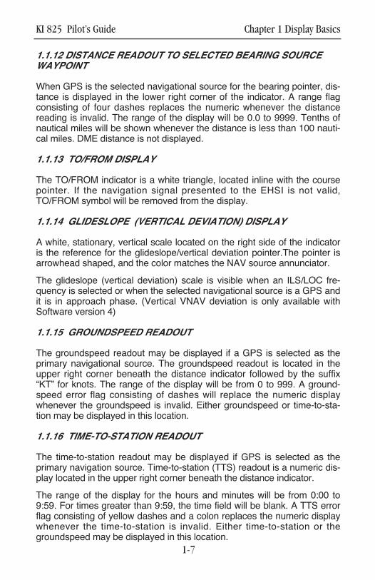
1.1.13 TO/FROM DISPLAY
The TO/FROM indicator is a white triangle, located inline with the coursepointer. If the navigation signal presented to the EHSI is not valid,TO/FROM symbol will be removed from the display.
1.1.14 GLIDESLOPE (VERTICAL DEVIATION) DISPLAY
A white, stationary, vertical scale located on the right side of the indicatoris the reference for the glideslope/vertical deviation pointer.The pointer isarrowhead shaped, and the color matches the NAV source annunciator.
The glideslope (vertical deviation) scale is visible when an ILS/LOC fre-quency is selected or when the selected navigational source is a GPS andit is in approach phase. (Vertical VNAV deviation is only available withSoftware version 4)
1.1.15 GROUNDSPEED READOUT
The groundspeed readout may be displayed if a GPS is selected as theprimary navigational source. The groundspeed readout is located in theupper right corner beneath the distance indicator followed by the suffix“KT” for knots. The range of the display will be from 0 to 999. A ground-speed error flag consisting of dashes will replace the numeric displaywhenever the groundspeed is invalid. Either groundspeed or time-to-sta-tion may be displayed in this location.
1.1.16 TIME-TO-STATION READOUT
The time-to-station readout may be displayed if GPS is selected as theprimary navigation source. Time-to-station (TTS) readout is a numeric dis-play located in the upper right corner beneath the distance indicator.
The range of the display for the hours and minutes will be from 0:00 to9:59. For times greater than 9:59, the time field will be blank. A TTS errorflag consisting of yellow dashes and a colon replaces the numeric displaywhenever the time-to-station is invalid. Either time-to-station or thegroundspeed may be displayed in this location.

Chapter 1 Display Basics KI 825 Pilot’s Guide
1-8
This page left blank intentionally.

KI 825 Pilot’s Guide Chapter 1 Display Basics
1-9
This page left blank intentionally.
Chapter 1 Display Basics KI 825 Pilot’s Guide
1-10
TRIM

KI 825 Pilot’s Guide Chapter 1 Display Basics
1-11
This page left blank intentionally.
Chapter 1 Display Basics KI 825 Pilot’s Guide
1-12
TRIM
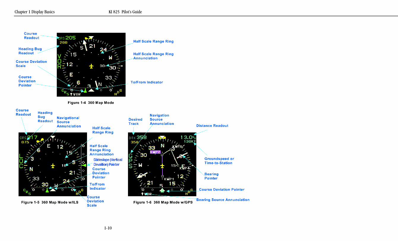
1.2 360 MAP MODE
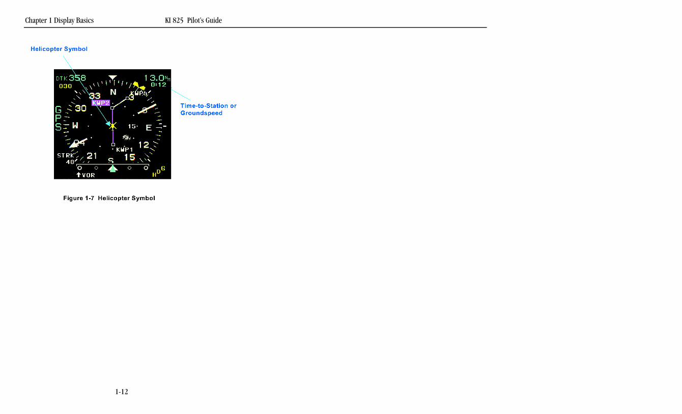
This section outlines differences between 360 Map mode and HSI mode.The 360 Map mode allows the presentation of lightning information (from aGoodrich WX-500 Stormscope® (if interfaced) and GPS moving map. Thelightning overlay is fully described in Sections 1.4 and 2.10. Figures 1-4 to1-7 are on a foldout page for reference as the section is being reviewed.
1.2.1 MAP MODE SELECTED COURSE
The numeric selected course readout in the upper left corner of the displayfunctions the same in the 360 Map mode as in the HSI mode.
When the selected NAV source is GPS (operating in the LEG mode), thedirect-to-waypoints and active flight plan are displayed on the map.
If the primary NAV sensor is GPS operating in OBS mode, and if theactive waypoints are within the selected map range, the selected courseline is drawn through the waypoint’s center. As the selected course ischanged, the course line will rotate about the waypoint.
If the primary NAV sensor is a GPS and the navigation informationbecomes invalid, the waypoint symbol and course line, are removed. Nomoving map is displayed when insufficient data is present to calculate andplot the primary NAV sensor map.
No navigation information is displayed on the moving map when VOR isselected as the primary navigation source. Lightning information may stillbe displayed when VOR is selected as the primary navigation source.
1.2.2 360 MAP COURSE DEVIATION INDICATOR
A stationary white scale along the bottom center of the display providesreference for the course deviation pointer to indicate the position of the air-craft in relation to the navigation course. This deviation scale provides aconventional CDI presentation.
1.2.3 TO/FROM DISPLAY
The center indicator of the course deviation scale becomes the TO/FROMindicator. A white up arrowhead indicates TO, and a white down arrow-head indicates FROM. If the TO/FROM signal input is in not valid, theTO/FROM indicator is removed and the center indicator changes to awhite, unfilled diamond.
KI 825 Pilot’s Guide Chapter 1 Display Basics
1-13
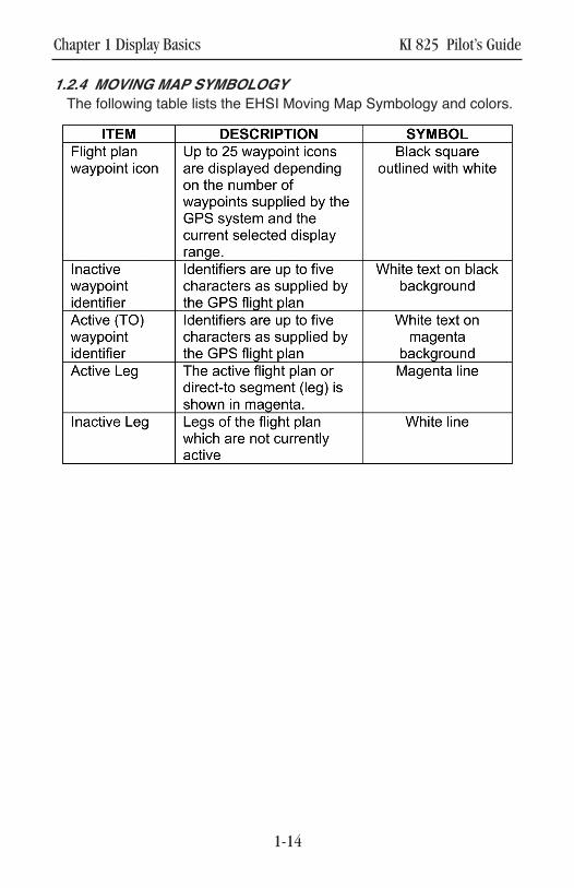
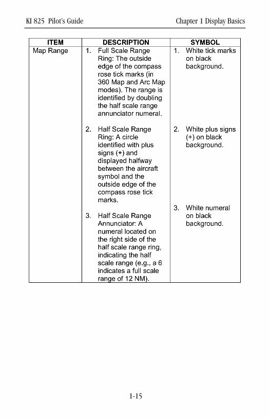
1.2.4 MOVING MAP SYMBOLOGY
The following table lists the EHSI Moving Map Symbology and colors.
Chapter 1 Display Basics KI 825 Pilot’s Guide
1-14
KI 825 Pilot’s Guide Chapter 1 Display Basics
1-15

This page left blank intentionally.
Chapter 1 Display Basics KI 825 Pilot’s Guide
1-16

KI 825 Pilot’s Guide Chapter 1 Display Basics
1-17
This page left blank intentionally.
Chapter 1 Display Basics
1-18
TRIM

KI 825 Pilot’s Guide Chapter 1 Display Basics
1-19
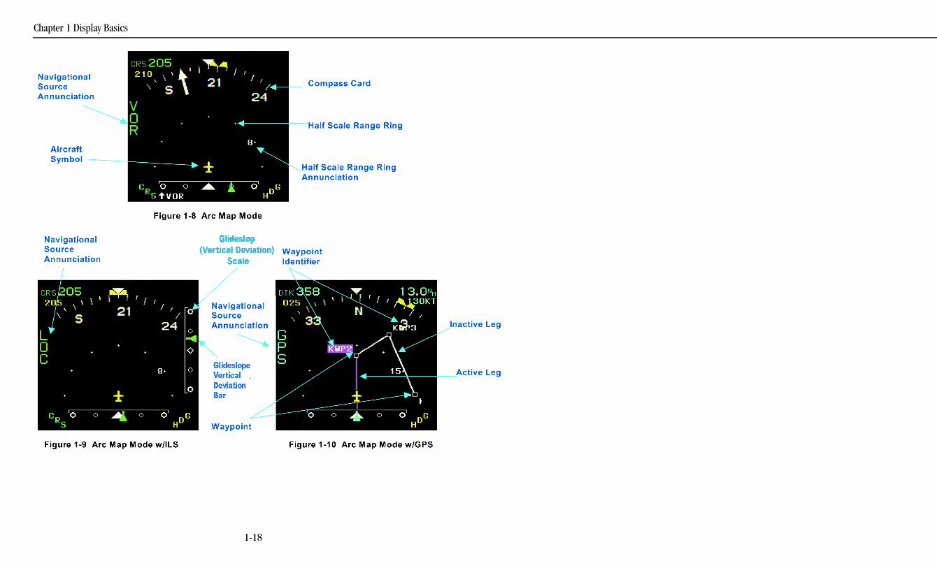
1.3 ARC MAP MODE
The Arc Map mode is an exploded view of the 360 Map mode, but only45° either side of the aircraft heading is visible, providing enhanced view-ing and ease of reading when displaying multifunction features. The ArcMap mode range ring operates the same as in the 360 Map mode, withthe only exception being that seven range dots are visible. The lightningoverlay is fully described in Section 1.4 and 2.10. Figures 1-8 to 1-10 areon a foldout page for reference as the section is being reviewed.

Chapter 1 Display Basics KI 825 Pilot’s Guide
1-20
This page left blank intentionally.

KI 825 Pilot’s Guide Chapter 1 Display Basics
1-21
This page left blank intentionally.
Chapter 1 Display Basics
1-22
TRIM
KI 825 Pilot’s Guide Chapter 1 Display Basics
1-23
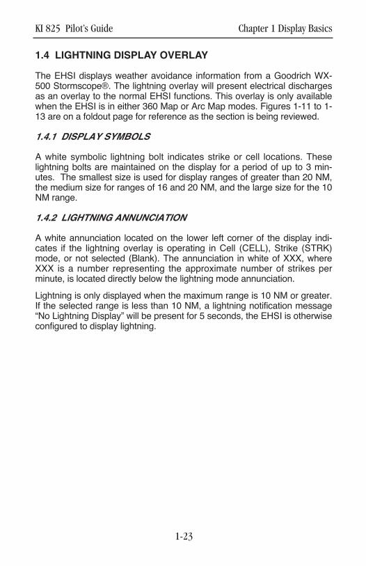
1.4 LIGHTNING DISPLAY OVERLAY
The EHSI displays weather avoidance information from a Goodrich WX-500 Stormscope®. The lightning overlay will present electrical dischargesas an overlay to the normal EHSI functions. This overlay is only availablewhen the EHSI is in either 360 Map or Arc Map modes. Figures 1-11 to 1-13 are on a foldout page for reference as the section is being reviewed.
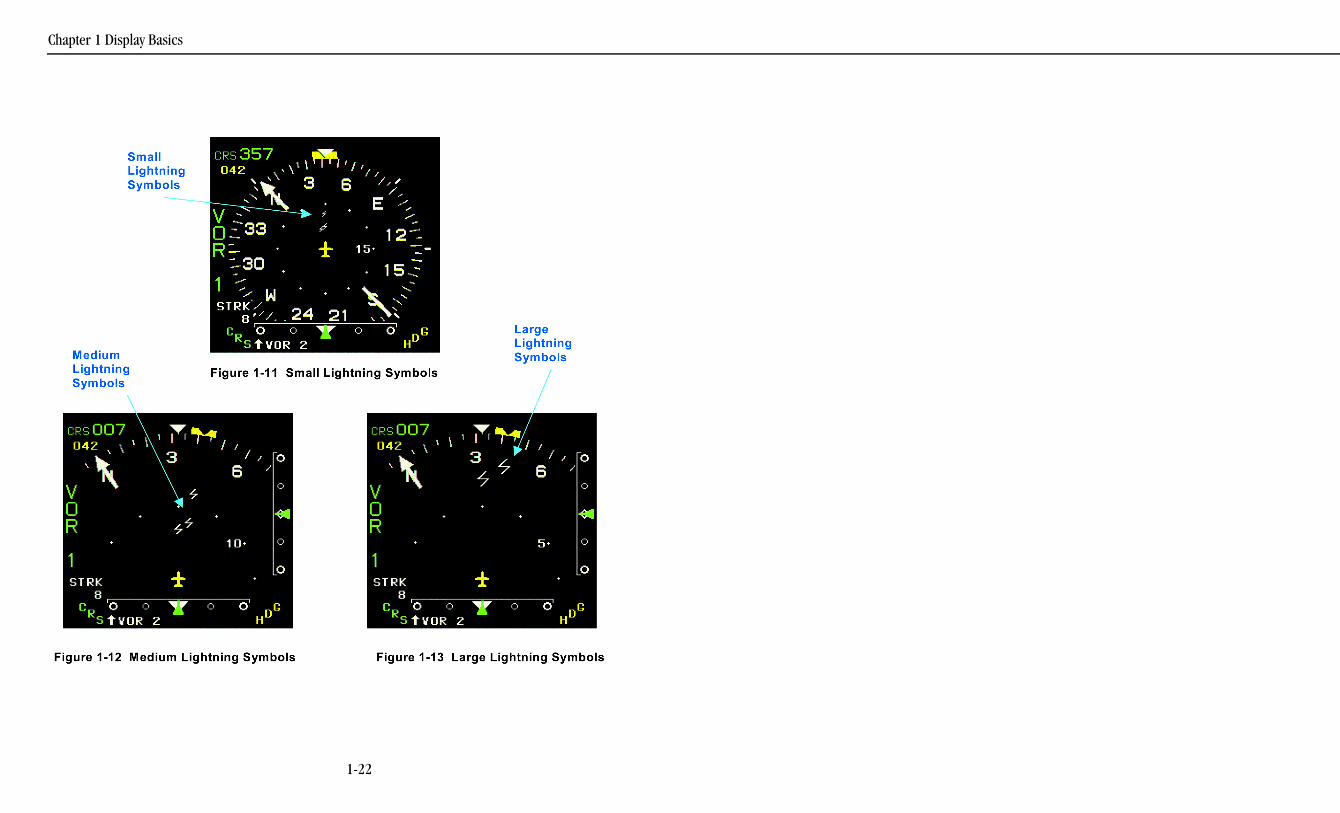
1.4.1 DISPLAY SYMBOLS
A white symbolic lightning bolt indicates strike or cell locations. Theselightning bolts are maintained on the display for a period of up to 3 min-utes. The smallest size is used for display ranges of greater than 20 NM,the medium size for ranges of 16 and 20 NM, and the large size for the 10NM range.
1.4.2 LIGHTNING ANNUNCIATION
A white annunciation located on the lower left corner of the display indi-cates if the lightning overlay is operating in Cell (CELL), Strike (STRK)mode, or not selected (Blank). The annunciation in white of XXX, whereXXX is a number representing the approximate number of strikes perminute, is located directly below the lightning mode annunciation.
Lightning is only displayed when the maximum range is 10 NM or greater.If the selected range is less than 10 NM, a lightning notification message“No Lightning Display” will be present for 5 seconds, the EHSI is otherwiseconfigured to display lightning.

This page left blank intentionally.
Chapter 1 Display Basics KI 825 Pilot’s Guide
1-24

KI 825 Pilot’s Guide Chapter 2 Buttons, Knobs and Menu Options
2-1
This page left blank intentionally.

KI 825 Pilot’s GuideChapter 2 Buttons, Knobs and Menu Options
2-2
HeadingSetKnob
CourseSet
Knob
Menu Button
Figure 2-1 Operating Controls
TRIM
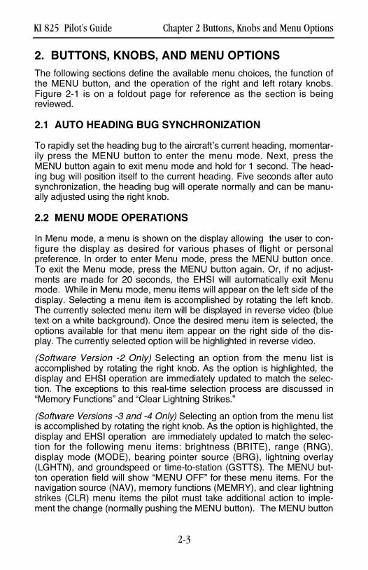
2. BUTTONS, KNOBS, AND MENU OPTIONSThe following sections define the available menu choices, the function ofthe MENU button, and the operation of the right and left rotary knobs.Figure 2-1 is on a foldout page for reference as the section is beingr e v i e w e d .
2.1 AUTO HEADING BUG SYNCHRONIZATION
To rapidly set the heading bug to the aircraft’s current heading, momentar-ily press the MENU button to enter the menu mode. Next, press theMENU button again to exit menu mode and hold for 1 second. The head-ing bug will position itself to the current heading. Five seconds after autosynchronization, the heading bug will operate normally and can be manu-ally adjusted using the right knob.
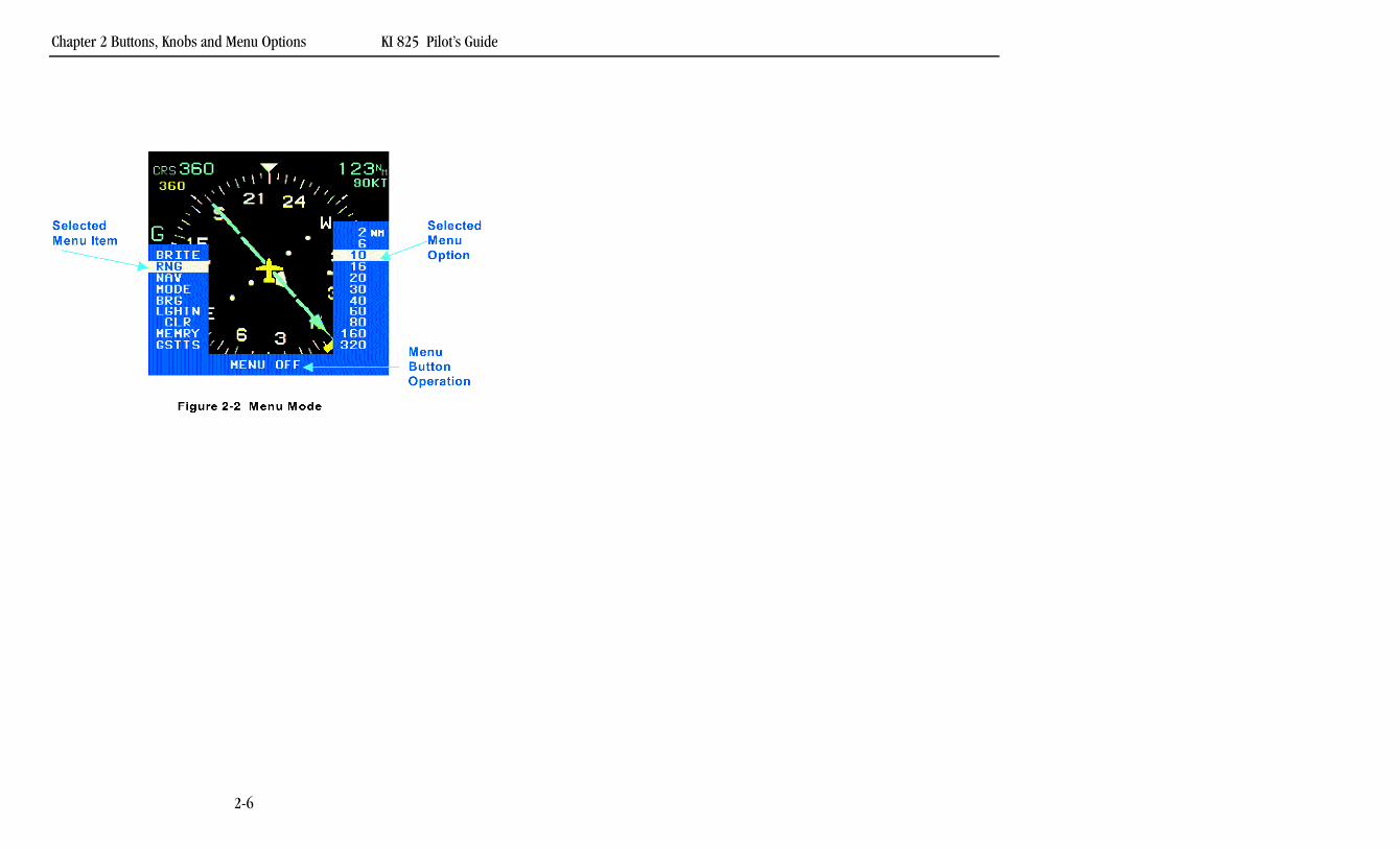
2.2 MENU MODE OPERATIONS
In Menu mode, a menu is shown on the display allowing the user to con-figure the display as desired for various phases of flight or personalpreference. In order to enter Menu mode, press the MENU button once.To exit the Menu mode, press the MENU button again. Or, if no adjust-ments are made for 20 seconds, the EHSI will automatically exit Menumode. While in Menu mode, menu items will appear on the left side of thedisplay. Selecting a menu item is accomplished by rotating the left knob.The currently selected menu item will be displayed in reverse video (bluetext on a white background). Once the desired menu item is selected, theoptions available for that menu item appear on the right side of the dis-play. The currently selected option will be highlighted in reverse video. (Software Version -2 Only) Selecting an option from the menu list isaccomplished by rotating the right knob. As the option is highlighted, thedisplay and EHSI operation are immediately updated to match the selec-tion. The exceptions to this real-time selection process are discussed in“Memory Functions” and “Clear Lightning Strikes.”
(Software Versions -3 and -4 Only) Selecting an option from the menu listis accomplished by rotating the right knob. As the option is highlighted, thedisplay and EHSI operation are immediately updated to match the selec-tion for the following menu items: brightness (BRITE), range (RNG),display mode (MODE), bearing pointer source (BRG), lightning overlay(LGHTN), and groundspeed or time-to-station (GSTTS). The MENU but-ton operation field will show “MENU OFF” for these menu items. For thenavigation source (NAV), memory functions (MEMRY), and clear lightningstrikes (CLR) menu items the pilot must take additional action to imple-ment the change (normally pushing the MENU button). The MENU button
KI 825 Pilot’s Guide Chapter 2 Buttons, Knobs and Menu Options
2-3

operation field will show “Press To Select” or “Press to Clear” as a promptto press the MENU button. See “Navigation Source” (section 2.7),“Memory Functions” (section 2.12), and “Clear Lightning Strikes” (section2.11) for additional details.
Chapter 2 Buttons, Knobs and Menu Options KI 825 Pilot’s Guide
2-4

KI 825 Pilot’s Guide Chapter 2 Buttons, Knobs and Menu Options
2-5
This page left blank intentionally.
Chapter 2 Buttons, Knobs and Menu Options KI 825 Pilot’s Guide
2-6
TRIM
2.3 MENU DYNAMICS
A menu selection will not be displayed if it is not available due to the con-figuration of the aircraft. For example, if the instrument is not configured tointerface with a Goodrich WX-500 Stormscope®, the Lightning mode andClear Lightning Strikes menu items will not be shown. Figure 2-2 is on afoldout page for reference as the section is being reviewed.
If a menu selection is not available due to current menu choices, it will bedisplayed but it will be cyan (light blue) lettering with a blue background,indicating that function is disabled. For example, if the selected displaymode is HSI mode, the range has no effect and will consequently be dis-abled (e.g., RNG is shown in cyan). Once a change has been made whichallows a function to be available for the new setup, the menu items will beenabled. Menu choices that are available will be displayed in white letter-ing with a blue background.
Even though the lightning overlay is only allowed during the two mapmodes, the lightning menu item will always be available if a Goodrich WX-500 Stormscope® is interfaced to the KI 825. If the lightning menu item isselected while the current mode is set to HSI, the unit will automaticallyswitch the mode to 360 Map.(Software Version -2 Only) The Menu Button operation field will showMENU OFF for all menu items, with two exceptions: The Memory menuitem, when a SAVE menu option is currently selected, in which case it willshow HOLD FOR SAVE; and the “Clear Lightning Strikes” item, in whichcase it will show “Press to Clear”.
(Software Versions -3 and -4 Only) The MENU button operation fieldappears above the MENU button when the menu is being displayed toindicate the function of the button. It can show several different promptsdepending on the situation. In most instances it displays “MENU OFF” toindicate that pressing the MENU button removes the menu from the dis-play. The MENU button operation field will show “Press To Select” when itis necessary to press the MENU button to complete a selection. This isrequired when changing the navigation source or utilizing the LOAD mem-ory function. The MENU button operation field will show “HOLD FORSAVE” when the SAVE memory function is being used. The MENU buttonoperation field will show “Press to Clear” when the “Clear LightningStrikes” menu item has been selected.
KI 825 Pilot’s Guide Chapter 2 Buttons, Knobs and Menu Options
2-7
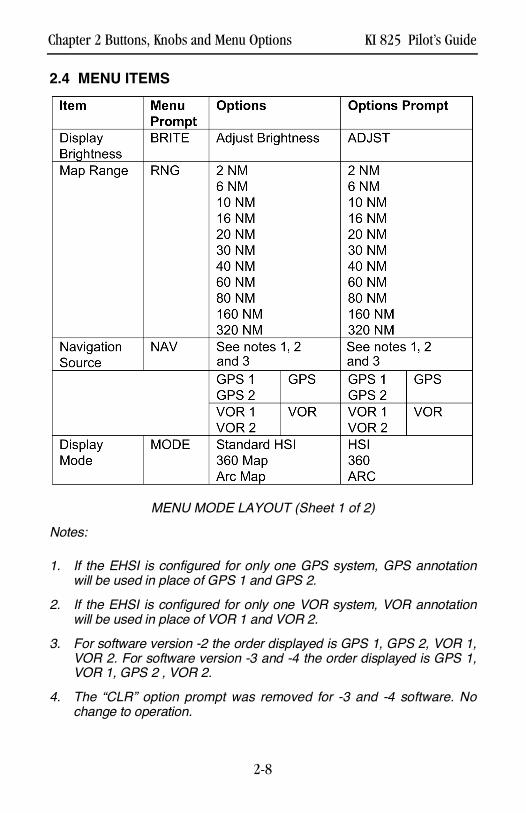
2.4 MENU ITEMS
MENU MODE LAYOUT (Sheet 1 of 2)N o t e s :
1 . If the EHSI is configured for only one GPS system, GPS annotationwill be used in place of GPS 1 and GPS 2.
2 . If the EHSI is configured for only one VOR system, VOR annotationwill be used in place of VOR 1 and VOR 2.
3 . For software version -2 the order displayed is GPS 1, GPS 2, VOR 1,VOR 2. For software version -3 and -4 the order displayed is GPS 1,VOR 1, GPS 2 , VOR 2.
4 . The “CLR” option prompt was removed for -3 and -4 software. Nochange to operation.
Chapter 2 Buttons, Knobs and Menu Options KI 825 Pilot’s Guide
2-8
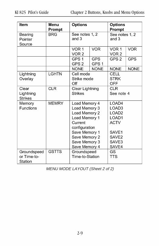
MENU MODE LAYOUT (Sheet 2 of 2)
KI 825 Pilot’s Guide Chapter 2 Buttons, Knobs and Menu Options
2-9
2.5 DISPLAY BRIGHTNESS (BRITE)
The brightness of the display may be adjusted from this menu item byturning the right knob clockwise to increase brightness and counterclock-wise to decrease brightness.
NOTE: When power is first applied to the unit, it “wakes up” with the dis -play brightness set to whichever of the following is the brightest: (1) thebrightness selected prior to the last power down or (2) a low-level factorydefault setting.
There is also a shortcut to the display brightness adjustment menu item:With the EHSI n o t in the Menu mode, press and hold the MENU button for2 seconds to permit adjustment of the display brightness.
(Software Versions –3 and -4 Only) If an aircraft has a day/night switchused for dimming annunciators and displays at night, the KI 825 may havebeen connected to this switch at the time of installation. If connected, thebrightness of the display is adjusted from the BRITE menu item in the nor-mal manner. However, there is a separate brightness adjust range for theday position and another, dimmer range for the night position. If the KI 825is not connected to a day/night switch it operates as described in the para-graphs above.
2.6 RANGE (RNG)
The Range menu allows the selection of the display range used in the 360Map or the Arc Map display modes. If the range is less than 10 and alightning overlay is being shown, the unit will announce NO LIGHTNING.
2.7 NAVIGATION SOURCE (NAV)
The Navigation Source menu allows the selection of the primary naviga-tion source.
(Software Versions –3 and -4 Only) When the right knob has been used toselect the desired navigation source the pilot must take one of the follow-ing actions to implement the change:
• Press the MENU button to select the navigation source and turn off themenu mode.
O r• Turn the left knob to select another menu item (other than NAV) from
the list.
Note: If one of the above actions is not taken, the display will return to thepreviously selected navigation sensor when the menu times out after 20s e c o n d s .
Chapter 2 Buttons, Knobs and Menu Options KI 825 Pilot’s Guide
2-10
Note: See also section 2.14 for an alternate means of changing the navi-gation source.
2.8 DISPLAY MODE (MODE)
The display mode menu item allows the selection of the current displaymode. Menu options include:
• HSI mode - Displays standard HSI information in a 360-degree viewabout the aircraft and acts as a standard HSI display. If the displaymode is changed to HSI Mode while the lightning overlay is shown,the unit will annunciate NO TRFC/LGHTN.
• 360 Map mode - Displays navigational information in a 360-degreeview about the aircraft, including GPS map information for direct-toand active flight plan waypoints. The lightning overlay may also bedisplayed in this mode.
• Arc Map mode - Displays an exploded view of the 360 Map mode,but only 45 degrees either side of the aircraft heading is visible. Thelightning overlay may also be displayed while in this mode.
2.9 BEARING POINTER SOURCE (BRG)
The Bearing Pointer Source menu item allows the selection of the bearingpointer source.
2.10 LIGHTNING OVERLAY (LGHTN)
The lightning overlay is available only if the EHSI is configured with aGoodrich WX-500 Stormscope®. The lightning menu allows the selectionof the lightning overlay.
If the LGHTN menu item is selected while in HSI mode, the option on theright is initially blank. If the lightning option is changed to CELL or STRKmode, the EHSI will automatically change the display mode to 360 Mapmode and will annunciate MODE CHANGED. If the range is less then 10NM and lightning mode is in cell or strike, NO LIGHTNING is annunciated.This annunciation takes precedence over the MODE CHANGED annunci-ation.
The lightning overlay menu item contains three options:
• Cell mode - The EHSI displays clusters of electrical activity indicat-ing storm cell areas.
• Strike mode - The EHSI displays individual electrical discharges.
KI 825 Pilot’s Guide Chapter 2 Buttons, Knobs and Menu Options
2-11
• Off - Lightning overlay is not displayed.NOTE: Refer to the Goodrich WX-500 Stormscope® operator’s manualfor additional information on Cell and Strike modes.
2.11 CLEAR LIGHTNING STRIKES (CLR)
Pressing the MENU button when the Clear Lightning Strikes is currentlyselected clears all existing discharge points being displayed.
Note: If another indicator (e.g., a KMD850) is the master display for theGoodrich WX-500 Stormscope®, the lightning icons can only be clearedfrom the KI 825 with an external switch (optional).
2.12 MEMORY FUNCTIONS (MEMRY)
The Memory menu item allows the pilot to save up to four unique displayconfigurations and recall them for use at a later time. For example, thepilot may have a specific display setup for ILS approach, another for GPSapproach, another for en route, etc.
The SAVE menu option allows for saving the current range, navigationsource, display mode, bearing indicator source, and lightning overlay. Tosave the current configuration to a memory location, highlight the desiredSAVE menu option (e.g., SAVE1, SAVE2) and then press and hold theMENU button for 2 seconds. Saved configurations are stored in memoryto maintain the setups even when the EHSI is powered off.
(Software Version –2 Only) To activate a previously saved configuration,select the appropriate LOAD number that corresponds to the SAVE num-ber used to store the setup (e.g., LOAD1, LOAD2, etc.). The ACTV menuoption returns the display setup to the state it was in before entering theMemory menu item. The unit will change immediately to the desired con-figuration when a LOAD or ACTV menu item is selected.
(Software Versions –3 and -4 Only) To activate a previously saved config-uration, select the appropriate LOAD number that corresponds to theSAVE number used to store the setup (e.g., LOAD1, LOAD2, etc.). Toimplement the changed configuration the pilot must take one of the follow-ing two actions:
• Press the MENU button to select the desired configuration andturn off the menu mode
O r• Turn the left knob to select another menu item (other than
MEMRY) from the list.
Chapter 2 Buttons, Knobs and Menu Options KI 825 Pilot’s Guide
2-12
Note: If one of the above actions is not taken, the display will return to thepreviously selected configuration state when the menu times out after 20s e c o n d s .
The ACTV menu option may be used to return the display setup to thestate it was in before entering the Memory menu item.
2.13 GROUNDSPEED OR TIME-TO-STATION (GSTTS)
The groundspeed or time-to-station menu item allows the pilot to displaythe groundspeed or the time-to-station, if available. This menu item is dis-abled if the selected navigation source is not a GPS.
2.14 (SOFTWARE VERSIONS –3 AND -4 ONLY) OPTIONALNAVIGATION SOURCE SELECT SWITCH
A momentary push button switch may be installed in the aircraft’s instru-ment panel to toggle the selected navigation source between GPS andNAV. If the KI 825 installation is interfaced with GPS 1, VOR 1, GPS 2and VOR 2, pressing the switch only toggles between the sensors of theselected system. Therefore if GPS 1 is selected on the KI 825, pressingthe push button toggles between GPS 1 and VOR 1. If GPS 2 is selected,pressing the push button toggles between GPS 2 and VOR 2.
2.15 (SOFTWARE VERSIONS –3 AND -4 ONLY) OPERA-TIONAL CHARACTERISTICS OF A SINGLE KI 825 WITHDUAL GARMIN GNS 430 (OR 530) INSTALLATION
The following operational characteristics apply to an installation consistingof a single KI 825 EHSI, two Garmin GNS 430 (or 530) integratedNav/Com/GPS units, and a single mechanical course deviation indicator(CDI). The mechanical CDI displays navigation information from the # 2GNS 430 system only. The characteristics described below are applicablewhen the equipment is installed in accordance with the current revision ofthe Bendix/King KI 825 Installation Manual for this equipment.
1 . GPS 1, VOR 1, GPS 2 and VOR 2 can be selected as the navigationsource using the menu on the KI 825. All four selections are alsoavailable for the bearing pointer. The GPS/VLOC annunciation on theGarmin GNS 430 will change consistently with the selection madefrom the KI 825. For example, when GPS 1 is selected on the KI 825the #1 GNS 430 system will annunciate “GPS”. When VOR 2 isselected on the KI 825, the #2 GNS 430 will annunciate “VLOC”.
KI 825 Pilot’s Guide Chapter 2 Buttons, Knobs and Menu Options
2-13
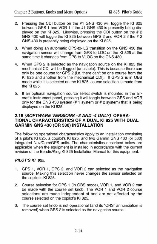
2 . Pressing the CDI button on the #1 GNS 430 will toggle the KI 825between GPS 1 and VOR 1 if the #1 GNS 430 is presently being dis-played on the KI 825. Likewise, pressing the CDI button on the # 2GNS 430 will toggle the KI 825 between GPS 2 and VOR 2 if the # 2GNS 430 is presently being displayed on the KI 825.
3 . When doing an automatic GPS-to-ILS transition on the GNS 430 thenavigation sensor will change from GPS to LOC on the KI 825 at thesame time it changes from GPS to VLOC on the GNS 430.
4 . When GPS 2 is selected as the navigation source on the KI 825 themechanical CDI will be flagged (unusable). This is because there canonly be one course for GPS 2 (i.e. there can’t be one course from theKI 825 and another from the mechanical CDI). If GPS 2 is in OBSmode while it is selected on the KI 825, course selection is made fromthe KI 825.
5 . If an optional navigation source select switch is mounted in the air-craft’s instrument panel, pressing it will toggle between GPS and VORonly for the GNS 430 system (# 1 system or # 2 system) that is beingdisplayed on the KI 825.
2.16 (SOFTWARE VERSIONS –3 AND -4 ONLY) OPERA-TIONAL CHARACTERISTICS OF A DUAL KI 825 WITH DUALGARMIN GNS 430 (OR 530) INSTALLATION
The following operational characteristics apply to an installation consistingof a pilot’s KI 825, a copilot’s KI 825, and two Garmin GNS 430 (or 530)integrated Nav/Com/GPS units. The characteristics described below areapplicable when the equipment is installed in accordance with the currentrevision of the Bendix/King KI 825 Installation Manual for this equipment.
PILOT’S KI 825.
1 . GPS 1, VOR 1, GPS 2, and VOR 2 can selected as the navigationsource. Making this selection never changes the sensor selected onthe copilot’s KI 825.
2 . Course selection for GPS 1 (in OBS mode), VOR 1, and VOR 2 canbe made with the course set knob. The VOR 1 and VOR 2 courseselections are made independent of and are not affected by thecourse selected on the copilot’s KI 825.
3 . The course set knob is not operational (and its “CRS” annunciation isremoved) when GPS 2 is selected as the navigation source.
Chapter 2 Buttons, Knobs and Menu Options KI 825 Pilot’s Guide
2-14
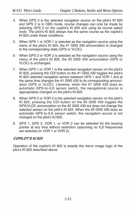
4. When GPS 2 is the selected navigation source on the pilot’s KI 825and GPS 2 is in OBS mode, course changes can only be made byselecting GPS 2 on the copilot’s KI 825 and using its course selectknob. The pilot’s KI 825 always has the same course as the copilot’sKI 825 under these conditions.
5. When GPS 1 or VOR 1 is selected as the navigation source using themenu of the pilot’s KI 825, the #1 GNS 430 annunciation is changedto the corresponding state (GPS or VLOC).
6. When GPS 2 or VOR 2 is selected as the navigation source using themenu of the pilot’s KI 825, the #2 GNS 430 annunciation (GPS orVLOC) is unchanged.
7. When GPS 1 or VOR 1 is the selected navigation sensor on the pilot’sKI 825, pressing the CDI button on the #1 GNS 430 toggles the pilot’sKI 825 selected navigation sensor between GPS 1 and VOR 1 and atthe same time changes the #1 GNS 430 to its corresponding annunci-ation (GPS or VLOC). Likewise, when the #1 GNS 430 does anautomatic GPS-to-ILS sensor switch, the navigational source isappropriately changed on the pilot’s KI 825.
8. When GPS 2 or VOR 2 is the selected navigation sensor on the pilot’sKI 825, pressing the CDI button on the #2 GNS 430 toggles theGPS/VLOC annunciation on the #2 GNS 430 but does not change theselected sensor on the pilot’s KI 825. When the #2 GNS 430 does anautomatic GPS-to-ILS sensor switch, the navigation source is notchanged on the pilot’s KI 825.
9. GPS 1, GPS 2, VOR 1, or VOR 2 can be selected for the bearingpointer at any time without restriction (assuming no ILS frequenciesare selected on VOR 1 or VOR 2).
COPILOT’S KI 825
Operation of the copilot’s KI 825 is exactly the mirror image logic of thepilot’s KI 825 described above.
KI 825 Pilot’s Guide Chapter 2 Buttons, Knobs and Menu Options
2-15

This page left blank intentionally.
Chapter 2 Buttons, Knobs and Menu Options KI 825 Pilot’s Guide
2-16

KI 825 Pilot’s Guide Chapter 3 Error Flags and Warnings
3-1
This page left blank intentionally.
Chapter 3 Error Flags and Warnings KI 825 Pilot’s Guide
3-2
TRIM
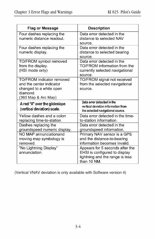
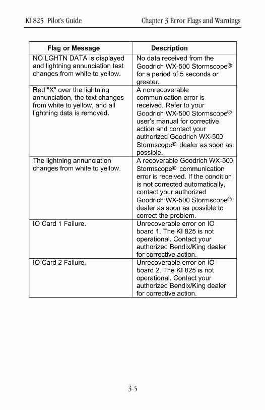
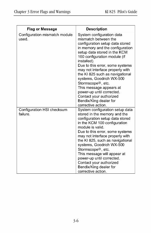
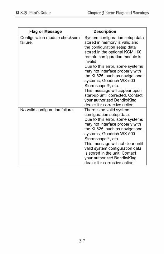
3. ERROR FLAGS AND WARNINGS
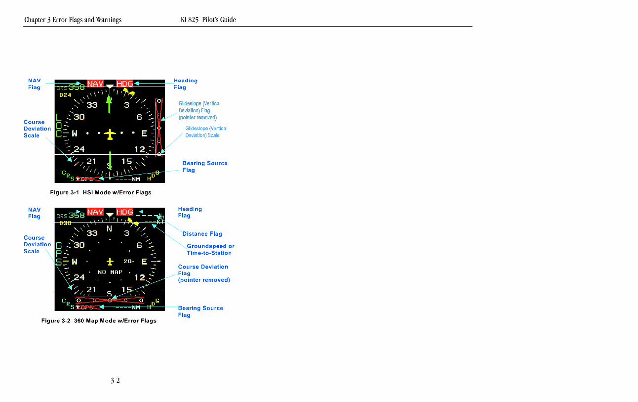
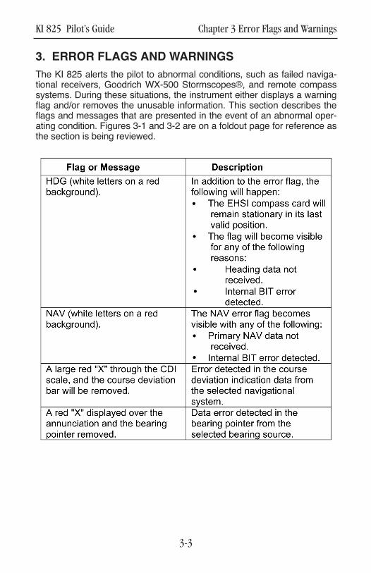
The KI 825 alerts the pilot to abnormal conditions, such as failed naviga-tional receivers, Goodrich WX-500 Stormscopes®, and remote compasssystems. During these situations, the instrument either displays a warningflag and/or removes the unusable information. This section describes theflags and messages that are presented in the event of an abnormal oper-ating condition. Figures 3-1 and 3-2 are on a foldout page for reference asthe section is being reviewed.
KI 825 Pilot’s Guide Chapter 3 Error Flags and Warnings
3-3
Chapter 3 Error Flags and Warnings KI 825 Pilot’s Guide
3-4
(Vertical VNAV deviation is only available with Software version 4)
KI 825 Pilot’s Guide Chapter 3 Error Flags and Warnings
3-5
Chapter 3 Error Flags and Warnings KI 825 Pilot’s Guide
3-6
KI 825 Pilot’s Guide Chapter 3 Error Flags and Warnings
3-7

This page left blank intentionally.
Chapter 3 Error Flags and Warnings KI 825 Pilot’s Guide
3-8
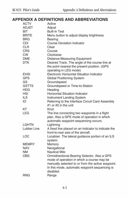
APPENDIX A DEFINITIONS AND ABBREVIATIONSACTV ActiveADJST AdjustBIT Built-In TestBRITE Menu button to adjust display brightnessBRG BearingCDI Course Deviation IndicatorCLR ClearCRS CourseCW ClockwiseDME Distance-Measuring EquipmentDTK Desired Track. The angle of the course line at
the point nearest the present position. (GPS operating in LEG mode)
EHSI Electronic Horizontal Situation IndicatorGPS Global Positioning SystemGS GroundspeedGSTTS Groundspeed or Time-to-StationHDG HeadingHSI Horizontal Situation IndicatorILS Instrument Landing SystemIO Referring to the Interface Circuit Card Assembly
#1 or #2 in the unitKT KnotLEG The line connecting two waypoints in a flight
plan. Also a GPS mode of operation in which automatic waypoint sequencing occurs.
LGHTN LightningLubber Line A fixed line placed on an indicator to indicate the
front-to-rear axis of the aircraft.LOC Localizer. The lateral guidance portion of an ILS
system.MEMRY MemoryNAV NavigationalNM Nautical MileOBS Omnidirectional Bearing Selector. Also a GPS
mode of operation in which a course may be manually selected to or from the active waypoint.In this mode, automatic waypoint sequencing is disabled.
RNG Range
KI 825 Pilot’s Guide Appendix A Definitions and Abreviations
A-1

S T R K Lightning StrikeT T S T i m e - t o - S t a t i o nV N A V Vertical NavigationV O R Very high frequency omnidirectional radio range
- a system that provides bearing information to an aircraft.
Appendix A Definitions and Abreviations KI 825 Pilot’s Guide
A-2

Honeywell International Inc.One Technology Center23500 West 105th StreetOlathe, Kansas 66061FAX 913-791-1302Telephone: (913) 712-0400
Copyright ©2002, 2004, 2008 Honeywell InternationalInc.All rights reserved.
006-18280-0000Rev 3 4/2008 N
KI 825 PG R2 Cover.qxd 4/16/08 5:08 PM Page 4