pinellas trail / roadway intersections evaluation ... policy9_1.pdf · pinellas trail / roadway...
TRANSCRIPT
Pinellas Trail / Roadway Intersections Evaluation
Assigning Priority and Determining Traffic Control at Shared Use Path / Roadway Intersections City of St. Petersburg
Report (Revised November 2010)
Prepared by: Theodore A. Petritsch Bruce W. Landis 18115 U.S. Highway 41, Suite 600 Lutz, Florida 33549 Certificate of Authorization # 4548
Evaluation and Recommendations for Roadway Page 2 of 27
Intersections along the Pinellas Trail - Rev 11/2010
I:\Transportation Planning\Neighborhood\CIP Projects\Pinellas Trail Intersection Control\Crossing policy 9_1.doc
INTRODUCTION
In St. Petersburg, Pinellas County, and across the country, there is an increasing concern that the
priority assigned to trail and roadway traffic at intersections and corresponding controls are not
being implemented consistently or with due consideration of the intersection traffic conditions.
This lack of a consistent methodology results in pathway and roadway users behaving
unpredictably at intersections. This, in turn, can cause crashes. For example, in many cases a
STOP sign (R1-1) sign is placed on the trail approaches “just to make sure” that pathway users
behave in a safe manner. Often, motorists on low speed or low volume roadways will yield to
users on the pathway; some even wave pathway users through the intersections. Consequently,
pathway users may come to expect this yielding behavior from motorists. Some motorists,
however, do not yield and surprise cyclists who expect to be able to ride through the intersection
without yielding. Alternatively, a path user may come to expect motorists to yield at other
intersections where motorists may be traveling faster and be less inclined to stop for path users.
Essentially, the put-STOP-signs-everywhere approach to pathway / roadway intersection control
leads to users ignoring the signs or failing to stop / yield when necessary. When overused or
placed inappropriately, STOP signs are not seen as fulfilling a real need. Consequently, they fail to
command the attention and respect of pathway users1. As users lose respect for the traffic control
devices placed on the pathway, the safety of the shared use pathway is compromised. This is
especially dangerous at locations where the R1-1 is warranted and non-compliance by some path
users creates a serious safety problem.
The Manual on Uniform Traffic Control Devices does not provide specific guidance on how to
sign and stripe pathway / roadway intersections. The AASHTO Guide for the Development of
Bicycle Facilities2 states only that intersection striping should be placed as warranted by the
MUTCD. Florida DOT design guidance3 reiterates what is in the MUTCD. This lack of guidance
contributes to the inconsistent and, in some cases, inappropriate, application of traffic control
devices at these intersections, which, in turn, results in unpredictable and potentially dangerous
behaviors on the part of motorists and path users.
This report presents guidelines developed to fill the gap in the existing State and National
guidance documents. It includes a methodology to determine which facility, the roadway or path,
should receive priority at an intersection. It then describes what traffic control treatments would be
appropriate at a midblock crossing of a roadway by a shared use path. It also provides background
into how the methodology was developed. It presents a proposed set of guidelines for providing
consistent crossing treatments to increase the safety and convenience of pathway users along trails
in St. Petersburg. Then this report discusses the eight existing Pinellas Trail / roadway
intersections in St. Petersburg and recommended modifications to those intersections that would
result from the application of these guidelines.
The guidelines presented and applied within this report represent a method to consistently apply
traffic control devices at path / roadway intersections. The guidelines should be applied to the
1 FHWA, Manual on Uniform Traffic Control Devices, Section 1A.02, FHWA, Washington, D.C., 2003.
2 AASHTO, Guide for the Development of Bicycle Facilities, pg. 47, AASHTO, Washington, D.C., 1999.
3 FDOT, Bicycle Facilities Planning and Design Handbook, FDOT, Tallahassee, FL, 2002.
Evaluation and Recommendations for Roadway Page 3 of 27
Intersections along the Pinellas Trail - Rev 11/2010
I:\Transportation Planning\Neighborhood\CIP Projects\Pinellas Trail Intersection Control\Crossing policy 9_1.doc
maximum extent possible to ensure the expectations of path and roadway users are met at all
intersections along the Pinellas Trail or other trails in St. Petersburg.
The Pinellas County MPO Traffic Signals and Median Control Committee have endorsed this
methodology. The text of that endorsement is provided at the end of this report.
BACKGROUND
The Pinellas County Metropolitan Planning Organization (MPO) recently performed an evaluation
of the roadway / pathway intersections along the Pinellas Trail. This report included a “Trail
Crossing Inventory by Jurisdiction” and recommendations on what modifications to existing
traffic control devices should be made at each intersection. The methodology used to develop the
recommendations included inventorying the existing traffic control devices, traffic conditions,
sight distances and other data pertinent to assigning priority and determining traffic control. Based
upon this data, recommendations were made as to which facility should receive priority at the
intersection and what changes should be made to the existing traffic control on the roadway and
the trail.
This recently completed “Pinellas County Metropolitan Planning Organization Pinellas Trail
Signage Inventory” is an attempt to address this concern of consistency at the intersections along
the Pinellas Trail. While it makes recommendations concerning which specific facility should be
given priority at the individual intersections evaluated and recommendations on changes to traffic
control devices, it does not provide a methodology so others could obtain consistent results at any
shared use path / roadway intersection. This omission means that the underlying reasons for the
MPO’s recommendations are not available and cannot be uniformly applied to the Pinellas Trail /
roadway intersections under evolving traffic conditions, at new intersections resulting from Trail
extensions, or along new pathways developed within St. Petersburg or the County. The result is
likely to be the re-proliferation of STOP signs along pathways, which could once again breed
disrespect for all traffic control devices along the path network, and result in a less safe system for
path users.
Another note concerning this MPO report is that the recommendations were restricted to
conventional, static (not responsive to trail traffic) signing recommendations. Unfortunately, these
conventional, static treatments often fail to result in the desired yielding behavior of motorists and
/ or pathway users. This report prepared for the City of St. Petersburg includes recommendations
for treatments that include user activated traffic control devices. These devices have been studied
recently around the country and have been shown to greatly increase the compliance rates (over
static signs) of motorists and path users and reduce conflicts along pathways and non-motorized
roadway crossings.
This Pinellas Trail / Roadway Intersections Evaluation report provides a methodology for
deciding whether the roadway or pathway should receive priority and then provides guidance for
what traffic control devices should be installed based upon the traffic and geometric conditions of
the roadway. It recognizes there is a lack of guidance in state and national documents addressing
traffic control at pathway roadway crossings; where a sign may not provide enough emphasis for
path or roadway users, but a signal may not be warranted. Consequently, this report goes
Evaluation and Recommendations for Roadway Page 4 of 27
Intersections along the Pinellas Trail - Rev 11/2010
I:\Transportation Planning\Neighborhood\CIP Projects\Pinellas Trail Intersection Control\Crossing policy 9_1.doc
beyond recommending which facilities, roadways or the pathway, should receive priority. It also
goes into more detail than simply whether a 4-way stop, 2-way stop, yield control, or signals
should be used. This report for St. Petersburg recommends specific signage and striping for trail
intersections. It includes recommendations on what traffic control treatments should be provided
at such pathway / roadway intersections. Some of the treatments recommended have just recently
been adopted into the FHWA’s MUTCD. One is not yet in the Manual, but has an interim approval
from FHWA.
EXISTING GUIDANCE
One significant barrier to creating safe path crossings of roadways at midblock locations is the
lack of guidance on what, and under what particular circumstances, treatments (grade separation,
signalization, signage, or striping) should be used. Currently, the Manual on Uniform Traffic
Control Devices (MUTCD)4 provides several options for midblock pathway crossings, including:
crossing advance and crossing signs, in-pavement flashing lights, and signalized crossings.
However, the guidance for use of signage and other treatments is in the form of “when used, do
the following” and not “under these circumstances, use these devices.” The MUTCD does provide
specific guidance in the form of signal warrants for the application of midblock traffic signals for
pedestrians.
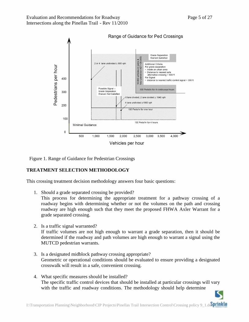
Additional guidance – for grade separated crossings - is provided in a 1984 FHWA report5. In this
report, Axler created warrants for FHWA addressing the provision of grade separated crossings.
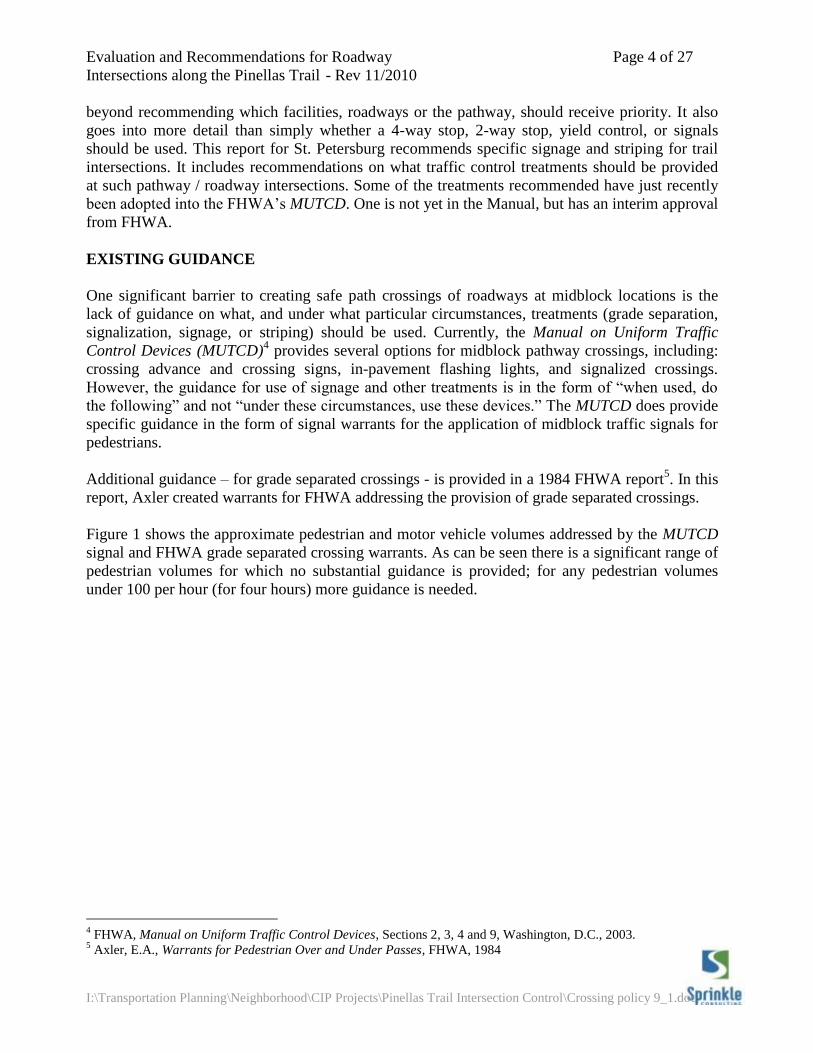
Figure 1 shows the approximate pedestrian and motor vehicle volumes addressed by the MUTCD
signal and FHWA grade separated crossing warrants. As can be seen there is a significant range of
pedestrian volumes for which no substantial guidance is provided; for any pedestrian volumes
under 100 per hour (for four hours) more guidance is needed.
4 FHWA, Manual on Uniform Traffic Control Devices, Sections 2, 3, 4 and 9, Washington, D.C., 2003.
5 Axler, E.A., Warrants for Pedestrian Over and Under Passes, FHWA, 1984
Evaluation and Recommendations for Roadway Page 5 of 27
Intersections along the Pinellas Trail - Rev 11/2010
I:\Transportation Planning\Neighborhood\CIP Projects\Pinellas Trail Intersection Control\Crossing policy 9_1.doc
TREATMENT SELECTION METHODOLOGY
This crossing treatment decision methodology answers four basic questions:
1. Should a grade separated crossing be provided?
This process for determining the appropriate treatment for a pathway crossing of a
roadway begins with determining whether or not the volumes on the path and crossing
roadway are high enough such that they meet the proposed FHWA Axler Warrant for a
grade separated crossing.
2. Is a traffic signal warranted?
If traffic volumes are not high enough to warrant a grade separation, then it should be
determined if the roadway and path volumes are high enough to warrant a signal using the
MUTCD pedestrian warrants.
3. Is a designated midblock pathway crossing appropriate?
Geometric or operational conditions should be evaluated to ensure providing a designated
crosswalk will result in a safe, convenient crossing.
4. What specific measures should be installed?
The specific traffic control devices that should be installed at particular crossings will vary
with the traffic and roadway conditions. The methodology should help determine
Figure 1. Range of Guidance for Pedestrian Crossings
Evaluation and Recommendations for Roadway Page 6 of 27
Intersections along the Pinellas Trail - Rev 11/2010
I:\Transportation Planning\Neighborhood\CIP Projects\Pinellas Trail Intersection Control\Crossing policy 9_1.doc
who should be given priority at intersections and what devices, or combinations thereof,
should be installed at the intersection.
The proposed crossing methodology is discussed in the following sections.
Grade Separated Crossings
Grade separated crossings are generally seen as the most desirable way to address conflicts
between pathway and roadway users. Those provided along the Pinellas Trail are generally safe,
convenient, and comfortable for all users.
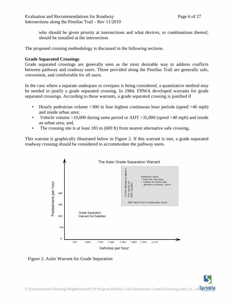
In the case where a separate underpass or overpass is being considered, a quantitative method may
be needed to justify a grade separated crossing. In 1984, FHWA developed warrants for grade
separated crossings. According to these warrants, a grade separated crossing is justified if
• Hourly pedestrian volume >300 in four highest continuous hour periods (speed >40 mph)
and inside urban area;
• Vehicle volume >10,000 during same period or ADT >35,000 (speed >40 mph) and inside
an urban area; and,
• The crossing site is at least 183 m (600 ft) from nearest alternative safe crossing.
This warrant is graphically illustrated below in Figure 2. If this warrant is met, a grade separated
roadway crossing should be considered to accommodate the pathway users.
Figure 2. Axler Warrant for Grade Separation
Evaluation and Recommendations for Roadway Page 7 of 27
Intersections along the Pinellas Trail - Rev 11/2010
I:\Transportation Planning\Neighborhood\CIP Projects\Pinellas Trail Intersection Control\Crossing policy 9_1.doc
Signalized Crossings
The MUTCD provides warrants for the installation of traffic signals.6 Any of the warrants
described in the MUTCD can be used for pathway / roadway intersections. When using the
vehicular warrants, however, only bicyclists should be considered as volume on the path.
Alternatively, bicyclists can be counted as pedestrians for the application of the Pedestrian
Volumes warrant.
The most common signal warrant used for the installation of traffic signals at pathway crossings is
Warrant 4, Pedestrian Volumes. This warrant states that a signal for a midblock or intersection
crossing can be considered if an engineering study finds both of the following:
The pedestrian volume crossing the major street at an intersection or midblock location
during an average day is 100 or more for each of any 4 hours or 190 or more during any 1
hour; and
There are fewer than 60 gaps per hour in the traffic stream of adequate length to allow
pedestrians to cross during the same period when the pedestrian volume criterion is
satisfied. Where there is a divided street having a median of sufficient width for
pedestrians to wait, the requirement applies separately to each direction of vehicular traffic.
The MUTCD goes on to say that the Pedestrian Volume signal warrant shall not be applied at
locations where the distance to the nearest traffic control signal along the major street is less than
300 ft, unless the proposed traffic control signal will not restrict the progressive movement of
[roadway] traffic.
This warrant requires actual roadway traffic volume and pedestrian (or bicycle) counts for the
pathway and motor vehicle counts on the roadway. Additionally, to satisfy the pedestrian warrant
the number of adequate gaps in the roadway traffic stream must be counted. Unfortunately,
determining the demand for a potential midblock pathway crossing location is not something that
can be done by counting the existing number of individuals crossing the roadway. Some method
using a surrogate site, or perhaps latent demand, must be employed to estimate the number of
users that would cross at a new signalized crossing.
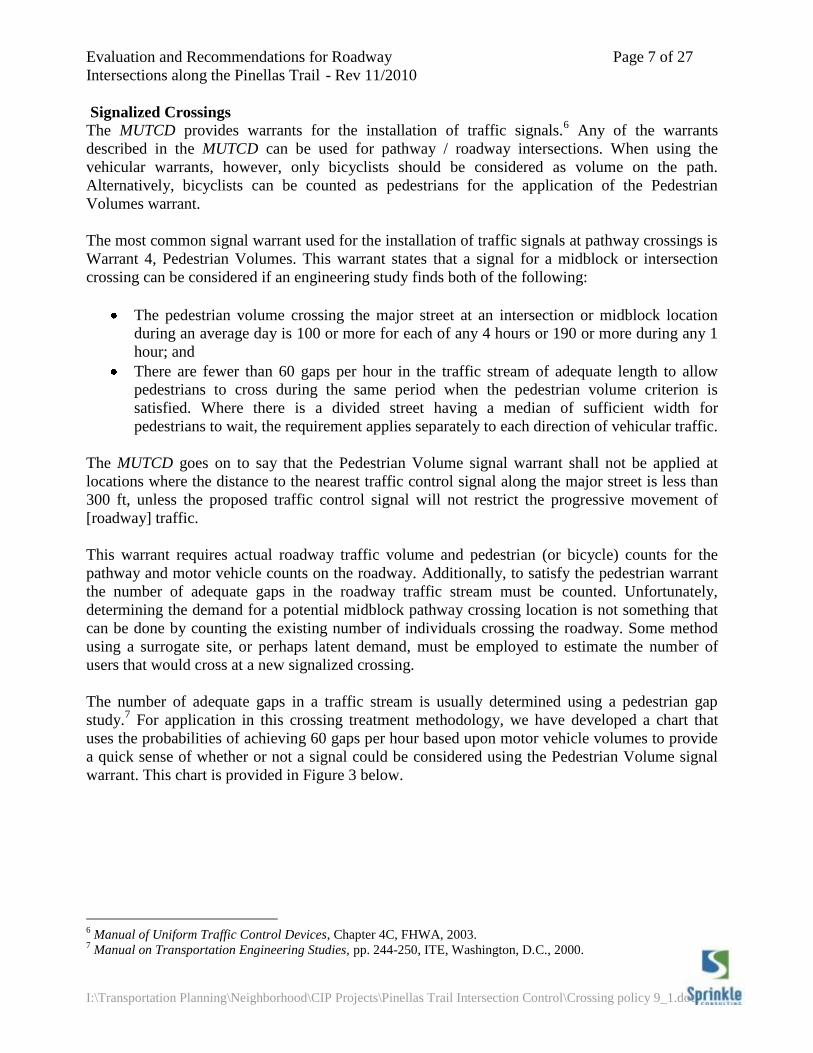
The number of adequate gaps in a traffic stream is usually determined using a pedestrian gap
study.7 For application in this crossing treatment methodology, we have developed a chart that
uses the probabilities of achieving 60 gaps per hour based upon motor vehicle volumes to provide
a quick sense of whether or not a signal could be considered using the Pedestrian Volume signal
warrant. This chart is provided in Figure 3 below.
6 Manual of Uniform Traffic Control Devices, Chapter 4C, FHWA, 2003.
7 Manual on Transportation Engineering Studies, pp. 244-250, ITE, Washington, D.C., 2000.
Evaluation and Recommendations for Roadway Page 8 of 27
Intersections along the Pinellas Trail - Rev 11/2010
I:\Transportation Planning\Neighborhood\CIP Projects\Pinellas Trail Intersection Control\Crossing policy 9_1.doc
Unsignalized Crossings
When a pathway / roadway intersection does not meet the warrants for a signal, unsignalized
treatments should be considered. The following sections address three aspects concerning
designating and designing unsignalized midblock path roadway crossings. First, we discuss
geometric constraints which may make realigning the trail intersection to a near intersection a
more appropriate crossing treatment than a designated midblock crossing. The next section
discusses how to assign priority at a midblock path / roadway intersection. Then we provide
guidance on the selection of traffic control devices for path / roadway intersections.
Roadway geometric constraints
Roadway geometrics are an important factor because they dictate if the midblock pathway
crossing can be designed safely. Two primary factors need to be considered: sight distance and
proximity to intersections.
The sight distances available to motorists and path users must be adequate to allow for a safe
crossing. Sight distance provided for motorists should be at least equal to the stopping sight
distance for the design speed of the roadway. For these values refer to A Policy on the Geometric
Design of Streets and Highways.8 While motorists are required to yield the right of way to
pedestrians, pedestrians are more comfortable crossing the street when they have adequate sight
8 AASHTO, A Policy on the Geometric Design of Streets and Highways, AASHTO, Washington, D.C., 2005.
Figure 3. Pedestrian Volume Signal Warrant
Evaluation and Recommendations for Roadway Page 9 of 27
Intersections along the Pinellas Trail - Rev 11/2010
I:\Transportation Planning\Neighborhood\CIP Projects\Pinellas Trail Intersection Control\Crossing policy 9_1.doc
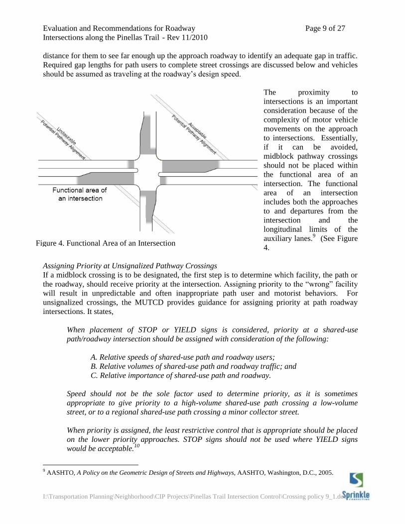
Figure 4. Functional Area of an Intersection
distance for them to see far enough up the approach roadway to identify an adequate gap in traffic.
Required gap lengths for path users to complete street crossings are discussed below and vehicles
should be assumed as traveling at the roadway’s design speed.
The proximity to
intersections is an important
consideration because of the
complexity of motor vehicle
movements on the approach
to intersections. Essentially,
if it can be avoided,
midblock pathway crossings
should not be placed within
the functional area of an
intersection. The functional
area of an intersection
includes both the approaches
to and departures from the
intersection and the
longitudinal limits of the
auxiliary lanes.9 (See Figure
4.
Assigning Priority at Unsignalized Pathway Crossings
If a midblock crossing is to be designated, the first step is to determine which facility, the path or
the roadway, should receive priority at the intersection. Assigning priority to the “wrong” facility
will result in unpredictable and often inappropriate path user and motorist behaviors. For
unsignalized crossings, the MUTCD provides guidance for assigning priority at path roadway
intersections. It states,
When placement of STOP or YIELD signs is considered, priority at a shared-use
path/roadway intersection should be assigned with consideration of the following:
A. Relative speeds of shared-use path and roadway users;
B. Relative volumes of shared-use path and roadway traffic; and
C. Relative importance of shared-use path and roadway.
Speed should not be the sole factor used to determine priority, as it is sometimes
appropriate to give priority to a high-volume shared-use path crossing a low-volume
street, or to a regional shared-use path crossing a minor collector street.
When priority is assigned, the least restrictive control that is appropriate should be placed
on the lower priority approaches. STOP signs should not be used where YIELD signs
would be acceptable.10
9 AASHTO, A Policy on the Geometric Design of Streets and Highways, AASHTO, Washington, D.C., 2005.
Evaluation and Recommendations for Roadway Page 10 of 27
Intersections along the Pinellas Trail - Rev 11/2010
I:\Transportation Planning\Neighborhood\CIP Projects\Pinellas Trail Intersection Control\Crossing policy 9_1.doc
It should not be a forgone conclusion that the roadway speeds will be higher than the pathway’s.
On sidepath type facilities (where the path is within the right of way of a parallel street) the
motorists on the roadways intersecting the path frequently are reducing speeds to negotiate the
adjacent roadway / side street intersection. Additionally, consideration given to the roadway
having higher speeds might be offset by the volume of the pathway being much higher than that of
the roadway. A local roadway might also be considered a lower priority than a regional pathway
(such as the Pinellas Trail). The Pinellas Trail (existing and proposed extension) has a higher
volume than the local roadways it crosses. However, on future extensions, or on other trails, it
may be a factor to consider when assigning priority.
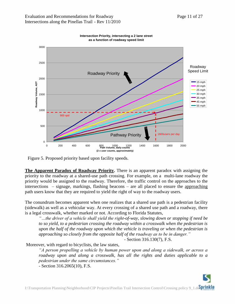
For assigning priority at pathway intersections with two-lane roadways, we propose comparing the
volumes and speeds of the Pinellas Trail and intersecting roadways to determine which facility
should get priority. Figure 5 below shows how this would be applied. Essentially the slope of
each line has been adjusted to reflect the proportionate speeds of the intersecting facilities (a 20
mph design speed was used for the Pinellas Trail).
Using this assignment method and counts provided by the City and trail counts provided by the
County11
, we applied Figure 5 to identify which facilities would receive priority at two-lane
roadway intersections. For instance, based upon Pinellas County Pinellas Trail user counts there
are about 1,600 users per day on the Pinellas Trail. Therefore, if the trail intersects a roadway with
a daily traffic of 900 vpd, and a speed limit of 30 mph, the trail would receive priority over the
roadway. If however, the roadway had a speed limit of 45 mph roadway, the roadway would
receive the priority.
On four-lane roadways, the priority is automatically assigned to the roadway. This was done for a
number of reasons. Multi-lane roadways are typically higher priority roadways; speeds are
typically higher on multilane roadways; and with multiple lanes in each direction, there is a
potential for multiple threat crashes.
10
FHWA, Manual on Uniform Traffic Control Devices, pg. 9B-2, FHWA, Washington, D.C., 2003. 11
An approximate average daily volume of 1600 users per day was used for the Pinellas Trail.
Evaluation and Recommendations for Roadway Page 11 of 27
Intersections along the Pinellas Trail - Rev 11/2010
I:\Transportation Planning\Neighborhood\CIP Projects\Pinellas Trail Intersection Control\Crossing policy 9_1.doc
Intersection Priority, intersecting a 2 lane street
as a function of roadway speed limit
0
500
1000
1500
2000
2500
3000
0 200 400 600 800 1000 1200 1400 1600 1800 2000Path Volume, daily counts
(2 x user counts, approximately)
Ro
ad
wa
y V
olu
me
, A
DT 15 mph
20 mph
25 mph
30 mph
35 mph
45 mph
55 mph
Roadway Priority
Pathway Priority
900 vpd
1600users per day
The Apparent Paradox of Roadway Priority. There is an apparent paradox with assigning the
priority to the roadway at a shared-use path crossing. For example, on a multi-lane roadway the
priority would be assigned to the roadway. Therefore, the traffic control on the approaches to the
intersections – signage, markings, flashing beacons – are all placed to ensure the approaching
path users know that they are required to yield the right of way to the roadway users.
The conundrum becomes apparent when one realizes that a shared use path is a pedestrian facility
(sidewalk) as well as a vehicular way. At every crossing of a shared use path and a roadway, there
is a legal crosswalk, whether marked or not. According to Florida Statutes,
“…the driver of a vehicle shall yield the right-of-way, slowing down or stopping if need be
to so yield, to a pedestrian crossing the roadway within a crosswalk when the pedestrian is
upon the half of the roadway upon which the vehicle is traveling or when the pedestrian is
approaching so closely from the opposite half of the roadway as to be in danger.”
- Section 316.130(7), F.S.
Moreover, with regard to bicyclists, the law states,
“A person propelling a vehicle by human power upon and along a sidewalk, or across a
roadway upon and along a crosswalk, has all the rights and duties applicable to a
pedestrian under the same circumstances.”
- Section 316.2065(10), F.S.
Figure 5. Proposed priority based upon facility speeds.
Roadway Speed Limit
Evaluation and Recommendations for Roadway Page 12 of 27
Intersections along the Pinellas Trail - Rev 11/2010
I:\Transportation Planning\Neighborhood\CIP Projects\Pinellas Trail Intersection Control\Crossing policy 9_1.doc
Consequently, when priority is assigned to the roadway, we are apparently requiring pathway
users to yield to traffic that is required by law to yield to pathway users. In actuality, when we
assign priority at an intersection we are requiring traffic approaching the intersection to yield to
traffic on the other approaches. However, this assignment of priority does not exempt path users or
motorists from their obligation to yield to users already within the intersection.12
This conundrum
is not merely academic – it underscores importance of careful design and selection of traffic
control at path roadway intersections. Improper or incomplete design, and /or maintenance of
pathway / roadway intersections have and will continue to contribute to crashes, injuries and
deaths.
Driveways. Shared use path crossings of driveways are a special case path /roadway intersection.
How they are addressed is dependent upon the location of path with regard to parallel roadways.
Where shared use paths that are along independent alignments (not adjacent to a roadway) cross
driveways, priority should be assigned just as with any other path / roadway intersection. The
relative speeds and volumes should be considered and priority set as described above.
If the path is parallel and relatively close to an adjacent roadway, there are two options for
assigning priority. Ideally, at unsignalized crossings, the path would be realigned to cross the
driveway far enough away from the roadway paralleling the path to act as an independent
intersection. If this can be done, then priority should be determined using the relative speeds and
volumes of the driveway and the path. If, however, the path must remain close to the parallel
roadway, then the path should be given the same priority over entering driveways as the parallel
roadway.
Appropriate Traffic Control for the Crossing
Once the priority has been assigned at the intersection, appropriate traffic control treatments must
be selected. The traffic control used at pathway / roadway intersections must accomplish several
objectives:
1. Make pathway users and roadway users aware of the crossing conflict;
2. Make users understand their obligations with regard to yielding on the approach to the
crossing; and,
3. Clarify the motorists’ obligations to path users within the crosswalk itself.
The method for determining traffic control for pathway / roadway intersections described below
addresses these three objectives.
The width of the roadway being crossed by the trail users and the motor vehicle volumes are the
determining factors for making this decision. This methodology uses these factors in combination
to stratify roadways by volume for application of different traffic control device packages.
For these guidelines, roadways are stratified into low-, medium-, and high-volume. The threshold
volume for low- to medium-volume was determined using the amount of time a pedestrian can
expect to wait for an adequate gap in traffic to cross the street. The medium- to high-volume
threshold is based upon the midblock crossing study previously referenced.
12
Section 316.121(1), F.S. and Section 316.130(8)
Evaluation and Recommendations for Roadway Page 13 of 27
Intersections along the Pinellas Trail - Rev 11/2010
I:\Transportation Planning\Neighborhood\CIP Projects\Pinellas Trail Intersection Control\Crossing policy 9_1.doc
Low- to Medium-Volume Threshold. Low volume roadways were those on which a path user
could expect to obtain an adequate gap to cross the street safely within 15 seconds of arriving at
the pathway / roadway intersection. The 85 percentile delay time was used to determine the upper
threshold for this roadway volume range; that is, 85 percent of the path users would be able to
begin crossing in a safe gap within 15 seconds of arriving at the intersection.
To calculate the required gaps, several assumptions about the users and the roadways were
required. The lengths of adequate gaps were calculated assuming 12-foot lanes, a startup time of 2
seconds, and a crossing speed of 3.5 ft/sec. Table 1 below shows the gap lengths for different
numbers of lanes. For roadways with a minimum 6-foot median, a pedestrian can select an
adequate gap to cross one direction of traffic, cross to the median, wait for an adequate gap to
cross the opposite direction of traffic, and cross to the far side of the roadway. For roadways
without a minimum 6-foot median, the pathway user must select a gap that is adequate to cross the
entire roadway.
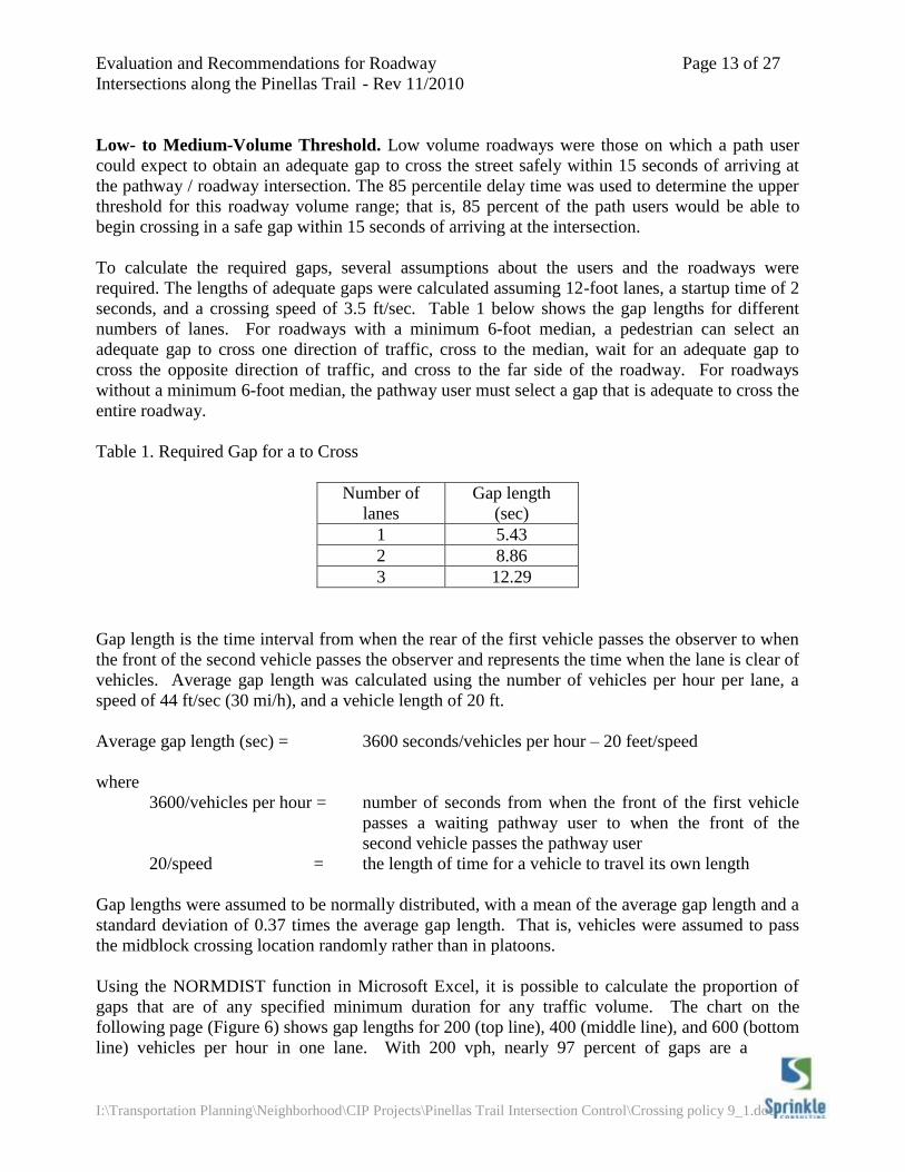
Table 1. Required Gap for a to Cross
Number of
lanes
Gap length
(sec)
1 5.43
2 8.86
3 12.29
Gap length is the time interval from when the rear of the first vehicle passes the observer to when
the front of the second vehicle passes the observer and represents the time when the lane is clear of
vehicles. Average gap length was calculated using the number of vehicles per hour per lane, a
speed of 44 ft/sec (30 mi/h), and a vehicle length of 20 ft.
Average gap length (sec) = 3600 seconds/vehicles per hour – 20 feet/speed
where
3600/vehicles per hour = number of seconds from when the front of the first vehicle
passes a waiting pathway user to when the front of the
second vehicle passes the pathway user
20/speed = the length of time for a vehicle to travel its own length
Gap lengths were assumed to be normally distributed, with a mean of the average gap length and a
standard deviation of 0.37 times the average gap length. That is, vehicles were assumed to pass
the midblock crossing location randomly rather than in platoons.
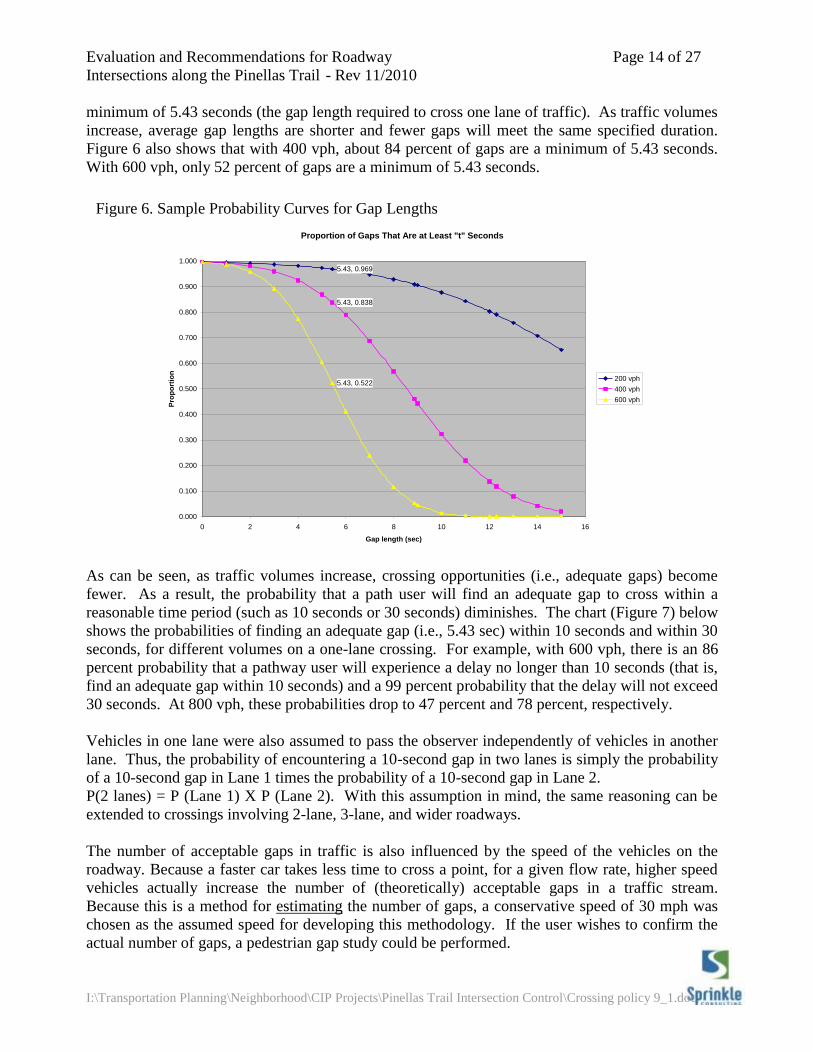
Using the NORMDIST function in Microsoft Excel, it is possible to calculate the proportion of
gaps that are of any specified minimum duration for any traffic volume. The chart on the
following page (Figure 6) shows gap lengths for 200 (top line), 400 (middle line), and 600 (bottom
line) vehicles per hour in one lane. With 200 vph, nearly 97 percent of gaps are a
Evaluation and Recommendations for Roadway Page 14 of 27
Intersections along the Pinellas Trail - Rev 11/2010
I:\Transportation Planning\Neighborhood\CIP Projects\Pinellas Trail Intersection Control\Crossing policy 9_1.doc
minimum of 5.43 seconds (the gap length required to cross one lane of traffic). As traffic volumes
increase, average gap lengths are shorter and fewer gaps will meet the same specified duration.
Figure 6 also shows that with 400 vph, about 84 percent of gaps are a minimum of 5.43 seconds.
With 600 vph, only 52 percent of gaps are a minimum of 5.43 seconds.
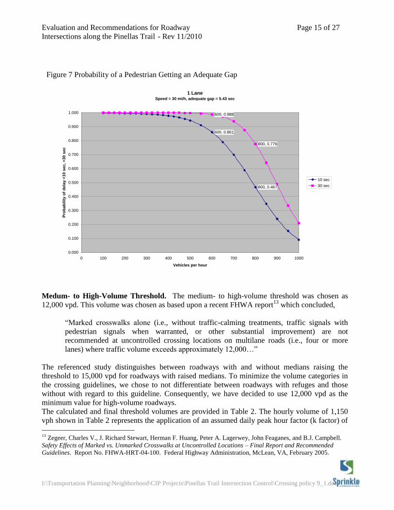
As can be seen, as traffic volumes increase, crossing opportunities (i.e., adequate gaps) become
fewer. As a result, the probability that a path user will find an adequate gap to cross within a
reasonable time period (such as 10 seconds or 30 seconds) diminishes. The chart (Figure 7) below
shows the probabilities of finding an adequate gap (i.e., 5.43 sec) within 10 seconds and within 30
seconds, for different volumes on a one-lane crossing. For example, with 600 vph, there is an 86
percent probability that a pathway user will experience a delay no longer than 10 seconds (that is,
find an adequate gap within 10 seconds) and a 99 percent probability that the delay will not exceed
30 seconds. At 800 vph, these probabilities drop to 47 percent and 78 percent, respectively.
Vehicles in one lane were also assumed to pass the observer independently of vehicles in another
lane. Thus, the probability of encountering a 10-second gap in two lanes is simply the probability
of a 10-second gap in Lane 1 times the probability of a 10-second gap in Lane 2.
P(2 lanes) = P (Lane 1) X P (Lane 2). With this assumption in mind, the same reasoning can be
extended to crossings involving 2-lane, 3-lane, and wider roadways.
The number of acceptable gaps in traffic is also influenced by the speed of the vehicles on the
roadway. Because a faster car takes less time to cross a point, for a given flow rate, higher speed
vehicles actually increase the number of (theoretically) acceptable gaps in a traffic stream.
Because this is a method for estimating the number of gaps, a conservative speed of 30 mph was
chosen as the assumed speed for developing this methodology. If the user wishes to confirm the
actual number of gaps, a pedestrian gap study could be performed.
Figure 6. Sample Probability Curves for Gap Lengths
Proportion of Gaps That Are at Least "t" Seconds
5.43, 0.969
5.43, 0.838
5.43, 0.522
0.000
0.100
0.200
0.300
0.400
0.500
0.600
0.700
0.800
0.900
1.000
0 2 4 6 8 10 12 14 16
Gap length (sec)
Pro
po
rtio
n
200 vph
400 vph
600 vph
Evaluation and Recommendations for Roadway Page 15 of 27
Intersections along the Pinellas Trail - Rev 11/2010
I:\Transportation Planning\Neighborhood\CIP Projects\Pinellas Trail Intersection Control\Crossing policy 9_1.doc
Medum- to High-Volume Threshold. The medium- to high-volume threshold was chosen as
12,000 vpd. This volume was chosen as based upon a recent FHWA report13
which concluded,
“Marked crosswalks alone (i.e., without traffic-calming treatments, traffic signals with
pedestrian signals when warranted, or other substantial improvement) are not
recommended at uncontrolled crossing locations on multilane roads (i.e., four or more
lanes) where traffic volume exceeds approximately 12,000…”
The referenced study distinguishes between roadways with and without medians raising the
threshold to 15,000 vpd for roadways with raised medians. To minimize the volume categories in
the crossing guidelines, we chose to not differentiate between roadways with refuges and those
without with regard to this guideline. Consequently, we have decided to use 12,000 vpd as the
minimum value for high-volume roadways.
The calculated and final threshold volumes are provided in Table 2. The hourly volume of 1,150
vph shown in Table 2 represents the application of an assumed daily peak hour factor (k factor) of
13
Zegeer, Charles V., J. Richard Stewart, Herman F. Huang, Peter A. Lagerwey, John Feaganes, and B.J. Campbell.
Safety Effects of Marked vs. Unmarked Crosswalks at Uncontrolled Locations – Final Report and Recommended
Guidelines. Report No. FHWA-HRT-04-100. Federal Highway Administration, McLean, VA, February 2005.
Figure 7 Probability of a Pedestrian Getting an Adequate Gap
1 LaneSpeed = 30 mi/h, adequate gap = 5.43 sec
800, 0.467
600, 0.861
800, 0.776
600, 0.988
0.000
0.100
0.200
0.300
0.400
0.500
0.600
0.700
0.800
0.900
1.000
0 100 200 300 400 500 600 700 800 900 1000
Vehicles per hour
Pro
bab
ilit
y o
f d
ela
y <
10 s
ec, <
30 s
ec
10 sec
30 sec
Evaluation and Recommendations for Roadway Page 16 of 27
Intersections along the Pinellas Trail - Rev 11/2010
I:\Transportation Planning\Neighborhood\CIP Projects\Pinellas Trail Intersection Control\Crossing policy 9_1.doc
0.097. These thresholds pertain to an undivided roadway or a divided roadway with less than 6 ft
of raised median. For a divided roadway with a minimum 6-foot raised median, these thresholds
pertain to each direction of traffic. The Guidelines Total Traffic Volumes column of Table 2
contains generalized values based upon the calculated volumes.
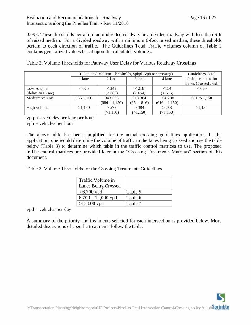
Table 2. Volume Thresholds for Pathway User Delay for Various Roadway Crossings
Calculated Volume Thresholds, vphpl (vph for crossing) Guidelines Total
Traffic Volume for
Lanes Crossed , vph 1 lane 2 lane 3 lane 4 lane
Low volume
(delay <=15 sec)
< 665 < 343
(< 686)
< 218
(< 654)
<154
(< 616)
< 650
Medium volume
665-1,150
343-575
(686 – 1,150)
218-384
(654 - 816)
154-288
(616 – 1,150)
651 to 1,150
High-volume
>1,150
> 575
(>1,150)
> 384
(>1,150)
> 288
(>1,150)
>1,150
vplph = vehicles per lane per hour
vph = vehicles per hour
The above table has been simplified for the actual crossing guidelines application. In the
application, one would determine the volume of traffic in the lanes being crossed and use the table
below (Table 3) to determine which table in the traffic control matrices to use. The proposed
traffic control matrices are provided later in the “Crossing Treatments Matrices” section of this
document.
Table 3. Volume Thresholds for the Crossing Treatments Guidelines
Traffic Volume in
Lanes Being Crossed
< 6,700 vpd Table 5
6,700 – 12,000 vpd Table 6
>12,000 vpd Table 7
vpd = vehicles per day
A summary of the priority and treatments selected for each intersection is provided below. More
detailed discussions of specific treatments follow the table.
Evaluation and Recommendations for Roadway Page 17 of 27
Intersections along the Pinellas Trail - Rev 11/2010
I:\Transportation Planning\Neighborhood\CIP Projects\Pinellas Trail Intersection Control\Crossing policy 9_1.doc
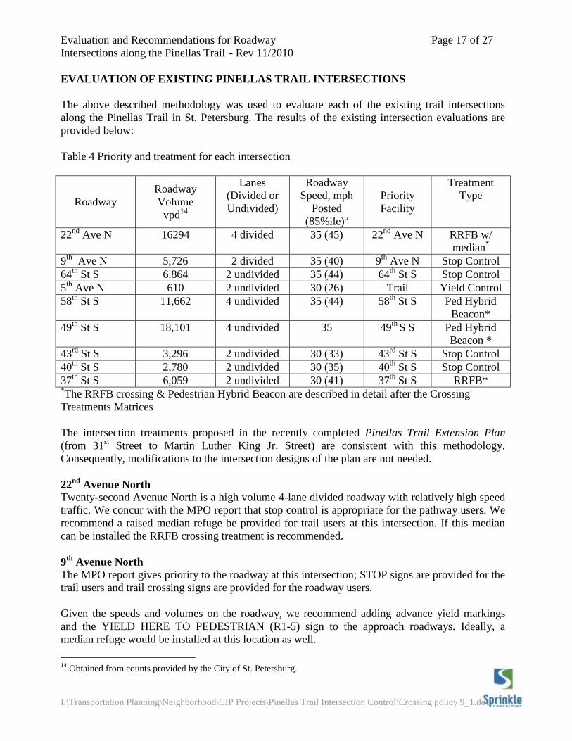
EVALUATION OF EXISTING PINELLAS TRAIL INTERSECTIONS
The above described methodology was used to evaluate each of the existing trail intersections
along the Pinellas Trail in St. Petersburg. The results of the existing intersection evaluations are
provided below:
Table 4 Priority and treatment for each intersection
Roadway
Roadway
Volume
vpd14
Lanes
(Divided or
Undivided)
Roadway
Speed, mph
Posted
(85%ile)5
Priority
Facility
Treatment
Type
22nd
Ave N 16294 4 divided 35 (45) 22nd
Ave N RRFB w/
median*
9th
Ave N 5,726 2 divided 35 (40) 9th
Ave N Stop Control
64th
St S 6.864 2 undivided 35 (44) 64th
St S Stop Control
5th
Ave N 610 2 undivided 30 (26) Trail Yield Control
58th
St S 11,662 4 undivided 35 (44) 58th
St S Ped Hybrid
Beacon*
49th
St S 18,101 4 undivided 35 49th
S S Ped Hybrid
Beacon *
43rd
St S 3,296 2 undivided 30 (33) 43rd
St S Stop Control
40th
St S 2,780 2 undivided 30 (35) 40th
St S Stop Control
37th
St S 6,059 2 undivided 30 (41) 37th
St S RRFB* *The RRFB crossing & Pedestrian Hybrid Beacon are described in detail after the Crossing
Treatments Matrices
The intersection treatments proposed in the recently completed Pinellas Trail Extension Plan
(from 31st Street to Martin Luther King Jr. Street) are consistent with this methodology.
Consequently, modifications to the intersection designs of the plan are not needed.
22nd
Avenue North
Twenty-second Avenue North is a high volume 4-lane divided roadway with relatively high speed
traffic. We concur with the MPO report that stop control is appropriate for the pathway users. We
recommend a raised median refuge be provided for trail users at this intersection. If this median
can be installed the RRFB crossing treatment is recommended.
9th
Avenue North
The MPO report gives priority to the roadway at this intersection; STOP signs are provided for the
trail users and trail crossing signs are provided for the roadway users.
Given the speeds and volumes on the roadway, we recommend adding advance yield markings
and the YIELD HERE TO PEDESTRIAN (R1-5) sign to the approach roadways. Ideally, a
median refuge would be installed at this location as well.
14
Obtained from counts provided by the City of St. Petersburg.
Evaluation and Recommendations for Roadway Page 18 of 27
Intersections along the Pinellas Trail - Rev 11/2010
I:\Transportation Planning\Neighborhood\CIP Projects\Pinellas Trail Intersection Control\Crossing policy 9_1.doc
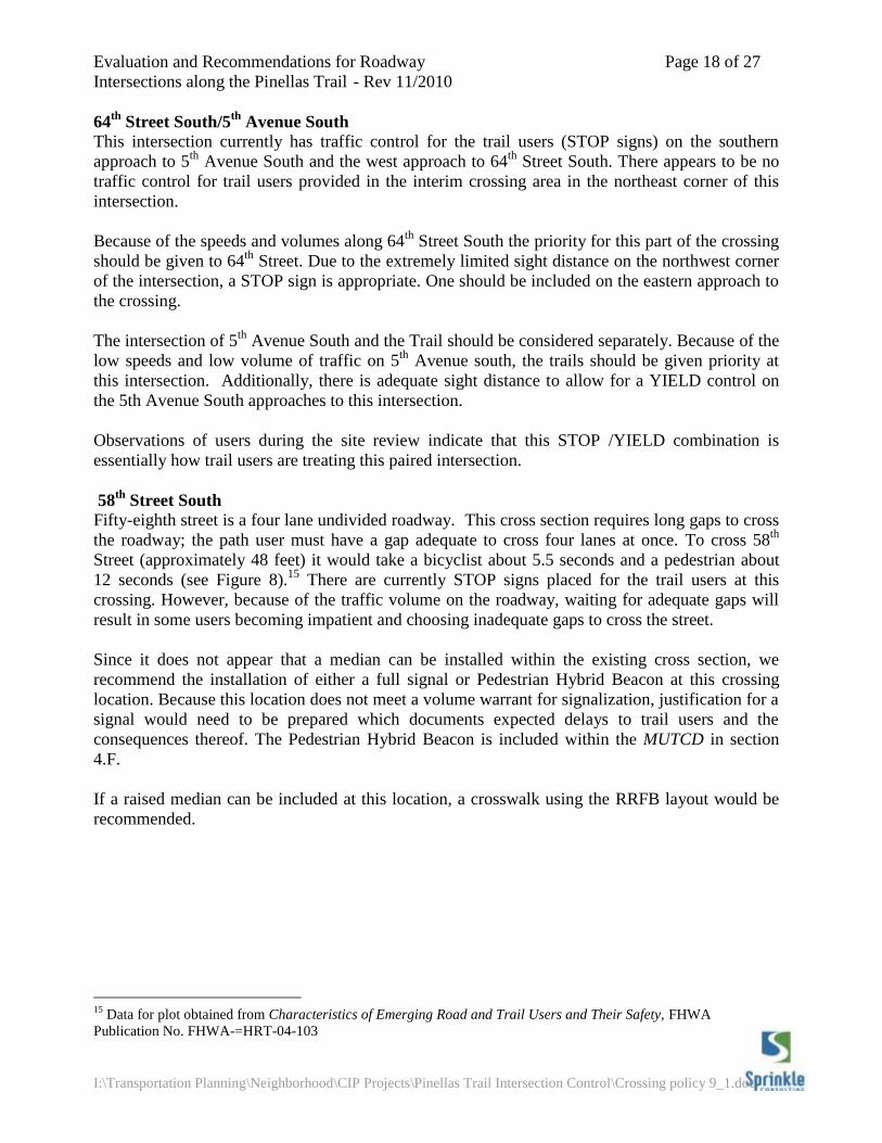
64th
Street South/5th
Avenue South
This intersection currently has traffic control for the trail users (STOP signs) on the southern
approach to 5th
Avenue South and the west approach to 64th
Street South. There appears to be no
traffic control for trail users provided in the interim crossing area in the northeast corner of this
intersection.
Because of the speeds and volumes along 64th
Street South the priority for this part of the crossing
should be given to 64th
Street. Due to the extremely limited sight distance on the northwest corner
of the intersection, a STOP sign is appropriate. One should be included on the eastern approach to
the crossing.
The intersection of 5th
Avenue South and the Trail should be considered separately. Because of the
low speeds and low volume of traffic on 5th
Avenue south, the trails should be given priority at
this intersection. Additionally, there is adequate sight distance to allow for a YIELD control on
the 5th Avenue South approaches to this intersection.
Observations of users during the site review indicate that this STOP /YIELD combination is
essentially how trail users are treating this paired intersection.
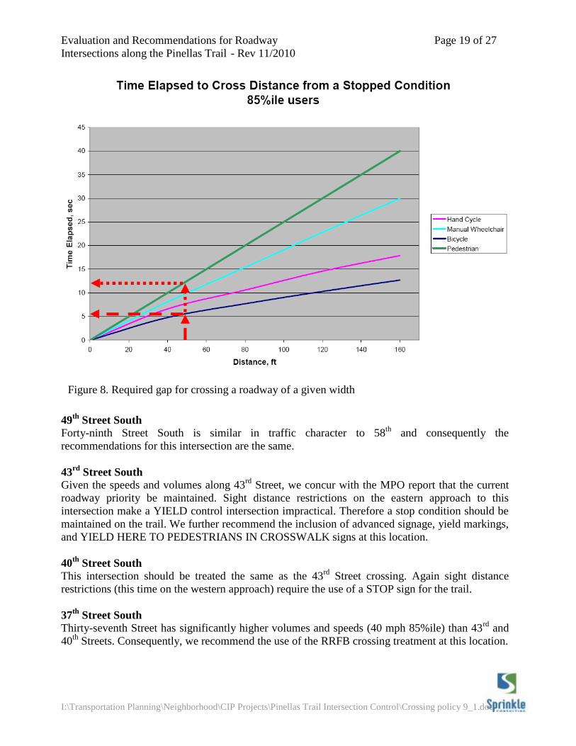
58th
Street South
Fifty-eighth street is a four lane undivided roadway. This cross section requires long gaps to cross
the roadway; the path user must have a gap adequate to cross four lanes at once. To cross 58th
Street (approximately 48 feet) it would take a bicyclist about 5.5 seconds and a pedestrian about
12 seconds (see Figure 8).15
There are currently STOP signs placed for the trail users at this
crossing. However, because of the traffic volume on the roadway, waiting for adequate gaps will
result in some users becoming impatient and choosing inadequate gaps to cross the street.
Since it does not appear that a median can be installed within the existing cross section, we
recommend the installation of either a full signal or Pedestrian Hybrid Beacon at this crossing
location. Because this location does not meet a volume warrant for signalization, justification for a
signal would need to be prepared which documents expected delays to trail users and the
consequences thereof. The Pedestrian Hybrid Beacon is included within the MUTCD in section
4.F.
If a raised median can be included at this location, a crosswalk using the RRFB layout would be
recommended.
15
Data for plot obtained from Characteristics of Emerging Road and Trail Users and Their Safety, FHWA
Publication No. FHWA-=HRT-04-103
Evaluation and Recommendations for Roadway Page 19 of 27
Intersections along the Pinellas Trail - Rev 11/2010
I:\Transportation Planning\Neighborhood\CIP Projects\Pinellas Trail Intersection Control\Crossing policy 9_1.doc
49
th Street South
Forty-ninth Street South is similar in traffic character to 58th
and consequently the
recommendations for this intersection are the same.
43rd
Street South
Given the speeds and volumes along 43rd
Street, we concur with the MPO report that the current
roadway priority be maintained. Sight distance restrictions on the eastern approach to this
intersection make a YIELD control intersection impractical. Therefore a stop condition should be
maintained on the trail. We further recommend the inclusion of advanced signage, yield markings,
and YIELD HERE TO PEDESTRIANS IN CROSSWALK signs at this location.
40th
Street South
This intersection should be treated the same as the 43rd
Street crossing. Again sight distance
restrictions (this time on the western approach) require the use of a STOP sign for the trail.
37th
Street South
Thirty-seventh Street has significantly higher volumes and speeds (40 mph 85%ile) than 43rd
and
40th
Streets. Consequently, we recommend the use of the RRFB crossing treatment at this location.
Figure 8. Required gap for crossing a roadway of a given width
Evaluation and Recommendations for Roadway Page 20 of 27
Intersections along the Pinellas Trail - Rev 11/2010
I:\Transportation Planning\Neighborhood\CIP Projects\Pinellas Trail Intersection Control\Crossing policy 9_1.doc
CROSSING TREATMENTS MATRICES
The matrices on the following pages present packages of traffic control devices recommended for
specific roadway conditions. While providing guidance, there are sometimes field conditions
which make the strict adherence to any typical signing and marking scheme impractical.
Therefore, when applied at new locations, each location should be reviewed in the field to ensure
the proposed treatments are appropriate.
The matrices assume that the roadway is given priority. If the pathway is to be given priority, then
STOP or YIELD signs as appropriate should be installed on the roadway along with the applicable
pavement markings (stop lines or yield markings).
The following general notes apply to the crossing treatment matrices:
General notes for applying the Crossing Treatment Methodology Matrices
1. Each column in the table represents a package of traffic control devices recommended for the
specific crossing condition.
2. The designation of “YES” for the median assumes there is potential for installing a raised
median at the crossing location and that one will be installed. Raised medians that can be used
as ped refuges (6 feet wide or wider) will allow for less restrictive motor vehicle traffic
controls to be used in conjunction with the midblock crossings. The use of Danish offsets
(angled cuts through the median) should be considered at all crossings with raised medians.
3. On multi-lane roadways with medians on the approach, crossing signage should be placed in
the medians as well as on the side of the roadway.
4. At all new crossings, slight reverse curves of the path (or kinks) on the approaches to
intersections should be considered. These offsets are to alert path users to the upcoming
intersections and to act as path “calming” to reduce the speeds of path users through the
intersections.
5. The use of Danish offsets (angled cuts through the median) should be considered at all
crossings with raised medians for two reasons. First, the offset through the median directs the
path users’ attention toward the traffic about to be crossed. Secondly, by providing an angled
cut through the median, longer users (tandems, bicycles with trailers) may be better
accommodated in a narrower median. Cattle-gate style crossings which require two 90 degree
turns in a short distance can restrict the passage of longer users; if used they should be
carefully designed.
6. A solid yellow centerline stripe should be placed on all pathway approaches to path / road
intersections. This centerline stripe should extend 127 feet (stopping sight distance for a
bicyclist per AASHTO) back from the intersection. STOP or YIELD signs and applicable
markings (stop lines or yield markings) should be applied to the path surface.
Evaluation and Recommendations for Roadway Page 21 of 27
Intersections along the Pinellas Trail - Rev 11/2010
I:\Transportation Planning\Neighborhood\CIP Projects\Pinellas Trail Intersection Control\Crossing policy 9_1.doc
7. Bollards should be used sparingly and only if they are needed to prevent motor vehicle access.
On new paths only odd numbers of bollards should be used. This helps define a “center” of the
path and gives users a definitive reference for riding on the right. Even numbers of bollards
can cause confusion as to which side of the bollards a path user should ride. Where bollards
are used they should be striped as obstructions as described in the MUTCD16
. Striping around
central bollards, those separating path users traveling in opposite directions, should be yellow.
Supplemental bollards separating users traveling in the same direction should be white.
8. When advance yield lines are used on the approach roadways they would be used in
conjunction with solid lane lines extending back the stopping sight distance from yield lines.
This is to enable law enforcement officers to determine when a motorist fails to yield when he
could have done so.
9. On six-lane, undivided roadways, strong consideration should be given to providing a grade-
separated crossing of the roadway for peds/trail users. Until such time as this can be achieved
aggressive channelization should be used to divert peds/trail users to the nearest safe crossing.
10. This guidance assumes that lighting will be considered and provided where needed for
crossings that are used at night.
11. A Request to Experiment should be obtained from FHWA for all installations of non-standard
treatments such as the RRFB and the Pedestrian Hybrid Beacon.
12. Once the treatment types in the lookup tables are finalized, typical application drawings will
be provided in the final methodology.
16
FHWA, Manual on Uniform Traffic Control Devices, pg. 9C-03, FHWA, Washington, D.C., 2003.
DRAFT Crossing Treatments Methodology Page 22 of 27
Executive Summary
I:\Transportation Planning\Neighborhood\CIP Projects\Pinellas Trail Intersection Control\Crossing policy 9_1.doc
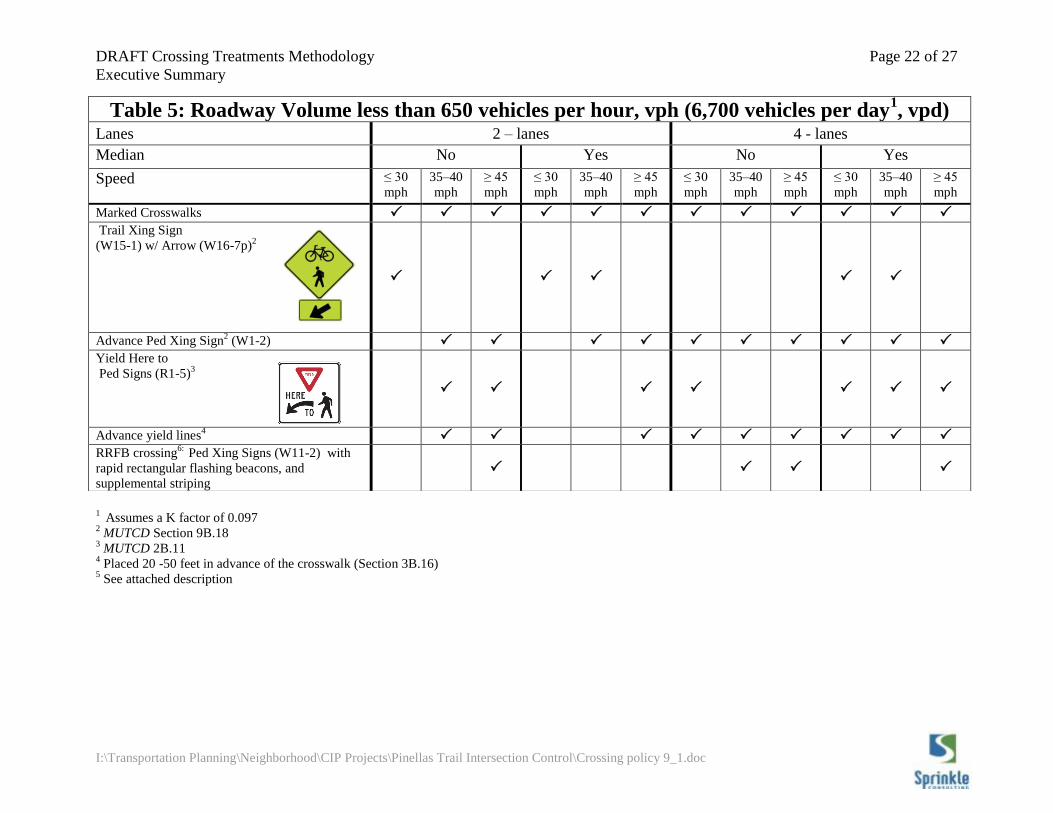
1 Assumes a K factor of 0.097
2 MUTCD Section 9B.18
3 MUTCD 2B.11
4 Placed 20 -50 feet in advance of the crosswalk (Section 3B.16)
5 See attached description
Table 5: Roadway Volume less than 650 vehicles per hour, vph (6,700 vehicles per day1, vpd)
Lanes 2 – lanes 4 - lanes
Median No Yes
No Yes
Speed ≤ 30
mph
35–40
mph
≥ 45
mph
≤ 30
mph
35–40
mph
≥ 45
mph
≤ 30
mph
35–40
mph
≥ 45
mph
≤ 30
mph
35–40
mph
≥ 45
mph
Marked Crosswalks
Trail Xing Sign
(W15-1) w/ Arrow (W16-7p)2
Advance Ped Xing Sign2 (W1-2)
Yield Here to
Ped Signs (R1-5)3
Advance yield lines4
RRFB crossing6:
Ped Xing Signs (W11-2) with
rapid rectangular flashing beacons, and
supplemental striping
DRAFT Crossing Treatments Methodology Page 23 of 27
Executive Summary
I:\Transportation Planning\Neighborhood\CIP Projects\Pinellas Trail Intersection Control\Crossing policy 9_1.doc
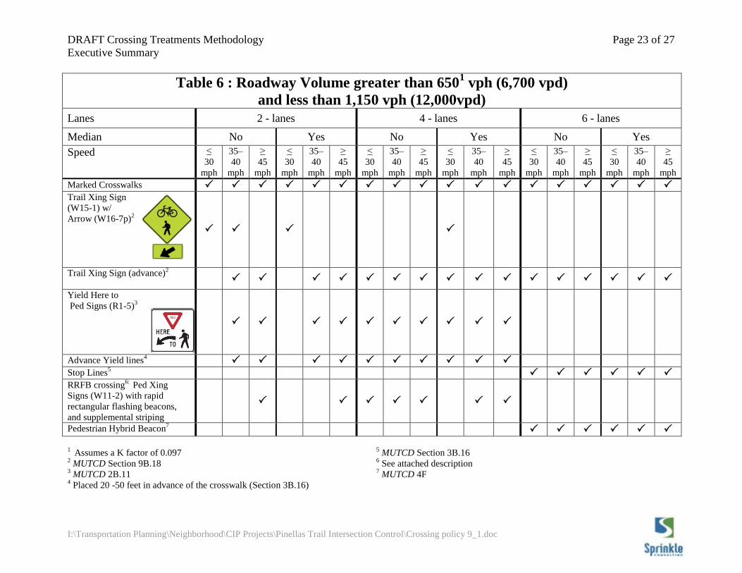
Table 6 : Roadway Volume greater than 6501 vph (6,700 vpd)
and less than 1,150 vph (12,000vpd)
Lanes 2 - lanes 4 - lanes 6 - lanes
Median No Yes No Yes No Yes
Speed ≤
30
mph
35–
40
mph
≥
45
mph
≤
30
mph
35–
40
mph
≥
45
mph
≤
30
mph
35–
40
mph
≥
45
mph
≤
30
mph
35–
40
mph
≥
45
mph
≤
30
mph
35–
40
mph
≥
45
mph
≤
30
mph
35–
40
mph
≥
45
mph
Marked Crosswalks
Trail Xing Sign
(W15-1) w/
Arrow (W16-7p)2
Trail Xing Sign (advance)2
Yield Here to
Ped Signs (R1-5)3
Advance Yield lines4
Stop Lines5
RRFB crossing6:
Ped Xing
Signs (W11-2) with rapid
rectangular flashing beacons,
and supplemental striping
Pedestrian Hybrid Beacon7
1 Assumes a K factor of 0.097
2 MUTCD Section 9B.18
3 MUTCD 2B.11
4 Placed 20 -50 feet in advance of the crosswalk (Section 3B.16)
5 MUTCD Section 3B.16
6 See attached description
7 MUTCD 4F
DRAFT Crossing Treatments Methodology Page 24 of 27
Executive Summary
I:\Transportation Planning\Neighborhood\CIP Projects\Pinellas Trail Intersection Control\Crossing policy 9_1.doc
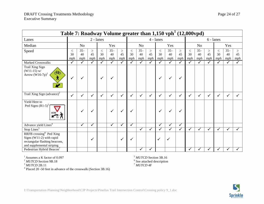
Table 7: Roadway Volume greater than 1,150 vph1 (12,000vpd)
Lanes 2 - lanes 4 - lanes 6 - lanes
Median No Yes No Yes No Yes
Speed ≤
30
mph
35–
40
mph
≥
45
mph
≤
30
mph
35–
40
mph
≥
45
mph
≤
30
mph
35–
40
mph
≥
45
mph
≤
30
mph
35–
40
mph
≥
45
mph
≤
30
mph
35–
40
mph
≥
45
mph
≤
30
mph
35–
40
mph
≥
45
mph
Marked Crosswalks
Trail Xing Sign
(W11-15) w/
Arrow (W16-7p)2
Trail Xing Sign (advance)2
Yield Here to
Ped Signs (R1-5)3
Advance yield Lines4
Stop Lines5
RRFB crossing6:
Ped Xing
Signs (W11-2) with rapid
rectangular flashing beacons,
and supplemental striping
Pedestrian Hybrid Beacon7
1 Assumes a K factor of 0.097
2 MUTCD Section 9B.18
3 MUTCD 2B.11
4 Placed 20 -50 feet in advance of the crosswalk (Section 3B.16)
5 MUTCD Section 3B.16
6 See attached description
7 MUTCD 4F
DRAFT Crossing Treatments Methodology Page 25 of 27
I:\Transportation Planning\Neighborhood\CIP Projects\Pinellas Trail Intersection
Control\Crossing policy 9_1.doc
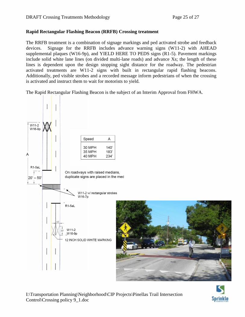
Rapid Rectangular Flashing Beacon (RRFB) Crossing treatment
The RRFB treatment is a combination of signage markings and ped activated strobe and feedback
devices. Signage for the RRFB includes advance warning signs (W11-2) with AHEAD
supplemental plaques (W16-9p), and YIELD HERE TO PEDS signs (R1-5). Pavement markings
include solid white lane lines (on divided multi-lane roads) and advance Xs; the length of these
lines is dependent upon the design stopping sight distance for the roadway. The pedestrian
activated treatments are W11-2 signs with built in rectangular rapid flashing beacons.
Additionally, ped visible strobes and a recorded message inform pedestrians of when the crossing
is activated and instruct them to wait for motorists to yield.
The Rapid Rectangular Flashing Beacon is the subject of an Interim Approval from FHWA.
DRAFT Crossing Treatments Methodology Page 26 of 27
I:\Transportation Planning\Neighborhood\CIP Projects\Pinellas Trail Intersection
Control\Crossing policy 9_1.doc
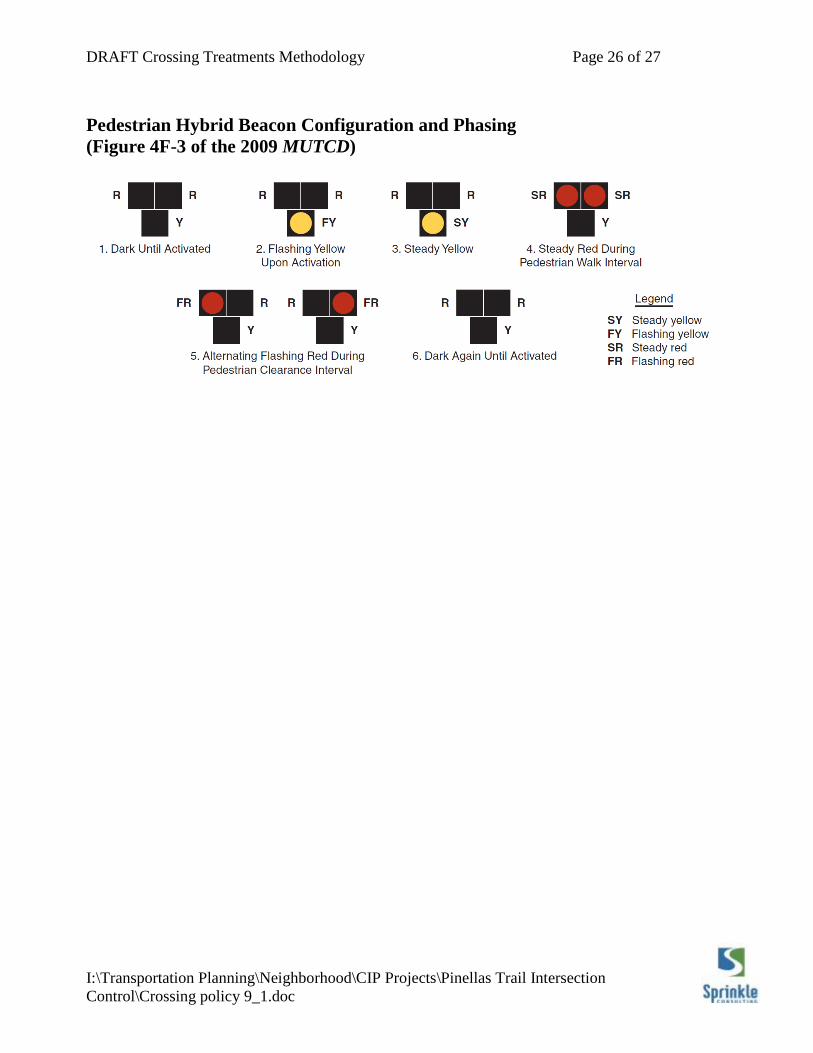
Pedestrian Hybrid Beacon Configuration and Phasing
(Figure 4F-3 of the 2009 MUTCD)
DRAFT Crossing Treatments Methodology Page 27 of 27
I:\Transportation Planning\Neighborhood\CIP Projects\Pinellas Trail Intersection
Control\Crossing policy 9_1.doc
Text from Memo of Endorsement from the Pinellas County MPO TS&MCC
To: Honorable Chairman and Members of the MPO
From: Paul Bertels, TS&MCC Chairman
Copy to: Tom Ferraro, BAC Chairman
Subject: Traffic Control at Shared Use Path/Trail Report
Date: November 20, 2007
At the meeting of November 28, 2007 the Traffic Signals Median Control Committee (TS&MCC)
discussed the Traffic Control at Shared Use Path/Trail Report endorsed by the MPO’s Bicycle
Advisory Committee (BAC) and forwarded to the TSMCC for review. The City of St. Petersburg
contracted with Sprinkle Consultants to develop a policy to provide uniform treatments of Shared
Path/Trail and roadway intersections. This was in response the MPO’s recommendations on
Pinellas Trail crossings. The Florida Department of Transportation reviewed the proposed policy
forwarded by the BAC and TS&MCC and provided comments on the report.
The TS&MCC discussed the comments submitted and recommends that the MPO forward the
comments provided by the FDOT to the City in order for them to be incorporated into the report
by the consultant.
The policies provided in the report will assist the local jurisdictions in determining the appropriate
traffic control treatment at intersections of the Pinellas Trail and other shared path/trail locations
countywide.
The TS&MCC concurs with the BAC support of the proposed policy and requests the MPO
forward FDOT’s recommended edits and changes to the City in order for the report to be finalized.
The modified report will be submitted to all local government jurisdictions to be utilized in
determining the traffic control needed at these intersections.