ping presentation
TRANSCRIPT

© Copyright Alvarion Ltd.
Simple net pinging
Date 03/06/2007
Hanan Ohana

2 Motivation
This presentation shows the flow of events for a PING request in a brand new net with static IP configured to the devices and blank ARP tables to begin with.
The PING request is sent from one computer in the IP net to another computer.
Taking in consideration: routers do not use buffers so IP packets get lost if ARP request needed.

3 Net introduction
Net containing:4 end units
2 switches
2 routers
4 Net introduction
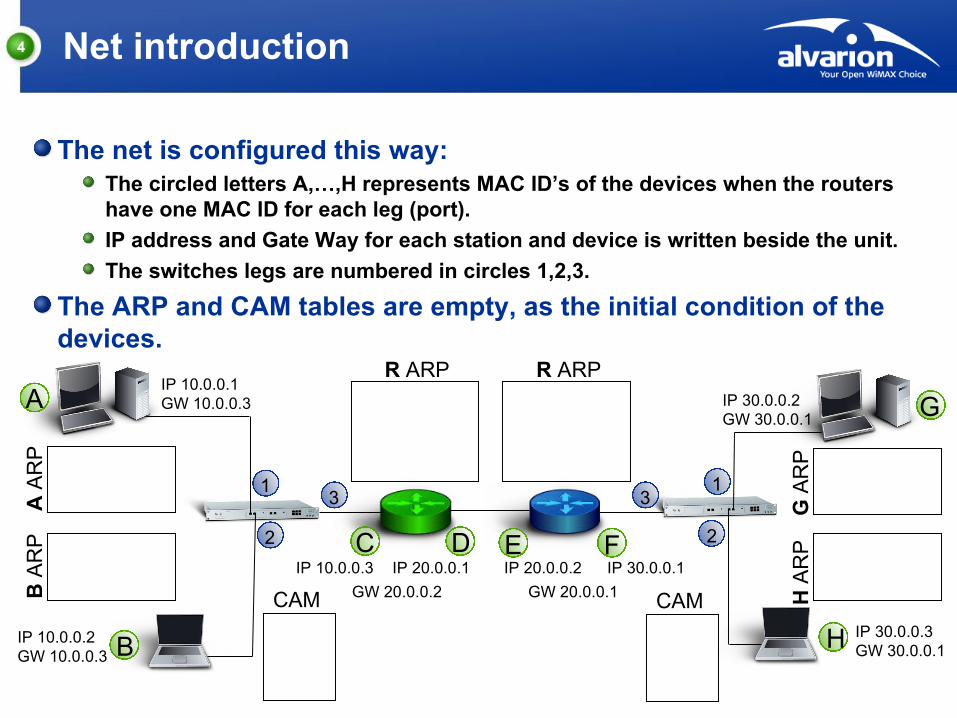
The net is configured this way:The circled letters A,…,H represents MAC ID’s of the devices when the routers have one MAC ID for each leg (port).
IP address and Gate Way for each station and device is written beside the unit.
The switches legs are numbered in circles 1,2,3.
The ARP and CAM tables are empty, as the initial condition of the devices.
1 1
2
33
2
A
B
C D E F
G
H
IP 10.0.0.1GW 10.0.0.3
IP 10.0.0.2GW 10.0.0.3
IP 10.0.0.3 IP 20.0.0.1 IP 20.0.0.2 IP 30.0.0.1
IP 30.0.0.2GW 30.0.0.1
IP 30.0.0.3GW 30.0.0.1
GW 20.0.0.2 GW 20.0.0.1
A A
RP
B A
RP
G A
RP
H A
RP
R ARP R ARP
CAM CAM

5 IP packet release algorithm
This block diagram describes the algorithm used by a network device for frame structure decision, when IP packet has to be sent.
LocalDestination
?IP
ARPTarget
MAC Known?
Send toGateway
Send todestination
Send todestination
YesNo
YesNo
Decision needed

6 PING chain of events
PING request from station A to station H:
Following PING request:
A:\>ping 30.0.0.3
1 1
2
33
2
A
B
C D E F
G
H
IP 10.0.0.1GW 10.0.0.3
IP 10.0.0.2GW 10.0.0.3
IP 10.0.0.3 IP 20.0.0.1 IP 20.0.0.2 IP 30.0.0.1
IP 30.0.0.2GW 30.0.0.1
IP 30.0.0.3GW 30.0.0.1
GW 20.0.0.2 GW 20.0.0.1
A A
RP
B A
RP
G A
RP
H A
RP
R ARP R ARP
CAM CAM

7 PING chain of events
A:\>ping 30.0.0.3
Ping request is to be released from station A, the “IP packet release algorithm” is used.
For non local destination IP and unknown target MAC, an ARP request is sent to GW, as a broadcast.
1 1
2
33
2
A
B
C D E F
G
H
IP 10.0.0.1GW 10.0.0.3
IP 10.0.0.2GW 10.0.0.3
IP 10.0.0.3 IP 20.0.0.1 IP 20.0.0.2 IP 30.0.0.1
IP 30.0.0.2GW 30.0.0.1
IP 30.0.0.3GW 30.0.0.1
GW 20.0.0.2 GW 20.0.0.1
A A
RP
B A
RP
G A
RP
H A
RP
R ARP R ARP
CAM CAM
8
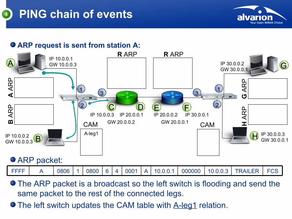
ARP packet:
The ARP packet is a broadcast so the left switch is flooding and send the same packet to the rest of the connected legs.
The left switch updates the CAM table with A-leg1 relation.
PING chain of events
ARP request is sent from station A:
FCSTRAILER10.0.0.300000010.0.0.1A000146080010806AFFFF
1 1
2
33
2
A
B
C D E F
G
H
IP 10.0.0.1GW 10.0.0.3
IP 10.0.0.2GW 10.0.0.3
IP 10.0.0.3 IP 20.0.0.1 IP 20.0.0.2 IP 30.0.0.1
IP 30.0.0.2GW 30.0.0.1
IP 30.0.0.3GW 30.0.0.1
GW 20.0.0.2 GW 20.0.0.1
A A
RP
B A
RP
G A
RP
H A
RP
R ARP R ARP
A-leg1
CAM CAM

9 PING chain of events
ARP packet arrives to station B and green router:
Station B receives the ARP packet and updates the ARP table with A-10.0.0.1 relation. Station B does not send a reply.
The green router receives the ARP packet and updates the ARP table with A-10.0.0.1 relation, sends a reply and trashes the original packet.
1 1
2
33
2
A
B
C D E F
G
H
IP 10.0.0.1GW 10.0.0.3
IP 10.0.0.2GW 10.0.0.3
IP 10.0.0.3 IP 20.0.0.1 IP 20.0.0.2 IP 30.0.0.1
IP 30.0.0.2GW 30.0.0.1
IP 30.0.0.3GW 30.0.0.1
GW 20.0.0.2 GW 20.0.0.1
A A
RP
A-10.0.0.1
B A
RP
G A
RP
H A
RP
A-10.0.0.1
R ARP R ARP
A-leg1
CAM CAM

10
1 1
2
33
2
A
B
C D E F
G
H
IP 10.0.0.1GW 10.0.0.3
IP 10.0.0.2GW 10.0.0.3
IP 10.0.0.3 IP 20.0.0.1 IP 20.0.0.2 IP 30.0.0.1
IP 30.0.0.2GW 30.0.0.1
IP 30.0.0.3GW 30.0.0.1
GW 20.0.0.2 GW 20.0.0.1
C-10.0.0.3
A A
RP
A-10.0.0.1
B A
RP
G A
RP
H A
RP
A-10.0.0.1
R ARP R ARP
A-leg1
C-leg3
CAM CAM
PING chain of events
ARP reply is sent from green router:
ARP packet:
ARP packet gets to the left switch. Switch recognizes destination MAC and pass it to leg1. CAM table is updated with C-leg3 relation.
Station A receives ARP response and updates its ARP table with C-10.0.0.3 relation.
FCSTRAILER10.0.0.3C10.0.0.1A000246080010806CA
11 PING chain of events
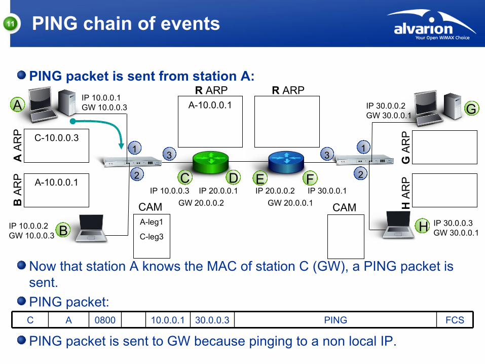
PING packet is sent from station A:
Now that station A knows the MAC of station C (GW), a PING packet is sent.
PING packet:
PING packet is sent to GW because pinging to a non local IP.
FCSPING30.0.0.310.0.0.10800AC
1 1
2
33
2
A
B
C D E F
G
H
IP 10.0.0.1GW 10.0.0.3
IP 10.0.0.2GW 10.0.0.3
IP 10.0.0.3 IP 20.0.0.1 IP 20.0.0.2 IP 30.0.0.1
IP 30.0.0.2GW 30.0.0.1
IP 30.0.0.3GW 30.0.0.1
GW 20.0.0.2 GW 20.0.0.1
C-10.0.0.3
A A
RP
A-10.0.0.1
B A
RP
G A
RP
H A
RP
A-10.0.0.1
R ARP R ARP
A-leg1
C-leg3
CAM CAM

12 PING chain of events
PING packet is arrives to green router from side C:
Green router checks destination address and “IP packet release algorithm” is used.
For a non local destination IP and unknown target MAC, an ARP request is sent to GW as a broadcast through D.
REMARK: The routers in this example don’t have a buffer to keep the original PING request so it is lost.
1 1
2
33
2
A
B
C D E F
G
H
IP 10.0.0.1GW 10.0.0.3
IP 10.0.0.2GW 10.0.0.3
IP 10.0.0.3 IP 20.0.0.1 IP 20.0.0.2 IP 30.0.0.1
IP 30.0.0.2GW 30.0.0.1
IP 30.0.0.3GW 30.0.0.1
GW 20.0.0.2 GW 20.0.0.1
C-10.0.0.3
A A
RP
A-10.0.0.1
B A
RP
G A
RP
H A
RP
A-10.0.0.1
R ARP R ARP
A-leg1
C-leg3
CAM CAM
13 PING chain of events
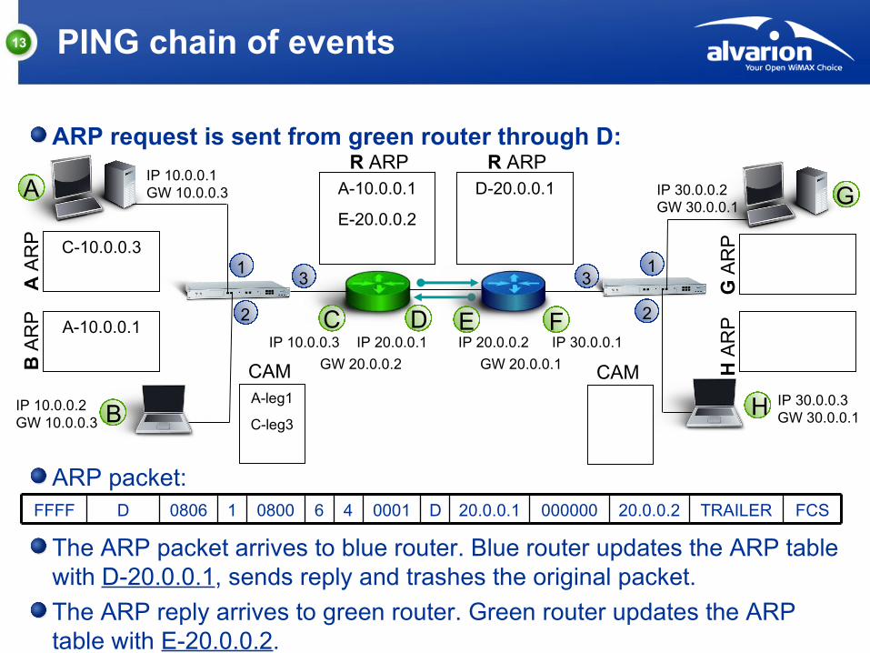
ARP request is sent from green router through D:
ARP packet:
The ARP packet arrives to blue router. Blue router updates the ARP table with D-20.0.0.1, sends reply and trashes the original packet.
The ARP reply arrives to green router. Green router updates the ARP table with E-20.0.0.2.
FCSTRAILER20.0.0.200000020.0.0.1D000146080010806DFFFF
1 1
2
33
2
A
B
C D E F
G
H
IP 10.0.0.1GW 10.0.0.3
IP 10.0.0.2GW 10.0.0.3
IP 10.0.0.3 IP 20.0.0.1 IP 20.0.0.2 IP 30.0.0.1
IP 30.0.0.2GW 30.0.0.1
IP 30.0.0.3GW 30.0.0.1
GW 20.0.0.2 GW 20.0.0.1
C-10.0.0.3
A A
RP
A-10.0.0.1
B A
RP
G A
RP
H A
RP
A-10.0.0.1
E-20.0.0.2
R ARPD-20.0.0.1
R ARP
A-leg1
C-leg3
CAM CAM
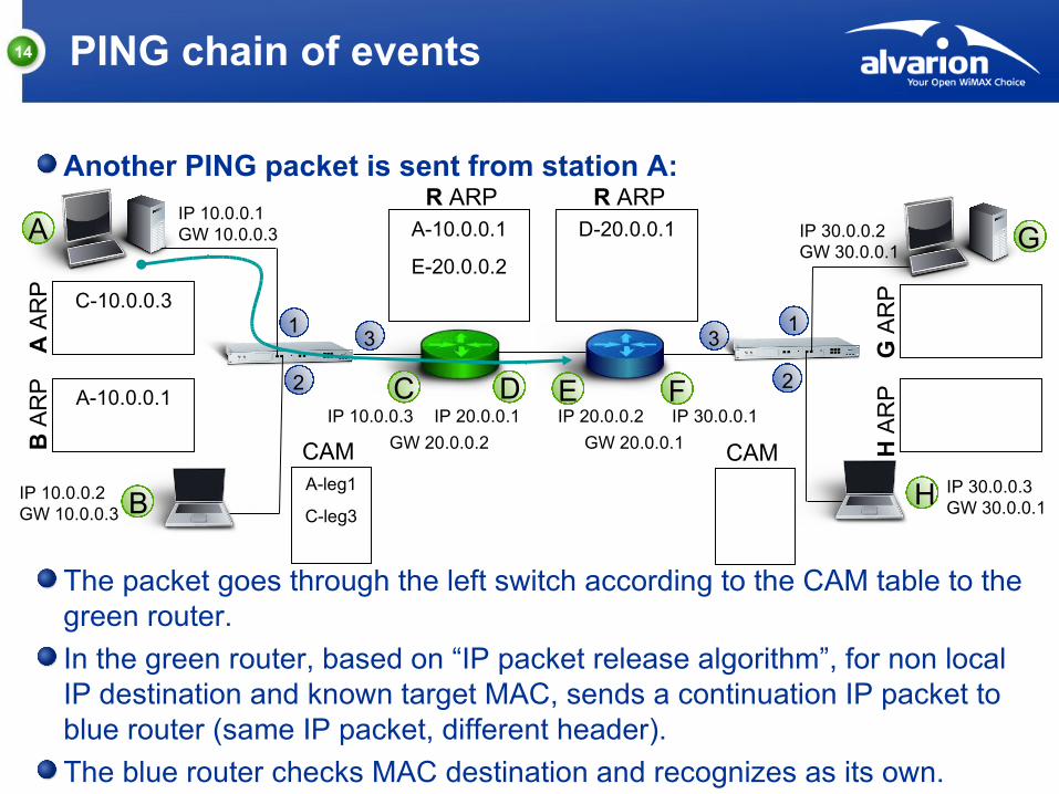
14 PING chain of events
Another PING packet is sent from station A:
The packet goes through the left switch according to the CAM table to the green router.
In the green router, based on “IP packet release algorithm”, for non local IP destination and known target MAC, sends a continuation IP packet to blue router (same IP packet, different header).
The blue router checks MAC destination and recognizes as its own.
1 1
2
33
2
A
B
C D E F
G
H
IP 10.0.0.1GW 10.0.0.3
IP 10.0.0.2GW 10.0.0.3
IP 10.0.0.3 IP 20.0.0.1 IP 20.0.0.2 IP 30.0.0.1
IP 30.0.0.2GW 30.0.0.1
IP 30.0.0.3GW 30.0.0.1
GW 20.0.0.2 GW 20.0.0.1
C-10.0.0.3
A A
RP
A-10.0.0.1
B A
RP
G A
RP
H A
RP
A-10.0.0.1
E-20.0.0.2
R ARPD-20.0.0.1
R ARP
A-leg1
C-leg3
CAM CAM

15 PING chain of events
PING packet is arrives to blue router from side E:
Blue router checks destination address and “IP packet release algorithm” is used.
For a local destination IP and unknown target MAC, an ARP request is sent as a broadcast through F.
1 1
2
33
2
A
B
C D E F
G
H
IP 10.0.0.1GW 10.0.0.3
IP 10.0.0.2GW 10.0.0.3
IP 10.0.0.3 IP 20.0.0.1 IP 20.0.0.2 IP 30.0.0.1
IP 30.0.0.2GW 30.0.0.1
IP 30.0.0.3GW 30.0.0.1
GW 20.0.0.2 GW 20.0.0.1
C-10.0.0.3
A A
RP
A-10.0.0.1
B A
RP
G A
RP
H A
RP
A-10.0.0.1
E-20.0.0.2
R ARPD-20.0.0.1
R ARP
A-leg1
C-leg3
CAM CAM

16 PING chain of events
ARP request is sent from blue router through F:
1 1
2
33
2
A
B
C D E F
G
H
IP 10.0.0.1GW 10.0.0.3
IP 10.0.0.2GW 10.0.0.3
IP 10.0.0.3 IP 20.0.0.1 IP 20.0.0.2 IP 30.0.0.1
IP 30.0.0.2GW 30.0.0.1
IP 30.0.0.3GW 30.0.0.1
GW 20.0.0.2 GW 20.0.0.1
C-10.0.0.3
A A
RP
A-10.0.0.1
B A
RP
G A
RP
H A
RP
A-10.0.0.1
E-20.0.0.2
R ARPD-20.0.0.1
R ARP
A-leg1
C-leg3
CAMF-leg3
CAM
ARP packet:
The ARP packet is a broadcast so the right switch is flooding and send the same packet to the rest of the connected legs.
The right switch updates the CAM table with F-leg3 relation.
FCSTRAILER30.0.0.300000030.0.0.1F000146080010806FFFFF

17 PING chain of events
ARP packet arrives to station G and station H:
1 1
2
33
2
A
B
C D E F
G
H
IP 10.0.0.1GW 10.0.0.3
IP 10.0.0.2GW 10.0.0.3
IP 10.0.0.3 IP 20.0.0.1 IP 20.0.0.2 IP 30.0.0.1
IP 30.0.0.2GW 30.0.0.1
IP 30.0.0.3GW 30.0.0.1
GW 20.0.0.2 GW 20.0.0.1
C-10.0.0.3
A A
RP
A-10.0.0.1
B A
RP
F-30.0.0.1
G A
RP
F-30.0.0.1
H A
RP
A-10.0.0.1
E-20.0.0.2
R ARPD-20.0.0.1
R ARP
A-leg1
C-leg3
CAMF-leg3
CAM
Station G receives the ARP packet and updates the ARP table with F-30.0.0.1 relation. Station G does not send a reply.
Station H receives the ARP packet and updates the ARP table with F-30.0.0.1 relation, sends a reply and trashes the original packet.
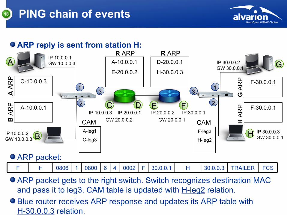
18 PING chain of events
ARP reply is sent from station H:
1 1
2
33
2
A
B
C D E F
G
H
IP 10.0.0.1GW 10.0.0.3
IP 10.0.0.2GW 10.0.0.3
IP 10.0.0.3 IP 20.0.0.1 IP 20.0.0.2 IP 30.0.0.1
IP 30.0.0.2GW 30.0.0.1
IP 30.0.0.3GW 30.0.0.1
GW 20.0.0.2 GW 20.0.0.1
C-10.0.0.3
A A
RP
A-10.0.0.1
B A
RP
F-30.0.0.1
G A
RP
F-30.0.0.1
H A
RP
A-10.0.0.1
E-20.0.0.2
R ARPD-20.0.0.1
H-30.0.0.3
R ARP
A-leg1
C-leg3
CAMF-leg3
H-leg2
CAM
ARP packet:
ARP packet gets to the right switch. Switch recognizes destination MAC and pass it to leg3. CAM table is updated with H-leg2 relation.
Blue router receives ARP response and updates its ARP table with H-30.0.0.3 relation.
FCSTRAILER30.0.0.3H30.0.0.1F000246080010806HF
19
1 1
2
33
2
A
B
C D E F
G
H
IP 10.0.0.1GW 10.0.0.3
IP 10.0.0.2GW 10.0.0.3
IP 10.0.0.3 IP 20.0.0.1 IP 20.0.0.2 IP 30.0.0.1
IP 30.0.0.2GW 30.0.0.1
IP 30.0.0.3GW 30.0.0.1
GW 20.0.0.2 GW 20.0.0.1
C-10.0.0.3
A A
RP
A-10.0.0.1
B A
RP
F-30.0.0.1
G A
RP
F-30.0.0.1
H A
RP
A-10.0.0.1
E-20.0.0.2
R ARPD-20.0.0.1
H-30.0.0.3
R ARP
A-leg1
C-leg3
CAMF-leg3
H-leg2
CAM
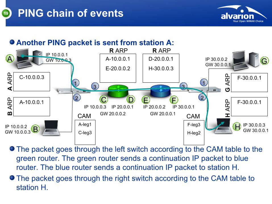
PING chain of events
Another PING packet is sent from station A:
The packet goes through the left switch according to the CAM table to the green router. The green router sends a continuation IP packet to blue router. The blue router sends a continuation IP packet to station H.
The packet goes through the right switch according to the CAM table to station H.

20
1 1
2
33
2
A
B
C D E F
G
H
IP 10.0.0.1GW 10.0.0.3
IP 10.0.0.2GW 10.0.0.3
IP 10.0.0.3 IP 20.0.0.1 IP 20.0.0.2 IP 30.0.0.1
IP 30.0.0.2GW 30.0.0.1
IP 30.0.0.3GW 30.0.0.1
GW 20.0.0.2 GW 20.0.0.1
C-10.0.0.3
A A
RP
A-10.0.0.1
B A
RP
F-30.0.0.1
G A
RP
F-30.0.0.1
H A
RP
A-10.0.0.1
E-20.0.0.2
R ARPD-20.0.0.1
H-30.0.0.3
R ARP
A-leg1
C-leg3
CAMF-leg3
H-leg2
CAM
PING chain of events
PING reply packet is sent from station H to station A:
The packet goes through the right switch according to the CAM table to the blue router. The blue router sends a continuation IP packet to green router. The green router sends a continuation IP packet to station A.
The packet goes through the left switch according to the CAM table to station A.
21
1 1
2
33
2
A
B
C D E F
G
H
IP 10.0.0.1GW 10.0.0.3
IP 10.0.0.2GW 10.0.0.3
IP 10.0.0.3 IP 20.0.0.1 IP 20.0.0.2 IP 30.0.0.1
IP 30.0.0.2GW 30.0.0.1
IP 30.0.0.3GW 30.0.0.1
GW 20.0.0.2 GW 20.0.0.1
C-10.0.0.3
B-10.0.0.2A A
RP
A-10.0.0.1
C-10.0.0.3B A
RP
F-30.0.0.1
H-30.0.0.3G A
RP
F-30.0.0.1
G-30.0.0.2
H A
RP
A-10.0.0.1
E-20.0.0.2
B-10.0.0.2
R ARPD-20.0.0.1
H-30.0.0.3
G-30.0.0.2
R ARP
A-leg1
C-leg3
B-leg2
CAMF-leg3
H-leg2
G-leg1
CAM
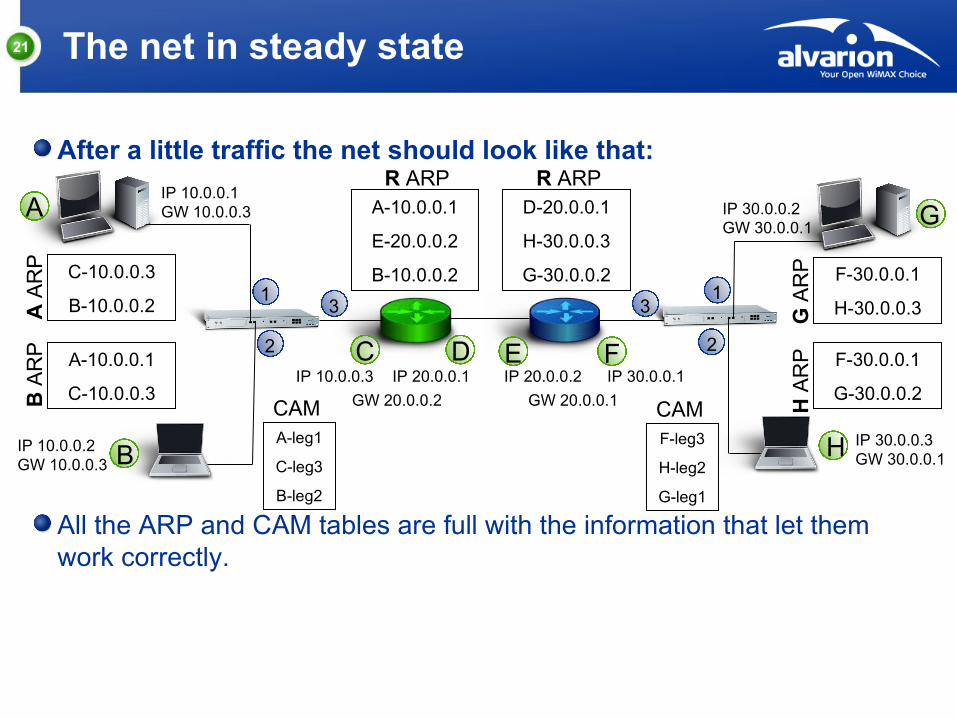
The net in steady state
After a little traffic the net should look like that:
All the ARP and CAM tables are full with the information that let them work correctly.

© Copyright Alvarion Ltd.
Thank You