pipe in pipe swaged welding new design by subsea 7
DESCRIPTION
New swaged sleeve welding in pipe in pipe welding - presentation.TRANSCRIPT

OTC2013 - 24077Swaged Field Joint Development for Reel Lay
Venu Rao, John Mair, Dr Sriskandarajah, Richard Jones, Paul Booth, Subsea 7, Christian Geertsen, ITP Interpipe SA

CONTENTS
Slide 2
24077 • Swaged Field Joint Development for Reel Lay• Venu Rao
Ø
Ø
Ø
Ø
Ø
Ø Failure Mode AnalysesØ

Introduction - Enhanced Thermal Performance Pipe-in-pipe (PIP)
Slide 3
24077 • Swaged Field Joint Development for Reel Lay• Venu Rao
Insulation Blanket: ITP Izoflex Steel Sheath for protectionReduced Pressure in Annulus No Centralisers required
Non ageing (Silica based - mineral)
Superior thermal performance Izoflex: U-value = 0,30 W/m2.K (on OD) Aerogels: U-value = 0,74 W/m2.K (on OD)* PU Foam: U-value = 1,25 W/m2.K (on OD)Load bearing insulation: No centralizers
Suitable for large range of temperature (-196°C [ + 900°C)

Swaged Field Joint - DNV Qualification
Slide 4
24077 • Swaged Field Joint Development for Reel Lay• Venu Rao
Outer Pipe323.9 x 14.3X52
Inner Pipe219.1 x 12.7X65Izoflex
Epoxy Resin
Half-shells323.9 x 14.3X52 Water stops are dictated
for many PIP prospects
Swaged Field Joint allows drawdown plus provides a more secure waterstop
DNV qualification completed.
Objectives of FE Analysis
Slide 5
24077 • Swaged Field Joint Development for Reel Lay• Venu Rao
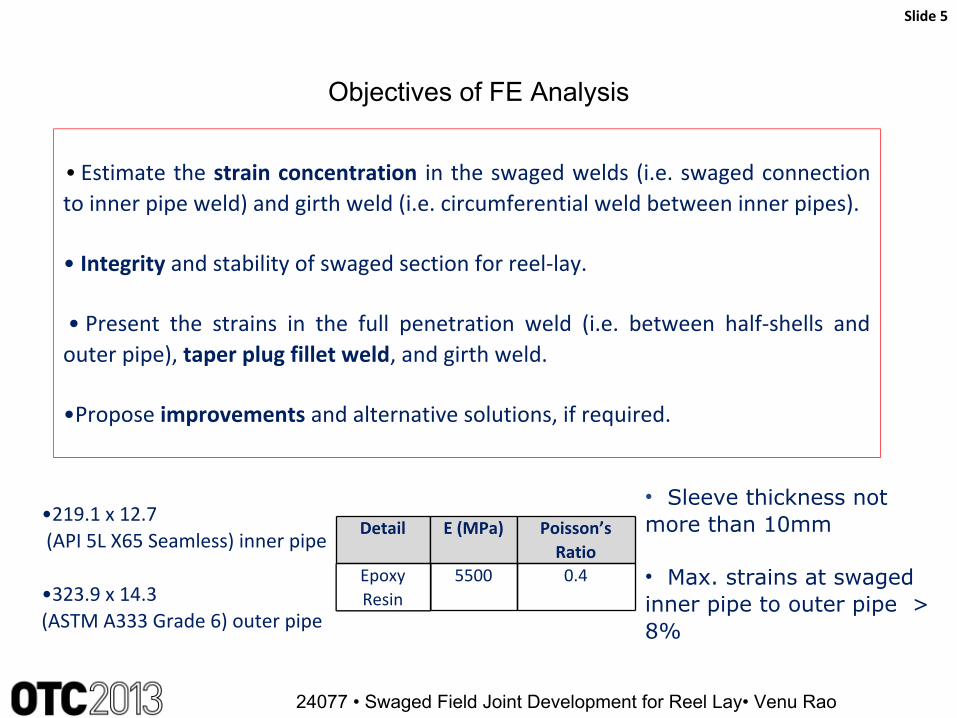
• Estimate the strain concentration in the swaged welds (i.e. swaged connection to inner pipe weld) and girth weld (i.e. circumferential weld between inner pipes).
• Integrity and stability of swaged section for reel-lay.
• Present the strains in the full penetration weld (i.e. between half-shells and outer pipe), taper plug fillet weld, and girth weld.
•Propose improvements and alternative solutions, if required.
•219.1 x 12.7 (API 5L X65 Seamless) inner pipe
•323.9 x 14.3(ASTM A333 Grade 6) outer pipe
Detail E (MPa) Poisson’s Ratio
Epoxy Resin
5500 0.4
• Sleeve thickness not more than 10mm
• Max. strains at swaged inner pipe to outer pipe > 8%

Objectives of FE Analysis
Slide 6
24077 • Swaged Field Joint Development for Reel Lay• Venu Rao
-10-8-6-4-202468
10
0 100 200 300 400 500 600 700 800 900
Strain (%)
True Distance along the Path
Swaged Connection - Inner Pipe Strain Variation
Tension-Extrados Tension-IntradosCompression-Extrados Compression-Intrados

Objectives of FE Analysis
Slide 7
24077 • Swaged Field Joint Development for Reel Lay• Venu Rao
-10-8-6-4-202468
10
0 100 200 300 400 500 600 700 800 900
Strain (%)
True Distance along the Path
Swaged Connection - Inner Pipe Strain Variation
Tension-Extrados Tension-IntradosCompression-Extrados Compression-Intrados
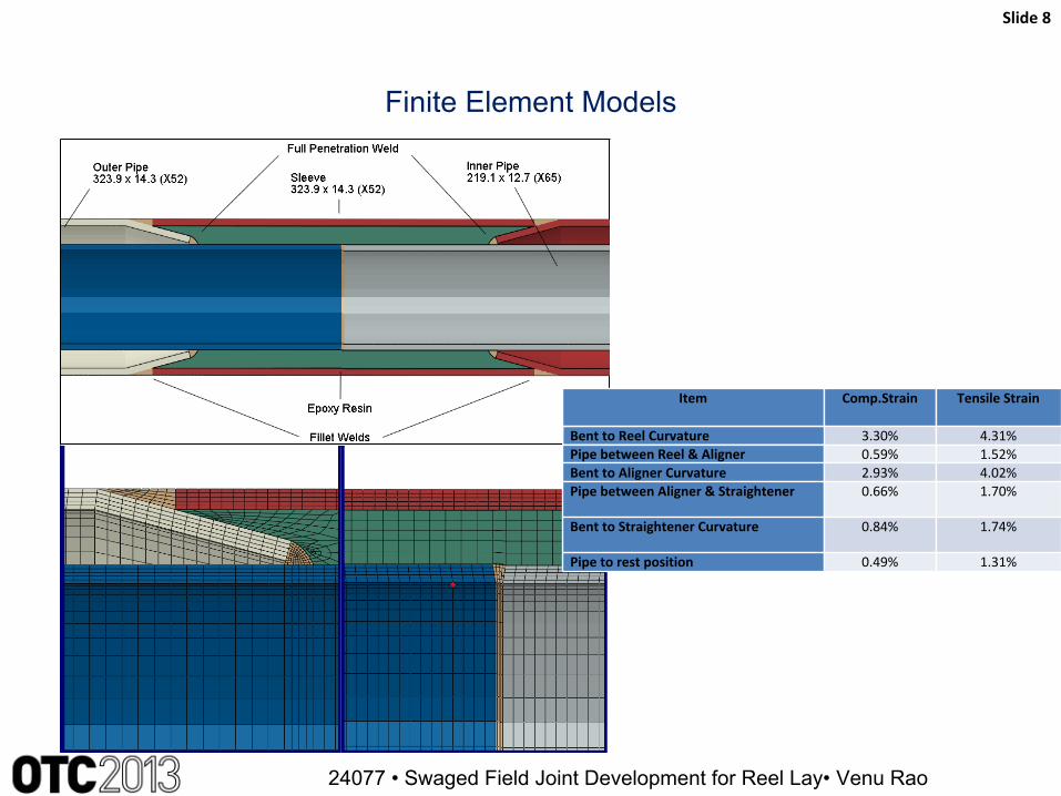
Finite Element Models
Slide 8
24077 • Swaged Field Joint Development for Reel Lay• Venu Rao
Item Comp.Strain Tensile Strain
Bent to Reel Curvature 3.30% 4.31%Pipe between Reel & Aligner 0.59% 1.52%Bent to Aligner Curvature 2.93% 4.02%Pipe between Aligner & Straightener 0.66% 1.70%
Bent to Straightener Curvature 0.84% 1.74%
Pipe to rest position 0.49% 1.31%

Swaged Field Joint - DNV Qualification
Slide 9
24077 • Swaged Field Joint Development for Reel Lay• Venu Rao
Ø A rigorous DNV Qualification and Verification process was initiated as per DNV-RP-A203.
Ø Systematic approach of qualification was carried out by DNV as an independent body.

FE Analysis Results
Slide 10
24077 • Swaged Field Joint Development for Reel Lay• Venu Rao
Ø High strain region in the outer pipe is outside the swaged connection (~2.8%)
Ø Sleeve strains : -0.49% / 1.09%.
Ø No local deformations
Ø Epoxy provides volumetric constraint and does not offer much stiffness.
Ø The assembly can be reeled with and without epoxy resin.
Failure Mode Analyses
Slide 11
24077 • Swaged Field Joint Development for Reel Lay• Venu Rao
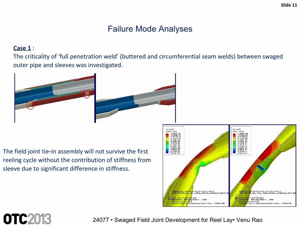
Case 1 :The criticality of ‘full penetration weld’ (buttered and circumferential seam welds) between swaged outer pipe and sleeves was investigated.
The field joint tie‑in assembly will not survive the first reeling cycle without the contribution of stiffness from sleeve due to significant difference in stiffness.

Failure Mode Analyses
Slide 12
24077 • Swaged Field Joint Development for Reel Lay• Venu Rao
Case 2 :Keeping the sleeve intact and removing one of the taper (swaged end) welds and applying axial load equal to the one stalk weight, i.e.400Te.
Alternative load paths are available and the integrity of the swaged field joint is ensured.

Swaged Field Joint - DNV Qualification
Slide 13
24077 • Swaged Field Joint Development for Reel Lay• Venu Rao

Objectives & Strategies for Full Scale Tests
Slide 14
24077 • Swaged Field Joint Development for Reel Lay• Venu Rao
Objectives§ Ensure swaged weld integrity
• Inner pipe & Outer pipe integrity• Soundness of the weld
§ Application of a AUT system & procedure to inspect all the weld and its vicinity
Strategies§ Subsea7 / ApplusRTD Co-development§ AUT System & Procedure Validated by Third Party (DnV)§ Enhanced Sizing Accuracy & POD§ Application of fitness for purpose criteria (ECA)§ Application of supplementary NDT methods if necessary

Weld Types
Slide 15
24077 • Swaged Field Joint Development for Reel Lay• Venu Rao
4 5
2 3
1
6 7810 11 12 13
2 3
4 56 79
Welds Designation Welding Processes Inspection methodology Inspection qualification status
1 Inner Pipe to Pipe Weld
Mechanised PGMAW Pipe end inspection by UT/MPI
Weld inspection by AUT
All inspection techniques established and validated
AUT inspection subject to project validation
2 and 3 Swaged End Welds Manual GTAW/ Semi Auto GSFCAW
Manual Ultrasonic Testing (MUT) or Semi Automatic UT
AUT inspection subject to project validation
4 and 5 Buttered Welds Mechanised GSFCAW Manual UT Procedure developed and qualified
6 and 7 Circumferential Seam Welds
Manual GTAW/ Semi Auto GSFCAW
Manual UT Procedure developed and qualified
8 and 9 Long Seam Welds Manual GTAW/ Semi Auto GSFCAW
Manual UT Inspection technique established and validated
10 - 13 Plug Seal Welds Manual GTAW MPI and/or Eddy current Inspection technique established and validated
DNV identified Welds 4,5,6 & 7 are critical from FMIRR analysis.
8 Critical Defects and Acceptance Criteria
Slide 16
24077 • Swaged Field Joint Development for Reel Lay• Venu Rao
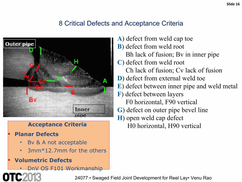
A) defect from weld cap toeB) defect from weld root Bh lack of fusion; Bv in inner pipeC) defect from weld root Ch lack of fusion; Cv lack of fusionD) defect from external weld toeE) defect between inner pipe and weld metalF) defect between layers F0 horizontal, F90 verticalG) defect on outer pipe bevel lineH) open weld cap defect H0 horizontal, H90 verticalAcceptance Criteria
§ Planar Defects• Bv & A not acceptable• 3mm*12.7mm for the others
§ Volumetric Defects• DnV OS F101 Workmanship

DNV Qualification
Slide 17
24077 • Swaged Field Joint Development for Reel Lay• Venu Rao
Welds 4 & 5:Welding, inspection of weld buttering was done in two stages. 1) Weld metal is deposited and dressed to allow for full volumetric inspection. 2) Manual UT was performed using angles shear wave and 0 degree compression wave probes.
Welds 6 & 71) Circumferential weld inspection by full UT2) Longitudinal seam weld my Manual UT.
Total cumulative plastic strain limits were established by rigorous FEA.
Post bend tests validation FEA were performed and the strains were in agreement with test results.
Failure Mode Sensitivity Analyses were performed to address the issue of transfer of loads from Weld 2 to Weld 3 or vice versa. Based on analysis results, DNV recommended to use resin in the half shells for additional support / resistance.
Thermal expansion effects were demonstrated to satisfy design requirements.

Summary and Conclusions
Slide 18
24077 • Swaged Field Joint Development for Reel Lay• Venu Rao
Ø The reelable swaged-ends Pipe-in‑Pipe system was developed identifying uncertainties in the system with extensive testing and associated finite element analyses. Extensive post bend validation FEA was carried out using data from strain gauges.
Ø The swaged field joint provides water tight connection and hence can act as a waterstop.Ø It acts as a pressure barrier in the event of wet buckling and rupture of outer pipe i.e. buckle
arrestor.Ø It acts as reelable intermediate bulkhead for loadsharing between inner & outer pipes.Ø The swaged field joint development was awarded DNV “Certificate of Fitness for Service”
affirming that the new technology is qualified in accordance with DNV‑RP‑A203 along with DNV’s conditions of acceptance.

Acknowledgements / Thank You / Questions
Paper # • Paper Title • Presenter Name
Subsea 7ITP InTerPipe SA
Tata SteelApplusRTD
DNV
Slide 19