pipe inspection robot using an inch-worm mechanism with...
TRANSCRIPT
ICCAS2005 June 2-5, KINTEX, Gyeonggi-Do, Korea
Pipe Inspection Robot Using an Inch-Worm Mechanism with
Embedded Pneumatic Actuators
Chang-Hwan Choi, Seung-Ho Jung and Seung-Ho Kim
Nuclear Robotics Lab., KAERI, Daejeon 305-353, Korea
(Tel: +82-42-868-8836; Fax: +82-42-868-8833; Email:{madistcch, shjung2, robotkim}@kaeri.re.kr)
Abstract: The outlet feeder pipe thinning in a PHWR (Pressurized Heavy Water Reactor) is caused by high pressure steam
flow inside the pipe, which is a well known degradation mechanism called FAC (Flow Assisted Corrosion). In order to monitor
the degradation, the thickness of the outlet bends closed to the exit of the pressure tube should be measured and analyzed at
every official overhaul. This paper develops a mobile feeder pipe inspection robot that can minimize the irradiation dose of
human workers by automating the measurement process. The robot can move by itself on the feeder pipe by using an inch
worm mechanism, which is constructed by two gripper bodies that can fix the robot body on the pipe, one extendable and
contractable actuator, and a rotation actuator connected the two gripper bodies to move forward and backward, and to rotate
in the circumferential direction
Keywords: inch-worm, pipe inspection, feeder pipe, nuclear robot
1. IntroductionThe outlet feeder pipe thinning in a PHWR (Pressurized
Heavy Water Reactor) is caused by high pressure steam flow
inside the pipe, which is a well known degradation mech-
anism called FAC (Flow Assisted Corrosion). In order to
monitor the degradation, the thickness of the outlet bends
closed to the exit of the pressure tube should be measured
and analyzed at every official overhaul. However, collect-
ing high quality data is a challenge, mainly due to lack of
space around the pipes, especially for 2.5 inch pipes and the
roughness of feeder pipes. Moreover, although the reactor is
shutdown in the overhaul period, the radiation dose is severe
near the feeder pipe because they are located in front of the
reactor.
Ontario Hydro’s SIMD department developed SIMD bracelet
and used it in Gentilly-2 from 1997 to 1999 for inspecting
the feeder pipe thinning problem [1]. However, the SIMD
bracelet can only be applied at 2 inch feeder pipes and espe-
cially on the first bends because of the limited space around
the feeders. Therefore, the data quality of the inspection is
not enough for guaranteeing the safety of the feeder pipes.
Hydro Quebec research center (IREQ) developed an inspec-
tion system, METAR and used it in Gentilly-2 from 1999
to 2000 [1]. METAR has 14 ultrasonic sensors mounted on
holders in each sensor. The holder maintains the sensor to
be attached perpendicular with respect to the feeder pipe
and allows some amount of freedom by using a flexible collar
to fixing the holders. The SIMD bracelet and METAR are
operated manually, that is, since the inspection systems have
no motorizing capabilities, a human worker should install the
system and stay in front of the feeder pipe while completing
the measurement, which increases the irradiation dose of the
workers.
This paper develops a mobile feeder pipe inspection robot
that can minimize the irradiation dose of a human worker
This paper is supported by the Korea Atomic Energy Research Institute as
a project of “The Development of Radiation Hardened Robot for Nuclear
Facility” sponsored by the Ministry of Science and Technology.
by automating the measurement process. The robot can
move by itself on the feeder pipe by using an inch worm
mechanism [2][3], which is constructed by two gripper bod-
ies that can fix the robot body on the pipe and one exten-
sion/contraction actuator and a rotation actuator connected
the two gripper bodies to move forward and backward and to
rotate in the circumferential direction. Those actuators are
drived pneumatically which are embedded inside the robot
body to reduce the size of the robot so that it is applicable
to the actual feeder pipes in the PHWR.
The design method of the robot is presented based on the
analysis of the working environment in a PHWR to deter-
mine the size and functions of the robot. The kinematic
analysis gives an insight of the relation between the robot
size and allowable feeder pipe curvature. The control sys-
tem is developed by using five directional control valves and
a microcontroller with five MOSFET solenoid drivers. The
proposed inspection robot is applied to a mockup of a feeder
pipe to illustrating the feasibility of the inspection.
2. Working environment analysisThe PHWR in Korea has 380 pressure tubes. The feeder
pipes are attached in each pressure tube whose diameters
are 1.5, 2.0, 2.5 inches with the number by 33, 183, 164,
respectively. The direction and curved angle of the feeder
pipe is various. Figure 1(a) shows a part of the pressure
tube array. The pressure tubes are arranged circularly with
the interval distance by 286 mm each other. The distance
to reach the feeder pipe from the front face of the pressure
tube is about 413 mm. The robot should be able to pass
the space among the pressure tubes and the guides to fix the
feeder pipes to reach the surface of the feeder pipe, whose
size is approximately 155 mm × 204 mm.
Figure 1(b) shows the interference of a feeder pipe with other
feeder pipes, pressure tubes, and guides, when the inspection
robot travels the feeder pipe. The cross section view of a
2.5 inch feeder pipe is described because it has more severe
interference than 2.0 and 1.5 inch pipes. Therefore, in order

���
���
���
Pressure tube
Feeder pipe
(a)
(b)
�����
���
Fig. 1. (a) Feeder pipe array in a PHWR (b) The cross-
section view of a closest gap in the array.
to inspect the feeder pipe, the robot can travel such gaps.
The inner part of the curved pipe has more space than the
outer part. In conclusion, the robot should be able to pass
through 7.6 mm gaps and the thickness of the robot body
should not exceed more than 14.63 mm.
Since the feeder pipe in the PHWR is made by bending a spe-
cial steel pipe of 1.5, 2.0, and 2.5 inch sizes, the cross-section
of the pipe at the curved part becomes elliptical shape, that
is, the in-plane curved part of the feeder pipe has wide di-
ameter, and the out-plane curved part has small diameter
compared with the nominal diameter. Figure 2 shows the
distance and contact angle changes of the ultra-sonic sen-
sor to maintain perpendicularity with respect to the feeder
pipe. This contact distance and angle variation should be
considered for designing the robot and the sensor mecha-
nism. Table 1 shows the measured diameter of an actual
2.5 inch feeder pipe at the first and second parts of bending.
Since the curvature of the feeder pipe is various, only the
maximum case is described. The maximum diameter change
is 6.3 mm at the second bending as shown in the table.
When the sensor is located at the angle θ, if the pipe is per-
fectly a circle, the ultra sonic sensor is located at s1. If the
pipe is changed to an elliptical shape, the sensor is located at
Table 1. The diameter change caused by the bending of the
pipe.
unit (mm) Nominal first bend second bend
minimum 73.1 68.15 66.8
maximum - 77.25 77.1
curvature - 92.25 -
a
r
b
mxy =
222 ryx =+
12
2
2
2
=+b
y
a
x
1s2s
αd
θ x
y
Fig. 2. (a) The measurement of the diameter at the 1st and
2nd bending in a feeder pipe mockup (b) The variation
of ultra-sonic sensor attachment caused by the bending.
s2, and the position and contact angle of the sensor should
be changed by d and α, respectively, to maintain the per-
pendicular contact with the pipe. The relation between the
amount of the diameter change with the required distance
and angle of the sensor can be obtained from the geometric
analysis. The distance change caused by the bending is
d = r −√
(1 + m2)a2b2
b2 + a2m2. (1)
The contact angle variation is
α = tan−1
(− 1
m
)− tan−1
(− b2
a2
1
m
)(2)
where m = tan θ.
Assume that the area of the pipe is not changed caused by
bending, the contact distance and angle changes with respect
0 10 20 30 40 50 60 70 80 90-6
-4
-2
0
2
4
6
0 10 20 30 40 50 60 70 80 90-20
-15
-10
-5
0
5(deg)θ (deg)θ
d(m
m)
(deg)θ (deg)θ
�(d
eg)
(a)
(b)
��������
����������
���� ���� �
������������
�� ���������
�
�
�
Fig. 3. (a) The distance variation (b) contact angle variation
caused by the pipe distorsion.

to various pipe distortions are analyzed as shown in Fig. 3
which is from Eq. (1) and Eq. (2). The plot 2 is the result
for the actual feeder pipe. The distance and angle change
will be by 1.48 mm and 5.8 deg when θ becomes 60 deg,
respectively.
3. Structure of the Feeder PipeInspection Robot
3.1. Structure of the robot
There are various actuation mechanism to design a robot
such as electrical motor, pneumatic cylinders, hydraulic ac-
tuators, and material forces, and so on. Although the electri-
cal system has many benefits, the smaller the actuator, the
smaller the actuator force. That is, we can make the robot as
small as possible, but the robot may not working in an actual
environment which has various harsh conditions that require
large force. The material forces generated by a piezoelec-
tric and magnetostrictive material are a good actuator only
for sub-millimeter or sub-micrometer applications. The hy-
draulic actuators is relatively large forces with small volume,
but the contamination is the main problem. The pneumatic
actuators are good at generating a large force and preventing
from contamination. Therefore, the pneumatic actuators are
used for robot design.
The working environment of the robot is one of the most haz-
ardous environment that a robot can meet because of the
large radiation dose, complex mechanical constraints, and
requirement of high precision measurement. The robot can
be able to travel along that environment. In this paper, we
designed a robot using pneumatic actuators which is em-
bedded into the robot body, which reduces the robot size
dramatically.
An inch-worm mechanism is used for the moving mechanism
as shown in Fig. 4. The robot is constructed by four actu-
ation parts. Two gripper actuators are located at the front
Air
Front gripper
E/C actuatorRotation actuator
Rear gripper
Fig. 4. Feeder pipe inspection robot using an inch-worm
mechanism.
and rear parts of the robot body for fixing the robot to the
feeder pipe. Each gripper actuator has two half-circle shaped
gripper hand to encloses the pipe. The gripper hand is drived
by two pneumatic cylinders with opposite direction. When
air pressure is applied to the gripper body, the cylinder ex-
pands and moves the gripper hands in the fixing direction.
When the air is released, the cylinder moves back by spring
force.
The gripper is designed to be able to be opened by apply-
ing external force so that it can be easily installed as shown
in Fig. 5. The human worker or installation equipment just
push the robot for installation and pull the robot for releas-
ing.
Fig. 5. The installation of the feeder pipe inspection robot.
A motorizing mechanism connects the two gripper bodies,
which is constructed as an extendable/contractable actuator
(E/C actuator) and a rotation actuator in the middle of the
two gripper bodies for moving forward and backward, and
for rotating circularly along the circumference direction of a
feeder pipe, respectively.
In order to adopt to various radius of curvature of the feeder
pipes, the grippers and the motorizing mechanism are con-
nected by free revolute joints so that the front and rear grip-
pers can be formed any angle with respect to the motorizing
mechanism by mechanical constraints with the curved feeder
pipe. This mechanism gives self-adjusting of the orientation
of the robot body so that the robot body is always placed
at the outer side of the curved feeder pipe, which is an ideal
case like the inner diameter of the gripper is almost same as
the outer diameter of the feeder pipe and the feeder pipe has
no variation on the diameter, even though at the curved sec-
tion. However, since the inner diameters of the grippers are
limited by the maximum diameter of a curved feeder pipe as
shown in Fig. 2, there are some amount of gaps between the
grippers and feeder pipes, which prevents the self-adjusting
of the orientation. Therefore, a motorizing mechanism is
required to adjust the orientation of the robot.
Figure 6(a)-(c) show the moving principle of the inch-worm
feeder pipe robot. In order to move to the right direction, the
rear gripper is fixed by extending the cylinder, then, extend-
ing the E/C actuator, fixing the front gripper, releasing the
rear gripper, contracting the E/C actuator. This operation
is continued to move further and the operation is reversed if
the direction is left. Figure 6(d)-(f) show the rotation prin-
ciple. In order to rotate in cw (clock wise) direction, the rear

(a)
(b)
(c)
(d)
(e)
(f)
Fig. 6. Feeder pipe inspection robot using an inch-worm
mechanism.
gripper is fixed, then, rotating the rotation actuator in cw
direction, fixing the front gripper, releasing the rear gripper,
rotating the rotation actuator in ccw (counter clock wise)
direction. This operation is continued to rotate further and
the operation is reversed if the direction is cw. Since the
robot can move freely in the longitudinal and circumferen-
tial directions of a feeder pipe, we can measure most of the
part on the feeder pipe if the space is allowed except the in-
ner part of the curved feeder pipe, which cannot be accessed
because of the mechanical constraints.
3.2. Robot Design
The robot should be move along a curved pipe with relatively
small curvature as listed in Table 1. In order to determine
the size of the robot that can be travel along the target feeder
pipe, a kinematic analysis is performed as shown in Fig. 7.
The vector P3 can be represented as
P3 = v01 + A0
1v12 + A0
1A12P
23. (3)
Assume that the θ1 is π/2, that is, the robot is located at
the top of the circular pipe, then the x position of the P3
should be larger than zero (P3x > 0) and the mechanical
constraints, that is, the gripper is aligned perpendicularly
with respect to the feeder pipe gives
l12
+ l3 cos θ2 − r3 sin θ2 > 0 (4)
r1 sin θ2 − l12
cos θ2 − l2 = 0. (5)
where, r3 = rp + lg + lh, l2 = l3 + lw/2. Here, rp, lg, lh,
and lw are radius of the feeder pipe, the gap between the
outer radius of the feeder pipe and the inner radius of the
robot, the height of the gripper, and the length of the gripper
bodies, respectively. l3, r3, and l2 are the x and y position
of P2 and P3 with respect to x2 − y2 coordinate system.
Changing the inequality of Eq. (4) to an equality condition
for plotting the graph and rearranging Eqs. (4) and (5) gives
[l1
l3
]=
[12
cos θ2
− 12
cos θ2 −1
]−1 [r3 sin θ2
lw2− r1 sin θ2
]. (6)
Computing the Eq. (6) with respect to θ2 and plotting the
result with respect to the l1 and l3 gives Fig. 8. Seven cases
of the feeder pipe bending curvature are plotted, which are
60, 65, 70, 80, 90, 92.25, and 100 mm. The right area of
each plot represents the feasible region, for example, assume
that the designed robot’s l1 and l3 are 27 mm and 9 mm,
which are at the left side of the plot representing the bending
curvature of 70 mm, so the robot can travel the curved pipe
whose curvature is larger than 70 mm. However, since the
design is at the right side of the plot representing the bending
curvature of 65 mm, the robot cannot travel along the pipe.
The designed robot is at the left side of the curvature with
92.25 mm, it can travel along the feeder pipe that are going
to be inspected.
4. Controller DesignThe robot has six degree of freedom including four active
joints controlled by the body embedded pneumatic actuators
x0
y0
x1
y1
x2
y2
P3
l1/2
(l3, r3)2
r1 (l2, 0)2P4
P2 (l2, r3)2
Fig. 7. The kinematic analysis for verifying the relationship
between the robot size and the pipe curvature.
0 5 10 15 20 25 30 35 40 45 500
5
10
15
20
25
30
35
40
45
50
l1 (mm)
l3 (
mm
)
�������
���
�
��
Fig. 8. The relation between the pipe curvature and the size
of the robot.
and two free joint which are constrained by the curved pipe.
The four active joints are composed of six pneumatic cylin-
ders. Two for front and rear grippers, two for E/C actuator,
and two for rotation actuator. The gripper has gripping and
releasing motion, which can be controlled by using one five
ports directional control valve. The E/C actuator has expan-
sion and contraction motion, which can be controlled by one
five ports directional control valve. The rotation actuator
has cw rotation, ccw rotation, and center position, which is
controlled by two five port directional control valves. There-
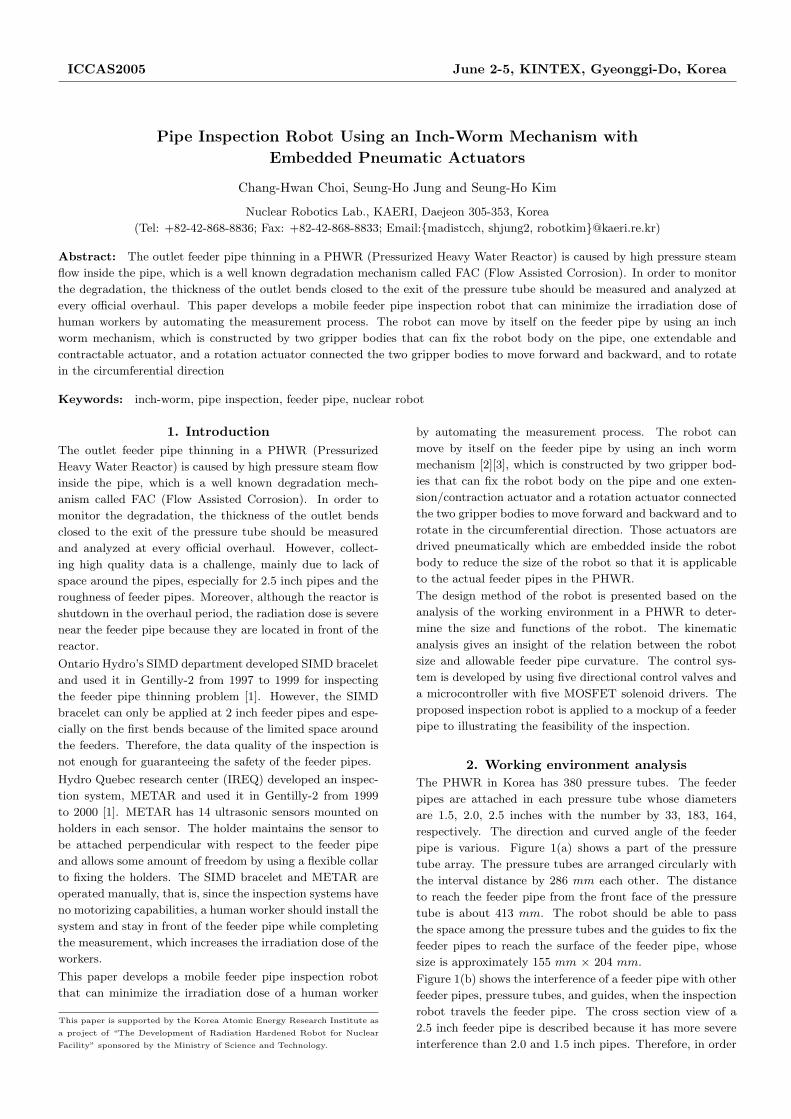
fore, five valves are used for robot control. Figure 9 shows
the block diagram of the robot controller. The valves are
drived by using five MOSFETs. The switching sequence of
the MOSFETs are controlled by using an ATMega128, an
AVR microcontroller made by the Atmel co. ltd. The com-
mand can be transferred from PC through RS-232 port and
from control panel composed of switches for movement and
rotation direction control, and a potentiometer for velocity
control.
Table 2 shows the switching sequence for forward and back-
ward movement. the sequence 0 is a normal condition that
fixes the robot to the feeder pipe so that the robot can-
not be slipped down. The ‘H’ and ‘L’ mean that the valve
is switched on and off, respectively, which mean that the
air pressure is supplied or not. Table 3 shows switching se-
quence for cw and ccw rotation motion. In case of rotation,
the nominal condition is the center position of the rotation
actuator. Since no air pressure is applied at sequence 0, the
position is determined by the spring forces. These sequence
tables are included in the control program.
Table 2. The switching sequence for forward and backward
movement.
Seq. Forward Backward
RG E/C FG RG E/C FG
0 H L H H L H
1 H L L L L H
2 H H L L H H
3 H H H H H H
4 L H H H H L
5 L L H H L L
Table 3. The switching sequence for cw and ccw rotation.
Seq. cw ccw
RG CW CCW FG RG CW CCW FG
0 H L L H H L L H
1 H L L L H L L L
2 H H L L H L H L
3 H H L H H L H H
4 L H L H L L H H
5 L L L H L L L H
���������
������
���
���
��� ����
���������
��������������
�������������
��������������
�������� ���
!����� ���
����
����
����
����
� ���
�� ��
"�������#��#����$��$�
�% ��&������
Fig. 9. Pneumatic feeder pipe inspection robot.
������������������������
����������������
�� �������� �������� �������� ������
����������� ����������� ����������� �����������
������������������������
� ������� ������� ������� ������
������������
Fig. 10. The experimental setup.
5. ExperimentsFigure 10 shows the experimental setup for motion control.
The air supply by the air compressor flows through the reg-
ulator that is equipped with the air filter. The filtered air
is supplied to the directional control valves. The MOSFETs
controlled by the AVR microcontroller control the air flow
that is applied to the robot.
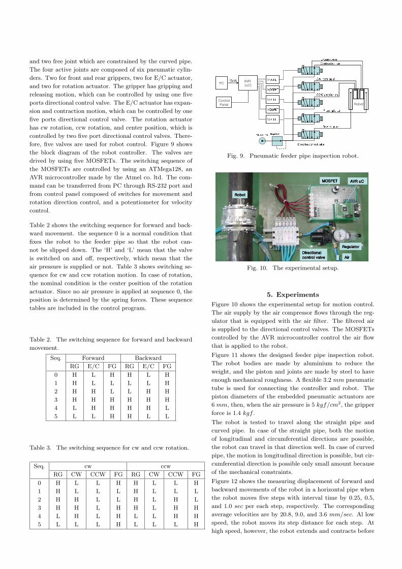
Figure 11 shows the designed feeder pipe inspection robot.
The robot bodies are made by aluminium to reduce the
weight, and the piston and joints are made by steel to have
enough mechanical roughness. A flexible 3.2 mm pneumatic
tube is used for connecting the controller and robot. The
piston diameters of the embedded pneumatic actuators are
6 mm, then, when the air pressure is 5 kgf/cm2, the gripper
force is 1.4 kgf .
The robot is tested to travel along the straight pipe and
curved pipe. In case of the straight pipe, both the motion
of longitudinal and circumferential directions are possible,
the robot can travel in that direction well. In case of curved
pipe, the motion in longitudinal direction is possible, but cir-
cumferential direction is possible only small amount because
of the mechanical constraints.
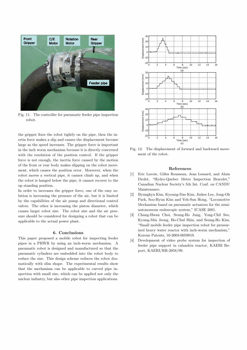
Figure 12 shows the measuring displacement of forward and
backward movements of the robot in a horizontal pipe when
the robot moves five steps with interval time by 0.25, 0.5,
and 1.0 sec per each step, respectively. The corresponding
average velocities are by 20.8, 9.0, and 3.6 mm/sec. Al low
speed, the robot moves its step distance for each step. At
high speed, however, the robot extends and contracts before
����������������
����������������������������
������������
����������������������������� �� �� �� �
������������
��������������������
������������
��������������������������������������������
Fig. 11. The controller for pneumatic feeder pipe inspection
robot.
the gripper fixes the robot tightly on the pipe, then the in-
ertia force makes a slip and causes the displacement become
large as the speed increases. The gripper force is important
in the inch worm mechanism because it is directly concerned
with the resolution of the position control. If the gripper
force is not enough, the inertia force caused by the motion
of the front or rear body makes slipping on the robot move-
ment, which causes the position error. Moreover, when the
robot moves a vertical pipe, it cannot climb up, and when
the robot is hanged below the pipe, it cannot recover to the
up standing position.
In order to increases the gripper force, one of the easy so-
lution is increasing the pressure of the air, but it is limited
by the capabilities of the air pump and directional control
valves. The other is increasing the piston diameter, which
causes larger robot size. The robot size and the air pres-
sure should be considered for designing a robot that can be
applicable to the actual power plant.
6. ConclusionsThis paper proposed a mobile robot for inspecting feeder
pipes in a PHWR by using an inch-worm mechanism. A
pneumatic robot is designed and manufactured so that the
pneumatic cylinders are embedded into the robot body to
reduce the size. This design scheme reduces the robot dra-
matically with slim shape. The experimental results show
that the mechanism can be applicable to curved pipe in-
spection with small size, which can be applied not only the
nuclear industry, but also other pipe inspection applications.
0 2 4 6 8 10 12 14 16-20
-10
0
10
20
30
Time (sec)(a)
Dis
plac
emen
t (m
m)
0 2 4 6 8 10 12 14 16-20
-10
0
10
20
30
Time (sec)(b)
Dis
plac
emen
t (m
m)
0 2 4 6 8 10 12 14 16-20
-10
0
10
20
30
Time (sec)(c)
Dis
plac
emen
t (m
m)
Fig. 12. The displacement of forward and backward move-
ment of the robot.
References[1] Eric Lavoie, Gilles Rousseau, Jean Lessard, and Alain
Drolet, “Hydro-Quebec Meter Inspection Bracelet,”
Canadian Nuclear Society’s 5th Int. Conf. on CANDU
Maintenance.
[2] Byungkyu Kim, Kyoung-Dae Kim, Jinhee Lee, Jong-Oh
Park, Soo-Hyun Kim and Yeh-Sun Hong, “Locomotive
Mechanism based on pneumatic actuators for the semi-
autonomous endoscopic system,” ICASE 2001.
[3] Chang-Hwan Choi, Seung-Ho Jung, Yong-Chil Seo,
Kyung-Min Jeong, Ho-Chul Shin, and Seung-Ho Kim,
“Small mobile feeder pipe inspection robot for pressur-
ized heavy water reactor with inch-worm mechanism,”
Korean Patents, 10-2003-0059819.
[4] Development of video probe system for inspection of
feeder pipe support in calandria reactor, KAERI Re-
port, KAERI/RR-2058/99.