pix2pose: pixel-wise coordinate regression of …pix2pose: pixel-wise coordinate regression of...
TRANSCRIPT
Pix2Pose: Pixel-Wise Coordinate Regression of Objects for 6D Pose Estimation
Kiru Park, Timothy Patten and Markus VinczeVision for Robotics Laboratory, Automation and Control Institute, TU Wien, Austria
{park, patten, vincze}@acin.tuwien.ac.at
Abstract
Estimating the 6D pose of objects using only RGB im-ages remains challenging because of problems such as oc-clusion and symmetries. It is also difficult to construct 3Dmodels with precise texture without expert knowledge orspecialized scanning devices. To address these problems,we propose a novel pose estimation method, Pix2Pose, thatpredicts the 3D coordinates of each object pixel withouttextured models. An auto-encoder architecture is designedto estimate the 3D coordinates and expected errors perpixel. These pixel-wise predictions are then used in multiplestages to form 2D-3D correspondences to directly computeposes with the PnP algorithm with RANSAC iterations. Ourmethod is robust to occlusion by leveraging recent achieve-ments in generative adversarial training to precisely re-cover occluded parts. Furthermore, a novel loss function,the transformer loss, is proposed to handle symmetric ob-jects by guiding predictions to the closest symmetric pose.Evaluations on three different benchmark datasets contain-ing symmetric and occluded objects show our method out-performs the state of the art using only RGB images.
1. Introduction
Pose estimation of objects is an important task to under-stand the given scene and operate objects properly in roboticor augmented reality applications. The inclusion of depthimages has induced significant improvements by providingprecise 3D pixel coordinates [11, 31]. However, depth im-ages are not always easily available, e.g., mobile phones andtablets, typical for augmented reality applications, offer nodepth data. As such, substantial research is dedicated to es-timating poses of known objects using RGB images only.
c©2019 IEEE. Personal use of this material is permitted. Permissionfrom IEEE must be obtained for all other uses, in any current or futuremedia, including reprinting/republishing this material for advertising orpromotional purposes, creating new collective works, for resale or redis-tribution to servers or lists, or reuse of any copyrighted component of thiswork in other works.
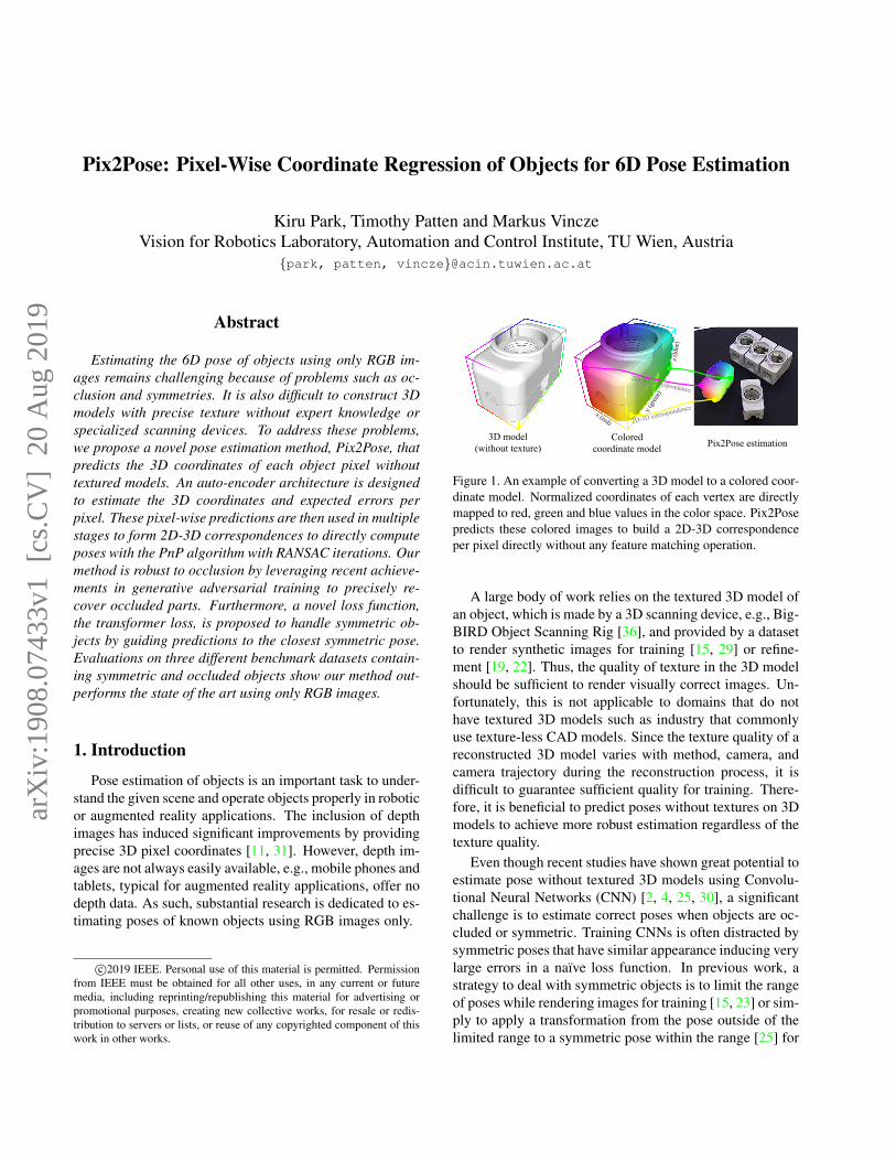
Figure 1. An example of converting a 3D model to a colored coor-dinate model. Normalized coordinates of each vertex are directlymapped to red, green and blue values in the color space. Pix2Posepredicts these colored images to build a 2D-3D correspondenceper pixel directly without any feature matching operation.
A large body of work relies on the textured 3D model ofan object, which is made by a 3D scanning device, e.g., Big-BIRD Object Scanning Rig [36], and provided by a datasetto render synthetic images for training [15, 29] or refine-ment [19, 22]. Thus, the quality of texture in the 3D modelshould be sufficient to render visually correct images. Un-fortunately, this is not applicable to domains that do nothave textured 3D models such as industry that commonlyuse texture-less CAD models. Since the texture quality of areconstructed 3D model varies with method, camera, andcamera trajectory during the reconstruction process, it isdifficult to guarantee sufficient quality for training. There-fore, it is beneficial to predict poses without textures on 3Dmodels to achieve more robust estimation regardless of thetexture quality.
Even though recent studies have shown great potential toestimate pose without textured 3D models using Convolu-tional Neural Networks (CNN) [2, 4, 25, 30], a significantchallenge is to estimate correct poses when objects are oc-cluded or symmetric. Training CNNs is often distracted bysymmetric poses that have similar appearance inducing verylarge errors in a naıve loss function. In previous work, astrategy to deal with symmetric objects is to limit the rangeof poses while rendering images for training [15, 23] or sim-ply to apply a transformation from the pose outside of thelimited range to a symmetric pose within the range [25] for
arX
iv:1
908.
0743
3v1
[cs
.CV
] 2
0 A
ug 2
019
real images with pose annotations. This approach is suffi-cient for objects that have infinite and continuous symmetricposes on a single axis, such as cylinders, by simply ignor-ing the rotation about the axis. However, as pointed in [25],when an object has a finite number of symmetric poses, it isdifficult to determine poses around the boundaries of viewlimits. For example, if a box has an angle of symmetry, π,with respect to an axis and a view limit between 0 and π,the pose at π + α(α ≈ 0, α > 0) has to be transformedto a symmetric pose at α even if the detailed appearance iscloser to a pose at π. Thus, a loss function has to be inves-tigated to guide pose estimations to the closest symmetricpose instead of explicitly defined view ranges.
This paper proposes a novel method, Pix2Pose, that cansupplement any 2D detection pipeline for additional poseestimation. Pix2Pose predicts pixel-wise 3D coordinates ofan object using RGB images without textured 3D modelsfor training. The 3D coordinates of occluded pixels are im-plicitly estimated by the network in order to be robust to oc-clusion. A specialized loss function, the transformer loss,is proposed to robustly train the network with symmetricobjects. As a result of the prediction, each pixel forms a2D-3D correspondence that is used to compute poses by thePerspective-n-Point algorithm (PnP) [18].
To summarize, the contributions of the paper are: (1) Anovel framework for 6D pose estimation, Pix2Pose, that ro-bustly regresses pixel-wise 3D coordinates of objects fromRGB images using 3D models without textures during train-ing. (2) A novel loss function, the transformer loss, for han-dling symmetric objects that have a finite number of am-biguous views. (3) Experimental results on three differentdatasets, LineMOD [9], LineMOD Occlusion [1], and T-Less [10], showing that Pix2Pose outperforms the state-of-the-art methods even if objects are occluded or symmetric.
The remainder of this paper is organized as follows. Abrief summary of related work is provided in Sec. 2. Detailsof Pix2Pose and the pose prediction process are explainedin Sec. 3 and Sec. 4. Experimental results are reported inSec. 5 to compare our approach with the state-of-the-artmethods. The paper concludes in Sec. 6.
2. Related work
This section gives a brief summary of previous work re-lated to pose estimation using RGB images. Three differentapproaches for pose estimation using CNNs are discussedand the recent advances of generative models are reviewed.
CNN based pose estimation The first, and simplest,method to estimate the pose of an object using a CNN isto predict a representation of a pose directly such as the lo-cations of projected points of 3D bounding boxes [25, 30],classified view points [15], unit quaternions and transla-tions [33], or the Lie algebra representation, so(3), with the
translation of z-axis [4]. Except for methods that predictprojected points of the 3D bounding box, which requiresfurther computations for the PnP algorithm, the direct re-gression is computationally efficient since it does not re-quire additional computation for the pose. The drawback ofthese methods, however, is the lack of correspondences thatcan be useful to generate multiple pose hypotheses for therobust estimation of occluded objects. Furthermore, sym-metric objects are usually handled by limiting the rangeof viewpoints, which sometimes requires additional treat-ments, e.g., training a CNN for classifying view ranges [25].Xiang et al. [33] propose a loss function that computes theaverage distance to the nearest points of transformed mod-els in an estimated pose and an annotated pose. However,searching for the nearest 3D points is time consuming andmakes the training process inefficient.
The second method is to match features to find the near-est pose template and use the pose information of the tem-plate as an initial guess [9]. Recently, Sundermeyer etal. [29] propose an auto-encoder network to train implicitrepresentations of poses without supervision using RGBimages only. Manual handling of symmetric objects is notnecessary for this work since the implicit representationcan be close to any symmetric view. However, it is diffi-cult to specify 3D translations using rendered templates thatonly give a good estimation of rotations. The size of the2D bounding box is used to compute the z-component of3D translation, which is too sensitive to small errors of 2Dbounding boxes that are given from a 2D detection method.
The last method is to predict 3D locations of pixels orlocal shapes in the object space [2, 16, 23]. Brachmann etal. [2] regress 3D coordinates and predict a class for eachpixel using the auto-context random forest. Oberwerger etal. [23] predict multiple heat-maps to localize the 2D pro-jections of 3D points of objects using local patches. Thesemethods are robust to occlusion because they focus on lo-cal information only. However, additional computation isrequired to derive the best result among pose hypotheses,which makes these methods slow.
The method proposed in this paper belongs to the lastcategory that predicts 3D locations of pixels in the objectframe as in [1, 2]. Instead of detecting an object using localpatches from sliding windows, an independent 2D detectionnetwork is employed to provide areas of interest for targetobjects as performed in [29].
Generative models Generative models using auto-encoders have been used to de-noise [32] or recover themissing parts of images [34]. Recently, using GenerativeAdversarial Network (GAN) [6] improves the quality ofgenerated images that are less blurry and more realistic,which are used for the image-to-image translation [14], im-age in-painting and de-noising [12, 24] tasks. Zakharov etal. [35] propose a GAN based framework to convert a real
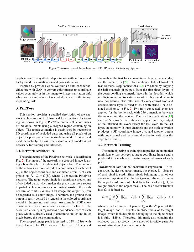
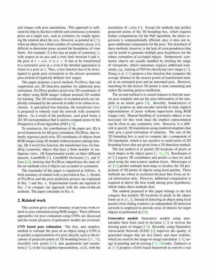
Figure 2. An overview of the architecture of Pix2Pose and the training pipeline.
depth image to a synthetic depth image without noise andbackground for classification and pose estimation.
Inspired by previous work, we train an auto-encoder ar-chitecture with GAN to convert color images to coordinatevalues accurately as in the image-to-image translation taskwhile recovering values of occluded parts as in the imagein-painting task.
3. Pix2PoseThis section provides a detailed description of the net-
work architecture of Pix2Pose and loss functions for train-ing. As shown in Fig. 2, Pix2Pose predicts 3D coordinatesof individual pixels using a cropped region containing anobject. The robust estimation is established by recovering3D coordinates of occluded parts and using all pixels of anobject for pose prediction. A single network is trained andused for each object class. The texture of a 3D model is notnecessary for training and inference.
3.1. Network Architecture
The architecture of the Pix2Pose network is described inFig. 2. The input of the network is a cropped image Is us-ing a bounding box of a detected object class. The outputsof the network are normalized 3D coordinates of each pixelI3D in the object coordinate and estimated errors Ie of eachprediction, I3D, Ie = G(Is), where G denotes the Pix2Posenetwork. The target output includes coordinate predictionsof occluded parts, which makes the prediction more robustto partial occlusion. Since a coordinate consists of three val-ues similar to RGB values in an image, the output I3D canbe regarded as a color image. Therefore, the ground truthoutput is easily derived by rendering the colored coordinatemodel in the ground truth pose. An example of 3D coor-dinate values in a color image is visualized in Fig. 1. Theerror prediction Ie is regarded as a confidence score of eachpixel, which is directly used to determine outlier and inlierpixels before the pose computation.
The cropped image patch is resized to 128×128px withthree channels for RGB values. The sizes of filters and
channels in the first four convolutional layers, the encoder,are the same as in [29]. To maintain details of low-levelfeature maps, skip connections [28] are added by copyingthe half channels of outputs from the first three layers tothe corresponding symmetric layers in the decoder, whichresults in more precise estimation of pixels around geomet-rical boundaries. The filter size of every convolution anddeconvolution layer is fixed to 5×5 with stride 1 or 2 de-noted as s1 or s2 in Fig. 2. Two fully connected layers areapplied for the bottle neck with 256 dimensions betweenthe encoder and the decoder. The batch normalization [13]and the LeakyReLU activation are applied to every outputof the intermediate layers except the last layer. In the lastlayer, an output with three channels and the tanh activationproduces a 3D coordinate image I3D, and another outputwith one channel and the sigmoid activation estimates theexpected errors Ie.
3.2. Network Training
The main objective of training is to predict an output thatminimizes errors between a target coordinate image and apredicted image while estimating expected errors of eachpixel.Transformer loss for 3D coordinate regression To re-construct the desired target image, the average L1 distanceof each pixel is used. Since pixels belonging to an objectare more important than the background, the errors underthe object mask are multiplied by a factor of β (≥ 1) toweight errors in the object mask. The basic reconstructionloss Lr is defined as,
Lr =1
n
[β∑i∈M||Ii3D − Iigt||1 +
∑i/∈M
||Ii3D − Iigt||1], (1)
where n is the number of pixels, Iigt is the ith pixel of thetarget image, and M denotes an object mask of the targetimage, which includes pixels belonging to the object whenit is fully visible. Therefore, this mask also contains theoccluded parts to predict the values of invisible parts forrobust estimation of occluded objects.
Figure 3. An example of the pose estimation process. An image and 2D detection results are the input. In the first stage, the predictedresults are used to specify important pixels and adjust bounding boxes while removing backgrounds and uncertain pixels. In the secondstage, pixels with valid coordinate values and small error predictions are used to estimate poses using the PnP algorithm with RANSAC.Green and blue lines in the result represent 3D bounding boxes of objects in ground truth poses and estimated poses.
The loss above cannot handle symmetric objects since itpenalizes pixels that have larger distances in the 3D spacewithout any knowledge of the symmetry. Having the advan-tage of predicting pixel-wise coordinates, the 3D coordinateof each pixel is easily transformed to a symmetric pose bymultiplying a 3D transformation matrix to the target imagedirectly. Hence, the loss can be calculated for a pose thathas the smallest error among symmetric pose candidates asformulated by,
L3D = minp∈sym
Lr(I3D, RpIgt), (2)
where Rp ∈ R3x3 is a transformation from a pose to a sym-metric pose in a pool of symmetric poses, sym, includingan identity matrix for the given pose. The pool sym is as-sumed to be defined before the training of an object. Thisnovel loss, the transformer loss, is applicable to any sym-metric object that has a finite number of symmetric poses.This loss adds only a tiny effort for computation since asmall number of matrix multiplications is required. Thetransformer loss in Eq. 2 is applied instead of the basic re-construction loss in Eq. 1. The benefit of the transformerloss is analyzed in Sec. 5.7.
Loss for error prediction The error prediction Ie esti-mates the difference between the predicted image I3D andthe target image Igt. This is identical to the reconstructionloss Lr with β = 1 such that pixels under the object maskare not penalized. Thus, the error prediction loss Le is writ-ten as,
Le =1
n
∑i
||Iie −min[Lir , 1
]||22, β = 1. (3)
The error is bounded to the maximum value of the sigmoidfunction.
Traininig with GAN As discussed in Sec. 2, the net-work training with GAN generates more precise and real-istic images in a target domain using images of another do-main [14]. The task for Pix2Pose is similar to this task sinceit converts a color image to a 3D coordinate image of anobject. Therefore, the discriminator and the loss functionof GAN [6], LGAN, is employed to train the network. Asshown in Fig. 2, the discriminator network attempts to dis-tinguish whether the 3D coordinate image is rendered by a3D model or is estimated. The loss is defined as,
LGAN = logD(Igt) + log(1−D(G(Isrc))), (4)
where D denotes the discriminator network. Finally, theobjective of the training with GAN is formulated as,
G∗ = argminG
maxDLGAN(G,D) + λ1L3D(G) + λ2Le(G),
(5)where λ1 and λ2 denote weights to balance different tasks.
4. Pose prediction
This section gives a description of the process that com-putes a pose using the output of the Pix2Pose network. Theoverview of the process is shown in Fig. 3. Before the esti-mation, the center, width, and height of each bounding boxare used to crop the region of interest and resize it to theinput size, 128×128px. The width and height of the regionare set to the same size to keep the aspect ratio by takingthe larger value. Then, they are multiplied by a factor of1.5 so that the cropped region potentially includes occludedparts. The pose prediction is performed in two stages andthe identical network is used in both stages. The first stagealigns the input bounding box to the center of the objectwhich could be shifted due to different 2D detection meth-ods. It also removes unnecessary pixels (background and
uncertain) that are not preferred by the network. The sec-ond stage predicts a final estimation using the refined inputfrom the first stage and computes the final pose.
Stage 1: Mask prediction and Bbox Adjustment In thisstage, the predicted coordinate image I3D is used for speci-fying pixels that belong to the object including the occludedparts by taking pixels with non-zero values. The error pre-diction is used to remove the uncertain pixels if an errorfor a pixel is larger than the outlier threshold θo. The validobject mask is computed by taking the union of pixels thathave non-zero values and pixels that have lower errors thanθo. The new center of the bounding box is determined withthe centroid of the valid mask. As a result, the output of thefirst stage is a refined input that only contains pixels in thevalid mask cropped from a new bounding box. Examplesof outputs of the first stage are shown in Fig. 3. The refinedinput possibly contains the occluded parts when the errorprediction is below the outlier threshold θo, which meansthe coordinates of these pixels are easy to predict despiteocclusions.
Stage 2: Pixel-wise 3D coordinate regression with errorsThe second estimation with the network is performed topredict a coordinate image and expected error values us-ing the refined input as depicted in Fig. 3. Black pixels inthe 3D coordinate samples denote points that are removedwhen the error prediction is larger than the inlier thresh-old θi even though points have non-zero coordinate values.In other words, pixels that have non-zero coordinate valueswith smaller error predictions than θi are used to build 2D-3D correspondences. Since each pixel already has a valuefor a 3D point in the object coordinate, the 2D image coordi-nates and predicted 3D coordinates directly form correspon-dences. Then, applying the PnP algorithm [18] with RAN-dom SAmple Consensus (RANSAC) [5] iteration computesthe final pose by maximizing the number of inliers that havelower re-projection errors than a threshold θre. It is worthmentioning that there is no rendering involved during thepose estimation since Pix2Pose does not assume textured3D models. This also makes the estimation process fast.
5. EvaluationIn this section, experiments on three different datasets
are performed to compare the performance of Pix2Poseto state-of-the-art methods. The evaluation usingLineMOD [9] shows the performance for objects withoutocclusion in the single object scenario. For the multiple ob-ject scenario with occlusions, LineMOD Occlusion [1] andT-Less [10] are used. The evaluation on T-Less shows themost significant benefit of Pix2Pose since T-Less providestexture-less CAD models and most of the objects are sym-metric, which is more challenging and common in industrialdomains.
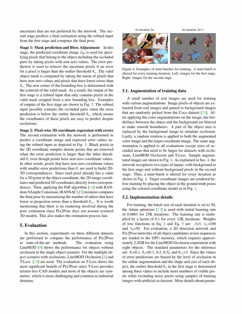
Figure 4. Examples of mini-batches for training. A mini-batch isaltered for every training iteration. Left: images for the first stage,Right: images for the second stage.
5.1. Augmentation of training data
A small number of real images are used for trainingwith various augmentations. Image pixels of objects are ex-tracted from real images and pasted to background imagesthat are randomly picked from the Coco dataset [21]. Af-ter applying the color augmentations on the image, the bor-derlines between the object and the background are blurredto make smooth boundaries. A part of the object area isreplaced by the background image to simulate occlusion.Lastly, a random rotation is applied to both the augmentedcolor image and the target coordinate image. The same aug-mentation is applied to all evaluations except sizes of oc-cluded areas that need to be larger for datasets with occlu-sions, LineMOD Occlusion and T-Less. Sample augmen-tated images are shown in Fig. 4. As explained in Sec. 4, thenetwork recognizes two types of inputs, with background inthe first stage and without background pixels in the secondstage. Thus, a mini-batch is altered for every iteration asshown in Fig. 4. Target coordinate images are rendered be-fore training by placing the object in the ground truth posesusing the colored coordinate model as in Fig. 1.
5.2. Implementation details
For training, the batch size of each iteration is set to 50,the Adam optimizer [17] is used with initial learning rateof 0.0001 for 25K iterations. The learning rate is multi-plied by a factor of 0.1 for every 12K iterations. Weightsof loss functions in Eq. 1 and Eq. 5 are: β=3, λ1=100and λ2=50. For evaluation, a 2D detection network andPix2Pose networks of all object candidates in test sequencesare loaded to the GPU memory, which requires approxi-mately 2.2GB for the LineMOD Occlusion experiment witheight objects. The standard parameters for the inferenceare: θi=0.1, θo=[0.1, 0.2, 0.3], and θre=3. Since the valuesof error predictions are biased by the level of occlusion inthe online augmentation and the shape and size of each ob-ject, the outlier threshold θo in the first stage is determinedamong three values to include more numbers of visible pix-els while excluding noisy pixels using samples of trainingimages with artificial occlusions. More details about param-
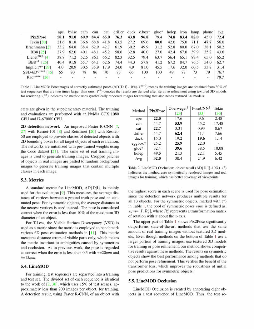
ape bvise cam can cat driller duck e.box* glue* holep iron lamp phone avgPix2Pose 58.1 91.0 60.9 84.4 65.0 76.3 43.8 96.8 79.4 74.8 83.4 82.0 45.0 72.4Tekin [30] 21.6 81.8 36.6 68.8 41.8 63.5 27.2 69.6 80.0 42.6 75.0 71.1 47.7 56.0
Brachmann [2] 33.2 64.8 38.4 62.9 42.7 61.9 30.2 49.9 31.2 52.8 80.0 67.0 38.1 50.2BB8 [25] 27.9 62.0 40.1 48.1 45.2 58.6 32.8 40.0 27.0 42.4 67.0 39.9 35.2 43.6
Lienet30% [4] 38.8 71.2 52.5 86.1 66.2 82.3 32.5 79.4 63.7 56.4 65.1 89.4 65.0 65.2BB8ref [25] 40.4 91.8 55.7 64.1 62.6 74.4 44.3 57.8 41.2 67.2 84.7 76.5 54.0 62.7
Implicitsyn [29] 4.0 20.9 30.5 35.9 17.9 24.0 4.9 81.0 45.5 17.6 32.0 60.5 33.8 31.4SSD-6Dsyn/ref [15] 65 80 78 86 70 73 66 100 100 49 78 73 79 76.7
Radsyn/ref [26] - - - - - - - - - - - - - 78.7
Table 1. LineMOD: Percentages of correctly estimated poses (AD{D|I}-10%). (30%) means the training images are obtained from 30% oftest sequences that are two times larger than ours. (ref) denotes the results are derived after iterative refinement using textured 3D modelsfor rendering. (syn) indicates the method uses synthetically rendered images for training that also needs textured 3D models.
eters are given in the supplementary material. The trainingand evaluations are performed with an Nvidia GTX 1080GPU and i7-6700K CPU.
2D detection network An improved Faster R-CNN [7,27] with Resnet-101 [8] and Retinanet [20] with Resnet-50 are employed to provide classes of detected objects with2D bounding boxes for all target objects of each evaluation.The networks are initialized with pre-trained weights usingthe Coco dataset [21]. The same set of real training im-ages is used to generate training images. Cropped patchesof objects in real images are pasted to random backgroundimages to generate training images that contain multipleclasses in each image.
5.3. Metrics
A standard metric for LineMOD, AD{D|I}, is mainlyused for the evaluation [9]. This measures the average dis-tance of vertices between a ground truth pose and an esti-mated pose. For symmetric objects, the average distance tothe nearest vertices is used instead. The pose is consideredcorrect when the error is less than 10% of the maximum 3Ddiameter of an object.
For T-Less, the Visible Surface Discrepancy (VSD) isused as a metric since the metric is employed to benchmarkvarious 6D pose estimation methods in [11]. This metricmeasures distance errors of visible parts only, which makesthe metric invariant to ambiguities caused by symmetriesand occlusion. As in previous work, the pose is regardedas correct when the error is less than 0.3 with τ=20mm andδ=15mm.
5.4. LineMOD
For training, test sequences are separated into a trainingand test set. The divided set of each sequence is identicalto the work of [2, 30], which uses 15% of test scenes, ap-proximately less than 200 images per object, for training.A detection result, using Faster R-CNN, of an object with
Method Pix2Pose Oberweger†
[23]PoseCNN†
[33]Tekin[30]
ape 22.0 17.6 9.6 2.48can 44.7 53.9 45.2 17.48cat 22.7 3.31 0.93 0.67
driller 44.7 62.4 41.4 7.66duck 15.0 19.2 19.6 1.14
eggbox* 25.2 25.9 22.0 -glue* 32.4 39.6 38.5 10.08holep 49.5 21.3 22.1 5.45Avg 32.0 30.4 24.9 6.42
Table 2. LineMOD Occlusion: object recall (AD{D|I}-10%). (†)indicates the method uses synthetically rendered images and realimages for training, which has better coverage of viewpoints.
the highest score in each scene is used for pose estimationsince the detection network produces multiple results forall 13 objects. For the symmetric objects, marked with (*)in Table 1, the pool of symmetric poses sym is defined as,sym= [I,Rπz ], whereRπz represents a transformation matrixof rotation with π about the z-axis.
The upper part of Table 1 shows Pix2Pose significantlyoutperforms state-of-the-art methods that use the sameamount of real training images without textured 3D mod-els. Even though methods on the bottom of Table 1 use alarger portion of training images, use textured 3D modelsfor training or pose refinement, our method shows competi-tive results against these methods. The results on symmetricobjects show the best performance among methods that donot perform pose refinement. This verifies the benefit of thetransformer loss, which improves the robustness of initialpose predictions for symmetric objects.
5.5. LineMOD Occlusion
LineMOD Occlusion is created by annotating eight ob-jects in a test sequence of LineMOD. Thus, the test se-
Input RGB only RGB-D
Method Pix2Pose Implicit[29]
Kehl[16]
Brachmann[2]
Avg 29.5 18.4 24.6 17.8
Table 3. T-Less: object recall (eVSD < 0.3, τ = 20mm) on all testscenes using PrimeSense. Results of [16] and [2] are cited from[11]. Object-wise results are included in the supplement material.
quences of eight objects in LineMOD are used for train-ing without overlapping with test images. Faster R-CNN isused as a 2D detection pipeline.
As shown in Table 2, Pix2Pose significantly outperformsthe method of [30] using only real images for training. Fur-thermore, Pix2Pose outperforms the state of the art on threeout of eight objects. On average it performs best eventhough methods of [23] and [33] use more images that aresynthetically rendered by using textured 3D models of ob-jects. Although these methods cover more various posesthan the given small number of images, Pix2Pose robustlyestimates poses with less coverage of training poses.
5.6. T-Less
In this dataset, a CAD model without textures and a re-constructed 3D model with textures are given for each ob-ject. Even though previous work uses reconstructed modelsfor training, to show the advantage of our method, CADmodels are used for training (as shown in Fig. 1) with realtraining images provided by the dataset. To minimize thegap of object masks between a real image and a renderedscene using a CAD model, the object mask of the real im-age is used to remove pixels outside of the mask in the ren-dered coordinate images. The pool of symmetric poses symof objects is defined manually similar to the eggbox in theLineMOD evaluation for box-like objects such as obj-05.For cylindrical objects such as obj-01, the rotation com-ponent of the z-axis is simply ignored and regarded as anon-symmetric object. The experiment is performed basedon the protocol of [11]. Instead of a subset of the test se-quences in [11], full test images are used to compare withthe state of the art [29]. Retinanet is used as a 2D detectionmethod and objects visible more than 10% are consideredas estimation targets [11, 29].
The result in Table 3 shows Pix2Pose outperforms the-state-of-the-art method that uses RGB images only by a sig-nificant margin. The performance is also better than the bestlearning-based methods [2, 16] in the benchmark [11]. Al-though these methods use color and depth images to refineposes or to derive the best pose among multiple hypotheses,our method, that predicts a single pose per detected object,performs better than these methods without refinement us-ing depth images.
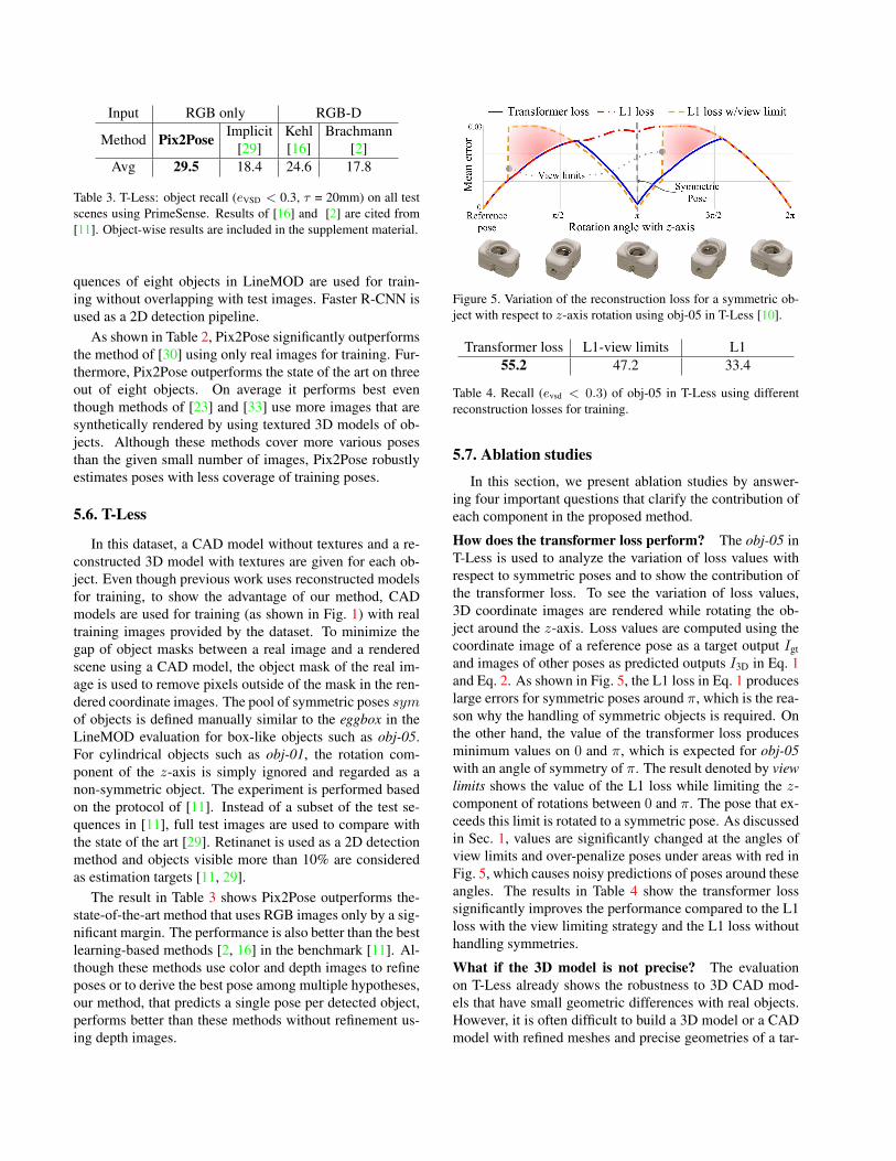
Figure 5. Variation of the reconstruction loss for a symmetric ob-ject with respect to z-axis rotation using obj-05 in T-Less [10].
Transformer loss L1-view limits L155.2 47.2 33.4
Table 4. Recall (evsd < 0.3) of obj-05 in T-Less using differentreconstruction losses for training.
5.7. Ablation studies
In this section, we present ablation studies by answer-ing four important questions that clarify the contribution ofeach component in the proposed method.
How does the transformer loss perform? The obj-05 inT-Less is used to analyze the variation of loss values withrespect to symmetric poses and to show the contribution ofthe transformer loss. To see the variation of loss values,3D coordinate images are rendered while rotating the ob-ject around the z-axis. Loss values are computed using thecoordinate image of a reference pose as a target output Igtand images of other poses as predicted outputs I3D in Eq. 1and Eq. 2. As shown in Fig. 5, the L1 loss in Eq. 1 produceslarge errors for symmetric poses around π, which is the rea-son why the handling of symmetric objects is required. Onthe other hand, the value of the transformer loss producesminimum values on 0 and π, which is expected for obj-05with an angle of symmetry of π. The result denoted by viewlimits shows the value of the L1 loss while limiting the z-component of rotations between 0 and π. The pose that ex-ceeds this limit is rotated to a symmetric pose. As discussedin Sec. 1, values are significantly changed at the angles ofview limits and over-penalize poses under areas with red inFig. 5, which causes noisy predictions of poses around theseangles. The results in Table 4 show the transformer losssignificantly improves the performance compared to the L1loss with the view limiting strategy and the L1 loss withouthandling symmetries.
What if the 3D model is not precise? The evaluationon T-Less already shows the robustness to 3D CAD mod-els that have small geometric differences with real objects.However, it is often difficult to build a 3D model or a CADmodel with refined meshes and precise geometries of a tar-

Figure 6. Top: the fraction of frames within AD{D|I} thresholdsfor the cat in LineMOD. The larger area under a curve means bet-ter performance. Bottom: qualitative results with/without GAN.
get object. Thus, a simpler 3D model, a convex hull cov-ering out-bounds of the object, is used in this experimentas shown in Fig. 6. The training and evaluation are per-formed in the same way for the LineMOD evaluation withsynchronization of object masks using annotated masks ofreal images. As shown in the top-left of Fig. 6, the perfor-mance slightly drops when using the convex hull. However,the performance is still competitive with methods that use3D bounding boxes of objects, which means that Pix2Poseuses the details of 3D coordinates for robust estimation eventhough 3D models are roughly reconstructed.
Does GAN improve results? The network of Pix2Posecan be trained without GAN by removing the GAN loss inthe final loss function in Eq. 5. Thus, the network only at-tempts to reconstruct the target image without trying to trickthe discriminator. To compare the performance, the sametraining procedure is performed without GAN until the lossvalue excluding the GAN loss reaches the same level. Re-sults in the top-left in Fig. 6 shows the fraction of correctlyestimated poses with varied thresholds for the ADD metric.Solid lines show the performance on the original LineMODtest images, which contains fully visible objects, and dashedlines represent the performance on the same test imageswith artificial occlusions that are made by replacing 50%of areas in each bounding box with zero. There is no sig-nificant change in the performance when objects are fullyvisible. However, the performance drops significantly with-out GAN when objects are occluded. Examples in the bot-tom of Fig. 6 also show training with GAN produces robustpredictions on occluded parts.
Is Pix2Pose robust to different 2D detection networks?Table 5 reports the results using different 2D detectionnetworks on LineMOD. Retinanet and Faster R-CNNare trained using the same training images used in the
SSD-6D[15]
Retina[20]
R-CNN[27]
GTbbox
2D bbox 89.1 97.7 98.6 1006D pose 64.0 71.1 72.4 74.7
6D pose/2D bbox 70.9 72.4 73.2 74.7
Table 5. Average percentages of correct 2D bounding boxes(IoU>0.5) and correct 6D poses (ADD-10%) on LineMOD us-ing different 2D detection methods. The last row reports the per-centage of correctly estimated poses on scenes that have correctbounding boxes (IoU>0.5).
LineMOD evaluation. In addition, the public code andtrained weights of SSD-6D [15] are used to derive 2D detec-tion results while ignoring pose predictions of the network.It is obvious that pose estimation results are proportional to2D detection performances. On the other hand, the portionof correct poses on good bounding boxes (those that overlapmore than 50% with ground truth) does not change signif-icantly. This shows that Pix2Pose is robust to different 2Ddetection results when a bounding box overlaps the targetobject sufficiently. This robustness is accomplished by therefinement in the first stage that extracts useful pixels witha re-centered bounding box from a test image. Without thetwo stage approach, the performance significantly drops to41% on LineMOD when the output of the network in thefirst stage is used directly for the PnP computation.
5.8. Inference time
The inference time varies according to the 2D detectionnetworks. Faster R-CNN takes 127ms and Retinanet takes76ms to detect objects from an image with 640×480px.The pose estimation for each bounding box takes approx-imately 25-45ms per region. Thus, our method is able toestimate poses at 8-10 fps with Retinanet and 6-7 fps withFaster R-CNN in the single object scenario.
6. ConclusionThis paper presented a novel architecture, Pix2Pose, for
6D object pose estimation from RGB images. Pix2Pose ad-dresses several practical problems that arise during pose es-timation: the difficulty of generating real-world 3D modelswith high-quality texture as well as robust pose estimationof occluded and symmetric objects. Evaluations with threechallenging benchmark datasets show that Pix2Pose signif-icantly outperforms state-of-the-art methods while solvingthese aforementioned problems.
Our results reveal that many failure cases are related tounseen poses that are not sufficiently covered by trainingimages or the augmentation process. Therefore, future workwill investigate strategies to improve data augmentation tomore broadly cover pose variations using real images in or-der to improve estimation performance. Another avenue for
future work is to generalize the approach to use a single net-work to estimate poses of various objects in a class that havesimilar geometry but different local shape or scale.
Acknowledgment The research leading to these results has re-ceived funding from the Austrian Science Foundation (FWF) un-der grant agreement No. I3967-N30 (BURG) and No. I3969-N30(InDex), and Aelous Robotics, Inc.
References[1] Eric Brachmann, Alexander Krull, Frank Michel, Stefan
Gumhold, Jamie Shotton, and Carsten Rother. Learning 6dobject pose estimation using 3d object coordinates. In TheEuropean Conference on Computer Vision (ECCV), 2014. 2,5
[2] Eric Brachmann, Frank Michel, Alexander Krull, MichaelYing Yang, Stefan Gumhold, and Carsten Rother.Uncertainty-driven 6d pose estimation of objects andscenes from a single rgb image. In The IEEE Conference onComputer Vision and Pattern Recognition (CVPR), 2016. 1,2, 6, 7
[3] G. Bradski. The OpenCV Library. Dr. Dobb’s Journal ofSoftware Tools, 2000. 11
[4] Thanh-Toan Do, Trung Pham, Ming Cai, and Ian Reid.Real-time monocular object instance 6d pose estimation. InBritish Machine Vision Conference (BMVC), 2018. 1, 2, 6
[5] Martin A. Fischler and Robert C. Bolles. Random sampleconsensus: A paradigm for model fitting with applications toimage analysis and automated cartography. Commun. ACM,24(6):381–395, June 1981. 5
[6] Ian Goodfellow, Jean Pouget-Abadie, Mehdi Mirza, BingXu, David Warde-Farley, Sherjil Ozair, Aaron Courville, andYoshua Bengio. Generative adversarial nets. In Advancesin neural information processing systems, pages 2672–2680,2014. 2, 4
[7] Kaiming He, Georgia Gkioxari, Piotr Dollar, and Ross Gir-shick. Mask r-cnn. In The IEEE International Conferenceon Computer Vision (ICCV), 2017. 6
[8] Kaiming He, Xiangyu Zhang, Shaoqing Ren, and Jian Sun.Deep residual learning for image recognition. In The IEEEConference on Computer Vision and Pattern Recognition(CVPR), 2016. 6
[9] Stefan Hinterstoisser, Vincent Lepetit, Slobodan Ilic, Ste-fan Holzer, Gary Bradski, Kurt Konolige, and Nassir Navab.Model based training, detection and pose estimation oftexture-less 3d objects in heavily cluttered scenes. In Asianconference on computer vision (ACCV), 2012. 2, 5, 6
[10] Tomas Hodan, Pavel Haluza, Stepan Obdrzalek, Jirı Matas,Manolis Lourakis, and Xenophon Zabulis. T-LESS: AnRGB-D dataset for 6D pose estimation of texture-less ob-jects. IEEE Winter Conference on Applications of ComputerVision (WACV), 2017. 2, 5, 7
[11] Tomas Hodan, Frank Michel, Eric Brachmann, Wadim Kehl,Anders GlentBuch, Dirk Kraft, Bertram Drost, Joel Vidal,Stephan Ihrke, Xenophon Zabulis, Caner Sahin, Fabian Man-hardt, Federico Tombari, Tae-Kyun Kim, Jiri Matas, and
Carsten Rother. Bop: Benchmark for 6d object pose esti-mation. In The European Conference on Computer Vision(ECCV), 2018. 1, 6, 7, 12
[12] Satoshi Iizuka, Edgar Simo-Serra, and Hiroshi Ishikawa.Globally and locally consistent image completion. ACMTransactions on Graphics (ToG), 36(4):107, 2017. 2
[13] Sergey Ioffe and Christian Szegedy. Batch normalization:Accelerating deep network training by reducing internal co-variate shift. In International Conference on Machine Learn-ing, pages 448–456, 2015. 3
[14] Phillip Isola, Jun-Yan Zhu, Tinghui Zhou, and Alexei A.Efros. Image-to-image translation with conditional adversar-ial networks. In The IEEE Conference on Computer Visionand Pattern Recognition (CVPR), July 2017. 2, 4
[15] Wadim Kehl, Fabian Manhardt, Federico Tombari, Slobo-dan Ilic, and Nassir Navab. Ssd-6d: Making rgb-based 3ddetection and 6d pose estimation great again. In The IEEEInternational Conference on Computer Vision (ICCV), 2017.1, 2, 6, 8
[16] Wadim Kehl, Fausto Milletari, Federico Tombari, SlobodanIlic, and Nassir Navab. Deep learning of local rgb-d patchesfor 3d object detection and 6d pose estimation. In The Eu-ropean Conference on Computer Vision (ECCV), 2016. 2,7
[17] Diederik P Kingma and Jimmy Lei Ba. Adam: A methodfor stochastic optimization. In Proceedings of the 3rd In-ternational Conference on Learning Representations (ICLR),2015. 5
[18] Vincent Lepetit, Francesc Moreno-Noguer, and Pascal Fua.Epnp: An accurate o(n) solution to the pnp problem. Inter-national Journal of Computer Vision, 81(2):155, Jul 2008. 2,5
[19] Yi Li, Gu Wang, Xiangyang Ji, Yu Xiang, and Dieter Fox.Deepim: Deep iterative matching for 6d pose estimation.In The European Conference on Computer Vision (ECCV),2018. 1
[20] Tsung-Yi Lin, Priya Goyal, Ross Girshick, Kaiming He, andPiotr Dollar. Focal loss for dense object detection. In TheIEEE International Conference on Computer Vision (ICCV),2017. 6, 8
[21] Tsung-Yi Lin, Michael Maire, Serge Belongie, James Hays,Pietro Perona, Deva Ramanan, Piotr Dollar, and C LawrenceZitnick. Microsoft coco: Common objects in context. In TheEuropean Conference on Computer Vision (ECCV), 2014. 5,6
[22] Fabian Manhardt, Wadim Kehl, Nassir Navab, and FedericoTombari. Deep model-based 6d pose refinement in rgb.In The European Conference on Computer Vision (ECCV),2018. 1
[23] Markus Oberweger, Mahdi Rad, and Vincent Lepetit. Mak-ing deep heatmaps robust to partial occlusions for 3d objectpose estimation. In The European Conference on ComputerVision (ECCV), 2018. 1, 2, 6, 7
[24] Deepak Pathak, Philipp Krahenbuhl, Jeff Donahue, TrevorDarrell, and Alexei A Efros. Context encoders: Featurelearning by inpainting. In The IEEE Conference on Com-puter Vision and Pattern Recognition (CVPR), 2016. 2
[25] Mahdi Rad and Vincent Lepetit. Bb8: A scalable, accurate,robust to partial occlusion method for predicting the 3d posesof challenging objects without using depth. In The IEEEInternational Conference on Computer Vision (ICCV), 2017.1, 2, 6
[26] Mahdi Rad, Markus Oberweger, and Vincent Lepetit. Fea-ture mapping for learning fast and accurate 3d pose inferencefrom synthetic images. In The IEEE Conference on Com-puter Vision and Pattern Recognition (CVPR), 2018. 6
[27] Shaoqing Ren, Kaiming He, Ross Girshick, and Jian Sun.Faster r-cnn: Towards real-time object detection with regionproposal networks. In Advances in neural information pro-cessing systems, pages 91–99, 2015. 6, 8
[28] Olaf Ronneberger, Philipp Fischer, and Thomas Brox. U-net: Convolutional networks for biomedical image segmen-tation. In International Conference on Medical image com-puting and computer-assisted intervention, pages 234–241.Springer, 2015. 3
[29] Martin Sundermeyer, Zoltan-Csaba Marton, MaximilianDurner, Manuel Brucker, and Rudolph Triebel. Implicit 3dorientation learning for 6d object detection from rgb images.In The European Conference on Computer Vision (ECCV),2018. 1, 2, 3, 6, 7
[30] Bugra Tekin, Sudipta N. Sinha, and Pascal Fua. Real-timeseamless single shot 6d object pose prediction. In The IEEEConference on Computer Vision and Pattern Recognition(CVPR), 2018. 1, 2, 6, 7
[31] Joel Vidal, Chyi-Yeu Lin, and Robert Martı. 6d pose estima-tion using an improved method based on point pair features.In 2018 4th International Conference on Control, Automa-tion and Robotics (ICCAR), pages 405–409, 2018. 1
[32] Pascal Vincent, Hugo Larochelle, Isabelle Lajoie, YoshuaBengio, and Pierre-Antoine Manzagol. Stacked denoisingautoencoders: Learning useful representations in a deep net-work with a local denoising criterion. Journal of machinelearning research, 11(Dec):3371–3408, 2010. 2
[33] Yu Xiang, Tanner Schmidt, Venkatraman Narayanan, andDieter Fox. Posecnn: A convolutional neural network for 6dobject pose estimation in cluttered scenes. Robotics: Scienceand Systems (RSS), 2018. 2, 6, 7
[34] Junyuan Xie, Linli Xu, and Enhong Chen. Image denois-ing and inpainting with deep neural networks. In Advancesin neural information processing systems, pages 341–349,2012. 2
[35] Sergey Zakharov, Benjamin Planche, Ziyan Wu, AndreasHutter, Harald Kosch, and Slobodan Ilic. Keep it unreal:Bridging the realism gap for 2.5 d recognition with geom-etry priors only. In International Conference on 3D Vision(3DV), 2018. 2
[36] Berk alli, Aaron Walsman, Arjun Singh, Siddhartha S. Srini-vasa, Pieter Abbeel, and Aaron M. Dollar. Benchmarking inmanipulation research: Using the yale-cmu-berkeley objectand model set. IEEE Robotics and Automation Magazine,22:36–52, 2015. 1
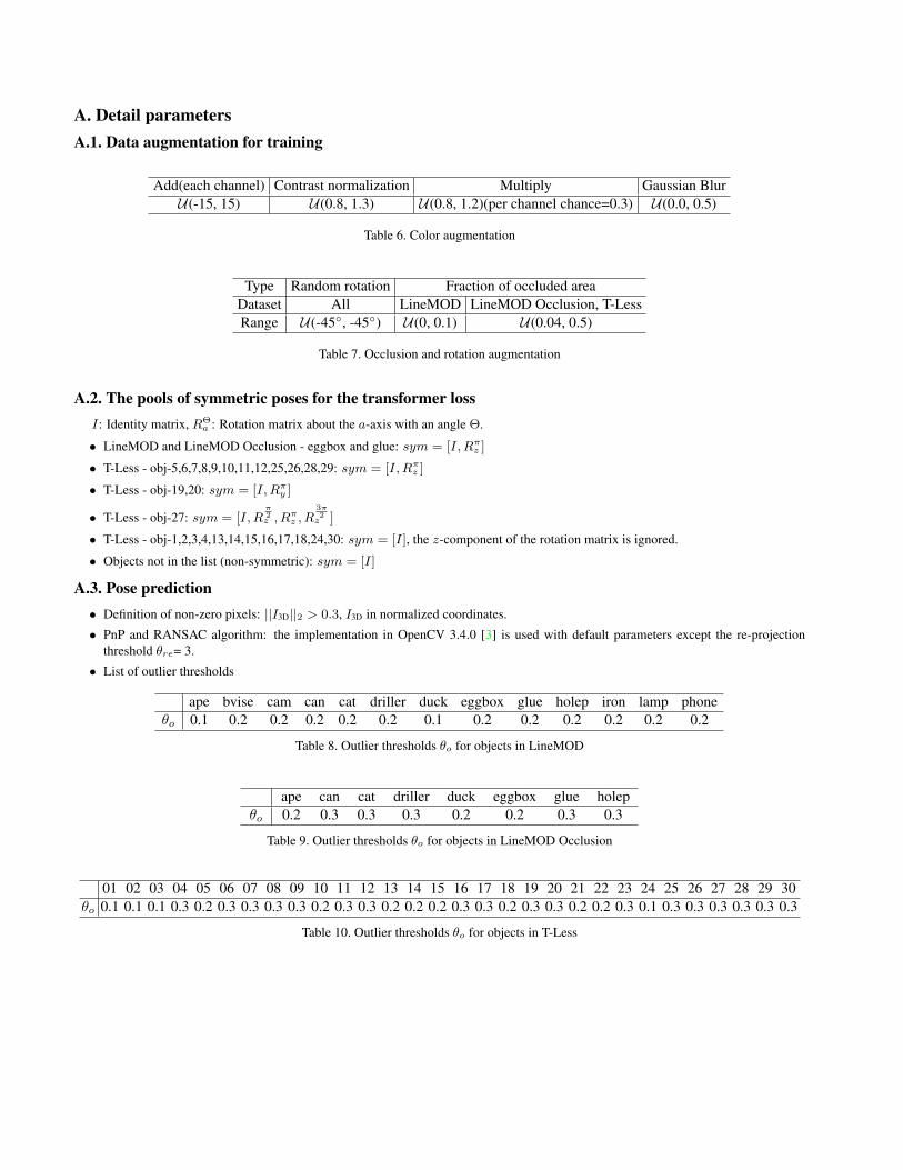
A. Detail parametersA.1. Data augmentation for training
Add(each channel) Contrast normalization Multiply Gaussian BlurU(-15, 15) U(0.8, 1.3) U(0.8, 1.2)(per channel chance=0.3) U(0.0, 0.5)
Table 6. Color augmentation
Type Random rotation Fraction of occluded areaDataset All LineMOD LineMOD Occlusion, T-LessRange U(-45◦, -45◦) U(0, 0.1) U(0.04, 0.5)
Table 7. Occlusion and rotation augmentation
A.2. The pools of symmetric poses for the transformer lossI: Identity matrix, RΘ
a : Rotation matrix about the a-axis with an angle Θ.
• LineMOD and LineMOD Occlusion - eggbox and glue: sym = [I, Rπz ]
• T-Less - obj-5,6,7,8,9,10,11,12,25,26,28,29: sym = [I,Rπz ]
• T-Less - obj-19,20: sym = [I, Rπy ]
• T-Less - obj-27: sym = [I, Rπ2z , R
πz , R
3π2z ]
• T-Less - obj-1,2,3,4,13,14,15,16,17,18,24,30: sym = [I], the z-component of the rotation matrix is ignored.
• Objects not in the list (non-symmetric): sym = [I]
A.3. Pose prediction• Definition of non-zero pixels: ||I3D||2 > 0.3, I3D in normalized coordinates.
• PnP and RANSAC algorithm: the implementation in OpenCV 3.4.0 [3] is used with default parameters except the re-projectionthreshold θre= 3.
• List of outlier thresholds
ape bvise cam can cat driller duck eggbox glue holep iron lamp phoneθo 0.1 0.2 0.2 0.2 0.2 0.2 0.1 0.2 0.2 0.2 0.2 0.2 0.2
Table 8. Outlier thresholds θo for objects in LineMOD
ape can cat driller duck eggbox glue holepθo 0.2 0.3 0.3 0.3 0.2 0.2 0.3 0.3
Table 9. Outlier thresholds θo for objects in LineMOD Occlusion
01 02 03 04 05 06 07 08 09 10 11 12 13 14 15 16 17 18 19 20 21 22 23 24 25 26 27 28 29 30θo 0.1 0.1 0.1 0.3 0.2 0.3 0.3 0.3 0.3 0.2 0.3 0.3 0.2 0.2 0.2 0.3 0.3 0.2 0.3 0.3 0.2 0.2 0.3 0.1 0.3 0.3 0.3 0.3 0.3 0.3
Table 10. Outlier thresholds θo for objects in T-Less
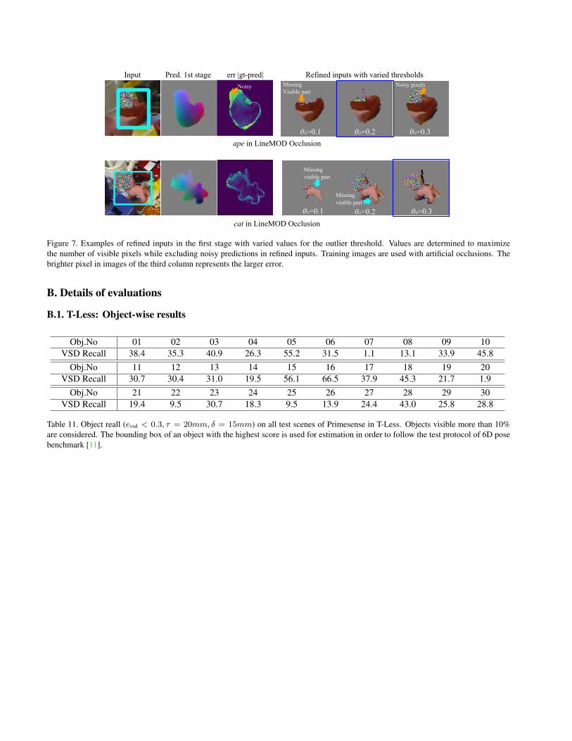
Figure 7. Examples of refined inputs in the first stage with varied values for the outlier threshold. Values are determined to maximizethe number of visible pixels while excluding noisy predictions in refined inputs. Training images are used with artificial occlusions. Thebrighter pixel in images of the third column represents the larger error.
B. Details of evaluations
B.1. T-Less: Object-wise results
Obj.No 01 02 03 04 05 06 07 08 09 10VSD Recall 38.4 35.3 40.9 26.3 55.2 31.5 1.1 13.1 33.9 45.8
Obj.No 11 12 13 14 15 16 17 18 19 20VSD Recall 30.7 30.4 31.0 19.5 56.1 66.5 37.9 45.3 21.7 1.9
Obj.No 21 22 23 24 25 26 27 28 29 30VSD Recall 19.4 9.5 30.7 18.3 9.5 13.9 24.4 43.0 25.8 28.8
Table 11. Object reall (evsd < 0.3, τ = 20mm, δ = 15mm) on all test scenes of Primesense in T-Less. Objects visible more than 10%are considered. The bounding box of an object with the highest score is used for estimation in order to follow the test protocol of 6D posebenchmark [11].
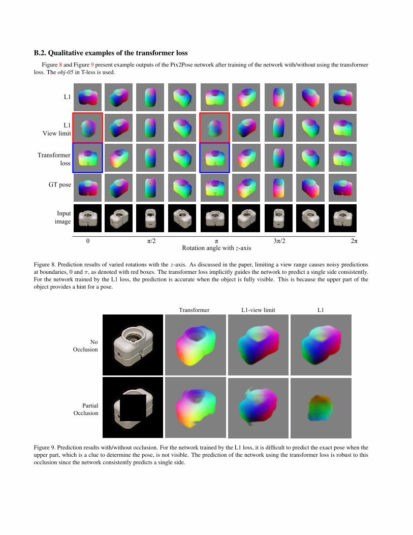
B.2. Qualitative examples of the transformer lossFigure 8 and Figure 9 present example outputs of the Pix2Pose network after training of the network with/without using the transformer
loss. The obj-05 in T-less is used.
Figure 8. Prediction results of varied rotations with the z-axis. As discussed in the paper, limiting a view range causes noisy predictionsat boundaries, 0 and π, as denoted with red boxes. The transformer loss implicitly guides the network to predict a single side consistently.For the network trained by the L1 loss, the prediction is accurate when the object is fully visible. This is because the upper part of theobject provides a hint for a pose.
Figure 9. Prediction results with/without occlusion. For the network trained by the L1 loss, it is difficult to predict the exact pose when theupper part, which is a clue to determine the pose, is not visible. The prediction of the network using the transformer loss is robust to thisocclusion since the network consistently predicts a single side.
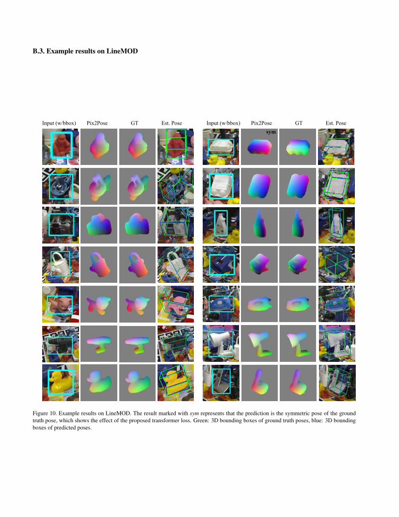
B.3. Example results on LineMOD
Figure 10. Example results on LineMOD. The result marked with sym represents that the prediction is the symmetric pose of the groundtruth pose, which shows the effect of the proposed transformer loss. Green: 3D bounding boxes of ground truth poses, blue: 3D boundingboxes of predicted poses.

B.4. Example results on LineMOD Occlusion
Figure 11. Example results on LineMOD Occlusion. The precise prediction of occluded parts enhances robustness.

B.5. Example results on T-Less
Figure 12. Example results on T-Less. For visualization, ground-truth bounding boxes are used to show pose estimation results regardlessof the 2D detection performance. Results with rot denote estimations of objects with cylindrical shapes.
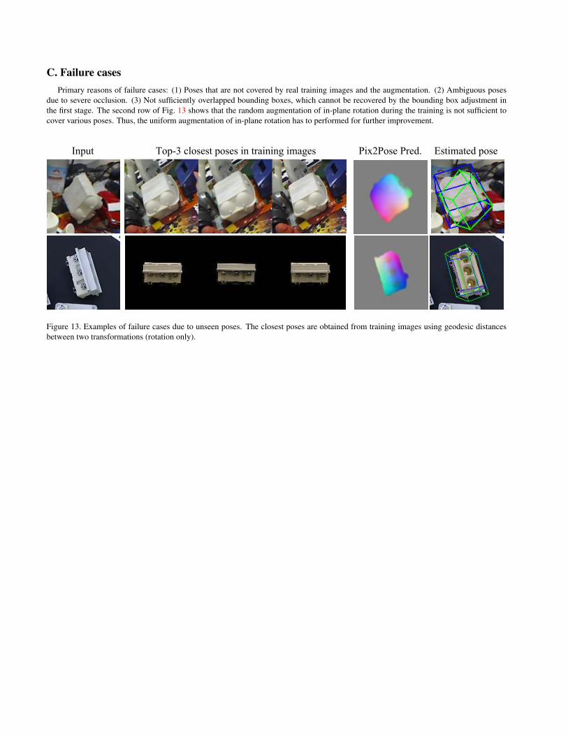
C. Failure casesPrimary reasons of failure cases: (1) Poses that are not covered by real training images and the augmentation. (2) Ambiguous poses
due to severe occlusion. (3) Not sufficiently overlapped bounding boxes, which cannot be recovered by the bounding box adjustment inthe first stage. The second row of Fig. 13 shows that the random augmentation of in-plane rotation during the training is not sufficient tocover various poses. Thus, the uniform augmentation of in-plane rotation has to performed for further improvement.
Figure 13. Examples of failure cases due to unseen poses. The closest poses are obtained from training images using geodesic distancesbetween two transformations (rotation only).