pks603-606 flyer 606 - power
TRANSCRIPT

www.powerint.com June 2006
PeakSwitch™ Family Enhanced, Energy-Efficient, Off-Line SwitcherIC With Super Peak Power Performance
JUNE 2006
PRODUCT HIGHLIGHTS• Simple ON/OFF control – no loop compensation
needed• Delivers peak power of up to 3 times maximum
continuous output power• 277 kHz operation during peak power significantly
reduces transformer size• Tight I2f tolerances and negligible temperature variation
of key parameters ease design and lower cost• Adaptive switching cycle on-time extension in-
creases low line peak output power, minimizing bulk capacitor size
• High bandwidth provides fast turn on with no overshoot and excellent transient load response
HIGH PERFORMANCE AT LOW COST
• Ideal for large peak to continuous load ratio requirements (up to 3 × P
OUT(CONT.))
• Programmable smart AC line sensing provides latching shutdown during short circuit, overload and open loop faults
• Adaptive current limit reduces output overload power • Accurate hysteretic thermal shutdown with auto-
matic recovery provides complete system level over- load protection and eliminates need for manual reset
• Very low component count – higher reliability and single side printed circuit board
• Frequency jittering reduces EMI filter cost
EcoSmart® - EXTREMELY ENERGY EFFICIENT
• Surpasses California Energy Commission (CEC), ENERGY STAR, and EU requirements• No-load consumption <200 mW at 265 VAC input• Standby output power ≥0.6 W for 1 W input power • Sleep mode power ≥2.4 W at 3 W input
FEATURES & BENEFITS
See Data Sheet for Additional Notes and Conditions.
OUTPUT POWER TABLE
PRODUCT230 VAC ±15% 85-265 VAC
Adapter Cont.
Adapter Peak
Adapter Cont.
Adapter Peak
PKS603 P 13 W 32 W 9 W 25 W
PKS604 P 23 W 56 W 16 W 44 W
PKS604 Y/F 35 W 56 W 23 W 44 W
PKS605 P 31 W 60 W 21 W 44 W
PKS605 Y/F 46 W 79 W 30 W 58 W
PKS606 P 35 W 66 W 25 W 46 W
PKS606 Y/F 68 W 117 W 45 W 86 W
Typical Applications: Inkjet Printer, Data Storage,Audio Amplifier, DC Motor Drives
P = DIP-8
TYPICAL PEAK POWER APPLICATION
D
S
ACIN
DCOUT
Optional SmartAC Sense
+
PeakSwitch
PI-3995-051006
EN/UV
BP
Y = TO-220 F = TO-262

www.powerint.com
PeakSwitch™ Family Design Tools
* Downloadable from www.powerint.com
PeakSwitch PRODUCT & DESIGN COLLATERAL*Data Sheet PKS603-606 PeakSwitch Family Data Sheet
Application Note AN-41 PeakSwitch Design Guide
Engineering Report EPR-93 Application: 32 W Continuous, 81 W Peak Power Supply Using PKS606Y (90-265 VAC Input, 30 V, 1.07 A Continuous, 2.7 A Peak Output)
Design Idea DI-93 Application: 32 W Continuous, 81 W Peak Power Supply Using PKS606Y (90-265 VAC Input, 30 V, 1.07 A Continuous, 2.7 A Peak Output)
POWER SUPPLY DESIGN SOFTWARE
DAK-93: 32 W Continuous, 81 W Peak Power Supply
With PI Expert™ Suite, you’re only minutes away from determining the key components in your next power supply, including transformer design. It’s fast, easy and FREE! Order a CD or download the software at:
FAST APPLICATION CUSTOMER TECHNICAL SUPPORT
Find relevant design information FAST!
PI FACTS identifi es and displays the product information and reference designs that match your application specs. Try it now at:
REFERENCE DESIGN (DAK-93)
DAKs include a reference design power supply, sample devices, unpopulated pcb, data sheet, comprehensive engineering report and other related documentation. Get more information at:
www.powerint.com/facts
www.powerint.com/dak.htm www.powerint.com/designsoftware.htm
www.powerint.com
Design Idea DI-93
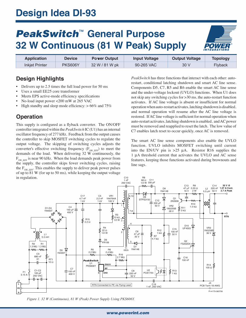
Application Device Power Output Input Voltage Output Voltage TopologyInkjet Printer PKS606Y 32 W / 81 W pk 90-265 VAC 30 V Flyback
PeakSwitch has three functions that interact with each other: auto-restart, conditional latching shutdown and smart AC line sense. Components D5, C7, R5 and R6 enable the smart AC line sense and the under-voltage lockout (UVLO) functions. When U1 does not skip any switching cycles for >30 ms, the auto-restart function activates. If AC line voltage is absent or insufficient for normal operation when auto-restart activates, latching shutdown is disabled, and normal operation will resume after the AC line voltage is restored. If AC line voltage is sufficient for normal operation when auto-restart activates, latching shutdown is enabled, and AC power must be removed and reapplied to reset the latch. The low value of C7 enables latch reset to occur quickly, once AC is removed.
The smart AC line sense components also enable the UVLO function. UVLO inhibits MOSFET switching until current into the EN/UV pin is >25 µA. Resistor R16 supplies the 1 µA threshold current that activates the UVLO and AC sense features, keeping those functions activated during brownouts and line sags.
Figure 1. 32 W (Continuous), 81 W (Peak) Power Supply Using PKS606Y.
Design Highlights• Delivers up to 2.5 times the full load power for 50 ms• Uses a small EE25 core transformer• Meets EPS active-mode efficiency specifications• No-load input power <200 mW at 265 VAC• High standby and sleep mode efficiency: > 66% and 75%
OperationThis supply is configured as a flyback converter. The ON/OFF controller integrated within the PeakSwitch IC (U1) has an internal oscillator frequency of 277 kHz. Feedback from the output causes the controller to skip MOSFET switching cycles to regulate the output voltage. The skipping of switching cycles adjusts the converter s effective switching frequency (FSW_EFF) to meet the demands of the load. When delivering 32 W continuously, the FSW_EFF is near 90 kHz. When the load demands peak power from the supply, the controller skips fewer switching cycles, raising the FSW_EFF. This enables the supply to deliver peak power pulses of up to 81 W (for up to 50 ms), while keeping the output voltage in regulation.
PeakSwitch™ General Purpose 32 W Continuous (81 W Peak) Supply
T1EE25
J1L
PE
N
30 V @1.07 A Cont.2.7 A Peak
RTN
D51N4007
D6FR106
D10UF4003
D8STPS3150
D91N4148
D71N4148
U2PC817X4
Q2FS202DA
J3PCB Term 18 AWGRTN Connected to PE via Flying Lead
Q12N3906
D1-D41N4007
L15.3 mH
L25.3 µH
R21.3 MΩ
R11.3 MΩ
R152.2 Ω
R422 Ω1/2 W
R310 kΩ1/2 W
R52.2 MΩ
R62.4 MΩ
R162.7 MΩ
R74.7 kΩ
R121 kΩ
R131 kΩ
R14100 Ω
R113 kΩ
R101.5 kΩ
R90.33 Ω
2 W
R868 Ω1/2 W
C3680 nF
X1
C1-C2100 pF
250 VAC
C174.7 nF1 kV
C647 µF35 V
C15100 nF50 V
C16100 nF
C12330 µF50 V
C101 nF
250 VACC11
330 pF
U1PKS606Y
C1347 µF16 V
C14220 nF50 V
C7100 nF400 V
C8220 nF50 V
C52.2 nF1 kV
VR11N4764A
100 V
VR21N5255B
28 V
VR31N5258B
36 V
1
9,10
7,8
4
5
3
2
C4150 µF400 V
F13.15 A
RT110 Ω
PI-4170-060706
tO
PeakSwitch
C191 nF, 250 VAC
D
S
EN/UV
BP
GND

www.powerint.com
DI-93
Figure 2. Active-Mode Efficiency Performance.
Figure 3. Available Output Power at 1 W and 3 W Input Power.Figure 4. Conducted EMI to EN55022 B Limit, at Full Load, with 115 VAC, 60 Hz Input Voltage.
Power Integrations reserves the right to make changes to its products at any time to improve reliability or manufacturability. Power Integrations does not assume any liability arising from the use of any device or circuit described herein. POWER INTEGRATIONS MAKES NO WARRANTY HEREIN AND SPECIFICALLY DISCLAIMS ALL WARRANTIES INCLUDING, WITHOUT LIMITATIONS, THE IMPLIED WARRANTIES OF MERCHANTABILITY, FITNESS FOR A PARTICULAR PURPOSE, AND NON-INFRINGEMENT OF THIRD PARTY RIGHTS. The products and applications illustrated herein (transformer construction and circuits external to the products) may be covered by one or more U.S. and foreign patents or potentially by pending U.S. and foreign patent applications assigned to Power Integrations. A complete list of Power Integrations' patents may be found at www.powerint.com. Power Integrations grants its customers a license under certain patent rights as set forth at http://www.powerint.com/ip.htm. The PI logo, TOPSwitch, TinySwitch, LinkSwitch, DPA-Switch, PeakSwitch, EcoSmart, Clampless, E-Shield, Filterfuse, PI Expert and PI FACTS are trademarks of Power Integrations, Inc. Other trademarks are property of their respective companies. Copyright 2006, Power Integrations, Inc.
POWER INTEGRATIONS WORLDWIDE SALES SUPPORT LOCATIONS
APPLICATIONS HOTLINEPhone: +1 408-414-9660Fax: +1 408-414-9760
CHINA (SHANGHAI)Shanghai, China Phone: +86-21-6215-5548E-mail: [email protected]
INDIABangalore, IndiaPhone: +91-80-5113-8020E-mail: [email protected]
KOREASeoul, KoreaPhone: +82-2-2016-6610E-mail: [email protected]
EUROPE HQFarnham, Surrey, United KingdomPhone: +44 (0) 1252-730-140E-mail: [email protected]
CUSTOMER SERVICEPhone: +1 408-414-9665Fax: +1 408-414-9765
CHINA (SHENZHEN)Shenzhen, China Phone: +86-755-8379-3243E-mail: [email protected]
ITALYMilano, ItalyPhone: +39-028-928-6000E-mail: [email protected]
SINGAPORESingapore Phone: +65-6358-2160E-mail: [email protected]
WORLD HEADQUARTERSSan Jose, CA, USAPhone: +1 408-414-9200E-mail: [email protected]
GERMANYMunich, Germany Phone: +49-89-5527-3910E-mail: [email protected]
JAPANKanagawa, JapanPhone: +81-45-471-1021E-mail: [email protected]
TAIWANTaipei, TaiwanPhone: +886-2-2659-4570E-mail: [email protected]
For a complete list of our Worldwide Sales Representatives & Distributors visit our Web site: www.powerint.com
For the latest updates, visit www.powerint.com
Ten components enable load overvoltage and over-current protection: C13, C16, D10, Q1, Q2, R9, R10, R11, R14 and VR3. They work with the latching shutdown function as follows:
– If the supply output voltage goes above 36 V, VR3 conducts and turns on Q2, which shorts the secondary winding of T1. After 30 ms of U1 receiving no feedback, the supply latches off.
– If the load pulls peak current for longer than the RC time constant (≈ 60 ms) of C13 and R10, Q1 turns on, which turns Q2 on and shorts the secondary winding of T1. Again, after 30 ms of U1 receiving no feedback, the supply latches off.
Capacitor C17 attenuates differential-mode conducted EMI. Resistor R15 dampens high frequency ringing.
Key Design Points• The value of C7 sets the reset time of the latched shutdown
function, once the AC input is removed. Verify that the latch resets, within the time allowed, at the highest input voltage.
• For thermal considerations, the PeakSwitch IC, the output diode and their heatsinks, and the transformer core size depend on the continuous-to-peak power ratio, and the duration and frequency of the peak power pulses.
• Choose the values for R10 and C13 so that normal peak loads will not turn Q1 on. However, do not set the RC time constant so long that the supply does not latch off within the 60 seconds specified by IEC 60950-1, section 2.5, Table 2B (Limited Power Sources requirements).
20
10
0
1050 15 20 25 30 35
Output Power (W)
Eff
icie
ncy
(%
)
40
30
70
80
90
60
50
115 VAC Input230 VAC Input
PI-
4311
-021
506
.75
.50
.25
.00
140100 12080 160 180 200 220 240 260 280
AC Input Voltage
Ava
ilab
le O
utp
ut
Po
wer
(W
)
1.25
1.00
2.00
2.25
2.50
1.75
1.50
PI-
4336
-031
506
= 1 W Input Power= 3 W Input Power
PI-
4335
-031
406
1.00.15 10.0 -100.0-20
-10
0
10
20
30
40
50
60
80
70
MHz
dB
µV