plan execution interchange language (plexil) - … 2006 plan execution interchange language (plexil)...
TRANSCRIPT

April 2006
Plan Execution Interchange Language (PLEXIL)
Tara EstlinJet Propulsion Laboratory
Ari JónssonNASA Ames Research Center
Corina PasareanuQSS Group, Inc.
Reid SimmonsCarnegie Mellon University
Kam TsoIA Tech Inc
Vandi VermaQSS Group, Inc.
NASA/TM-2006-213483
National Aeronautics andSpace Administration
Ames Research CenterMoffett Field, California, 94035-1000
https://ntrs.nasa.gov/search.jsp?R=20060019246 2018-05-16T18:16:29+00:00Z


April 2006
Plan Execution Interchange Language (PLEXIL)
Tara EstlinJet Propulsion Laboratory
Ari JónssonNASA Ames Research Center
Corina PasareanuQSS Group, Inc.
Reid SimmonsCarnegie Mellon University
Kam TsoIA Tech Inc
Vandi VermaQSS Group, Inc.
NASA/TM-2006-213483
National Aeronautics andSpace Administration
Ames Research CenterMoffett Field, California, 94035-1000


1
Plan Execution Interchange Language (PLEXIL) Version 0.1
Ari Jónsson*, Corina Pasareanu+, Vandi+ Verma1 <ajonsson,pcorina,vandi>@email.arc.nasa.gov
USRA-RIACS*, QSS+, at NASA Ames Research Center
Reid Simmons [email protected]
Carnegie Mellon University
Kam Tso [email protected]
IA Tech Inc.
Tara Estlin [email protected]
Jet Propulsion Lab
Technical Content Dated: 09/28/052
1 Introduction Plan execution is a cornerstone of spacecraft operations, irrespective of whether the plans to be executed are generated on board the spacecraft or on the ground. Plan execution frameworks vary greatly, due to both different capabilities of the execution systems, and relations to associated decision-making frameworks. The latter dependency has made the reuse of execution and planning frameworks more difficult, and has all but precluded information sharing between different execution and decision-making systems. As a step in the direction of addressing some of these issues, a general plan execution language, called the Plan Execution Interchange Language (PLEXIL), is being developed. PLEXIL is capable of expressing concepts used by many high-level automated planners and hence provides an interface to multiple planners. PLEXIL includes a domain description that specifies command types, expansions, constraints, etc., as well as feedback to the higher-level decision-making capabilities.
1 Names in alphabetical order. In addition Emmanuel Benazera, Rich Levinson, Rich Washington, and Howard Cannon provided invaluable insights. 2 For an updated version of the document, email [email protected]. We also expect to make this document available on our web page very soon, http://ti.arc.nasa.gov/plexil.

2
This document describes the grammar and semantics of PLEXIL. It includes a graphical depiction of this grammar and illustrative rover scenarios. It also outlines ongoing work on implementing a universal execution system, based on PLEXIL, using state-of-the-art rover functional interfaces and planners as test cases. PLEXIL extends many execution control capabilities of other systems. The key characteristics of PLEXIL are that it is compact, semantically clear, and deterministic given the same sequence of measurements. At the same time, the language is quite expressive and can represent simple branches, floating branches, loops, time- and event- driven activities, concurrent activities, sequences, and temporal constraints. The core syntax of the language is simple and uniform, making plan interpretation simple and efficient, while enabling the application of validation and testing techniques. In conjunction with the PLEXIL language, a general execution system will be built. The system builds on the Coupled Layer Architecture for Robotic Autonomy (CLARAty), a two-layer software architecture that was developed to enable both a plug-and-play capability and a tighter coupling of high-level decision-making planners and the interface to hardware. The CLARAty architecture has successfully enabled interoperability at the functional layer, which is the interface to the hardware. The development of the PLEXIL-based execution system will provide a level of interchangeability for the decision layer. As test cases for the general PLEXIL execution engine, two different types of planners will be utilized for generating PLEXIL plans and re-planning based on feedback information. One is a constructive planner (called PICO) that generates long-term contingent plans, which are flexible. The other is an iterative repair-based planner (called CASPER), which generates fixed plan instances but can easily re-plan in the face of changes.
Figure 1: An instance of the architecture where PLEXIL is shown to interface with the CASPER and PICO planners
On-board planner (CASPER planner)
Off-board planner (PICO Contingent Planner)
Universal Executive
CLARAty Functional Layer
Interface Interface
Plan Execution Interchange Language (PLEXIL)
3
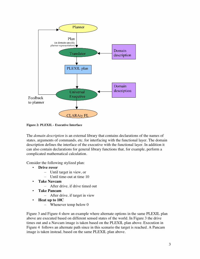
Figure 2: PLEXIL - Executive Interface
The domain description is an external library that contains declarations of the names of states, arguments of commands, etc. for interfacing with the functional layer. The domain description defines the interface of the executive with the functional layer. In addition it can also contain declarations for general library functions that, for example, perform a complicated mathematical calculation. Consider the following stylized plan:
• Drive rover – Until target in view, or – Until time-out at time 10
• Take Navcam – After drive, if drive timed out
• Take Pancam – After drive, if target in view
• Heat up to 10C – Whenever temp below 0
Figure 3 and Figure 4 show an example where alternate options in the same PLEXIL plan above are executed based on different sensed states of the world. In Figure 3 the drive times out and a Navcam image is taken based on the PLEXIL plan above. Execution in Figure 4 follows an alternate path since in this scenario the target is reached. A Pancam image is taken instead, based on the same PLEXIL plan above.

4
Figure 3: An example of execution where the drive times out.
Figure 4: An example of execution where the target is reached.
The domain specification given for this scenario contains the following mapping: Commands: void rover_drive(int speed); void rover_stop(); void take_navcam(); void take_pancam(); void turn_on_heater(); StateNames: temperature, target_in_view;
Here, Commands are function calls provided by the low level interface to the rover (functional layer) and StateNames are sensed or derived values that can be accessed from the functional layer. Note that the actual code sent to the Universal Executive will be in XML, which is a fairly standard representation for information exchange, but is not easy to read. Example PLEXIL syntax for executing the above scenario is shown in Table 1.
Drive Pancam
Heat Heat
Temp:
Time: 0 5 10
Target
Drive Navcam
Heat Heat
Temp:
Time: 0 5 10
Target

5
2 PLEXIL Syntax 2.1 Introduction The PLEXIL plan execution language is based on a hierarchical representation of execution nodes. Execution nodes describe both initiation of real-world actions, and the control of their execution. The nodes are arranged into hierarchical trees where leaf nodes are action nodes and internal nodes are control nodes. The execution of each node is governed by a set of conditions, such as when the node gets activated and when it is done. When action
Node: { NodeID: DriveToTarget; Boolean drive_done, timeout; NodeList: { Command: rover_drive(10); When AbsoluteTimeWithin:{10, POSITIVE_INFINITY} Sequence:{ Command: rover_stop(); Assign: timeout=true; } When LookupWithFrequency{target_in_view,10}==true; Sequence:{ Command: rover_stop(); Assign: drive_done=true; } When timeout==true Command: take_navcam(); When drive_done==true Command: take_pancam(); Node:{ NodeID: Heater; StartCondition: LookupOnChange{“temperature”}<0 EndCondition: LookupOnChange{“temperature”}>=10 RepeatUntilCondition: false; Command: turn_on_heater(); } }
}
Table 1: Plexil syntax for the example shown in Figure 3 and Figure 4

6
nodes are executed, commands are sent to the rover, whereas when internal nodes are executed, they are expanded to the next level of nodes in the tree. For a simple example, consider the following PLEXIL plan, with PLEXIL syntax shown in bold and domain specific variables in normal font:
Node:{ NodeId: DriveUntilStuck; RepeatUntilCondition: LookupOnChange{“Rover:wheelStuck”}==false; NodeList:{ Node:{ DriveOneMeter Command: Rover:Drive(1); } } }
The plan has one action node, which drives the rover one meter, by calling the appropriate command in the functional layer. The plan then has one control node, which simply keeps repeating the action node until the rover is stuck. The question of whether the rover is stuck is answered by lookupOnChange, which requests information from the functional layer. In this section, we describe the core notions and elements of the PLEXIL syntax. The full grammar is given in Appendix A.
2.2 Node Description There are three types of nodes in PLEXIL. The internal or NodeList nodes simply contain a list of child nodes. The action node types can be split into two types - external action nodes, i.e., Command nodes, and internal action nodes, also known as Assignment nodes. Each node has the following elements, called NodeAttributes. NodeAttributes:
Identifier (NodeID): A unique symbolic name StartCondition: Boolean expression EndCondition: Boolean expression PreCondition: Boolean expression PostCondition: Boolean expression InvariantCondition: Boolean expression RepeatUntilCondition: Boolean expression Priority: Integer Variables: List of local variable declarations Interface: List of variables “passed” to node
The execution of a node is driven by the node conditions, which are Boolean expressions. Conditions capture internal and external information as well as temporal relationships. A NodeID is a unique identifier for a node. NodeIDs are locally scoped. Hence node A and node B may both have children called C. The child of node A is referenced as A.C, the child of node B as B.C, etc. Two siblings in the node tree are not allowed to have the same name.

7
Nodes also have type-specific elements called the NodeBody. For list nodes, the element is a list of nodes; for assignment nodes, it is an assignment statement where the left-hand side is a parameter variable for that node; and for command nodes it is a call to a functional layer function. NodeBody: NodeList or Assignment or Command
2.3 External and Internal Information
2.3.1 External States To control execution, PLEXIL node elements may acquire information from world events and states. In PLEXIL we refer to world events and states as world state. The specific names used to look up world state are defined in a domain description. Access to events and states is via one-time lookups, notifications of change in value, or lookups at a given frequency. The most common update is for temporal information, such as a temporal value, e.g., a comparison like:
AbsoluteTimeWithin(“2005-10-09 14H06M12S UTC” , PLUS_INFINITY)
In the example above an event will be triggered when the absolute time is in the interval [“2005-10-09 14H06M12S UTC”, PLUS_INFINITY] PLEXIL expects that all lookups, commands, and general function calls have no side effects. In other words, they only affect the state of execution through the value they return.
2.3.2 Internal Variables In addition to the external states, a PLEXIL plan has access to the internal state of a node. There are a number of internal variables, such as the start and end times of each state of a node, the execution state of a node, etc. These are typically used to either track the state of PLEXIL execution, or to store information from external states. These variables are global and are referenced with a structure member notation:
node.state
node.state.Timepoint
node.outcome
node.failureType
Timepoints are integers that are bound to actual values at run time. The start and end Timepoint of each node state are stored.
2.3.3 Declared Local Variables Other variables are defined as local variables in nodes. Variable declarations are similar to corresponding declarations in programming languages. A counter, for example, could be defined in a node that leads to a looping structure:
Integer i=0

8
Variables passed as parameters to lookups, commands, and functions are passed by value. Hence the value of these variables is not changed.
2.3.4 Interfaces Finally, declared variables can appear in the interface of nodes. Interface variables that are read-only are specified with the keyword in and interface variables that are read-write are specified with the keyword inout. inout interface variables are passed by reference from a parent node to a child node. A child of a node only has access to the variables declared in the parent that are explicitly passed via the interface. If a node has a variable in its interface, this variable must be in the interface of all the ancestor nodes up to the node that declared it.
2.4 Information Access and Update
2.4.1 Lookups Lookups can appear in Assignments or Conditions. Lookups are of three types:
1. LookupOnChange: LookupOnChange{“Rover battery level”, 1}
2. LookupWithFrequency : LookupWithFrequency{“Rover battery level”, 10)
3. LookupNow: LookupNow{“Rover battery level”}
The value of world states can be accessed via lookups. Each external state is identified by a domain-specific name, e.g., “Rover battery level”. A LookupNow which is a single (request-based) lookup simply specifies the name, e.g.:
LookupNow{“Rover battery level”}
and the value returned is the value of state “Rover battery level” when the lookupNow is done. A LookupWithFrequency which is a repeated lookup specifies a frequency for checking the state value, e.g.:
LookupWithFrequency{“Rover battery level”, 10}
meaning that the state value should be checked 10 times per second. A LookupOnChange is an event-based repeated lookup and returns the state value whenever it changes. A tolerance parameter may be specified to restrict the value to be returned only when it changes by more than the specified tolerance, which is 1V here. LookupOnChange {“Rover battery level”, 1}
The return value of a lookup is of any of the types allowed in the domain description.

9
Note that an internal PLEXIL event may or may not be triggered when a value is returned or even when the value changes. An internal PLEXIL event is generated only when an expression in a condition evaluates to true.
2.4.2 Assignment An Assignment is of the form: Variable = Expression where, the Expression can be a declared variable (including interface variable), an internal state variable (Node.state.Timepoint), a LookupOnce, a constant, or a numeric operation. The LHS (Left Hand Side) of the assignment (Variable) can only be a declared variable including interface variable.
2.4.3 Command A Command is of the form: Variable_to_store_return_value = Command_name list_of_arguments Commands are the interface to the functional layer, or library calls (e.g. functions to perform complex computation) specified in the domain description. The command name is specified in the domain description. The arguments to the command may be variables, declared or internal states, or constants. Although numeric operations and lookups are not allowed in the list of arguments, this is not a real limitation since assignments may be used to assign values to variables that may be used as parameters to commands. The Variable_to_store_return_value of a command is optional. It is a variable that must be previously declared in the node or passed through its interface from an ancestor.
2.4.4 Conditions Conditions drive the execution of each node. Each condition is evaluated with a Boolean expression. Boolean expressions are arbitrary logical formulas, without quantification, where each predicate is either a temporal relation or a data relation. Relations are based on Boolean expressions or standard comparisons, such as equality, inequality, “less than or equal,” etc. Relations can refer to either internal variables, external state and event information, or time. We allow getting current time through a lookup. Temporal relations CurrentTimeWithin and AbsoluteTimeWithin are also provided as syntactic sugar. Based on the way conditions are checked, we have two types of conditions: gate conditions (monitored continuously) and check conditions (checked once): Gate conditions:
• StartCondition • EndCondition • InvariantCondition

10
Check conditions:
• PreCondition • PostCondition • RepeatUntilCondition
All of the above conditions may be Data or Temporal conditions or Boolean combinations of them. Data conditions are constraints on internal or external variables, which are read via lookups (details in section 3.2). Temporal conditions specify absolute time constraints or time constraints relative to Timepoints in nodes. Some example conditions:
CurrentTimeWithin{node1.FINISHED.START, +[20S,30S]}
LookupOnChange{“Rover:batteryCharge”} > 120.0
node3.state == FINISHED && node3.outcome == SUCCESS
Here, node1.FINISHED.START represents the Timepoint at which node1 entered state FINISHED. The RelativeTimeWithin condition above may be understood by representing current time explicitly as T. Then CurrentTimeWithin{node1.FINISHED.start, [20S,30S]} is equivalent to:
T ∈ [node1.state.FINISHED.START+20S, node1.FINISHED.START+30S]
Lookups that appear in gate conditions must be of type event based or frequency based, and lookups that appear in check conditions must be request based.
2.5 Domain Description Syntax The domain description syntax includes the following elements:
• List of state variables that may be accessed through lookups:
StateVariables: ”StateVariables:{“ (Type StateVariableName “;” )* “}”
• List of commands and general functions:
FunctionDeclaration: ”FunctionDeclaration: {” (Type
FunctionName ArgumentDeclaration* “;”)* “}”
ArgumentDeclaration : Type ArgumentName “;”
• Interrupt handlers (other function declarations) to be invoked when a call to the
functional layer needs to be interrupted can also be specified:

11
FunctionInterrupt: “FunctionInterrupt: {“ FunctionName HandlerName ArgumentDeclaration* “}”
In PLEXIL Functions, Commands, and Assignments have no side effects. In other words, they do not affect the state of executive in any way other than through return values.
3 PLEXIL Execution Semantics 3.1 Overview of Node Execution This section describes the execution of a single node. There are three main types of nodes. A node can be:
1. A Command node 2. An Assignment node 3. A NodeList node
The attributes listed below are internal to a node, hence they cannot be modified from within a plan, but are accessible. In other words they can be read, in StartCondition, assignments, etc:
Timepoint: Time at start or end of any state state: Indicator of execution state failureType: Indicates the cause for node failure (e.g. INVARIANT_CONDITION_FAIL, PRECONDITION_FAIL, PARENT_FAIL etc.) failedExpression An integer that stores the number of the expression in the condition (from the LHS) that caused the failure. outcome: Indicates success or failure for a node, or whether the node was skipped
We assume that for each node the executive has access to the Parent and child nodes of the node. Each node must be in one and only one of the following states at any given time:
• Waiting • Executing • Finishing • Failing • Finished • Command_Failing (only for command nodes)
The completion and outcome of a node are independent. If the state of a node is Finished, all iterations of the node have completed. No node state transitions occur after this sink state. The outcome of a node is a node attribute that provides additional information about the result of node execution. A node may have any one of the following outcomes:
• SUCCESS • FAILURE • SKIPPED (node didn’t get to run) • INFINITE_LOOP (type of failure)

12
The outcome of a node is a NodeAttribute that is only valid when the node transitions out of state Executing or Failing or when it is in state Finished. An outcome SKIPPED implies that the node did not get to execute, and the outcome INFINITE_LOOP implies that the node was poorly written and had an error that created an infinite loop. The semantics of node execution is given in terms of states and transitions between states that are triggered by condition changes. At each execution step, all condition changes that may result in node state changes are processed until quiescence (in other words until all nodes are waiting on a condition change affected by an external event, or have been determined to be infinite loops). Precedence order is used to resolve conflicts. The set of condition changes that cause node state transitions are as follows:
• StartCondition True • InvariantCondition False • EndCondition True • Ancestor_InvariantCondition False • Ancestor_EndCondition True • All_children_Waiting_or_Finished True
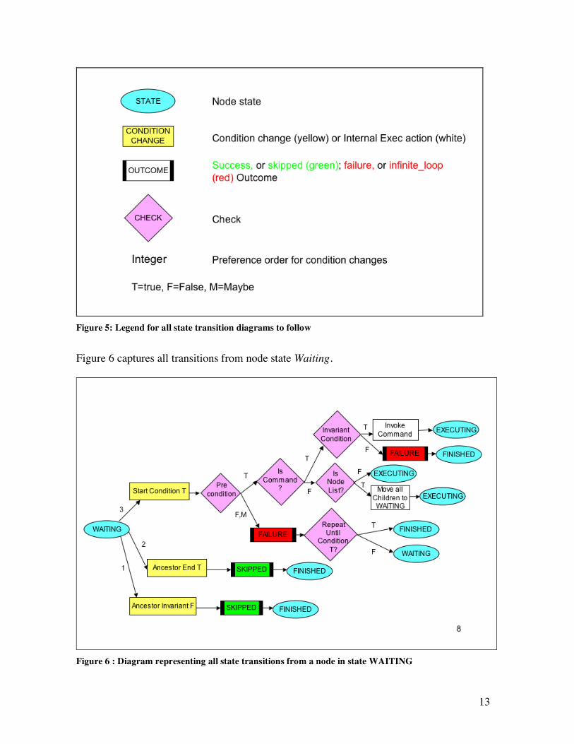
Additional details on conditions are provided in section 3.2. Figure 5 is a legend for Figure 6 to Figure 12. The ovals represent node states. The yellow rectangles represent condition changes that cause a transition from a node state. The rectangles with bars represent the outcome of a node. The lilac diamonds represent checks. Transitions are represented by directed arrows. If there are multiple condition changes that may happen simultaneously, integers are used to represent the precedence order. A condition change with precedence order 1 gets priority over any other condition change. A condition change with precedence order 2 is processed if there is no condition change with priority 1 and so on. Some checks are a binary choice between True and False. Others are a choice between True, False, and Maybe (represented as T, F, and M respectively in the figures).
13
Figure 5: Legend for all state transition diagrams to follow
Figure 6 captures all transitions from node state Waiting.
Figure 6 : Diagram representing all state transitions from a node in state WAITING

14
Figure 7: Diagram representing all state transition from a NodeList node in state EXECUTING
Figure 8: All state transitions from a Command node in state EXECUTING

15
Figure 9: All state transitions from an Assignment node in state EXECUTING
Figure 10: All state transitions from a node in state FAILING
16
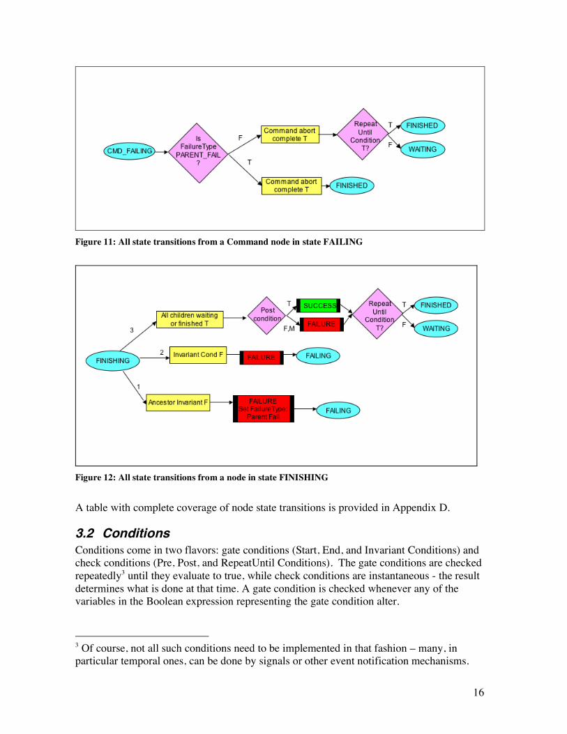
Figure 11: All state transitions from a Command node in state FAILING
Figure 12: All state transitions from a node in state FINISHING
A table with complete coverage of node state transitions is provided in Appendix D.
3.2 Conditions Conditions come in two flavors: gate conditions (Start, End, and Invariant Conditions) and check conditions (Pre, Post, and RepeatUntil Conditions). The gate conditions are checked repeatedly3 until they evaluate to true, while check conditions are instantaneous - the result determines what is done at that time. A gate condition is checked whenever any of the variables in the Boolean expression representing the gate condition alter.
3 Of course, not all such conditions need to be implemented in that fashion – many, in particular temporal ones, can be done by signals or other event notification mechanisms.

17
In addition, the conditions are also classified in an alternate way. Start, End and RepeatUntil conditions drive the execution of a node. Pre, Post, and Invariant conditions monitor the execution of a node. Hence, these conditions are also called failure conditions. If any of these conditions fail to evaluate to true, the node execution is aborted with a failure indication. Whenever a condition is no longer needed by the current state or any of the states that this node may transition to in the current iteration, it is no longer checked. Hence, when a node reaches state FINISHED, all the conditions associated with the node are no longer checked. The conditions of ancestors and children of a node may also affect node execution as described in section 3.1. Below we discuss only the affect of a conditions of a node on itself.
3.2.1 StartCondition The most commonly used gate condition is the StartCondition for a node. It determines when a node is eligible for execution, and is thus a gate condition. To specify that a node should start executing after a certain time, one can specify the following using an AbsoluteTimeWithin Temporal condition:
StartCondition: AbsoluteTimeWithin{“2005-03-21 16H20M00S UTC”, PLUS-INFINITY}
For example, a StartCondition could be: LookupOnChange{“Rover battery level”} > 10.0 && (powerTrackingNode.state == EXECUTING)
The current time is implicit in PLEXIL, but the start condition above may be understood by making the current time explicit as T. The above start condition is then:
T ∈ [“2005-03-21 16H20M00S UTC”, PLUS-INFINITY]
When the StartCondition of a node becomes true, the PreCondition is checked. If the PreCondition is true as well, the node state becomes EXECUTING, and all children of the node are created. Assignment or command nodes are executed. The default StartCondition of a node is true.
3.2.2 PreCondition A PreCondition is a check condition. When the StartCondition of a node becomes true, the PreCondition is checked. If the PreCondition evaluate to false, then the node fails before its children are created. The outcome of the node is set to FAILURE and the RepeatUntilCondition is checked to determine if the node will wait to run at a later time or terminate completely. Even though the node did not execute, since it passed its StartCondition it is considered to have undergone an iteration. The outcome will be FAILURE and the failureType will be PRECONDITION_FAIL. It is possible in the

18
implementation of the executive to save the variable bindings that made the PreCondition fail in some debugging file or core file. The default PreCondition of a node is true.
3.2.3 InvariantCondition Invariant conditions are gate conditions. They are typically used to capture constraints that must be true for the entire duration of the execution of a node. Should the InvariantCondition become false, the node fails and transitions to state FAILING. The outcome is set to FAILURE and the failureType is INVARIANT_CONDITION_FAIL. The default InvariantCondition of a node is true.
3.2.4 EndCondition The EndCondition is a gate condition. It determines when the node goals have been achieved, and execution can be wrapped up. Intuitively a parent node finishes naturally when its children are FINISHED or when its EndCondition becomes true (in which case the children are signaled to wrap up). Note that the EndCondition does not lead to immediate end of node execution (one iteration), as child processes may need to complete and clean up. The children are considered to have “wrapped up” if all children are either in state WAITING or FINISHED, but no other intermediate state. When the EndCondition of a node becomes true, the node transitions to the state FINISHING. The intent of state FINISHING is to wait for active children to complete. An example of an EndCondition would be a confirmation from the functional layer that something has been successfully completed; for example:
EndCondition: LookupOnChange{“E-box temperature”, 1} > 20.0
The default EndConditions of a node are different depending on the type of node: The default EndCondition of a NodeList node is “All children finished”. The default EndCondition of a Command node is “Command call returned” and the default EndCondition of an Assignment node is “Assignment complete”. The actual EndCondition of a Command and Assignment node is a conjunction of the explicitly specified expression for the EndCondition and the default condition. This is not the case for a NodeList node. When an explicit EndCondition is specified for a NodeList node, it replaces the default.
3.2.5 PostCondition PostConditions are check conditions. The PostConditions of a node are checked after each iteration of the node is completed. If the PostCondition is false, the node terminates with outcome FAILURE and the relevant failure information is saved (the specific conjunct is saved). Note that since a node’s PostCondition is not checked until all children have completed, there is no need to halt running children. PostConditions are typically redundant checks that ensure that the result of node execution was as desired.
19
3.2.6 RepeatUntilCondition RepeatUntilConditions are check conditions. Their purpose is to determine whether the node should be re-run, or whether it is fully done and should be transitioned to state FINISHED (no longer needed for the execution of the current plan). When a node has completed an iteration of execution, its RepeatUntilCondition is checked. If it is true, then the node is re-activated and put in state WAITING, and waits for its StartCondition to become true again. Note that the node’s internal variables are all reset, just as if the node were running for the first time4. Once the node has ended the execution of the current iteration, i.e., its EndCondition is true and all remaining children have completed their execution, the RepeatUntilCondition is checked. If it evaluates to true, the node is eligible for execution when its StartCondition becomes true. Otherwise, the node is permanently removed from the execution process. An example of a RepeatUntilCondition is given in section 2.1, but an even more common use is that of a loop counter check shown below:
Repeat-until-condition: counter < 10
3.3 Node Termination There is a distinction between the completion of a single iteration of a node and the completion of all iterations of a node. The completion of all iterations of a node is represented by state FINISHED. After each iteration of a node, the RepeatUntil condition of the node is checked. The node resumes another iteration (goes back to state WAITING) until the RepeatUntil condition is satisfied. Note that there are no static variables in a node and values are not maintained between iterations. Variables such as counters are thus declared in the parent. All the conditions associated with a node that has FINISHED execution are no longer monitored. If a node’s own InvariantCondition fails, the instantiation used in the condition evaluation is saved. If its parent caused the termination, a link to the ancestor node is saved as an explanation. If the terminated node is a list node, all children are terminated. Terminating non-executing children implies that the StartConditions of these nodes will no longer be monitored. If the terminated node is a command node, then the ongoing call into the functional layer has to be interrupted. The domain description provides one way to do this. The interface to the functional layer may also provide a more drastic way, such as killing a thread. In PLEXIL, node “success” and “failure” is separate from the temporal state of a node. The outcome field stores the “success” or “failure” of a node and the state field stores the temporal state of a node, which may have the values WAITING, EXECUTING, FINISHING, FAILING, and FINISHED. This is useful, for instance, when there is a sequence of nodes, with one node constrained to start after another node is done. Often one
4 This is equivalent to saying that nodes do not have static local variables.

20
wants for subsequent nodes in a chain should to continue even if one of the nodes in that sequence has been terminated.
3.4 Node Synchronization No two assignment nodes can execute in parallel if they write to the same variable. All events received by the executive are queued.
3.5 Events An event is either:
• A change in the state of the external world represented by declared variables or lookups
• A change in the state of internal variables of the executive
3.6 Condition Changes Events are queued. Each event is processed in the order in which it was received. All conditions affected by the event are evaluated and one or more condition changes may evaluate to true. Given only the previous state and any combination of the following condition changes, the next state of a node is determined:
• StartCondition T • InvariantCondition F • EndCondition T • Ancestor_inv_condition F • Ancestor_end_condition T • All_children_waiting_or_finished T
3.7 Expanded Semantics of Lookups and Conditions There are a number of parameters for lookups. The subsets of parameters parsed for a condition or assignment are different. For example, if a frequency is specified with a lookup in an assignment it is ignored since an assignment is considered to be atomic. An internal PLEXIL event is generated when the value returned by a lookup (either event based or frequency based) has changed (i.e, the previous value is different from the current value by more than the Tolerance, if specified). Note that a change in value is reported based only on the information from lookups. The true state of the world may change at a higher frequency. Example 1: Consider the example shown in Figure 13. There may be three classes of lookups:
1) Lookup with Frequency
StartCondition: LookupWithFrequency{x, 0.1;}
2) Lookup triggered by change

21
StartCondition: LookupOnChage{x, 0.5}
3) Lookup now These lookups appear in check conditions (such as the PreCondition below) or in
Assignments. This lookup is evaluated only once at the time the condition is evaluated.
StartCondition: LookupOnChange{y} == 4 PreCondition: LookupNow{x}!=1
Figure 13: Illustration of the difference between event-based lookups, frequency-based lookups, and one-time request-based lookups
In this example, the first lookup (frequency based) returns the value of x at time T=10, T=20 and T=30 before an internal event is triggered when the value of x changes at T=30. In
Figure 13 a solid square represents that the value of the variable represented within the square was returned, and a dashed square represents that in addition to the value being returned an event was also triggered. In the third case, the value of y is returned in an event-based manner from the functional layer when it changes. The lookup for the value of x is part of a PreCondition and is checked only once at the instance when the StartCondition is satisfied. The StartCondition in this example is satisfied at T=35 when y=4, hence the lookup for x is performed at T=35 and the value of x is returned. In this example the PreCondition would evaluate to false Example 2: Consider another example:

22
StartCondition:{ LookupWithFrequency{x, 0.1} == 1 ^ LookupNow{y} == 3}
As shown in Figure 14 , an event is triggered at time T=10 to initialize the value of x from UNKNOWN to 0. The StartCondition is checked, but the value of y at this point is still UNKNOWN, so the condition does not yet hold. When the value of y changes to 2 another event is triggered. This initializes the value of y to 2, and the StartCondition is checked once again. In this case, the StartCondition evaluates to false since the value of x is 0. The StartCondition is checked again at T=20, but since the value of x is still 0 the condition still evaluates to false. The same happens when the value of y changes to 3. At time T=30, a lookup of the value of x returns 1 and the StartCondition is checked again. This time it evaluates to true.
Figure 14: Example of a condition that involved two lookups
Lookups simply read state values. The domain declaration contains a list of state names that PLEXIL expects to look up “safely.” In other words, looking up these states should not change any states. Note that an implementation of the executive may choose to cache state values without violating this requirement. It is good form to ensure that anything specified as a lookup in the domain description is known to have a low latency return value, else it may delay the execution of a node in which it is used (for example, if it were used in a PreCondition).

23
Only LookupWithFrequency and LookupOnChange may be used in gate conditions (such as start conditions, invariant conditions, and end conditions). If the lookup has a frequency, the variables in these conditions are checked at the specified frequency. If a LookupOnChange is specified, the variable is checked asynchronously.
StartCondition:{ LookupOnChange{“Rover battery level”} > 10.0
&& LookupWithFrequency{“E-box temperature”, 1} > 20.0
&& {powerTrackingNode.state == EXECUTING}
&& AbsoluteTimeWithin{“2005-03-21 16H20M00S UTC”, PLUS-INFINITY}}
In the example above, an asynchronous event is triggered whenever the rover battery level changes. The value of the E-box temperature is checked at a frequency of 1 Hz. If this value has changed since the last time it was checked, an internal event is triggered. The state of the powerTrackingNode is maintained internally and it triggers an event when it changes. Time too is maintained internally and events based on time are triggered internally by the executive. The start condition specified in the example above is checked whenever an event corresponding to the a change in the rover battery level or the E-box temperature is triggered or if the state of powerTrackingNode changes or if the current time enters the window [“2005-03-21 16H20M00S UTC”, PLUS-INFINITY]. Only LookupNow may be used in a check condition (such as PreCondition, and PostCondition) or an Assignment.
3.8 Commands Calls to commands do NOT block execution. And command nodes do not finish until the command call completes (so they can have duration).
3.9 Types There are two extra values for data (FAIL and UNKNOWN) and one extra value MAYBE for Boolean expressions. The domain of declared variables and values returned by lookups and commands (which may, or may not, be assigned to declared variables) is extended with two additional values – UNKNOWN and FAIL. UNKNOWN means uninitialized and FAIL means that the lookup or command failed. UNKNOWN or FAIL have non-standard interpretation in a Boolean expression. Below is an illustration of a non-standard truth value we call MAYBE. Assume we have an invariant condition: LookupWithFrequency{"Temperature", 1} > 0 && LookupWithFrequency{"Battery", 0.01} > 20 At initialization the values are:
Temperature = UNKNOWN and
24
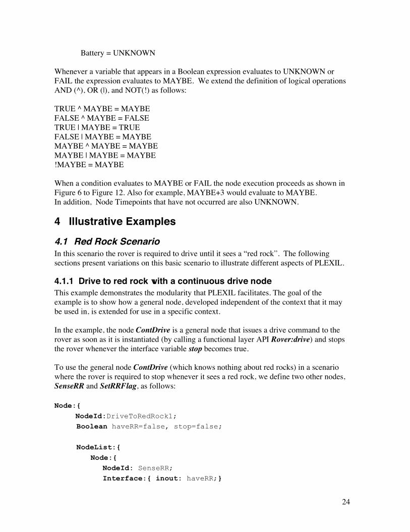
Battery = UNKNOWN Whenever a variable that appears in a Boolean expression evaluates to UNKNOWN or FAIL the expression evaluates to MAYBE. We extend the definition of logical operations AND (^), OR (|), and NOT(!) as follows: TRUE ^ MAYBE = MAYBE FALSE ^ MAYBE = FALSE TRUE | MAYBE = TRUE FALSE | MAYBE = MAYBE MAYBE ^ MAYBE = MAYBE MAYBE | MAYBE = MAYBE !MAYBE = MAYBE When a condition evaluates to MAYBE or FAIL the node execution proceeds as shown in Figure 6 to Figure 12. Also for example, MAYBE+3 would evaluate to MAYBE. In addition, Node Timepoints that have not occurred are also UNKNOWN.
4 Illustrative Examples 4.1 Red Rock Scenario In this scenario the rover is required to drive until it sees a “red rock”. The following sections present variations on this basic scenario to illustrate different aspects of PLEXIL.
4.1.1 Drive to red rock with a continuous drive node This example demonstrates the modularity that PLEXIL facilitates. The goal of the example is to show how a general node, developed independent of the context that it may be used in, is extended for use in a specific context. In the example, the node ContDrive is a general node that issues a drive command to the rover as soon as it is instantiated (by calling a functional layer API Rover:drive) and stops the rover whenever the interface variable stop becomes true. To use the general node ContDrive (which knows nothing about red rocks) in a scenario where the rover is required to stop whenever it sees a red rock, we define two other nodes, SenseRR and SetRRFlag, as follows: Node:{ NodeId:DriveToRedRock1; Boolean haveRR=false, stop=false;
NodeList:{ Node:{
NodeId: SenseRR; Interface:{ inout: haveRR;}

25
StartCondition: { LookupWithFrequency:{“found RR”, 10}==true }
Assignment: haveRR=true; }
Node:{ NodeId:ContDrive Interface:{ in: stop; }
NodeList:{ Node:{
NodeId: StartDrive; Command: "Rover:drive";
} Node:{
NodeId: StopDrive; Interface:{ in stop;} StartCondition:
{ stop==true && startDrive.state==FINISHED }
Command: "Rover:stop"; } }
}
Node:{ NodeId: SetRRFlag
Interface:{ inout stop; in haveRR; } StartCondition: haveRR == true; Assignment: stop = true; }
} }
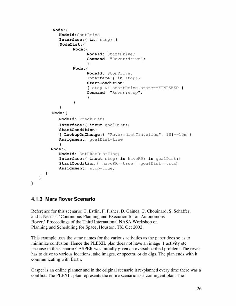
4.1.2 Drive 10m or to red rock with continuous drive node In this example, the rover is required to drive until it either sees a red rock or has traveled a distance of 10m. The purpose of this example is to further emphasize the modularity of PLEXIL. This example uses the ContDrive and SenseRR nodes from section 4.1.1, but uses the SetRRorDistFlag node instead of the SetRRFlag node to stop the rover when it either sees a red rock or has traveled a distance of 10m. Node:{ DriveRRorDist Boolean haveRR=false, stop=false; NodeList:{
Node:{ NodeId: SenseRR;
Interface:{ inout: haveRR;} StartCondition:
{ LookupWithFrequency:{“found RR”, 10}==true } Assignment: haveRR = true; }
26
Node:{ NodeId:ContDrive Interface:{ in: stop; }
NodeList:{ Node:{
NodeId: StartDrive; Command: "Rover:drive";
} Node:{
NodeId: StopDrive; Interface:{ in stop;}
StartCondition: { stop && startDrive.state==FINISHED }
Command: "Rover:stop"; } }
} Node:{ NodeId: TrackDist;
Interface:{ inout goalDist;} StartCondition: { LookupOnChange:{ "Rover:distTravelled", 10}==10m }
Assignment: goalDist=true } Node:{ NodeId: SetRRorDistFlag; Interface:{ inout stop; in haveRR; in goalDist;} StartCondition:{ haveRR==true | goalDist==true} Assignment: stop=true; } } }
4.1.3 Mars Rover Scenario Reference for this scenario: T. Estlin, F. Fisher, D. Gaines, C. Chouinard, S. Schaffer, and I. Nesnas. "Continuous Planning and Execution for an Autonomous Rover," Proceedings of the Third International NASA Workshop on Planning and Scheduling for Space, Houston, TX, Oct 2002. This example uses the same names for the various activities as the paper does so as to minimize confusion. Hence the PLEXIL plan does not have an image_1 activity etc because in the scenario CASPER was initially given an oversubscribed problem. The rover has to drive to various locations, take images, or spectra, or do digs. The plan ends with it communicating with Earth. Casper is an online planner and in the original scenario it re-planned every time there was a conflict. The PLEXIL plan represents the entire scenario as a contingent plan. The

27
contingencies that did not come up in the CASPER scenario are not currently modeled in the plan for simplicity. At first the rover is initialized. Then the rover should go to location 1 and take a spectrometer reading, spec_1. After this the rover should go to location 2 and take an image, img_2. If an obstacle is encountered enroute the navigator must plan a new path to location 2. If the estimated time to reach location 2 ever exceeds the allowed window of time the rover should abort the drive. The rover should then go to location 3 and take an image, img_3. If the image data cannot be compressed as much as expected and the image takes up more memory than expected, not all science data will be able to be stored for this day. Hence the low priority spectrometer 2 reading, spec_2, should be skipped. Then the rover should go to location 4 and do a dig, dig_2. If more energy is used than expected there will not be enough energy to complete all the activities and so a lower priority science goal, dig_1 (that is scheduled later in the plan) must be skipped in order to ensure that there will be enough energy to complete other high priority science goals and the end of day communication activity. After this the rover should go to location 5 and take a spectrometer reading, spec_2.After this the rover should to to location 6 and take an image, img_4. Then it should go to location 7 and do a dig, dig_1. Then it should go to location 2 and take an image, img_2. In the end it should communicate with earth. CASPER SCENARIO IN CORE PLEXIL SYNTAX: Node:{ NodeId: CasperScenario Interface:{ inout: have_spec_1, have_spec_2, have_img_2, have_img_3, have_img_4, done_dig_1, done_dig_2, done_comm} PostCondition: Comm.outcome==SUCCESS InvariantCondition: InitRover.outcome==SUCCESS ^ InitRoverPos.outcome==SUCCESS NodeList:{ Node:{ NodeId: InitRover Command: "Rover:init" } Node:{ NodeId: InitRoverPos StartCondition: InitRover.state==FINISHED Command: "Rover:setLocation(0,0,0)" } Node:{ NodeId: Setup_Goto_1 StartCondition: InitRoverPos.state==FINISHED Command: "Navigator:turn(loc_1)" } Node:{ NodeId: Goto_1 StartCondition: Setup_Goto_1.state==FINISHED
28
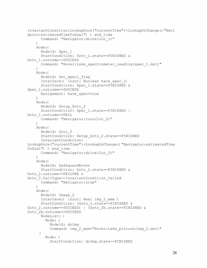
InvariantCondition:LookupOnce("currentTime")+LookupOnChange:{"Navigator:estimatedTimeToGoal"} > end_time Command: "Navigator:drive(loc_1)" } Node:{ NodeId: Spec_1 StartCondition: Goto_1.state==FINISHED & Goto_1.outcome==SUCCESS Command: "Rover:take_spectrometer_reading(spec_1.dat)" } Node:{ NodeId: Set_spec1_flag Interface:{ inout: Boolean have_spec_1} StartCondition: Spec_1.state==FINISHED & Spec_1.outcome==SUCCESS Assignment: have_spec=true } Node:{ NodeId: Setup_Goto_2 StartCondition: Spec_1.state==FINISHED | Goto_1.outcome==FAIL Command: "Navigator:turn(loc_2)" } Node:{ NodeId: Goto_2 StartCondition: Setup_Goto_2.state==FINISHED InvariantCondition: LookupOnce("currentTime")+LookupOnChange:{"Navigator:estimatedTimeToGoal"} > end_time Command: "Navigator:drive(loc_2)" } Node:{ NodeId: SafeguardRover StartCondition: Goto_2.state==FINISHED & Goto_2.outcome==FAILURE & Goto_2.failType==InvariantCondition_failed Command: "Navigator:stop" } Node:{ NodeId: Image_2 Interface:{ inout: Real img_2_mem } StartCondition: (Goto_2.state==FINISHED & Goto_2.outcome==SUCCESS) | (Goto_2b.state==FINISHED & Goto_2b.outcome==SUCCESS NodeList: { Node: { NodeId: doImg Command: img_2_mem="Rover:take_picture(img_2.dat)" } Node: { StartCondition: doImg.state==FINISHED

29
Assignment: img_2_mem=LookupOnce("Rover:ram_update"); } } Node:{ NodeId: Set_img2_flag Interface:{ inout: Boolean have_img_2} StartCondition: Image_2.state==FINISHED & Image_2.outcome==SUCCESS Assignment: have_img_2=true } Node:{ NodeId: Setup_Goto_3 StartCondition: Image_2.state==FINISHED | Goto_2.outcome==FAIL Command: "Navigator:turn(loc_3)" } Node:{ NodeId: Goto_3 StartCondition: Setup_Goto_3.state==FINISHED InvariantCondition: LookupOnce("currentTime")+LookupOnChange:{"Navigator:estimatedTimeToGoal"} > end_time Command: "Navigator:drive(loc_3)" } Node:{ NodeId: Image_3 Interface:{ inout: Real img_3_mem } StartCondition: Goto_3.state==FINISHED & Goto_3.outcome==SUCCESS Command: img_3_mem = "Rover.take_picture(img_3.dat)" } Node:{ NodeId: Set_img3_flag Interface:{ inout: Boolean have_img_3} StartCondition: Image_3.state==FINISHED & Image_3.outcome==SUCCESS Assignment: have_img_3=true } Node:{ NodeId: Setup_Goto_4 StartCondition: Image_3.state==FINISHED | Goto_3.outcome==FAIL Command: "Navigator:turn(loc_4)" } Node:{ NodeId: Goto_4 StartCondition: Setup_Goto_4.state==FINISHED InvariantCondition: LookupOnce("currentTime")+LookupOnChange:{"Navigator:estimatedTimeToGoal"} > end_time Command: "Navigator:drive(loc_4)" }

30
Node:{ NodeId: Dig_2 Interface:{ inout: Real dig_2_energy } StartCondition: Goto_4.state==FINISHED & Goto_4.outcome==SUCCESS Command: dig_2_energy="Arm:dig(dig_2.dat)" } Node:{ NodeId: Set_dig2_flag Interface:{ inout: Boolean done_dig_2} StartCondition: Dig_2.state==FINISHED & Dig_2.outcome==SUCCESS Assignment: done_dig_2=true } Node:{ NodeId: Setup_Goto_5 StartCondition: (Dig_2.state==FINISHED | Goto_4.outcome==FAILED) & img_3_mem < 10 Command: "Navigator:turn(loc_5)" } Node:{ NodeId: Goto_5 Interface: {in: Real img_3_mem} StartCondition: Setup_Goto_5.state==FINISHED InvariantCondition: LookupOnce("currentTime")+LookupOnChange:{"Navigator:estimatedTimeToGoal"} > end_time Command: "Navigator"drive(loc_5)" } Node:{ NodeId: Spec_2 StartCondition: Goto_2.state==FINISHED & Goto_2.outcome==SUCCESS Command: "Rover:take_spectrometer_reading(spec_2.dat)" } Node:{ NodeId: Set_spec2_flag Interface:{ inout: Boolean have_spec_2} StartCondition: Spec_2.state==FINISHED & Spec_2.outcome==SUCCESS Assignment: have_spec=true } Node:{ NodeId: Setup_Goto_6 StartCondition: Spec_2.state==FINISHED | Goto_5.outcome==FAIL Command: "Navigator:turn(loc_6)" } Node:{ NodeId: Goto_6 StartCondition: Setup_Goto_6.state==FINISHED

31
InvariantCondition: LookupOnce("currentTime")+LookupOnChange:{"Navigator:estimatedTimeToGoal"} > end_time Command: "Navigator:drive(loc_6)" } Node:{ NodeId: Image_4 Interface:{ inout: Real img_4_mem } StartCondition: Goto_4.state==FINISHED & Goto_4.outcome==SUCCESS Command: img_4_mem="Rover:take_picture(img_4.dat)" } Node:{ NodeId: Set_img4_flag Interface:{ inout: Boolean have_img_4} StartCondition: Image_4.state==FINISHED & Image_4.outcome==SUCCESS Assignment: have_img_4=true } Node:{ NodeId: Setup_Goto_7 StartCondition: (Image_4.state==FINISHED | Goto_6.outcome==FAIL) & dig_1_energy < 1000 Command: "Navigator:turn(locl_7)" } Node:{ NodeId: Goto_7 Interface: {in: dig_1_energy} StartCondition: Setup_Goto_7.state==FINISHED InvariantCondition: LookupOnce("currentTime")+LookupOnChange:{"Navigator:estimatedTimeToGoal"} > end_time Command: "Navigator:drive(loc_7)" } Node:{ NodeId: Dig_1 Interface:{ inout: Real dig_1_energy } StartCondition: Goto_4.state==FINISHED & Goto_4.outcome==SUCCESS Command: dig_1_energy="Arm:dig(dig1.dat)" } Node:{ NodeId: Set_dig1_flag Interface:{ inout: Boolean done_dig_1} StartCondition: Dig_1.state==FINISHED & Dig_1.outcome==SUCCESS Assignment: done_dig_1=true } Node:{ NodeId: Setup_Goto_2b StartCondition: Spec_1.state==FINISHED | Goto_1.outcome==FAIL

32
Command: "Navigator_turn(loc_2b)" } Node:{ NodeId: Goto_2b StartCondition: have_img_1==false & (Dig_1.state==FINISHED | Goto_7.outcome==FAIL) InvariantCondition: LookupOnce("currentTime")+LookupOnChange:{"Navigator:estimatedTimeToGoal"} > end_time Command: "Navigator:drive(loc_2b)" } Node:{ NodeId: Setup_Comm StartCondition: Image_2.state==FINISHED | (Goto_2.outcome==FAIL & (Spec_1.state==FINISHED | Goto_1.outcome==FAIL)) Command: "Navigator:turn(loc_7)" } Node:{ NodeId: Goto_7 StartCondition: Setup_Comm.state==FINISHED Command: "Navigator:drive(loc_7)" } Node: { NodeId: Comm StartCondition: Goto_7.state==FINISHED InvariantCondition: AbsoluteTimeWithin(1800, 2000, 10) Command: "Rover:Comm" } } }
5 Practical Issues
5.1 Commonly Used Elements This section presents examples of commonly used execution control structures and describes how they can be implemented in PLEXIL.
5.1.1 Time-stamped commands A time-stamped command is one that is to be executed at a specific time. To execute command <cmd> at time <time> in PLEXIL:
Node:{ NodeId: doTimeStampedCommand; Start-cond: AbsoluteTimeWithin{<time>,+inf}; Command: <cmd>; }
33
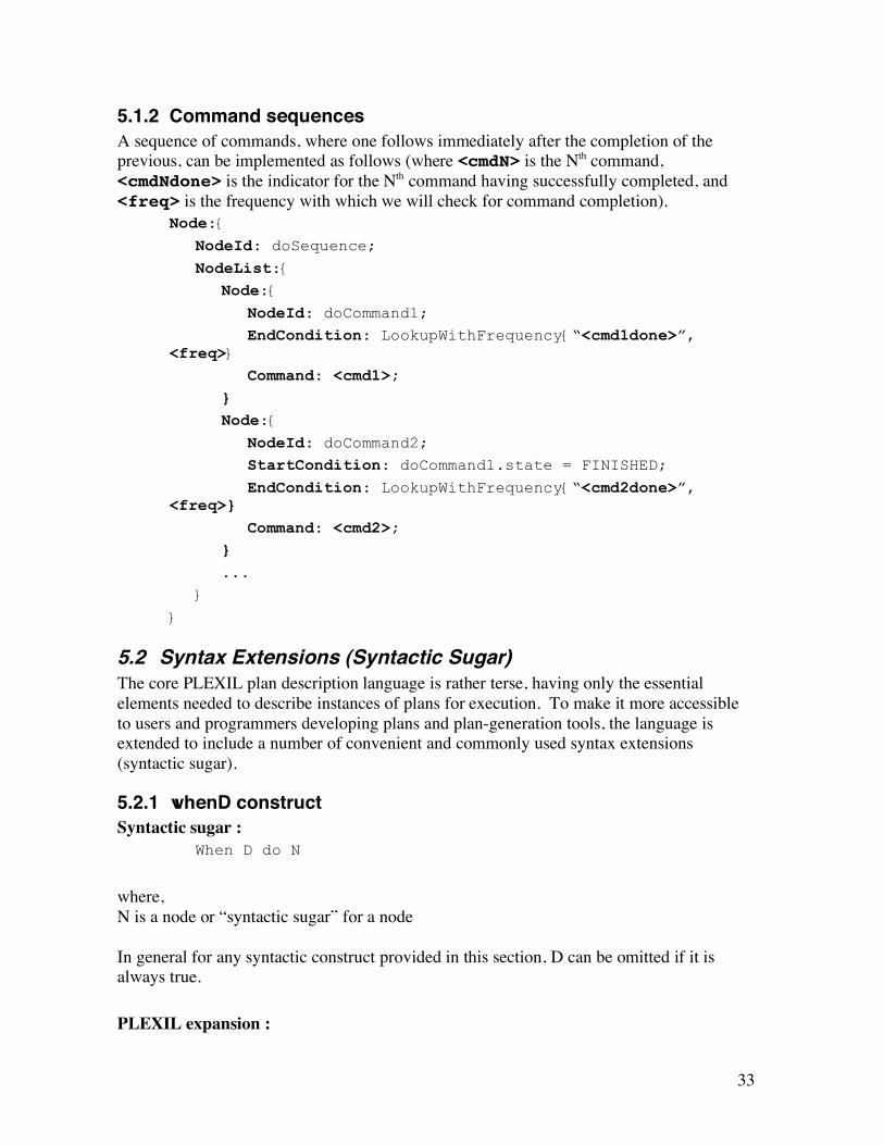
5.1.2 Command sequences A sequence of commands, where one follows immediately after the completion of the previous, can be implemented as follows (where <cmdN> is the Nth command, <cmdNdone> is the indicator for the Nth command having successfully completed, and <freq> is the frequency with which we will check for command completion).
Node:{ NodeId: doSequence; NodeList:{ Node:{ NodeId: doCommand1; EndCondition: LookupWithFrequency{“<cmd1done>”, <freq>} Command: <cmd1>; } Node:{ NodeId: doCommand2; StartCondition: doCommand1.state = FINISHED; EndCondition: LookupWithFrequency{“<cmd2done>”, <freq>} Command: <cmd2>; } ...
}
}
5.2 Syntax Extensions (Syntactic Sugar) The core PLEXIL plan description language is rather terse, having only the essential elements needed to describe instances of plans for execution. To make it more accessible to users and programmers developing plans and plan-generation tools, the language is extended to include a number of convenient and commonly used syntax extensions (syntactic sugar).
5.2.1 whenD construct Syntactic sugar :
When D do N
where, N is a node or “syntactic sugar” for a node In general for any syntactic construct provided in this section, D can be omitted if it is always true.
PLEXIL expansion :

34
Node:{ Interface:{ in <in vars from N>, <vars from D>; inout: <inout vars from N>;} StartCondition: D; { Node list: N
}
}
5.2.2 Sequence Syntactic sugar :
sequence N1, N2,…,Nk
PLEXIL expansion :
Node:{ NodeID: sequenceN1Nk; Interface: { in: <in vars from N1, N2, …, Nk>; inout: <inout vars from N1, N2, …, Nk>;} Node list:{ Node:{ NodeID: doN1; Interface: { in: <in vars from N1; inout: <inout vars from N1>;} Node list:{ N1
} } Node:{ NodeID: doN2;
Interface: { in <in vars from N2;
inout: <inout vars from N2>;}
StartCondition: doN1.state == FINISHED; Node list:{ N2
} } ...

35
} }
5.2.3 List Syntactic sugar :
list N1, N2,…,Nk
Equivalent to a sequence for the nodes in a NodeList
PLEXIL expansion : Node:{ NodeID: doN1; Interface: { in: <in vars from N1; inout: <inout vars from N1>;} Node list:{ N1
} } Node:{ NodeID: doN2;
Interface: { in <in vars from N2;
inout: <inout vars from N2>;}
StartCondition: doN1.state == FINISHED; Node list:{ N2
} } ...
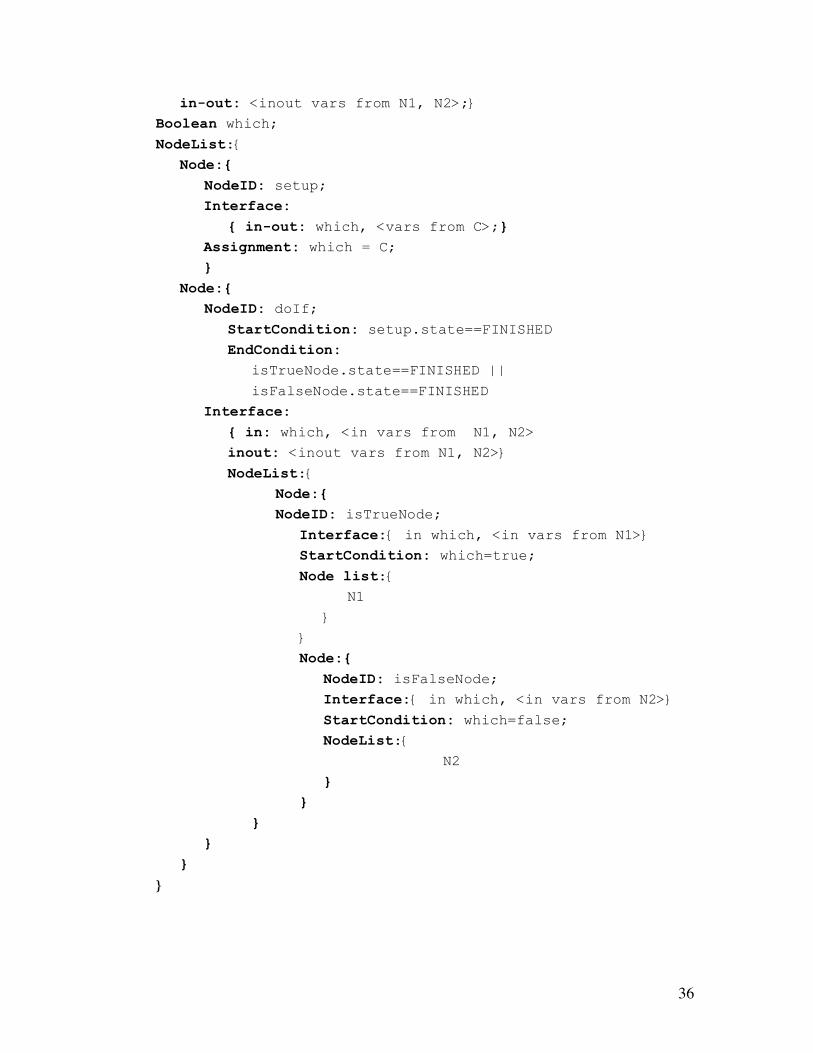
5.2.4 If-then-else Syntactic sugar :
if C then N1 else N2
PLEXIL expansion : Node:{ Interface: { in: <in vars from N1, N2>,<vars from C>;
36
in-out: <inout vars from N1, N2>;} Boolean which; NodeList:{ Node:{ NodeID: setup;
Interface: { in-out: which, <vars from C>;}
Assignment: which = C; }
Node:{ NodeID: doIf; StartCondition: setup.state==FINISHED EndCondition: isTrueNode.state==FINISHED ||
isFalseNode.state==FINISHED
Interface: { in: which, <in vars from N1, N2> inout: <inout vars from N1, N2>}
NodeList:{ Node:{ NodeID: isTrueNode; Interface:{ in which, <in vars from N1>} StartCondition: which=true; Node list:{ N1
}
}
Node:{ NodeID: isFalseNode; Interface:{ in which, <in vars from N2>} StartCondition: which=false; NodeList:{ N2
} } } } }
}
37
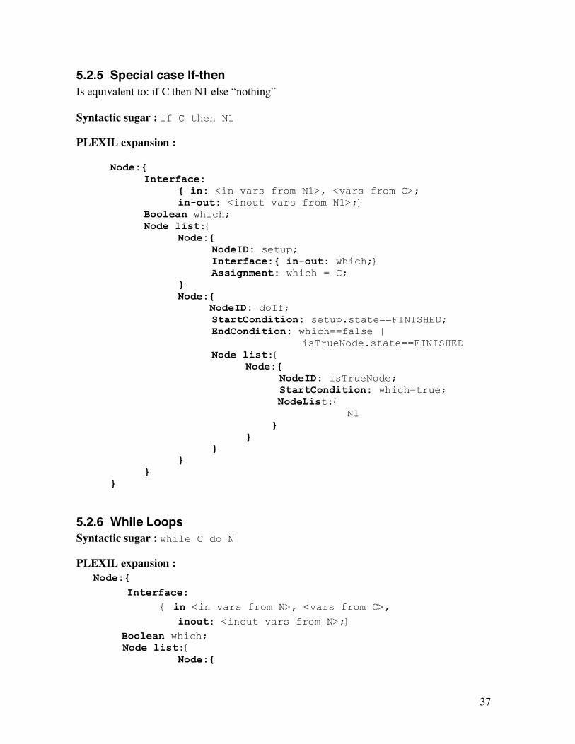
5.2.5 Special case If-then Is equivalent to: if C then N1 else “nothing” Syntactic sugar : if C then N1
PLEXIL expansion :
Node:{ Interface:
{ in: <in vars from N1>, <vars from C>; in-out: <inout vars from N1>;}
Boolean which; Node list:{
Node:{ NodeID: setup; Interface:{ in-out: which;} Assignment: which = C; } Node:{ NodeID: doIf; StartCondition: setup.state==FINISHED;
EndCondition: which==false | isTrueNode.state==FINISHED
Node list:{ Node:{ NodeID: isTrueNode; StartCondition: which=true; NodeList:{ N1 } } } } }
}
5.2.6 While Loops Syntactic sugar : while C do N
PLEXIL expansion : Node:{ Interface: { in <in vars from N>, <vars from C>, inout: <inout vars from N>;} Boolean which;
Node list:{ Node:{

38
NodeID: setup; Interface:{ in-out: which;} Assignment: which = C; }
Node:{ NodeID: doWhile; Interface: { in <in vars from N>, <vars from C>; inout: <inout vars from N>;}
StartCondition: setup.state==FINISHED; EndCondition: which==false | isTrueNode.state==FINISHED Node list:{ Node:{ NodeID: isTrueNode; StartCondition: which==true; Interface: { in <in vars from N>, <vars from
C>; inout: <inout vars from N>;} Repeat-until-condition: not C; NodeList:{ N
}
}
}
}
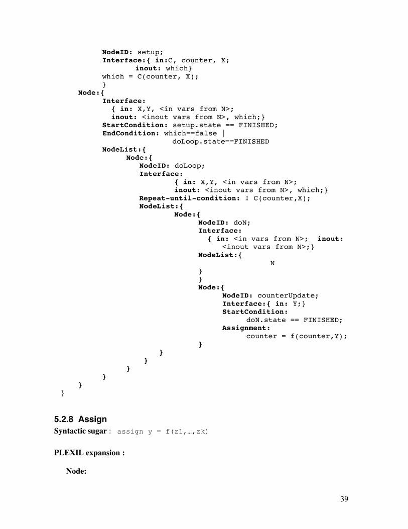
5.2.7 For Loops Syntactic sugar : for(int counter = initValue(Z), C(counter,X) f(counter,Y)) N Where, the counter type could be int, float or any other type supported by PLEXIL PLEXIL expansion : Node:{ Interface:
{ in: X,Y,Z <in vars from N>; inout: <inout vars from N>;}
Interger counter; Boolean which; NodeList:{
Node:{ NodeID: setup; Interface:{ in:Z;} counter = initValue(Z); } Node:{
39
NodeID: setup; Interface:{ in:C, counter, X;
inout: which} which = C(counter, X); } Node:{ Interface:
{ in: X,Y, <in vars from N>; inout: <inout vars from N>, which;}
StartCondition: setup.state == FINISHED; EndCondition: which==false |
doLoop.state==FINISHED NodeList:{ Node:{ NodeID: doLoop; Interface:
{ in: X,Y, <in vars from N>; inout: <inout vars from N>, which;}
Repeat-until-condition: ! C(counter,X); NodeList:{ Node:{ NodeID: doN; Interface:
{ in: <in vars from N>; inout: <inout vars from N>;}
NodeList:{ N }
} Node:{
NodeID: counterUpdate; Interface:{ in: Y;} StartCondition:
doN.state == FINISHED; Assignment:
counter = f(counter,Y); }
} } } }
} }
5.2.8 Assign Syntactic sugar : assign y = f(z1,…,zk)
PLEXIL expansion :
Node:
40
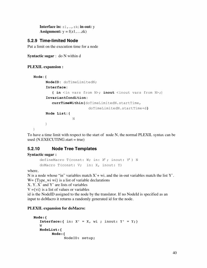
Interface in: z1,…,zk; in-out: y Assignment: y = f(z1,…,zk)
5.2.9 Time-limited Node Put a limit on the execution time for a node Syntactic sugar : do N within d
PLEXIL expansion :
Node:{ NodeID: doTimeLimitedN; Interface: { in <in vars from N>; inout <inout vars from N>;}
InvariantCondition: currTimeWithin{doTimeLimitedN.startTime, doTimeLimitedN.startTime+d}
Node List:{ N
}
}
To have a time limit with respect to the start of node N, the normal PLEXIL syntax can be used (N.EXECUTING.start = true)
5.2.10 Node Tree Templates Syntactic sugar :
defineMacro T(const: W; in: X’; inout: Y’) N
doMacro T(const: V; in: X, inout: Y)
where, N is a node whose “in” variables match X’+ wi, and the in-out variables match the list Y’. W= {Type_wi wi} is a list of variable declarations X, Y, X’ and Y’ are lists of variables V ={vi} is a list of values or variables id is the NodeID assigned to the node by the translator. If no NodeId is specified as an input to doMacro it returns a randomly generated id for the node. PLEXIL expansion for doMacro:
Node:{ Interface:{ in: X’ = X, wi ; inout: Y’ = Y;} W NodeList:{
Node:{ NodeID: setup;

41
Interface:{ in <vars in V>; inout: wi;} Assignment: each vi to wi; /* This may be a sequence of assignments*/ Node:{ NodeID: doN; Interface:{ in: X’, wi; inout: Y’;} StartCondition: setup.state==FINISHED; NodeList:{ N } } } }
T is just a name, and the N in doMacro corresponds to the N in the corresponding defineMacro.
5.2.11 Absolute and Relative Time Syntactic Sugar:
AbsoluteTimeWithin : { LowerBound, UpperBound, Frequency }
PLEXIL Expansion: lookupWithFrequency { “time” , Frequency} >= LowerBound & lookup{“time”, Frequency} <= UpperBound Syntactic Sugar:
CurrentTimeWithin : { NodeTimepointValue + [ LowerBound, UpperBound ], Frequency}
PLEXIL Expansion: lookupWithFrequency { “time”, Frequency } >= NodeTimepointValue + LowerBound & lookupWithFrequency{“time”, Frequency} <= NodeTimepointValue + UpperBound where, LowerBound and UpperBound are Time values, or variables representing time. If Frequency is not specified in the syntactic sugar, it defaults to 10.
5.2.12 Examples
5.2.12.1 Red-rock Example Simplified with Syntactic Enhancements
The red rock example from 4.1.1 and 4.1.2 can be re-written as follows using syntax extensions:
Node:{ NodeID: DriveRRorDist4; Boolean haveRR=false, stop=false, goalDist=false; NodeList:{
42
doMacro ContDrive(in: stop) when lookupWithFrequency("found RR", 10)==true
assign haveRR=true when lookupWithFrequency("Rover:distTravelled", 10)==10m
assign goalDist=true when haveRR==true | goalDist==true
assign stop = true }
}
The macro definition used above is as follows:
defineMacro ContDrive(:in stop) NodeList:{ Node:{ NodeID: StartDrive;
Command: "Rover:drive"; }
Node:{ NodeID: StopDrive; Interface:{ in stop;} StartCondition: stop && startDrive.state == FINISHED; Command: "Rover:stop"; } }
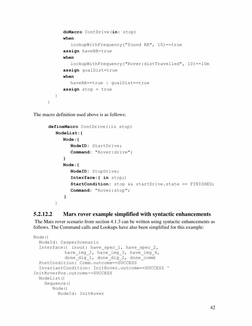
5.2.12.2 Mars rover example simplified with syntactic enhancements The Mars rover scenario from section 4.1.3 can be written using syntactic enhancements as follows. The Command calls and Lookups have also been simplified for this example: Node:{ NodeId: CasperScenario Interface:{ inout: have_spec_1, have_spec_2, have_img_2, have_img_3, have_img_4, done_dig_1, done_dig_2, done_comm} PostCondition: Comm.outcome==SUCCESS InvariantCondition: InitRover.outcome==SUCCESS ^ InitRoverPos.outcome==SUCCESS NodeList:{ Sequence:{ Node:{ NodeId: InitRover
43
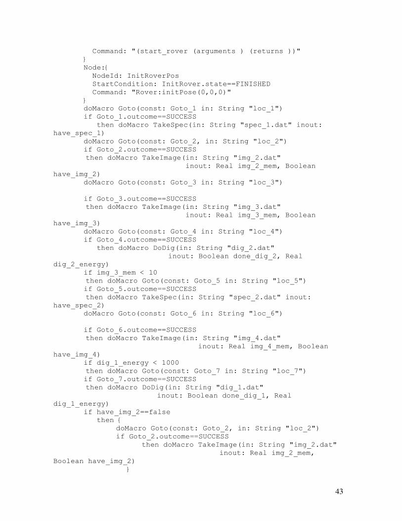
Command: "(start_rover (arguments ) (returns ))" } Node:{ NodeId: InitRoverPos StartCondition: InitRover.state==FINISHED Command: "Rover:initPose(0,0,0)" } doMacro Goto(const: Goto_1 in: String "loc_1") if Goto_1.outcome==SUCCESS then doMacro TakeSpec(in: String "spec_1.dat" inout: have_spec_1) doMacro Goto(const: Goto_2, in: String "loc_2") if Goto_2.outcome==SUCCESS then doMacro TakeImage(in: String "img_2.dat" inout: Real img_2_mem, Boolean have_img_2) doMacro Goto(const: Goto_3 in: String "loc_3") if Goto_3.outcome==SUCCESS then doMacro TakeImage(in: String "img_3.dat" inout: Real img_3_mem, Boolean have_img_3) doMacro Goto(const: Goto_4 in: String "loc_4") if Goto_4.outcome==SUCCESS then doMacro DoDig(in: String "dig_2.dat" inout: Boolean done_dig_2, Real dig_2_energy) if img_3_mem < 10 then doMacro Goto(const: Goto_5 in: String "loc_5") if Goto_5.outcome==SUCCESS then doMacro TakeSpec(in: String "spec_2.dat" inout: have_spec_2) doMacro Goto(const: Goto_6 in: String "loc_6") if Goto_6.outcome==SUCCESS then doMacro TakeImage(in: String "img_4.dat" inout: Real img_4_mem, Boolean have_img_4) if dig_1_energy < 1000 then doMacro Goto(const: Goto_7 in: String "loc_7") if Goto_7.outcome==SUCCESS then doMacro DoDig(in: String "dig_1.dat" inout: Boolean done_dig_1, Real dig_1_energy) if have_img_2==false then { doMacro Goto(const: Goto_2, in: String "loc_2") if Goto_2.outcome==SUCCESS then doMacro TakeImage(in: String "img_2.dat" inout: Real img_2_mem, Boolean have_img_2) }

44
Node: { NodeId: Comm StartCondition: AbsoluteTimeWithin(1800, 2000, 10) InvariantCondition: AbsoluteTimeWithin(1800, 2000, 10) Command: "Rover:Comm" } } } } } defineMacro Turn_to(NodeId: id in: location, start_time, end_time) :{ Node:{ InvariantCondition: LookupOnce("currentTime")+LookupOnChange:{"Navigator:estimatedTimeToGoal"} > end_time PostCondition: LookupNow:{"Rover:position"}==location Command: "Navigator:turn(location)" } } defineMacro Goto(NodeId: id in: location, start_time, end_time) :{ Sequence:{ doMacro Turn_to(location); Node:{ InvariantCondition: LookupOnce("currentTime")+LookupOnChange:{"Navigator:estimatedTimeToGoal"} > end_time PostCondition: LookupNow:{"Rover:position"}==location Command: "Navigator:drive(location)" } } } defineMacro Spec(NodeId:id in: String datafile) :{ Node:{ Command: "Rover:take_spectrometer_reading(datafile)" } } defineMacro TakeSpec(in: String datafile inout: Boolean have_spec) :{ Sequence: { id = doMacro Spec(in: String datafile) if id.outcome==SUCCESS assign have_spec=true } }

45
defineMacro Image(NodeId:id in: String datafile inout: Real memoryUsed) :{ Node:{ Command: memoryUsed="Rover:take_picture(datafile)" } } defineMacro TakeImage(in: String datafile inout: Real img_mem, Boolean have_img) :{ Sequence: { id = doMacro Image(in: String datafile inout: Real img_mem) if id.outcome==SUCCESS assign have_img=true } } defineMacro Dig(NodeId:id in: String datafile inout: energy_used) :{ Node:{ Command: energy_used="Arm:dig(datafile)" } } defineMacro DoDig(in: String datafile inout: Boolean done_dig, Real energy_used) :{ Sequence: { id = doMacro Dig(in: String datafile, inout energy_used) if id.outcome==SUCCESS assign done_dig=true } }

46
Appendix A: PLEXIL Context Free Grammar Notation used: ? denotes optional * denotes 0 or many elements | denotes alternates ; added at the end of each grammar production “” defined keywords in the language As a general rule “<language element>{” … “}” denotes the start and end of that language element. All caps represents built-in XML types, e.g. STRING, INTEGER… /* PLEXIL grammar: "{" "}" used only for Node, NodeList, VarDecl, In and InOut pre-defined types/values: string, nonNegativeInteger, boolean, integer, double, INF, -INF */ PlexilPlan : Node ; Node : (NodeId ":")? "{" NodeAttributes? NodeBody? "}"; NodeId : string ; NodeBody : NodeList | Command | Assignment ; NodeList : "NodeList" ":" "{" Node* "}" ; NodeAttributes : /* here the xml schema specifies any order */ StartCondition? RepeatUntilCondition? PreCondition? PostCondition? InvariantCondition? EndCondition? Priority? Interface? VariableDeclarations? ; Priority : "Priority" ":" nonNegativeInteger ";" ; StartCondition : "StartCondition" ":" BooleanExpression ";" ; RepeatUntilCondition : "RepeatUntilCondition" ":" BooleanExpression ";" ; PreCondition : "PreCondition" ":" BooleanExpression ";" ; PostCondition : "PostCondition" ":" BooleanExpression ";" ; InvariantCondition : "InvariantCondition" ":" BooleanExpression ";" ; EndCondition : "EndCondition" ":" BooleanExpression ";" ; Interface : /* here the xml schema specifies any order */ In? InOut? ; In : "In" ":" "{" (DeclaredVariable ";" )* "}" ;

47
InOut : "InOut" ":" (DeclaredVariable ";" )* "}" ; DeclaredVariable : IntegerVariable | RealVariable | BooleanVariable | StringVariable | PointerVariable ; IntegerVariable : NCName ; RealVariable : NCName ; BooleanVariable : NCName ; StringVariable : NCName ; PointerVariable : NCName ; VariableDeclarations : ( VariableDeclaration )* ; VariableDeclaration : ( "Boolean" ":" "{" (BooleanVariable ("=" BooleanValue)? ";" )* "}" ) | ( "Integer" ":" "{" (IntegerVariable ("=" IntegerValue)? ";" )* "}" ) | ( "Real" ":" "{" (RealVariable ("=" RealValue)? ";" )* "}" ) | ( "String" ":" "{" (StringVariable ("=" StringValue)? ";" )* "}" ) | ( "Pointer" ":" "{" (PointerVariable ("=" PointsTo)? ";" )* "}" ) ; BooleanValue : boolean | "UNKNOWN" ; IntegerValue : integer | "UNKNOWN" ; RealValue : double | "UNKNOWN" ; StringValue : string | "UNKNOWN" ; PointsTo : ExternalStructName InitialValue? ; ExternalStructName : string ; InitialValue : integer ; Command : "Command" ":" (DeclaredVariable "=")? CommandName "(" Arguments? ")" ";"; Arguments : ((IntegerValue | RealValue | BooleanValue | DeclaredVariable ) ";"? )* ; Assignment : "Assignment" ":" (BooleanAssignment | NumericAssignment) ; BooleanAssignment : BooleanVariable "=" BooleanRHS ";"; NumericAssignment : ( IntegerVariable | RealVariable ) "=" NumericRHS ";"; BooleanRHS : BooleanExpression ; NumericRHS : NumericExpression ; BooleanExpression : OR | AND | NOT | GT | GE | LT | LE | EQ | NE | BoleanVariable | BooleanValue | Lookup | "(" BooleanExpression ")" ; OR : "OR" ( BooleanExpression )+ ; AND : "AND" ( BooleanExpression)+ ; NOT : "NOT" BooleanExpression ; GT : NumericExpression ">" NumericExpression ; GE : NumericExpression ">=" NumericExpression ; LT : NumericExpression "<" NumericExpression ; LE : NumericExpression "<=" NumericExpression ; EQ : EQBoolean | EQNumeric | EQInternal ; EQBoolean : BooleanExpression "==" BooleanExpression ; EQNumeric : NumericExpression "==" NumericExpression ;

48
EQInternal : NodeState "==" NodeState | NodeOutcome "==" NodeOutcome ; NEExpression : NEBoolean | NENumeric | NEInternal ; NEBoolean : BooleanExpression "!=" BooleanExpression ; NENumeric : NumericExpression "!=" NumericExpression ; NEInternal : NodeState "!=" NodeState | NodeOutcome "!=" NodeOutcome ; NodeState : NodeStateVariable | NodeStateValue ; NodeStateVariable : NodeId".state" ; NodeStateValue : "WAITING" | "EXECUTING" | "FINISHING" | "FAILING" | "FINISHED" ; NodeOutcome : NodeOutcomeVariable | NodeOutcomeValue ; NodeOutcomeVariable : NodeId".outcome" ; NodeOutcomeValue : "SUCCESS" | "FAILURE" | "SKIPPED" | "INFINITE_LOOP"; NodeTimepointValue : NodeId"."NodeStateValue"."Timepoint ; Timepoint : "START" | "END" ; NumericExpression : ADD | SUB | MUL | DIV | IntegerVariable | RealVariable | IntegerValue | RealValue | Lookup | NodeTimepointValue | PlusInfinity | MinusInfinity | "(" NumericExpression ")" ; PlusInfinity : "INF" ; MinusInfinity : "-INF" ; ADD : NumericExpression "+" NumericExpression ; SUB : NumericExpression "-" NumericExpression ; MUL : NumericExpression "*" NumericExpression ; DIV : NumericExpression "/" NumericExpression ; Lookup : LookupWithFrequency | LookupOnChange | LookupNow ; LookupWithFrequency : "LookupWithFrequency" ":" StateName "," Parameter* "," Frequency ";" ; StateName : string ; Frequency : RealValue | DeclaredVariable ; LookupOnChange : "LookupOnChange" ":" StateName "," Parameter* ("," Tolerance)? ";" ; Tolerance : Value | DeclaredVariable ; LookupNow : "LookupNow" ":" StateName ";" ; Parameter: string ;

49
Appendix B: Automated Verification for PLEXIL PLEXIL is designed to be easily verifiable. A future proposal is to use a combination of formal methods and advanced testing techniques to provide automated support for the design and verification of the PLEXIL language and execution system. The verification effort will be performed at several levels: – Plan verification. Our goal is to design the PLEXIL language to facilitate verification
and to build tools that automate the verification of plans written in the PLEXIL language. We have already worked towards designing the language to facilitate verification. For example, the current definition of the PLEXIL language requires explicit interfaces between execution nodes, which facilitate checking that typed variables are used properly (e.g. a node can not do an assignment to an “in” variable). We also plan to build a tool that will check key properties for PLEXIL plans. The idea is to check that plan properties are met before executing the plan. For example, we can check that temporal constraints between execution nodes don’t introduce deadlock or that all the node conditions are satisfiable (hence all the nodes can potentially execute). We will use model checking technology for automated plan verification. We are working on an automatic translation from XML PLEXIL plans into a Java representation (using the Castor tool, which translates XML schemas into Java code), and to use the Java PathFinder model checking tool developed at Ames to check properties of the translated plans. Java PathFinder analyzes all the features of Java; in addition it uses decision procedures to handle numeric constraints. We plan to use the plan verification tool in conjunction with the user interface developed on top of Maestro - the idea is that the user will create or modify a PLEXIL plan and will use our tool to validate the plan, before sending it to the executive.
– Automated test plan generation. Another direction for work is to develop a tool for automated generation of test plans, written in PLEXIL. We will build upon our previous work on plan generation for the CRL Exec (for the K9 rover developed at Ames), where we developed a tool that generates hundreds of complex plans in a few seconds. Our approach will use specification-based testing techniques, where the specification is the PLEXIL grammar. We will use symbolic execution techniques to deal with the time/data constraints in plans. The generated plans will be used to test the PLEXIL execution system and the various PLEXIL translators that will be developed in the later phases of the project.

50
Appendix C: PLEXIL Plan Editor A graphical editor for viewing and editing task plans specified in the PLEXIL Language is currently being prototyped at IA Tech, Inc. The PLEXIL Plan Editor (PPE) is developed as a component under the Ensemble architecture and implemented on top of the Eclipse Platform.
C.1 The Ensemble Platform Ensemble is an open architecture for the development, integration, and deployment of mission operations software. It is a collaboration effort shared by multiple teams from multiple NASA centers, including the Jet Propulsion Laboratory (JPL) and Ames Research Center, with the objective of bringing a diverse set of NASA mission operations tools into a common framework based on the Eclipse Platform. Currently, JPL is developing Maestro based on the Mars Exploration Rover (MER) Science Activity Planner (SAP) and Ames is developing SPIFe based on the MER Constraint Editor and MAPGEN software. It is expected that many other NASA ground-based mission operations tools will be migrated to the Ensemble architecture in the future. Developing the PLEXIL Plan Editor under the Ensemble architecture provides the advantage of leveraging other Ensemble components when creating a PLEXIL plan. For example, the user can use various Ensemble image viewers to visualize the terrains and designate targets. The locations of the targets can then be used as parameters in the plan. We also envision that the PLEXIL plan can be tied to SPIFe so that it can provide a timeline view and a constraint editor to the plan. The Ensemble architecture is based heavily upon the tools and technologies of the Eclipse Platform. Eclipse is an open source software development project providing a universal platform for integrating development tools. At the core of Eclipse is an architecture for dynamic discovery, loading, and running of plug-ins. The platform handles the logistics of finding and running the right code. Each plug-in can then focus on doing a small number of tasks well. The Ensemble components are developed as plug-ins on the Eclipse Platform. The plug-ins are then used to build customized operations tools, such as Maestro, using the Eclipse Rich Client Platform. In addition to the Eclipse Platform, the Eclipse Project also provides a full-featured integrated development environment (IDE). The IDE consists of a set of Java Development Tools (JDT) and the Plug-in Development Environment (PDE)

51
C.2 The Plexil Plan Editor The PLEXIL Plan Editor allows the user to create a PLEXIL plan by adding different types of nodes to the editing area, connecting the child nodes to the node-list nodes, and specifying attributes and actions of each node. Plan editing functions that have been implemented include selecting, deleting, moving, resizing, and reconnecting the nodes. All editing actions can be undone and redone an unlimited number of times. When a node is selected, its attribute and action fields are displayed and can be edited in the Property Sheet. For the initial prototype, all the fields are entered as text strings. The PLEXIL Plan Editor is implemented based on the model-view-controller (MVC) pattern of the Eclipse Graphical Editing Framework (GEF). C.2.1 The Model The first step of building the PPE is to create a model of the PLEXIL plan. The model stores all data that may be edited or viewed by the user. That means besides the pertinent data relevant to a PLEXIL plan, the model also includes data for visual representation, such as the position and size of each node. The model is composed of Java objects of various classes. We first define a base Node class which contains the common attributes of the three types of PLEXIL nodes. We then define the ListNode, CommandNode, and AssignmentNode classes by extending the base Node class with additional action fields. In addition to the node classes, the model also includes the Plan class which contains an array of all the nodes in the plan, and the Connection class which contains the source and target node of the connection. The model also provides ways for 1) persistence such that the model can restore its state from permanent storage, and 2) other objects to listen to changes in the model. A super class ModelElement is implemented to provide these two functionalities. C.2.2 The Views
We use predefined figures provided by Draw2D to represent our model. The Plan is represented by the Figure class equipped with the FreeformLayout manager. This gives the user the freedom to drag and drop nodes at any location. Node-List nodes are represented by Ellipse and action nodes by RectangleFigure. To distinguish the two types of action nodes, Command nodes are colored yellow while the Assignment nodes are colored green. Each node is also labeled with its NodeID. The figure is updated whenever the NodeID is changed. The connection linking a Node-List node to its child node is represented by a polyline decorated with an arrow. C.2.3 The Controllers For each element of the model, we define a controller so that the element can be manipulated by the user. The role of the controllers (or edit parts in GEF terminology) is to understand the model, listen to events about its changes, and update views correspondingly.
52
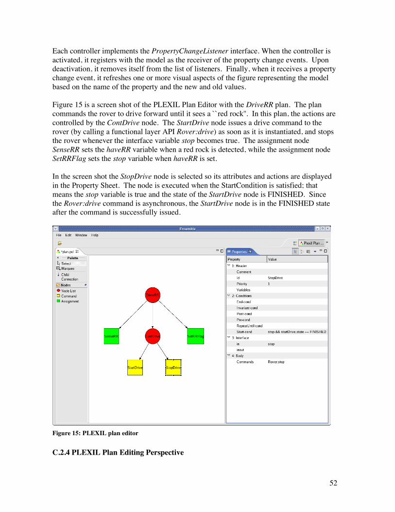
Each controller implements the PropertyChangeListener interface. When the controller is activated, it registers with the model as the receiver of the property change events. Upon deactivation, it removes itself from the list of listeners. Finally, when it receives a property change event, it refreshes one or more visual aspects of the figure representing the model based on the name of the property and the new and old values. Figure 15 is a screen shot of the PLEXIL Plan Editor with the DriveRR plan. The plan commands the rover to drive forward until it sees a ``red rock''. In this plan, the actions are controlled by the ContDrive node. The StartDrive node issues a drive command to the rover (by calling a functional layer API Rover:drive) as soon as it is instantiated, and stops the rover whenever the interface variable stop becomes true. The assignment node SenseRR sets the haveRR variable when a red rock is detected, while the assignment node SetRRFlag sets the stop variable when haveRR is set. In the screen shot the StopDrive node is selected so its attributes and actions are displayed in the Property Sheet. The node is executed when the StartCondition is satisfied; that means the stop variable is true and the state of the StartDrive node is FINISHED. Since the Rover:drive command is asynchronous, the StartDrive node is in the FINISHED state after the command is successfully issued.
Figure 15: PLEXIL plan editor
C.2.4 PLEXIL Plan Editing Perspective

53
A PLEXIL Plan Editing perspective is implemented to facilitate the use of the editor. In Eclipse, a perspective is a stacked, tiled, or detached arrangement of views and editors. In the PLEXIL perspective, we place the Editor to the left of the workbench and the Property Sheet to the right. The perspective is added to Ensemble so that when the user selects this perspective the workbench will only show the view and editor that are relevant for editing a PLEXIL plan. C.2.5 PLEXIL Plan Editing Actions Two actions are implemented and they are added to the menu of the Ensemble workbench when the PLEXIL Plan Editing Perspective is selected. The OpenPlanAction is used to open an existing plan file saved in the workspace. The ExportPlanAction is used to export the plan to a file containing its PLEXIL XML representation. Below is the XML5 representation of the DriveRR plan. <?xml version="1.0" encoding="UTF-8"?> <Node xmlns:xsi="http://www.w3.org/2001/XMLSchema-instance" xsi:noNamespaceSchemaLocation="schema/plexil.xsd"> <NodeAttributes> <NodeID>DriveRR</NodeID> <Comment>Drive Rover to Red Rock</Comment> <Priority>1</Priority> <Variables>Bool haveRR = false; stop = false</Variables> </NodeAttributes> <NodeBody> <Node> <NodeAttributes> <NodeID>ContDrive</NodeID> <Priority>1</Priority> <Interface>in stop</Interface> </NodeAttributes> <NodeBody> <Node> <NodeAttributes> <NodeID>StartDrive</NodeID> <Priority>1</Priority> </NodeAttributes> <NodeBody> <Commands>Rover:drive</Commands> </NodeBody> </Node> <Node> <NodeAttributes> <NodeID>StopDrive</NodeID> <StartCondition>stop && startDrive.state == FINISHED</Start-Condition> <Priority>1</Priority> <Interface>in stop</Interface> </NodeAttributes>
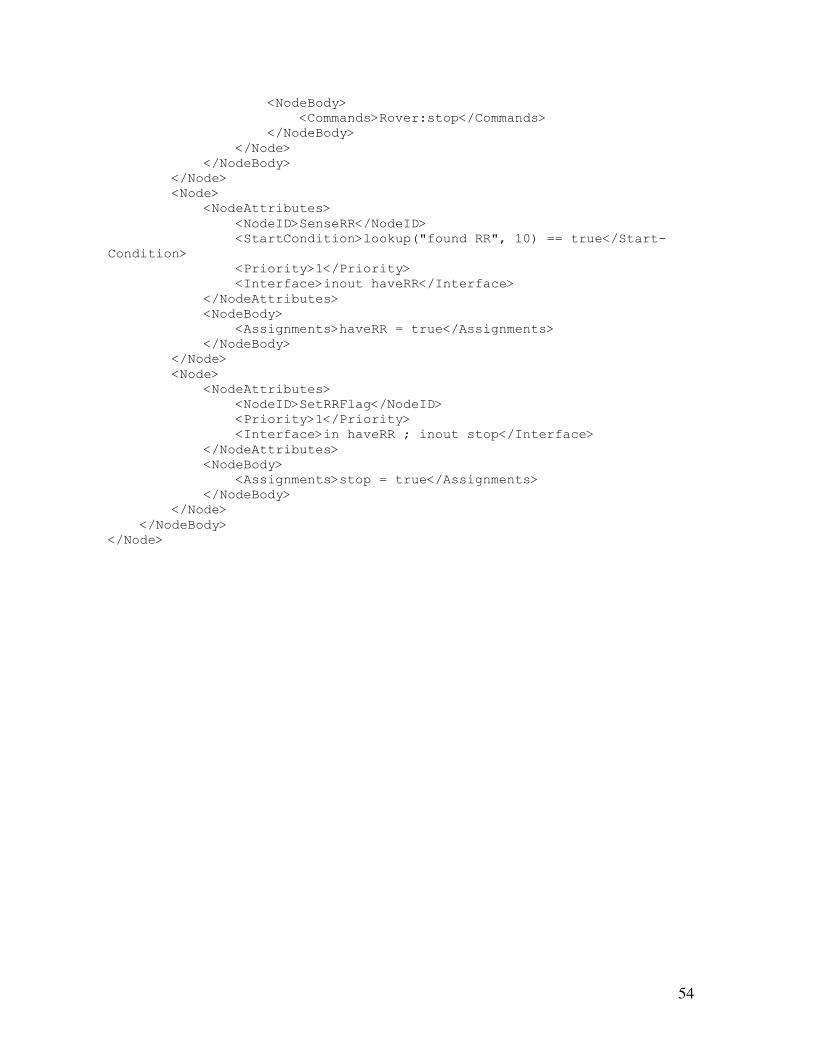
54
<NodeBody> <Commands>Rover:stop</Commands> </NodeBody> </Node> </NodeBody> </Node> <Node> <NodeAttributes> <NodeID>SenseRR</NodeID> <StartCondition>lookup("found RR", 10) == true</Start-Condition> <Priority>1</Priority> <Interface>inout haveRR</Interface> </NodeAttributes> <NodeBody> <Assignments>haveRR = true</Assignments> </NodeBody> </Node> <Node> <NodeAttributes> <NodeID>SetRRFlag</NodeID> <Priority>1</Priority> <Interface>in haveRR ; inout stop</Interface> </NodeAttributes> <NodeBody> <Assignments>stop = true</Assignments> </NodeBody> </Node> </NodeBody> </Node>

55
Appendix D: Compete Set of Node State Transitions Node state transitions are affected by only a small subset of condition changes either in self (the node itself) or an ancestor or descendant of the node. The table below presents the complete set of transitions:
Node B relation to Node
A
Current State of Node B
Node A -
Start Condition T
Node A - End
Condition T
Node A - Invariant
Condition F
Node A - Command Abort Done Notes
Self Waiting TD_Wa
iting
End + invariant have no impact on waiting node
Self - List Executing TD_Exec_L
istNode TD_Exec_Lis
tNode Start cond has no effect during exec
Self - Cmd Executing
TD_Exec_CmdNode
TD_Exec_CmdNode
Start cond has no effect during exec
Self - Assign Executing
TD_Exec_AssignNode
TD_Exec_AssignNode
Start cond has no effect during exec
Self Finishing TD_Finishing
Start or end condition irrelevant once node in finishing state
Self Failing
Start, end or invariant condition irrelevant once node in failing state
Self Cmd_Faili
ng TD_Exec_
Cmd
Start or end condition irrelevant and invarient yields no change
Self Finished Nothing happens once a node is finished
Descendent Waiting
TD_Waiting TD_Waiting
Only end or invariant failure of ancestor can affect a waiting node
Descendent - List Executing
TD_Exec_ListNode
Ancestor end condition has no affect on node already executing, finishing or failing
Descendent - Cmd Executing
TD_Exec_CmdNode
Ancestor end condition has no affect on node already executing, finishing or failing
Descendent -
Assign Executing TD_Exec_As
signNode
Ancestor end condition has no affect on node already executing, finishing or failing

56
Descendent Finishing TD_Finishing
Ancestor end condition has no affect on node already executing, finishing or failing
Descendent Failing TD_Failing
Ancestor failure changes handling of a failing descendent (no repeat, diff outcome)
Descendent
Cmd_Failing
Cannot happen - commands have no descendents
Descendent Finished
Nothing happens once a node is finished
Ancestor Waiting
Cannot happen - a waiting node has no descendents waiting for state changes
Ancestor Executing TD_Exec_L
istNode TD_Exec_Lis
tNode TD_Exec_ListNode
Ancestor can only be list - may be waiting for descendent to complete execution
Ancestor Finishing TD_Finishi
ng TD_Finishing TD_Finishi
ng
Ancestor may be waiting for descendent to complete execution
Ancestor Failing TD_Failing TD_Failing TD_Failin
g
Ancestor may be waiting for descendent to complete execution - so have to check
Ancestor Cmd_Faili
ng
Cannot happen - an ancestor cannot be a command
Ancestor Finished Nothing happens once a node is finished
• Transition diagram for state Waiting (TD_Waiting) is shown in Figure 6 • Transition diagram for NodeList in state Executing (TD_Exec_ListNode) is shown
in Figure 7 • Transition diagram for an Assignment node in state Executing
(TD_Exec_Assignment) is shown in Figure 8 • Transition diagram for a Command node in state Executing is shown in
(TD_EXEC_CmdNode) is shown in Figure 9 • Transition diagram for state Finishing (TD_Finishing) is shown in Figure 10 • Transition diagram for state Failing (TD_Failing) is shown in Figure 12