planar e cores - elnamagnetics.com · the power ferrite for a high permeability grade. in pulse...
TRANSCRIPT

Planar E Cores
Application NotePhilips Magnetic Products
PhilipsComponents

Philips Magnetic Products
1
Contents
1. Introduction 32. Advantages of planar technology 4
2.a. Design advantages 42.b. Manufacturing advantages 42.c. Limitations 52.d. Integrated versus stand-alone 52.e. Gluing versus clamping 6
3. Applications 63.a. Power conversion 63.b. Pulse transmission 6
4. Product range 74.a. Material grades 74.b. Cores for gluing 84.c. Cores for clamping 124.d. Packing 16
5. Design 185.a. Core choice 185.b. Winding design 18
6. Manufacturing 196.a. Assembly 196.b. Mounting 196.c. Soldering 19
7. Literature & sample boxes 208. Type number system 20
Planar E Cores
Philips Magnetic Products
2
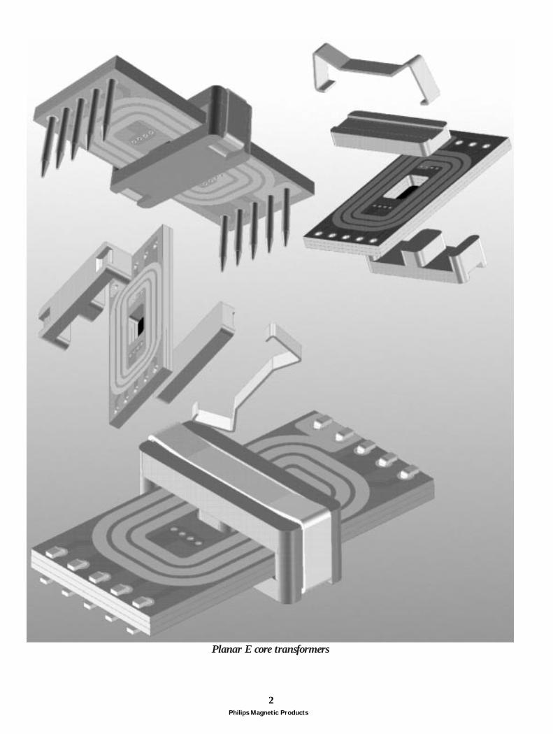
Planar E core transformers

Philips Magnetic Products
3
1.IntroductionPlanar magnetics offer an attractive alternative toconventional core shapes when low profile magnetic devicesare required. Basically this is a construction method ofinductive components with windings made of printedcircuit tracks or copper stampings separated by insulatingsheets or constructed with multi-layer circuit boards. Thesewindings are placed between low-profile ferrite cores.Planar devices can be constructed in several ways. Theclosest to conventional devices is a stand-alone componentto replace components on a mono-layer or any other circuitboard. The height of a stand-alone component can bereduced by sinking the core through a slot in the motherboard until its windings rest on the mother board. Onestep further is a hybrid type, where part of the windings arein the mother board while others are joined as a separatemulti-layer circuit board. The mother board must haveslots cut out to accept the ferrite core. The last version isachieved by total integration in a multi-layer mother board.
Just like for wire-wound components, the core halves canbe assembled either by gluing or by clamping, dependingon the capabilities and preferences of the manufacturer.Philips Components manufacture a range of planar E cores,which is presented in this brochure. In addition, a wholerange of low profile RM cores is available. For moreinformation, please consult our DATA HANDBOOKMA01 or Product Selection Guide.
integrated
stand-alone
stand-alone sunken
hybrid
Fig.1 Several types of planar devices

Philips Magnetic Products
4
2.Advantages of planar technologyThere are many advantages of planar magnetic technologyover conventional wire-wound inductive components.An obvious advantage is a very low build height, whichpromotes planar in dense rack-mount and portableequipment.
Planar magnetics are very well suited for design of highperformance switch-mode power converters. Low ACcopper losses and good coupling increase conversionefficiency. Levels higher than 95 % can be achieved,provided that the core is ungapped or only has a moderateair gap. In addition, low leakage inductance reduces voltagespikes and oscillations that can damage MOSFETs andincrease interference emission.
2.a. Design advantagesFeature stand-alone Integrated• Mechanical characteristics
Very low profile x x x
Compact and rigid construction x x x
• Electrical characteristics
Little skin and proximity effect in flat copper tracks x x
Good coupling of closely stacked transformer windings x x x
Excellent repeatability due to fixed winding layout x x
• Heat management
High core surface (cooling) to volume (dissipation) ratio x x
Compact coil with good heat conduction x x
Large core surface for heat sink contact x x
Good heat management leads to very high throughputpower density, up to twice the value for conventionaltransformers. Very good repeatability of parasitics enableshigh switching frequencies and resonant topologies. Coresare available in material 3F4 for switching frequencies up to3 MHz.
Planar technology is straight forward and reliable inproduction. Advantages and limitations are listed infollowing tables.
2.b. Manufacturing advantagesFeature stand-alone Integrated• Forward integration
No coil former required x x
No separate windings required x
No pinning / leads required x
Independence of component assembler x
• Manufacturability
No winding operation x x
No soldering operation x
Compatible with SMD technology x x
• Reliability
No winding errors / short circuit x x
No solder contact problems x

Philips Magnetic Products
5
2.c. LimitationsFeature Stand-alone Integrated• General
Only if multi-layer mother board x
Cost of planar windings versus copper wire (1) x
Design & production knowledge needed by board assembler x
Every design needs its own prefab winding x x x
• Design
Low copper cross-section to window area ratio x x x
Parasitic capacitance limits winding design possibilities x x x
Designs with large air gap are unfavourable x x
• Manufacturing
The batch to batch spread can’t be compensated with the turns x x
Sunken stand-alone components reduce the build heightwithout changing component layout. Hybrid components make use of the mother board tracksto reduce the number of stand-alone tracks, whereas theseare completely eliminated with an integrated component.Combinations of the foregoing types are also possible. Forexample, a power converter could have the primarywinding and mains filter choke (fixed) in the mother boardand the secondary winding and output choke (custom) instand-alone PCB’s (see Fig. 2).
2.d.Integrated versus stand-aloneIntegrated planar components are used if the complexity ofthe surrounding circuitry already demands for multi-layerPCB. Typical applications can be found in low powerconversion and signal processing and use mostly E / platecombination of the small sizes. Main design considerationsfor planar here are flatness and high frequency electricalcharacteristics.Stand-alone components are used otherwise. Typicalapplications can be found in high power conversion anduse mostly E / E combination of the large sizes. Maindesign consideration for planar here is heat management.The type of windings depends partly on the current rating. Low : multi-layer PCB (most compact) or stacked
mono-layer PCB (standard windings)Medium : stacked flex foil leadframes (thick tracks) or
ceramic substrates (good heat conduction)High : self-supporting leadframes (nut & bolt type)
Note (1) The price of multi-layer PCB is coming down. Overall cost : no coil former and smaller core.
transformer primarymains filter choke
output choketransformer secondary
Fig.2 Hybrid design with planar magnetics.

Philips Magnetic Products
6
2.e.Gluing versus clampingThe choice between gluing and clamping depends mainlyon the capabilities and preferences of the manufacturer, butalso the application requirements can favour one of thetwo.
•• Reasons for gluingSimple production automationUniform core cross-section (saturation)Low build height (no clamp arc)Smaller PCB cut-out (integrated version)Fixation of cores to the PCB (no rattle/noise)
•• Reasons for clampingClean assembly processNo environmental influence on assembly processNo problems in high temperature applicationNo increase of parasitic gap (high permeability)
3.ApplicationsThe first applications for planar E cores were in powerconversion. Correspondingly, material grades weremedium and high frequency power ferrites. The inductanceof the mains filter choke can be increased by substitutingthe power ferrite for a high permeability grade. In pulsetransmission, a wideband transformer between pulsegenerating IC and cable provides isolation and impedancematching. For an S or T-interface, this should also be ahigh permeability ferrite. Cores in the high permeabilitymaterial 3E6 have been added to our range. A listing ofapplications, likely to profit from planar, is given below.
3.a.Power conversion• Components
power transformer, output or resonant choke(s), mains filter choke
• AC/DC converter (mains-fed power supply)Stand-alone SMPSBattery charger (mobile phone, portable computers)Instrumentation & control
• DC/DC converter (distributed or battery-fed power supply)Power converter modulesTelecommunications network switch (distributed supply)Mobile phone (main power supply)Portable computer (main power supply)Electric car (traction voltage to 12 V down converter)
• AC/AC converter (mains-fed power supply)Compact fluorescent lampsInduction heating, welding
• DC/AC inverter (battery-fed power supply)Mobile phone (LCD backlighting)Portable computer (LCD backlighting)Gas discharge car headlamp (ballast)Car rear window heating (step-up converter)
3.b.Pulse transmission• Component
wideband transformerS0 interface (subscriber telephone line)U interface (subscriber ISDN line)T1/T2 interface (trunk line between network switches)ADSL interface (Asynchronous Digital Subscriber Line)HDSL interface (High Digital Subscriber Line)

Philips Magnetic Products
7
4.Product rangePhilips Components offer an extensive product range ofplanar E cores. Sizes range from 14 to 64 mm. The cross-sectional area is always uniform for the basic version forgluing to make optimum use of the ferrite volume. Everysize has an E core and corresponding plate (PLT). A coreset consists of either an E core and a plate or two E cores,in which case the winding window height doubles. Thesmallest 3 sizes also have an E/PLT version for clamping.The E core has recesses (E/R) while the plate has a slot(PLT/S). A clamp (CLM) snaps into the recesses andprovides a firm grip, pressing the plate on two points. Theslot prohibits the plate from sliding out even in case ofstrong shocks or vibrations and provides alignment. For theE / E combination there are no clips.All sizes are available in power materials 3F3 (frequencies
up to 500 kHz) and 3F4 (500 kHz - 3 MHz). The largest5 sizes are also available in 3C85 (frequencies up to 200kHz), as large cores are often used in low frequency, highpower applications. The smallest 3 sizes are available inhigh permeability 3E6 (µi12000) as well for mains filter chokes and wideband transformers.
All E cores in power materials can be gapped, preferably ina standard range of AL values. Every AL value correspondsto 2 slightly different gaps, depending on whether themating part is another E core or a plate (P). Default isasymmetric gap (A) ; the mating part is a plate or anungapped E core. The largest 5 sizes have their largest gapssymmetrical (E) ; the mating part is an identical gapped Ecore.
For an overview of the type number system : see section 8.
Initial permeability µi - f = ≤10 kHz, B < 0.1mT, 2000 1800 900 12000T = 25 oC
Saturation flux density Bs mT f = 10 kHz, T = 25 oC ≈500 ≈500 ≈450 ≈400at Field strength H A/m 3000 3000 3000 250Remanence Br mT T = 25 oC ≈160 ≈150 ≈150 ≈100
Coercivity Hc A/m T = 25 oC ≈15 ≈15 ≈60 ≈4
Power loss density Pv kW/m3 f = 25kHz, B = 200mT, T = 100 oC 100 70 - -(typical, sinewave f = 100kHz, B = 100mT, T = 100 oC 120 50 200 -excitation) f = 500kHz, B = 50mT, T = 100 oC - 180 180 -
f = 1MHz, B = 30mT, T = 100 oC - 300 140 -f = 3MHz, B = 10mT, T = 100 oC - - 240 -
Curie temperature TcoC - ≥200 ≥200 ≥220 ≥130
Resistivity (DC) ρ Ωm T = 25 oC ≈2 ≈2 ≈10 ≈0.5Density g/cm3 T = 25 oC ≈4.8 ≈4.8 ≈4.7 ≈4.9
PARAMETER SYMBOL UNIT TEST CONDITIONS 3C85 3F3 3F4 3E6
4.a.Material grades

Philips Magnetic Products
8
E14/3.5/5(E-E combination)
PLT14/5/1.5(E-PLT combination)
E18/4/10(E-E combination)
PLT18/10/2(E-PLT combination)
E22/6/16(E-E combination)
PLT22/16/2.5(E-PLT combination)
E32/6/20(E-E combination)
PLT32/20/3(E-PLT combination)
E38/8/25(E-E combination)
PLT38/25/4(E-PLT combination)
E43/10/28(E-E combination)
PLT43/28/4(E-PLT combination)
E58/11/38(E-E combination)
PLT58/38/4(E-PLT combination)
E64/10/50(E-E combination)
PLT64/50/5(E-PLT combination)
Core typeA B C D E F
corefactorΣ l/A
(mm-1)
eff.volume
Ve(mm3)
eff.length
le(mm)
eff.1)
areaAe
(mm2)
massof core
half(g)
effective core parameters
≈ 0.6
≈ 0.5
≈ 2.4
≈ 1.7
≈ 6.5
≈ 4
≈ 13
≈ 10
≈ 25
≈ 18
≈ 35
≈ 24
≈ 62
≈ 44
≈ 100
≈ 78
14.5
14.5
39.5
39.5
78.5
78.5
129
129
194
194
225
225
305
305
511
511
20.7
16.7
24.3
20.3
32.5
26.1
41.7
35.9
52.6
43.7
61.7
50.8
81.2
68.3
79.7
69.6
300
240
960
800
2550
2040
5380
4560
10200
8460
13900
11500
24600
20800
40700
35500
1.43
1.16
0.616
0.514
0.414
0.332
0.323
0.278
0.272
0.226
0.276
0.226
0.268
0.224
0.156
0.136
dimensions (mm)
14± 0.3
14± 0.3
18± 0.35
18± 0.35
21.8± 0.4
21.8± 0.4
31.75± 0.64
31.75± 0.64
38.1± 0.76
38.1± 0.76
43.2± 0.9
43.2± 0.9
58.4± 1.2
58.4± 1.2
64.01± 1.27
64.01± 1.27
3.5± 0.1
5± 0.1
4± 0.1
10± 0.2
5.7± 0.1
15.8± 0.3
6.35± 0.13
20.32± 0.41
8.26± 0.13
25.4± 0.51
9.5± 0.13
27.9± 0.6
10.5± 0.13
38.1± 0.8
10.2± 0.13
50.8± 1.02
5± 0.1
1.5± 0.05
10± 0.2
2± 0.05
15.8± 0.3
2.5± 0.05
20.32± 0.41
3.18± 0.13
25.4± 0.51
3.81± 0.13
27.9± 0.6
4.1± 0.13
38.1± 0.8
4.1± 0.13
50.80± 1.02
5.08± 0.13
2± 0.1
-
2± 0.1
-
3.2± 0.1
-
3.18± 0.13
-
4.45± 0.13
-
5.4± 0.13
-
6.5± 0.13
-
5.1± 0.13
-
-
-
-
-
-
-
-
3± 0.05
4± 0.1
5± 0.1
6.35± 0.13
7.62± 0.15
8.1± 0.2
8.1± 0.2
10.2± 0.2
-
11± 0.25
-
14± 0.3
-
16.8± 0.4
-
24.9min
-
30.23min
-
34.7min
-
50min
-
53.80± 1.07
-
E core (E) plate (PLT)
A
D
B
C
EF
C B
A
4.b.Cores for gluing (without recess)
1) Amin = Ae

Philips Magnetic Products
9
Core type
3C85
3F3
3F4
3E6
core
HA
LVE
S fo
r us
e in
com
bina
tion
with
an
unga
pped
E c
ore
or p
late
high
µha
lves
E14/3.5/5 E18/4/10 E22/6/16 E32/6/20 E38/8/25 E43/10/28 E58/11/38 E64/10/50
Matching plates PLT14/5/1.5 PLT18/10/2 PLT22/16/2.5 PLT32/20/3 PLT38/25/4 PLT43/28/4 PLT58/38/4 PLT64/50/5
A63 - EA63 - P
A100 - EA100 - PA160 - EA160 - P
1100 / 1300
A63 - EA63 - P
A100 - EA100 - PA160 - EA160 - P650/780
5600 / 6400
A100 - EA100 - PA160 - EA160 - PA250 - EA250 - PA315 - EA315 - P
2700 / 3100
A100 - EA100 - PA160 - EA160 - PA250 - EA250 - PA315 - EA315 - P
1550 / 1800
13500 / 15500
A160 - EA160 - PA250 - EA250 - PA315 - EA315 - PA400 - EA400 - PA630 - EA630 - P
4300 / 5000
A160 - EA160 - PA250 - EA250 - PA315 - EA315 - PA400 - EA400 - PA630 - EA630 - P
2400 / 2900
22000 / 26000
E160 - EA160 - PE250 - EA250 - PA315 - EA315 - PA400 - EA400 - PA630 - EA630 - P
6425 / 7350
E160 - EA160 - PE250 - EA250 - PA315 - EA315 - PA400 - EA400 - PA630 - EA630 - P
5900 / 6780
E160 - EA160 - PE250 - EA250 - PA315 - EA315 - PA400 - EA400 - PA630 - EA630 - P
3200 / 3700
E250 - EA250 - PE315 - EA315 - PE400 - EA400 - PA630 - EA630 - P
A1000 - EA1000 - P
7940 / 9290
E250 - EA250 - PE315 - EA315 - PE400 - EA400 - PA630 - EA630 - P
A1000 - EA1000 - P
7250 / 8500
E250 - EA250 - PE315 - EA315 - PE400 - EA400 - PA630 - EA630 - P
A1000 - EA1000 - P
3880 /4600
E250 - EA250 - PE315 - EA315 - PE400 - EA400 - PA630 - EA630 - P
A1000 - EA1000 - P
8030 / 9250
E250 - EA250 - PE315 - EA315 - PE400 - EA400 - PA630 - EA630 - P
A1000 - EA1000 - P
7310 / 8700
E250 - EA250 - PE315 - EA315 - PE400 - EA400 - PA630 - EA630 - P
A1000 - EA1000 - P
3870 / 4660
E315 - EA315 - PE400 - EA400 - PE630 - EA630 - P
A1000 - EA1000 - PA1600 - EA1600 - P
8480 / 9970
E315 - EA315 - PE400 - EA400 - PE630 - EA630 - P
A1000 - EA1000 - PA1600 - EA1600 - P
7710 / 9070
E315 - EA315 - PE400 - EA400 - PE630 - EA630 - P
A1000 - EA1000 - PA1600 - EA1600 - P
4030 / 4780
E630 - EA630 - P
E1000 - EA1000 - PA1600 - EA1600 - PA2500 - EA2500 - PA3150 - EA3150 - P
14640/16540
E630 - EA630 - P
E1000 - EA1000 - PA1600 - EA1600 - PA2500 - EA2500 - PA3150 - EA3150 - P
13300/15050
E630 - EA630 - P
E1000 - EA1000 - PA1600 - EA1600 - PA2500 - EA2500 - PA3150 - EA3150 - P
6960 / 7920
E160 - EA25 - EA25 - P1100/1300
gapped core half with symmetrical gap (E). AL = 160 nH measured in combination with an Equal-gapped E core half. gapped core half with asymmetrical gap (A). AL = 25 nH in combination with an ungapped E core half. gapped core half with asymmetrical gap (A). AL = 25 nH in combination with a plate.ungapped core half. AL = 1100/1300 nH measured in combination with an ungapped half / plate.
AL value (nH) measured at B ≤ 0.1 mT, f ≤ 10 kHz, T = 25°Cˆ
AL tolerance: ± 25%± 3% ± 5% ± 8% ± 10% + 40%− 30%

Philips Magnetic Products
10
Properties under power conditions
Core B(mT) at core loss (W)combination 250 A/m 25 kHz 100 kHz 400 kHz 1 MHz 3 MHz
10 kHz 200 mT 100 mT 50 mT 30 mT 10 mT100 oC 100 oC 100 oC 100 oC 100 oC 100 oC
E+E14-3F3 ≥300 − ≤0.033 ≤0.060 − −E+PLT14-3F3 ≥300 − ≤0.027 ≤0.048 − −E+E14-3F4 ≥250 − − − ≤0.090 ≤0.11E+PLT14-3F4 ≥250 − − − ≤0.072 ≤0.088E+E18-3F3 ≥300 − ≤0.11 ≤0.19 − −E+PLT18-3F3 ≥300 − ≤0.092 ≤0.16 − −E+E18-3F4 ≥250 − − − ≤0.29 ≤0.35E+PLT18-3F4 ≥250 − − − ≤0.24 ≤0.29E+E22-3F3 ≥300 − ≤0.28 ≤0.50 − −E+PLT22-3F3 ≥300 − ≤0.23 ≤0.40 − −E+E22-3F4 ≥250 − − − ≤0.77 ≤0.90E+PLT22-3F4 ≥250 − − − ≤0.62 ≤0.72E+E32-3C85 ≥320 ≤0.84 ≤0.97 − − −E+PLT32-3C85 ≥320 ≤0.71 ≤0.82 − − −E+E32-3F3 ≥320 − ≤0.59 ≤1.00 − −E+PLT32-3F3 ≥320 − ≤0.50 ≤0.85 − −E+E32-3F4 ≥250 − − − ≤1.60 ≤2.00E+PLT32-3F4 ≥250 − − − ≤1.36 ≤1.70E+E38-3C85 ≥320 ≤1.60 ≤1.80 − − −E+PLT38-3C85 ≥320 ≤1.35 ≤1.50 − − −E+E38-3F3 ≥320 − ≤1.20 ≤2.00 − −E+PLT38-3F3 ≥320 − ≤1.00 ≤1.65 − −E+E38-3F4 ≥250 − − − ≤3.00 ≤3.50E+PLT38-3F4 ≥250 − − − ≤2.50 ≤2.90E+E43-3C85 ≥320 − ≤2.50 − − −E+PLT43-3C85 ≥320 − ≤2.10 − − −E+E43-3F3 ≥320 − ≤1.60 ≤2.70 − −E+PLT43-3F3 ≥320 − ≤1.35 ≤2.25 − −E+E43-3F4 ≥250 − − − ≤4.20 ≤5.00E+PLT43-3F4 ≥250 − − − ≤3.50 ≤4.15E+E58-3C85 ≥320 − ≤4.40 − − −E+PLT58-3C85 ≥320 − ≤3.75 − − −E+E58-3F3 ≥320 − ≤2.70 ≤4.70 − −E+PLT58-3F3 ≥320 − ≤2.30 ≤4.00 − −E+E58-3F4 ≥250 − − − ≤7.40 ≤8.00E+PLT58-3F4 ≥250 − − − ≤6.25 ≤6.80E+E64-3C85 ≥320 − ≤7.30 − − −E+PLT64-3C85 ≥320 − ≤6.40 − − −E+E64-3F3 ≥320 − ≤4.50 ≤7.80 − −E+PLT64-3F3 ≥320 − ≤3.95 ≤6.80 − −E+E64-3F4 ≥250 − − − ≤12.0 ≤15.0E+PLT64-3F4 ≥250 − − − ≤10.5 ≤13.0

Philips Magnetic Products
11
E14/3.5/5-core
E18/4/10-core
18.5min.
13.5max.
4.25min.
10.4
min
.
0.8max.R
5.3m
in.
14.5min.
10.6max.
3.2min.0.75max.R
E22/6/16-core
16.3
min
.
22.4min.
16.2max.
5.25min.0.8max.R
Fig.3 PCB cut out proposal for glued cores

Philips Magnetic Products
12
E core with recess (E/R) plate with slot (PLT/S)
A
D
B
C
EF
C B
A
Core type
dim
ensi
ons
(mm
)m
ount
ing
part
sef
fect
ive
core
par
amet
ers
core factorΣ l/A(mm -1)
eff. volumeVe (mm3)
eff. lengthle (mm)
eff. areaAe (mm2)
min. areaAmin (mm2)
mass ofcore half (g)
A
B
C
D
E
F
CLM
E14/3.5/5/R PLT14/5/1.5/S
(E-PLTcombination)
E18/4/10/R PLT18/10/2/S
(E-PLTcombination)
E22/6/16/R PLT22/16/2.5/S
(E-PLTcombination)
14 ± 0.3 14 ± 0.3 18 ± 0.35 18 ± 0.35 21.8 ± 0.4 21.8 ± 0.4
3.5 ± 0.1 5 ± 0.1 4 ± 0.1 10 ± 0.2 5.7 ± 0.1 15.8 ± 0.3
5 ± 0.1 1.8 ± 0.05 10 ± 0.2 2.4 ± 0.05 15.8 ± 0.3 2.9 ± 0.05
2 ± 0.1 - 2 ± 0.1 - 3.2 ± 0.1 -
- - -11 ± 0.25 14 ± 0.3 16.8 ± 0.4
3 ± 0.05 4 ± 0.1 5 ± 0.1- - -
-
-
-
-
-
≈ 0.6
1.15
230
16.4
14.2
10.9
≈ 0.5
-
-
-
-
-
≈ 2.4
0.498
830
20.3
40.8
35.9
≈ 1.7
-
-
-
-
-
≈ 6.5
0.324
2100
26.1
80.4
72.6
≈ 4
E14/PLT14 E18/PLT18 E22/PLT22
4.c.Cores for clamping

Philips Magnetic Products
13
Core type
core
HA
LVE
S fo
r us
e in
com
bina
tion
with
a p
late
E14/3.5/5/R E18/4/10/R E22/6/16/R
Matching plates PLT14/5/1.5/S PLT18/10/2/S PLT22/16/2.5/S
3F3
3F4
3E6
A63-P
A100-P
A160-P
1300
A63-P
A100-P
A160-P
780
6400
A100-P
A160-P
A250-P
A315-P
3100
A100-P
A160-P
A250-P
A315-P
1800
15500
A160-P
A250-P
A315-P
A400-P
A630-P
5000
A160-P
A250-P
A315-P
A400-P
A630-P
2900
26000
AL value (nH) measured at B ≤ 0.1 mT, f ≤ 10 kHz, T = 25°Cˆ
AL tolerance: ± 25%± 3% ± 5% ± 8% + 40%− 30%
A63-P1280
gapped core half with asymmetrical gap (A), AL = 63 nH measured in combination with a plate. ungapped core half, AL = 1280 nH measured in combination with a plate.
Properties under power conditions
Core B(mT) at Core loss (W) atcombination 250 A/m 25 kHz 100 kHz 400 kHz 1 MHz 3 MHz
10 kHz 200 mT 100 mT 50 mT 30 mT 10 mT100 oC 100 oC 100 oC 100 oC 100 oC 100 oC
E+PLT14-3F3 ≥300 − ≤0.032 ≤0.058 − −E+PLT14-3F4 ≥250 − − − ≤0.086 ≤0.11
E+PLT18-3F3 ≥300 − ≤0.12 ≤0.20 − −E+PLT18-3F4 ≥250 − − − ≤0.30 ≤0.37
E+PLT22-3F3 ≥300 − ≤0.29 ≤0.52 − −E+PLT22-3F4 ≥250 − − − ≤0.80 ≤0.93

Philips Magnetic Products
14
CLM-E14/PLT14
0.3
1.35
5.4±
0.1
13.62.
1
2.2
5.5
14 ± 0.2
0.2R
80 ˚CLM-E22/PLT22
3.3
0.4
1.622 ± 0.2
21.4
9
2.5
8.7±
0.1
0.2
R
80˚
CLM-E18/PLT18
7
2.2
2.1
17.6
6.6±
0.1
1.3518 ± 0.2
0.40.2
R
80˚
Fig.4 Clamps for E/PLT combinations.
E22/6/16-core
E14/3.5/5-core
3.2min.
10.6max.
14.5min.
17.5min.
2.5m
in.
5.3m
in.
5.25min.
16.2max.
22.4min.
25.8min.
2.8m
in.
16.3
min
.
0.75max.R
0.8max.R
E18/4/10-core
10.4
min
.
4.25min.
13.5max.
2.5m
in.
18.5min.
21.5min.
0.8max.R
Fig.5 PCB cut out proposal for clamped cores
Philips Magnetic Products
15
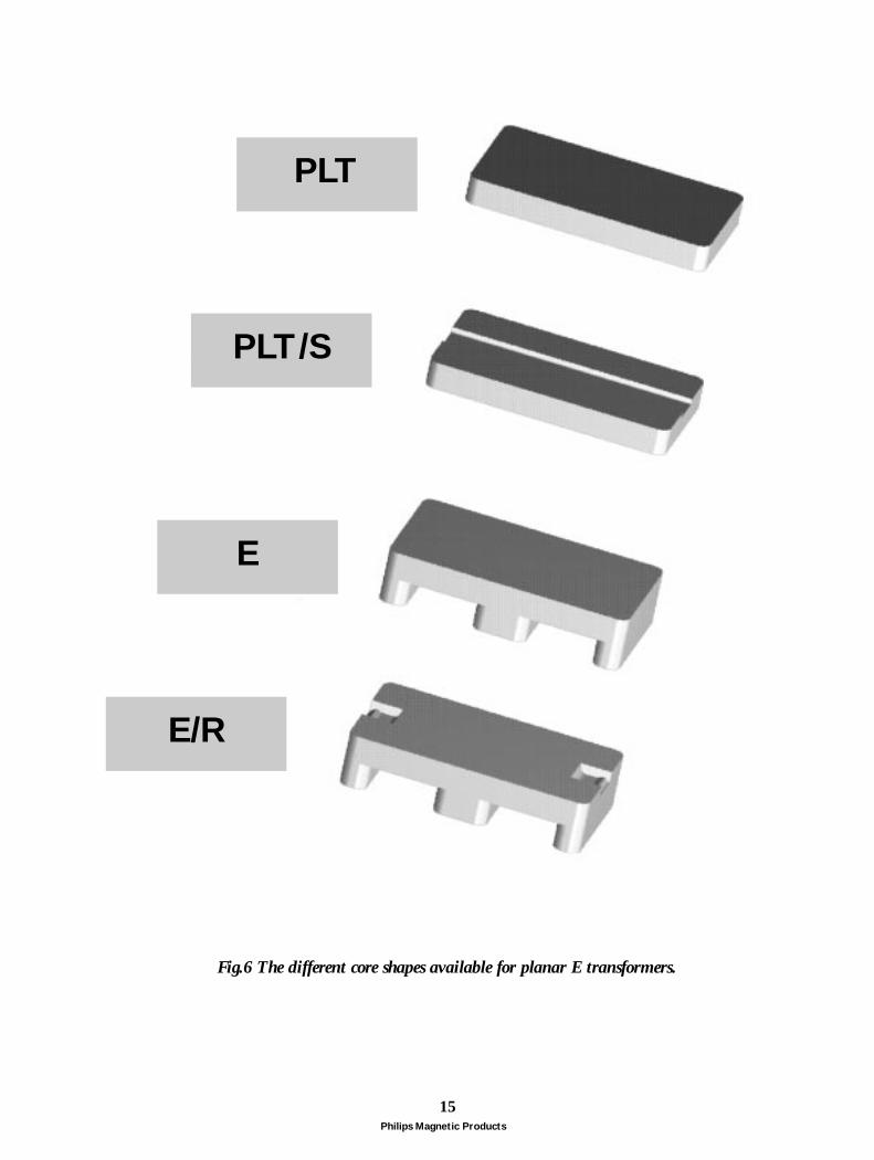
PLT
PLT/S
E/R
E
Fig.6 The different core shapes available for planar E transformers.
Philips Magnetic Products
16
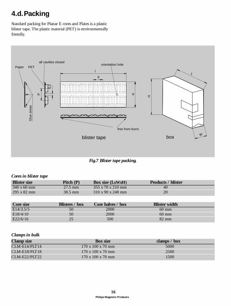
4.d.Packing
Blister size Pitch (P) Box size (LxWxH) Products / blister340 x 60 mm 27.5 mm 355 x 70 x 210 mm 40295 x 82 mm 38.5 mm 310 x 90 x 248 mm 20
Standard packing for Planar E cores and Plates is a plasticblister tape. The plastic material (PET) is environmentallyfriendly.
Core size Blisters / box Core halves / box Blister widthE14/3.5/5 50 2000 60 mmE18/4/10 50 2000 60 mmE22/6/16 25 500 82 mm
Clamp size Box size clamps / boxCLM-E14/PLT14 170 x 100 x 70 mm 5000CLM-E18/PLT18 170 x 100 x 70 mm 2500CLM-E22/PLT22 170 x 100 x 70 mm 1500
Clamps in bulk
Cores in blister tape
all cavities closed
free from burrs
Glu
e ar
eas
orientation holePETPaper
P
S
6,2
l
w
L
H
Wboxblister tape
Fig.7 Blister tape packing.

Philips Magnetic Products
17
For E14/3.5/5 and E18/4/10, a prototype version of tapeon reel packing has been developed to facilitate automaticmounting with SMD pick & place equipment. Thepacking method is in accordance with IEC-286, part 3.The plastic material (0.3 mm PET) is environmentallyfriendly. Plates have the same packing as the correspondingE cores.
Core size Pitch Tape width Reel diameter Core halves / reelE14/3.5/5 8 mm 24 mm 330 mm 2000E18/4/10 16 mm 32 mm 330 mm 900
Cores in tape on reel
24 ±
0.3
11.5
± 0
.1
1.75
± 0
.1
14.6
± 0
.2
9.9
± 0.
3
4.1
± 0.
3
2.25
4 ± 0.2
0.3
5.4 ± 0.2
1.5+0.1
4 ± 0.1
8 ± 0.1
1.5 + 0.1
E14/3.5/5
2+0.1
10.5±0.2
4 ± 0.1
32 ±
0.3
28.4
± 0
.1
14.2
± 0
.1
1.75
± 0
.1
18.7
± 0
.2
12.4
± 0
.3
5.6
± 0.
3
2.25
4.5 ± 0.2
0.3
16 ± 0.1
1.5 + 0.1
E18/4/10
Fig.8 Tape on reel packing for E14/3.5/5.
Fig.9 Tape on reel packing for E18//4/10.

Philips Magnetic Products
18
5.DesignIn order to make full use of the advantages of planartechnology, the design concept must be different from awire-wound design. A few points are highlighted below. Fora complete design procedure of planar power transformerswith examples, see the brochure “ Design of Planar Powertransformers”. For a completely worked-out example of aDC/DC converter, see the brochure "25 Watt DC/DCconverter using integrated planar magnetics".
5.a.Core choiceFlux densityThe improved heat management allows for up to twice thepower loss of a conventional design with the same magneticvolume, so optimum flux density will be higher than for aconventional design.Air gapLarge air gaps are not favourable in a planar design becauseof stray flux. The flux fringing factor depends on the ratioof winding window height to air gap length, which is lowerfor a flat core. If the window height is only a few times thegap length and the window breadth is several times thecentre post width, then even considerable flux crossingbetween core top and bottom will occur. More flux fringingand flux crossing lead to higher eddy current loss in thewinding.
a )
b )
c )
Fig.10 Different winding designs
5.b.Winding designDC resistanceOften used copper track heights are 35 and 70 µm. If thecopper cross-section is not enough for an acceptable DCresistance, then tracks can be connected in parallel for all orpart of the turns.AC resistanceAC copper losses due to skin and proximity effect are lowerfor flat copper tracks than for round wire with the samecross-sectional area. Eddy currents induced in the vicinityof a gap can be reduced by deleting a few turns where theflux density is maximum and perpendicular to the windingplane. The E / plate combination has somewhat less strayflux than the E / E combination because of the gapposition.Leakage inductanceWith vertically stacked windings, the magnetic couplingwill be very strong and coupling factors close to 100 % canbe achieved (Fig.10a).Parasitic capacitanceThe former will lead to higher inter-winding capacitance.This capacitance can be reduced by projecting the tracks ofa winding in between the tracks of the adjacent winding(Fig.10b). Furthermore, the repeatability of the capacitance allows foreither compensating it in the rest of the circuit or using itin a resonant design. In the latter case, a high capacitancecould be chosen on purpose by placing the tracks ofadjacent windings face to face (Fig.10c).

Philips Magnetic Products
19
6.Manufacturing6.a.AssemblyStand-alone : not essentially different from conventional.For glue and curing proposals, see the application note"Gluing of ferrite cores". The high permeability ferrite 3E6should not be glued between the mating faces, because theparasitic gap reduces effective permeability. Glue can beapplied on the sides of the outer legs (Fig. 11).Clamping is done by first pressing the clamp into the snap-fit and then aligning the plate in transversal direction.Integrated : assembly is combined with mounting.
6.b.MountingStand-alone : through-hole or SMD, not essentiallydifferent from conventional.The flat core surface is well suited for pick & place systems.Integrated : can best be done in 2 steps.
1). Glue one core half to the PCB. The same glue can beused as for attaching SMD components and this step islogically combined with SMD mounting on the same PCBside.
2). Glue or clamp the second core half to the first one. Thesame remarks apply here as for stand-alone assembly.
6.c.SolderingOnly applicable for stand-alone transformers.In case of reflow soldering, hot air convection is preferredover IR radiation heating, because it equalises thetemperature differences. With standard IR radiationheating, the good thermal conduction of the planarcomponent can lead to a too low solder paste temperatureor there can be a too high PCB temperature if radiationpower is increased. In case of IR reflow soldering, it isadvised to use modified solder paste and/or PCB material.
d o t o f g l u e d o t o f g l u e
Fig.11 Gluing of planar E cores

Philips Magnetic Products
20
All planar core type numbers correspond to a core half.Therefore two core halves have to be ordered in the rightcombination. There are 4 core half types combined to 3types of core sets :E + E, E + PLT and E/R + PLT/S. The last one iscompleted with a clamp (CLM).
25 Watt DC/DC converter using integrated planar magnetics 9398 236 26011Gluing of Ferrite Cores 9398 083 20011Design of Planar Power Transformers 9398 083 39011SAMPLEBOX7 : Small planar E cores in 3F3 4322 020 85131SAMPLEBOX8 : Medium planar E cores in 3C85 & 3F3 4335 000 40971
7.Literature & sample boxes
8.Type number system
E14/3.5/5/R-3F3-A100-P
core type
clamp recess(if recessed: /R)
material
PLT14/5/1.5/S-3F3
core type
core size(always 3dim.) clamp slot
(if slotted: /S)
material
E core
core size(ungapped: 3dim.)(gapped: 2dim.)
mating partP: combine wit plateE: combine with E core
gap typeA: asymmetrical gapE: symmetrical gap
AL value (nH)
Plate
CLM-E18/PLT18
accessory type
corresponding E core(only main dim.)
Clamp
corresponding plate(only main dim.)

Magnetic Products NAFTA Sales Offices
Alabama Over and Over, Inc., Charlotte, NC (708) 583-9100Alaska Eclipse Marketing Group, Redmond, WA (206) 885-6991Arizona Harper and Two, Tempe, AZ (602) 804-1290Arkansas Philips Components, Willoughby, OH (440) 269-8585California - Northern Criterion Sales, Santa Clara, CA (408) 988-6300California - Southern Harper and Two, Signal Hill, CA (801) 264-8050Colorado Philips Components, Willoughby, OH (440) 269-8585Connecticut Philips Components, Woburn, MA (617) 932-4748Deleware Philips Components, Woburn, MA (617) 932-4748Florida Over and Over, Charlotte, NC (704) 583-9100Georgia Over and Over, Charlotte, NC (704) 583-9100Hawaii Harper and Two, Signal Hill, CA (310) 424-3030Idaho - Northern Eclipse Marketing Group, Redmond, WA (206) 885-6991Idaho - Southern Electrodyne, Inc., Salt Lake City, UT (801) 264-8050Illinois - Northern Philips Components, Willoughby, OH (440) 269-8585Illinois - Quad Cities Lorenz Sales, Cedar Rapids, IA (319) 377-4666Illinois - Southern Lorenz Sales, St. Louis, MO (314) 997-4558Indiana - Northern Corrao Marsh, Fort Wayne, IN (219) 482-2725Indiana - Central and Southern Corrao Marsh, Greenfield, IN (317) 462-4446Iowa - All except Quad Cities Lorenz Sales, Cedar Rapids, IA (319) 377-4666Kansas - Northeast Lorenz Sales, Overland Park, KS (913) 469-1312Kansas - All except Northeast Lorenz Sales, Wichita, KS (316) 721-0500Kentucky Corrao Marsh, Greenfield, IN (317) 462-4446Louisiana Philips Components, Willoughby, OH (440) 269-8585Maine Philips Components, Woburn, MA (617) 932-4748Maryland Philips Components, Willoughby, OH (440) 269-8585Massachusetts Philips Components, Woburn, MA (617) 932-4748Michigan Philips Components, Willoughby, OH (440) 269-8585Minnesota Electronic Component Sales, Minneapolis, MN (612) 946-9510Mississippi Over and Over, Charlotte, NC (704) 583-9100Missouri - Eastern Lorenz Sales, St. Louis, MO (314) 997-4558Missouri - Western Lorenz Sales, Overland Park, KS (913) 469-1312Montana Electrodyne, Inc., Salt Lake City, UT (801) 264-8050Nebraska Lorenz Sales, Cedar Rapids, IA (319) 377-4666Nevada - Central and Northern Criterion Sales, Santa Clara, CA (408) 988-6300Nevada - Sourthern Harper and Two, Tempe, AZ (602) 804-1290New Hampshire Philips Components, Woburn, MA (617) 932-4748New Jersey Philips Components, Woburn, MA (617) 932-4748New Mexico Harper and Two, Tempe, AZ (602) 804-1290New York - Western Philips Components, Willoughby, OH (440) 269-8585New York - All other Philips Components, Woburn, MA (617) 932-4748North Carlolina Over and Over, Charlotte, NC (704) 583-9100North Dakota Electronic Component Sales, Minneapolis, MN (612) 946-9510Ohio Philips Components, Willoughby, OH (440) 269-8585Oklahoma Philips Components, Willoughby, OH (440) 269-8585Oregon Eclipse Marketing Group, Beaverton, OR (503) 642-1661Pennsylvania - Western Philips Components, Willoughby, OH (440) 269-8585Pennsylvania - Eastern Philips Components, Woburn, MA (617) 932-4748Rhode Island Philips Components, Woburn, MA (617) 932-4748South Carolina Over and Over, Charlotte, NC (704) 583-9100South Dakota Electronic Component Sales, Minneapolis, MN (612) 946-9510Tennesse Over and Over, Charlotte, NC (704) 583-9100Texas Philips Components, Willoughby, OH (440) 269-8585Utah Electrodyne, Inc., Salt Lake City, UT (801) 264-8050Vermont Philips Components, Woburn, MA (617) 932-4748Virginia Philips Components, Willoughby, OH (440) 269-8585Washington Eclipse Marketing Group, Redmond, WA (206) 885-6991Washington DC Philips Components, Willoughby, OH (440) 269-8585West Virginia Philips Components, Willoughby, OH (440) 269-8585Wisconsin Philips Components, Willoughby, OH (440) 269-8585Wyoming Electrodyne, Inc., Salt Lake City, UT (801) 264-8050Canada Philips Components, Scarborough, ON (416) 292-5161Mexico Philips Components, El Paso, TX (915) 772-4020Puerto Rico Max Anderson Co., Caperra Heights, PR (809) 783-6544Virgin Islands Max Anderson Co., Caperra Heights, PR (809) 783-6544

PhilipsComponents
Philips Components – a worldwide companyAustralia: Philips Components Pty Ltd., NORTH RYDE,
Tel. +61 2 9805 4455, Fax. +61 2 9805 4466
Austria: Österreichische Philips Industrie GmbH, WIEN,Tel. +43 1 60 101 12 41, Fax. +43 1 60 101 12 11
Belarus: Philips Office Belarus, MINSK,Tel. +375 172 200 924/733, Fax. +375 172 200 773
Benelux: Philips Nederland B.V., EINDHOVEN, NL,Tel. +31 40 2783 749, Fax. +31 40 2788 399
Brazil: Philips Components, SÃO PAULO,Tel. +55 11 821 2333, Fax. +55 11 829 1849
Canada: Philips Electronics Ltd., SCARBOROUGH,Tel. +1 416 292 5161, Fax. +1 416 754 6248
China: Philips Company, SHANGHAI,Tel. +86 21 6354 1088, Fax. +86 21 6354 1060
Denmark: Philips Components A/S, COPENHAGEN S,Tel. +45 32 883 333, Fax. +45 31 571 949
Finland: Philips Components, ESPOO,Tel. +358 9 615 800, Fax. +358 9 615 80510
France: Philips Composants, SURESNES,Tel. +33 1 4099 6161, Fax. +33 1 4099 6493
Germany: Philips Components GmbH, HAMBURG, Tel. +49 40 2489-0, Fax. +49 40 2489 1400
Greece: Philips Hellas S.A., TAVROS,Tel. +30 1 4894 339/+30 1 4894 239, Fax. +30 1 4814 240
Hong Kong: Philips Hong Kong, KOWLOON,Tel. +852 2784 3000, Fax. +852 2784 3003
India: Philips India Ltd., MUMBAI,Tel. +91 22 4930 311, Fax. +91 22 4930 966/4950 304
Indonesia: P.T. Philips Development Corp., JAKARTA,Tel. +62 21 794 0040, Fax. +62 21 794 0080
Ireland: Philips Electronics (Ireland) Ltd., DUBLIN,Tel. +353 1 7640 203, Fax. +353 1 7640 210
Israel: Rapac Electronics Ltd., TEL AVIV,Tel. +972 3 6450 444, Fax. +972 3 6491 007
Italy: Philips Components S.r.l., MILANO,Tel. +39 2 6752 2531, Fax. +39 2 6752 2557
Japan: Philips Japan Ltd., TOKYO,Tel. +81 3 3740 5135, Fax. +81 3 3740 5035
Korea (Republic of): Philips Electronics (Korea) Ltd., SEOUL,Tel. +82 2 709 1472, Fax. +82 2 709 1480
Malaysia: Philips Malaysia SDN Berhad,Components Division, PULAU PINANG, Tel. +60 3 750 5213, Fax. +60 3 757 4880
Mexico: Philips Components, EL PASO, U.S.A.,Tel. +52 915 772 4020, Fax. +52 915 772 4332
New Zealand: Philips New Zealand Ltd., AUCKLAND,Tel. +64 9 815 4000, Fax. +64 9 849 7811
Norway: Norsk A/S Philips, OSLO,Tel. +47 22 74 8000, Fax. +47 22 74 8341
Pakistan: Philips Electrical Industries of Pakistan Ltd., KARACHI,Tel. +92 21 587 4641-49, Fax. +92 21 577 035/+92 21 587 4546
Philippines: Philips Semiconductors Philippines Inc., METRO MANILA, Tel. +63 2 816 6345, Fax. +63 2 817 3474
Poland: Philips Poland Sp. z.o.o., WARSZAWA,Tel. +48 22 612 2594, Fax. +48 22 612 2327
Portugal: Philips Portuguesa S.A.,Philips Components: LINDA-A-VELHA, Tel. +351 1 416 3160/416 3333, Fax. +351 1 416 3174/416 3366
Russia: Philips Russia, MOSCOW,Tel. +7 95 755 6918, Fax. +7 95 755 6919
Singapore: Philips Singapore Pte Ltd., SINGAPORE,Tel. +65 350 2000, Fax. +65 355 1758
South Africa: S.A. Philips Pty Ltd., JOHANNESBURG,Tel. +27 11 470 5911, Fax. +27 11 470 5494
Spain: Philips Components, BARCELONA,Tel. +34 93 301 63 12, Fax. +34 93 301 42 43
Sweden: Philips Components AB, STOCKHOLM,Tel. +46 8 5985 2000, Fax. +46 8 5985 2745
Switzerland: Philips Components AG, ZÜRICH,Tel. +41 1 488 22 11, Fax. +41 1 481 7730
Taiwan: Philips Taiwan Ltd., TAIPEI,Tel. +886 2 2134 2900, Fax. +886 2 2134 2929
Thailand: Philips Electronics (Thailand) Ltd., BANGKOK, Tel. +66 2 745 4090, Fax. +66 2 398 0793
Turkey: Türk Philips Ticaret A.S., GÜLTEPE/ISTANBUL,Tel. +90 212 279 2770, Fax. +90 212 282 6707
United Kingdom: Philips Components Ltd., DORKING,Tel. +44 1306 512 000, Fax. +44 1306 512 345
United States:
• Display Components, ANN ARBOR, MI,Tel. +1 734 996 9400, Fax. +1 734 761 2776
• Magnetic Products, SAUGERTIES, NY,Tel. +1 914 246 2811, Fax. +1 914 246 0487
• Passive Components, SAN JOSE, CA,Tel. +1 408 570 5600, Fax. +1 408 570 5700
Yugoslavia (Federal Republic of): Philips Components, BELGRADE,Tel. +381 11 625 344/373, Fax. +381 11 635 777
Internet:
• Display Components: www.dc.comp.philips.com• Passive Components: www.passives.comp.philips.com
For all other countries apply to: Philips Components, Building BF-1, P.O. Box 218, 5600 MD EINDHOVEN,The Netherlands, Fax. +31-40-27 23 903.
COD19 Ó Philips Electronics N.V. 1998
All rights are reserved. Reproduction in whole or in part is prohibited without theprior written consent of the copyright owner.The information presented in this document does not form part of any quotation orcontract, is believed to be accurate and reliable and may be changed without notice.No liability will be accepted by the publisher for any consequence of its use. Publicationthereof does not convey nor imply any license under patent- or other industrial orintellectual property rights.
Printed in The Netherlands
Document order number: 9398 083 40011 Date of release: 07/97