planar satcom antenna systems in ka-band otto · planar satcom antenna systems in ka-band...
TRANSCRIPT
PLANAR SATCOM ANTENNA SYSTEMS IN KA-BAND
ESA/ESTEC, NOORDWIJK, THE NETHERLANDS 3-5 OCTOBER 2012
S. Otto, I. Nistal, S. Holzwarth, O. Litschke, R. Baggen
IMST, Carl-Friedrich-Gauss-Str. 2-4, 47475 Kamp-Lintfort, Germany. Email: [email protected], [email protected], [email protected], [email protected], [email protected]
ABSTRACT
Nomadic and mobile satellite communication (satcom) services for broadband applications are becoming more and more popular every day. Ka-band terminals are favored for the next generation of satcom terminals. Key results of two Ka-band projects (SANTANA & KASANOVA) are summarized and typical features of such satcom systems are addressed. 1. INTRODUCTION
Nomadic and mobile satcom services for broadband applications are becoming increasingly attractive nowadays; users demand multimedia access at any time at any place. In order to accommodate for the large bandwidths required and the growing number of users, higher frequency bands such as Ka-band are opened for the next generation of satcom terminals. Such terminals have to operate in nomadic or mobile user scenarios and require in most cases smart and agile antenna solutions that either can be easily deployed, or are capable of tracking the satellite on-the-move. Through the years, satcom antenna frontends have become a key area at IMST. In this paper, two satcom projects (from the past and on-going) in Ka-Band are presented. First, some key results of a project from the past, SANTANA, will be shown. Secondly, an on-going joint project of Astrium and IMST, KASANOVA, is introduced and preliminary results are presented. 2. SANTANA
SANTANA (I-II-III) focused on Digital Beam Forming (DBF) [1][2][3] and was supported and funded by the German Ministry of Education and Research (BMBF/DLR), in cooperation with the Technical University of Hamburg, DLR and Astrium. The application are airborne Ka-band satellite terminals for broadband multimedia services (internet in the sky). The DBF-terminal itself has been divided into a separate Tx (30 GHz) and Rx (20 GHz) antenna array. The frequency bands are based on upcoming satellite multimedia applications and the polarization is circular, so only the beam has to be steered; the polarization
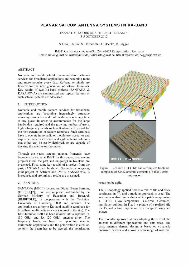
Figure 1. Realized LTCC tile and a complete frontend composed of 32x32 antenna elements (16 tiles), artist
impression needs not be agile. The RF-topology applied here is a mix of tile and brick configuration [4], and a modular approach is used. The antenna is realized in modules of 8x8 patch arrays using a LTCC (Low-Temperature Co-fired Ceramics) multilayer buildup. In Fig. 1 a picture of a realized tile for Tx and a first impression of a complete array are shown.
The modular approach allows adapting the size of the antenna to different applications and data rates. The basic antenna element design is based on circularly polarized patches and allows a scan range of maximal

60° from boresight (typical restrictions of a planar layout of the array). The circular polarization of the patch elements is achieved by using two decoupled feeds and one 90° hybrid ring per element. In addition, the antenna elements are sequentially rotated to improve the polarization behavior of the array. One multilayer LTCC Tx-module consists of 17 layers of FERRO A6 and contains the following key components: o 64 antenna elements, o hybrid ring feeds, o internal calibration network, o cooling channels (liquid cooling).
All are integrated in one complex LTCC tile (Fig. 2) with the antenna elements located on one side, and on the other side, the 64 PA’s (Power Amplifier), corresponding peripheries and connectors for LO (Local Oscillator), DC, IF and liquid cooling (Fig. 3). One tile can be calibrated automatically using an internal calibration receiver. The components used are all off-the-shelf in order to reduce development costs.
Figure 2. Layout of the 17 layer LTCC buildup (backside view with all PA & connectors visible)
The antenna can be pointed in any fixed azimuth-plane within an elevation from boresight of 60° without any scan blindness problems. The side lobe levels are maintained at levels of approximately 13 dB (no amplitude taper applied) and a very good suppression (> 20 dB) of the cross-polar component can also be observed. The good polarization performance is the result of several factors: (i) the feeding of the antenna elements using the hybrid ring coupler allows for a very good axial ratio of each single element, (ii) in addition, the hybrid ring feeding also attenuates the cross-polar components resulting from coupling effects, (iii) finally,
Figure 3. Realization of the 8x8 LTCC antenna tile
the sequential rotation of the antenna elements improves the axial ratio at the array level. The complete buildup consists not only of the antenna frontend realized in LTCC and an up-converting RF-circuitry, but also of

the complete digital hardware necessary for the controlling of the antenna signals at digital level. The DBF-architecture considered for SANTANA requires a high degree of integration with respect to the large number of components and a high speed digital processing unit. The real-time processing of thousands of antenna element signals is however not feasible. Therefore, alternative topologies are under investigation at IMST that are combinations of DBF-technology and special IF-feeding architectures. The concept behind such topologies is to reduce the number of interconnections between the RF-part and digital logic, thus reducing the number of antenna element signals to be processed (reduction of the computational load). 3. KASANOVA
Within the frame of the KASANOVA project, funded by the German “Bundesministerium für Wirtschaft und Technologie” BMWi, under the research contract 50YB1024, Astrium is developing the infrastructure and corresponding satcom services for disaster relief management. For these scenarios, IMST is developing a nomadic Ka-Band planar antenna terminal (Tx: 29.5-30 GHz & Rx: 19.7-20.2 GHz) to be used for disaster relief vehicles looking towards the future exploitation of high data rates in the Ka-band. The KASANOVA antenna aims at a hybrid solution, i.e. a combined mechanical/electrical beam steering. The mechanical positioning shall be achieved with an accuracy of approximately ±1° in azimuth and elevation, hence providing a coarse beam pointing towards the satellite. The fine positioning of the beam between -1° and 1° from boresight will be achieved electronically by means of four individual sub-arrays via true time delays. The Tx antenna aperture is composed of circular horn antenna elements that are uniformly fed by two waveguide distribution networks, one for horizontal and the other for vertical polarization, respectively. Arbitrary polarizations including circular polarization can be achieved by properly combining these two. The Rx aperture is formed by a separate antenna, with the Rx horn element and the Rx waveguide networks being a scaled version (factor 1.5) of the Tx geometry. Here, the concept and first measurement results of part of the antenna aperture under development are presented. Fig. 4 and Fig. 5 show the Rx and Tx architecture of the hybrid beam steering system, respectively. A mechanical positioning unit provided by the German company ten Haaft is employed having a pointing accuracy of ±1°. The antenna aperture is divided into three sub-arrays in the Rx case and four sub-arrays in the Tx case. Each sub-array is connected to a separate Low Noise Block (LNB) or Block Up
Converter (BUC) with a true time delay in the L-band. A time delay range of 15 ps for Tx and 25 ps for Rx can be controlled in discrete steps with the antenna control unit board shown in Fig. 6, where the time delays are composed of switched transmission lines with different lengths.
Figure 4. Rx-architecture of the hybrid
mechanical/electrical beam steering antenna
Figure 5. Tx-architecture of the hybrid
mechanical/electrical beam steering antenna
Figure 6. Antenna control unit board with true time
delays in the L-band for Rx and Tx
Fig. 7 shows the fabricated prototype of an 8x8 element Tx antenna, which is used to validate the simulations performed with the FDTD-based (Finite-Difference
Time-Domain) field solver EMPIRE XCcel. Furthermore, the prototype makes it possible to investigate the influence of manufacturing tolerances on the antenna performance including the antenna efficiency. The element spacing is approximately one free space wavelength λ. This is necessary in order to incorporate two waveguide networks with a reasonable waveguide/channel spacing of at least 1mm. This ensures a proper mechanical support and paves the way for plastic injected molding technologies. The two networks are necessary in order to generate circular polarization. The grating lobes induced by the element spacing can be minimized by adjusting the horn taper of the radiator element, so to superimpose the grating lobe in the array factor with a null at the element factor.
Figure 7. Proof of concept: 8x8 elements aperture (1) and two stacked waveguide networks for horizontal (2)
and vertical polarization (3) for achieving arbitrary polarization control
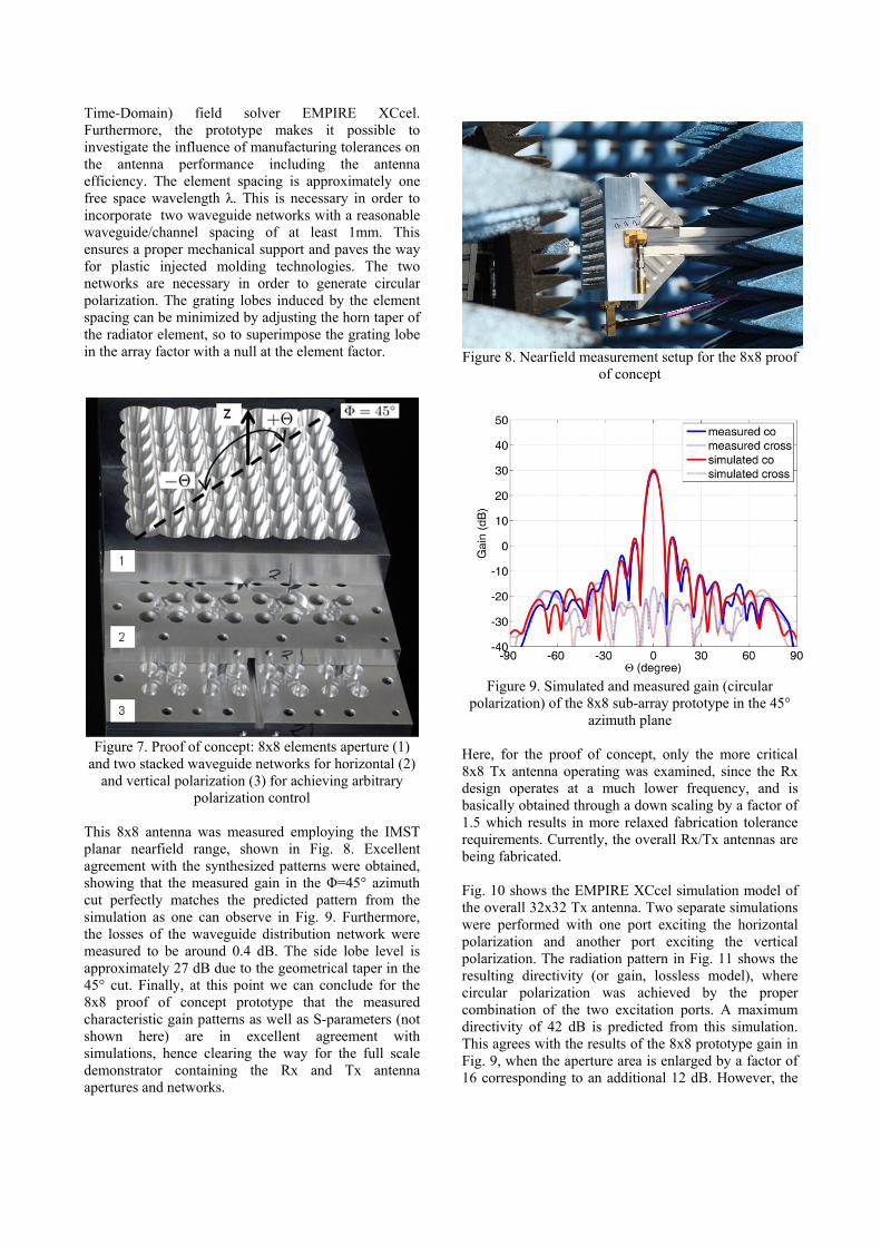
This 8x8 antenna was measured employing the IMST planar nearfield range, shown in Fig. 8. Excellent agreement with the synthesized patterns were obtained, showing that the measured gain in the Φ=45° azimuth cut perfectly matches the predicted pattern from the simulation as one can observe in Fig. 9. Furthermore, the losses of the waveguide distribution network were measured to be around 0.4 dB. The side lobe level is approximately 27 dB due to the geometrical taper in the 45° cut. Finally, at this point we can conclude for the 8x8 proof of concept prototype that the measured characteristic gain patterns as well as S-parameters (not shown here) are in excellent agreement with simulations, hence clearing the way for the full scale demonstrator containing the Rx and Tx antenna apertures and networks.
Figure 8. Nearfield measurement setup for the 8x8 proof
of concept
Figure 9. Simulated and measured gain (circular
polarization) of the 8x8 sub-array prototype in the 45° azimuth plane
Here, for the proof of concept, only the more critical 8x8 Tx antenna operating was examined, since the Rx design operates at a much lower frequency, and is basically obtained through a down scaling by a factor of 1.5 which results in more relaxed fabrication tolerance requirements. Currently, the overall Rx/Tx antennas are being fabricated. Fig. 10 shows the EMPIRE XCcel simulation model of the overall 32x32 Tx antenna. Two separate simulations were performed with one port exciting the horizontal polarization and another port exciting the vertical polarization. The radiation pattern in Fig. 11 shows the resulting directivity (or gain, lossless model), where circular polarization was achieved by the proper combination of the two excitation ports. A maximum directivity of 42 dB is predicted from this simulation. This agrees with the results of the 8x8 prototype gain in Fig. 9, when the aperture area is enlarged by a factor of 16 corresponding to an additional 12 dB. However, the

network losses will increase and a final gain of approximately 41 dB in the measurement is expected.
Figure 10. Simulation model, including the two
waveguide distribution networks of the 32x32 elements Tx antenna aperture
Figure 11. Simulated gain of the 32x32 elements Tx
antenna aperture 4. CONCLUSIONS
In this paper two Ka-Band satcom projects from the past and present have been presented. The project from the past, SANTANA focused on highly complex DBF-architectures. The overall realization has been presented and details of the RF-part have been discussed. It has been technologically one of the most challenging antenna projects conducted at IMST. The other project, KASANOVA, that is still on-going, aims at planar hybrid solution with a medium complexity for nomadic satcom applications. This antenna aims at the combination of mechanically and electronically steering using true time delays. Innovative waveguide technology is applied here to arrive at a cost-effective
realization, hopefully resulting in a successful market introduction of such terminals. 5. ACKNOWLEDGEMENTS
The authors wish to thank the German Ministry of Education and Research (BMBF/BMWi/DLR) for funding the projects SANTANA (I-II-III) and KASANOVA under research contracts 50YB0101, 50YB0311, 50YB0710 and 50YB1024, respectively. 6. REFERENCES
[1] Dreher A. et al., Ka-band DBF terminal concepts for broadband satellite communications, Conference Proceedings 25th ESA Antenna Workshop on Satellite Antenna Technology, Noordwijk, The Netherlands, pp. 95-102, September 2002.
[2] Geise A. et al., Smart antenna terminals for broadband mobile satellite communications at Ka-Band, Conference Proceedings INICA 2007, Munich, 2007.
[3] Holzwarth S., O. Litschke, W. Simon, K. Kuhlmann, A. Jacob, Far Field Pattern Analysis and Measurement of a digital Beam Forming 8x8 Antenna Array Transmitting from 29.5 to 30 GHz, Conference Proceedings EUCAP 2007, Edinburgh, November 2007.
[4] Baggen L., B. Sanadgol, M. Boettcher, S. Holzwarth, O. Litschke, Designing Integrated Frontends for Satcom Applications, Conference proceedings CAS International Semiconductor Conference 2012, Sinaia, Romania, October 2012.