planning advice note: pan 62 radio … complements the national planning policy guideline on radio...
TRANSCRIPT

1
Planning Advice Note: PAN 62 Radio Telecommunications
Introduction
1. The Scottish Executive is committed to securing world class telecommunications
services for Scotland while safeguarding our natural and built environment. This Advice
Note will be of interest to planning authorities, the industry, its operators and agents,
and the general public. It complements the National Planning Policy Guideline on Radio
Telecommunications (NPPG19), and highlights examples of good practice from across
Scotland and beyond.
2. There has been a degree of public concern about siting and design of mobile base
stations, particularly masts. To help operators and planning authorities allay these
concerns, this PAN gives advice on the process of site selection and design and
illustrates how the equipment can be sensitively installed. It also explains why additional
base stations are needed to serve the growth in customer demand and in response to
changing technical requirements, including the third generation of mobile phones.
3. As a consequence of the changes made in The Town and County Planning (General
Permitted Development) (Scotland) Amendment (No. 2) Order 2001 (SSI 2001 No. 266)
(the GPDO), the planning system is dealing with an increased number of applications for
the erection and alteration of radio telecommunications equipment.
4. This PAN is relevant to the full range of radio telecommunications equipment. This
includes mobile, Fixed Radio Access (FRA), microwave link, television and radio
broadcasting, paging, police, taxi and private telecommunication systems. Continued
expansion of these systems is expected for the foreseeable future. It provides
information on:
how radio telecommunication systems operate;
radio telecommunications equipment;
minimising environmental impact through good siting and design;
local plans and supplementary guidance; and
development control.

2
Radio Telecommunications Systems
5. This section provides an overview of the main radio telecommunication services
currently in use or being developed, including a description of the most commonly used
equipment. Each system has different equipment and siting requirements and there are
continual technical innovations so it is important for planning authorities and operators
to maintain a constructive dialogue.
6. Operators of radio telecommunication systems require licences under the
Telecommunications Act 1984 and the Wireless Telegraphy Act (1949 and 1998) to run
their systems. The licences are issued by the Secretary of State for Trade and Industry,
but enforced and where necessary amended by the Director General of
Telecommunications ( see Glossary). Some licences give operators special rights and
obligations, known as "Code Powers", to facilitate the installation of their systems as set
out in the Telecommunication Code. Licensees to whom the telecommunications code is
applied are known as code system operators.
7. Under the terms of their licences operators are required, 28 days prior to the first
occasion they intend to install any telecommunications apparatus, to give the planning
authority written details of their expected rollout plans in that authority's area. There are
no further requirements under the licences to notify planning authorities, although there
are requirements for permitted development (see GPDO). The licences require operators
to ensure the visual amenity of properties is protected as far as practicable and that
before erecting a mast or pole the possibility is investigated of using an existing mast or
pole. For further information on the licences and the telecommunications code see Annex
D.
MOBILE RADIO TELECOMMUNICATION SYSTEMS
8. There has been remarkable growth in mobile services, which use radio signals
between radio base stations and portable radio handsets, with over 40 million
subscribers in the UK in 2001. Handsets are used for voice communication but also
increasingly for transfer of business, education, shopping and entertainment information.
There is a growing convergence between the broadcasting, telecommunications and
information technology sectors. It is predicted that the number of users and volume of
calls will continue to grow.
9. Mobile telecommunication systems work by using and re-using the same radio
frequencies and allocating them to geographical cells. Mobile operators divide the
country into thousands of individual cells and at the centre of each is a base station.
Base stations are connected to one another by central switching centres, which track
calls and transfer them as the caller moves from one cell to the next. The area covered
by each cell is governed by the anticipated capacity (i.e. volume of calls), the height of
the antenna above the ground, the local terrain, the power output and the radio
frequency - in general the higher the frequency, the shorter the distance the signal
travels. The largest cells are in sparsely populated rural areas and the smallest in town
3
and city centres. Splitting a cell into smaller cells can increase capacity. There is a great
variety in the way cells are configured and split. Most base stations are in built-up areas
and elsewhere within a mile or two of the main transport corridors.
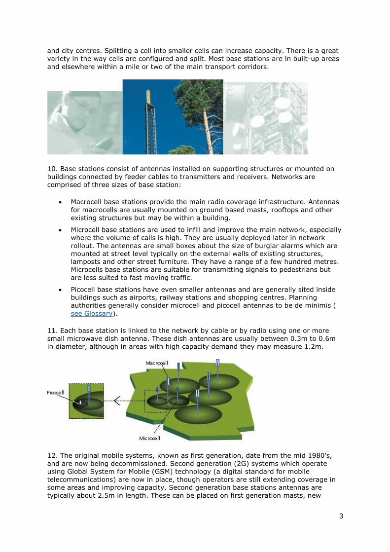
10. Base stations consist of antennas installed on supporting structures or mounted on
buildings connected by feeder cables to transmitters and receivers. Networks are
comprised of three sizes of base station:
Macrocell base stations provide the main radio coverage infrastructure. Antennas
for macrocells are usually mounted on ground based masts, rooftops and other
existing structures but may be within a building.
Microcell base stations are used to infill and improve the main network, especially
where the volume of calls is high. They are usually deployed later in network
rollout. The antennas are small boxes about the size of burglar alarms which are
mounted at street level typically on the external walls of existing structures,
lamposts and other street furniture. They have a range of a few hundred metres.
Microcells base stations are suitable for transmitting signals to pedestrians but
are less suited to fast moving traffic.
Picocell base stations have even smaller antennas and are generally sited inside
buildings such as airports, railway stations and shopping centres. Planning
authorities generally consider microcell and picocell antennas to be de minimis (
see Glossary).
11. Each base station is linked to the network by cable or by radio using one or more
small microwave dish antenna. These dish antennas are usually between 0.3m to 0.6m
in diameter, although in areas with high capacity demand they may measure 1.2m.
12. The original mobile systems, known as first generation, date from the mid 1980's,
and are now being decommissioned. Second generation (2G) systems which operate
using Global System for Mobile (GSM) technology (a digital standard for mobile
telecommunications) are now in place, though operators are still extending coverage in
some areas and improving capacity. Second generation base stations antennas are
typically about 2.5m in length. These can be placed on first generation masts, new

4
lattice or monopole masts or other existing structures. Second generation ground based
masts are generally 12.5m to 22.5m in height. Short 'stub' masts on rooftops, lattice or
monopole, are typically 4m to 6m high. Standard 2G base stations have between 2 and
6 antennas per mobile operator. Antennas can be directional to cover a segment of the
cell, or omni-directional sending the signals out in all directions ( see Glossary). Some
operators are upgrading their networks to use a common standard known as General
Packet Radio Service (GPRS), sometimes referred to as 2.5G.
Second generation lattice mast, Second generation monopole mast and Second
generation stub tower on rooftop.
13. In May 2000 the Government awarded five licences to four existing 2G operators and
a new operator. The licences will be valid until the end of 2021 and require each licensee
to develop a third generation (3G) network covering at least 80% of the UK population
by the end of 2007. Third generation systems will operate using Universal Mobile
Telecommunication Systems (UMTS) technology. It enables data transfer rates up to 200
times faster than current mobile phones and allows access to the internet on the move.
14. Third generation mobile services require more base stations than 2G because 3G
radio signals do not travel as far and the resultant smaller cells leave gaps in the radio
coverage between existing sites designed for 2G radio coverage. More are also required
because the size of a 3G cell expands and contracts according to the level of subscriber
use. This is known as 'cell breathing'.

5
Second and third generation equipment on a rooftop site. The 3G equipment is
highlighted.
15. For the earliest stages of network rollout, third generation macrocell base stations
will typically be about 3 - 5 km apart in rural and suburban areas and about 500 - 1000
metres apart in dense urban areas. Because of their smaller range 3G antennas can be
sited lower than 2G antennas. The five licence holders are expected to begin 3G
commercial services in 2002, though 3G networks are being constructed now. The new
operator will have to establish a new network and is expected to primarily use existing
buildings or other structures, including some masts used by other operators.
16. Standard 3G equipment looks similar to 2G. In most situations separate new 3G
antennas will be required. However, in some circumstances where masts are being
shared, existing second generation operators may place the third generation antenna
inside the second generation antenna casing or share a slightly wider casing.
17. A new generation of mobile technology seems to come forward approximately every
10 years. Some telecommunication companies are already thinking about fourth
generation systems.
TETRA AND PAGER SYSTEMS
18. Another mobile telecommunication system currently in use is Terrestrial Trunked
Radio (TETRA), which is a standard for digital trunked radio. One TETRA network being
developed is the Airwave service, formally known as the Public Safety Radio
Communications Project (PSRCP) which will provide greatly improved digital
communications for the emergency and other public safety services. The Airwave
national network of base stations will achieve the near 100 per cent radio coverage on all
tarmac roads, which is essential for emergency service use. Rollout in Scotland is
expected between 2004 and 2005. The system will use a relatively low radio frequency
(400 MHz) and therefore the range from each site will be larger than other mobile
systems.
19. The other TETRA network is being developed to provide a digital mobile
telecommunications service mainly to business users. There are also a number of mobile
pager systems in operation.
20. TETRA and pager systems use a great variety of antennas, which can range from 1.5
- 6 metres in length. The antennas can be sited on existing or new masts. New masts
are generally thinner than masts used by mobile operators, although new masts for the
PSRCP may need to be taller than normal to provide adequate coverage.
6
PRIVATE BUSINESS RADIO
21. Private Business Radio (PBR) systems provide voice only communication over ranges
up to 80km, dependent on the equipment used and terrain. PBR systems can be on-site
for instance in supermarkets or offices, wide area as used by airports and taxi firms, or
national and regional networks as used by road breakdown services or utility companies.
They utilise slim antennas which due to their small size are often considered to be de
minimis.
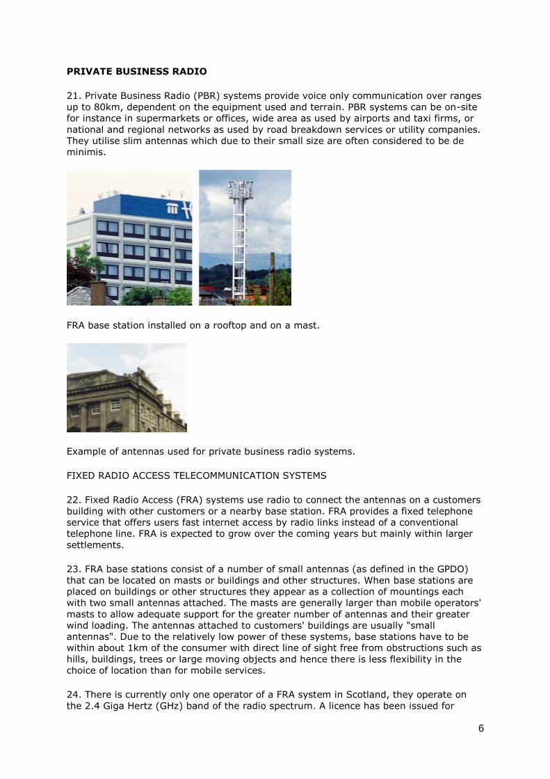
FRA base station installed on a rooftop and on a mast.
Example of antennas used for private business radio systems.
FIXED RADIO ACCESS TELECOMMUNICATION SYSTEMS
22. Fixed Radio Access (FRA) systems use radio to connect the antennas on a customers
building with other customers or a nearby base station. FRA provides a fixed telephone
service that offers users fast internet access by radio links instead of a conventional
telephone line. FRA is expected to grow over the coming years but mainly within larger
settlements.
23. FRA base stations consist of a number of small antennas (as defined in the GPDO)
that can be located on masts or buildings and other structures. When base stations are
placed on buildings or other structures they appear as a collection of mountings each
with two small antennas attached. The masts are generally larger than mobile operators'
masts to allow adequate support for the greater number of antennas and their greater
wind loading. The antennas attached to customers' buildings are usually "small
antennas". Due to the relatively low power of these systems, base stations have to be
within about 1km of the consumer with direct line of sight free from obstructions such as
hills, buildings, trees or large moving objects and hence there is less flexibility in the
choice of location than for mobile services.
24. There is currently only one operator of a FRA system in Scotland, they operate on
the 2.4 Giga Hertz (GHz) band of the radio spectrum. A licence has been issued for

7
another operator of a FRA system at 28GHz. There will be further opportunities for
companies to develop FRA services when licences are offered for spectrum at 3.4 GHz,
10 GHz and 40 GHz. Further information on FRA is provided in Annex A.
Dish antennas provide the backbone infrastructure for radio telecommunications and
broadcasting operations.
Small antenna on a building.
OTHER RADIO TELECOMMUNICATION SYSTEMS
25. The long distance telecommunication networks, which provide the backbone
infrastructure for telecommunications and broadcasting operators, sometimes use fixed
radio links in addition to cable links. These radio links are provided by microwave dish
antennas located on towers, buildings or other structures. Direct line of sight is needed
and to cover long distances, or to circumvent obstacles, intermediate repeater radio
stations are occasionally necessary. Broadcasting antennas are generally installed on
large lattice masts to maximise coverage. Installation of new broadcasting equipment
will be required to facilitate the change from the use of analogue to digital signals.
26. Telecommunication operators and broadcasters also use radio to communicate
directly with satellites using dish antenna. These are sometimes referred to as 'satellite
earth stations'. There are other systems in use including maritime, amateur and
aeronautical radio systems, each with a variety of equipment.
8
SITE SELECTION BY MOBILE OPERATORS
27. Site selection has two main stages. Firstly, network planning which involves
consideration of the operational requirements and use of computer based radio planning
tools to predict levels of signal strength and coverage from nominal sites. This should be
combined with consideration of the development planning framework, landscape
character and cumulative visual impact. Operators then prepare a draft plan which
includes a number of theoretical locations. Planning authorities will be given the
opportunity to comment on the draft before it is finalised. The network plan will
subsequently be adjusted and modified in response to circumstances as the network is
rolled-out.
28. The second stage is to identify individual sites. This starts with an operator
identifying an area of search for a new base station including the theoretical optimum
location and a radius within which an alternative proposal may be acceptable. An
acquisition consultant is appointed and siting parameters are usually discussed further
with a planning consultant and radio coverage engineer. The planning consultant should
examine relevant development plan policy and may seek initial comment on siting and
design issues from the planning authority. The acquisition agent will visit the search area
and identify an average of three potential options which best meet the coverage
requirements, taking into account the planning advice as well as other considerations
such as power supply, access and construction costs. The potential options may be
shown to the planning authority who may comment and indicate their preference.
29. The acquisition agent reports to the operator who considers the options with regard
to speed and cost of development and the likelihood of securing planning permission.
This consideration also involves how links to other parts of the network can be provided.
30. Once the operator's favoured option has been selected a site visit is made by the
radio coverage engineer, planning consultant, engineering design consultant and
construction manager. In some instances it may be appropriate for a planning officer to
be present at the site visit. Each professional will assess the site from their own
perspective and agree whether it will fulfil requirements. The planning authority should
then be approached to seek their detailed views on the proposal. The operator will then
proceed with site acquisition and submission of a planning application or notification if it
is permitted development. Operators may wish to consult planning authorities even if all
the alternative options are permitted development. Annex F identifies the main stages,
though this can be a complicated process which may not proceed linearly. In practice
consultation with the planning authority will depend on the nature of the development.
Siting and Design - General Principles
31. The NPPG on radio telecommunications emphasises that development must be
undertaken in a manner that keeps the environmental impact to a minimum. The aim is
that the equipment should become an accepted and unobtrusive feature of urban and
rural areas. Sensitive siting and design in both urban and rural areas can reduce visual
intrusion and play a part in allaying public concerns.

9
Mast design which minimises contrast with the surrounding urban landscape.
Contrast minimised by painting the antenna to match the brickelevation.
MINIMISING CONTRAST
32. The fundamental principle in siting and designing equipment is to minimise the
contrast between the equipment and its surroundings. There are two components to
this:
minimising contrast between equipment and people's expectations of a particular
scene - for example a lattice mast generally fits expectations about industrial
landscapes, and dark green antennas on a wooden pole at the edge of a rural
road are most likely to fit expectations about rural landscapes.
minimising contrast between equipment and its immediate setting or background
- for example fitting antennas to an electricity pylon or painting antennas to
match the façade of a building.
33. The visual impact of equipment depends on how it is seen, both in terms of the
image it conveys and its composition. In order to minimise contrast operators should:
select a shape and material appropriate to the character of the area;
keep the shape simple with clean lines, and fit all the elements, such as
antennas, cables and ladders within the visual envelope of the basic shape;
develop a composition where the properties seem in proportion and balanced, for
example masts that taper to the top are usually more acceptable;
minimise the number of separate visual elements in a base station; and
use regularity, order and symmetry in positioning equipment.

10
THE SERIES OF OPTIONS
34. In selecting the site and design which minimises contrast operators and planning
authorities will find it helpful to consider the series of options. The option with the least
impact will vary according to site conditions, technical constraints, coverage and capacity
requirements and landscape character. The series of options is therefore a guide or
checklist rather than a sequence to be rigidly followed. The options are:
installing small scale equipment;
concealing or disguising equipment;
mast sharing;
site sharing;
installing on existing buildings or other structures; and
erecting a new ground based mast.
35. In considering the options operators and planning authorities must have regard to
the cumulative effects when two or more masts are intervisible (i.e. simultaneously
visible), but also when several base stations are seen in succession as people pass
through an area. They also need to think beyond individual proposals and consider how
future telecommunication equipment will be integrated into the landscape because one
mast on a site may be acceptable but the cumulative effect of two or three might not.
Small Scale Equipment
36. Small scale microcell antennas are increasingly being used by operators to provide
increased capacity in urban areas and other locations of high mobile phone usage. They
are normally considered as de minimis. De minimis installations in our urban
environment, such as conventional television aerials and their mountings, have become
an accepted element of the urban environment and in most cases go unnoticed. Small
scale antennas can be integrated into street furniture, CCTV equipment or placed
inconspicuously on shop fronts and other building elevations.
Microcell antenna with undisguised and highly visible cable. Microcell antenna to provide
increased capacity on a busy shopping street.

11
37. Measures that can help to conceal small scale antenna include:
painting them to be sympathetic to their setting;
placing them in areas of shadow on elevations such as under eaves or plinths;
avoiding clutter;
avoiding positions that lie across or cut into architectural detail; and
ensuring that cable runs are unseen whenever possible, but otherwise take
advantage of architectural detail or shadow to minimise contrast.
Concealing and Disguising
38. There is a range of techniques to disguise or conceal equipment and enormous scope
for creative and imaginative solutions. Most radio telecommunications equipment can be
painted to match its background. This can often be a cost effective means of reducing
contrast.
39. Glass Reinforced Plastic (GRP) can be moulded into any shape, coloured or painted
to disguise or conceal equipment. It can be designed to match the texture and colour of
a building or shape of an architectural feature, such as a chimney or stone plinth.
Equipment can also be installed within buildings behind GRP screening. This approach
has been popular within church towers, where the existing wooden louvres are replaced
with GRP. Antennas can also be incorporated into flagpoles or sculptural elements
attached to buildings.
40. Antennas and other equipment can be disguised as street furniture, such as street
lighting or hidden behind street signs. Such installations need to respect the townscape
qualities of an area, particularly where it is of historic or architectural value. Care must
be taken to avoid obstructing pedestrian movement or creating street furniture clutter.
Antennas incorporated into a flagpole attached to a rooftop parapet. Antennas concealed
within a sign.

12
Equipment disguised as a chimney pot. Courtesy of The Undetectables.
Microcell antenna incorporated into a street sign.
Monopole mast designed to fit the street scene.

13
CASE STUDY: ST STEPHEN'S CHURCH
St Stephen's Church in Edinburgh has eight mobile telecommunication antennas
mounted behind fibreglass panels painted to match the stonework at the top of the
tower and a cabin inside the tower. Before consent was granted to install the antennas
replica installations were mounted on the building to allow the impact to be properly
considered. This case study highlights that antennas can be accommodated on an
extremely sensitive building if done with care and respect to architectural design.
41. Attaching antennas to trees is a practice already well established in some
Scandinavian countries. Antennas are secured to the trees by rubber ties which prevent
damage. Movement in the wind has a minimal effect on the signal quality for mobile
antennas but can pose problems for dish antenna which require a stable position and
direct line of sight. Antennas placed on trees and painted to blend in with the
predominant background colour have minimal landscape impact. This approach can be
used in rural and urban settings.
Directional antenna and feeder cable attached to a tree.

14
Various designs for masts disguised as trees are available. These are most effective
when sited within groups of trees.
42. There are a number of mast designs that attempt to look like trees. They can
however appear incongruous if poorly sited or designed. They are less likely to contrast
with the landscape if they:
replicate a type of tree common in the area;
are sited within or next to a group of real trees;
are associated with new tree planting where no groups of trees are available, or
existing planting needs supplementing; and
the visual impact of the equipment housing and fencing is minimised.
43. Public works of art have been commissioned which incorporate antennas or complete
radio base stations. They can enhance the landscape and strengthen the identity of a
place. Possible locations for public art are:
in squares and plazas;
alongside major transport routes;
at transport intersections, such as roundabouts; or
to close important vistas.

15
Mast Sharing
44. The conditions in code system operators' licences require them to explore the
possibility of sharing an existing radio site. Evidence of this should accompany planning
applications. Mast sharing will often enable quicker and cheaper installation and in some
cases the additional equipment will be permitted development.
45. In some situations adding antennas to an existing mast may have less impact than
an additional mast. However, in other circumstances sharing masts can result in larger
more visually intrusive installations. Smaller installations spread throughout an area may
have less impact. Alternatives to mast sharing will be preferable where additional
antennas would lead to undue clutter, detract from the aesthetics of the existing
installation, or increase mast height to an unacceptable level.
46. The scope to mast share might be constrained because:
existing masts would not provide suitable coverage due to their height and
locations;
there would be radio frequency interference; or
the mast is not strong enough.
47. Radio frequency interference can be a problem when operators share a mast. An
increase in mast height may resolve interference problems, although this can also
increase visual impact. The vertical separation required between different operators'
antennas varies. In general a minimum vertical separation of 1 metre is required,
although in some instances a vertical separation of 0.5 metres is achievable. Mobile
operators' antennas can usually be added to fixed radio access masts, although it is
rarely possible for fixed radio access antennas to share other operators' masts because
they require a stronger supporting structure.
48. In some circumstances radio frequency interference can be overcome by interference
reduction techniques such as filtering, the use of circulators, improving site earthing,
shielding and similar practices. Planning authorities can consult a telecommunications
engineer, with experience in radio frequency compatibility engineering, who can analyse
potential radio frequency interference and give advice on ways to overcome
incompatibility between the different equipment.
Mast sharing sometimes has less impact than an additional mast.
49. Where the existing mast is not strong enough to share it can be strengthened or
replaced, although this may lead to a more sizeable structure. In this situation a
planning authority will have to decide whether the increase in size is preferable to an
additional site.
16
50. Operators will want to explore the various ways of overcoming these constraints
before submitting a planning application. If this has not been done the planning
authority may ask for further information.
51. In some cases an existing operator might not wish to share for commercial reasons.
The Secretary of State for Trade and Industry and the Director General of
Telecommunications (DGT) are required, where a public telecommunications operator
has been granted code system powers, to encourage the sharing of facilities or
properties. The DGT can intervene to resolve disputes over co-location and facility
sharing. The DGT considers disputes relating to facility and site sharing on a case by
case basis, and if they conclude that site sharing is technically feasible or is being
refused for reasons other than third party property rights, they are obliged to take
positive steps to encourage sharing.
52. Operators and planning authorities need to consider whether a mast should have the
potential for future sharing, and if so satisfy themselves that it can accommodate
additional equipment. A planning authority may attach a condition to planning consent
requiring that a mast is available for sharing (see Annex G).
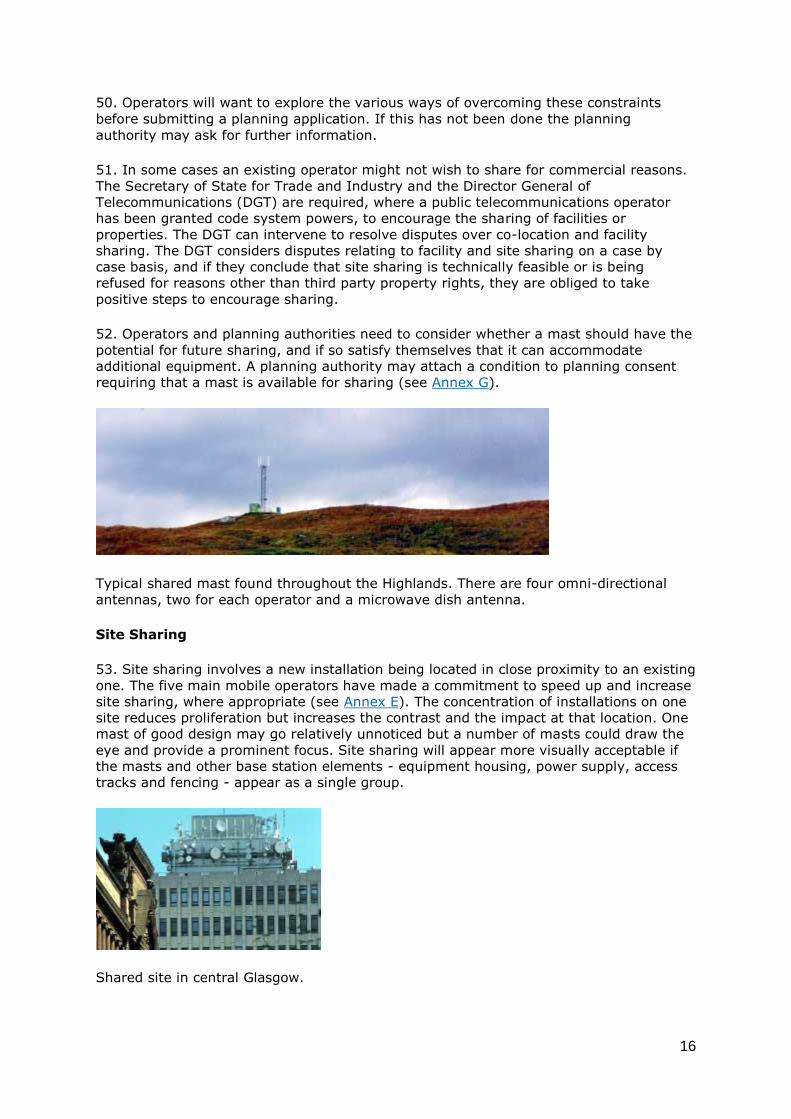
Typical shared mast found throughout the Highlands. There are four omni-directional
antennas, two for each operator and a microwave dish antenna.
Site Sharing
53. Site sharing involves a new installation being located in close proximity to an existing
one. The five main mobile operators have made a commitment to speed up and increase
site sharing, where appropriate (see Annex E). The concentration of installations on one
site reduces proliferation but increases the contrast and the impact at that location. One
mast of good design may go relatively unnoticed but a number of masts could draw the
eye and provide a prominent focus. Site sharing will appear more visually acceptable if
the masts and other base station elements - equipment housing, power supply, access
tracks and fencing - appear as a single group.
Shared site in central Glasgow.
17
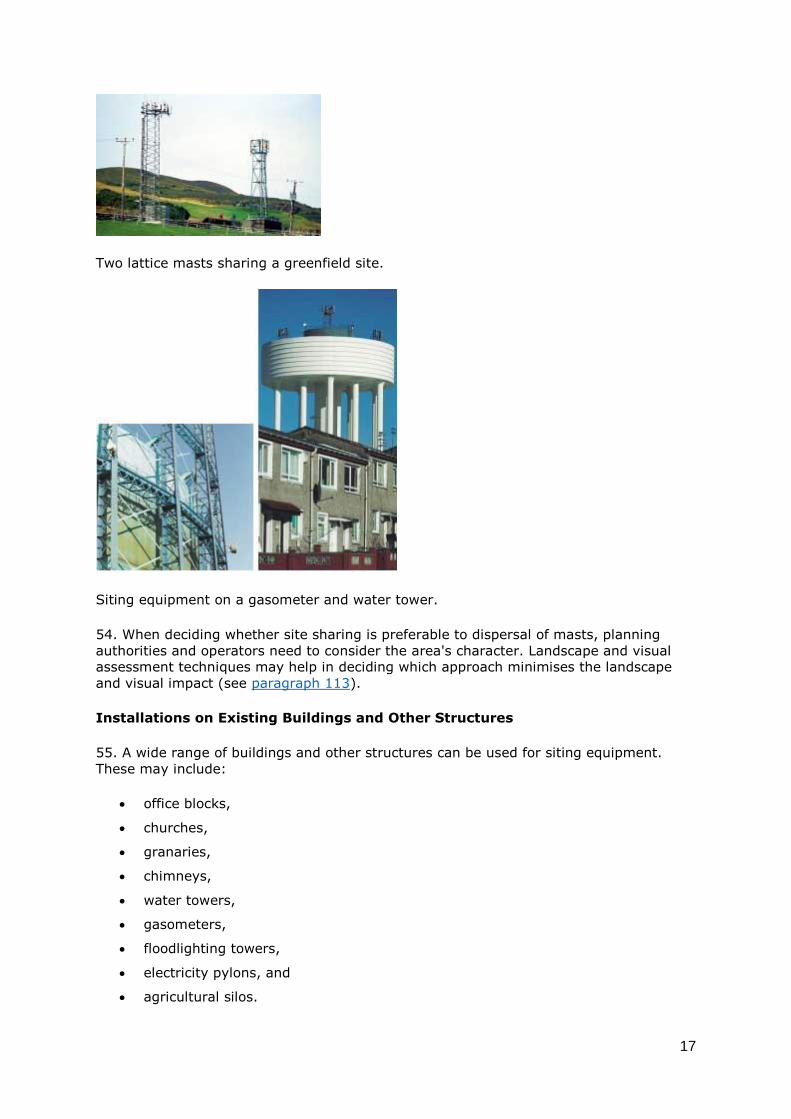
Two lattice masts sharing a greenfield site.
Siting equipment on a gasometer and water tower.
54. When deciding whether site sharing is preferable to dispersal of masts, planning
authorities and operators need to consider the area's character. Landscape and visual
assessment techniques may help in deciding which approach minimises the landscape
and visual impact (see paragraph 113).
Installations on Existing Buildings and Other Structures
55. A wide range of buildings and other structures can be used for siting equipment.
These may include:
office blocks,
churches,
granaries,
chimneys,
water towers,
gasometers,
floodlighting towers,
electricity pylons, and
agricultural silos.

18
56. The architectural style and materials used in a building or other structure will help
influence the siting and design of equipment. Buildings or other structures of historic or
architectural value will usually only be capable of accepting the installation of equipment
where it can be disguised or concealed. There may however be instances where no
installation is acceptable. Modern buildings, or buildings that already have
telecommunications equipment sited on them, may be more suited to accepting new
equipment. Architects, urban designers or specialist telecommunication design
companies can provide advice.
CASE STUDY: ELECTRICITY PYLONS
Most operators have agreements with electrcity companies to use pylons as support
structures and this is generally an excellent solution. A separate power supply is required
because the pylons carry electricity at very high levels far beyond that required.
Operators also have to obtain legal access as the electricity companies generally do not
own the land. There may be health and safety issues to resolve before a pylon can be
used.
57. The aim is that equipment on a building or other structure should:
be coloured to match the background;
be in proportion to the size of the building or structure;
relate to the architectural form;
have minimal impact on the roof line;
respect important views or skylines; and
avoid a visually damaging cumulative effect.
58. Placing equipment below a roofline or against existing rooftop structures, such as a
plant room, and painting it a matching colour often minimises the visual impact and
protects the building's silhouette. These positions may not provide exactly the same level
of radio coverage as a position above the roofline but there are often technical solutions
available to overcome gaps, such as altering the antenna mounting position or installing
more microcell antennas.
59. Positioning equipment in a group with symmetrical order will help achieve a balanced
composition. This may not be possible in all cases due to technical reasons, but
encouraging this rather than scattering equipment across a rooftop will help the various
elements appear as a single feature.
60. The use of existing buildings and other structures may be constrained by structural
limits. Many were not designed to take the additional weight and wind loading of radio
telecommunication equipment. Checking that the loading capacity can hold the proposed
installation is a matter for the operator and the building control authority. Planning

19
authorities should however be aware that load bearing levels may constrain the siting
options available to operators.
A building's silhouette can be protected through mounting equipment on the side instead
of sporadically across the rooftop. This can achieve a composition that respects the
building's design.
61. The siting of equipment on rooftops may be influenced by the need to provide an
adequate exclusion zone (see Annex B) and ensure the installation complies with the
public exposure guidelines of the International Commission on Non-Ionizing Radiation
Protection (ICNIRP).
Poor composition as the equipment is scattered across the rooftop. The various elements
have no relationship to each other and results in visual confusion. Balanced composition
through grouping equipment. The various elements appear as a single feature. Balanced
composition through symmetry. The various elements appear as a single feature.
62. NPPG19 states that for appropriate new buildings and structures (particularly larger
developments), planning authorities should encourage designs which allow new
telecommunications infrastructure to be installed within them and on them with
minimum environmental impact. This may include designing space for antenna below
parapet height, allocating space within a rooftop plant room or using radio frequency
transparent materials, such as GRP, which allows the antenna to be located behind the
façade of a building. There may also be opportunities to incorporate telecommunications
equipment sensitively into new transportation schemes, for instance by mounting
equipment on structures such as bridges, signs and lamposts. The aim is to make the
equipment appear as an integral part of the building or other structure.

20
Visual clutter caused by equipment scattered across rooftop.
Equipment and antenna housing designed to appear as an integral part of the building.
White ground based mast which contrasts with the woodland
Ground Based Masts
63. A ground based mast is the last option in the series, though that does not mean it
will not be the best solution in many situations. The design of a mast should follow the
principles outlined in paragraphs 32-33.
64. Contrast is likely to be minimised in locations that already contain engineered forms
and structures. For example industrial and commercial areas or major road junctions
where lamposts, traffic lights and road signs are present.
65. Locating a mast within an existing group of trees and/or planting new trees and
shrubs can help integrate it into the landscape. Different degrees of natural screening
can apply in summer and winter. New planting will not however be appropriate in all
landscapes. It may need to be extensive in some landscapes to avoid appearing as an
isolated block that emphasises the mast. On some exposed sites where there are no
trees and screen planting is impractical, consideration should be given to disguising the
equipment or using other landscape features to help conceal it.

21
66. Complex structures or unnatural shapes in the landscape tend to draw the eye. A
simple mast that minimises the amount of visual information will generally be perceived
as more acceptable. Slim-line monopoles appear as simple well proportioned installations
and are often a good solution. They are generally not suitable for sharing and their
overall simplicity and balanced proportion may be lost by installing additional antennas.
To support a number of antenna systems a larger mast is usually required.
67. On open exposed sites, where masts will be silhouetted against the sky, they are
often best left unpainted in a galvanised finish or painted an appropriate colour such as a
non-reflective pale grey. Where there is a backcloth of ground or trees, dark matt green
or brown is usually the most appropriate colour.
Lattice mast screened by woodland. Monopole mast painted green with two omni-
directional antennas. The visual impact would have been reduced further by painting the
antennas.
68. In complex rural landscapes with many vertical features, dispersing masts may
minimise impact. In rural landscapes devoid of vertical features concentrating masts at
one point may be preferable.
Spreading masts throughout a large open landscape may extend the impact over a wider
area than site or mast sharing. Spreading masts throughout a landscape with many
existing landscape elements may have less of an impact than site or mast sharing.
69. A mast that breaks the skyline or is sited on a prominent ridge is generally not
desirable as it creates a visual focus which draws the eye away from the natural
landscape. The ever-changing light and weather which is characteristic of Scotland can
also at times illuminate a metallic structure and increase its prominence. The best
location in many mountainous and hilly landscapes will be on the lower valley sides. This
will help provide a backcloth when viewed from the valley floor.

22
Masts in a rural area located on the valley side and painted to blend into the backcloth.
Unfortunately two masts were erected rather than sharing one and construction of an
access track was required.Lattice mast with three directional antennas. All equipment is
painted green.
70. The edges of woodlands can be particularly suitable locations for new masts. Since
plantations will ultimately be felled, new planting around the site should be provided to
ensure long-term screening. Alternatively, a section of the forestry plantation
surrounding the mast could be purchased and managed to retain screening.
Monopole mast with insert showing standard equipment housing.
OTHER BASE STATION COMPONENTS
Equipment Housing
71. Radio telecommunications equipment housing ranges in size from a small cabinet to
a purpose built hut for several operators. It can be placed within a building,
underground, on the ground or on a rooftop.
72. Equipment housing for a macrocell base station can vary in volume between
approximately 1 and 18 cubic metres. Equipment cabinets for microcell base stations are

23
usually located within adjacent buildings, or incorporated into the supporting structure,
such as the base of a lampost.
73. The equipment is connected to antennas via feeder cables. Keeping antennas and
equipment housing close to one another reduces signal loss. However, in some instances
separating the antennas and equipment housing may enable better siting, for instance
by allowing the equipment housing to be located next to an existing track. Separation
distances up to 100 metres are possible although this spacing will require a larger cable
diameter to reduce signal loss.
74. Equipment housing can be painted to blend in with its background, disguised as
street furniture, or designed as a positive feature that complements the urban
landscape. In rural areas, existing landscape features such as planting or rocky outcrops
can provide screening. New planting can also help to screen equipment housing. If
equipment housing is proposed in a sensitive location thought should be given to placing
it partially or completely underground, or to surrounding it with a well designed earth
embankment.
75. In urban areas unobtrusive locations away from principal facades, important street
frontages, prominent corner locations or any significant streetscape features are
preferable. A free standing small equipment cabinet may look better placed next to
another item of street furniture, for example a bus shelter or telephone kiosk.
76. Additional equipment housing is usually required where operators are sharing masts
or rooftop sites. Its cumulative impact needs to be considered when determining a
planning application. Additional equipment housing should be well sited and match the
colour of existing equipment housing. In sensitive locations it may be necessary for
operators to share a single building.
Equipment Compounds
77. Fencing is normally required around a mast and equipment housing. The scale of
fencing required is dependent on the location. In urban areas higher fencing may be
required, nonetheless its form and colour should be appropriate to the setting. In rural
areas there may be no need for fencing, or a post and wire fence may suffice. Security
measures should be appropriate to the circumstances.
78. The impact of an equipment compound can be minimised if the compound is not
surfaced or by using natural surface materials which match the landscape character. In
some cases the equipment can be attached directly to solid rock where it is exposed at
surface level. Any hard surfacing should be permeable and kept to the minimum
necessary.
Power Supply
79. Radio telecommunications equipment requires a power supply. This should be easily
achievable within an urban area. In remote locations however there may be no suitable
sources nearby. Often the cheapest way to provide power to a remote location is by
installing new overhead powerlines, but this will usually add to the landscape impact. In
afforested areas it will require maintenance of a clear corridor. In sensitive locations it
may be necessary to underground power supplies for all or part of their length, though
damage to habitats or archaeological sites must be minimised. Care must be taken to
ensure sensitive reinstatement of the damaged ground. Cabling has been laid directly on
the ground in such locations where no members of the public will have access.
24
80. Planning authorities should be aware that power lines are often installed by
electricity suppliers exercising their own permitted development rights. In these
situations NPPG 19 states that operators should specify suitable environmental
standards.
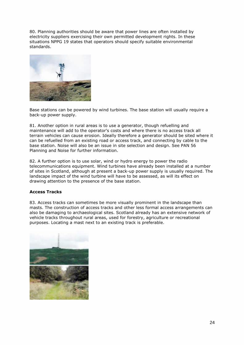
Base stations can be powered by wind turbines. The base station will usually require a
back-up power supply.
81. Another option in rural areas is to use a generator, though refuelling and
maintenance will add to the operator's costs and where there is no access track all
terrain vehicles can cause erosion. Ideally therefore a generator should be sited where it
can be refuelled from an existing road or access track, and connecting by cable to the
base station. Noise will also be an issue in site selection and design. See PAN 56
Planning and Noise for further information.
82. A further option is to use solar, wind or hydro energy to power the radio
telecommunications equipment. Wind turbines have already been installed at a number
of sites in Scotland, although at present a back-up power supply is usually required. The
landscape impact of the wind turbine will have to be assessed, as will its effect on
drawing attention to the presence of the base station.
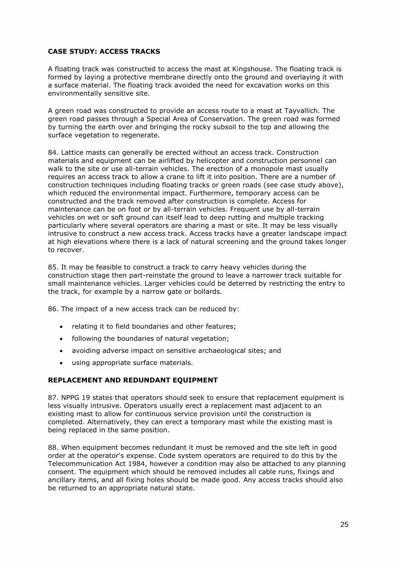
Access Tracks
83. Access tracks can sometimes be more visually prominent in the landscape than
masts. The construction of access tracks and other less formal access arrangements can
also be damaging to archaeological sites. Scotland already has an extensive network of
vehicle tracks throughout rural areas, used for forestry, agriculture or recreational
purposes. Locating a mast next to an existing track is preferable.
25
CASE STUDY: ACCESS TRACKS
A floating track was constructed to access the mast at Kingshouse. The floating track is
formed by laying a protective membrane directly onto the ground and overlaying it with
a surface material. The floating track avoided the need for excavation works on this
environmentally sensitive site.
A green road was constructed to provide an access route to a mast at Tayvallich. The
green road passes through a Special Area of Conservation. The green road was formed
by turning the earth over and bringing the rocky subsoil to the top and allowing the
surface vegetation to regenerate.
84. Lattice masts can generally be erected without an access track. Construction
materials and equipment can be airlifted by helicopter and construction personnel can
walk to the site or use all-terrain vehicles. The erection of a monopole mast usually
requires an access track to allow a crane to lift it into position. There are a number of
construction techniques including floating tracks or green roads (see case study above),
which reduced the environmental impact. Furthermore, temporary access can be
constructed and the track removed after construction is complete. Access for
maintenance can be on foot or by all-terrain vehicles. Frequent use by all-terrain
vehicles on wet or soft ground can itself lead to deep rutting and multiple tracking
particularly where several operators are sharing a mast or site. It may be less visually
intrusive to construct a new access track. Access tracks have a greater landscape impact
at high elevations where there is a lack of natural screening and the ground takes longer
to recover.
85. It may be feasible to construct a track to carry heavy vehicles during the
construction stage then part-reinstate the ground to leave a narrower track suitable for
small maintenance vehicles. Larger vehicles could be deterred by restricting the entry to
the track, for example by a narrow gate or bollards.
86. The impact of a new access track can be reduced by:
relating it to field boundaries and other features;
following the boundaries of natural vegetation;
avoiding adverse impact on sensitive archaeological sites; and
using appropriate surface materials.
REPLACEMENT AND REDUNDANT EQUIPMENT
87. NPPG 19 states that operators should seek to ensure that replacement equipment is
less visually intrusive. Operators usually erect a replacement mast adjacent to an
existing mast to allow for continuous service provision until the construction is
completed. Alternatively, they can erect a temporary mast while the existing mast is
being replaced in the same position.
88. When equipment becomes redundant it must be removed and the site left in good
order at the operator's expense. Code system operators are required to do this by the
Telecommunication Act 1984, however a condition may also be attached to any planning
consent. The equipment which should be removed includes all cable runs, fixings and
ancillary items, and all fixing holes should be made good. Any access tracks should also
be returned to an appropriate natural state.

26
Siting and Design - Area Guidance
URBAN AREAS
89. Development of radio telecommunications equipment will continue to be
concentrated in urban areas, where demand is greatest. Some existing installations in
urban areas have visually dominated residential property, busy pedestrian areas or
popular areas of open space. On the other hand, there are many examples where
sensitively sited and designed installations have been achieved.
90. Many opportunities exist in urban areas to use small scale equipment, to disguise
and conceal equipment and sensitively install equipment on buildings and other
structures. These options are considered in the siting and design general principles
section of this PAN.
91. Visually sensitive locations within urban areas where it is particularly necessary to
take positive steps to disguise or conceal equipment include:
conservation areas;
scheduled ancient monuments and their settings;
listed buildings and their settings; and
recreational areas, eg public open space.
92. Areas that already have engineered forms and structures may offer the best
opportunity for siting equipment. Less visually sensitive areas where the use of standard
equipment may be more readily acceptable include:
industrial areas;
large traffic junctions;
land adjacent to railway lines;
landfill sites;
wastewater treatment sites; and
on or near electricity pylons, water towers, floodlighting towers and gasometers.
Badly sited and designed masts can detract from principal views and skylines.

27
RURAL AREAS
93. Access to telecommunication services in rural Scotland is important for business,
educational and social use. The landscape quality of rural areas can however be easily
damaged by insensitive telecommunication installations. The impact is often heightened
because equipment can be seen over long distances. To overcome this operators are
developing creative siting and design solutions.
94. Understanding an area's landscape will help in designing sensitive proposals.
Landscape Character Assessment reports are available from Scottish Natural Heritage
(SNH). They cover the whole of Scotland and are a useful reference source. The reports
include advice on the design and siting of new developments.
95. It is best practice to avoid prominent locations visible from visitor attractions, scenic
viewpoints, or the main line of vision from a road. If unavoidable, then it is preferable
that equipment is disguised or concealed. A landscape architect can advise on:
areas to avoid;
the location with the minimum landscape impact; and
mitigation measures to reduce the landscape impact.
96. People use familiar features to gauge the scale of a landscape, but some landscapes
can seem larger than they really are because of a lack of scale indicators. A new radio
telecommunication installation could act as a scale indicator and reduce the sense of
space. Disguising and concealing techniques are appropriate for such areas. If a new
mast is unavoidable its impact can be minimised by making it slim and simple in form.
NATURAL HERITAGE
97. The key natural heritage issue will be the equipment's landscape impact. Other
important issues are -
Loss of habitat - the development of a mast may not in itself contribute to any
significant loss of habitat but consideration should be given to the associated
development of new access tracks, widening existing tracks, powerlines,
underground cables and equipment housing.
Disturbance to wildlife especially during the breeding season - construction should
be timed to avoid any sensitive periods.
Indirect habitat damage through modification of drainage patterns - this could
arise from construction activities such as cable trenching or access road
formation.

28
Earth heritage - impact on important rocks, fossils, landforms, soils and
landforming processes.
Electricity cable marker on the banks of Loch Lomond adapted to incorporate a microcell
antenna and a microwave dish.
98. There is a statutory requirement that planning authorities consult SNH on proposals
that might affect natural heritage designations. Early consultation with the planning
authority and SNH will help inform the design process. In exceptional circumstances a
planning authority may request a habitat survey or other specialist advice.
99. The effect of utilitarian structures such as masts are particularly damaging in areas
with wild land character - uninhabited and often relatively inaccessible countryside where
the influence of human activity on the character and quality of the environment has been
minimal. In these locations a mast could change a person's whole perception of the area.
If avoiding wild land is not possible equipment must be disguised or concealed. Even if a
landscape contains a road, there may be areas with wild land qualities into which it
would be inappropriate to introduce an industrial feature. Information about natural
heritage can be found in NPPG14 and PAN60.
Antennas hidden behind windows in the spire. Courtesy of The Undetectables.
HISTORIC ENVIRONMENT
100. All new equipment proposed within conservation areas or sites included within the
Inventory of Gardens and Designed Landscapes is subject to full planning control. Listed
building consent is required if an installation affects a listed building's character as a
building of special architectural or historic interest. In this respect the interior of listed

29
buildings and the curtilage of buildings can be as important as the exterior of the main
listed structure.
101. NPPG 18 sets out the Executive's planning policies in relation to the historic
environment with a view to its protection, conservation and enhancement. Advice on
installing telecommunications equipment on listed buildings and within conservation
areas is contained within section 1.10.0 of Appendix 1 of the Memorandum of Guidance
on Listed Buildings and Conservation Areas. The Memorandum is the document to which
all planning authorities are directed by Scottish Office Development Department (SODD)
Circular 13/1998 in their consideration of conservation and listed building consent
matters. It discourages the siting of equipment in areas recognised for their historic or
architectural value. It states that if no alternative is available equipment must be located
so that its visual impact is limited.
102. In historic environments consideration should initially be given to installing
equipment on any buildings with lesser architectural or historic worth. The series of
options set out at paragraph 34 is particularly applicable in historic environments.
103. All radio telecommunications development, including the siting of masts, equipment
housing, access tracks and power supplies, must be planned to avoid adverse impact on
the site and setting of scheduled monuments and other significant archaeological sites.
Appropriate archaeological mitigation strategies will be required to address impact on
sites of lesser significance. Archaeological information and advice should therefore be
sought from the relevant local authority archaeological service at the outset of site
planning, ideally as part of the pre-application discussion process. All development
affecting scheduled monuments requires scheduled monument consent under the
Ancient Monuments and Archaeological Areas Act 1979 in addition to planning consent.
Specific advice on this should be sought from Historic Scotland. NPPG 5 and PAN 42
provide further guidance on the appropriate treatment of the archaeological heritage and
on the procedures that should be followed.
CASE STUDY: GUILDFORD CATHEDRAL
The Golden Angel Weathervane on Guildford Cathedral in Surrey, a Grade II listed
building, was re-gilded by the operator and the existing support pole was replaced with
one containing antennas. The operator secured a prominent hill top site, achieved an

30
'invisible' installation and the Cathedral benefited from the restoration of an important
feature.
The Planning Framework
STRUCTURE PLANS
104. Planning policy for radio telecommunications is set out in NPPG19. The very limited
role expected to be played by structure plans is stated. This section therefore
concentrates on the other main components of the statutory planning system.
LOCAL PLANS AND SUPPLEMENTARY GUIDANCE
105. Local plan policies should be consistent with NPPG19 in allowing radio
telecommunications systems to develop subject to environmental safeguards. The
policies need to provide a clear guide for development control decisions. In doing so they
can reduce uncertainty and promote opportunities.
106. It is not possible for planning authorities to predict with much confidence where
future base stations will be needed as their siting will depend on ever changing demand
for system capacity and coverage requirements. Planning authorities can however assess
the general level of telecommunication installations in their area and ascertain whether
substantial expansion is planned. This can be done through dialogue with operators and
by examining databases of base stations ( see paragraph 115).
107. Local plans can set the standard of development expected for an area and the
criteria to be considered when determining telecommunications applications. They can
identify sensitive locations where equipment should be disguised or concealed. They can
also identify siting opportunities, such as existing base stations with the potential for site
or mast sharing or industrial or commercial areas, where more sizeable and standard
pieces of equipment may be acceptable. While locations identified in local plans will not
be capable of providing all the coverage or capacity requirements they provide a useful
reference.
108. In designated areas specified in the GPDO, such as National Scenic Areas, there are
virtually no permitted development rights. Special siting and design policies may be
needed to cover all these designated areas. Local plans may also include criteria for
installations to be treated as de minimis. Monitoring will help plans keep pace with
demand and technology.
109. NPPG19 states that if current local plans do not adequately address radio
telecommunications or where they are out of date, supplementary guidance should be
prepared quickly. It can also be prepared when a planning authority wishes to provide
more detailed guidance, for example on design or technical issues, beyond that
appropriate for a local plan.
DEVELOPMENT CONTROL
110. NPPG19 emphasises the importance of establishing good communications and trust
between operators and planning authorities. It encourages pre-application discussions on
the overall nature of an operator's network intentions and subsequently on individual
proposals. Pre-application discussions help determine where equipment can be
introduced more easily, where the environmental and operational constraints are likely
to be greatest, and the most appropriate siting and design approaches. This can avoid
unnecessary time and expense applying for planning permission on unsuitable sites or

31
submitting inappropriate designs. There are a number of suitable occasions for pre-
application discussions (see paragraphs 27-30).
111. NPPG19 encourages operators to explore alternative siting and design. Information
about these enquiries should accompany every planning application. Operators should
thoroughly explore alternative sites to find the solution with the least landscape impact,
which may help allay public concern. Where difficulties in site acquisition arise code
system operators have powers of compulsory acquisition. Although due to the time
involved in compulsory acquisition operators will generally seek another site.
112. If the consideration of alternative sites is not thought to be satisfactory the
planning authority may be justified in refusing planning permission. In such
circumstances, the authority needs to give clear reasons for refusal.
113. NPPG 19 has further information on development control including a list of
information to be submitted with a planning application. This may include further
information on the visual impact of a proposal.
The need for further information on visual impact, and the level of detail of an
assessment, will depend upon the sensitivity of the landscape and the scale of the
development proposed. In most cases a full landscape and visual impact assessment will
be excessive, instead it may be more appropriate to request a simple visual assessment.
A range of techniques can be used to assess visual impact, for instance wireline
diagrams, photomontages, zones of intervisibility, or zones of visual influence. See the
'Guidelines for Landscape and Visual Impact Assessment' produced by jointly the
Landscape Institute and Institute of Environmental Assessment.
114. The Executive is pleased to note that the Federation of the Electronics Industry
(FEI), which represents the main mobile telecommunications operators, has made ten
commitments designed to improve their practices and procedures. These include
commitments to improve the standards of community and planning authority
consultation, develop standard supporting documentation on the consideration of
alternative sites and develop agreements on mast sharing (see Annex E).
INFORMATION ON BASE STATION SITES
115. Information on existing radio telecommunications sites can be found in -
The Radiocommunications Agency radio sites database which from late 2001
gives details of all mobile base stations and their emissions (
www.sitefinder.gov.uk).
The websites of radio telecommunication site providers (eg NTL and Crown
Castle).
116. NPPG19 states that planning authorities may also find it helpful to build up a
register of sites, masts, buildings and other structures, including those which have been
previously considered but rejected.
CASE STUDY: TELECOMMUNICATIONS DEVELOPMENT DATA BASE
Dundee City Council has created a database which includes information for each radio
telecommunication enquiry and installation. The database:
facilitates the examination of planning histories of sites targeted by operators,
which assists with identifying opportunities for mast sharing; and

32
helps to speed up the processing of enquiries from operators, Councillors and the
general public by showing whether an installation has been approved, refused or
is permitted development and indicate the planning policy position.
The council has liaised with operators to ensure that the database is accurate.
Radio Interference
117. Large and prominent structures such as tall buildings and wind farms can cause
disruption to radio telecommunications services by obstructing or reflecting the signals.
The Radiocommunications Agency may be able to suggest engineering solutions to
overcome the problem, such as installing repeaters. Planning authorities can grant
planning permission for such prominent structures subject to a condition that before
development commences the developer will propose measures by which the quality of
reception affected by the proposal will be maintained.
Conclusions
118. Radio telecommunications has an important role to play in supporting the further
social and economic development of Scotland. The challenge is to ensure that radio
telecommunications development can be made an accepted and unobtrusive feature of
urban and rural areas, through high standards of siting and design and sensitive,
imaginative and creative design solutions. It is anticipated that the good practice advice
in this PAN will help improve the design quality of radio telecommunication equipment
and the confidence of planning authorities in considering planning applications.
NOTE
119. Enquiries about the contents of this Planning Advice Note should be addressed to
Ben Train, Planning Services, Scottish Executive Development Department, 2-H81
Victoria Quay, Edinburgh, EH6 6QQ (0131 244 7532) or by e-mail to
[email protected]. Further copies may be obtained by telephoning 0131 244
7538. A copy of this PAN is also available on the Scottish Executive web site at
www.scotland.gov.uk/planning
Annex A Fixed Radio Access Telecommunication Systems
1. Fixed Radio Access (FRA) systems are also sometimes known as Broadband Fixed
Wireless Access or Radio Fixed Access. These systems can be configured in two ways -
point to multipoint or point to point. (The existing FRA system in Scotland, operated by
Atlantic Telecom, is a point to multipoint system.)
2. Point to multipoint FRA systems consist of a network of base stations with antenna
pointing directly at small antenna on the connected properties. Point to point FRA
systems function by each customer receiving and transmitting data for themselves and
other neighbouring customers (see the figure below).

33
Network configuration of point to multipoint Fixed Radio Access systems
Network configuration of point to point Fixed Radio Access systems
Annex B The Exclusion Zone
Operators of any telecommunications apparatus must abide by the Health and Safety at
Work Act 1974 and the Management of Health and Safety at Work Regulations 1999.
Immediately surrounding a macrocell antenna there is an exclusion zone where the
equipment must be turned off before people can enter (these exclusion zones relate to
an area directly in front of and at the height of the antennas). Exclusion zones for
microwave dish antenna typically do not extend beyond the mouth of the dish. The
exclusion zone for picocell, microcell and FRA antenna is typically contained within the
casing. Appropriate radiofrequency safety signage should be placed in a prominent
location. The need for an exclusion zone may affect the siting of an antenna, since an
antenna cannot be located in a position where people will freely pass within the exclusion
zone.
34
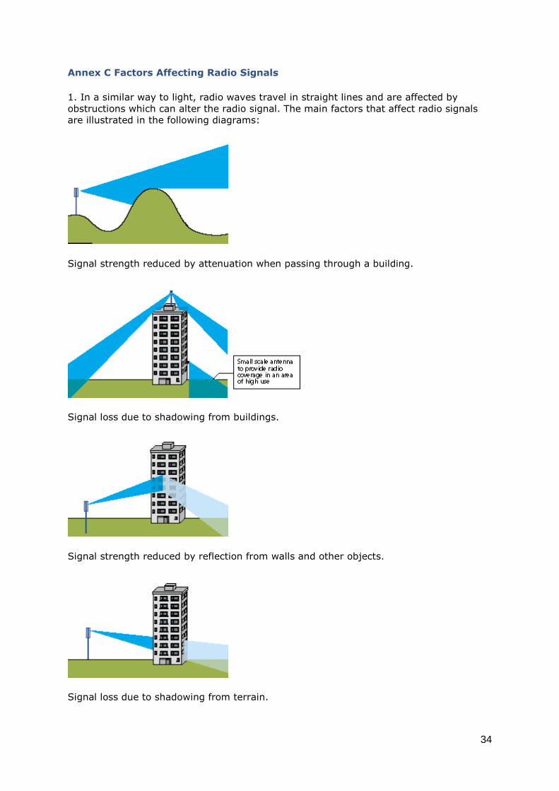
Annex C Factors Affecting Radio Signals
1. In a similar way to light, radio waves travel in straight lines and are affected by
obstructions which can alter the radio signal. The main factors that affect radio signals
are illustrated in the following diagrams:
Signal strength reduced by attenuation when passing through a building.
Signal loss due to shadowing from buildings.
Signal strength reduced by reflection from walls and other objects.
Signal loss due to shadowing from terrain.

35
Signals can 'bend' round obstructions to some extent (diffraction).
Reflection can be used to achieve radio coverage in urban areas.
2. Radio waves will penetrate certain materials such as brick, stone and steel. The level
of penetration will vary dependant upon the properties of the materials, i.e. its density
and reflective qualities. The level of penetration (depth of signal) inside buildings is an
increasingly important factor in network planning.
3. The location of transmitter antennas is important, as signals from one cell will
interfere with nearby cells on the same frequency. To avoid blind spots from buildings
and hills, antennas must usually be placed high up. In rural locations reflection by
buildings is less likely to influence site selection than in urban areas.
Annex D Code System Operator Licences and Summary of the Key Provisions of
the Telecommunications Code
1. The Telecommunications Code in Schedule 2 to the Telecommunications Act 1984
deals with the powers to install telecommunications apparatus in the street and on
private land. These powers, which are given to certain operators through the terms of
their individual licences under the 1984 Act, do not override the need for planning
permission or consents under tree preservation orders nor do they override any other
restrictions in relation to protection of the natural heritage.
2. The Code contains a number of provisions, some of which may be relevant in the
development context and these are briefly summarised below:
Paragraph 2 gives operators the right to install apparatus on private land, with
the prior agreement of the occupier.
Paragraph 3 provides that operators' activities should not interfere with or
obstruct access to other land, without the agreement of the occupier of that other
land.

36
Paragraph 5 enables an operator to go to the Courts to apply for a compulsory
order authorising it to install its apparatus on land if a person, whose agreement
is needed under the Code to place that apparatus upon that land, has refused it.
Paragraph 9 gives operators powers to carry out works in the street and install
apparatus under or over the street.
Paragraph 10 gives operators the right to fly lines over any land without the
occupier's consent (although the termination points will require consent).
Paragraph 15 enables water and sewerage authorities to make agreements with
licence holders for the placing of telecommunications apparatus in conduits within
their control.
Paragraph 17 allows for objections to overhead apparatus more than 3 metres
high by owners or occupiers of land affected.
Paragraph 18 requires an operator to fix a notice giving details of how and where
to object to the installation of such overhead apparatus.
Paragraph 19 enables an operator to require the occupier of land on which there
is a tree to lop it (but not to top or fell it), if it overhangs the street and interferes
with telecommunications apparatus.
Paragraph 20 sets out a procedure to be followed whereby an operator may be
required to alter or remove apparatus in the way of development.
Paragraph 21 sets out the restrictions on the rights of owners to require the
removal of apparatus. Where an owner is entitled to require the removal of any of
the operator's apparatus (for example at the end of a lease), they must serve a
notice on the operator requiring removal. The operator may however serve a
counter-notice within 28 days stating the steps which the operator proposes to
take for the purpose of securing a right to keep the apparatus on the land. Where
a counter-notice is given the owner may only enforce the removal of the
apparatus through pursuance of an order of the court.
Paragraph 22 states that an operator is not entitled to keep apparatus installed if
it is no longer in use and is unlikely to be used.
Paragraph 23 provides for the procedures to be followed when a local authority,
public utility or other code operator wants to alter the apparatus of a code
operator in the course of any street works. The code operator can, if he so
wishes, undertake the alteration himself or supervise the work. The expense of
alteration is borne by the undertaker who wants the alteration made.
3. The Secretary of State for Trade and Industry has power to modify code-related
conditions in licences granted under the 1984 Act, including the conditions relating to the
physical environment. Planning authorities should let the Communications and
Information Industries Directorate of the Department of Trade and Industry (DTI), (151
Buckingham Palace Road, London SWIW 9SS), know of any practical difficulties which
may be experienced with the terms of individual licences.
4. Licences can be inspected at the major offices of the code operator concerned and can
be purchased from the Office of Telecommunications (OFTEL), 50 Ludgate Hill, London
EC4M 7JJ.
Copies of licences of the local broadband cable operators will be sent to the local
authority or authorities for the locality as they are granted. Also see the DTI web site at:
www.dti.gov.uk/cii/regulatory/telecomms

37
Annex E Operator Commitments
The Federation of the Electronics Industry (FEI), representing the main mobile
telecommunications operators, has made the following ten commitments to:
1. develop, with other stakeholders, clear standards and procedures to deliver
significantly improved consultation with local communities;
2. participate in obligatory pre-rollout and pre-application consultation with local
planning authorities;
3. publish clear, transparent and accountable criteria and cross-industry agreement on
site sharing, against which progress will be published regularly;
4. establish professional development workshops on technological developments within
telecommunications for local authority officers and elected members;
5. deliver, with the Government, a database of information available to the public on
radio base stations;
6. assess all radio base stations for international (ICNIRP) compliance for public
exposure, and produce a programme for ICNIRP compliance for all radio base stations as
recommended by the Independent Expert Group on Mobile Phones;
7. provide, as part of planning applications for radio base stations, a certification of
compliance with ICNIRP public exposure guidelines;
8. provide specific staff resources to respond to complaints and enquiries about radio
base stations, within ten working days;
9. begin financially supporting the Government's independent scientific research
programme on mobile communications health issues; and
10. develop standard supporting documentation for all planning submissions whether full
planning or prior approval.
The FEI template of information to be provided with a planning application explains the
reasons why a base station is required, alternative options considered, the reasons for
the choice of design as well as relevant technical information. It has also committed
mobile operators to sending network plans to planning authorities before every major
phase and on an annual basis, during September/October (starting 2001).
38
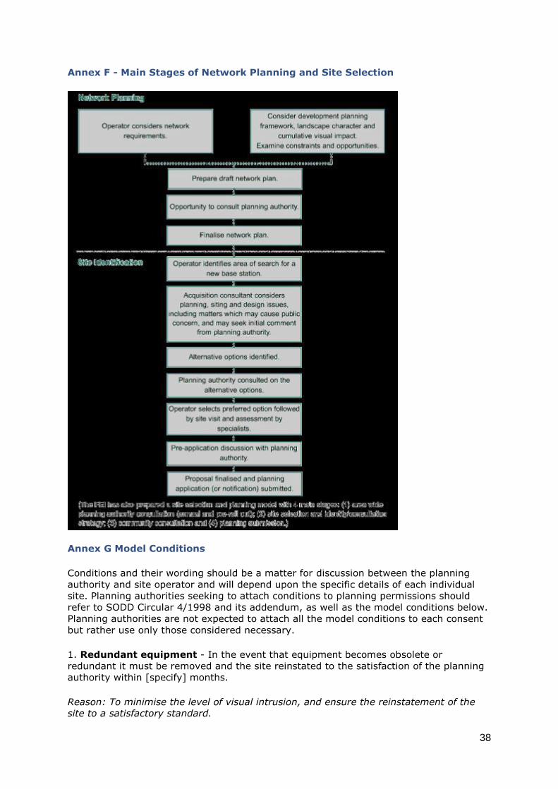
Annex F - Main Stages of Network Planning and Site Selection
Annex G Model Conditions
Conditions and their wording should be a matter for discussion between the planning
authority and site operator and will depend upon the specific details of each individual
site. Planning authorities seeking to attach conditions to planning permissions should
refer to SODD Circular 4/1998 and its addendum, as well as the model conditions below.
Planning authorities are not expected to attach all the model conditions to each consent
but rather use only those considered necessary.
1. Redundant equipment - In the event that equipment becomes obsolete or
redundant it must be removed and the site reinstated to the satisfaction of the planning
authority within [specify] months.
Reason: To minimise the level of visual intrusion, and ensure the reinstatement of the
site to a satisfactory standard.

39
2. Redundant equipment on buildings - In the event that equipment is removed from
the building for any reason, all cabling, fixings and ancillary items shall be removed and
all fixing holes made good to the satisfaction of the planning authority within [specify]
months of the date on which the equipment is removed.
Reason: To minimise the effect on the fabric of the [listed] building, and ensure the
reinstatement of the site to a satisfactory standard.
3. Access tracks - The land required for the access track proposed to enable
construction of the base station, mast structure and ancillary developments, shall be
fully reinstated to an agreed condition, immediately following completion of the
construction works to the satisfaction of the planning authority.
Reason: To minimise the level of visual intrusion, and to protect the quality and
character of [specify] as far as practicable.
4. Power supply - Development shall not be commenced until such time as it has been
demonstrated to the satisfaction of the planning authority that the power line required to
serve the proposed base station, mast structure and ancillary developments shall be
constructed underground with no electricity poles or other structures relating to the
proposed new power line linking to the site being visible above ground [from X to Y].
Reason: To minimise the level of visual intrusion and protect the quality and character of
[specify] as far as practicable.
5. Fencing - Development shall not be commenced until such time as the written
approval of the planning authority has been obtained in respect of the details of any
boundary fencing or other form of enclosure and the approved works shall thereafter be
implemented and maintained to the satisfaction of the planning authority.
Reason: To minimise the level of visual intrusion and protect the quality and character of
[specify] as far as practicable.
6. Colour - The detailed specification of all the elements including the support structure,
associated equipment housing cabinets, antennas and cabling shall be approved by the
planning authority prior to their construction and shall not be altered thereafter unless
agreed in writing.
Or - Upon installation, the mast, fencing cabin and all other related equipment, fixtures
or fittings shall be coloured [specify] and thereafter they shall be maintained as such, to
the satisfaction of the planning authority.
Reason: To minimise the level of visual intrusion and protect the quality and character of
[specify] as far as practicable.
7. Advertising - No symbols, sign, logos, or other lettering shall be displayed on any
part of the structure, antennas, equipment housing or fencing without the prior written
approval of the planning authority, except small signage necessary for operational
reasons.
Reason: To minimise the level of visual intrusion and protect the quality and character of
[specify] as far as practicable.
8. Mast sharing - The mast shall be structurally capable of being shared by additional
radio telecommunication equipment.

40
Reason: To enable potential mast sharing.
9. Lighting - The site shall not be illuminated by lighting without the prior written
approval of the planning authority.
Reason: To minimise the level of visual intrusion and protect the quality and character of
[specify] as far as practicable.
10. Landscaping - See addendum to Circular 4/1998 which contains some examples of
model conditions relating to landscaping.
Glossary
Antenna - A passive electrical component which can transmit and receive radio waves.
Attenuation - Reduction in strength of a radio signal as a result of atmospheric
absorption, obstruction by buildings etc.
Base Station - A fixed radio transmitter/receiver which electronically relays signals to
and from handsets and other data terminals. Generally taken to include all the
component of the development - the antenna, mast or supporting structure, equipment
housing, cable runs, fencing, planting, landscaping, access, power supply and land lines.
Broadband - a service or connection allowing a considerable amount of information to
be conveyed, such as television pictures. Generally defined as a bandwidth greater than
2Mbits per second.
Code System Operator - An operator of a telecommunications system under Schedule
2 of the Telecommunications Act 1984, known as the "Telecommunications Code".
Convergence - denotes the meeting of separate communications technologies so that
they no longer have unique associations with particular functions. For instance, an
internet television can combine some of the functions of a radio, television, personal
computer and telephone (source DTI).
De minimis - This term covers minor works which, in relative terms, may not have a
material effect on the external appearance of the building or structure on which they are
installed. As a result they may not come within the legal definition of development and
hence not require planning permission, though listed building consent may still be
required.
Directional antenna - Any antenna which picks up or radiates antenna signals better in
one direction than another.
Director General of Telecommunications - see OFTEL.
FRA - Fixed Radio Access - A low power radio system for connecting individual
subscribers in buildings to a base station. See small antenna.
GPRS - General Packet Radio Service. A system which transmits information in short
bursts and is therefore suited to internet services. It can carry live video though it does
not have the full facilities offered by 3G systems.
Ground Based Mast - a mast constructed on the ground either directly or on a plinth or
other structure constructed for the purpose of supporting the mast.

41
GRP - Glass Reinforced Plastic.
GSM - Global System for Mobile Communications or Groupe Speciale Mobile - the second
generation digital mobile technology used in Europe and other parts of the world.
ICNIRP - International Commission on Non-Ionizing Radiation Protection. Responsible
for co-ordinating knowledge of protection against the various non-ionising radiations. It
works closely with organisations of the United Nations including WHO, ILO and UNEP.
Strong support is received from the Commission of the European Communities. Work
encompasses environmental health criteria on different aspects of non-ionizing radiation.
Set up by the International Radiation Protection Association. ( www.icnirp.de)
OFTEL - Office of Telecommunications (the UK telecommunication watchdog). A
government department which acts as telecommunications regulator but is independent
of ministerial control. It is headed by the Director General of Telecommunications, who is
appointed by the Secretary of State for Trade and Industry. The DTI Communications
White Paper proposes the creation of a new regulator called the Office of
Communications ( OFCOM). It will combine the existing functions of the Broadcasting
Standards Commission, Independent Television Commission, OFTEL, the Radio Authority,
the Radiocommunications Agency and possibly the video classification function carried
out by the British Board of Film Classification.
Omni-directional antenna - Antenna that radiates or receives signals equally well from
all directions.
PSRCP - Public Safety Radio Communications Project, known as the Airwave service. A
digital radio telecommunication service being developed for the emergency services.
Roaming - Roaming agreements allow a customer of one mobile operator to use
another mobile operator's network to make or receive a call - usually because the
customer is out of range of their own network. Two of the existing operators (Vodafone
and BT Cellnet), accepted modifications to their licences to allow the new entrant
(Hutchison 3g 1) to roam on their networks until 2009, although it is not anticipated that
this will be used. At present there is no roaming between operators in the UK.
Small Antenna - An antenna for use in connection with a telephone system operating
on a point to fixed multi point basis, which does not exceed 50 cm in any linear
measurement and does not, in two dimensional profile, have an area exceeding 1,591
sq. cm. (see GPDO)
Transmitter - Electronic equipment which generates radio frequency electromagnetic
energy and is connected to an antenna.
TACS - Total Access Communications System.
TETRA - Terrestrial Trunked Radio.
UMTS - Universal Mobile Telecommunications System.
3G - Third Generation of mobile telephony technology which uses broadband radio to
carry large amounts of data.
1Hutchison 3g is due to be rebranded in late 2001.