planning of a production layout for a swedish
TRANSCRIPT
Title
1
Planning of a Production layout for a Swedish manufacturing company
PAPER WITHIN Master Thesis
AUTHOR: Akshay Deepak Shettennavar
Prajwal yadav prasanna kumar
TUTOR: Melina Ettehad
JÖNKÖPING June 2021
A case study at REHOBOT Rotex AB

2
This exam work has been carried out at the School of Engineering in Jönköping in the
subject area of Production system with a specialization in production development and
management. The work is a part of the Master of Science program.
The authors take full responsibility for the opinions, conclusions, and findings
presented.
Examiner: Gary Linnéusson
Supervisor: Melina Ettehad
Scope: 30 credits (second cycle)
Date: 01-06-2021

Acknowledgement
3
Acknowledgement
We would like to thank all the people who have helped us to finish the Master's thesis.
Firstly, we would take this opportunity to thank our supervisor Melina Ettehad for all
the support and guidance provided by her. Her feedback and comments have helped us
in writing and completing the thesis.
We also want to thank the case company, REHOBOT Rotex AB, for the opportunity to
conduct the study in collaboration with them. A special thanks to our supervisor Joel
Alexanderson (CEO) at REHOBOT Rotex AB, for the continuous support and help.
Jönköping, June 2021

Abstract
4
Abstract
Plant layout is the heart of any production line because if the layout is not properly laid,
there can be numerous consequences. Planning a layout for an SME is the most crucial
and tedious job for a manufacturer because it is time-consuming and sometimes a costly
process. Therefore, there is a need to choose appropriate methods to overcome certain
problems and plan a good layout for the SMEs. The purpose of this thesis report is to explore methods that can help to plan the layout
according to the requirements provided by the SME. This involves a detailed study
conducted to understand the processes at the case company. However, change of layout
is not just making changes to the existing layout, but some SMEs must plan a
completely new layout where they can start from scratch. Similarly, in this case, a
Swedish manufacturing company REHOBOT Rotex AB has provided all the data
required for planning the layout. This leads the authors to study the entire production
flow to know the current layout and identify the problems that exist in the plant. The
approach of this thesis was a case study where the company has provided all the details
like documents, current layout plans, and video recording of the plant. The study shows that maximum time is spent in the replenishment of storage and
unnecessary movement of materials between the machines in the current facility. These
activities can be classified as Nonvalue added or just can be addressed as waste.
Therefore, there is a need to implement lean tools and use the SLP method to plan the
new layout systematically. This method led to form alternative layout plans that
consisted of changes made depending on the current layout. These changes will fetch
the advantages and disadvantages that can further help in evaluating the alternatives
using WFA. Once evaluated, the layout that turned out to be the best will be suggested
and presented to the case company. Keywords:
Layout planning, Lean, Systematic layout planning, 8 waste, 5S, Visual Management,
material handling, and material flow.
Abbreviations:
SME – Small and medium-sized enterprises
SLP- Systematic Layout Planning
NVA- Non-value Added
NNVA- Necessary but Non-Value-Added
VA- Value Added
WFA- Weighted Factor Analysis

Table of Content
5
Table of Contents
1 Introduction .............................................................................. 9
1.1 BACKGROUND ......................................................................................................................... 9
1.2 COMPANY BACKGROUND ........................................................................................................ 9
1.3 PROBLEM DESCRIPTION ......................................................................................................... 10
1.4 AIM AND RESEARCH QUESTION ............................................................................................. 10
1.5 DELIMITATIONS ..................................................................................................................... 11
1.6 OUTLINE ................................................................................................................................ 11
2 Theoretical Background ......................................................... 13
2.1 LAYOUT PLANNING ............................................................................................................... 13
2.2 SYSTEMATIC LAYOUT PLANNING (SLP) ................................................................................ 15
2.3 MATERIAL HANDLING ........................................................................................................... 17
2.4 LEAN PRODUCTION ................................................................................................................ 21
2.5 WEIGHTED FACTOR ANALYSIS ............................................................................................... 24
2.6 FISHBONE DIAGRAM .............................................................................................................. 25
3 Method and Implementation ................................................. 27
3.1 RESEARCH DESIGN ................................................................................................................. 27
3.2 LITERATURE REVIEW ............................................................................................................. 27
3.3 BRAINSTORMING ................................................................................................................... 28
3.4 CASE STUDY RESEARCH ......................................................................................................... 29
3.5 SYSTEMATIC LAYOUT PLANNING (SLP) PROCEDURE ............................................................ 33
3.6 WEIGHTED FACTOR ANALYSIS (WFA) ................................................................................... 39
3.7 RESEARCH QUALITY .............................................................................................................. 42
4 Findings .................................................................................... 44
4.1 CURRENT STATE .................................................................................................................... 44
4.2 PARAMETERS OF THE FUTURE FACILITY ................................................................................ 51
5 Analysis .................................................................................... 53
5.1 FUTURE STATE MAPPING USING SLP ..................................................................................... 53

Table of Content
6
6 Discussion ................................................................................ 72
6.1 DISCUSSION OF METHODS ...................................................................................................... 72
6.2 DISCUSSION OF FINDINGS AND ANALYSIS .............................................................................. 73
7 Conclusion ............................................................................... 79
7.1 RECOMMENDATIONS .............................................................................................................. 80
7.2 FUTURE SCOPE ...................................................................................................................... 81
8 References ............................................................................... 82
9 Appendices .............................................................................. 87

List of tables
7
List of Tables
Table 1: The Literature search. ................................................................. 28
Table 2: survey questions for employees. ................................................. 31
Table 3: Survey responses from the employees. ...................................... 32
Table 4: Closeness Relationship Values ................................................... 35
Table 5: Closeness Relationship Values ................................................... 36
Table 6: Weighted factor analysis method of evaluation ......................... 41
Table 7: Rating Code and Values ............................................................. 41
Table 8: Weighted factor analysis of the current facility. ........................ 48
Table 9: Rating code and Values .............................................................. 48
Table 10: Challenges in case company compared to challenges in literature.
................................................................................................................... 58
Table 11: Challenges in case company compared to improvements in
literature. ................................................................................................... 59
Table 12: A list of advantages and disadvantages of the alternative layouts.
................................................................................................................... 68
Table 13: Weighted factor analysis of the alternative layouts. ................ 69
Table 14: Rating codes and Values .......................................................... 70
Table 15: Difference between the alternative Layouts ............................. 75
Table 16: Difference between the current layout with the cause and the
future layout with the solution. ................................................................. 76
Table 17: Difference in Weighted factor analysis between the current
layout and the future layout. ..................................................................... 77

List of figures
8
List of figures
Figure 1: Classification of facility planning ............................................. 13
Figure 2: Product type layout.................................................................... 14
Figure 3: Four steps used in the SLP approach. ....................................... 16
Figure 4: Fishbone Diagram ..................................................................... 26
Figure 5: SLP procedure ........................................................................... 34
Figure 6: Activity Relationship Chart ....................................................... 35
Figure 7: Activity Relationship Diagram ................................................. 36
Figure 8: Space Relationship Diagram ..................................................... 38
Figure 9: Alternative Block Layouts ........................................................ 39
Figure 10: Current production layout ....................................................... 45
Figure 11: Current operations ................................................................... 46
Figure 12: Fish bone Diagram. ................................................................. 49
Figure 13: Future Facility ......................................................................... 52
Figure 14: Flowchart illustrating the Material Flow from Raw material
storage to Finished Product storage .......................................................... 53
Figure 15: Future Activity Relationship Chart between the operations. .. 54
Figure 16: Future Activity Relationship Diagram .................................... 55
Figure 17: Future Space Relationship Diagram ....................................... 57
Figure 18: First alternative layout. ............................................................ 65
Figure 19: Second alternative layout. ....................................................... 66
Figure 20: Third alternative layout. .......................................................... 67

Introduction
9
1 Introduction
1.1 Background
Small and medium-sized enterprises (SMEs) are under pressure to improve their output by lowering costs and increasing productivity because of increased market competition. The one element that enables the growth of the productivity and efficiency of the layout is the establishment of a well-planned layout (Ali Naqvi et al., 2016). The layout of the facility affects the cost of production and the productivity of the SME. If there is a difference in the layout of the plant and the way materials are moved and treated, it can decrease productivity. In order to meet customer satisfaction and demand, it is very important to have a stable flow of material in the plant (Drira et al., 2007). For a factory, there are four different types of planning cases. The first planning case is planning a new factory called the Green field project which means a new building is going to be built in an unbuilt property. The second case is called the Brown field project, where the existing building is restructured, and a part of it is renovated. The existing building has a current production phase which has to be redesigned. The third case is the revitalization of the existing empty buildings, a type of Brown field project. The fourth planning case is the removal of existing facilities (Hoernicke et al., 2015). Production line planning is part of the organization's long-term planning process. An SME’s performance is influenced significantly by layout planning. The layout planning of the SME should fulfill some basic requirements like available space, a number of operators and machines, and productivity aspects. It should be able to adjust to changes once the factory is planned and constructed. This is an important factor to be considered before constructing the actual plant. Planning a layout can be done using various methods such as SLP and Computer programming. The SLP method is interesting and uses basic steps for planning the layout of the SMEs (Watanapa & Wiyaratn, 2012). Thus, this thesis will use the SLP method to plan the layout for the case company. The Lean Manufacturing approach has become part of the organization's competitive strategy, offering productivity enhancements that seek to minimize costs, increase resource availability, increase efficiency and reduce waste (Campos et al., 2016). The aim of manufacturing companies in implementing lean methodology requires them to find new ways to recognize and reduce waste. Therefore, implementing Lean in the Production flow will significantly increase the plant's productivity by using some common tools like eight wastes, just in time, Kanban, and 5S (Shah & Ward, 2007).
1.2 Company Background
This project is carried out in collaboration with REHOBOT Rotex AB. Rotex AB is a Swedish manufacturing company based in Partille. It produces turned parts in tiny dimensions since 1947. The materials used in their production are Brass, Steel, and Stainless steel. The size of the turned parts is a diameter of 2 – 16 millimeters. A broad range of products is used in many different areas such as electronics, telecom, fasteners, locks, and many others. The company has become successful both locally and internationally. The market is primarily in Sweden and exports to Norway, Finland, Denmark, Latvia, Poland, Netherlands, Germany, Czech Republic, and Israel. The plant produces nearly 15 million parts per year. The company has employed about ten people distributed in various departments such as administration, production, packaging, and maintenance. The focus of this thesis report is on the shop floor, which employs six

Introduction
10
people. Overall, the company consists of 62 machines used in production, placed in two different facilities. The current plant capacity is 1500 square meters. The capacity of the new facility is 3000 square meters.
1.3 Problem Description
REHOBOT Rotex AB's facility in Partille is currently in a transitional period, with the
existing manufacturing plant is set to be relocated to a new facility close to the current
facility. Present facility stores and manages all kinds of items, including machines,
inventory, electronic locks, tools, and safety equipment which will be relocated to a
new facility. In the future, this will lead to a considerable decrease in productivity.
Many small and medium-sized companies are seeking to develop a production flow that
concentrates greatly on material handling effectiveness, storage effectiveness, safety,
and flow of materials. It is evident that relocating is not an easy job for any company,
and it is an even costlier process to do if there is no appropriate plan. REHOBOT Rotex
AB is one of those SMEs that might suffer from such a problem. Thus, their focus is
to develop an effective layout that can be integrated into the new facility. The case
company knows the risks of relocating, and therefore they have asked the researchers
to conduct a thorough study and plan the best layout, which will enhance the
performance in the new facility compared to their existing plant layout.
1.4 Aim and Research Question
This research aims to plan a production floor layout while using systematic layout
planning (SLP) as a method. This can be done by implementing a better material
handling system and lean manufacturing tools to eliminate waste. Hence, the purpose
of this research is to plan a potential layout for the future plant that can be incorporated
within the future facility.
Research questions
Globally, industries are facing new challenges to improve their production to meet the market demand. Thus, it is crucial for a manufacturer to have the best production layout for which a study of the existing one needs to be done to find out the challenges faced. Hence this is followed by the first research question for the topic. RQ 1: What are the challenges faced in the current layout? This question will be answered in the findings chapter after a thorough study of the data and documents collected from the company. Once the challenges have been identified, few alternative layout plans are made depending on the company requirement. One of the plans is implemented, which will satisfy the requirements of the company. Hence this brings us to the second research question for our topic.

Introduction
11
RQ 2: Which is the best layout among the alternatives? After developing alternative layouts, one of the best alternatives must be selected to be implemented in the future facility. It is now time to analyze the alternatives by comparing them with each other. Out of these alternatives, one layout will be selected for the implementation as a future layout. Thus, the second research question will be answered in the analysis chapter. A comparison should be made between the two to show that the planned layout is more effective than the current layout. This process can explain why the future layout is better than the current layout. Thus, this will lead to the third research question. RQ 3: What are the differences between the current layout and the future layout? Lastly, the third research question that will help is discovering all the differences between current and future layout plans. These differences will show the effectiveness of the future layout plan when compared to the current layout plan. Thus, a detailed answer to this question will be provided in the discussion chapter.
1.5 Delimitations
This report will mainly focus on production layout planning with effective material
flow. Due to the limited time constraints and the present COVID-19 situation, the
detailed layout plan will not be part of this thesis report. The cost of implementing the
planned layout will not be included in this report. This paper will only provide a general
layout plan as a recommendation, but implementing the layout plan will be the
company's decision. Hence implementing the layout will also not be a part of this thesis
report. The challenges faced when relocating the facility will also not be a part of this
report.
1.6 Outline
This thesis report is divided into the following five chapters: Introduction, Theoretical Background, Methods and implementation, Findings and Analysis, Discussion and Conclusion. Chapter 1: Introduction. This chapter introduces the topic of research, including the purpose of the study and the relevant research questions. It also provides the limitations of this thesis report. Chapter 2: Theoretical background. This chapter describes the findings of the literature through an extensive literature review on Layout Planning, Systematic Layout Planning (SLP), material handling systems, and Lean Production. The theoretical background serves as a basis for identifying information in the literature relevant to the research topic. Chapter 3: Method and implementation. This chapter outlines the research design and methodological tools used to answer the research questions in this thesis report. Finally, the quality of the research is evaluated.

Introduction
12
Chapter 4: Findings and Analysis. This chapter contains all the data collected on the different aspects of the existing production system. It also provides the analysis of the current production based on the theories presented in the Theoretical background. Chapter 5: Discussion and Conclusion. This chapter provides a discussion of the analyzed findings concerning the literature. At the end of the report, the conclusions are drawn from the previous chapters.

Theoretical Background
13
2 Theoretical Background This section of the report provides the theoretical context based on the topic of research. It explains the necessary strategies and principles that will help analyze the case company's empirical data.
2.1 Layout Planning
Factory layout planning is important for SMEs when designing or redesigning
production systems (Febriandini & Yuniaristanto, 2019). Layout planning is an
essential task for the SME to overcome many challenges. Usually, when the SME starts
to plan the layout, it needs to focus upon aspects such as the desired design, shape,
number of workers, available space, and the machine's activities (Mikhail & Sadllah,
2020). The Layout refers to the arrangement and location of the manufacturing cell
where productions of products and services are carried out. The SME’s layout arbitrates
the material flow and services in a facility to reduce the time required for transportation
and overall production. Therefore, it is very important to have an efficient layout plan
that helps in improving production goals. Further, it also ensures a smooth flow of
information, goods, and people on the shop floor (Suhardini et al., 2017).
Planning the Layout is a tedious task because of two major problems: the facility's
restrictions and enabling a smooth material flow. There can be many problems that can
occur during layout planning which are most often related to location and types of
machines used. A good Layout plan includes a combination of the most effective
interaction of different installations such as production units and material handling
systems (Drira et al., 2007). Kulkarni (2015), further argued that some aspects need to
be considered for the layout planning, and that can be classified into as shown in Figure
1:
Figure 1: Classification of facility planning modified from (Kulkarni et al., 2015)
Factory planning
Plant design
Structural design
layout plan
SLP
Handling system design
Plant location

Theoretical Background
14
• Plant location: Selection of plant layout is a crucial task as it involves choosing
an area that is close to customers, suppliers, and other related facilities that are
required during the production (Kulkarni et al., 2015).
• Plant design: This is related to the architectural design of the building and the
utilities of the plant where the production of goods is going to take place
(Kulkarni et al., 2015).
• Layout plan: To maximize the production process's productivity and efficiency,
it is very important to develop a broad understanding of the layout. During
layout planning, it involves placing all the machinery and equipment in the right
places and creating workstations for these machinery where people can have
enough space to work freely (Kulkarni et al., 2015).
• Maintaining design: Once the layout is done, the final task is to maintain the
layout that includes management of materials, information, and machinery
placed in the layout (Kulkarni et al., 2015).
SMEs have many reasons for their purpose to change the layout. Whenever a new
project has arrived, manufacturers tend to change the existing layout or plan a new
layout for the entire facility. Although SMEs have many reasons for their decisions,
several factors are considered even before implementing any change in the layout plan.
Brattberg (2018) states some of the factors as follows: the flow of material, proper
utilization of space, proper management rules, ease to employees, maintenance, and
closeness of layout (Brattberg & Mathew, 2018). Failure to satisfy these factors will
result in an improper layout. This will eventually cost a lot for the company in terms of
time, productivity, and money. These factors have been formulated to improve
flexibility, reduce material handling cost, reduce lead time, and better usage of space
(Pratami et al., 2017).
The task of layout planning also depends on the type of machines and departments that
the organization requires to satisfy production needs. Planning a layout can either be
done for a manually operated factory a fully automated factory; no matter what type of
factory it is, planning the layout remains the same (De Carlo et al., 2013).
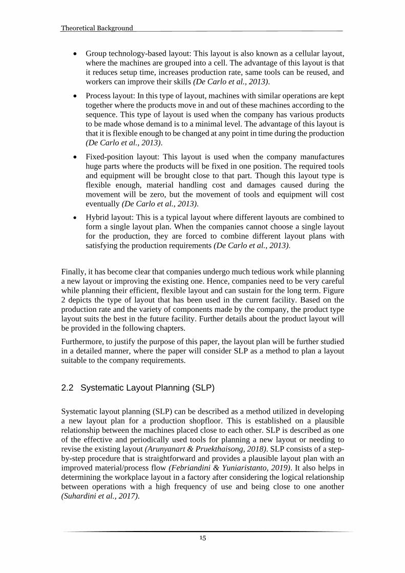
According to De Carlo (2013), there are five types of layouts as follows:
• Product layout: This type of layout is suitable if the company plans for mass
production where the machinery should be placed in a sequence. This layout has
many advantages such as reduced material handling cost, less process time,
flexibility, planning, and control will be easy. This process can be clearly
understood with the help of Figure 2 (De Carlo et al., 2013).
Figure 2: Product type layout
Turning Milling Drilling Assembly Inspection Packaging
Theoretical Background
15
• Group technology-based layout: This layout is also known as a cellular layout,
where the machines are grouped into a cell. The advantage of this layout is that
it reduces setup time, increases production rate, same tools can be reused, and
workers can improve their skills (De Carlo et al., 2013).
• Process layout: In this type of layout, machines with similar operations are kept
together where the products move in and out of these machines according to the
sequence. This type of layout is used when the company has various products
to be made whose demand is to a minimal level. The advantage of this layout is
that it is flexible enough to be changed at any point in time during the production
(De Carlo et al., 2013).
• Fixed-position layout: This layout is used when the company manufactures
huge parts where the products will be fixed in one position. The required tools
and equipment will be brought close to that part. Though this layout type is
flexible enough, material handling cost and damages caused during the
movement will be zero, but the movement of tools and equipment will cost
eventually (De Carlo et al., 2013).
• Hybrid layout: This is a typical layout where different layouts are combined to
form a single layout plan. When the companies cannot choose a single layout
for the production, they are forced to combine different layout plans with
satisfying the production requirements (De Carlo et al., 2013).
Finally, it has become clear that companies undergo much tedious work while planning
a new layout or improving the existing one. Hence, companies need to be very careful
while planning their efficient, flexible layout and can sustain for the long term. Figure
2 depicts the type of layout that has been used in the current facility. Based on the
production rate and the variety of components made by the company, the product type
layout suits the best in the future facility. Further details about the product layout will
be provided in the following chapters.
Furthermore, to justify the purpose of this paper, the layout plan will be further studied
in a detailed manner, where the paper will consider SLP as a method to plan a layout
suitable to the company requirements.
2.2 Systematic Layout Planning (SLP)
Systematic layout planning (SLP) can be described as a method utilized in developing
a new layout plan for a production shopfloor. This is established on a plausible
relationship between the machines placed close to each other. SLP is described as one
of the effective and periodically used tools for planning a new layout or needing to
revise the existing layout (Arunyanart & Pruekthaisong, 2018). SLP consists of a step-
by-step procedure that is straightforward and provides a plausible layout plan with an
improved material/process flow (Febriandini & Yuniaristanto, 2019). It also helps in
determining the workplace layout in a factory after considering the logical relationship
between operations with a high frequency of use and being close to one another
(Suhardini et al., 2017).

Theoretical Background
16
Finding the best production layout that meets all the essential organizational needs is
difficult for SMEs. Several methods are listed in various scientific papers that can assist
and direct organizations during the planning and implementation phases of their
layouts. The SLP method is one of the most popular frameworks identified in the
literature (Pratami et al., 2017). Richard Muther, developed a technique for facility
layout planning called SLP. According to Muther and Hales (1981), SLP is defined as
“an organized way to conduct layout planning” (Muther & Hales, 1981).
For more than three decades, SLP technology has been commonly applied in the
industry due to its simple step-by-step plan approach (Muther & Hales, 1981). The SLP
framework emphasizes a high rate of material flow at a low operational cost, as well as
minimal material handling (Pratami et al., 2017). It is an excellent layout planning
method for small and medium-sized companies (Shivam Singh & Khanduja, 2019).
Therefore, SLP is the most commonly used approach for creating an efficient layout
(Zakirah et al., 2018). The step-by-step approach of SLP is shown in Figure 3.
Figure 3: Four steps used in the SLP approach.
Step 1: Deciding the layout of the building where departments will be organized.
Among these four phases, this is the simplest. The planner must determine where the
departments will be positioned.
Step 2: General overall layout should be established. In this phase, several tasks include
the determination of material flow, the affirmation of special equipment beside each
other, determining the space for each department, balancing the available space, and
the creation of up to five plant layout proposals.
Step 3: Creating a detailed layout plan. Complete details are given for the chosen layout
from Step 2. These details include vehicles, machinery, support facilities such as
offices, break rooms, toilets. In the end, the details must be approved by the
management.
Step 4: Implementing the selected layout.

Theoretical Background
17
Step 2 will be discussed in the methods chapter since it is more critical than Steps 1 and
4 for planning the facility. Step 3 follows the same procedure as Step 2, except for more
detailed planning of each department.
After using the SLP method to plan the layout, it is important to include the material
handling and lean aspects into the plan. This will help in increasing the productivity of
the layout (Pratami et al., 2017).
2.3 Material Handling
Material handling can be defined as the process where the materials required for
production are moved, controlled, protected, and stored. This process is very important
as the material should be handled carefully without any damage and delivered to the
destination with desired quality and condition (Ondiek, 2005).
Accidents may be minimized or avoided when a proper material handling system is in
place, and stress and efforts may also be reduced. Material handling should always be
taken seriously because accidents could occur when a large amount of material is
moved. Different kinds of methods, tools, and equipment are used to do it efficiently
and safely. Material handling is necessary for any human activity that involves
materials (Ioannou, 2007). On the other hand, material handling is a term used in the
field of engineering and technology to describe industrial production. Materials must
be handled as raw materials in every large or small industry involving manufacturing
work. The material handling system can be as broad as an industry because of the need
for an optimized design and implementation unique to various types of industries. There
has been no proper definition of material handling; many authors have attempted to
define it. According to the American Material Handling Society, “Material handling is
the art and science involving the moving, packaging and storing of substances in any
form” (Ray & Sidharatha., 2019).
2.3.1 Types of Material Handling
Material handling is performed both internally and externally, i.e., internal and
external material handling systems. The internal material handling system consists
of moving, storing, tracking, and protecting the material inside the facility so that it
can be provided at the time and place needed. External material handling systems
involves the movement and tracking of materials from external storage to the
facility (Ray & Sidharatha., 2019).
Manual Material Handling system : Manual material handling is carried out
manually and is common in most manufacturing companies. The advantage of using
this system is the flexibility and reduced cost when handling materials of a
lightweight compared to equipment and machines. However, the downside of
Manual Material Handling is that if carried out improperly or if the materials are
too heavy, workers could be injured. Manual Material Handling is the major cause
of musculoskeletal disorders and lower back pain among workers. According to
some authors, bad work postures and techniques may lead to musculoskeletal

Theoretical Background
18
disorders. Poorly performed Manual Material Handling, especially manual lifting,
is the main cause of injuries among industrial workers. One of the main reasons for
these issues and accidents is performing repetitively loading for a long period
(Deros et al., 2015).
Material Handling Equipment: Material handling is carried out using forklifts,
trucks, overhead cranes, and conveyors. Few of the equipment is fixed, and few are
flexible where few use floors, and few use the space over the machines. Material
handling equipment is planned to minimize contact between operators and the
physical movement of goods. Thus, material handling equipment is an efficient,
accurate, and timely process of moving materials in a production environment
(Cronin et al., 2020).
2.3.2 Challenges of Material Handling
Material handling can be expensive and often seen as a non-value-added activity,
but it is important to ensure that materials are transported to the right place.
According to Sykes (1994), material handling systems that aren't properly planned
create several issues in the SME’s (Sykes, 1994). The problems can vary from delay
in production, increased production time and costs, and even the production of
faulty goods. In the same way, with a well-structured material handling system,
certain benefits such as manufacturing operations, quality of the goods, and
distribution efficiency are improved while buffer inventory is decreased. The six
challenges are briefly described below:
1. Accuracy of delivery:
An inefficient method of material handling leads to production delays and a longer
production time. This is ensured by eliminating all unnecessary material movement,
and the flow is in the right sequence. This makes sure that the material is delivered
at the right time and place (Rami Alghalayini, 2020).
2. Inventory Level:
An inefficient material handling system leads to a high level of inventory which is
a type of waste. Using Lean tools will be helpful in this situation as it aids with low
levels of inventory in the company (Rami Alghalayini, 2020).
3. Cost of operation:
Having an inefficient material handling system always results in an increased cost
of operations. Therefore, the material handling system should be planned so that the
production involves less operating cost (Rami Alghalayini, 2020).
4. Delivery Quality:
While working with an inefficient material handling system, quality is often
compromised. Hence it is critical to use the right methods and sequence of material
handling on the shop floor. It will also help when good-quality material is passed
on to the next process (Rami Alghalayini, 2020).

Theoretical Background
19
5. The flow of information:
If the material handling system is inefficient, the information flow is normally
disrupted. It is crucial to provide an effective system to classify materials in real-
time to provide accurate and practical material and information flow (Rami
Alghalayini, 2020).
6. Ergonomics and Safety:
Internal material handling systems that effectively minimize workplace accidents
while also ensuring that the materials and products in the system are not damaged
or contaminated (Rami Alghalayini, 2020).
2.3.3 Planning of the Material handling system
Due to the space available, the movement of materials inside the SME can be
difficult sometimes. As a result, not enough material can be stored close to the
operations, resulting in increased material storage and movement. Therefore,
planning a suitable material handling system will help in overcoming this problem.
Planning a Material Handling system is a challenging task involving the integration
and performance of human, hardware, and software aspects. Individual operations
and their relations must be understood to consider the effective use of resources.
Workstations and MH systems are components of the production system (Hassan,
2010).
Many methodologies have been established over the years for material handling,
but most of those can be classified into three approaches.
1. Improvement of the material handling system when the plant layout is already known.
2. Improvement of the plant layout when the material handling system is already known.
3. Improvement of both plant layout and material handling system.
The plant layout influences the plan of a material handling system. This is because
a material handling system is responsible for moving materials from one point to
another inside a facility. The positioning of these points in the facility is determined
by the plan of the layout (Djassemi, 2007). The Material handling between
workstations is influenced by decisions made about the layout plan. Planning the
facility layout and the material handling system separately may result in an
inefficient production system. Therefore, it is better to plan the facility layout while
considering the aspects of the material handling system. Before planning a new
facility layout, the current state of the production system should be studied to
determine where the changes can be implemented (Bellgran & Säfsten, 2010).
Principles of Material Handling:
Certain basic concepts have been established over time, based on experience from
many experts, to analyze and establish solutions to the material handling problems.
These general instructions can be used to analyze and solve any material handling
problems. Many material handling issues can be addressed using these concepts

Theoretical Background
20
before thorough technical research is carried out. Harry E. Stocker first developed
the material handling principles, and they were further revised by many other
authors. Since these principles discuss various aspects of the industrial materials
handling the issue, some of the recommendations made under different principles
may be contradictory. Hence, these concepts must be carefully analyzed in the sense
of the particular problem and applied with care (Ray & Sidharatha, 2019).
According to Ray and Sidharatha (2019), twenty principles are to be considered
while planning the material handling systems. These principles also help in
managing and improving the material handling system (Ray & Sidharatha, 2019).
These principles are used by many authors and have been modified according to
time:
1. Planning Principle: Planning all the material handling activities to achieve maximum efficiency.
2. System Principle: Combining all the activities while including all operations like receiving, inspecting, storing, machining, packing, and shipping.
3. Material Flow Principle: Plan the order of operations and the placement of equipment to maximize material flow.
4. Simplification Principle: Minimize, remove, or merge unnecessary movements and equipment to ease the handling.
5. Gravity Principle: Make use of gravity wherever possible to move material. 6. Space Utilization Principle: Using facility volume in the best possible way. 7. Unit Size Principle: Increase the size, quantity, and size of the load when
handling. 8. Mechanization Principle: When necessary, use the material handling
equipment. 9. Equipment Selection Principle: All the material handling aspects must be
considered before selecting the material handling equipment. 10. Standardization: Standardize the material handling methods and equipment. 11. Flexibility Principle: The selected methods and equipment should be flexible by
performing different tasks and applications. 12. Dead Weight Principle: Avoid unnecessary movement of equipment. 13. Utilization Principle: Reduce the idle time of equipment and workforce. 14. Maintenance Principle: Schedule repairs for all material handling equipment
and plan preventive maintenance. 15. Obsolescence Principle: Substitute outdated methods and equipment of
operation for more effective ones. 16. Control Principle: Use material handling activities to improve production,
inventory, and order handling. 17. Capacity Principle: Use material handling activities to improve production
capacity. 18. Performance Principle: Select the material handing methods of higher
efficiency, measured in expense per unit handled. 19. Automation: Use automation in production, handling, and storing if it is
feasible. 20. Safety Principle: The material handling methods and equipment must be safe to
use (Ray & Sidharatha, 2019).

Theoretical Background
21
The SMEs will have a better working environment after the material handling principles
are implemented. To have an organized and clean shop floor, it is also crucial to have
lean production methods in the workplace.
2.4 Lean Production
Lean is expressed as a philosophy that has its roots in the Japanese Toyota production
system for the past few decades. Lean production is contemplated as an alternate for
Toyota production system (TPS) as of Taichi Ohno’s experiment at Toyota motor
company (Shah & Ward, 2007). Lean production could be defined as an interconnected
socio-technical framework whose key goal is to reduce waste by simultaneously
reducing or eliminating supplier, customer, and internal uncertainty. Lean concept has
been implemented in almost all the industries in different departments and has given
tremendous positive results in reducing waste, lead time, usage of space, and improved
storage areas (Chiarini et al., 2018). Lean is used as a process development tool in every
field that brings around the best ideas on improving a process in production (Zhang et
al., 2020). One of the main approaches to process development by lean thinking is to
consider the past-based current, thus improving future efficiency (Engelseth &
Gundersen, 2018).
As of the 21st-century lean production is mainly treated as a “standard tool” used to
improve or solve any kind of problem that occurs in the SME. It has been significantly
noted that lean production uses only half-space, energy, cost, and time which eventually
improves productivity and improves the production system (Shah & Ward, 2007).
Utilizing lean principles leads the SMEs to develop their business operation, production
process, utilization of human resources, and proper usage of tools and facilities
(Deshmukh et al., 2017).
Lean production abides to be one of the best production improvement techniques that
consist of several tools such as 5S, Just in time, Kanban, Visual Management, Value
Stream Mapping, and Total Production Maintenance (Campos et al., 2016). According
to Putri & Dona (2019), lean tools such as 5S and visual Management are considered
cost-efficient tools used in many industries to reduce investments and increase
flexibility. In simple terms, Lean is used to remove waste or non-value-added activities
identified on the shop floor (Putri & Dona, 2019).
Lean and Layout planning:
When implementing lean, the focus should always be on eliminating nonvalue added
activities that can affect the shop floor's productivity. Whenever a product is being
made, several processes and operations are considered, some of which are value-added
activities. On the other hand, some non-value-added activities consist of all the waste
that needs to be removed. Furthermore, three activities can be identified in this process
(De Carlo et al., 2013);
• Nonvalue added (NVA): these activities include unnecessary operations such as over storage, extra movements, and waiting time.

Theoretical Background
22
• Necessary but nonvalue added (NNVA): these activities include the operations which seem to be necessary but can be replaced with an improved version of its procedure.
• Value-added (VA): these activities include the most important operations which cannot be replaced and adds greater value to the production (De Carlo et al., 2013).
Waste is also termed as “Muda” a Japanese word given by Taichi Ohno that consists of
seven wastes as follows (De Carlo et al., 2013);
• Overproduction: When the products are made more than a requirement, they tend to occupy space on the shop floor which not good utilization of space; thus, the name overproduction (Chiarini et al., 2018).
• Waiting: This type of waste occurs when the operators and the machines are idle since the tools and raw material required for the process was not made ready beforehand (Chiarini et al., 2018).
• Transporting: This act of waste occurs when the products or raw materials are
kept too far, and the operators end up moving the parts from one place to another using forklifts and hand trucks (Chiarini et al., 2018).
• Overprocessing: Overdoing a process in a production flow by re-checking or
double-checking a process would waste a lot of production time. Usually, this occurs in the quality check, deburring, or polishing stage (De Carlo et al., 2013).
• Inventory: Having many raw materials, work in process, and finished goods in
the inventory are considered a waste. Since that will cost money to the company to keep them in the inventory, which was supposed to be moved out and sold (De Carlo et al., 2013).
• Unnecessary motion: As the name implies, there are many unnecessary
movements of people and material since the required tools and material were not made ready beforehand. Thus, to avoid this, it is always good to keep all the required tools and materials close to the machines before the next operation (Chiarini et al., 2018).
• Defects: This act of waste is nothing but the rework of damaged parts that
occurred during the production. This type of waste causes the company valuable man-hours and a lot of investment in rework and scrap (Ortiz, 2015).
The wastes that have been listed above are some of the prominent wastes that affect the
shop floor and production processes. In the recent past, there has been a new addition
to the list of wastes that is the ‘underutilization of employees’, which is considered the
eighth waste (De Carlo et al., 2013). This type of waste happens when the human
potential is not utilized to the fullest by not involving the operators in the proper
planning of the operations (Ortiz, 2015). To eliminate Muda, several lean tools can be
accounted, but since this paper is focused on layout planning, only the tools which help
us build a good layout will be considered:

Theoretical Background
23
1. 5S: It is an improvement tool used by all industries to reduce lead time, increase productivity, and improve space usage. By origin, 5S was discovered and named in the Japanese language, but for the convenience of usage by all the industries around the world, it was then named as sort, straighten, shine, standardize and sustain (Covington & JR., 2012).
Sort: In simple words sorting is nothing but arranging things in the right way by removing waste or unnecessary things just lying on the shop floor. Implementation of sorting occurs at one place at a time, so it is always better to divide the shop floor into sections. Sorting is further categorized into three categories: • Garbage: things that are to be thrown away. • Unneeded: things that are done right but are of no use anymore. • Low use items: things that are not used frequently (Ortiz, 2015).
Straighten: This step goes hand in hand with sorting since it is done when everything is sorted properly. This step can also be known as ‘set in order’, which means that all the required items will be kept in order of usage and can be located easily whenever required. Things that are used frequently are kept closer to the workstation, which makes it easier to pick. In this step, everything gets its proper locations with labels, and aisleways and shopfloor areas are created accordingly (Chiarini et al., 2018).
Shine: Most often, when an operator wants to use any equipment, he/she finds that the equipment is covered with grease. In such a case identifying and cleaning all the equipment daily keeps them in good condition. This practice makes everything look clean and keeps sanity in the workplace where everyone can have a good working environment. The practice of shining brings about easy identification of any damages and repairs needed for the machines (Chiarini et al., 2018).
Standardize: This step involves setting up and practicing certain rules for following the first three steps of 5S sorting, straightening, and shining. Establishing standard rules is just like marking roads and making highway roads. Standardizing involves making checklists that help to keep everything look systematic. This step should be carried out for all areas in the plant (Ortiz, 2015).
Sustain: This is the final step in 5S, which is difficult because everyone gets involved with enthusiasm, but as time passes by, they tend to lose interest. Thus, it is necessary to bring up some rules for all the management in the company right from a higher authority. When everyone from top management follows the rules of 5S, even the shop floor workers will also continue to follow them and keep their sanity (Ortiz, 2015).
2. Visual management (VM):
One of the biggest and most difficult tasks is to give the right information to the
right people at the right time to make them understand all the tasks and let them
make their own decisions. According to Eaidgah Torghabehi (2016),
workers/employees are most of the time confused due to the huge amount of data
they receive. It becomes very difficult for them to understand and interpret those
data (Eaidgah Torghabehi et al., 2016). Thus, many industries have used the simple
tool that is a visual management tool to help the workers/employees understand the
Theoretical Background
24
data and make it easier for them to use it in their everyday lives (Eaidgah
Torghabehi et al., 2016).
Since the focus is on making all the information understandable, visual management can thus be defined as a method that systematically displays all the information to direct the workers/employees on what is needed (Eaidgah Torghabehi et al., 2016). VM can also be defined as “a way of making work actions visible to improve the flow of work” (Kurpjuweit et al., 2019).
Visual management influences the work on the shop floor as follows: • Simple information flow: With simple flow charts around the shop floor can
help the workers to understand the information at a glance. • Information at the point of use: To avoid any waste, providing instructional
information close to the workstations and visual management can be the best way to do it.
• Empowers employees: With VM implementation, employees can get involved in the lean way of working. It also provides them the opportunity to be more responsible and make decisions on their own.
• Improves communication and feedback: With the help of information displayed, there can be better communication between the workers and the supervisors. Further, the Workers can provide good feedback about the work to help the management understand their work.
• Increased transparency: Transparency should be maintained on the shop floor so that there can be better communication between the workers and higher management.
• Disciplined workplace: This refers to having standard procedures that the workers should follow. Visual management implies discipline by providing clarity of requirement and transparency (Eaidgah Torghabehi et al., 2016).
The planned layout should be evaluated after making some modifications in the layout by implementing material handling and lean aspects. This will help in identifying the improvements in the planned layout. Furthermore, this layout can be properly evaluated with the help of WFA.
2.5 Weighted factor analysis
The most effective, efficient, and general way of evaluating the alternate layout plans
is using ‘factor analysis’, also known as ‘Weighted Factor Analysis’ (WFA) (Muther
& Hales, 1981). The factor analysis method can be described as a method that follows
a pattern of breaking down the problem into smaller problems that are tangible and
analyze them separately. This way factor analysis method becomes more objective
about its tasks and way of analyzing the alternate layouts. There are four steps in
following the factor analysis method, which is as follows:
1. All the important and significant factors should be listed down, which can help in selecting the layout.
2. Assign weightage to each of the factors by comparing them within each other. 3. Alternate plans should be rated simultaneously but considering only one factor
at a time. 4. Sum up all the values given to the alternate plans and compare the total value
(Muther & Hales, 1981).

Theoretical Background
25
This method is very flexible and precise, even though the accuracy of this method is
completely based upon judgment and its productivity (Muther & Hales, 1981). Table 6
represents the factor analysis that gives all the details about how the authors of this
report will conduct the evaluation process. The procedural steps of following this
process will be discussed in detail in the methods chapter. The factors that are
considered in this report are:
• Safety: The impact of the layout and its features on personnel and workplace injuries and the general hygiene of the areas involved. The floor should be free of obstructions and less congested. The degree of freedom between the work areas should be more (Muther & Hales, 1981).
• Storage Effectiveness: The efficiency in which necessary materials, components, goods, and service items are held in the storage area. Items stored are easily accessible. Adequate storage space. The storage area is close to the operations (Muther & Hales, 1981).
• The flow of Material Effectiveness: The effectiveness of sequenced working operations or actions that eliminate unnecessary backtracking, crossflow, and delay of material. The material should travel a minimum distance, and the consistency of the flow pattern is maintained. The related areas are close to each other where the movement of material is present (Muther & Hales, 1981).
• Material Handling Effectiveness: The ease with which materials can be handled in and out of the designated areas using the handling device, equipment, and containers. Containers and handling equipment are used to their full potential. Equipment is used for multiple purposes. Ability to move freely around the facility (Muther & Hales, 1981).
• Space Utilization: The extent to which floor space and cubic space are utilized. Effective use of overhead space and aisle space (Muther & Hales, 1981).
• The flexibility of Layout: The ease with which the layout can be physically rearranged to accommodate the changes (Muther & Hales, 1981).
• Ease of Supervision: The ease with which supervisors and managers can guide and monitor the operations that they are in charge of. Ability to move around the area freely (Muther & Hales, 1981).
• Maintenance Problems: The degree to which the layout can facilitate or interrupt maintenance work, such as building and machine repair, as well as day-to-day operations. Easy access to machinery and equipment that needs to be repaired (Muther & Hales, 1981).
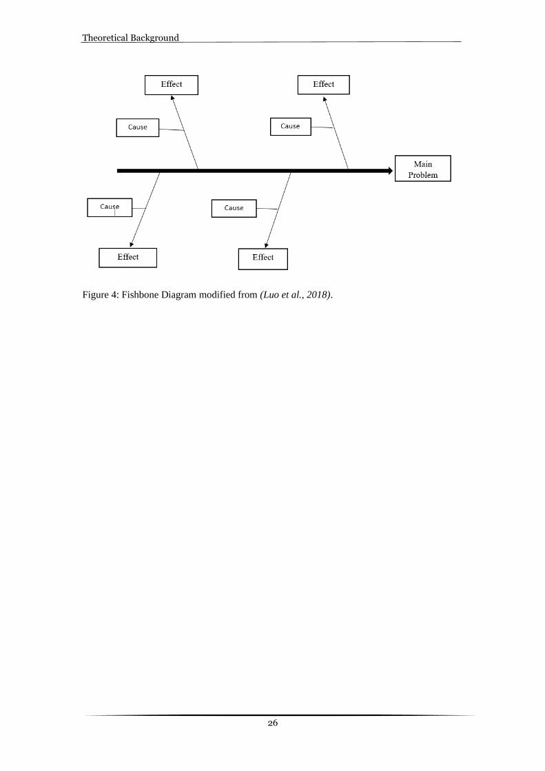
2.6 Fishbone Diagram
Fishbone diagram is also called as cause and effect diagram or Ishikawa diagram. It is
used to represent the effects and factors affecting it. It uses graphical method to link the
causes to the problem (Desai & Johnson, 2013). As there would be many causes for a
particular problem, this tool helps to identify the root cause of a problem in a structured
way. Its name comes from the fact that its analysis depicts a whole barbed fish bone.
As seen in Figure 4, the branches indicate the cause of the problem and the arrows
indicate the effect of problem faced (Luo et al., 2018).
Theoretical Background
26
Figure 4: Fishbone Diagram modified from (Luo et al., 2018).

Methods and Implementation
27
3 Method and Implementation
This chapter will describe the methods that have been considered for the research work.
The chapter will begin with the research design of this chapter, followed by a literature
review conducted to get the data from scientific papers relevant to the topic.
Furthermore, the next section will be about a case study where the authors will speak
about the case and the techniques used to gather all the data. The chapter will end with
the quality of the research, where the validity and reliability of the research will be
outlined.
3.1 Research design
This chapter introduces the reader to the research methodology used to answer the
research questions. At first, literature review and brainstorming are discussed. This
research is mainly based on a qualitative approach. Hence, in the later stages, the
primary data collection methods such as interviews and observations are discussed. The
triangulation method is used to increase the reliability and validity of this report. The
triangulation method is defined as the multiple data collection methods to ensure the
accuracy of the research (Jonsen & Jehn, 2009). It uses multiple methods in the
examination of a single phenomenon. The primary aim is to remove or decrease biases
and increase the reliability and validity of the research. The second objective is to
maximize research legitimacy, thus providing a rich quality resource and a complete
understanding of the studied phenomenon. The third purpose is to increase the trust in
the results of triangulation for researchers (Jonsen & Jehn, 2009).
This research follows both deductive and inductive approaches. The deductive
approach is when a conclusion is drawn from a set of generalized theories. The
inductive approach is when a generalized theory is made from a specific case or an
event (Saunders mark, Lewis Philip, 2016). At the beginning of the report, the deductive
approach develops the theory by reading academic literature. Later, after collecting the
data from the case company, the gathered data is used to generate a generalized method
that all the SMEs can follow.
3.2 Literature Review
All academic research activities are required to base the research on and relate it to
established information. A literature review is a method of gathering and analyzing a
previous systematic study. A successful and well-conducted review establishes a solid
basis for gaining knowledge and supporting theory development as a research tool. A
literature review can address research questions with a strength that no single study can
match by combining results and insights from several empirical studies. Literature
reviews serve as a powerful pillar for all kinds of research. They can serve as a
foundation for knowledge creation, create policy and practice guidance, provide proof
of an outcome, and, if done well, have the potential to generate new ideas and directions
for a field. Sometimes conducting and evaluating a literature review may be

Methods and Implementation
28
challenging, but it will positively support the study if it is conducted systematically
(Snyder, 2019).
A comprehensive and systematic analysis of recent literature is required to resolve key
concerns. Because of the three research questions, both assessment and evaluation of
available literature are included in the study. The literature reviews of these studies
included books, journal articles, conference proceedings, doctoral dissertations, and
reports (Sayers, 2003). The collection method to be used in the research was first carried
out by compiling appropriate articles from publishing sources and the subsequent
removal of non-relevant articles. Paper recovery can be achieved by searching for
keywords and abstract sets from Scopus, ProQuest, Google Scholar, and several more
databases. Articles and textbooks in the series are included in the list. Many filters, such
as year, publication, document form, language, and subjects in the databases, have also
been used successfully, as this approach has helped to minimize the number of papers
to be checked. Some Boolean operators such as AND, OR, “”, *, and NOT are also used
in the literature search. As shown in Table 1 several papers were found which were
reviewed based on relevance to the research questions and research aim. Each paper
was reviewed based on its abstract to gain the gist of the paper and if it matched the
requirements of the research, the paper was further reviewed in detail. Many of the
papers were omitted as they were not entirely relevant to the subject or the work after
going through the abstract. Articles used in reference to the selected paper were also
used for the analysis, as many of them were similar to the subject and had good content
in them (Zachariadis et al., 2013). In Table 1, the results of the thorough literature
review are displayed.
Table 1: The Literature search.
Search Term Database Filters Used Number of hits
Material handling and Lean
Science Direct
Document Type, Publication Date, Subject
113
Systematic Layout Planning
Diva Document Type, Language 11
Layout planning ProQuest Document Type, Language, Publication Date
7
Layout planning and SLP
Science Direct Document Type, Publication Date
5
3.3 Brainstorming
There is a great saying that runs through every researcher’s mind when we talk about
brainstorming, “Genius is one percent inspiration and ninety-nine percent
perspiration”-Thomas Edison. This is a good motto when great ideas are being
generated (Al-Samarraie & Hurmuzan, 2018). Brainstorming can be known as a
method to create new ideas. It is a process where creative ideas are formed to enlighten
our knowledge about the topic we intend to work upon. Brainstorming can either be
done individually or in a group but conducting it in a group can be more effective in

Methods and Implementation
29
finalizing the ideas for our project. Litchfield (2009) describes brainstorming as a
method that helps generate and improve our ideas, rather than looking at it as a task that
often is the case (Litchfield, 2009). Brainstorming consists of certain rules that are to be
followed by individuals as a goal to end up generating the best ideas to progress ahead
(Litchfield, 2009).
1. To produce as many ideas as possible, quantity before quality 2. Allowing all ideas, good and bad. 3. The more original, the better. 4. Using and improving previous ideas is welcomed and encouraged.
During the brainstorming session, the authors of this report made sure to keep the
keywords in mind relevant to the report. It was easier to explore through imagination
and discover all the ideas and solutions required for commencing the project. Though
the ideas generated were broad, it was easier for the group to narrow down the
developed ideas at the earlier stage of brainstorming. Brainstorming as a group always
provides the best and unique ideas than individual brainstorming. While working in a
group, it becomes easier to substantiate the existence of the ideas generated by the group
members. Thus, this report will be using this method throughout the project whenever
necessary. For instance, brainstorming will be a useful tool in findings as well as in
discussion chapters. Therefore, using the brainstorming method would be a great start
in generating specific and feasible ideas to move ahead in the project (Johnson &
D’Lauro, 2018). Furthermore, this method is justified even better when we conduct the
observations we discuss in the following chapter.
3.4 Case study research
The main activity in organizational research is theory development, where the authors
tend to develop a theory based on previous knowledge, experience, and common sense
(Eisenhardt, 1989). Case study research is a method to study and understand the current
setting of the company. A case study can either be done with multiple cases or a single
case. In this thesis project, a single case has been selected to study that specific problem.
A case study depends on data collection techniques such as data analysis,
brainstorming, observations, interviews, document reviews, and literature reviews
(Eisenhardt, 1989). This research method helps in developing some theory or a
hypothesis based on the limited information at the beginning. Case study research is
used to collect qualitative and quantitative data, but here for this thesis, the focus is only
upon collecting qualitative data as the primary data collecting method (Yin & Yin,
2016). Therefore, the main strength of case study research is to gain specific insight
into the problem as the case company. However, there is a drawback to using this
method because it is time-consuming since the collection of data is not as easy as
expected.
The case study research was conducted only in one company: Rehobot Rotex AB. The
case study was conducted based on the data analysis technique and observations done
through video conferencing and digitally pre-recorded videos. This method made it
easier to analyze the material flow and shop floor layout to understand it in a better way
and develop our theory. Furthermore, many other observations were done, leading us
to more detailed problems that the case company is currently facing.

Methods and Implementation
30
Observations
Observation would be useful in this case as it plays an important role in gathering
qualitative data and providing ideas on complementary approaches. Observation can
provide insight and information on material movement and behavior in real-time.
(Liskin, 1979).
This process involves: systematic viewing, capturing, analysis, review, and evaluation
of human behavior and the surroundings. There are four types of approaches: two
traditional methods and two technological methods. The traditional methods need a
participant to physically observe the facility by being there, which is impossible due to
the present COVID-19 situation. This was the main reason to use technological
methods. This method consists of two approaches: The internet-mediated approach and
observation using Videography (Saunders mark, Lewis Philip, 2016).
The internet-mediated approach collects data from online communities such as
company web pages and social networks. This will provide a huge amount of qualitative
data in the form of text and audio-visual material (Hewson & Hewson, 2014).
Videography is the process of recording moving images onto an electronic device.
Mobile phones can also be used to capture digital video in an observational study. This
method provides the researcher with a video recording that can be viewed multiple
times to reflect clearly upon the activities in the workplace and the relationship between
workers. It is very useful in generating a detailed insight into the workplace (Knoblauch
& Schnettler, 2012). This approach is also useful when there is a long distance between
the researcher and the company where face-to-face observation is difficult. This will
help in enhancing the accuracy while collecting the data. A few drawbacks are using
this method like recording a good quality video may be difficult depending on the
workplace, the video may be biased when recording (Saunders mark, Lewis Philip,
2016). This issue is resolved by conducting interviews with the company.
Interview
An interview can be described as a way of gathering data required for conducting
experiments or surveys. While conducting an open-end interview, a semi-structured
interview is best to use where the interviewer can prepare a series of questions. The
interviewer should explain briefly about the study being conducted and accentuate the
person's involvement while maintaining privacy and confidentiality whenever
necessary (Rapley & Rapley, 1994).
A semi-structured interview was conducted with the CEO of the company. A series of
key questions were framed to gain some insight into the data. This was collected from
the observational method, and the questions can be seen in Appendix 1. The interview
with the CEO was conducted on a virtual platform due to the current situation of

Methods and Implementation
31
COVID-19. Though the interview was virtual, it was very beneficial in gathering some
important details required for conducting our studies. The questions can either be in a
systematic order or asked at random, based on how the interview is going, and the
interviews are recorded for future reference. Some unstructured interviews were
conducted as well with the employees, which can be seen in Appendix 2. Unstructured
interviews are informal, and they do not follow any predetermined questions. Rather, a
randomized list of questions was prepared and asked the employees to freely speak
about the problems they might have faced during their work (Saunders mark, Lewis
Philip, 2016).
Table 2: survey questions for employees.

Methods and Implementation
32
Table 3: Survey responses from the employees.
Furthermore, Table 2 represents the set of survey questions that were asked to the
employees. Their responses have been shown well enough in Table 3. Through these
tables, it becomes easier to identify the real problems from another point of view and
helps to focus more on those problems while planning the new layout.
Document Review
Document review is a systematic process in which documents, both written and
electronic content (video or internet-based), are reviewed or assessed. Documents
include text, videos, and photographs that have been collected without the involvement
of a researcher. Documents of all kinds may aid the researcher in analyzing meaning,
gaining knowledge, and uncovering relevant insights into the research problem. As part
of a research project, documents may be used for several purposes (Bowen, 2009).
• Documents may provide information about the environment in which test
subjects work. Such data and insight will assist researchers in gaining a better
understanding of the root cause of certain problems and the factors that
influence the phenomenon currently being studied.
• Documents can suggest some of the questions that should be discussed and
problems examined as part of the study. It will help to generate more interview
questions which in turn gives more data for the research.
• Documents have research evidence that is not found elsewhere. Data derived
from the documents and observations may be a useful addition to the knowledge
base.
• The document will help in tracking the change and development. The researcher
can compare different documents to identify the changes (Bowen, 2009).

Methods and Implementation
33
Document review has many advantages; it is cost and time-efficient than doing own
tests and experiments. The documents are reliable and easily accessible. This will
provide insight and a broad understanding of the current production layout. The
documents will provide information on the current positions of the machines and
include recommendations as to where to reorient the machines. Both digital and
physical records must be reviewed. After a thorough analysis of the relevant data, the
information must be evaluated (Louis Cohen, Lawrence Manion, 2014). The documents
provided by the case company of the current and future facility can be seen in Appendix
3.
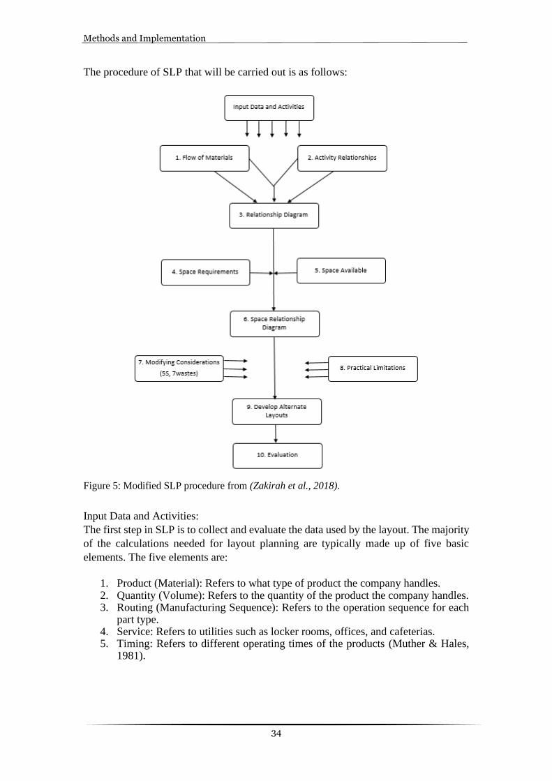
3.5 Systematic Layout Planning (SLP) Procedure
SLP is the method used for planning layout for SMEs. During the literature review, the
SLP method was identified as the best and main method for planning the layout due to
its basic and efficient steps, as shown in Figure 5. Furthermore, this method consists of
different phases and procedural steps for identifying, rating and visualizing the
operations involved in the layout (Muther & Hales, 1981).
A thorough study and research were conducted to gather data such as the flow of
material and operations in the current state layout to carry forward this method. The
information collected will then be useful in understanding the current state and the
future state. It will be easy to develop a deeper understanding of where and how to
create space for the workstations in future layouts, leading to a smooth flow of materials
and a well-organized workplace
Methods and Implementation
34
The procedure of SLP that will be carried out is as follows:
Figure 5: Modified SLP procedure from (Zakirah et al., 2018).
Input Data and Activities:
The first step in SLP is to collect and evaluate the data used by the layout. The majority
of the calculations needed for layout planning are typically made up of five basic
elements. The five elements are:
1. Product (Material): Refers to what type of product the company handles. 2. Quantity (Volume): Refers to the quantity of the product the company handles. 3. Routing (Manufacturing Sequence): Refers to the operation sequence for each
part type. 4. Service: Refers to utilities such as locker rooms, offices, and cafeterias. 5. Timing: Refers to different operating times of the products (Muther & Hales,
1981).

Methods and Implementation
35
Step 1: Flow of Materials
The most important feature of a layout is the material flow. Material handling effort
and costs can be reduced if the sequence and pace of the material movement are
considered when planning the layout. The planner must have a vision of how the layout
should be. After analyzing the material flow and identifying operations relationships,
the planner should combine the two in the form of an activity relationship chart. This
can then be translated into a diagram that explains the arrangement of workstations,
equipment, and material (Muther & Hales, 1981).
Step 2: Activity Relationship Chart
The Activity Relationship Chart assists in identifying the interconnections of all of the
operations and workstations in the layout. Activity relationship analysis provides a
detailed way of connecting the operations and incorporating them into a process. To
analyze the activity relationship, various charts are being used to gather information.
One of the charts is mentioned below (Muther & Hales, 1981).
Table 4: Closeness Relationship Values, modified from (Muther & Hales, 1981).
Value Closeness
A Absolutely Necessary
E Especially Important
I Important
O Ordinary Closeness is Ok
U Unimportant
X Undesirable
Figure 6: Activity Relationship Chart modified from (Muther & Hales, 1981).

Methods and Implementation
36
Figure 6 depicts the activity relationship chart, which will show the importance of the
relationship between different departments. For example, the relationship between the
operator and the supplier is rated as X, which is undesirable because there is no
information flow between them. Table 4 shows the closeness relationship values which
can be assigned in the relationship chart.
Step 3: Activity Relationship Diagram
This process involves developing a visual diagram based on analyzing the gathered data
from the activity relationship chart. With the help of charted information, the visual
diagram can be later modified according to the sequence of activities and the
importance of the proximity to each other. As a result, the diagram can be described as
a basic layout, but it will not be functional until it is updated to accommodate any
changes. Later, the relationship diagram serves as a basis for developing the space
relationship diagram, which is the next step (Muther & Hales, 1981).
Table 5: Closeness Relationship Values modified from (Muther & Hales, 1981).
Value No. of Lines Closeness Rating
A
Absolutely Necessary
E
Especially Important
I
Important
O
Ordinary Closeness is Ok
U
Unimportant
X Undesirable
.
Figure 7: Activity Relationship Diagram modified from (Mikhail & Sadllah, 2020).

Methods and Implementation
37
Figure 7 depicts the Activity Relationship Diagram between different operations or
workstations. For example, the red line represents that the distance between operations
1 and 2 should be very less. The black line represents that the distance between
operations 1 and 5 is unimportant. The representation of each colored line is shown in
Table 5.
Step 4: Space Requirements
Space requirements required for each operation are filled in this step. After charting and
relationship diagram, the next step is to plan the space required for the future facility.
Due to some uncertainties like machinery and equipment, it is difficult to plan the space
requirements for a facility. Five methods are used to determine the space requirements.
Different methods of measuring space requirements tend to cross-reference each other,
giving the diagrams more weight. The five different methods are mentioned below
(Muther & Hales, 1981).
1. Calculation 2. Converting 3. Space Standards 4. Roughed Out Layout 5. Ratio Trend and Projection
Step 5: Space Available
In this step, there will be information about available space, special spatial restrictions,
and other similar factors. When the concern is about the defined space requirements
and the actual space available, the planner must be creative enough to compromise and
balance the operations. This step involves balancing the space requirements with the
available space. If there are some issues in the available space, it is beneficial to
minimize one specific area with the least impact on productivity. This is done by rating
each area based on the importance of the company's operations (Muther & Hales, 1981).
Step 6: Space Relationship Diagram
The results of comparing the space requirement against the space available are
integrated into the space relationship diagram. This acts as a guideline for making
further changes. The space relationship diagram will gradually become a layout after
modifying several factors and their limitations (Muther & Hales, 1981).

Methods and Implementation
38
Figure 8: Space Relationship Diagram modified from (Mikhail & Sadllah, 2020).
Figure 8 represents the space relationship diagram where the dimensions for each
operation are depicted. For example, one operation needs 45 square meters of space on
the layout.
Step 7: Modifying Considerations
This step consists of identifying the potential modifying factors and also the solutions
to these factors. Some of the common modifying factors are the following (Muther &
Hales, 1981).
1. Material Handling methods 2. Lean tools
Step 8: Practical Implications
Practical implications are the restrictions that are imposed while planning a layout. This
includes restrictions like layout planning in an existing building, existing machines,
company policies (Muther & Hales, 1981).
Step 9: Developing Alternate Layouts
The planners should plan and consider the most important or necessary factors to plan
the layouts. The planner can create up to five alternatives. Since it is very time-
consuming and no huge difference between the layouts, two or three alternatives are
enough in most conditions (Muther & Hales, 1981).

Methods and Implementation
39
Figure 9: Alternative Block Layouts modified from (Mikhail & Sadllah, 2020).
Figure 9 shows the alternative block layouts developed while placing the operations in
different ways. For example, in the third alternative the receiving and shipping docks
are placed on either side of the facility. Hence, the first operation (1) and the last
operation (9) are placed on each end of the facility.
Step 10: Evaluation
This step involves evaluating and selecting the most appropriate layout of the developed
alternatives to implement in the new facility. The evaluation procedure is conducted by
the following methods (Muther & Hales, 1981).
1. Balancing the advantages and disadvantages. 2. Factor analysis rating. 3. Cost Comparison and justification.
The major drawback of the SLP technique is that when planning various layout options,
it does not provide detailed instructions on how to manage the material handling
aspects. As a result, the SLP system may be updated or combined with other strategies
for preparing and coordinating material handling aspects to achieve a layout plan that
encompasses all main activities on the shop floor (Pratami et al., 2017).
3.6 Weighted factor analysis (WFA)
WFA is one of the best evaluation methods to come across while planning a layout
using the SLP method. In the WFA method, the goal or objective of planning the layout
will be broken into important factors in planning and achieving the layout. WFA is
conducted by either one or two people who will list all the factors with some definition
of those factors stating their importance. On the other hand, the list of factors stated will
have to be approved by the person responsible for selecting the plan at the final stage
(Muther & Hales, 1981). Since this thesis is conducted in a company, the person
responsible for approving the list of factors would be the company's CEO.
While listing the factors, it is made sure that the list is as clear as possible with a clearly
defined definition of the factors. So that any reader can easily understand what factors
are considered and why they are important (Ning et al., 2018). Avoiding duplication of
factors is a good practice since it will cause serious problems equivalent to the omission
of important factors. Appendix 4 represents the complete list of factors, out of which
only the required factors are selected by the authors and the company required for this
report. Ideally, ten important factors are enough to carry forward the evaluation process

Methods and Implementation
40
(Ning et al., 2018). While rating each plan, it is also recommended to use the SLP vowel
list as shown in Table 7, as it makes it easier to understand and remember.
The procedure that will be used in factor analysis of the alternative layouts are as
follows:
1. Identifying the plans: In this step, the layout plan that is to be evaluated should be selected and distributed among the researchers in the form of a sketch to understand it clearly. To avoid confusion, it is recommended to name the alternate plans as A, B, C…, with a small description about each plan separately (Muther & Hales, 1981).
2. Selection of factors: Here, one needs to establish the list of factors that are wanted or important for that layout with some description of the factors to make the raters understand why that factor was selected first (Muther & Hales, 1981).
3. Adding details in the rating sheet: This step involves listing all the factors selected in the previous step to be included in the rating sheet. In Table 6, all the details are added vertically by leaving some space in the column to make notes in them (Muther & Hales, 1981).
4. Weighing the factors: Once the listed factors are inserted vertically, it is time to weigh all the factors according to their importance relative to other factors listed in the sheet (Muther & Hales, 1981).
5. Rating each factor for each plan: A rating code should be established as shown in Table 7 and then rate all the factors for each layout based on how well it can achieve the requirement. While rating, it is necessary to rate one factor at a time for all the layout plans and enter the rating symbols above the slant line (Muther & Hales, 1981).
6. Calculate the value and total: At first, it will be easier to convert the symbols into numerical values as per Table 7 and multiply each rating value with a weighted value. Once the rating is done, sum all the rated values for all the layouts in their respective column. Finally, based on the result, in the end, appropriate measures should be taken (Muther & Hales, 1981).

Methods and Implementation
41
Table 6: Weighted factor analysis method of evaluation modified from (Muther & Hales, 1981)
Table 7: Rating Code and Values modified from (Muther & Hales, 1981)
Value Closeness Numerical Value
A Absolutely Necessary 5
E Especially Important 4
I Important 3
O Ordinary Important 2
U Unimportant 1
X Undesirable 0

Methods and Implementation
42
3.7 Research quality
To ensure the high quality of the research and its results, continuous quality checks of
the collected data are essential (Heale & Twycross, 2015). Therefore, different data
collection methods are used to avoid or minimize the effect of biased data (Jonsen &
Jehn, 2009). This research requires reliability and validity tests to ensure its
trustworthiness and quality. Reliability implies replication and consistency, and if a
researcher can repeat an earlier research design and come up with the same results, the
research is considered reliable. Validity refers to the accuracy of the measure, the
accuracy of result analysis, and the generalizability of the findings (Saunders mark,
Lewis Philip, 2016).
Reliability
According to Hammersley (1987), reliability is the degree to which the same results
are obtained when the study’s methods are repeated (Hammersley, 1987). If the
reliability requirements are not met, the researcher may obtain inaccurate results,
making reliability an essential factor (Heale & Twycross, 2015). The study's
reliability is improved by explaining and clarifying how it will be carried out (Potter
& Levine-Donnerstein, 1999). In this thesis, the reliability was assured by
thoroughly explaining the research methodology procedure in chapter three. By
doing so, the researcher can be sure that if the method described in Chapter three is
followed exactly, the same results can be achieved in another study. To achieve high
reliability in this thesis, different data collection methods are used, such as
interviews, document reviews, observation, and video recording. In this thesis, a
large number (60%) of the employees in different positions and different areas were
interviewed. On the other hand, the information obtained from the literature review
was systematically and thoroughly evaluated.
Validity
When it comes to validity, it can be categorized into two types: Internal validity and
external validity. Internal validity is the measure of what is intended to be measured.
External validity means that the results could be generalized and apply to other
companies (Saunders mark, Lewis Philip, 2016). According to Potter (1999),
observations made during a study can be influenced by the researcher's
preconceived notions. Jonsen (2009) states that the triangulation method is a
strategy used to increase the validity (Jonsen & Jehn, 2009). Therefore, during this
thesis work, the triangulation method, which implies using more than two data
collection methods, was used to avoid this issue. Internal validity is improved by
taking measures such as carefully going through the video recordings and the
gathered data many times. This study's generalizability extends to companies that
operate in similar environments.

Methods and Implementation
43
Ethics and morale
Ethics includes right- behavior ideals and ideas. Ethics or morality have been
identified as the sole comprehensible foundation for morality or ethics would be to
do no action that clearly or purposefully damages other persons. Therefore, ethics
is the concept that encloses many rules and principles for the right conduct of
research (Sanjay Singh, 2012). There are several principles in ethics that are to be
followed, but Christensen (2015) has disintegrated the principles into few core
principles that can make more sense to the research work,
• There should be transparency of the research work between all the participants.
• Participants have the power to decide whether they want to get involved or not
in the research work.
• The participants involved in the research must agree to all the terms of
confidentiality since many involved in the research can be sensitive data that
cannot be shared with others directly.
• Lastly, the data gathered through interviews and observations can only be added
to the research and avoid adding any private information (Christensen, 2015).
These principles were followed thoroughly throughout this report, whether it was
an interview or any observations during the video conferencing. The authors of this
report have made sure to fulfill all the requirements while being transparent to all
the participants involved.

Findings
44
4 Findings This chapter contains all the data collected on the different aspects of the existing production system. It also provides the analysis of the current production based on the theories presented in the Theoretical background. Connections between the theory and analysis will be built, and alternate layout plans will be analyzed to answer the research questions in this chapter.
4.1 Current State
Before moving forward with the planning of the future facility, the study will perform
a current state analysis of the manufacturing plant. This is done to gain a better
understanding of the processes and material flow that will be essential in the future
facility. Furthermore, the researchers can classify waste that can be removed inside the
future facility by performing a current state study.
Unlike the current manufacturing plant that operates on an area corresponding to only
1500 square meters, the future facility will operate on an area involving 3000 square
meters. To create an effective layout consisted of coordinated workflows, the planning
process for the future plant will be focused on aspects such as material handling
effectiveness, storage effectiveness, safety, and flow of materials.
4.1.1 Layout description
The existing production facility to be studied is situated in Partille and covers an
area of 1500 square meters. A major part of the facility consists of 47 turning
machines, 43 of which are smaller Rotex turning machines compared to the other 4
CNC turning machines. The other parts of the facility include departments such as
receiving area, storage, office rooms, and packaging area, to name a few. The total
number of machines in the current facility is 53, including a shaker, washing
machine, centrifuge, and a few more. It also contains material handling equipment
like an overhead crane and a forklift truck. The layout of the facility is shown in
Figure 10, and the position of the different operations of the facility is highlighted.
Lines have been drawn over the area that is not relevant to the research.
The case company produces precision parts in high volume, which is of few
different varieties. For this type of production, the case company has used a product
type layout where mass production becomes easy. Since the company is producing
only one type of product, it was evident that the product type layout suits the most.
In this type of layout, the machines have to be kept in a sequence of the process so
that there is a smooth flow of material. Product type layout has been implemented
for another reason that is because of the flexibility which it provides. By flexibility,
it means that the layout can be altered at any given point in time depending on the
demand or type of change required. Though the machines are kept in a sequence of
operations which makes the material flow easier, the current layout has not followed
a systematic placement of machines to justify the product type layout. As shown in
Figure 10, the structure of the building is in such a way that the layout is divided into

Findings
45
two sections. In one section (left side), most of the operations are done while only
turning operation is performed in the other section (right side). Due to this, the
placement of machines has not been done efficiently.
Figure 10: Current production layout
4.1.2 Current Operations
The information about current operations was obtained after a thorough study of
documents, video recordings, and interviews conducted with the company. The
following are the step-by-step operations that take place in the manufacturing plant's
studied area, as shown in Figure 11.

Findings
46
Figure 11: Current operations
• Raw Material Storage (1):
This is where the raw material is received from the basement and stored on the shop
floor. The raw materials come in two sizes, that is, in 3 meters and 600-millimeter
length rods. Most of the raw materials come in 3 meters in length. The rods are made
up of different materials such as Steel, Brass, Stainless steel, and Aluminum. To provide
a buffer, some of the rods are placed near the turning machines.
• Cutting (2):
The cutting machine is used in this operation which is placed next to the raw material
storage. So, this helps in loading and unloading the machine. The 3-meter rods are cut
into 600-millimeter rods to feed it into the Rotex turning machines in this operation.
This operation takes place in a cutting machine of size 3.37 square meters.
• Machining Process (3,4):
This process involves only turning operations. This operation is performed in two types
of machines – Rotex turning machines (4) which are smaller, and CNC turning
machines (3) that are comparatively bigger. These machines perform only tuning
operations. The rods are turned into small precision parts with a diameter of 2 – 16
millimeters. The CNC turning machines are fed with 3 meters rod as raw material, while
the Rotex turning machines are fed with the 600-millimeter rod as raw material. The
machines use oil as a coolant. Finally, the finished product is collected in a container.
• Centrifuge (5):
The finished products contain excess oil. So, the finished products will undergo a
centrifuge process. The excess oil will be removed and collected in a separate oil
container, which can then be reused in the machines.

Findings
47
• Deburring (7):
After removing the excess oil from the finished products, they are put in the shaker to
remove the burrs.
• Washing (8):
There are three washing machines. Two machines are used to wash the steel products,
and the third machine is used to wash brass, stainless steel, and aluminum products.
The finished products are washed in one of the machines depending on the raw material
used.
• Packaging (9):
After the finished products are thoroughly washed, the quality of the products is
checked. Then they will be packed in carton boxes.
• Finished Product Storage (10):
The packed parts are stored on the shelf or in a pallet according to the order from the
customer. Finally, they are sent away from the storage to the customers.
4.1.3 Evaluation of Current Facility
To detect existing waste that could be removed during the review, interviews were performed with the company's CEO. Via interviews and documentation study of the shop floor, authors tried to recognize challenges and possible bottlenecks. Table 8 represents the factor analysis of the current layout where all the factors that are important in the current layout are listed, and the current layout is evaluated based on those factors. Table 9 represents the rating codes and their values. This method follows the listing of factors considered important in evaluating the layout after discussing it with the company contact person. Further, the listed factors are weighted according to their importance compared to the other factors. Each factor is rated after a discussion between the authors and the company contact person. Then the rated value of each factor is multiplied with the weighted value. Finally, all the rated values are summed to get the total score. This score will be used to compare with the score of the future layout.
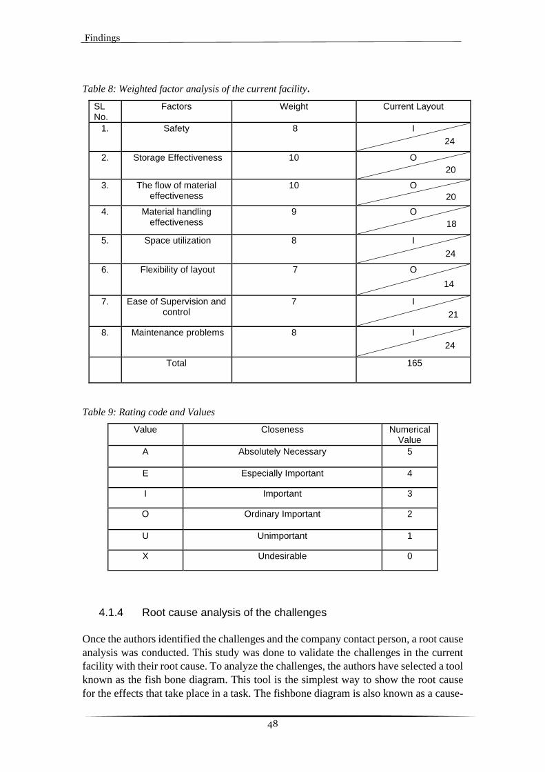
Findings
48
Table 8: Weighted factor analysis of the current facility.
SL No.
Factors Weight Current Layout
1. Safety 8 I
2. Storage Effectiveness 10 O
3. The flow of material effectiveness
10 O
4. Material handling effectiveness
9 O
5. Space utilization 8 I
6. Flexibility of layout 7 O
7. Ease of Supervision and control
7 I
8. Maintenance problems 8 I
Total 165
Table 9: Rating code and Values
Value Closeness Numerical Value
A Absolutely Necessary 5
E Especially Important 4
I Important 3
O Ordinary Important 2
U Unimportant 1
X Undesirable 0
4.1.4 Root cause analysis of the challenges
Once the authors identified the challenges and the company contact person, a root cause
analysis was conducted. This study was done to validate the challenges in the current
facility with their root cause. To analyze the challenges, the authors have selected a tool
known as the fish bone diagram. This tool is the simplest way to show the root cause
for the effects that take place in a task. The fishbone diagram is also known as a cause-
24
20
20
18
24
14
21
24
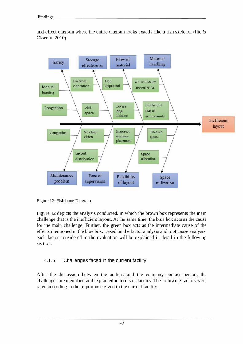
Findings
49
and-effect diagram where the entire diagram looks exactly like a fish skeleton (Ilie &
Ciocoiu, 2010).
Figure 12: Fish bone Diagram.
Figure 12 depicts the analysis conducted, in which the brown box represents the main
challenge that is the inefficient layout. At the same time, the blue box acts as the cause
for the main challenge. Further, the green box acts as the intermediate cause of the
effects mentioned in the blue box. Based on the factor analysis and root cause analysis,
each factor considered in the evaluation will be explained in detail in the following
section.
4.1.5 Challenges faced in the current facility
After the discussion between the authors and the company contact person, the
challenges are identified and explained in terms of factors. The following factors were
rated according to the importance given in the current facility.

Findings
50
1. Safety:
The safety of the current facility is rated 3, which is considered Important (I). The
current facility is more congested as the machines are placed close to each other,
and because of this, the degree of freedom is less. The heavy raw materials are
loaded manually into the machines, which may lead to workplace injuries.
2. Storage Effectiveness:
The storage effectiveness is rated 2, which is of Ordinary Importance (O) in the
current facility. This is because the accessibility of raw materials is not very
convenient. The space for storage of raw materials is also less as the materials have
to be replenished by restocking them regularly. It is also difficult to store the raw
materials near the machines, so the staff should restock the machines by traveling
between the storage area and machines.
3. The flow of material effectiveness:
The flow pattern of the material is not consistent in the current facility as the
operations are not in sequential order. In the current facility, the operation sequence
is not very effective; the materials have to cover more distance to complete the
process. This was rated 2 (O) because of the ineffective flow of materials on the
shop floor.
4. Material handling effectiveness:
The current facility uses overhead cranes to move the raw materials from the
receiving area to the storage area. The material handling equipment is not used
efficiently as the staff must load the heavy raw material in the CNC turning
machines manually, leading to physical stress. Damage of materials while loading
leads to low quality of the final product. There is a lot of unnecessary movement of
material on the shop floor. This factor was also rated 2 (O) because of the ineffective
material handling system.
5. Space Utilization:
The space in the current facility is not effectively utilized. The space on the shop
floor is very congested to move around. The movement of raw materials from the
storage to machines takes more time as the space between the machines is very
little. The space provided for the storage of raw materials is also less, because of
this logistic problem is faced. The materials are brought from the basement to
restock it. There is not enough space for storing raw materials near the machines.
This was rated 3 (I) as it shows an ineffective use of space in the current facility.
6. The flexibility of layout:
Since the beginning, there has been a practice of old methods that have led the
company to have a simple production layout plan which is not flexible enough;
hence it was rated 2 (I). Thus, the allocation of space for each machine and office
has not been done appropriately. This makes the current facility nonflexible, and
therefore, there is a need to improve this layout to make it more flexible.

Findings
51
7. Ease of Supervision:
Though the layout is distributed well, yet was not balanced properly. It becomes a
difficult task to supervise and have visibility of the entire area simultaneously as all
the machines are not placed systematically. But it was easier to reassign employees
to other work as few employees are working, and thus due to this reason, this factor
was rated 3 (O).
8. Maintenance problems:
In the current facility, maintenance of the facility has been done well on a day-to-
day basis, but the space available to perform these services is not sufficient. By
maintenance problems, it means machine service and having enough space to
perform maintenance activities that let the employees repair the machines
conveniently. Therefore, this factor was rated 3(O).
4.2 Parameters of the Future facility
The case company has been working on their project in a well-distributed layout, and
they utilize all the machines available on the shop floor. There are few extra machines
that the case company has placed in a different location and will use all of those
machines in the new facility. This has created a challenging task for the company to
handle the project and focus on increasing productivity simultaneously. Therefore, the
case company has decided to relocate to a new facility where all the production work
will be done on the same shop floor. But there have been some uncertainties with the
future facility’s criteria and parameters. For instance, in the future facility, placement
of extra machines has not been established. These uncertainties hinder the decision-
making process for the authors regarding the future facility. The authors of this report
were given full freedom to plan the production flow of the future facility according to
their ideas. Figure 13 shows the layout of the future facility. Furthermore, the case
company provided information about the new facility such as offices, departments, and
coffee rooms. These include the following: • Dimension of the Future Layout: Total area of 3000 square meters. • Departments and Workstations: Loading/Unloading area, Storage area,
Machining area, Packaging, Maintenance workshop. • Estimated Personnel: 10 employees. • Estimated number of machines: 72 machines. • Material Handling Equipment: Overhead Crane and Forklift Truck. • Offices and Coffee room • Maintenance workshop and changing rooms. • Factors to consider: Safety, Storage Effectiveness, Flow of material
effectiveness, Material handling effectiveness, Space utilization, Flexibility of layout, Ease of Supervision and control, and Maintenance problems.

Findings
52
Figure 13: Future Facility
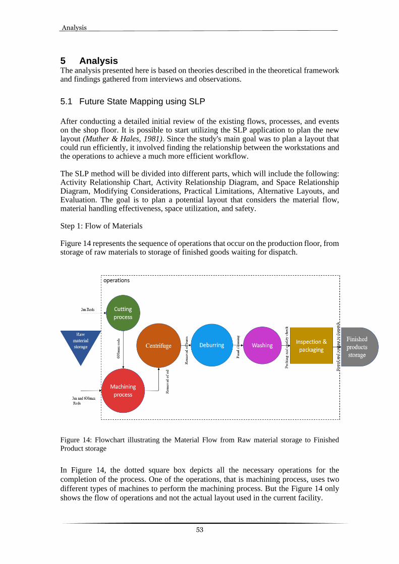
Analysis
53
5 Analysis The analysis presented here is based on theories described in the theoretical framework and findings gathered from interviews and observations.
5.1 Future State Mapping using SLP
After conducting a detailed initial review of the existing flows, processes, and events on the shop floor. It is possible to start utilizing the SLP application to plan the new layout (Muther & Hales, 1981). Since the study's main goal was to plan a layout that could run efficiently, it involved finding the relationship between the workstations and the operations to achieve a much more efficient workflow. The SLP method will be divided into different parts, which will include the following: Activity Relationship Chart, Activity Relationship Diagram, and Space Relationship Diagram, Modifying Considerations, Practical Limitations, Alternative Layouts, and Evaluation. The goal is to plan a potential layout that considers the material flow, material handling effectiveness, space utilization, and safety. Step 1: Flow of Materials Figure 14 represents the sequence of operations that occur on the production floor, from storage of raw materials to storage of finished goods waiting for dispatch.
Figure 14: Flowchart illustrating the Material Flow from Raw material storage to Finished
Product storage
In Figure 14, the dotted square box depicts all the necessary operations for the
completion of the process. One of the operations, that is machining process, uses two
different types of machines to perform the machining process. But the Figure 14 only
shows the flow of operations and not the actual layout used in the current facility.

Analysis
54
Since the company's beginning, they have been into mass production, and the best
suitable layout for mass production is product type layout. Though the layout worked
well initially, it could not sustain for a longer time as the placement of machines was
not done appropriately. Hence, it clears the path for the authors to plan the future layout
in the new facility by choosing the best layout type that can withstand any change in
the future. Therefore, after a thorough study, the authors have found that product layout
should be implemented in the future layout with correct placement of machines. This
way in the new facility it will become easier for the movement of material from one
operation to another and a lot of working time can be saved. Step 2: Activity Relationship Chart Upon constructing a flowchart depicting the operations that occur on the shop floor, it represents how the material flow is in its current state. This depiction will help develop an Activity Relationship Chart and evaluate the relationship between the various operations and workstations (Muther & Hales, 1981).
Figure 15: Future Activity Relationship Chart between the operations.
An activity relationship chart is created to gain a deeper understanding of the activities that take place and their relationships in the current state. Figure 15 depicts the Activity Relationship Chart of the current state, which includes the relationship between various operations. This chart will explain how close the operations need to be to each other in

Analysis
55
the future state. The grades were assigned based on the operations depicted in the flowchart within the current facility. Once the Activity Relationship Chart is constructed, the most important relationships can be identified. For example, one of the most important relationships is the distance between the machining process and the centrifuge. This is because once the parts come out of the machines, it contains oil which is used as a coolant in the machining process. Hence, the oil must be removed with the help of a centrifuge to move to the next step of the process. Therefore, the distance between the machining process and the centrifuge must be as short as possible. This will help in saving time and reducing the traveling distance between these two areas. An example of one of the least important relationships is the distance between the cutting process and packaging. This is because there is no direct material flow between these two operations, as the products cannot be packed before it undergoes the remaining operations. After constructing the Activity Relationship Chart, the data in the chart will help in analyzing Activity Relationship Diagram. As explained in the Methods chapter, the Activity Relationship Chart is constructed to depict the Activity Relationship Chart’s results geographically. Hence, this will give an idea of how the future layout is planned. Step 3: Activity Relationship Diagram In this step, the objective is to present the charted data in a geographical form to identify the best possible locations for the listed operations (Muther & Hales, 1981). This can be accomplished by focusing on minimizing the number of overlapping lines. This will reduce the traffic and accidents caused in the future production layout. It is essential to define and draw the most important connections between stations when starting an Activity Relationship Diagram, as this relationship will help form the future layout. Therefore, the least important relationships between the operations can be placed at last.
Figure 16: Future Activity Relationship Diagram
Analysis
56
Each circle within the Figure 16 represents an operation on the shop floor. Each circle is connected to at least one other circle, as shown in the above Figure. But the importance of the relationships between the operations is defined by the way the lines are drawn. The circle’s location is determined by its relationship to the flow of material on the shop floor. However, overlapping lines should be minimized. Unfortunately, it sometimes occurs that the future layout has the same area for storage of raw materials and finished products. The lines have been color-coded to represent the importance of the relationship between the operations. The Activity Relationship Diagram explains clearly why the closeness between various operations is so important. This, in turn, will help in planning a future operational layout. Therefore, one can reduce the unnecessary distances, movement, and workflow overlap by using the Activity Relationship Diagram to position stations. Step 4: Space Relationship Diagram After arranging the operations in geographic order, the next step is to establish space for each activity. Then the area is allotted to respective operations in Activity Relationship Diagram to form Space Relationship Diagram. This can be done by determining the space required and balancing it with the space available (Muther & Hales, 1981). Since the production layout and additional machines are shifting to a larger facility, it is important to estimate future space requirements to be modified to fit in the actual space available. Today's operations are carried out on an area of 1500 square meters. The future facility is 3000 square meters. Hence, it is important to manage the space requirements to be balanced within the actual space available to develop an operational layout from the Activity Relationship Diagram. The main difference between the Activity Relationship Diagram and Space Relationship Diagram is the addition of space requirements within the Activity Relationship Diagram. As this report adopts to present a plan with a general overall layout and because the researchers cannot be physically present in the facility, it is suitable to select the Roughed-out Layout method of space determination.

Analysis
57
Figure 17: Future Space Relationship Diagram
When considering the various space requirements for each station, it is also important to allow sufficient space for personnel to move between stations. This is particularly important among the aisles near the storage area where the forklift trucks can travel freely. The future layout estimations are done based on the current space requirements and the information and data provided by the company. After considering all the information present, the estimated data of each operation in the future layout is represented in Figure 17. The dimension of each operation in the figure is provided by adding the dimensions of all the machines in that operation. To provide sufficient space between the machines, two times the dimension of each machine is considered when calculating the total dimension requirement of each operation. These calculations were done roughly to provide approximate space requirements. For example, in Figure 17, the 5th operation is the Deburring operation, in which the dimension of the machine is 1.5 square meters. While the dimension given for this operation is 3 square meters to have enough space around the machine. After determining the rough space requirements for each operation and balancing them against the available space, the measurements are applied to the Space Relationship Diagram. Dimensions of each machine are presented in Appendix 5. As a specific location of the plant has already been decided by the company, the Space Relationship Diagram was made according to the floor plans. In the above Space Relationship Diagram, the relationship lines have been color-coded according to their importance. The Red lines are represented as necessary, whereas the Black lines are represented as Unimportant. The raw material storage area requires more space as there is only one storage area on the shop floor, unlike the current facility with a main storage area in the basement. The Machining process takes the second most amount of area as it contains more turning machines which are huge to be placed in the layout. In the future, these values may vary depending on future production needs and staff required for the future facility.
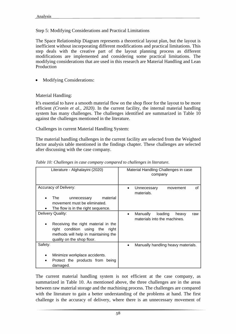
Analysis
58
Step 5: Modifying Considerations and Practical Limitations The Space Relationship Diagram represents a theoretical layout plan, but the layout is inefficient without incorporating different modifications and practical limitations. This step deals with the creative part of the layout planning process as different modifications are implemented and considering some practical limitations. The modifying considerations that are used in this research are Material Handling and Lean Production
• Modifying Considerations:
Material Handling:
It's essential to have a smooth material flow on the shop floor for the layout to be more efficient (Cronin et al., 2020). In the current facility, the internal material handling system has many challenges. The challenges identified are summarized in Table 10 against the challenges mentioned in the literature. Challenges in current Material Handling System: The material handling challenges in the current facility are selected from the Weighted factor analysis table mentioned in the findings chapter. These challenges are selected after discussing with the case company.
Table 10: Challenges in case company compared to challenges in literature.
Literature - Alghalayini (2020) Material Handling Challenges in case company
Accuracy of Delivery:
• The unnecessary material
movement must be eliminated.
• The flow is in the right sequence.
• Unnecessary movement of
materials.
Delivery Quality:
• Receiving the right material in the
right condition using the right
methods will help in maintaining the
quality on the shop floor.
• Manually loading heavy raw
materials into the machines.
Safety:
• Minimize workplace accidents.
• Protect the products from being
damaged.
• Manually handling heavy materials.
The current material handling system is not efficient at the case company, as
summarized in Table 10. As mentioned above, the three challenges are in the areas
between raw material storage and the machining process. The challenges are compared
with the literature to gain a better understanding of the problems at hand. The first
challenge is the accuracy of delivery, where there is an unnecessary movement of

Analysis
59
materials on the shop floor. This is because the machines are not placed in sequential
order. All the machines used for turning operation are not placed in the same area, so
the materials cover more distance to go to the next operation in the process.
The second challenge is the delivery quality, where the raw materials are not efficiently
loaded into the CNC turning machines. The raw material required for the CNC turning
machines is heavy, and this material handling is done manually. Dropping the raw
materials leads to faulty final products. The third challenge is safety. Due to the manual
handling of heavy materials, there are chances of workplace accidents. This is because
the overhead crane is not used efficiently to load the CNC turning machines when
needed. Most of the above material handling challenges are faced due to less space
available within the current facility. Because of this, enough material cannot be stored
near the operations, resulting in inefficient material storage and movement.
Improvement of Material Handling System:
According to Ray and Sidharatha (2019), the material handling system can be improved
by following few basic principles. These instructions can be used to solve material
handling problems (Ray & Sidharatha, 2019). The concepts are carefully understood,
and only the required principles are applied to the challenges. The challenges identified
are summarized in Table 11 against the principles mentioned in the literature. The
Delivery Quality and Safety problem is formed due to the same challenge. So, both
these challenges are combined to avoid confusion.
Table 11: Challenges in case company compared to improvements in literature.
Material Handling Challenges in case company
Literature - Ray and Sidharatha (2019)
• Unnecessary movement of
materials.
• Material Flow Principle
• Simplification Principle
• Space Utilization Principle
• Manually handling heavy materials.
• Mechanization Principle
• Dead Weight Principle
• Maintenance Principle
• Safety Principle
The challenges are compared against the literature in Table 11 to better understand the
principles implemented to improve the material handling system in the future facility.
1. Unnecessary movement of materials. • Material Flow Principle: The operations should be arranged sequentially to
reduce unnecessary materials on the shop floor. The related work areas should be close to each other. Material movement should be in a direct path so the backtracking and zig-zag movement can be avoided. The machining process that uses heavy raw materials is placed closer to the storage area.

Analysis
60
• Simplification Principle: The operations are placed close to each other to
reduce the movement. The workers are given proper training to deliver the
materials to the correct location the first time. Place the raw materials in the
original container near the machines. Avoid using different equipment types
and sizes.
• Space Utilization Principle: Use the facility area in the best way. Keep the
related operation close together. Use building height to stack the raw
materials. Make use of racks or shelves while stacking the finished products.
Clean the storage area and dispose of the scrap regularly.
2. Manually handling heavy materials. • Mechanization Principle: Use material handling equipment when needed. This
is done when the materials are heavy to be moved and loaded into the machines manually.
• Dead Weight Principle: Avoid unnecessary movement of the equipment. Use equipment with lightweight material for material handling like collecting and storing the finished products.
• Maintenance Principle: To avoid interruptions, plan maintenance and repair work on all material handling equipment. Train the personnel properly to do the repairs. The condition of the equipment should be checked and reported daily. Standardize the equipment used on the shop floor. Avoid overloading of material handling equipment.
• Safety Principle: The material handling methods and equipment must be safely
handled. Do not overload the equipment. Provide good lighting on the shop floor. Ensure the environment is clean. Train the material handling equipment operators properly. Stack and unstack the materials in a safe manner. Avoid using defective equipment.
Lean production:
At first glimpse, the Lean theory improvement methods seem to solve several kinds of production-related problems in the SME. Lean can either help avoid the SME's failure or make the existing process world-class (Ortiz, 2015). It is important to review the layout plan to find waste that must be removed in the future plan. Discover the areas of improvement that can be incorporated to generate leaner operations before planning a new layout from scratch (Zhou, 2016) While conducting the current state analysis, lean manufacturing tools have played a vital role in identifying Non-Value Added (NVA), Necessary but Non-Value Added (NNVA), and Value-Added (VA) waste (Ortiz, 2015). Lean tools not only help in identifying waste but also helped in discovering the real problems in the current facility, which need to be improved in the new plan for the new facility. Once the waste or nonvalue added activities had been identified, it becomes easier for the researchers to plan and execute their work towards implementing improvements in the areas where the errors occur. Waste in the manufacturing process is inevitable since to make a component many processes are involved, eventually waste also exists.

Analysis
61
Identification of waste: • Transportation:
On a production floor, the movement of materials can be classified as NVA, NNVA, and VA. The first and last movement of material is NNVA if the distance traveled is more than expected (Bayo-Moriones et al., 2010). In reality, the movement of materials between the storage and the operations is a must. While the real problem occurs when the material is moved many times, this type of movement is classified as NVA. In the current facility, the operations are distributed so that it becomes harder to move raw material to the machines. There is alternative storage in the basement, which is used when there is no place to keep the raw materials in the actual place. This also becomes a problem to get material from the basement to the shopfloor. Thus, transportation of material from storage to shopfloor needs to be rectified in the new facility by allocating enough space for storage on the shop floor and having buffer systems close to the machines (Bayo-Moriones et al., 2010).
• Unnecessary motion:
Materials are being moved many times in the current shop floor, which consumes much valuable time; thus, proper material handling is necessary. This waste is classified as NNVA since the movement is necessary but does not add value to the customer (Chee Houa et al., 2018). In the current facility, most of the movement of materials is done manually, which disrupts productivity as it may take more time as well as causing injuries to the workers. There are forklifts on the shop floor, but they do not match the number of forklifts required on the shop floor. Due to this shortage of forklifts, there is unnecessary movement of materials.
• Waiting:
As mentioned in the previous waste, there is a shortage of forklifts which causes waiting of machines or materials to be transported from one machine to another or from storage to the production floor. Therefore, this waste is classified as NVA since it wastes a huge amount of time due to the shortage of forklifts (Chee Houa et al., 2018)(Bayo-Moriones et al., 2010).
• Human creativity:
A huge amount of time is utilized in moving and handling the materials by the workers. There is no need to have creative thinking to lift the material and move it to its place. However, the operators can use their creative minds to improve the way of moving the materials and how not to focus on NVA and NNVA instead focus on VA (Chee Houa et al., 2018).
These wastes mentioned above need to be rectified to make the production flow efficient and productive enough. Some of the best tools used to resolve the waste are 5S and visual management, which will also help improve the future layout plan. 5S: The primary objective of a lean method is to generate efficient, quality products that can deliver finished goods. The management should build an atmosphere using the 5S approach, where the quality of work is convenient, tidy, and secure. 5S is a waste reduction framework that optimizes efficiency and consistency by ensuring a proper working environment and using visual indicators to obtain more reliable operating results. Fortunately, the commitment and involvement of executives is a crucial element in the effectiveness of the 5S practice. Furthermore, it is insufficient interaction between

Analysis
62
management and shop floor staff that has become the main obstacle to the introduction of 5S successfully and bad training about 5S knowledge. The 5S pillars are: • Sort (Seiri ): It involves recognizing the necessary and unnecessary objects of all
resources, equipment, machinery and retaining the important elements in the workplace. Since the company is relocating to a new facility, it becomes easier to implement from the beginning by systematically placing all the required items close to the machines. Currently, many items have not been placed correctly in the present facility, especially the raw material storage, where everything is kept at random. This type of error should not be followed in the new facility; thus, sorting must be implemented in the new facility plan right from the beginning. It is a good practice to incorporate a system to identify using red tags. In this system, all the things needed are listed and then breakdown into three categories. 1. Garbage and junk. 2. Unneeded, never to return. 3. Low use items.
All the listed items are separated into three categories and given red tags depending on which category they belong to. Therefore, red-tagging the items will help in organizing everything systematically, helps keep track of everything, and finally indicates what needs to be removed. By using this system in the new facility, there can always be a system set to keep all the necessary things (Ortiz, 2015). • Set in order (Seiton): This step deals with setting everything in order, which helps
and makes it easier to find whenever needed. This is the second step after the sorting process. Most of the work is done in this step, mainly focusing on keeping all the stuff in place. It is basically at this point where aisleways, machines, and tools are given locations. This step will be an advantage in planning the new layout, giving enough space to carry out all the activities on the shop floor (Bayo-Moriones et al., 2010).
• Shine (Seiso): This step deals with cleaning, maintaining, and keeping the
workstations clean. These activities are done not just after the work shift but also during the shift whenever the workers notice anything untidy around them. This step is all about keeping everything clean so that hygiene is maintained and keep the machine clean to improve its durability (Bayo-Moriones et al., 2010).
• Standardize (Seiketsu): This step is to create a standardized way of working to keep
workflow and get everyone involved in practicing the standard way of working. By following this step, the case company can continue to identify and sustain its future improvements. Standardization not only makes the process systematic but also improves safety as well. To implement this step, the case company will have to use color-coding to differentiate between the operations. This type of standardization will help in training new employees in an easier way (Ortiz, 2015).
• Sustain (Shitsuke): Sustain or also known for discipline that every worker and
manager must abide by while working on the shop floor. The top management must make sure that all the procedures are clearly explained and displayed if necessary (Ortiz, 2015).

Analysis
63
Visual management: Visual management is the tool that should be used in every industry to visualize information that can help in understanding the direction clearly. Visual management can be used in two ways, firstly as an information tool where it provides only information in a flowchart. Secondly, it can be used as a directive tool where both information and direction are included in the chart where the workers can know what is needed to be done. There are three main flows that every industry experiences: the flow of material, information, and cash. Visual management is one of the best tools used to handle the flow of information on the shop floor at a very low cost (Eaidgah Torghabehi et al., 2016). Improvements that can be done using visual management:
• Simple information flow: It is a best practice to place simple information about material flow in the flow chart form on the shop floor.
• Information at the point of use: Instructions on using tools and equipment should be provided on the shop floor.
• Empowers employees: Information regarding lean should be displayed on the shop floor, which leads the workers to gain knowledge and implement it in their work.
• Improves communication and feedback: There will be better communication between the workers by displaying proper instruction and information regarding the operations.
• Increased transparency: There should be meetings conducted where both the management and the workers are involved, keeping transparency in the workplace.
• Disciplined workplace: A set of standardized rules should be put forth that everyone should follow to have a good working culture (Kurpjuweit et al., 2019).
These modification must be incorporated in the planned layout to an efficient
workplace.
• Practical Limitations: The restrictions imposed on the planning stage layout are called Practical limitations
(Muther & Hales, 1981). After discussing all the modifying considerations, the
practical limitations result in additional charges in the layout planning. The limitations
that are present in the future facility are:
• The layout is built in an existing facility.
• The receiving and the shipping areas are already decided.
• The number of employees is fixed.
• The sequence of flow is predetermined.
• The coffee room and the offices are on the second floor of the facility. • Area for changing room and maintenance workshop is mentioned but not
considered in the material flow.

Analysis
64
Step 6: Alternate Layouts According to Muther and Hales (1981), all the important and necessary factors are
considered to plan the alternatives for the future layout (Muther & Hales, 1981). After
conducting layout planning charts and diagrams, the actual layout plan could be
initiated. Using SLP as a tool for planning the layout, it is important to develop
alternative block layouts that can be compared and evaluated to select the best
alternative. The alternative block layouts will later be drawn using 2D software to
provide a better picture to be easily explained to the management at REHOBOT Rotex
AB. Since planning the future layout was the main purpose of the study, three alternative
layouts are developed. Each alternative layout was developed by considering factors
such as space utilization, storage effectiveness, material flow, materials handling, and
safety. The planning process began with a drawing of the available space to fully
understand how wide the future area will be. After the boundaries have been defined,
the different operations are positioned according to the activity relationship chart and
diagram. According to Muther and Hales (1981), the material flow within the layout is a critical factor in determining a facility's overall productivity (Muther & Hales, 1981). Due to the flow of materials having a huge impact, it is important to place the operations sequentially. As mentioned above in the practical limitations, the entry and exit points of the facility have already been decided. So, the layout is planned according to that limitation. Detailed placement of the equipment and machines are not shown in the alternatives as this study is based on planning a general overall layout. Furthermore, all the alternatives planned are based on using one combined dock, which means that the inbound of raw materials and outbound of finished products will be done at the same dock. This is because of the practical limitation put forth by the company, which is as mentioned above. Since the receiving and dispatching dock already exists, it became necessary to have both the raw material storage and finished product storage close to each other. This receiving and dispatching area placement helps save much money and avoid making a new dock at a different location. Due to this limitation, all the alternatives were planned to begin and end at the same dock. This type of flow is known as U-flow or circular flow (Muther & Hales, 1981). This type of flow is very much suitable for planning the layout based on the practical limitations. In this type of flow, as already mentioned, there is only one dock of entry and exit for materials, which saves energy, cost of making separate docks and pavements. The backtracking of problems in the flow becomes easier with this type of flow. Alongside choosing U-flow, the authors have also implemented a product layout where all the operations are placed in sequence. Therefore, the idea behind all the alternatives is combining product layout with U-flow where only one combined dock will be used for inbound and outbound. There is one section in all the alternatives: the maintenance workshop and changing room, which will not be considered in the flow of material. The central area in all the alternatives will be the aisle for free movement of materials from one location to another using forklift and overhead cranes. During the machining process, a lot of scrap is collected, which is later placed in a container to drain the oil,

Analysis
65
and then it is further centrifuged to remove the remaining oil. This scrap section is usually placed near to centrifuge machine, which makes the process easier. The new facility has a second level where all the offices and coffee rooms will be made. This floor will have no relation to the material flow layout; therefore, it has been decided not to be shown in any alternatives. Though all the alternatives might look similar, they are different with different directions or different operations placement. This process was done to find out the efficiency of each layout that will later be evaluated to find the best among the alternatives made below. Plan A:
Figure 18: First alternative layout.
As shown in Figure 18, the first alternative is inspired by the sequential order of the operations from the space relationship diagram. The raw material storage area is placed on both sides of the layout to make it convenient for the material handling from the storage area to the Machining process. One raw material storage area is placed close to the receiving dock. This shows that the raw material can be stored conveniently as soon as it enters the facility. This storage area is easily accessible by the CNC turning machines. The raw material can be loaded with the help of an overhead crane. In this alternative, the cutting machines are placed near the second storage area as the finished products from the cutting process are mainly used in the Rotex turning machines. The scrap that comes from the machining process has to travel a long distance. It might even interfere with the material movement between the machining process and the centrifuge. The finished products from the machining process move on to Centrifuge, Deburring, Washing Machine, Packaging and finally stored on shelves in the finished products storage area ready to be shipped. The finished product storage area is placed adjacent to the shipping dock. Hence, the finished products are easily shipped while traveling less distance.

Analysis
66
Plan B:
Figure 19: Second alternative layout. The second alternative shown in Figure 19 is based on the company's requirement to make the raw materials easily accessible to the machining process. This alternative consists of two raw material storage areas. One of the raw material storage areas is placed near the receiving dock. Hence, the raw materials are conveniently stored as there is less distance from the receiving dock to the storage area. Here the CNC turning machines are placed near one of the raw material storage areas so that the raw materials can be loaded easily with the help of an overhead crane. The overhead crane also has to cover a minimum distance to load the raw materials into CNC turning machines and the cutting machines. The cutting process is placed near the Rotex turning machines so the finished products can be loaded easily. If the Rotex turning machines are already loaded, the forklifts can be used to place the finished products from cutting machines in the second raw material storage area. The second raw material storage area consists of only material required for the Rotex turning machines. The scrap is also easily accessible for all the turning machines. Then the finished products from the machining process move on to Centrifuge, Deburring, Washing Machine, Packaging and finally is stored on shelves in the finished products storage area ready to be shipped. The finished product storage area is not placed near the shipping dock. Hence, the finished products have to travel more distance to be shipped.

Analysis
67
Plan C:
Figure 20: Third alternative layout.
The third alternative shown in Figure 20 is based on the current layout but with a better placement of the operations. This alternative has only one raw material storage area, which is placed near the receiving dock. Hence, the raw materials can be stored easily after receiving. The cutting machine is placed between the Rotex machines and the Raw material storage area, so the finished products from the cutting process are loaded directly in the Rotex turning machines. The material for the CNC turning machines will be supplied from the raw material storage area. This is done by using an overhead crane. Then the finished products from the machining process move on to Centrifuge, Deburring, Washing Machine, Packaging and finally is stored on shelves in the finished products storage area ready to be shipped. The finished product storage area is placed far from the shipping dock. Hence, the finished products have to cover more distance to be shipped. Step 7: Evaluation of the Alternatives: After developing the alternative layouts, the next step is to evaluate them. This evaluation method is done twice using two methods to ensure the best alternative is selected and implemented in the future facility. The methods used to evaluate the alternatives are: 1. Advantages and Disadvantages between the Alternatives: In this method, the pros and cons of all the alternative layouts must be listed in a tabular form. This helps in finding out the differences between the alternatives and finally selecting the best layout. This is a simple method and less time-consuming. This method is used as a preliminary screening as it is not accurate as other methods.
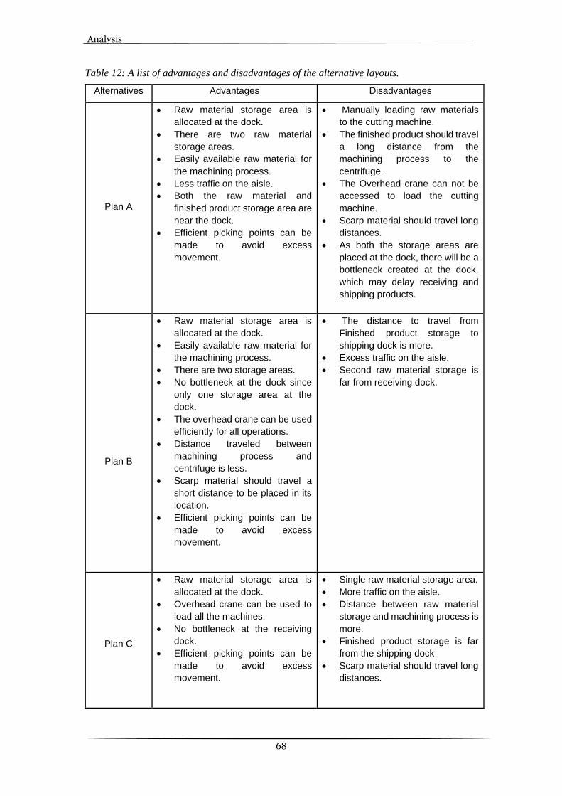
Analysis
68
Table 12: A list of advantages and disadvantages of the alternative layouts.
Alternatives Advantages Disadvantages
Plan A
• Raw material storage area is
allocated at the dock.
• There are two raw material
storage areas.
• Easily available raw material for
the machining process.
• Less traffic on the aisle.
• Both the raw material and
finished product storage area are
near the dock.
• Efficient picking points can be
made to avoid excess
movement.
• Manually loading raw materials
to the cutting machine.
• The finished product should travel
a long distance from the
machining process to the
centrifuge.
• The Overhead crane can not be
accessed to load the cutting
machine.
• Scarp material should travel long
distances.
• As both the storage areas are
placed at the dock, there will be a
bottleneck created at the dock,
which may delay receiving and
shipping products.
Plan B
• Raw material storage area is
allocated at the dock.
• Easily available raw material for
the machining process.
• There are two storage areas.
• No bottleneck at the dock since
only one storage area at the
dock.
• The overhead crane can be used
efficiently for all operations.
• Distance traveled between
machining process and
centrifuge is less.
• Scarp material should travel a
short distance to be placed in its
location.
• Efficient picking points can be
made to avoid excess
movement.
• The distance to travel from
Finished product storage to
shipping dock is more.
• Excess traffic on the aisle.
• Second raw material storage is
far from receiving dock.
Plan C
• Raw material storage area is
allocated at the dock.
• Overhead crane can be used to
load all the machines.
• No bottleneck at the receiving
dock.
• Efficient picking points can be
made to avoid excess
movement.
• Single raw material storage area.
• More traffic on the aisle.
• Distance between raw material
storage and machining process is
more.
• Finished product storage is far
from the shipping dock
• Scarp material should travel long
distances.

Analysis
69
The advantages and the disadvantages in Table 12 clearly show that Plan B is the most effective alternative of the three. Even though it has disadvantages, it has more advantages compared to the other two alternatives. Hence, Plan B is most suitable to be implemented in the future facility. As this method is not very accurate, the alternatives are evaluated once more using the WFA method. 2. Weighted Factor Analysis: Factor analysis is used to conduct a systematic evaluation of the alternate plans made. The factor analysis approach uses the principle of engineering to split the problems into smaller elements and evaluate them individually. This method follows the listing of factors that are considered important in evaluating the layout after discussing it with the company contact person. Further, the listed factors are weighted according to their importance compared to the other factors in Table 13. Once the factors have been weighted, the alternate plans should be rated provided one factor at a time. To avoid confusion and make it easier to rate, the rating method mentioned in the SLP method that is A, E, I, O, and U is used, as shown in Table 14. Finally, the weighted values and the rated values are multiplied to get a new rating, which is summed up to get the total value. This value depicts the difference between the alternatives and lets the evaluators understand which layout has turned out to be the best among the three alternatives.
Table 13: Weighted factor analysis of the alternative layouts.
Sl.no Factors Weight Plan A Plan B Plan C
1. Safety 8 I E E
2. Storage Effectiveness
10 A E I
3. The flow of material effectiveness
10 I E I
4. Material handling effectiveness
9 O A E
5. Space utilization 8 E E O
6. Flexibility of layout 7 O E A
7. Ease of Supervision and control
7 I A A
8. Maintenance problems
8 E E E
Total 221 284 246
24 32 32
50 40 30
30 40 30
18 45 36
32
32
16
14
28
35
21
35
35
32
32
32
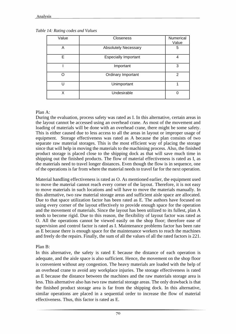
Analysis
70
Table 14: Rating codes and Values
Value Closeness Numerical Value
A Absolutely Necessary 5
E Especially Important 4
I Important 3
O Ordinary Important 2
U Unimportant 1
X Undesirable 0
Plan A: During the evaluation, process safety was rated as I. In this alternative, certain areas in the layout cannot be accessed using an overhead crane. As most of the movement and loading of materials will be done with an overhead crane, there might be some safety. This is either caused due to less access to all the areas in layout or improper usage of equipment. Storage effectiveness was rated as A because the plan consists of two separate raw material storages. This is the most efficient way of placing the storage since that will help in moving the materials to the machining process. Also, the finished product storage is placed close to the shipping dock as that will save much time in shipping out the finished products. The flow of material effectiveness is rated as I, as the materials need to travel longer distances. Even though the flow is in sequence, one of the operations is far from where the material needs to travel far for the next operation. Material handling effectiveness is rated as O. As mentioned earlier, the equipment used to move the material cannot reach every corner of the layout. Therefore, it is not easy to move materials in such locations and will have to move the materials manually. In this alternative, two raw material storage areas and sufficient aisle space are allocated. Due to that space utilization factor has been rated as E. The authors have focused on using every corner of the layout effectively to provide enough space for the operation and the movement of materials. Since the layout has been utilized to its fullest, plan A tends to become rigid. Due to this reason, the flexibility of layout factor was rated as O. All the operations cannot be viewed easily on the shop floor; therefore ease of supervision and control factor is rated as I. Maintenance problems factor has been rate as E because there is enough space for the maintenance workers to reach the machines and freely do the repairs. Finally, the sum of all the values of all the rated factors is 221.
Plan B:
In this alternative, the safety is rated E because the distance of each operation is
adequate, and the aisle space is also sufficient. Hence, the movement on the shop floor
is convenient without any congestion. The heavy materials are loaded with the help of
an overhead crane to avoid any workplace injuries. The storage effectiveness is rated
as E because the distance between the machines and the raw materials storage area is
less. This alternative also has two raw material storage areas. The only drawback is that
the finished product storage area is far from the shipping dock. In this alternative,
similar operations are placed in a sequential order to increase the flow of material
effectiveness. Thus, this factor is rated as E.

Analysis
71
The material handling effectiveness is rated A because, in this alternative, the material
handling system can be used more effectively compared to other alternatives. The heavy
raw materials from the storage area can be loaded easily with the help of an overhead
crane. The forklift trucks can be used to move the finished product from the cutting
process to the second raw material storage area if required. Space is also utilized more
effectively because sufficient space is made for the movement of materials and
personnel. Another raw material storage is made so the machining process can have
easy access. Hence the space utilization factor is rated E. As similar operations are
placed near each other, the machines can be moved around easily. Even the operations
are distributed on the layout equally, so the layout is not clustered in one area. Hence
the flexibility of the layout is rated as E. The whole shop floor can be supervised easily
as the operation is on both sides of the facility, making it more visible. Hence the
supervision factor is rated A. The machines also have enough space between them as
the whole process is widely laid out on the layout. This makes it easy for the workers
to do repairs on the machines easily without any congestion. Hence, the maintenance
problem factor is rated as E. Finally, the sum of all the rated factors' values is 284.
Plan C:
Since the operations and the machines are placed orderly with enough space between
them without any congestion, the safety factor is rated as E. This alternative has only
one raw material storage area, and the distance is far from few machines. The finished
product storage area is far from the shipping dock. Thus, the storage effectiveness is
rated I. The operations are placed sequentially, but the distance between some
operations is more. There is also backtracking and overlapping of material flow in this
alternative. Hence, the flow of material effectiveness is rated as I. The material handling
effectiveness is rated E in this alternative because the overhead crane is used efficiently
by loading the heavy materials in all the machines required. There is also enough space
provided on the shop floor for the forklift trucks to move.
The space utilization is rated O because this alternative has only one raw material
storage area. The flexibility of the layout is rated as A because all the operations are
laid out around the whole facility equally, so the machines of the same process can
accommodate any changes required. As this alternative has a wide aisle space and the
operations are placed on both sides of the layout, the supervisor can have clear visibility
of the whole workplace. Thus, the supervision factor is rated as A. Enough space is
provided for each operation to repair the machines without any hassle. Hence, the
maintenance problem factor is rated as E. Finally, the sum of all the rated factors' values
is 246.
Discussion
72
6 Discussion This chapter provides a discussion of the analyzed findings concerning the literature. A thorough discussion will be done on all the topics and the layout plan to answer the research question.
6.1 Discussion of methods
To address the research issues of the project and eventually accomplish the project
objective, a systematic way to perform the study was deemed essential. The study area
was explorative, which led us to have a wide literature review about layout planning
and lean manufacturing tools. Furthermore, the study was validated and made reliable
by increasing the number of methods to collect data and analyze it using the best
techniques.
To better understand the current state of the facility and find the best methods to plan
the new layout, an in-depth literature study and brainstorming were done. The
brainstorming method was constantly used to find the right way of working and use the
best source to be used. Furthermore, the authors of this report have considered a case
study as an appropriate research method to explore the problems encountered in the
present facility. As a fundamental practice, a literature study was conducted to get more
insights about the subject area to form a relationship between the theory and the real-
life situation. The authors had all the freedom to gather all the theoretical data necessary
to proceed with the research study. Therefore, the case study approach led the authors
to use many different methods to collect data and use it accordingly whenever
necessary.
Amid COVID-19, all the data had to be collected through Semi-structured interviews
conducted through video conferencing. A semi-structured interview was mostly
conducted with the company's CEO since few employees are working on the shop floor.
A series of discussion questions were made to guide the interview, making it more
comfortable for the CEO to discuss those questions. This type of interview allowed the
authors to create follow-up questions for the next interview and help form survey
questions for the shop floor workers.
Due to the same restriction mentioned above, the authors could not visit the facility to
do observations; thus, a video of the facility was made and provided by the CEO. This
method was very beneficial since the recorded video can be used multiple times to be
reviewed carefully during the current situation. Therefore, the observation method
using videography is the best solution when there is a far distance between the authors
and the case company. To understand more clearly, the authors decided to use another
tool to collect data through the document review method. To make the information
collected more valid, the authors had to conduct a document review that the company
provided and substantiate the interviews and video observation data.
Finally, the SLP method was discovered to be the best method in planning the layout
systematically also incorporating lean tools to the new facility. This method consists of
several simple steps that completely depend on qualitative data, making it easier for the
authors to continue with the study and plan a new layout for the case company. Further,
Discussion
73
the literature review and brainstorming methods were an ongoing process throughout
the report that allowed the authors to compare the data collected with the empirical data.
6.2 Discussion of findings and analysis
SME’s have been struggling with the current changes in demand in the market, due to
which they encounter similar problems or challenges as mentioned in the findings
chapter. Thus, there is a commonality between the case company and other SME’s
conducting similar operations because of similar problems. These challenges can be
resolved by planning an efficient layout by using the methods mentioned in this study.
Furthermore, the discussion of findings and analysis is done in three separate sections
wherein a detailed description of the three research questions will be provided. This
section will begin with a detailed description and discussion about research questions
and follow the same rule to write about the second and third research questions.
RQ-1: What are the challenges faced in the current layout?
The challenges faced in the current facility include safety, storage effectiveness, the
flow of materials, material handling effectiveness, space utilization, flexibility of the
layouts, ease of supervision, maintenance problems.
For any effective change in the system to occur, it is important to figure out the current
circumstances, challenges, and issues in the system. A system has to be closely
analyzed so that the method is well understood. Therefore, the authors of this report
formulated research question one so that it leads to discovering all the challenges faced
in the current facility. These challenges were identified with the help of all the methods
used to gather data. The challenges that are identified go in line with the literature used
in the study.
• Safety: To make the workplace safer, the company should focus on using better material handling equipment and allocate enough working space. It was discovered from the survey, interviews, and observations that there is only one pallet jack forklift and one warehouse forklift. Further, it was also noted that there was too much congestion due to a lack of proper allocation of areas. Due to these reasons, the safety of workers was at risk; therefore, an attempt has to be made to resolve this issue in the new layout. Increasing the number of forklifts to be used could be one solution, but that does not resolve the other problem. There must be enough space provided between the machines where the workers can move freely. This congestion can also cause ergonomic issues, which may cause injuries to the workers. Hence allocating sufficient space to the machine and workers become a necessary thing to be done.
• Storage effectiveness: As per the information, storage effectiveness is very less as they had to make another storage place in the basement. This became a problem when they had to get material from the basement to the shopfloor. The space for storage on the shop floor was not enough, and due to that, the workers had to get material from the basement multiple times. This process was not efficient and also would consume much time during the process. Therefore, it

Discussion
74
becomes necessary that appropriate space should be allocated to the storage area so that its effectiveness can be high.
• The flow of material effectiveness: The current layout of the company is not in
a regular form; instead, it is in an L-shape. Though the operations are in sequence, the placement of machines is not done effectively. Due to which the flow of material is also disrupted as it has to travel multiple times and long distances. The current layout is not flexible enough to change its layout; therefore, the machines were not placed appropriately. Hence to have an effective flow of material, the company needs to focus on the placement of machines that matches the sequence of operations.
• Material handling effectiveness: As mentioned earlier, there are only two
forklifts in the entire layout, of which the only one can be used on the shop floor. Using one forklift for the entire shop floor is ineffective as it will cause unnecessary workers' movement and idle time increases. The overhead crane is used only to move raw materials from receiving dock to raw material storage. Heavy materials are loaded into the machines manually, which may lead to injuries. Therefore, there are multiple movements of materials which makes the material handling less effective. This issue becomes a primary focus for the company to resolve if they need to improve productivity and effectiveness. Thus, installing extra forklifts on the shop floor can help in reducing the unnecessary movement of workers and improve the effectiveness of material handling.
• Space utilization: In the current facility, the space allocated to the machines is
not effective. It is very congested for the workers to move between the machines to load material and collect the finished products. This depicts how congested the shop floor is and how poorly space is allocated. Due to less space allocated, it becomes difficult even to conduct maintenance work as well. Therefore, the proper study of space is needed and efficiently allocate appropriate space for each machine.
• The flexibility of the layout: since the layout is somewhat in L-shape, it
becomes very difficult to change the existing or add new processes. The current layout has been poorly distributed, which hinders the flexibility of the layout. The area allocated to each machine is not effective enough to be replaced at any given point in time. Therefore, the company needs to focus on arranging the machines so that it can make the layout flexible enough to adjust to any changes in the future.
• Ease of supervision: There is a poor vision for supervision as the working areas
are divided with a wall. This makes it difficult to have easy visibility for the management to keep an eye on all the operators and operations. To avoid this, the entire shopfloor should be in the same area, which can be visible to the management from any place.
• Maintenance problems: During the observation, it was noticed that there were
many materials placed in the aisleway, which is not a standard way of placing the material. Though the maintenance was done daily, it was a difficult task to accomplish due to congestion. Maintenance not only means keeping the machine running but as keeping the workstations clean. There is a need to

Discussion
75
develop that thinking and have a standardized way of working on the shop floor. By implementing such standards, maintenance problems can be avoided easily.
RQ-2: Which is the best layout among the alternative layouts?
Different alternative layouts are developed with the help of a relationship chart and
relationship diagram. One of the best alternatives will be selected, which will be
implemented in the future facility. To select the best alternative, they must be compared
and evaluated. This is done by two methods, advantages versus disadvantages and the
WFA method.
The first method is done by identifying the advantages and disadvantages of the
alternative layouts. This method is one of the easiest and the least accurate methods as
it is a simple listing of pros and cons in a table for each alternative. Hence, it is used as
a preliminary screening of the alternatives when sufficient data is not available. This is
because the project is done completely online, as the researchers are not allowed to visit
the facility due to the present COVID-19 situation. This procedure consumes less time
and is effective most of the time when it is rough and early screening of the alternatives.
After listing the advantages and disadvantages, Plan B is the most suitable layout for
the future facility. Even though Plan B has disadvantages, it is less when compared to
other alternatives. Plan B also has a second raw material storage area, and all the
machines in the machining process have easy access to it. But this is just a preliminary
screening as the alternatives will be evaluated more thoroughly with another evaluating
method to make the recommendation more credible. Table 15 shows a few of the
differences between the alternatives.
Table 15: Difference between the alternative Layouts
Plan A Plan B Plan C
Two raw material storage area that is easily accessible to the machines.
Two raw material storage area that is easily accessible to the machines.
Single raw material storage area. Hence the raw materials should travel a long distance to reach the machines far from the storage area.
The Overhead crane cannot be accessed to load the cutting machine.
Overhead crane can be used efficiently for all the required operations.
Overhead crane can be used efficiently for all the required operations.
The finished product storage area is very close to the shipping area.
The finished product storage area is a bit far from the shipping area.
The finished product storage area is far from the shipping area.
Material from the machining process should travel a long distance to the centrifuge.
Material from the machining process should travel less distance to the centrifuge.
Material from the machining process should travel a long distance to the centrifuge.
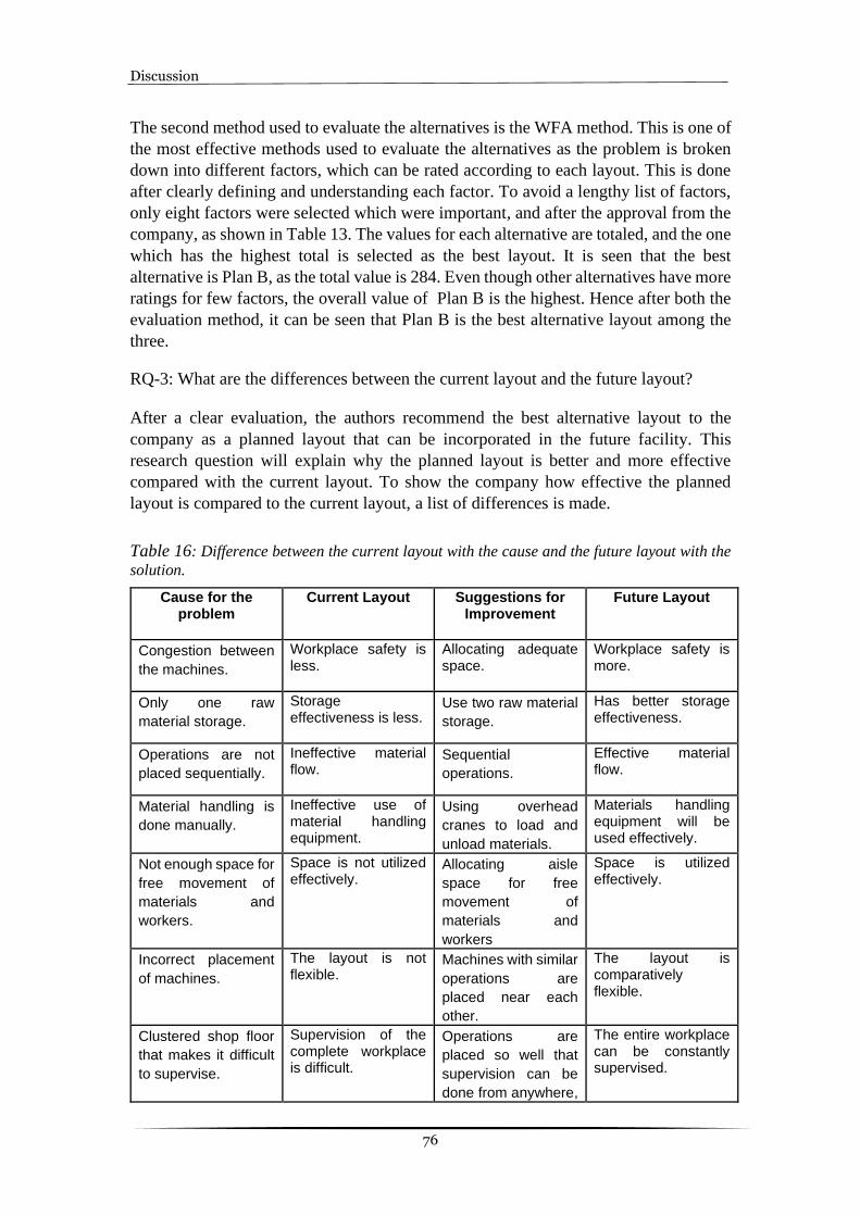
Discussion
76
The second method used to evaluate the alternatives is the WFA method. This is one of
the most effective methods used to evaluate the alternatives as the problem is broken
down into different factors, which can be rated according to each layout. This is done
after clearly defining and understanding each factor. To avoid a lengthy list of factors,
only eight factors were selected which were important, and after the approval from the
company, as shown in Table 13. The values for each alternative are totaled, and the one
which has the highest total is selected as the best layout. It is seen that the best
alternative is Plan B, as the total value is 284. Even though other alternatives have more
ratings for few factors, the overall value of Plan B is the highest. Hence after both the
evaluation method, it can be seen that Plan B is the best alternative layout among the
three.
RQ-3: What are the differences between the current layout and the future layout?
After a clear evaluation, the authors recommend the best alternative layout to the
company as a planned layout that can be incorporated in the future facility. This
research question will explain why the planned layout is better and more effective
compared with the current layout. To show the company how effective the planned
layout is compared to the current layout, a list of differences is made.
Table 16: Difference between the current layout with the cause and the future layout with the
solution.
Cause for the problem
Current Layout Suggestions for Improvement
Future Layout
Congestion between
the machines.
Workplace safety is less.
Allocating adequate space.
Workplace safety is more.
Only one raw
material storage.
Storage effectiveness is less.
Use two raw material
storage.
Has better storage effectiveness.
Operations are not
placed sequentially.
Ineffective material flow.
Sequential
operations.
Effective material flow.
Material handling is
done manually.
Ineffective use of material handling equipment.
Using overhead
cranes to load and
unload materials.
Materials handling equipment will be used effectively.
Not enough space for
free movement of
materials and
workers.
Space is not utilized effectively.
Allocating aisle
space for free
movement of
materials and
workers
Space is utilized effectively.
Incorrect placement
of machines.
The layout is not flexible.
Machines with similar
operations are
placed near each
other.
The layout is comparatively flexible.
Clustered shop floor
that makes it difficult
to supervise.
Supervision of the complete workplace is difficult.
Operations are
placed so well that
supervision can be
done from anywhere,
The entire workplace can be constantly supervised.

Discussion
77
and all the operations
are visible.
Due to congestion
between machines.
Maintenance problems are faced.
Appropriate space
between the
machines should be
allocated.
Fewer maintenance problems will be faced.
Table 17: Difference in Weighted factor analysis between the current layout and the future
layout.
SL No. Factors Weight Current Layout
Future Layout
1. Safety 8 I E
2. Storage Effectiveness 10 O E
3. The flow of material effectiveness
10 O E
4. Material handling effectiveness 9 O A
5. Space utilization 8 I E
6. Flexibility of layout 7 O E
7. Ease of supervision and control 7 I A
8. Maintenance problems 8 I E
Total 165 284
Table 16 and Table 17 shows how the future layout is well planned compared to the
current layout. The score from the WFA method also shows that the future facility has
a better score when compared to the current facility. The score of the current facility is
165, and the future facility is 284. There is a significant difference in the scores. This
huge difference in scores is because the challenges faced in the current layout are
improved and presented in the future layout.
The safety in the planned layout is increased by placing the operations with adequate
space between them. This leads to less congestion so the workers can move around the
24 32
20 40
20
18
40
45
24 32
14 28
21 35
24 32

Discussion
78
shop floor conveniently. The raw material storage is more effective in the planned
layout because it has two raw material storage areas. These are in a short distance for
both types of machines of the machining process. The material flow is also more
effective in the planned layout because the machines with similar functions are placed
together and in sequential order. Hence the materials will follow the same pattern
throughout the process. This will decrease the crossflow or backtracking of the
materials.
The current layout will not have a better material handling effectiveness because the
CNC machines are loaded manually in the current facility, which might lead to injuries
or a decrease in the quality. Hence, the overhead crane will be used more effectively to
load all the heavy raw materials into the machines in the planned layout. The planned
layout space will be utilized effectively as there is sufficient space for the movement of
materials, forklifts, and personnel on the shop floor. A provision is also made for the
storage of raw materials near the machines to be easily accessible. In the planned layout,
all the machines with similar operations are placed near each other. This makes it easy
to move the machines around and to accommodate any changes easily. The operations
are laid out around the facility without making it more clustered in one particular area.
Hence, the planned layout will be comparatively flexible than the current layout.
As the current facility is more congested and machines of the same operations are not
placed near each other, the supervision of the whole process is not possible. In the
planned layout, all the operations have to be placed in a way where the complete
workplace is visible, and it will be easy for supervision. The supervisor can
conveniently move around the facility as there is enough space between the operations
and a wide aisle. A specific space for the maintenance workshop is allotted in the
planned layout, which will not interfere with the other operations. The machines also
have enough space between them so the machine repairs can be done without any
hassle, unlike the current layout.

Conclusion
79
7 Conclusion
This study outlines different approaches that have been used to generate compelling
results from a single case study. A mix of existing methods has been incorporated, such
as SLP, material handling systems, lean manufacturing tools, and WFA. In particular,
the authors have attempted to provide some insight, suggestions, and thorough
guidance, for implementing the methods in planning the layout.
Numerous aspects influence a production system's efficiency and productivity.
However, the plant layout system is a crucial aspect of the production system that many
SMEs overlook. Hence, this study aims to plan a production layout for the SME using
SLP as a tool. Along with SLP, material handling systems and lean manufacturing tools
are considered while planning to have an efficient layout for the SME. This is done to
overcome most of the challenges faced by the SME.
Three research questions were established at the start of the project to act as guides, and
they were based on the project goal and objective. Because the project was started
without prior knowledge of the manufacturing system and potential challenges, the
questions were of an investigative nature.
RQ-1: What are the challenges faced in the current layout?
To analyze the effectiveness of the current facility, an evaluation is performed after
considering all the factors in the current production process. With this, the challenges
faced in the current facility are detected. Hence, to minimize all the identified
challenges, an effective layout with appropriate solutions should be planned, which can
be implemented in the future facility.
RQ-2: Which is the best layout among the alternative layouts?
The best layout among the alternatives is plan B. This is done after carefully evaluating
the alternative layouts with different methods. The following points show why Plan B
was selected as the best alternative:
• Better use of material handling system.
• Better usage of space.
• The material travels a short distance.
• Scrap travels a short distance.
• Less overlapping of material flow
RQ-3: What are the differences between the current layout and the future layout?
The SLP method is used to plan the future layout, which is more efficient. In the
recommended layout plan, the material handling system has been improved by
incorporating few material handling principles. The wastes identified are also
eliminated by incorporating lean principles to overcome those wastes. The workplace
is standardized with the help of lean manufacturing tools such as 5S and visual
management. This will help improving communication and keep transparency on the
shop floor.

Conclusion
80
The advice we argue will help address some of the challenges faced in SMEs. These
techniques have the capacity to involve everyone, including higher management which
improves the study. To summarize, this report provides the detailed steps necessary to
be followed and some associated suggestions for their application. The authors
sincerely hope that this report could make an impact on conducting only a qualitative
study and still achieving the desired results for the SME’s.
7.1 Recommendations
The decreased layout efficiency of the current facility highlights the need for a more
efficient production layout in the future facility. The company's future goal as a
precision part producer requires developing a manufacturing system to be competitive.
As a result, the thesis recommends that REHOBOT Rotex AB apply the suggested final
layout and the improvements. The proposed layout would result in a more efficient
material handling system and manufacturing flow. If the suggested layout is currently
difficult to implement, the suggested improvements should be implemented as the first
step.
The suggested material handling improvements are:
• Sequential operation. • Direct material movement. • Place machining process near storage. • Operations close to each other. • Stack the raw materials vertically. • Place finished products on shelves. • Clean the storage area and dispose of waste regularly. • Load heavy materials with overhead crane. • Use the forklifts when needed. • Avoid overloading of the crane. • Regular maintenance of equipment. • Train the operators. • Avoid using defective equipment.
The suggested lean improvements are:
It is recommended to implement 5S to have an organized workplace where all the
activities are done systematically. This will also help in increasing the worker's morale
that will, in turn, increase their productivity. Along with 5S, it is better to implement
visual management since they go hand in hand. Visual management should be
implemented as follows:
• Simple information flow- Display material flow in the form of a flow chart. • Information at the point of use –Display instructions to use tools and
equipment. • Empowers employees- Display information about lean practices which they
can learn. • Improves communication and feedback- Provide information about the
operations. • Increased transparency- Conduct meetings with workers. • Disciplined workplace- Display standard rules to be followed.

Conclusion
81
7.2 Future Scope
Due to the project's time constraints and some uncertainties before the research started,
some fields within the study were not investigated in greater depth. This report will
provide a general layout plan for the case company. The implementation of the planned
layout will not be a part of this report. The following are the different topics that further
research can be done.
• Detailed planning of the layout. • Implementation of the planned layout. • Practical Evaluation after implementing the planned layout. • Evaluation of planned layout using Cost comparison method. • Challenges faced when relocating the facility.
References
82
8 References
Al-Samarraie, H., & Hurmuzan, S. (2018). A review of brainstorming techniques in
higher education. Thinking Skills and Creativity, 27(November 2017), 78–91.
https://doi.org/10.1016/j.tsc.2017.12.002
Ali Naqvi, S. A., Fahad, M., Atir, M., Zubair, M., & Shehzad, M. M. (2016).
Productivity improvement of a manufacturing facility using systematic layout
planning. Cogent Engineering, 3(1).
https://doi.org/10.1080/23311916.2016.1207296
Arunyanart, S., & Pruekthaisong, S. (2018). Selection of multi-criteria plant layout
design by combining AHP and DEA methodologies. MATEC Web of Conferences,
192. https://doi.org/10.1051/matecconf/201819201033
Bayo-Moriones, A., Bello-Pintado, A., & de Cerio, J. M. D. (2010). 5S use in
manufacturing plants: Contextual factors and impact on operating performance.
International Journal of Quality and Reliability Management, 27(2), 217–230.
https://doi.org/10.1108/02656711011014320
Bellgran, M., & Säfsten, K. (2010). Production Development. Production
Development. https://doi.org/10.1007/978-1-84882-495-9
Bowen, G. A. (2009). Document analysis as a qualitative research method. Qualitative
Research Journal, 9(2), 27–40. https://doi.org/10.3316/QRJ0902027
Brattberg, J., & Mathew, N. T. (2018). Redesigning the Layout of a Final Flow in a
Production System. Production Engineering, 1, 56.
Campos, V. M. K., Cotrim, S. L., Galdamez, E. V. C., & Leal, G. C. L. (2016).
Introduction of Lean Manufacturing Philosophy By Kaizen Event: Case Study on
a Metalmechanical Industry. Independent Journal of Management & Production,
7(1), 151–168. https://doi.org/10.14807/ijmp.v7i1.388
Chee Houa, S., Haslinda, M., Muliati, S., Mariam Miri, A., & Rahim, A. F. (2018).
Implementation of 5S in Manufacturing Industry: A Case of Foreign Workers in
Melaka. MATEC Web of Conferences, 150, 1–6.
https://doi.org/10.1051/matecconf/201815005034
Chiarini, A., Baccarani, C., & Mascherpa, V. (2018). Lean production, Toyota
Production System and Kaizen philosophy: A conceptual analysis from the
perspective of Zen Buddhism. TQM Journal, 30(4), 425–438.
https://doi.org/10.1108/TQM-12-2017-0178
Christensen, J. & T. (2015). Chapter 4: Ethics in Scientific Research. Research
Methods, Design and Analysis, 2002, 110–148.
Covington, W. G., & JR., P. (2012). Reproduced with permission of the copyright
owner . Further reproduction prohibited without. Journal of Allergy and Clinical
Immunology, 130(2), 556. http://dx.doi.org/10.1016/j.jaci.2012.05.050
Cronin, C., Awasthi, A., Conway, A., O’Riordan, D., & Walsh, J. (2020). Design and
development of a material handling system for an autonomous intelligent vehicle
for flexible manufacturing. Procedia Manufacturing, 51(2019), 493–500.
https://doi.org/10.1016/j.promfg.2020.10.069
De Carlo, F., Arleo, M. A., Borgia, O., & Tucci, M. (2013). Layout design for a low
capacity manufacturing line: A case study. International Journal of Engineering

References
83
Business Management, 5(SPL.ISSUE). https://doi.org/10.5772/56883
Deros, B. M., Daruis, D. D. I., & Basir, I. M. (2015). A Study on Ergonomic Awareness
among Workers Performing Manual Material Handling Activities. Procedia -
Social and Behavioral Sciences, 195, 1666–1673.
https://doi.org/10.1016/j.sbspro.2015.06.238
Desai, M. S., & Johnson, R. A. (2013). Using a fishbone diagram to develop change
management strategies to achieve first-year student persistence.pdf. SAM
Advanced Managment Journal, 51–64.
Deshmukh, G., Patil, C. R., & Deshmukh, M. G. (2017). Manufacturing industry
performance based on lean production principles. 2017 International Conference
on Nascent Technologies in Engineering, ICNTE 2017 - Proceedings, 1–6.
https://doi.org/10.1109/ICNTE.2017.7947977
Djassemi, M. (2007). Improving factory layout under a mixed floor and overhead
material handling condition. Journal of Manufacturing Technology Management,
18(3), 281–291. https://doi.org/10.1108/17410380710730611
Drira, A., Pierreval, H., & Hajri-Gabouj, S. (2007). Facility layout problems: A survey.
Annual Reviews in Control, 31(2), 255–267.
https://doi.org/10.1016/j.arcontrol.2007.04.001
Eaidgah Torghabehi, Y., Maki, A. A., Kurczewski, K., & Abdekhodaee, A. (2016).
Visual management, performance management and continuous improvement: A
lean manufacturing approach. International Journal of Lean Six Sigma, 7(2), 187–
210. https://doi.org/10.1108/IJLSS-09-2014-0028
Eisenhardt, K. M. (1989). Building Theories from Case Study Research. Academy of
Management Review, 14(4), 532–550. https://doi.org/10.5465/amr.1989.4308385
Engelseth, P., & Gundersen, D. (2018). Lean and complex systems: A case study of
materials handling at an on-land warehouse facility supporting subsea gas
operations. International Journal of Design and Nature and Ecodynamics, 13(2),
199–207. https://doi.org/10.2495/DNE-V13-N2-199-207
Febriandini, I. F., & Yuniaristanto. (2019). Re-design Facility Layout using Systematic
Layout Planning Method: A Case Study : ro Cosmeceutical Sdn. Bhd. IOP
Conference Series: Materials Science and Engineering, 495(1).
https://doi.org/10.1088/1757-899X/495/1/012027
Hammersley, M. (1987). Some Notes on the Terms ’ Validity ’ and ’ Reliability ’
Author ( s ): Martyn Hammersley Published by : Wiley on behalf of BERA Stable
URL : http://www.jstor.org/stable/1501231 Some Notes on the Terms ’ Validity ’.
British Educational Research Journal, 13(1), 73–81.
Hassan, M. M. D. (2010). A framework for selection of material handling equipment in
manufacturing and logistics facilities. Journal of Manufacturing Technology
Management, 21(2), 246–268. https://doi.org/10.1108/17410381011014396
Heale, R., & Twycross, A. (2015). Validity and reliability in quantitative studies.
Evidence-Based Nursing, 18(3), 66–67. https://doi.org/10.1136/eb-2015-102129
Hewson, C., & Hewson, C. (2014). Qualitative Approaches in Internet-Mediated
Research. The Oxford Handbook of Qualitative Research, March, 422–452.
https://doi.org/10.1093/oxfordhb/9780199811755.013.020
Hoernicke, M., Fay, A., & Barth, M. (2015). Virtual plants for brown-field projects:
Automated generation of simulation models based on existing engineering data.

References
84
IEEE International Conference on Emerging Technologies and Factory
Automation, ETFA, 2015-Octob. https://doi.org/10.1109/ETFA.2015.7301462
Ilie, G., & Ciocoiu, C. N. (2010). Ilie G. and. Ciocoiu C.N. Application of fishbone
diagram to determine the risk of an event with multiple causes management
research application of fishbone diagram to determine the risk of an event with
multiple causes. Management Research and Practice, 2(1), 1–20.
http://mrp.ase.ro/no21/f1.pdf
Ioannou, G. (2007). An integrated model and a decomposition-based approach for
concurrent layout and material handling system design. Computers and Industrial
Engineering, 52(4), 459–485. https://doi.org/10.1016/j.cie.2007.02.003
Johnson, B. R., & D’Lauro, C. J. (2018). After Brainstorming, Groups Select an Early
Generated Idea as Their Best Idea. Small Group Research, 49(2), 177–194.
https://doi.org/10.1177/1046496417720285
Jonsen, K., & Jehn, K. A. (2009). Using triangulation to validate themes in qualitative
studies. Qualitative Research in Organizations and Management: An
International Journal, 4(2), 123–150.
https://doi.org/10.1108/17465640910978391
Knoblauch, H., & Schnettler, B. (2012). Videography: Analysing video data as a
“focused” ethnographic and hermeneutical exercise. Qualitative Research, 12(3),
334–356. https://doi.org/10.1177/1468794111436147
Kulkarni, M. H., Bhatwadekar, S. G., & Thakur, H. M. (2015). A literature review of
facility planning and plant layouts. International Journal of Engineering Sciences
& Research Technology, 4(3), 35–42. http:%5Cnwww.ijesrt.com©
Kurpjuweit, S., Reinerth, D., Schmidt, C. G., & Wagner, S. M. (2019). Implementing
visual management for continuous improvement: barriers, success factors and best
practices. International Journal of Production Research, 57(17), 5574–5588.
https://doi.org/10.1080/00207543.2018.1553315
Liskin, J. E. (1979). Review Policy. Language Learning, 29(2), 409–410.
https://doi.org/10.1111/j.1467-1770.1979.tb01081.x
Litchfield, R. C. (2009). Brainstorming rules as assigned goals: Does brainstorming
really improve idea quantity? Motivation and Emotion, 33(1), 25–31.
https://doi.org/10.1007/s11031-008-9109-x
Louis Cohen, Lawrence Manion, K. M. (2014). Research Methods in Education . Sixth
Edition by Louis Cohen ; Lawrence Manion ; Keith Morrison Review by :
Alejandra Navarro Sada and Antonio Maldonado Published by : Taylor & Francis
, Ltd . on behalf of the Society for Educational Studies. 55(4), 469–470.
Luo, T., Wu, C., & Duan, L. (2018). Fishbone diagram and risk matrix analysis method
and its application in safety assessment of natural gas spherical tank. Journal of
Cleaner Production, 174, 296–304. https://doi.org/10.1016/j.jclepro.2017.10.334
Mikhail, D., & Sadllah, S. (2020). A study on layout design for a logistic center – Case
study at ASSA ABLOY Opening Solutions.
Muther, R., & Hales, L. (1981). Systematic layout planning. In Journal of Chemical
Information and Modeling (Vol. 53, Issue 9).
Ning, X., Qi, J., & Wu, C. (2018). A quantitative safety risk assessment model for
construction site layout planning. Safety Science, 104(February), 246–259.
https://doi.org/10.1016/j.ssci.2018.01.016

References
85
Ondiek, G. (2005). Assessment of materials management in the Kenyan manufacturing
firms-Exploratory survey of manufacturing firms based in Nairobi. Journal of
Business Studies Quarterly, 3(3), 40–49.
http://erepository.uonbi.ac.ke/handle/11295/40766
Ortiz, C. A. (2015). The 5S Playbook. In The 5S Playbook.
https://doi.org/10.1201/b18843
Potter, W. J., & Levine-Donnerstein, D. (1999). Rethinking validity and reliability in
content analysis. Journal of Applied Communication Research, 27(3), 258–284.
https://doi.org/10.1080/00909889909365539
Pratami, D., Iqbal, M., Puspita, I. A., Dermawan, M. R., & Arief, R. K. F. (2017). The
development of plant layout design framework. Advanced Science Letters, 23(5),
4281–4286. https://doi.org/10.1166/asl.2017.8254
Putri, N. T., & Dona, L. S. (2019). Application of lean manufacturing concept for
redesigning facilities layout in Indonesian home-food industry: A case study. TQM
Journal, 31(5), 815–830. https://doi.org/10.1108/TQM-02-2019-0033
Rami Alghalayini. (2020). Improving an internal material handling system . A case
study of a Swedish company in food industry . July, 1–63.
Rapley, T. J., & Rapley, T. J. (1994). Q r 303. Most.
Ray, & Sidharatha. (2019). Introduction to Materials Handling 1.1. 1–8.
Ray, & Sidharatha. (2019). Principles of Materials Handling 2.0. 9–15.
Saunders mark, Lewis Philip, T. A. (2016). Research Methods for Business Students
Seventh edition (P. E. Limited (ed.); 7th editio).
Sayers, R. (2003). Informed research made easy: Williamson, Kirsty et al. Research
methods for students, academics and professionals: information management and
systems. 2nd ed. Wagga Wagga, NSW: Centre for Information Studies, 2002.
352p A$66.0. The Australian Library Journal, 52(4), 406–407.
https://doi.org/10.1080/00049670.2003.10721601
Shah, R., & Ward, P. T. (2007). Defining and developing measures of lean production.
Journal of Operations Management, 25(4), 785–805.
https://doi.org/10.1016/j.jom.2007.01.019
Singh, Sanjay. (2012). Ethics in research. Indian Journal of Dermatology, Venereology
and Leprology, 78(4), 411–413. https://doi.org/10.4103/0378-6323.98069
Singh, Shivam, & Khanduja, D. (2019). Improvement in Manufacturing System by
Rearrangement in Layout Design - A Case Study. Journal of Physics: Conference
Series, 1240(1). https://doi.org/10.1088/1742-6596/1240/1/012023
Snyder, H. (2019). Literature review as a research methodology: An overview and
guidelines. Journal of Business Research, 104(July), 333–339.
https://doi.org/10.1016/j.jbusres.2019.07.039
Suhardini, D., Septiani, W., & Fauziah, S. (2017). Design and Simulation Plant Layout
Using Systematic Layout Planning. IOP Conference Series: Materials Science and
Engineering, 277(1). https://doi.org/10.1088/1757-899X/277/1/012051
Sykes, D. (1994). Planning for Excellence in Materials Handling. Logistics Information
Management, 7(6), 10–12. https://doi.org/10.1108/09576059410071763
Watanapa, A., & Wiyaratn, W. (2012). Systematic layout planning to assist plant
layout: Case study pulley factory. Applied Mechanics and Materials, 110–116,

References
86
3952–3956. https://doi.org/10.4028/www.scientific.net/AMM.110-116.3952
Yin, R., & Yin, R. (2016). Chapter 6 – Case Study. Theory and Methods of
Metallurgical Process Integration, 179–272.
Zachariadis, M., Scott, S., & Barrett, M. (2013). Methodological implications of critical
realism for mixed-methods research. MIS Quarterly: Management Information
Systems, 37(3), 855–880. https://doi.org/10.25300/misq/2013/37.3.09
Zakirah, T., Emeraldi, R., Handi, O. M., Danil, D., & Kasih, T. P. (2018). Warehouse
layout and workflow designing at PT. PMS using systematic layout planning
method. IOP Conference Series: Earth and Environmental Science, 195(1).
https://doi.org/10.1088/1755-1315/195/1/012026
Zhang, B., Niu, Z., & Liu, C. (2020). Lean tools, knowledge management, and lean
sustainability: The moderating effects of study conventions. Sustainability
(Switzerland), 12(3). https://doi.org/10.3390/su12030956
Zhou, B. (2016). Lean principles, practices, and impacts: a study on small and medium-
sized enterprises (SMEs). Annals of Operations Research, 241(1–2), 457–474.
https://doi.org/10.1007/s10479-012-1177-3

Appendices
87
9 Appendices
Appendix 1: CEO interview guide
1. What type of parts will be produced in your new factory?
2. Do you have any general aim, purpose, and vision for the new production
flow?
3. In what part of your new production plant you want us to focus our project?
4. Have you implemented lean principles in your current production? If yes, then
in which part of your production have you implemented lean?
5. What are the challenges you are facing in the current production flow?
6. How many working machines are there in your facility, and how many machines
are you planning to use in the new facility?
7. How many employees are working at present, and how many employees would
work in the new facility?
8. What is the present plant capacity , and what will be the new plant capacity?
9. What are the sustainable factors you have implemented in your current facility?
10. What type of layout are you using in the current production line?
11. Do you want a fully automated production line or a semi-automated production
line?
12. What maintenance principle are you using in your production line?
13. How is the material flow in the present production line?
14. Have you come across any challenges concerning material flow?
Note: Please send us a video of the process flow and also a production layout map of
your present facility.

Appendices
88
Appendix 2: Survey questions for shopfloor workers.
1. According to you, rate the safety measures in the facility.
2. According to you rate the shop floor layout.
3. According to you rate the movement of raw material to the machines.
4. According to you rate the movement of finished products from the machines to
packaging.
5. According to you, it is easy to move around on the shop floor.
6. Is there any physical pain you experience in moving the parts from one machine
to another?
7. Is there any delay in production due to a shortage of materials?
8. Do you feel physical stress when moving materials?
9. Do you feel there is too much movement between the machines?
10. Are there any challenges you face during the work?
11. Do you have any suggestions to improve the layout?

Appendices
89
Appendix 3: Current layout map

Appendices
90
Appendix 4: A list of the factors most commonly involved follows – not in the order of
importance.
1. Ease of future expansion.
2. Adaptability and versatility.
3. The flexibility of layout.
4. The flow of materials effectiveness.
5. Materials handling effectiveness.
6. Storage effectiveness.
7. Space utilization.
8. Effectiveness of supporting service integration.
9. Safety and housekeeping.
10. Working conditions and employee satisfaction.
11. Ease of supervision and control.
12. Appearance, promotional value, public or community relations.
13. Quality of product.
14. Maintenance problems.
15. Fit with company organization structure.
16. Equipment utilization.
17. Utilization of natural conditions or surroundings.
18. Ability to meet capacity or requirements.
19. Plant security and pilferage.
20. Compatibility with long-range company plans.

Appendices
91
Appendix 5 :A list of machines with their dimensions.
1. Automatic Cutting Machine – 3.37 m2
2. Manual Cutting Machine – 7.15 m2
3. CNC Machine – 7.7 m2
4. Rotex Machine – 1.12 m2
5. Big Lathe – 15.3 m2
6. Small Lathe – 6.05 m2
7. Small Centrifuge – 1 m2
8. Big Centrifuge – 21 m2
9. Shaker – 0.9 m2
10. Small Washing Machine – 4.8 m2
11. Big Washing Machine – 20 m2