plasmon m-series m500 optical disk library system scsi ... · plasmon m500 library system scsi...
TRANSCRIPT
Document No. 304437F
Plasmon M-Series M500Optical Disk Library System
SCSI Software Interface Specification
Plasmon IDE


Plasmon M500 Library System
SCSI Software Interface Specification
This publication describes the SCSI software interface to Plasmon’s M500 Optical Disk Library System -an automated optical disk cartridge changer. It is intended to provide interfacing information to partieswishing to develop software and/or applications programs for the M500 library system. This documentcorresponds to product revision level 2.05 or later of the M500 firmware.
Information in this document is subject to change without notice and does not represent a commitment onthe part of Plasmon.
Plasmon has a material and substantial proprietary interest in the design of its controller interface and anyinformation or software it may supply. The supply of this publication does not convey to the recipientany license under Plasmon’s patent rights or proprietary designs.
At the time of release, the information in this publication was as accurate and current as possible.Plasmon assumes no responsibility for any error which may appear herein beyond that of providingcorrected information when errors are brought to its attention. Further, Plasmon reserves the right tomake changes and/or improvements in its products and their interface at any time without notice andwithout incurring any obligation to incorporate such changes in previously manufactured units.
Technical Support Information
For technical support, contact ...
United States
Plasmon IDE, Inc.9625 West 76th StreetEden Prairie, MN 55344Tel: (612) 942-2982Fax: (612) 946-4132BBS: (612) 946-4130Email: [email protected]
European Headquarters:United Kingdom
Plasmon Data LimitedWhiting WayMelbourn, Herts. SG8 6ENTel: +44(0)1763 262 963Fax: +44(0)1763 264 444BBS: +44(0)1763 264 453Email: [email protected]
You can also visit the Plasmon website at www.plasmon.com.The latest version of this manual can be found in the Support area.
© Plasmon IDE, 1998-1999.
All rights reserved.
Plasmon M500 Library System
SCSI Software Interface Specification
Printing History
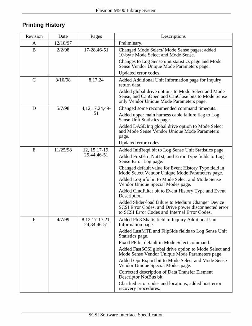
Revision Date Pages DescriptionsA 12/18/97 Preliminary.B 2/2/98 17-28,46-51 Changed Mode Select/ Mode Sense pages; added
10-byte Mode Select and Mode Sense.Changes to Log Sense unit statistics page and ModeSense Vendor Unique Mode Parameters page.Updated error codes.
C 3/10/98 8,17,24 Added Additional Unit Information page for Inquiryreturn data.Added global drive options to Mode Select and ModeSense, and CanOpen and CanClose bits to Mode Senseonly Vendor Unique Mode Parameters page.
D 5/7/98 4,12,17,24,49-51
Changed some recommended command timeouts.Added upper main harness cable failure flag to LogSense Unit Statistics page.Added DASDInq global drive option to Mode Selectand Mode Sense Vendor Unique Mode Parameterspage.Updated error codes.
E 11/25/98 12, 15,17-19,25,44,46-51
Added InitReqd bit to Log Sense Unit Statistics page.Added FirstErr, Not1st, and Error Type fields to LogSense Error Log page.Changed default value for Event History Type field inMode Select Vendor Unique Mode Parameters page.Added LogInfo bit to Mode Select and Mode SenseVendor Unique Special Modes page.Added CmdFilter bit to Event History Type and EventDescription.Added Slider-load failure to Medium Changer DeviceSCSI Error Codes, and Drive power disconnected errorto SCSI Error Codes and Internal Error Codes.
F 4/7/99 8,12,17-17,21,24,34,46-51
Added Ph 3 Shafts field to Inquiry Additional UnitInformation page.Added LastMTE and FlipSide fields to Log Sense UnitStatistics page.Fixed PF bit default in Mode Select command.Added FastSCSI global drive option to Mode Select andMode Sense Vendor Unique Mode Parameters page.Added OpnExport bit to Mode Select and Mode SenseVendor Unique Special Modes page.Corrected description of Data Transfer ElementDescriptor NotBus bit.Clarified error codes and locations; added host errorrecovery procedures.

Plasmon M500 Library System
SCSI Software Interface Specification
CONTENTS
1. Introduction................................................................................................................................................................ 1
2. Command Summary ................................................................................................................................................... 2
3. Messages, Status Bytes, and Timeouts........................................................................................................................ 3
3.1 Supported Messages .............................................................................................................................................. 3
3.2 Status Bytes ........................................................................................................................................................... 4
3.3 Recommended Command Timeouts ....................................................................................................................... 4
4. SCSI Commands ........................................................................................................................................................ 5
4.1 EXCHANGE MEDIUM Command....................................................................................................................... 5
4.2 INITIALIZE ELEMENT STATUS Command....................................................................................................... 5
4.3 INQUIRY Command............................................................................................................................................. 6
4.3.1 Supported Vital Product Data Pages Page (00h) ........................................................................................... 7
4.3.2 Unit Serial Number Page (80h)..................................................................................................................... 8
4.3.3 Additional Unit Information Page (C0h) ....................................................................................................... 8
4.4 LOG SELECT Command ...................................................................................................................................... 9
4.4.1 Unit Statistics Page (30h) ............................................................................................................................. 9
4.4.2 Error Statistics Page (31h) .......................................................................................................................... 10
4.4.3 Error Log Page (32h) .................................................................................................................................. 10
4.4.4 Event History Page (33h)............................................................................................................................ 11
4.5 LOG SENSE Command ...................................................................................................................................... 11
4.5.1 Supported Log Pages Page (00h) ................................................................................................................ 11
4.5.2 Unit Statistics Page (30h) ........................................................................................................................... 12
4.5.3 Error Statistics Page (31h) .......................................................................................................................... 14
4.5.4 Error Log Page (32h) .................................................................................................................................. 15
4.5.5 Event History Page (33h)............................................................................................................................ 16
4.6 MODE SELECT (6) Command ........................................................................................................................... 17
4.6.1 Vendor Unique Mode Parameters Page (20h).............................................................................................. 17
4.6.2 Vendor Unique Special Modes Page (21h).................................................................................................. 19
4.6.3 Drive Assignments Page (22h).................................................................................................................... 20
4.6.4 Front Panel Display Mode Page (23h) ........................................................................................................ 21
4.7 MODE SELECT (10) Command ......................................................................................................................... 21
4.8 MODE SENSE (6) Command ............................................................................................................................. 22
4.8.1 Element Address Assignment Page (1Dh) ................................................................................................... 23
4.8.2 Transport Geometry Parameters Page (1Eh)................................................................................................ 23
4.8.3 Device Capabilities Page (1Fh)................................................................................................................... 24
4.8.4 Vendor Unique Mode Parameters Page (20h).............................................................................................. 24

Plasmon M500 Library System
SCSI Software Interface Specification
4.8.5 Vendor Unique Special Modes Page (21h).................................................................................................. 25
4.8.6 Drive Assignments Page (22h).................................................................................................................... 25
4.8.7 Front Panel Display Mode Page (23h) ........................................................................................................ 26
4.8.8 Drive Layout Page (24h)............................................................................................................................. 26
4.9 MODE SENSE (10) Command ........................................................................................................................... 28
4.10 MOVE MEDIUM Command .......................................................................................................................... 29
4.11 OPEN CLOSE MAILSLOT Command........................................................................................................... 29
4.12 POSITION TO ELEMENT Command............................................................................................................ 30
4.13 PREVENT ALLOW MEDIUM REMOVAL Command................................................................................. 30
4.14 READ ELEMENT STATUS Command.......................................................................................................... 31
4.14.1 Medium Transport Element Descriptor ....................................................................................................... 32
4.14.2 Storage Element Descriptor......................................................................................................................... 33
4.14.3 Import / Export Element Descriptor ............................................................................................................ 33
4.14.4 Data Transfer Element Descriptor ............................................................................................................... 34
4.15 RELEASE Command...................................................................................................................................... 35
4.16 REQUEST SENSE Command ........................................................................................................................ 35
4.17 RESERVE Command ..................................................................................................................................... 40
4.17.1 Reserve Element List Descriptor................................................................................................................. 40
4.18 REZERO UNIT Command.............................................................................................................................. 41
4.19 SEND DIAGNOSTIC Command.................................................................................................................... 41
4.20 TEST UNIT READY Command..................................................................................................................... 42
5. Event History Type and Event Description ............................................................................................................... 44
6. Error Codes .............................................................................................................................................................. 46
6.1 Medium Changer Device SCSI Error Codes......................................................................................................... 46
6.2 Medium Changer Device Error Host Recovery Procedures................................................................................... 48
6.3 Internal Error Codes............................................................................................................................................. 49
6.4 Error Code F1h–FFh Internal Error Locations...................................................................................................... 51

Plasmon M500 Library System
SCSI Software Interface Specification, Page 1
1. Introduction
Plasmon’s M-Series is a family of optical disk based robotic library systems capable of holding a numberof optical disk drives and optical disks. The robotic device within each library system is referred to as amedium changer device and it uses the protocols and commands for medium changer devices as definedin the American National Standards Institute SCSI-2 Specification. The M-Series library system's mediumchanger device and the optical disk drives within the library system are all accessed independently.
There are a number of locations or elements within the library system which are capable of holdingoptical disk media. These consist of the import/export element, the storage elements, the mediumtransport elements, and the data transfer elements.
The Import / Export Element, or IEE, is the operator accessible slot through which optical diskcartridges are added to or removed from the library system. It is also known as the mailslot.
The Storage Elements, SE1 - SEn, are internal locations within the library system's medium store.
The Medium Transport Elements, MTE1 and MTE2, are the optical disk transport mechanisms usedto remove optical disks from or return optical disks to the import/export element, the medium store, orthe read/write optical drives.
The Data Transfer Elements, DTE1 - DTEn, are the read/write optical drives.
The following element addresses have been assigned to the M500 library system:
Element Addresses
Element Type Element AddressesSE 1 - nIEE 4001 (0FA1h)DTE 6001 - 6000+n (1771h - 1770h+n)MTE 8001, 8002 (1F41h, 1F42h)
The following SCSI-2 common commands have been implemented for the M500 medium changer device.The use of these commands is discussed in the following sections.
Inquiry Position to ElementMode Select Move MediumMode Sense Exchange MediumSend Diagnostic Open Close MailslotRezero Unit Prevent Allow Medium RemovalTest Unit Ready Initialize Element StatusRequest Sense Read Element StatusReserve Log SenseRelease Log Select
Plasmon M500 Library System
SCSI Software Interface Specification, Page 2
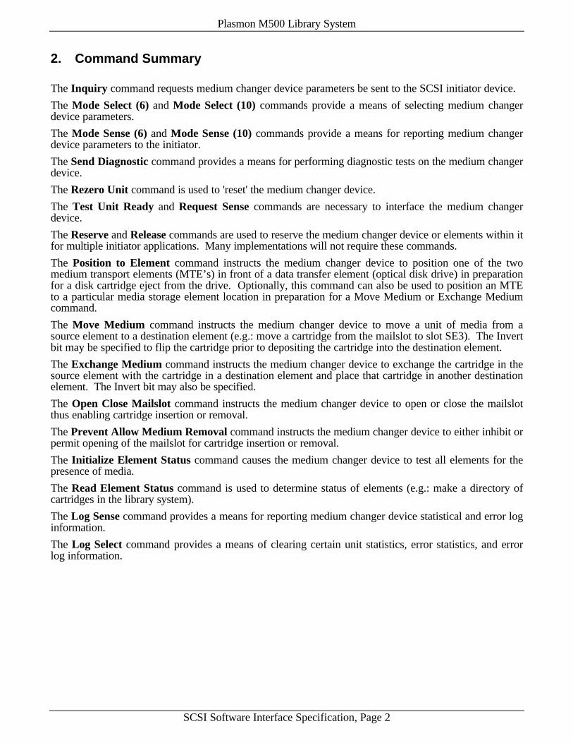
2. Command Summary
The Inquiry command requests medium changer device parameters be sent to the SCSI initiator device.
The Mode Select (6) and Mode Select (10) commands provide a means of selecting medium changerdevice parameters.
The Mode Sense (6) and Mode Sense (10) commands provide a means for reporting medium changerdevice parameters to the initiator.
The Send Diagnostic command provides a means for performing diagnostic tests on the medium changerdevice.
The Rezero Unit command is used to 'reset' the medium changer device.
The Test Unit Ready and Request Sense commands are necessary to interface the medium changerdevice.
The Reserve and Release commands are used to reserve the medium changer device or elements within itfor multiple initiator applications. Many implementations will not require these commands.
The Position to Element command instructs the medium changer device to position one of the twomedium transport elements (MTE’s) in front of a data transfer element (optical disk drive) in preparationfor a disk cartridge eject from the drive. Optionally, this command can also be used to position an MTEto a particular media storage element location in preparation for a Move Medium or Exchange Mediumcommand.
The Move Medium command instructs the medium changer device to move a unit of media from asource element to a destination element (e.g.: move a cartridge from the mailslot to slot SE3). The Invertbit may be specified to flip the cartridge prior to depositing the cartridge into the destination element.
The Exchange Medium command instructs the medium changer device to exchange the cartridge in thesource element with the cartridge in a destination element and place that cartridge in another destinationelement. The Invert bit may also be specified.
The Open Close Mailslot command instructs the medium changer device to open or close the mailslotthus enabling cartridge insertion or removal.
The Prevent Allow Medium Removal command instructs the medium changer device to either inhibit orpermit opening of the mailslot for cartridge insertion or removal.
The Initialize Element Status command causes the medium changer device to test all elements for thepresence of media.
The Read Element Status command is used to determine status of elements (e.g.: make a directory ofcartridges in the library system).
The Log Sense command provides a means for reporting medium changer device statistical and error loginformation.
The Log Select command provides a means of clearing certain unit statistics, error statistics, and errorlog information.

Plasmon M500 Library System
SCSI Software Interface Specification, Page 3
3. Messages, Status Bytes, and Timeouts
The medium changer device within the library system responds to commands as defined by and inaccordance with the ANSI X3.131-1994 specification Small Computer System Interface-2 (also knownas SCSI-2). This standard defines a protocol whereby data is transferred between two devices in asequence of phases. A request is made by sending a Command Descriptor Block (CDB) during theCOMMAND phase. For certain commands, the request is accompanied by a list of parameters sent duringthe DATA OUT phase. Some commands receive data during the DATA IN phase. This document lists thecommands and accompanying parameters for the medium changer device.
The interface to the library system is single-ended. Differential SCSI is not supported Synchronous datatransfer is not supported; neither is wide or fast data transfer. The medium changer device will neverassert the RST (Reset) line and will follow option b of section 6.1.4.2 of the ANSI X3.131-1994 SCSI-2specification if the initiator does not respond in the reselection phase.
The medium changer device will disconnect from the initiator during a Send Diagnostic, Position toElement, Move Medium, Exchange Medium, Open Close Mailslot, Initialize Element Status, or RezeroUnit command (if disconnection is supported by the initiator) thereby freeing the SCSI bus to allow otherI/O processes to occur.
3.1 Supported Messages
In the course of communication between two SCSI devices, messages are sent in the MESSAGE IN andMESSAGE OUT phases. The following messages are accepted by and sent by the medium changerdevice. The direction field indicates the direction of message transfer. The MESSAGE REJECT messageis sent for all unaccepted messages.
Message Codes
Code Message Name Direction
06h ABORT OutOCh BUS DEVICE RESET Out00h COMMAND COMPLETE In04h DISCONNECT In/Out80h+ IDENTIFY In/Out05h INITIATOR DETECTED ERROR Out09h MESSAGE PARITY ERROR Out07h MESSAGE REJECT In/Out08h NO OPERATION Out
Key: In = Target (medium changer device) to Initiator, Out = Initiator to Target (mediumchanger device)
80h+ = Codes 80h through FFh are used for IDENTIFY messages

Plasmon M500 Library System
SCSI Software Interface Specification, Page 4
3.2 Status Bytes
A status byte is sent from the medium changer device to the initiator during the STATUS phase at thetermination of each command. The supported status byte code values are listed below.
Status Byte Code
Bits of status byte Status7 6 5 4 3 2 1 0R R 0 0 0 0 0 R GOODR R 0 0 0 0 1 R CHECK CONDITIONR R 0 0 1 0 0 R BUSYR R 0 1 1 0 0 R RESERVATION CONFLICT
All other codes Not ReturnedKey: R = Reserved bit
GOOD. The medium changer device has successfully completed the command.
CHECK CONDITION. Any error, exception, or abnormal condition resulting in sense data being setcauses a CHECK CONDITION status. A Request Sense command should be issued following a CHECKCONDITION status to determine the nature of the condition.
BUSY. The medium changer device is busy and cannot accept a command.
RESERVATION CONFLICT. A command has been sent by an initiator to the medium changer devicewhen it is already reserved by another initiator.
3.3 Recommended Command Timeouts
The following values are the recommended timeout values for host software to use when issuingcommands the medium changer device. The actual command execution times depend upon the variousMode Settings in effect (see Section 4.6.1), the type of optical drives used, and the number of retriesperformed to successfully complete a command.
Suggested Timeout Values
SCSI Command TimeoutInquiry, Mode Select, Mose Sense, Request Sense, Reserve, Release, Log Select, PreventAllow Medium Removal
10 sec
Test Unit Ready, Log Sense, Read Element Status 20 secSend Diagnostic, Position to Element, Open Close Mailslot 90 secMove Medium, Exchange Medium, Rezero Unit, Initialize Element Status 5 min

Plasmon M500 Library System
SCSI Software Interface Specification, Page 5
4. SCSI Commands
4.1 EXCHANGE MEDIUM Command
The Exchange Medium command instructs the medium changer device to exchange the cartridge in thesource element with the cartridge in a destination element and place that cartridge in another destinationelement.
Bit 7 6 5 4 3 2 1 0Byte
0 Operation Code (A6h)1 Logical Unit Number (0) Reserved (0)
2 - 3 (MSB) Transport Element Address(LSB)
4 - 5 (MSB) Source Element Address(LSB)
6 - 7 (MSB) First Destination Address(LSB)
8 - 9 (MSB) Second Destination Address(LSB)
10 Reserved (0) Inv2 Inv111 Reserved (00h)
The medium in the source element is moved to the first destination element and the medium whichpreviously occupied the first destination element is moved to the second destination element.
Transport Element Address specifies the medium transport element. For the most efficient operation,an address of zero should be used. This will allow the medium changer device to use both mediumtransport elements to accomplish the cartridge exchange in the least amount of time. A specific mediumtransport element may also be specified. In this case, however, the second destination element may notbe the same as the source element
Source Element Address specifies the source element.
First Destination Address and Second Destination Address specify the two destination elements. Thefirst is the destination of the cartridge originally in the Source Element Address. The second is thedestination of the cartridge originally in the First Destination Address.
Inv1 and Inv2 specify the medium should be inverted (“flipped”) prior to being deposited in FirstDestination Address and Second Destination Address, respectively.
Note that since the first medium transport element cannot reach the import/export element in the invertedposition, and the second medium transport element cannot reach the import/export element not in theinverted position, not all combinations involving the import/export element will be permitted.
4.2 INITIALIZE ELEMENT STATUS Command
The Initialize Element Status command is used to cause the medium changer device to test all elementsfor the presence of media. The status of each element can then be read using the Read Element Statuscommand. The method by which the storage elements are checked is dependent upon the SlowScan bit inthe Mode Select command (see Section 4.6.1). Note: if the SlowScan bit is set and both mediumtransport elements are full, no statuses will be checked and the command will return an error. Otherwise,the command will proceed as normal but the empty/full status of the Optical Drives will not be checked ifboth medium transport elements are full, the ChgrEject bit in the Mode Select command is not set, or if

Plasmon M500 Library System
SCSI Software Interface Specification, Page 6
disconnects are not supported by the host. The NoScanSE and NoScanDTE bits in the Mode Selectcommand also affect which elements are checked (see Section 4.6.2).
Bit 7 6 5 4 3 2 1 0Byte
0 Operation Code (07h)1 Logical Unit Number (0) Reserved (0)
2 - 5 Reserved (00h)
4.3 INQUIRY Command
The Inquiry command is issued by the initiator to request medium changer device information.
Bit 7 6 5 4 3 2 1 0Byte
0 Operation Code (12h)1 Logical Unit Number (0) Reserved (0) EVPD2 Page Code3 Reserved (00h)4 Allocation Length5 Reserved (00h)
EVPD (Enable Vital Product Data) equals a bit of one if the vital product data page as specified by thePage Code field is to be returned or a bit of zero if standard Inquiry data is to be returned.
Page Code defines the parameter page for vital product to be returned. A value of zero, 80h, or C0hmust be used. These pages are described following the Standard Inquiry Data Format.
Allocation Length specifies how many bytes of data are to be returned.
The following page details the standard Inquiry Data Format for an Allocation Length of 45.
Standard INQUIRY Data Format
Bit 7 6 5 4 3 2 1 0Byte
0 Peripheral Qualifier (0) Peripheral Device Type (08h)1 RMB (1) Device-Type Qualifier (0)2 ISO Version (0) ECMA Version (0) ANSI-Approved Version (2)3 AENC (0) TrmIOP (0) Reserved (0) Response Data Format (2)4 Additional Length (33h)
5 - 6 Reserved (00h)7 RelAdr(0) Wbus32(0) Wbus16(0) Sync(0) Linked(0) Reserved(0) CmdQue(0) SftRe(0)
8 - 15 Vendor Identification (“IDE ”)16 - 31 Product Identification (“MULTI “)32 - 35 Product Revision Level (e.g.,”200 “)36 - 43 Manufacturer Id (“IDEMPLS.”)
44 Model Identification (‘5’)
Peripheral Qualifier equals zero indicating connection to a logical unit, or 3h indicating an invalidLogical Unit Number.

Plasmon M500 Library System
SCSI Software Interface Specification, Page 7
Peripheral Device Type equals 08h indicating a medium changer device, or 1Fh indicating an invalidLogical Unit Number.
RMB (Removable Media Bit) equals bit of one indicating medium is removable.
ANSI-Approved Version equals 2 indicating compliance with SCSI-2 Specification.
AENC (Asynchronous Event Notification) equals bit of zero indicating no support of this feature.
TrmIOP (Terminate I/O Process) equals a bit of zero indicating no support of this feature.
Response Data Format equals 2 indicating compliance with SCSI-2 Specification.
Additional Length equals 33h.
RelAdr (Relative Address) equals zero indicating no support of this feature.
WBus32 (Wide Bus - 32 bit) equals zero indicating no support of this feature.
WBus16 (Wide Bus - 16 bit) equals zero indicating no support of this feature.
Sync (Synchronous Data Transfers) equals zero indicating no support of this feature.
Linked (Linked Commands) equals zero indicating no support of this feature.
CmdQue (Command Queueing) equals zero indicating no support of this feature.
SftRe (Soft Reset) equals zero indicating the device responds to the RESET condition with the hardRESET alternative.
Vendor Identification is “IDE “.
Product Identification is “MULTI “.
Product Revision Level starts with “201 “ (2.01).
Model Identification is '5' (35h).
4.3.1 Supported Vital Product Data Pages Page (00h)
The Supported Vital Product Data Pages Page is as follows.
Bit 7 6 5 4 3 2 1 0Byte
0 Peripheral Qualifier (0) Peripheral Device Type (08h)1 Page Code (00h)2 Reserved (00h)3 Page Length (03h)4 1st Supported Page (00h)5 2nd Supported Page (80h)6 3rd Supported Page (C0h)

Plasmon M500 Library System
SCSI Software Interface Specification, Page 8
4.3.2 Unit Serial Number Page (80h)
The Unit Serial Number Page is as follows.
Bit 7 6 5 4 3 2 1 0Byte
0 Peripheral Qualifier (0) Peripheral Device Type (08h)1 Page Code (80h)2 Reserved (00h)3 Page Length (06h)
4 - 9 Product Serial Number
Product Serial Number is a six character ASCII representation of the library system's Factory SerialNumber. The least significant digit of the serial number is in byte 9.
Peripheral Qualifier and Peripheral Device Type are as in the Standard Inquiry Data Format.
4.3.3 Additional Unit Information Page (C0h)
The Additional Unit Information Page is as follows.
Bit 7 6 5 4 3 2 1 0Byte
0 Peripheral Qualifier (0) Peripheral Device Type (08h)1 Page Code (C0h)2 Reserved (00h)3 Page Length (28h)4 Library Generation (1 or 2)5 Library Development Level (2)6 Hardware Flags Ph 3 Shafts
7 - 8 (MSB) Total Number of Cartridge Slots (500)(LSB)
9 Maximum Number of Drives Supported10 Number of Library Columns (5)11 Number of Slots in Column 1 (103)12 Number of Slots in Column 2 (97)13 Number of Slots in Column 3 (98)14 Number of Slots in Column 4 (98)15 Number of Slots in Column 5 (104)
16 - 17 Reserved (00h)18 - 27 EPROM 1 Firmware Part Number (“898821-000”)28 - 37 EPROM 2 Firmware Part Number (“898822-000”)38 - 39 (MSB) EPROM 1 Firmware Checksum
(LSB)40 - 41 (MSB) EPROM 2 Firmware Checksum
(LSB)42 - 43 Reserved (00h)
Ph 3 Shafts equals a bit of one if the library is configured for phase 3 lift shafts.
Plasmon M500 Library System
SCSI Software Interface Specification, Page 9
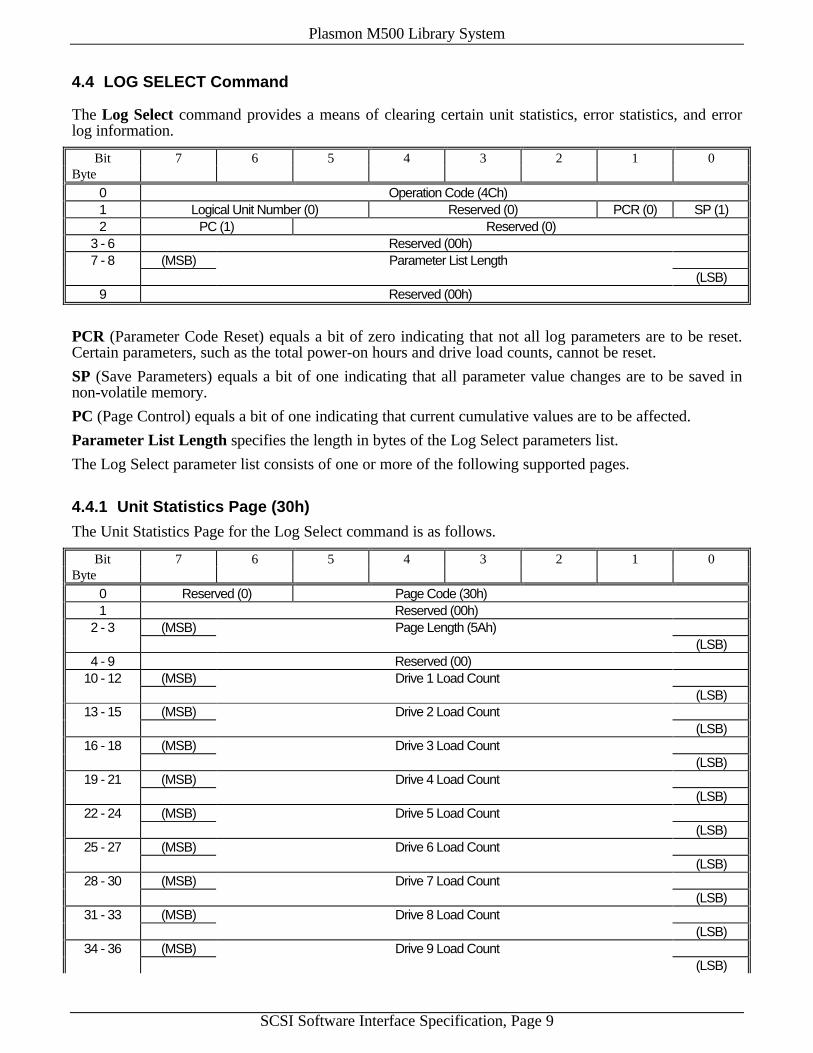
4.4 LOG SELECT Command
The Log Select command provides a means of clearing certain unit statistics, error statistics, and errorlog information.
Bit 7 6 5 4 3 2 1 0Byte
0 Operation Code (4Ch)1 Logical Unit Number (0) Reserved (0) PCR (0) SP (1)2 PC (1) Reserved (0)
3 - 6 Reserved (00h)7 - 8 (MSB) Parameter List Length
(LSB)9 Reserved (00h)
PCR (Parameter Code Reset) equals a bit of zero indicating that not all log parameters are to be reset.Certain parameters, such as the total power-on hours and drive load counts, cannot be reset.
SP (Save Parameters) equals a bit of one indicating that all parameter value changes are to be saved innon-volatile memory.
PC (Page Control) equals a bit of one indicating that current cumulative values are to be affected.
Parameter List Length specifies the length in bytes of the Log Select parameters list.
The Log Select parameter list consists of one or more of the following supported pages.
4.4.1 Unit Statistics Page (30h)
The Unit Statistics Page for the Log Select command is as follows.
Bit 7 6 5 4 3 2 1 0Byte
0 Reserved (0) Page Code (30h)1 Reserved (00h)
2 - 3 (MSB) Page Length (5Ah)(LSB)
4 - 9 Reserved (00)10 - 12 (MSB) Drive 1 Load Count
(LSB)13 - 15 (MSB) Drive 2 Load Count
(LSB)16 - 18 (MSB) Drive 3 Load Count
(LSB)19 - 21 (MSB) Drive 4 Load Count
(LSB)22 - 24 (MSB) Drive 5 Load Count
(LSB)25 - 27 (MSB) Drive 6 Load Count
(LSB)28 - 30 (MSB) Drive 7 Load Count
(LSB)31 - 33 (MSB) Drive 8 Load Count
(LSB)34 - 36 (MSB) Drive 9 Load Count
(LSB)

Plasmon M500 Library System
SCSI Software Interface Specification, Page 10
Bit 7 6 5 4 3 2 1 0Byte
37 - 39 (MSB) Drive 10 Load Count(LSB)
40 - 42 (MSB) Drive 11 Load Count(LSB)
43 - 45 (MSB) Drive 12 Load Count(LSB)
46 - 93 Reserved (00h)
If any of the Drive 1-12 Load Count fields is equal to zero, the load count of the corresponding drivewill be set to zero.
4.4.2 Error Statistics Page (31h)
The Error Statistics Page for the Log Select command is as follows.
Bit 7 6 5 4 3 2 1 0Byte
0 Reserved (0) Page Code (31h)1 Reserved (00h)
2 - 3 (MSB) Page Length (64h)(LSB)
4 - 103 Most Frequent Error Parameters (00h)
Most Frequent Error Parameters must be equal to a block of all zeros resetting all error statisticsinformation.
4.4.3 Error Log Page (32h)
The Error Log Page for the Log Select command is as follows.
Bit 7 6 5 4 3 2 1 0Byte
0 Reserved (0) Page Code (32h)1 Reserved (00h)
2 - 3 (MSB) Page Length (A0h)(LSB)
4 - 163 Most Recent Error Parameters
Most Recent Error Parameters must be equal to a block of all zeros resetting all error log information.

Plasmon M500 Library System
SCSI Software Interface Specification, Page 11
4.4.4 Event History Page (33h)
The Event History Page for the Log Select command is as follows.
Bit 7 6 5 4 3 2 1 0Byte
0 Reserved Page Code (33h)1 Reserved (00h)
2 - 3 (MSB) Page Length (02h)(LSB)
4 - 5 (MSB) Number of Events Recorded (00h)(LSB)
Number of Events Recorded must equal zero clearing all event history information.
4.5 LOG SENSE Command
The Log Sense command provides a means for reporting medium changer device statistical and error loginformation.
Bit 7 6 5 4 3 2 1 0Byte
0 Operation Code (4Dh)1 Logical Unit Number (0) Reserved (0) PPC (0) SP (0)2 PC (1) Page Code
3 - 6 Reserved (00h)7 - 8 (MSB) Allocation Length
(LSB)9 Reserved (00h)
Page Code defines the parameter page to be returned. A value of zero, 30h, 31h, 32h, or 33h must beused. The corresponding page as described below is returned.
Allocation Length specifies how many bytes of data are to be returned.
4.5.1 Supported Log Pages Page (00h)
The Supported Log Pages Page is as follows.
Bit 7 6 5 4 3 2 1 0Byte
0 Reserved (0) Page Code (00h)1 Reserved (00h)
2 - 3 (MSB) Page Length (05h)(LSB)
4 1st Supported Page (00h)5 2nd Supported Page (30h)6 3rd Supported Page (31h)7 4th Supported Page (32h)8 5th Supported Page (33h)

Plasmon M500 Library System
SCSI Software Interface Specification, Page 12
4.5.2 Unit Statistics Page (30h)
The Unit Statistics Page for the Log Sense command is as follows.
Bit 7 6 5 4 3 2 1 0Byte
0 Reserved (0) Page Code (30h)1 Reserved (00h)
2 - 3 (MSB) Page Length (5Ah)(LSB)
4 - 6 (MSB) Total Power-On Hours(LSB)
7 - 9 (MSB) Cumulative Cycle Count(LSB)
10 - 12 (MSB) Drive 1 Load Count(LSB)
13 - 15 (MSB) Drive 2 Load Count(LSB)
16 - 18 (MSB) Drive 3 Load Count(LSB)
19 - 21 (MSB) Drive 4 Load Count(LSB)
22 - 24 (MSB) Drive 5 Load Count(LSB)
25 - 27 (MSB) Drive 6 Load Count(LSB)
28 - 30 (MSB) Drive 7 Load Count(LSB)
31 - 33 (MSB) Drive 8 Load Count(LSB)
34 - 36 (MSB) Drive 9 Load Count(LSB)
37 - 39 (MSB) Drive 10 Load Count(LSB)
40 - 42 (MSB) Drive 11 Load Count(LSB)
43 - 45 (MSB) Drive 12 Load Count(LSB)
46 OverTemp Rsvd(0) MainHUpr TermPwr PivotCable MainHLwr LiftCable DoorOpen47 Reserved(0) Drv I/F1 Disc Drv 6 Disc Drv 5 Disc Drv 4 Disc Drv 3 Disc Drv 2 Disc Drv 1 Disc48 Reserved(0) Drv I/F2 Disc Drv 12 Disc Drv 11 Disc Drv 10 Disc Drv 9 Disc Drv 8 Disc Drv 7 Disc49 InitReqd LastMTE FlipSide Low Pwr 4 Low Pwr 3 Low Pwr 2 Low Pwr 1
50 - 53 (MSB) Cumulative Lift Movement Count(LSB)
54 - 57 (MSB) Cumulative Slider Movement Count - Slider 1(LSB)
58 - 61 (MSB) Cumulative Slider Movement Count - Slider 2(LSB)
62 - 65 (MSB) Cumulative Change of Slider in Use Count(LSB)
66 - 69 (MSB) Cumulative Pivot Movement Count(LSB)
70 - 73 (MSB) Cumulative Mailslot Open Count(LSB)
Plasmon M500 Library System
SCSI Software Interface Specification, Page 13
Bit 7 6 5 4 3 2 1 0Byte
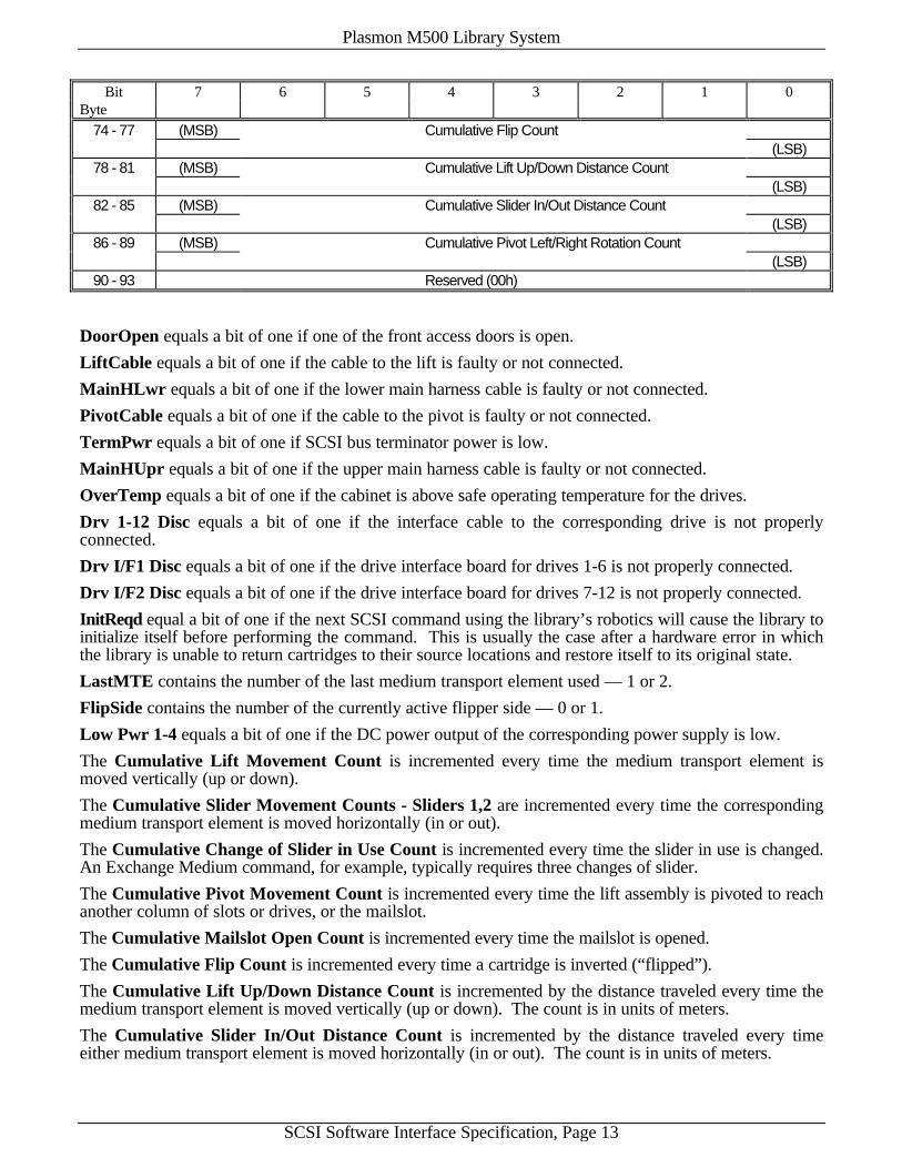
74 - 77 (MSB) Cumulative Flip Count(LSB)
78 - 81 (MSB) Cumulative Lift Up/Down Distance Count(LSB)
82 - 85 (MSB) Cumulative Slider In/Out Distance Count(LSB)
86 - 89 (MSB) Cumulative Pivot Left/Right Rotation Count(LSB)
90 - 93 Reserved (00h)
DoorOpen equals a bit of one if one of the front access doors is open.
LiftCable equals a bit of one if the cable to the lift is faulty or not connected.
MainHLwr equals a bit of one if the lower main harness cable is faulty or not connected.
PivotCable equals a bit of one if the cable to the pivot is faulty or not connected.
TermPwr equals a bit of one if SCSI bus terminator power is low.
MainHUpr equals a bit of one if the upper main harness cable is faulty or not connected.
OverTemp equals a bit of one if the cabinet is above safe operating temperature for the drives.
Drv 1-12 Disc equals a bit of one if the interface cable to the corresponding drive is not properlyconnected.
Drv I/F1 Disc equals a bit of one if the drive interface board for drives 1-6 is not properly connected.
Drv I/F2 Disc equals a bit of one if the drive interface board for drives 7-12 is not properly connected.
InitReqd equal a bit of one if the next SCSI command using the library’s robotics will cause the library toinitialize itself before performing the command. This is usually the case after a hardware error in whichthe library is unable to return cartridges to their source locations and restore itself to its original state.
LastMTE contains the number of the last medium transport element used — 1 or 2.
FlipSide contains the number of the currently active flipper side — 0 or 1.
Low Pwr 1-4 equals a bit of one if the DC power output of the corresponding power supply is low.
The Cumulative Lift Movement Count is incremented every time the medium transport element ismoved vertically (up or down).
The Cumulative Slider Movement Counts - Sliders 1,2 are incremented every time the correspondingmedium transport element is moved horizontally (in or out).
The Cumulative Change of Slider in Use Count is incremented every time the slider in use is changed.An Exchange Medium command, for example, typically requires three changes of slider.
The Cumulative Pivot Movement Count is incremented every time the lift assembly is pivoted to reachanother column of slots or drives, or the mailslot.
The Cumulative Mailslot Open Count is incremented every time the mailslot is opened.
The Cumulative Flip Count is incremented every time a cartridge is inverted (“flipped”).
The Cumulative Lift Up/Down Distance Count is incremented by the distance traveled every time themedium transport element is moved vertically (up or down). The count is in units of meters.
The Cumulative Slider In/Out Distance Count is incremented by the distance traveled every timeeither medium transport element is moved horizontally (in or out). The count is in units of meters.
Plasmon M500 Library System
SCSI Software Interface Specification, Page 14
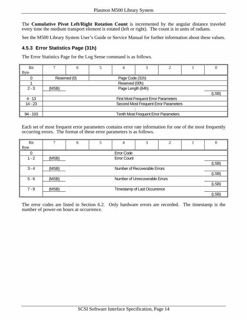
The Cumulative Pivot Left/Right Rotation Count is incremented by the angular distance traveledevery time the medium transport element is rotated (left or right). The count is in units of radians.
See the M500 Library System User’s Guide or Service Manual for further information about these values.
4.5.3 Error Statistics Page (31h)
The Error Statistics Page for the Log Sense command is as follows.
Bit 7 6 5 4 3 2 1 0Byte
0 Reserved (0) Page Code (31h)1 Reserved (00h)
2 - 3 (MSB) Page Length (64h)(LSB)
4 - 13 First Most Frequent Error Parameters14 - 23 Second Most Frequent Error Parameters
:94 - 103 Tenth Most Frequent Error Parameters
Each set of most frequent error parameters contains error rate information for one of the most frequentlyoccurring errors. The format of these error parameters is as follows.
Bit 7 6 5 4 3 2 1 0Byte
0 Error Code1 - 2 (MSB) Error Count
(LSB)3 - 4 (MSB) Number of Recoverable Errors
(LSB)5 - 6 (MSB) Number of Unrecoverable Errors
(LSB)7 - 9 (MSB) Timestamp of Last Occurrence
(LSB)
The error codes are listed in Section 6.2. Only hardware errors are recorded. The timestamp is thenumber of power-on hours at occurrence.
Plasmon M500 Library System
SCSI Software Interface Specification, Page 15
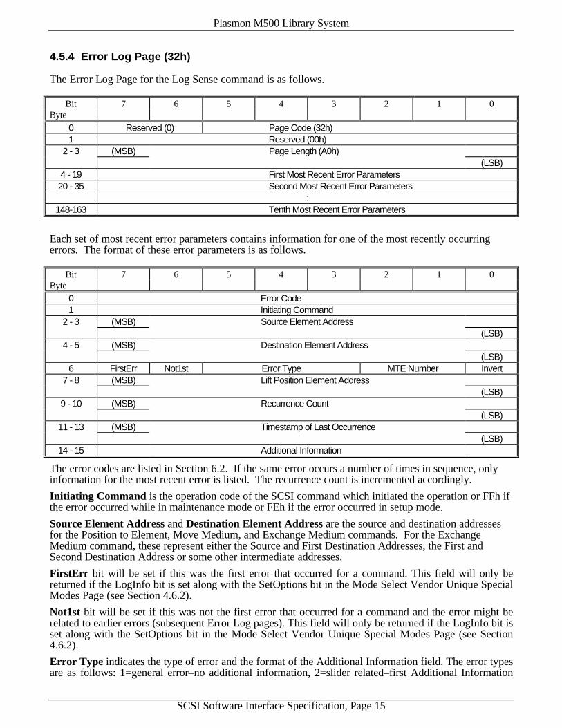
4.5.4 Error Log Page (32h)
The Error Log Page for the Log Sense command is as follows.
Bit 7 6 5 4 3 2 1 0Byte
0 Reserved (0) Page Code (32h)1 Reserved (00h)
2 - 3 (MSB) Page Length (A0h)(LSB)
4 - 19 First Most Recent Error Parameters20 - 35 Second Most Recent Error Parameters
:148-163 Tenth Most Recent Error Parameters
Each set of most recent error parameters contains information for one of the most recently occurringerrors. The format of these error parameters is as follows.
Bit 7 6 5 4 3 2 1 0Byte
0 Error Code1 Initiating Command
2 - 3 (MSB) Source Element Address(LSB)
4 - 5 (MSB) Destination Element Address(LSB)
6 FirstErr Not1st Error Type MTE Number Invert7 - 8 (MSB) Lift Position Element Address
(LSB)9 - 10 (MSB) Recurrence Count
(LSB)11 - 13 (MSB) Timestamp of Last Occurrence
(LSB)14 - 15 Additional Information
The error codes are listed in Section 6.2. If the same error occurs a number of times in sequence, onlyinformation for the most recent error is listed. The recurrence count is incremented accordingly.
Initiating Command is the operation code of the SCSI command which initiated the operation or FFh ifthe error occurred while in maintenance mode or FEh if the error occurred in setup mode.
Source Element Address and Destination Element Address are the source and destination addressesfor the Position to Element, Move Medium, and Exchange Medium commands. For the ExchangeMedium command, these represent either the Source and First Destination Addresses, the First andSecond Destination Address or some other intermediate addresses.
FirstErr bit will be set if this was the first error that occurred for a command. This field will only bereturned if the LogInfo bit is set along with the SetOptions bit in the Mode Select Vendor Unique SpecialModes Page (see Section 4.6.2).
Not1st bit will be set if this was not the first error that occurred for a command and the error might berelated to earlier errors (subsequent Error Log pages). This field will only be returned if the LogInfo bit isset along with the SetOptions bit in the Mode Select Vendor Unique Special Modes Page (see Section4.6.2).
Error Type indicates the type of error and the format of the Additional Information field. The error typesare as follows: 1=general error–no additional information, 2=slider related–first Additional Information

Plasmon M500 Library System
SCSI Software Interface Specification, Page 16
byte contains the slider number, 3=column related–first Additional Information byte contains the columnnumber, 4=drive related–first Additional Information byte contains the drive number, 5=drive SCSIrelated–first Additional Information bytes contain an ASC/ASCQ or an error code of F1h-FFh and a low-level SCSI error location, 6=power supply related–first Additional Information byte contains the powersupply number, or 7=drive control board related–first Additional Information byte contains the drivecontrol board number. This field will only be returned if the LogInfo bit is set along with the SetOptionsbit in the Mode Select Vendor Unique Special Modes Page (see Section 4.6.2).
MTE Number is the number of the medium transport element (1 or 2) in use when the error occurred.
Invert equals a bit of one for the Move Medium and Exchange Medium commands if the medium was tobe inverted (“flipped”) prior to being deposited in the destination element.
Lift Position Element Address is the address of the element at which the medium transport elementspecified by the Medium Transport Element Number was positioned when the error occurred.
Recurrence Count is a count of the number of consecutive times that the error occurred, includingretries, with all other information being identical between instances. The total of these identical instancesis recorded as one log entry.
Additional Information contains such information as the value of ASC and ASCQ received from thedrive in the event of an eject failure when the ChgrEject mode of operation is enabled or the drive notbecoming ready when the WaitLoad mode of operation is enabled (see the Mode Select command), orother errors as indicated by ErrorType above. For low-level SCSI errors (error codes F1h and greater)the first byte contains the error number and the second byte contains the low-level SCSI error location.The error codes are listed in Section 6.2 and the error locations are listed in Section 6.4.
4.5.5 Event History Page (33h)
The Event History Page for the Log Sense command is as follows.
Bit 7 6 5 4 3 2 1 0Byte
0 Reserved (0) Page Code (33h)1 Reserved (00h)
2 - 3 (MSB) Page Length (0802h)(LSB)
4 - 5 (MSB) Number of Events Recorded(LSB)
6 - 2053 Event List
Number of Events Recorded is the number of significant bytes in the Event List.
Event List is a list of events from most recent to least recent within the library system. The contents ofthis list is determined by the Event History Type field of the Vendor Unique Modes Parameters Page ofthe Mode Select command (see Section 4.6.1). For a description of possible events within this list seeSection 5. This list may be helpful to technical support personnel in diagnosing problems with the librarysystem.

Plasmon M500 Library System
SCSI Software Interface Specification, Page 17
4.6 MODE SELECT (6) Command
The Mode Select (6) command provides a means for the initiator to select medium changer deviceparameters.
Bit 7 6 5 4 3 2 1 0Byte
0 Operation Code (15h)1 Logical Unit Number (0) PF (1) Reserved (0) SP
2 - 3 Reserved (00h)4 Parameter List Length5 Reserved (00h)
PF (Page Format) equals a bit of one indicating that parameters are structured as pages of relatedparameters.
SP (Save Pages) equals a bit of one if the target is to save changeable parameters in pages, i.e., if valuesare to be saved to non-volatile memory. If this bit is zero, values are not saved when power is cycled tothe library or when it receives a Bus Device Reset message or the SCSI Reset line is asserted.
Parameter List Length specifies the length in bytes of the Mode Select (6) parameter list.
The Mode Select (6) parameter list consists of a 4 byte header followed by one or more of the mediumchanger device's supported pages. The header is shown below followed by the supported pages.
Mode Select (6) Mode Parameter Header
Bit 7 6 5 4 3 2 1 0Byte
0 Mode Data Length (00h)1 Medium Type (00h)2 Device-Specific Parameter (00h)3 Block Descriptor Length (00h)
4.6.1 Vendor Unique Mode Parameters Page (20h)
The Mode Select Vendor Unique Mode Parameters Page is as follows.
Bit 7 6 5 4 3 2 1 0Byte
0 Reserved (0) Page Code (20h)1 Parameter Length (08h)2 ReportRec SlowScans LimitRec ChgrEject Rsvd (0) WaitLoad IgnParity Park3 Reserved (0) SetDr1-6 Loaded Drive Number4 SetNBus Reserved (0) SetDr7-12 Rsvd (0) Number of Buses5 Reserved (00h)6 SetDrOpt Reserved (0) FastSCSI DASDInq FVerOnWr WrCaEnab7 Reserved (00h)8 SetType Reserved (0)9 Event History Type
ReportRec equals a bit of one if the medium changer device is to return CHECK CONDITION status andset Request Sense data for all recoverable hardware errors, or zero if the device is to return GOOD status

Plasmon M500 Library System
SCSI Software Interface Specification, Page 18
for all recoverable hardware errors. If this bit is set and a recoverable error occurs on a subsequentcommand, then the Request Sense sense key will be set to RECOVERED ERROR and the ASC and ASCQfields will be set accordingly. The default for this bit is zero.
SlowScans equals a bit of one if the medium changer device is to use tactile feedback rather than retro-reflective sensors to sense the empty/full status of storage elements for the Initialize Element Statuscommand. Setting this bit may be necessary depending upon the type of media used. As an example,some cartridge shells may be difficult to detect with sensors due to variations in color and reflectivity.Setting this bit slows down the element scan appreciably. The default for this bit is zero.
LimitRec equals a bit of one if the medium changer device is to limit the extent of the error recovery thatit will perform. Setting this bit will prevent the changer from performing any transfers on a cartridge thatcannot be moved to a destination element or returned to its original source element. Rather than placingthe cartridge in its original storage element, the import/export element, or in a drive, it will be left in the amedium transport element. The host software is then responsible for moving the cartridge from thiselement. Setting this bit also prevents the Rezero Unit command from unloading all drives. The defaultfor this bit is zero.
ChgrEject equals a bit of one if the medium changer device is to eject a cartridge from an optical drive inresponse to a Move Medium or Exchange Medium command with the drive specified as the SourceElement (or First Destination). If this bit is not set then the host software is responsible for ejecting thecartridge from the optical drive before the Move Medium or Exchange Medium command is issued.Setting this bit will also cause the Rezero Unit command to unload all drives before moving the changerdevice to its home position, unless the LmtErrRec bit is set as described above. If the medium transportelement is not currently positioned at the drive, a signal will be sent to spin down the drive beforepositioning to it, thus improving overall cartridge exchange performance. The default for this bit is one.
WaitLoad equals a bit of one if the medium changer device is to wait for a Ready response from anoptical drive in response to a Move Medium or Exchange Medium command with the drive specified asthe Destination Element (or Second Destination). Command completion status is not returned to the hostuntil the host is ready, or 35 seconds have elapsed. After 35 seconds, drive power is cycled in an attemptto reseat the cartridge. If this bit is not set then the host is responsible for waiting until the cartridge isspun up and ready. The default for this bit is zero.
IgnParity equals a bit of one if parity is to be ignored. This is non-standard for SCSI-2 but may berequired for some initiators. The default for this bit is zero.
Park equals a bit of one if the Media Transport Element is to be moved to its park position on the nextRezero Unit command issued. This is required in preparation for shipment of the system. The default forthis bit is zero.
SetDr1-6 and SetDr7-12 equal a bit of one if an optical drive is to be set to the loaded or unloaded statein the medium changer device's non-volatile memory. Use SetDr1-6 for drives 1 to 6 and SetDr7-12 fordrives 7 to 12. Setting these bits is generally unnecessary as non-volatile memory is updatedautomatically whenever a drive is loaded or unloaded. The Initialize Element Status command can alsobe used to update the empty/full status of the optical drives.
Loaded equals a bit of one if the corresponding optical drives are to be set to the loaded state or zero ifthey are to be set to the unloaded state. The SetDrive bit must also be set.
Drive Number is a code for the number of the drive to be set to the loaded or unloaded state. Fordrives 1 to 6, set SetDr1-6 above and use the values 1 to 6 in this field. For drives 7 to 12, set SetDr7-12above and use the values 1 to 6 in this field (1 for drive 7, 2 for drive 8, etc.)
SetNBus equals a bit of one if the Number of Buses is to be set or a bit of zero if it is to remainunchanged.
Number of Buses specifies the number of SCSI buses for which the library system is to be configured.The following values may be used: 1, 2, or 4. If a value of 1 is used, the medium changer device andoptical drives (up to 6 drives) are assumed to reside on a single SCSI bus. If a value of 2 is used, themedium changer and drives 1 - 3 are assumed to reside on one SCSI bus, and drives 4 - 6 are assumed toreside on a separate SCSI bus. If a value of 4 is used, the medium changer device is assumed to reside on
Plasmon M500 Library System
SCSI Software Interface Specification, Page 19
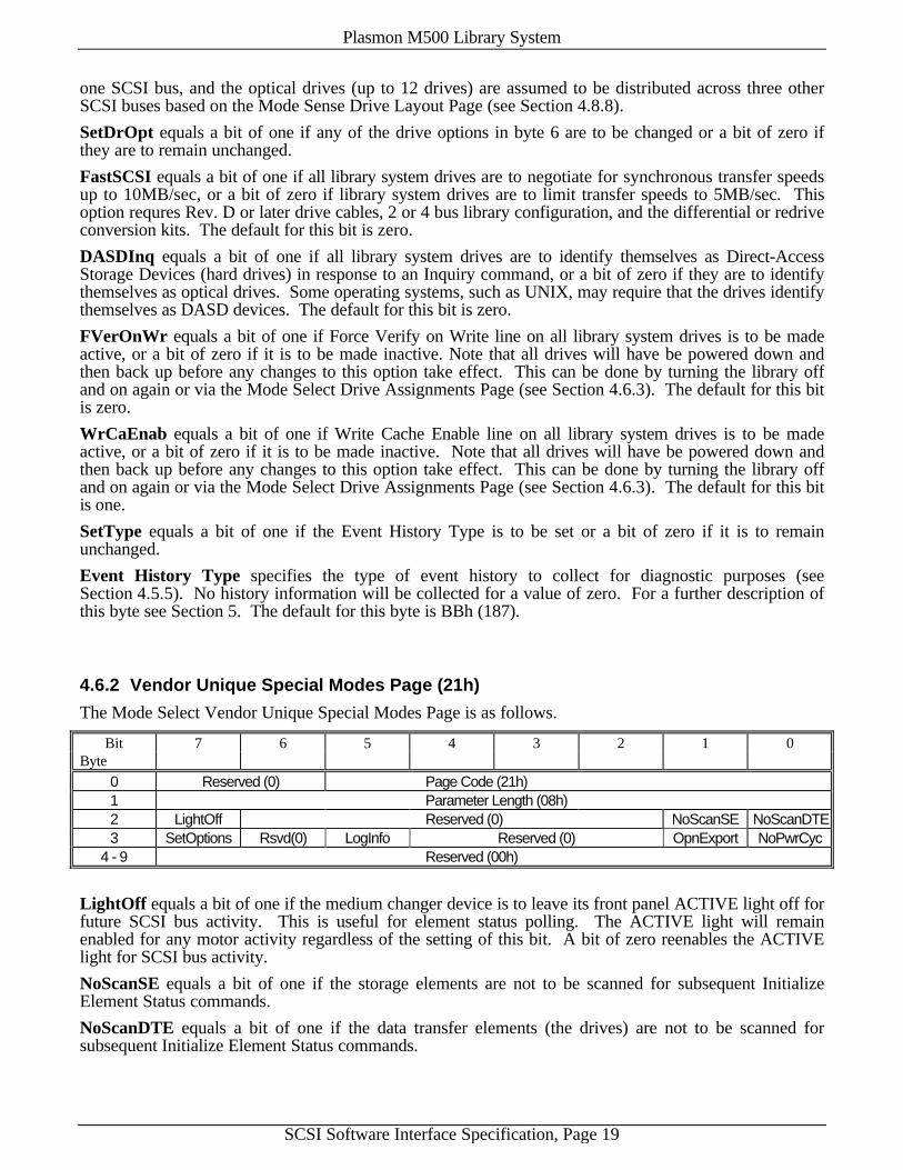
one SCSI bus, and the optical drives (up to 12 drives) are assumed to be distributed across three otherSCSI buses based on the Mode Sense Drive Layout Page (see Section 4.8.8).
SetDrOpt equals a bit of one if any of the drive options in byte 6 are to be changed or a bit of zero ifthey are to remain unchanged.
FastSCSI equals a bit of one if all library system drives are to negotiate for synchronous transfer speedsup to 10MB/sec, or a bit of zero if library system drives are to limit transfer speeds to 5MB/sec. Thisoption requres Rev. D or later drive cables, 2 or 4 bus library configuration, and the differential or redriveconversion kits. The default for this bit is zero.
DASDInq equals a bit of one if all library system drives are to identify themselves as Direct-AccessStorage Devices (hard drives) in response to an Inquiry command, or a bit of zero if they are to identifythemselves as optical drives. Some operating systems, such as UNIX, may require that the drives identifythemselves as DASD devices. The default for this bit is zero.
FVerOnWr equals a bit of one if Force Verify on Write line on all library system drives is to be madeactive, or a bit of zero if it is to be made inactive. Note that all drives will have be powered down andthen back up before any changes to this option take effect. This can be done by turning the library offand on again or via the Mode Select Drive Assignments Page (see Section 4.6.3). The default for this bitis zero.
WrCaEnab equals a bit of one if Write Cache Enable line on all library system drives is to be madeactive, or a bit of zero if it is to be made inactive. Note that all drives will have be powered down andthen back up before any changes to this option take effect. This can be done by turning the library offand on again or via the Mode Select Drive Assignments Page (see Section 4.6.3). The default for this bitis one.
SetType equals a bit of one if the Event History Type is to be set or a bit of zero if it is to remainunchanged.
Event History Type specifies the type of event history to collect for diagnostic purposes (seeSection 4.5.5). No history information will be collected for a value of zero. For a further description ofthis byte see Section 5. The default for this byte is BBh (187).
4.6.2 Vendor Unique Special Modes Page (21h)
The Mode Select Vendor Unique Special Modes Page is as follows.
Bit 7 6 5 4 3 2 1 0Byte
0 Reserved (0) Page Code (21h)1 Parameter Length (08h)2 LightOff Reserved (0) NoScanSE NoScanDTE3 SetOptions Rsvd(0) LogInfo Reserved (0) OpnExport NoPwrCyc
4 - 9 Reserved (00h)
LightOff equals a bit of one if the medium changer device is to leave its front panel ACTIVE light off forfuture SCSI bus activity. This is useful for element status polling. The ACTIVE light will remainenabled for any motor activity regardless of the setting of this bit. A bit of zero reenables the ACTIVElight for SCSI bus activity.
NoScanSE equals a bit of one if the storage elements are not to be scanned for subsequent InitializeElement Status commands.
NoScanDTE equals a bit of one if the data transfer elements (the drives) are not to be scanned forsubsequent Initialize Element Status commands.

Plasmon M500 Library System
SCSI Software Interface Specification, Page 20
SetOptions equals a bit of one if any of the options in byte 3 are to be changed or a bit of zero if they areto remain unchanged.
LogInfo equals a bit of one if the Log Sense command is to return additional information in the ErrorLog Page (see Section 4.4.3). The SetOptions bit must also be set for this bit to be effective.
OpnExport equals a bit of one if the mailslot is to be opened when a cartridge is moved to it, or a bit ofzero if the mailslot is to remain closed. The SetOptions bit must also be set for this bit to be effective.The default for this bit is zero.
NoPwrCyc equals a bit of one if the AC power to the optical drives is not to be cycled as part of thenormal error recovery procedure or a bit of zero if the AC power is to be cycled in an attempt to reseat abadly seated cartridge. The SetOptions bit must also be set for this bit to be effective. Setting this bitreduces the ability of the library system to recover from drive load failures.
4.6.3 Drive Assignments Page (22h)
The Mode Select Drive Assignments Page is as follows.
Bit 7 6 5 4 3 2 1 0Byte
0 Reserved (0) Page Code (22h)1 Parameter Length (1Ah)2 Drive 1 On-Line3 Drive 1 SCSI ID4 Drive 2 On-Line5 Drive 2 SCSI ID6 Drive 3 On-Line7 Drive 3 SCSI ID8 Drive 4 On-Line9 Drive 4 SCSI ID10 Drive 5 On-Line11 Drive 5 SCSI ID12 Drive 6 On-Line13 Drive 6 SCSI ID14 Drive 7 On-Line15 Drive 7 SCSI ID16 Drive 8 On-Line17 Drive 8 SCSI ID18 Drive 9 On-Line19 Drive 9 SCSI ID20 Drive 10 On-Line21 Drive 10 SCSI ID22 Drive 11 On-Line23 Drive 11 SCSI ID24 Drive 12 On-Line25 Drive 12 SCSI ID
26 - 27 Reserved (00h)
Drive 1-12 On-Line are the on-line designators for the drives in the library system. If set to zero, thecorresponding drive will be powered down and considered off-line. If set to a non-zero value, thecorresponding drive will be powered up and considered on-line. This provides a means of takingmalfunctioning drives off-line and reinstating them to on-line status, if so desired. If a drive is to bedisconnected for replacement (hot-swapped), all drives on the same bus should be taken off-line. Thiscan be done with one command. Any attempt to position to an off-line drive will be considered an error.
Plasmon M500 Library System
SCSI Software Interface Specification, Page 21
Drive 1-12 SCSI ID are the SCSI ID's of the optical drives in the library system. Changing these valueschanges the address of the drives on the SCSI bus on which they are located. The drives correspondingto the altered SCSI ID’s will be automatically powered down and back up again to effect the change ofaddress. SCSI ID’s should be unique for drives on the same SCSI bus. The SCSI ID field is only used ifthe drive is on-line (powered up).
4.6.4 Front Panel Display Mode Page (23h)
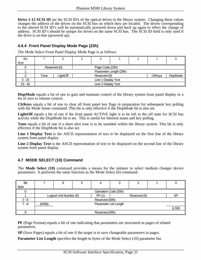
The Mode Select Front Panel Display Mode Page is as follows.
Bit 7 6 5 4 3 2 1 0Byte
0 Reserved (0) Page Code (23h)1 Parameter Length (29h)2 Tone LightOff Reserved (0) ClrKeys DispMode
3 - 22 Line 1 Display Text23 - 42 Line 2 Display Text
DispMode equals a bit of one to gain and maintain control of the library system front panel display or abit of zero to release control.
ClrKeys equals a bit of one to clear all front panel key flags in preparation for subsequent key pollingwith the Mode Sense command. This bit is only effective if the DispMode bit is also set.
LightOff equals a bit of one if the front panel ACTIVE light is to be left in the off state for SCSI busactivity while the DispMode bit is set. This is useful for element status and key polling.
Tone equals a bit of one if a short alert tone is to be sounded within the library system. This bit is onlyeffective if the DispMode bit is also set.
Line 1 Display Text is the ASCII representation of text to be displayed on the first line of the librarysystem front panel display.
Line 2 Display Text is the ASCII representation of text to be displayed on the second line of the librarysystem front panel display.
4.7 MODE SELECT (10) Command
The Mode Select (10) command provides a means for the initiator to select medium changer deviceparameters. It performs the same function as the Mode Select (6) command.
Bit 7 6 5 4 3 2 1 0Byte
0 Operation Code (55h)1 Logical Unit Number (0) PF (1) Reserved (0) SP
2 - 6 Reserved (00h)7 - 8 (MSB) Parameter List Length
(LSB)9 Reserved (00h)
PF (Page Format) equals a bit of one indicating that parameters are structured as pages of relatedparameters.
SP (Save Pages) equals a bit of one if the target is to save changeable parameters in pages.
Parameter List Length specifies the length in bytes of the Mode Select (10) parameter list.

Plasmon M500 Library System
SCSI Software Interface Specification, Page 22
The Mode Select (10) parameter list consists of a 8 byte header followed by one or more of the mediumchanger device's supported pages. The header is shown below.
Mode Select (10) Mode Parameter Header
Bit 7 6 5 4 3 2 1 0Byte
0 - 1 Mode Data Length (00h)2 Medium Type (00h)3 Device-Specific Parameter (00h)
4 - 5 Reserved (00h)6 - 7 Block Descriptor Length (00h)
See the Mode Select (6) command (Section 4.6) for information about supported mode pages.
4.8 MODE SENSE (6) Command
The Mode Sense (6) command provides a means for reporting medium changer device to an initiator.
Bit 7 6 5 4 3 2 1 0Byte
0 Operation Code (1Ah)1 Logical Unit Number (0) Rsvd (0) DBD (0) Reserved (0)2 PC Page Code3 Reserved (00h)4 Allocation Length5 Reserved (00h)
DBD (Disable Block Descriptor) is ignored.
PC (Page Control) defines the type of parameter values to be returned. Normally, a value of zero is usedto return the current values.
Page Code defines the parameter page(s) to be returned. A value of zero, 1Dh, 1Eh, 1Fh, 20h, 21h, 22h,23h, 24h, or 3Fh must be used. If a value of zero is used, no pages are returned. If a value of 1Dh, 1Eh,1Fh, 20h, 21h, 22h, 23h, or 24h is used, the corresponding page as described below is returned. If avalue of 3Fh is used, all supported pages are returned.
The Allocation Length specifies how many bytes of data are to be returned.
The Mode Sense (6) data block consists of a 4 byte header followed by one or more supported pages.The header is shown below followed by the supported pages.
Mode Sense (6) Mode Parameter Header
Bit 7 6 5 4 3 2 1 0Byte
0 Mode Data Length1 Medium Type (00h)2 Device-Specific Parameter (00h)3 Block Descriptor Length (00h)
Mode Data Length is the length in bytes of the remainder of the Mode Sense (6) return data.
Plasmon M500 Library System
SCSI Software Interface Specification, Page 23
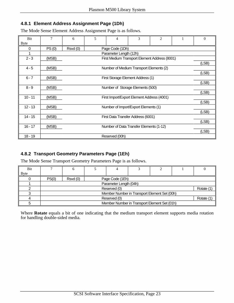
4.8.1 Element Address Assignment Page (1Dh)
The Mode Sense Element Address Assignment Page is as follows.
Bit 7 6 5 4 3 2 1 0Byte
0 PS (0) Rsvd (0) Page Code (1Dh)1 Parameter Length (12h)
2 - 3 (MSB) First Medium Transport Element Address (8001)(LSB)
4 - 5 (MSB) Number of Medium Transport Elements (2)(LSB)
6 - 7 (MSB) First Storage Element Address (1)(LSB)
8 - 9 (MSB) Number of Storage Elements (500)(LSB)
10 - 11 (MSB) First Import/Export Element Address (4001)(LSB)
12 - 13 (MSB) Number of Import/Export Elements (1)(LSB)
14 - 15 (MSB) First Data Transfer Address (6001)(LSB)
16 - 17 (MSB) Number of Data Transfer Elements (1-12)(LSB)
18 - 19 Reserved (00h)
4.8.2 Transport Geometry Parameters Page (1Eh)
The Mode Sense Transport Geometry Parameters Page is as follows.
Bit 7 6 5 4 3 2 1 0Byte
0 PS(0) Rsvd (0) Page Code (1Eh)1 Parameter Length (04h)2 Reserved (0) Rotate (1)3 Member Number in Transport Element Set (00h)4 Reserved (0) Rotate (1)5 Member Number in Transport Element Set (01h)
Where Rotate equals a bit of one indicating that the medium transport element supports media rotationfor handling double-sided media.
Plasmon M500 Library System
SCSI Software Interface Specification, Page 24
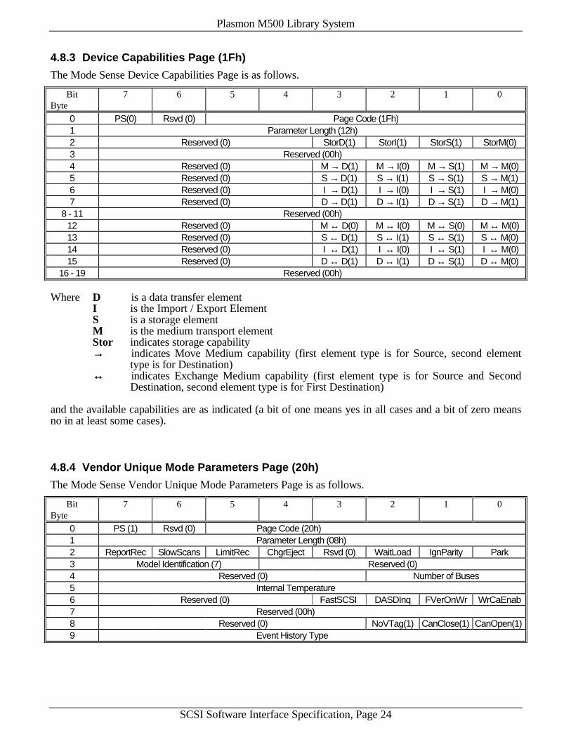
4.8.3 Device Capabilities Page (1Fh)
The Mode Sense Device Capabilities Page is as follows.
Bit 7 6 5 4 3 2 1 0Byte
0 PS(0) Rsvd (0) Page Code (1Fh)1 Parameter Length (12h)2 Reserved (0) StorD(1) StorI(1) StorS(1) StorM(0)3 Reserved (00h)4 Reserved (0) M → D(1) M → I(0) M → S(1) M → M(0)5 Reserved (0) S → D(1) S → I(1) S → S(1) S → M(1)6 Reserved (0) I → D(1) I → I(0) I → S(1) I → M(0)7 Reserved (0) D → D(1) D → I(1) D → S(1) D → M(1)
8 - 11 Reserved (00h)12 Reserved (0) M ↔ D(0) M ↔ I(0) M ↔ S(0) M ↔ M(0)13 Reserved (0) S ↔ D(1) S ↔ I(1) S ↔ S(1) S ↔ M(0)14 Reserved (0) I ↔ D(1) I ↔ I(0) I ↔ S(1) I ↔ M(0)15 Reserved (0) D ↔ D(1) D ↔ I(1) D ↔ S(1) D ↔ M(0)
16 - 19 Reserved (00h)
Where D is a data transfer elementI is the Import / Export ElementS is a storage elementM is the medium transport elementStor indicates storage capability→→ indicates Move Medium capability (first element type is for Source, second element
type is for Destination)↔↔ indicates Exchange Medium capability (first element type is for Source and Second
Destination, second element type is for First Destination)
and the available capabilities are as indicated (a bit of one means yes in all cases and a bit of zero meansno in at least some cases).
4.8.4 Vendor Unique Mode Parameters Page (20h)
The Mode Sense Vendor Unique Mode Parameters Page is as follows.
Bit 7 6 5 4 3 2 1 0Byte
0 PS (1) Rsvd (0) Page Code (20h)1 Parameter Length (08h)2 ReportRec SlowScans LimitRec ChgrEject Rsvd (0) WaitLoad IgnParity Park3 Model Identification (7) Reserved (0)4 Reserved (0) Number of Buses5 Internal Temperature6 Reserved (0) FastSCSI DASDInq FVerOnWr WrCaEnab7 Reserved (00h)8 Reserved (0) NoVTag(1) CanClose(1) CanOpen(1)9 Event History Type

Plasmon M500 Library System
SCSI Software Interface Specification, Page 25
ReportRec, SlowScans, LimitRec, ChgrEject, WaitLoad, IgnParity, Park, Number of Buses,FastSCSI, DASDInq, FVerOnWr, WrCaEnab, and Event History Type are as set by the ModeSelect command.
Model Identification equals 7 for the M500.
Internal Temperature equals the internal library system temperature at the rear of the drives. The valueis in degrees Celsius.
CanOpen equals a bit of one indicating that the library supports mailslot opening via the Open CloseMailslot command. This bit can be used to distinguish this capability of the M500 from other olderPlasmon libraries which do not support this feature.
CanClose equals a bit of one indicating that the library supports mailslot closure via the Open CloseMailslot command. This bit can be used to distinguish this capability of the M500 from other M-Seriesand older Plasmon libraries which do not support this feature.
NoVTag equals a bit of one indicating that the library does not support volume tags. This bit can be usedto distinguish this inability of the M500 from other M-Series and older Plasmon libraries which dosupport volume tags.
4.8.5 Vendor Unique Special Modes Page (21h)
The Mode Sense Vendor Unique Special Modes Page is as follows.
Bit 7 6 5 4 3 2 1 0Byte
0 PS (1) Rsvd (0) Page Code (21h)1 Parameter Length (08h)2 LightOff Reserved (0) NoScanSE NoScanDTE3 Reserved (0) LogInfo Reserved (0) OpnExport NoPwrCyc
4 - 9 Reserved (00h)
LightOff, NoScanSE, NoScanDTE, LogInfo, OpnExport, and NoPwrCyc are as set by the ModeSelect command.
4.8.6 Drive Assignments Page (22h)
The Mode Sense Drive Assignments Page is as follows.
Bit 7 6 5 4 3 2 1 0Byte
0 PS (1) Rsvd (0) Page Code (22h)1 Parameter Length (1Ah)2 Drive 1 Type3 Drive 1 SCSI ID4 Drive 2 Type5 Drive 2 SCSI ID6 Drive 3 Type7 Drive 3 SCSI ID8 Drive 4 Type9 Drive 4 SCSI ID10 Drive 5 Type11 Drive 5 SCSI ID12 Drive 6 Type13 Drive 6 SCSI ID14 Drive 7 Type

Plasmon M500 Library System
SCSI Software Interface Specification, Page 26
Bit 7 6 5 4 3 2 1 0Byte
15 Drive 7 SCSI ID16 Drive 8 Type17 Drive 8 SCSI ID18 Drive 9 Type19 Drive 9 SCSI ID20 Drive 10 Type21 Drive 10 SCSI ID22 Drive 11 Type23 Drive 11 SCSI ID24 Drive 12 Type25 Drive 12 SCSI ID
26 - 27 Reserved (00h)
Drive 1-12 Type are the drive type designators for the optical drives in the library system. If a drive isoff-line (powered-off), it’s Drive Type will be zero.
Drive 1-12 SCSI ID are the SCSI ID's of the optical drives in the library system. If a drive is off-line(powered down), its SCSI ID will not be used until the drive is brought back on-line (powered up).
4.8.7 Front Panel Display Mode Page (23h)
The Mode Sense Front Panel Display Mode Page is as follows.
Bit 7 6 5 4 3 2 1 0Byte
0 PS (0) Rsvd (0) Page Code (23h)1 Parameter Length (29h)2 Rsvd (0) LightOff Rsvd (0) Key Pressed Rsvd (0) DispMode
3 - 42 Reserved (00h)
LightOff and DispMode are as set by the Mode Select command.
Key Pressed equals zero if no key was pressed or one of the following:
1 First (left-most) key was pressed2 Second key was pressed3 Third key was pressed4 Fourth (right-most) key was pressed
The Key Pressed field is cleared every time that this page is returned so that each Mode Sense commandreturns key presses since the last Mode Sense command was issued.
4.8.8 Drive Layout Page (24h)
The Mode Sense Drive Layout Page is as follows.
Bit 7 6 5 4 3 2 1 0Byte
0 PS (0) Rsvd (0) Page Code (24h)1 Parameter Length (19h)2 Drive 1 Tower (2) Drive 1 Vertical Position (2)

Plasmon M500 Library System
SCSI Software Interface Specification, Page 27
Bit 7 6 5 4 3 2 1 0Byte
3 Drive 1 SCSI Bus (1 for single bus, 1 for dual bus, or 2 for quad bus)4 Drive 2 Tower (2) Drive 2 Vertical Position (1)5 Drive 2 SCSI Bus (1 for single bus, 1 for dual bus, or 2 for quad bus)6 Drive 3 Tower (3) Drive 3 Vertical Position (2)7 Drive 3 SCSI Bus (1 for single bus, 1 for dual bus, or 3 for quad bus)8 Drive 4 Tower (3) Drive 4 Vertical Position (1)9 Drive 4 SCSI Bus (1 for single bus, 2 for dual bus, or 3 for quad bus)10 Drive 5 Tower (4) Drive 5 Vertical Position (2)11 Drive 5 SCSI Bus (1 for single bus, 2 for dual bus, or 4 for quad bus)12 Drive 6 Tower (4) Drive 6 Vertical Position (1)13 Drive 6 SCSI Bus (1 for single bus, 2 for dual bus, or 4 for quad bus)14 Drive 7 Tower (2) Drive 7 Vertical Position (3)15 Drive 7 SCSI Bus (0=N/A for single bus, 0=N/A for dual bus, or 2 for quad bus)16 Drive 8 Tower (3) Drive 8 Vertical Position (3)17 Drive 8 SCSI Bus (0=N/A for single bus, 0=N/A for dual bus, or 3 for quad bus)18 Drive 9 Tower (4) Drive 9 Vertical Position (3)19 Drive 9 SCSI Bus (0=N/A for single bus, 0=N/A for dual bus, or 4 for quad bus)20 Drive 10 Tower (2) Drive 10 Vertical Position (4)21 Drive 10 SCSI Bus (0=N/A for single bus, 0=N/A for dual bus, or 2 for quad bus)22 Drive 11 Tower (3) Drive 11 Vertical Position (4)23 Drive 11 SCSI Bus (0=N/A for single bus, 0=N/A for dual bus, or 3 for quad bus)24 Drive 12 Tower (4) Drive 12 Vertical Position (4)25 Drive 12 SCSI Bus (0=N/A for single bus, 0=N/A for dual bus, or 4 for quad bus)26 Reserved (00h)
Drive 1-12 Tower are the library system tower numbers (from 1 to 5) for the drives in the library system.The drives occupy the center three towers in the library system. The first library system tower containsthe first storage element, SE1.
Drive 1-12 Vertical Position are vertical positions of the corresponding drives in each tower withposition 1 corresponding to the lowest drive position within the tower.
Drive 1-12 SCSI Bus are the internal library SCSI bus numbers for the drives in the library system. Notethat this number depends upon whether the library system is configured for one, two, or four internalSCSI buses. Refer to the Number of Buses field in the Mode Select Vendor Unique Mode ParametersPage (Section 4.6.1).

Plasmon M500 Library System
SCSI Software Interface Specification, Page 28
4.9 MODE SENSE (10) Command
The Mode Sense (10) command provides a means for reporting medium changer device to an initiator.It performs the same function as the Mode Sense (6) command.
Bit 7 6 5 4 3 2 1 0Byte
0 Operation Code (5Ah)1 Logical Unit Number (0) Rsvd (0) DBD (0) Reserved (0)2 PC Page Code
3 - 6 Reserved (00h)7 - 8 (MSB) Allocation Length
(LSB)9 Reserved (00h)
DBD (Disable Block Descriptor) is ignored.
PC (Page Control) defines the type of parameter values to be returned. Normally, a value of zero is usedto return the current values.
Page Code defines the parameter page(s) to be returned.
The Allocation Length specifies how many bytes of data are to be returned.
The Mode Sense (10) data block consists of a 8 byte header followed by one or more supported pages.The header is shown below.
Mode Sense (10) Mode Parameter Header
Bit 7 6 5 4 3 2 1 0Byte
0 - 1 (MSB) Mode Data Length(LSB)
2 Medium Type (00h)3 Device-Specific Parameter (00h)
4 - 5 Reserved (00h)6 - 7 Block Descriptor Length (00h)
Mode Data Length is the length in bytes of the remainder of the Mode Sense (10) return data.
See the Mose Sense (6) command (Section 4.8) for information about supported mode pages.

Plasmon M500 Library System
SCSI Software Interface Specification, Page 29
4.10 MOVE MEDIUM Command
The Move Medium command instructs the medium changer device move a unit of media from a sourceelement to a destination element.
Bit 7 6 5 4 3 2 1 0Byte
0 Operation Code (A5h)1 Logical Unit Number (0) Reserved (0)
2 - 3 (MSB) Transport Element Address(LSB)
4 - 5 (MSB) Source Element Address(LSB)
6 - 7 (MSB) Destination Address(LSB)
8 - 9 Reserved (00h)10 Reserved (0) Invert11 Reserved (00h)
Transport Element Address specifies the medium transport element. A value of zero should normallybe used. This will move the cartridge using the first medium transport element. The address of a specificmedium transport element may also be used.
Source Element Address specifies the source element.
Destination Address specifies the destination element.
Invert specifies the medium should be inverted. If the Invert bit is one, the media is inverted (“flipped”)prior to being deposited into the destination element.
Note that since the first medium transport element cannot reach the import/export element in the invertedposition, and the second medium transport element cannot reach the import/export element not in theinverted position, not all combinations involving the import/export element will be permitted.
4.11 OPEN CLOSE MAILSLOT Command
The Open Close Mailslot command instructs the medium changer device to open the import/export slot(the mailslot) thus enabling cartridge insertion or removal, or to close the slot thus disabling cartridgeinsertion and removal. This command has no effect if the changer has been placed in the Prevent state bythe Prevent Allow Medium Removal command.
Bit 7 6 5 4 3 2 1 0Byte
0 Operation Code (0Ch)1 Logical Unit Number (0) Reserved (0)
2 - 3 Reserved (00h)4 Reserved (0) Open5 Reserved (00h)
Open equals a bit of one if the medium changer device is to open rather than close the mailslot.
Plasmon M500 Library System
SCSI Software Interface Specification, Page 30
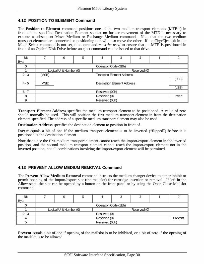
4.12 POSITION TO ELEMENT Command
The Position to Element command positions one of the two medium transport elements (MTE’s) infront of the specified Destination Element so that no further movement of the MTE is necessary toexecute a subsequent Move Medium or Exchange Medium command. Note that the two mediumtransport elements are connected so positioning one will also move the other. If the ChgrEject bit in theMode Select command is not set, this command must be used to ensure that an MTE is positioned infront of an Optical Disk Drive before an eject command can be issued to that drive.
Bit 7 6 5 4 3 2 1 0Byte
0 Operation Code (2Bh)1 Logical Unit Number (0) Reserved (0)
2 - 3 (MSB) Transport Element Address(LSB)
4 - 5 (MSB) Destination Element Address(LSB)
6 - 7 Reserved (00h)8 Reserved (0) Invert9 Reserved (00h)
Transport Element Address specifies the medium transport element to be positioned. A value of zeroshould normally be used. This will position the first medium transport element in front the destinationelement specified. The address of a specific medium transport element may also be used.
Destination Address specifies the destination element to position in front of.
Invert equals a bit of one if the medium transport element is to be inverted (“flipped”) before it ispositioned at the destination element.
Note that since the first medium transport element cannot reach the import/export element in the invertedposition, and the second medium transport element cannot reach the import/export element not in theinverted position, not all combinations involving the import/export element will be permitted.
4.13 PREVENT ALLOW MEDIUM REMOVAL Command
The Prevent Allow Medium Removal command instructs the medium changer device to either inhibit orpermit opening of the import/export slot (the mailslot) for cartridge insertion or removal. If left in theAllow state, the slot can be opened by a button on the front panel or by using the Open Close Mailslotcommand.
Bit 7 6 5 4 3 2 1 0Byte
0 Operation Code (1Eh)1 Logical Unit Number (0) Reserved (0)
2 - 3 Reserved (0)4 Reserved (0) Prevent5 Reserved (00h)
Prevent equals a bit of one if opening of the mailslot is to be inhibited, or a bit of zero if the opening ofthe mailslot is to be allowed

Plasmon M500 Library System
SCSI Software Interface Specification, Page 31
4.14 READ ELEMENT STATUS Command
The Read Element Status command requests the medium changer device report the status of its internalelements to the initiator.
Bit 7 6 5 4 3 2 1 0Byte
0 Operation Code (B8h)1 Logical Unit Number (0) VolTag (0) Element Type Code
2 - 3 (MSB) Starting Element Address(LSB)
4 - 5 (MSB) Number of Elements(LSB)
6 Reserved (00h)7 - 9 (MSB) Allocation Length
(LSB)10 - 11 Reserved (00h)
VolTag (Volume Tag) equals bit of zero since the medium changer device does not support volume tags.
Element Type Code specifies an element type as follows:
0 All element types1 Medium transport element2 Storage element3 Import/export element4 Data transfer element
Starting Element Address specifies the minimum element address to report. Only elements with anelement type permitted by the Element Type Code and the Starting Element Address are reported.
Number of Elements specifies the maximum number of element descriptor tags to be reported by themedium changer device for this command. The value specified by this field is not the range of elementaddresses to be considered for reporting but rather the number of elements to report.
Allocation Length specifies the length of the Element Status Data.
The structure of the Element Status Data returned is as follows:
Element Status Data8 byte header + Element Status PagesElement Status Page
8 byte header + Element DescriptorsElement Descriptor
:Element Descriptor
Element Status Page(More Element Descriptors)
(More Element Status Pages)
Bytes counted inpage header
Bytes counted inoverall header
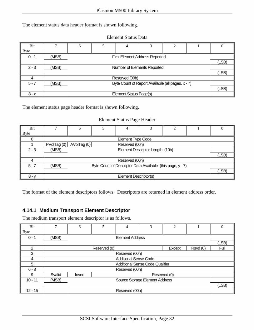
Plasmon M500 Library System
SCSI Software Interface Specification, Page 32
The element status data header format is shown following.
Element Status Data
Bit 7 6 5 4 3 2 1 0Byte
0 - 1 (MSB) First Element Address Reported(LSB)
2 - 3 (MSB) Number of Elements Reported(LSB)
4 Reserved (00h)5 - 7 (MSB) Byte Count of Report Available (all pages, x - 7)
(LSB)8 - x Element Status Page(s)
The element status page header format is shown following.
Element Status Page Header
Bit 7 6 5 4 3 2 1 0Byte
0 Element Type Code1 PVolTag (0) AVolTag (0) Reserved (00h)
2 - 3 (MSB) Element Descriptor Length (10h)(LSB)
4 Reserved (00h)5 - 7 (MSB) Byte Count of Descriptor Data Available (this page, y - 7)
(LSB)8 - y Element Descriptor(s)
The format of the element descriptors follows. Descriptors are returned in element address order.
4.14.1 Medium Transport Element Descriptor
The medium transport element descriptor is as follows.
Bit 7 6 5 4 3 2 1 0Byte
0 - 1 (MSB) Element Address(LSB)
2 Reserved (0) Except Rsvd (0) Full3 Reserved (00h)4 Additional Sense Code5 Additional Sense Code Qualifier
6 - 8 Reserved (00h)9 Svalid Invert Reserved (0)
10 - 11 (MSB) Source Storage Element Address(LSB)
12 - 15 Reserved (00h)

Plasmon M500 Library System
SCSI Software Interface Specification, Page 33
Except equals a bit of one if the element is in an abnormal state. In this case, additional information isgiven in the Additional Sense Code and in the Additional Sense Code Qualifier fields.
Full equals a bit of one if the element contains a unit of media.
Additional Sense Code and Additional Sense Code Qualifier indicate detailed information related to anon-recoverable error condition. These error codes are listed in Section 6.1.
SValid (Storage Element Valid) equals bit of one if Source Storage Element Address and Invert bit arevalid.
Invert equals a bit of one if the unit of media now in this element was inverted by Move Mediumoperation since it was last in the Source Storage Element Address.
Source Storage Element Address provides the address of the last storage element this unit of media wasmoved from.
4.14.2 Storage Element Descriptor
The storage element descriptor is as follows.
Bit 7 6 5 4 3 2 1 0Byte
0 - 1 (MSB) Element Address(LSB)
2 Reserved (0) Access Except Rsvd (0) Full3 Reserved (00h)4 Additional Sense Code5 Additional Sense Code Qualifier
6 - 8 Reserved (00h)9 Svalid Invert Reserved (0)
10 - 11 (MSB) Source Storage Element Address(LSB)
12 - 15 Reserved (00h)
Access equals a bit of one if element access by the medium transport element is allowed.
Other fields are the same as for the medium transport element descriptor.
4.14.3 Import / Export Element Descriptor
The import/export element descriptor is as follows.
Bit 7 6 5 4 3 2 1 0Byte
0 - 1 (MSB) Element Address(LSB)
2 Reserved (0) InEnab(1) ExEnab(1) Access Except ImpExp Full3 Reserved (00h)4 Additional Sense Code5 Additional Sense Code Qualifier
6 - 8 Reserved (00h)9 Svalid Invert Reserved (0)
10 - 11 (MSB) Source Storage Element Address(LSB)
12 - 15 Reserved (00h)
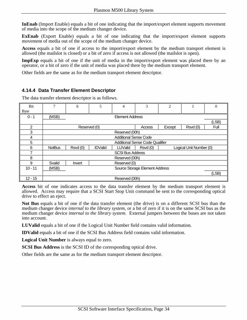
Plasmon M500 Library System
SCSI Software Interface Specification, Page 34
InEnab (Import Enable) equals a bit of one indicating that the import/export element supports movementof media into the scope of the medium changer device.
ExEnab (Export Enable) equals a bit of one indicating that the import/export element supportsmovement of media out of the scope of the medium changer device.
Access equals a bit of one if access to the import/export element by the medium transport element isallowed (the mailslot is closed) or a bit of zero if access is not allowed (the mailslot is open).
ImpExp equals a bit of one if the unit of media in the import/export element was placed there by anoperator, or a bit of zero if the unit of media was placed there by the medium transport element.
Other fields are the same as for the medium transport element descriptor.
4.14.4 Data Transfer Element Descriptor
The data transfer element descriptor is as follows.
Bit 7 6 5 4 3 2 1 0Byte
0 - 1 (MSB) Element Address(LSB)
2 Reserved (0) Access Except Rsvd (0) Full3 Reserved (00h)4 Additional Sense Code5 Additional Sense Code Qualifier6 NotBus Rsvd (0) IDValid LUValid Rsvd (0) Logical Unit Number (0)7 SCSI Bus Address8 Reserved (00h)9 Svalid Invert Reserved (0)
10 - 11 (MSB) Source Storage Element Address(LSB)
12 - 15 Reserved (00h)
Access bit of one indicates access to the data transfer element by the medium transport element isallowed. Access may require that a SCSI Start Stop Unit command be sent to the corresponding opticaldrive to effect an eject.
Not Bus equals a bit of one if the data transfer element (the drive) is on a different SCSI bus than themedium changer device internal to the library system, or a bit of zero if it is on the same SCSI bus as themedium changer device internal to the library system. External jumpers between the buses are not takeninto account.
LUValid equals a bit of one if the Logical Unit Number field contains valid information.
IDValid equals a bit of one if the SCSI Bus Address field contains valid information.
Logical Unit Number is always equal to zero.
SCSI Bus Address is the SCSI ID of the corresponding optical drive.
Other fields are the same as for the medium transport element descriptor.

Plasmon M500 Library System
SCSI Software Interface Specification, Page 35
4.15 RELEASE Command
The Release command is used to release a previously reserved medium changer device or previouslyreserved elements within it.
Bit 7 6 5 4 3 2 1 0Byte
0 Operation Code (17h)1 Logical Unit Number (0) 3rdPty Third Party Device ID Element2 Reservation Identification
3 - 5 Reserved (00h)
Element equals bit of one if a specific set of elements is to be released or a bit of zero if the entiremedium changer device is to be released.
3rdPty equals a bit of one if a reservation made using the 3rdPty option of the Reserve command is to bereleased.
Third Party Device ID is the SCSI ID of the initiator for whom the reservation was made if the 3rdPtybit is set.
Reservation Identification is a code byte used to identify a specific element reservation to be released.
4.16 REQUEST SENSE Command
The Request Sense command requests that the medium changer device send Sense Data to the initiator.
Bit 7 6 5 4 3 2 1 0Byte
0 Operation Code (03h)1 Logical Unit Number (0) Reserved (0)
2 - 3 Reserved (00h)4 Allocation Length5 Reserved (00h)
The Sense Data will be valid for a CHECK CONDITION status returned on the prior command. TheSense Data will be preserved by the medium changer device until retrieved by the Request Sensecommand or until receipt of any other command.
The Request Sense command shall return a CHECK CONDITION status only to report fatal errors for theRequest Sense command. For example:
1) The medium changer device detects a non-zero reserve bit in the CDB.2) An unrecoverable parity error occurred on the DATA BUS.3) An medium changer device malfunction prevents return of the sense data.
Any nonfatal error occurring during the execution of the Request Sense command shall return the sensedata with GOOD status.
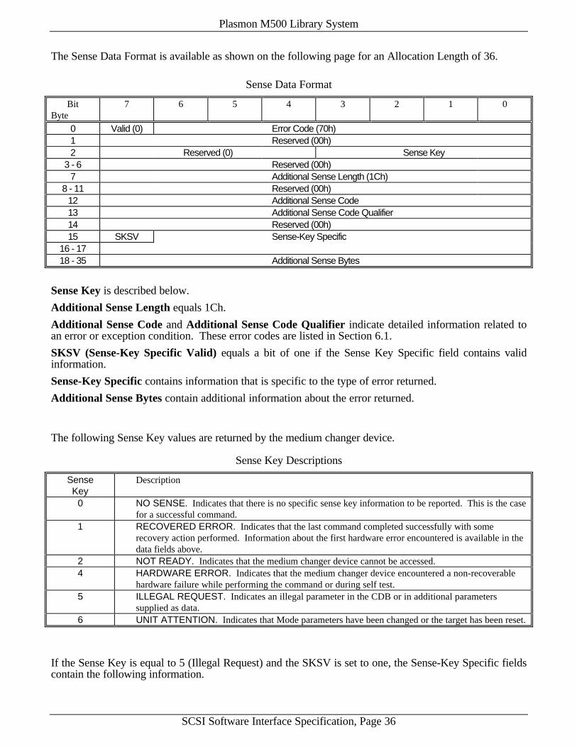
Plasmon M500 Library System
SCSI Software Interface Specification, Page 36
The Sense Data Format is available as shown on the following page for an Allocation Length of 36.
Sense Data Format
Bit 7 6 5 4 3 2 1 0Byte
0 Valid (0) Error Code (70h)1 Reserved (00h)2 Reserved (0) Sense Key
3 - 6 Reserved (00h)7 Additional Sense Length (1Ch)
8 - 11 Reserved (00h)12 Additional Sense Code13 Additional Sense Code Qualifier14 Reserved (00h)15 SKSV Sense-Key Specific
16 - 1718 - 35 Additional Sense Bytes
Sense Key is described below.
Additional Sense Length equals 1Ch.
Additional Sense Code and Additional Sense Code Qualifier indicate detailed information related toan error or exception condition. These error codes are listed in Section 6.1.
SKSV (Sense-Key Specific Valid) equals a bit of one if the Sense Key Specific field contains validinformation.
Sense-Key Specific contains information that is specific to the type of error returned.
Additional Sense Bytes contain additional information about the error returned.
The following Sense Key values are returned by the medium changer device.
Sense Key Descriptions
Sense DescriptionKey
0 NO SENSE. Indicates that there is no specific sense key information to be reported. This is the casefor a successful command.
1 RECOVERED ERROR. Indicates that the last command completed successfully with somerecovery action performed. Information about the first hardware error encountered is available in thedata fields above.
2 NOT READY. Indicates that the medium changer device cannot be accessed.4 HARDWARE ERROR. Indicates that the medium changer device encountered a non-recoverable
hardware failure while performing the command or during self test.5 ILLEGAL REQUEST. Indicates an illegal parameter in the CDB or in additional parameters
supplied as data.6 UNIT ATTENTION. Indicates that Mode parameters have been changed or the target has been reset.
If the Sense Key is equal to 5 (Illegal Request) and the SKSV is set to one, the Sense-Key Specific fieldscontain the following information.
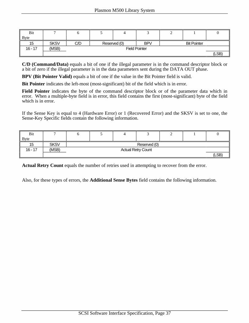
Plasmon M500 Library System
SCSI Software Interface Specification, Page 37
Bit 7 6 5 4 3 2 1 0Byte
15 SKSV C/D Reserved (0) BPV Bit Pointer16 - 17 (MSB) Field Pointer
(LSB)
C/D (Command/Data) equals a bit of one if the illegal parameter is in the command descriptor block ora bit of zero if the illegal parameter is in the data parameters sent during the DATA OUT phase.
BPV (Bit Pointer Valid) equals a bit of one if the value in the Bit Pointer field is valid.
Bit Pointer indicates the left-most (most-significant) bit of the field which is in error.
Field Pointer indicates the byte of the command descriptor block or of the parameter data which inerror. When a multiple-byte field is in error, this field contains the first (most-significant) byte of the fieldwhich is in error.
If the Sense Key is equal to 4 (Hardware Error) or 1 (Recovered Error) and the SKSV is set to one, theSense-Key Specific fields contain the following information.
Bit 7 6 5 4 3 2 1 0Byte
15 SKSV Reserved (0)16 - 17 (MSB) Actual Retry Count
(LSB)
Actual Retry Count equals the number of retries used in attempting to recover from the error.
Also, for these types of errors, the Additional Sense Bytes field contains the following information.
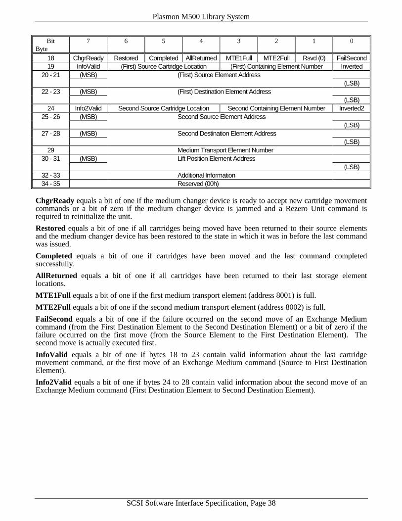
Plasmon M500 Library System
SCSI Software Interface Specification, Page 38
Bit 7 6 5 4 3 2 1 0Byte
18 ChgrReady Restored Completed AllReturned MTE1Full MTE2Full Rsvd (0) FailSecond19 InfoValid (First) Source Cartridge Location (First) Containing Element Number Inverted
20 - 21 (MSB) (First) Source Element Address(LSB)
22 - 23 (MSB) (First) Destination Element Address(LSB)
24 Info2Valid Second Source Cartridge Location Second Containing Element Number Inverted225 - 26 (MSB) Second Source Element Address
(LSB)27 - 28 (MSB) Second Destination Element Address
(LSB)29 Medium Transport Element Number
30 - 31 (MSB) Lift Position Element Address(LSB)
32 - 33 Additional Information34 - 35 Reserved (00h)
ChgrReady equals a bit of one if the medium changer device is ready to accept new cartridge movementcommands or a bit of zero if the medium changer device is jammed and a Rezero Unit command isrequired to reinitialize the unit.
Restored equals a bit of one if all cartridges being moved have been returned to their source elementsand the medium changer device has been restored to the state in which it was in before the last commandwas issued.
Completed equals a bit of one if cartridges have been moved and the last command completedsuccessfully.
AllReturned equals a bit of one if all cartridges have been returned to their last storage elementlocations.
MTE1Full equals a bit of one if the first medium transport element (address 8001) is full.
MTE2Full equals a bit of one if the second medium transport element (address 8002) is full.
FailSecond equals a bit of one if the failure occurred on the second move of an Exchange Mediumcommand (from the First Destination Element to the Second Destination Element) or a bit of zero if thefailure occurred on the first move (from the Source Element to the First Destination Element). Thesecond move is actually executed first.
InfoValid equals a bit of one if bytes 18 to 23 contain valid information about the last cartridgemovement command, or the first move of an Exchange Medium command (Source to First DestinationElement).
Info2Valid equals a bit of one if bytes 24 to 28 contain valid information about the second move of anExchange Medium command (First Destination Element to Second Destination Element).
Plasmon M500 Library System
SCSI Software Interface Specification, Page 39
(First) Source Cartridge Location and Second Source Cartridge Location contain values indicatingthe final location of the cartridges in the first and second source elements, respectively. (The secondsource element is the First Destination Element of an Exchange Medium command.) These values are asfollows:
1 Cartridge is in source element2 Cartridge is in medium transport element (if not the source or destination element) where the
MTE is specified by the (First) Containing Element Number or Second Containing ElementNumber fields (1 for MTE1 or 2 for MTE2)
3 Cartridge is in destination element4 Cartridge is in its last occupied storage element (if not the source or destination element)5 Cartridge has been lost6 Cartridge is in import/export element (if not the source or destination element)7 Cartridge is in data transfer element 1 to 6 (if not the source or destination element) where the
DTE is specified by the (First) Containing Element Number or Second Containing ElementNumber fields (1 for DTE1, 2 for DTE2, etc.)
0 Cartridge is in data transfer element 7 to 12 (if not the source or destination element) where theDTE is specified by the (First) Containing Element Number or Second Containing ElementNumber fields (1 for DTE7, 2 for DTE8, etc.)
(First) Containing Element Number and Second Containing Element Number are the numbers ofthe elements containing the cartridges originally in the first and second source elements, respectively, ifthe corresponding Source Cartridge Location fields contain the numbers 2 or 7, starting with 1 forMTE1, and 1 for DTE1 (optical drive 1) or DTE7 (optical drive 7).
Inverted and Inverted2 equal bits of one if the cartridges originally in the first and second sourceelements, respectively, are now inverted from their original states.
(First) Source Element and (First) Destination Element are the addresses of Source and DestinationElements of the last cartridge movement command, or the Source and First Destination Elements of thelast Exchange Medium command.
Second Source Element and Second Destination Element are the addresses of First and SecondDestination Elements of the last Exchange Medium command.
Medium Transport Element Number is the number of the medium transport element (1 or 2) in usewhen the error occurred.
Lift Position Element Address is the address of the element at which the medium transport elementspecified by the medium transport element Number field was positioned when the error occurred.
Additional Information contains such information as the value of ASC and ASCQ received from thedrive in the event of an eject failure when the ChgrEject mode of operation is enabled or the drive notbecoming ready when the WaitLoad mode of operation is enabled (see Section 4.6.1).
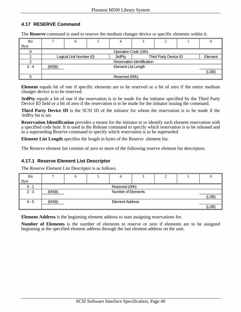
Plasmon M500 Library System
SCSI Software Interface Specification, Page 40
4.17 RESERVE Command
The Reserve command is used to reserve the medium changer device or specific elements within it.
Bit 7 6 5 4 3 2 1 0Byte
0 Operation Code (16h)1 Logical Unit Number (0) 3rdPty Third Party Device ID Element2 Reservation Identification
3 - 4 (MSB) Element List Length(LSB)
5 Reserved (00h)
Element equals bit of one if specific elements are to be reserved or a bit of zero if the entire mediumchanger device is to be reserved.
3rdPty equals a bit of one if the reservation is to be made for the initiator specified by the Third PartyDevice ID field or a bit of zero if the reservation is to be made for the initiator issuing the command.
Third Party Device ID is the SCSI ID of the initiator for whom the reservation is to be made if the3rdPty bit is set.
Reservation Identification provides a means for the initiator to to identify each element reservation witha specified code byte. It is used in the Release command to specify which reservation is to be released andin a superseding Reserve command to specify which reservation is to be superseded
Element List Length specifies the length in bytes of the Reserve element list.
The Reserve element list consists of zero or more of the following reserve element list descriptors.
4.17.1 Reserve Element List Descriptor
The Reserve Element List Descriptor is as follows.
Bit 7 6 5 4 3 2 1 0Byte
0 - 1 Reserved (00h)2 - 3 (MSB) Number of Elements
(LSB)4 - 5 (MSB) Element Address
(LSB)
Element Address is the beginning element address to start assigning reservations for.
Number of Elements is the number of elements to reserve or zero if elements are to be assignedbeginning at the specified element address through the last element address on the unit.
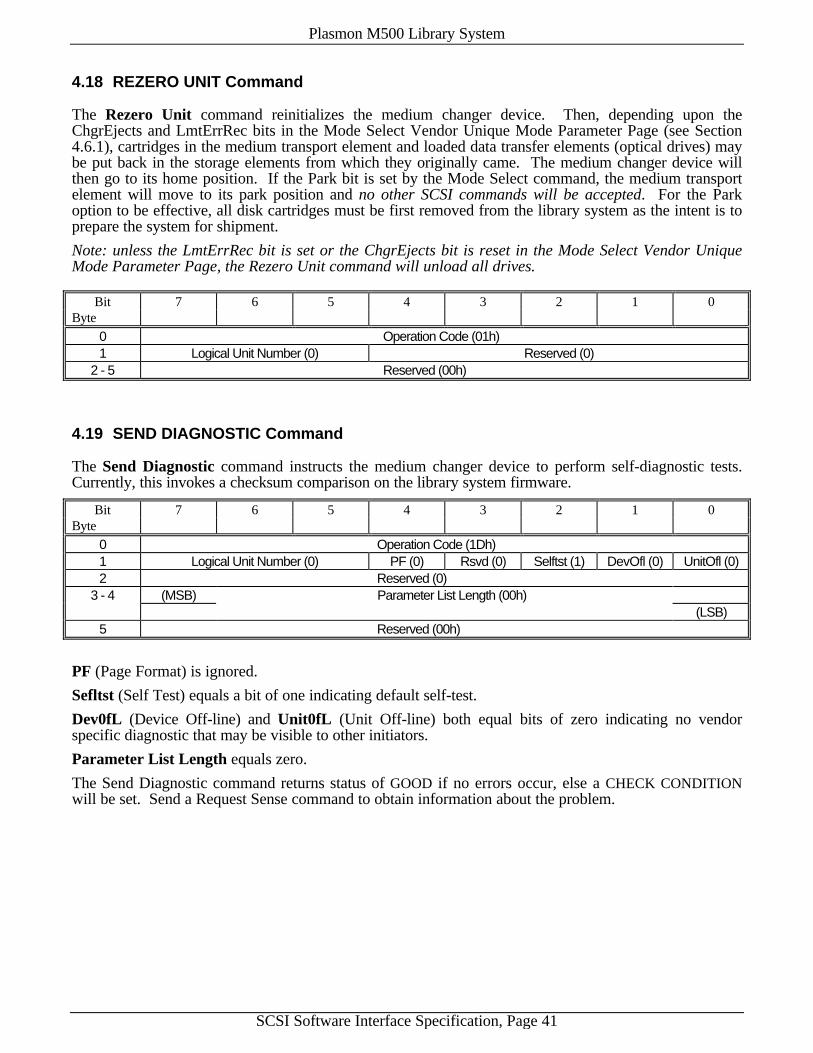
Plasmon M500 Library System
SCSI Software Interface Specification, Page 41
4.18 REZERO UNIT Command
The Rezero Unit command reinitializes the medium changer device. Then, depending upon theChgrEjects and LmtErrRec bits in the Mode Select Vendor Unique Mode Parameter Page (see Section4.6.1), cartridges in the medium transport element and loaded data transfer elements (optical drives) maybe put back in the storage elements from which they originally came. The medium changer device willthen go to its home position. If the Park bit is set by the Mode Select command, the medium transportelement will move to its park position and no other SCSI commands will be accepted. For the Parkoption to be effective, all disk cartridges must be first removed from the library system as the intent is toprepare the system for shipment.
Note: unless the LmtErrRec bit is set or the ChgrEjects bit is reset in the Mode Select Vendor UniqueMode Parameter Page, the Rezero Unit command will unload all drives.
Bit 7 6 5 4 3 2 1 0Byte
0 Operation Code (01h)1 Logical Unit Number (0) Reserved (0)
2 - 5 Reserved (00h)
4.19 SEND DIAGNOSTIC Command
The Send Diagnostic command instructs the medium changer device to perform self-diagnostic tests.Currently, this invokes a checksum comparison on the library system firmware.
Bit 7 6 5 4 3 2 1 0Byte
0 Operation Code (1Dh)1 Logical Unit Number (0) PF (0) Rsvd (0) Selftst (1) DevOfl (0) UnitOfl (0)2 Reserved (0)
3 - 4 (MSB) Parameter List Length (00h)(LSB)
5 Reserved (00h)
PF (Page Format) is ignored.
Sefltst (Self Test) equals a bit of one indicating default self-test.
Dev0fL (Device Off-line) and Unit0fL (Unit Off-line) both equal bits of zero indicating no vendorspecific diagnostic that may be visible to other initiators.
Parameter List Length equals zero.
The Send Diagnostic command returns status of GOOD if no errors occur, else a CHECK CONDITIONwill be set. Send a Request Sense command to obtain information about the problem.
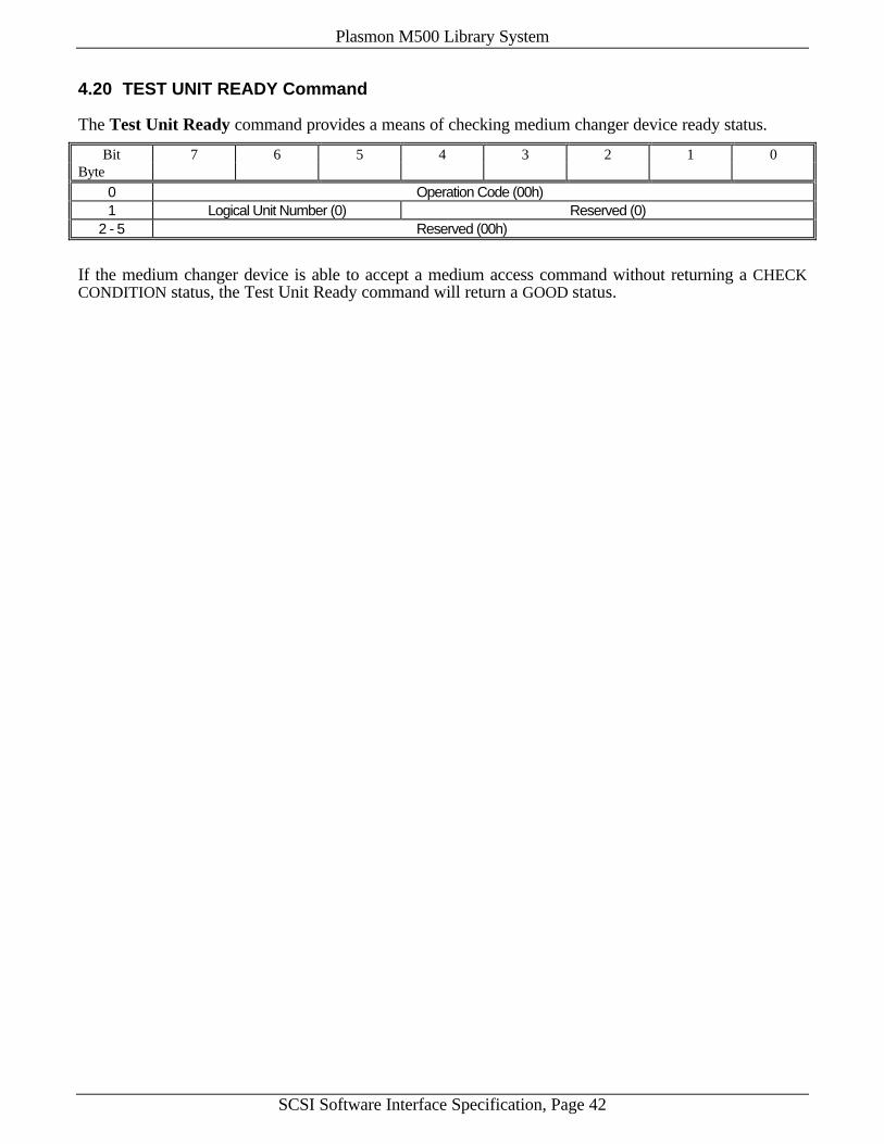
Plasmon M500 Library System
SCSI Software Interface Specification, Page 42
4.20 TEST UNIT READY Command
The Test Unit Ready command provides a means of checking medium changer device ready status.
Bit 7 6 5 4 3 2 1 0Byte
0 Operation Code (00h)1 Logical Unit Number (0) Reserved (0)
2 - 5 Reserved (00h)
If the medium changer device is able to accept a medium access command without returning a CHECKCONDITION status, the Test Unit Ready command will return a GOOD status.

Plasmon M500 Library System
SCSI Software Interface Specification, Page 43
This page intentionally left blank.
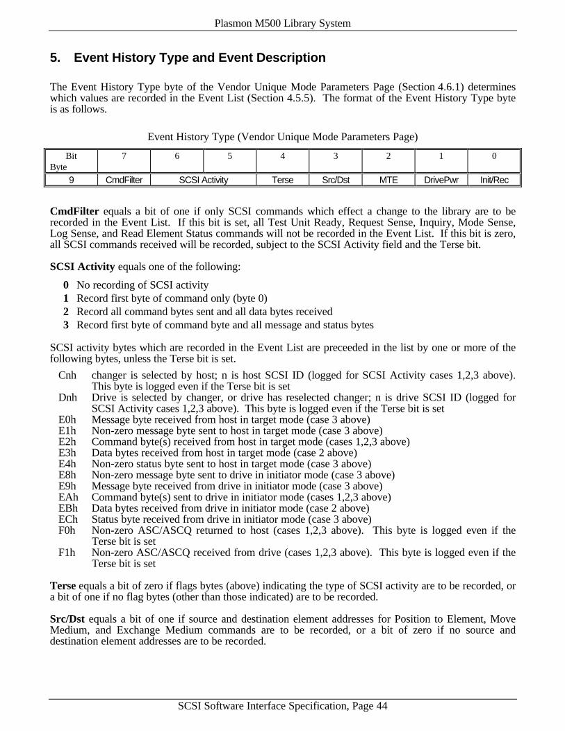
Plasmon M500 Library System
SCSI Software Interface Specification, Page 44
5. Event History Type and Event Description
The Event History Type byte of the Vendor Unique Mode Parameters Page (Section 4.6.1) determineswhich values are recorded in the Event List (Section 4.5.5). The format of the Event History Type byteis as follows.
Event History Type (Vendor Unique Mode Parameters Page)
Bit 7 6 5 4 3 2 1 0Byte
9 CmdFilter SCSI Activity Terse Src/Dst MTE DrivePwr Init/Rec
CmdFilter equals a bit of one if only SCSI commands which effect a change to the library are to berecorded in the Event List. If this bit is set, all Test Unit Ready, Request Sense, Inquiry, Mode Sense,Log Sense, and Read Element Status commands will not be recorded in the Event List. If this bit is zero,all SCSI commands received will be recorded, subject to the SCSI Activity field and the Terse bit.
SCSI Activity equals one of the following:
0 No recording of SCSI activity1 Record first byte of command only (byte 0)2 Record all command bytes sent and all data bytes received3 Record first byte of command byte and all message and status bytes
SCSI activity bytes which are recorded in the Event List are preceeded in the list by one or more of thefollowing bytes, unless the Terse bit is set.
Cnh changer is selected by host; n is host SCSI ID (logged for SCSI Activity cases 1,2,3 above).This byte is logged even if the Terse bit is set
Dnh Drive is selected by changer, or drive has reselected changer; n is drive SCSI ID (logged forSCSI Activity cases 1,2,3 above). This byte is logged even if the Terse bit is set
E0h Message byte received from host in target mode (case 3 above)E1h Non-zero message byte sent to host in target mode (case 3 above)E2h Command byte(s) received from host in target mode (cases 1,2,3 above)E3h Data bytes received from host in target mode (case 2 above)E4h Non-zero status byte sent to host in target mode (case 3 above)E8h Non-zero message byte sent to drive in initiator mode (case 3 above)E9h Message byte received from drive in initiator mode (case 3 above)EAh Command byte(s) sent to drive in initiator mode (cases 1,2,3 above)EBh Data bytes received from drive in initiator mode (case 2 above)ECh Status byte received from drive in initiator mode (case 3 above)F0h Non-zero ASC/ASCQ returned to host (cases 1,2,3 above). This byte is logged even if the
Terse bit is setF1h Non-zero ASC/ASCQ received from drive (cases 1,2,3 above). This byte is logged even if the
Terse bit is set
Terse equals a bit of zero if flags bytes (above) indicating the type of SCSI activity are to be recorded, ora bit of one if no flag bytes (other than those indicated) are to be recorded.
Src/Dst equals a bit of one if source and destination element addresses for Position to Element, MoveMedium, and Exchange Medium commands are to be recorded, or a bit of zero if no source anddestination element addresses are to be recorded.

Plasmon M500 Library System
SCSI Software Interface Specification, Page 45
For clarity and to save space in the Event List, drives are logged as D1h, D2h, etc.; MTE's are logged asE1h and E2h; the Import/Export is logged as EEh; slot numbers less than 200 are logged as one byte; andslot numbers greater than or equal to 200 are logged as two - the first (MSB) being OR'd with FCh.
For example, the following is the Event List of an Exchange Medium from SE1 to D1 to SE255:
C7 (E2) A6 (...) 01 D1 FC FF
MTE equals a bit of one if the medium transport element used for Position to Element, Move Medium,and Exchange Medium commands is to be recorded, or a bit of zero if the medium transport element isnot to be recorded
The MTE used is logged as E1h or E2h (for MTE1 or MTE2, respectively). If the default address ofzero is specified for the Exchange Medium command, then E3h is logged if the exchange begins withMTE1 or E4h is logged if the exchange begins with MTE2. The MTE used is logged after the sourceand destination element bytes if the Src/Dst bit is set.
DrivePwr equals a bit of one if flag bytes for drive power cycling are to be recorded, or a bit of zero ifno flag bytes for drive power cycling are to be recorded.
The following flag bytes are recorded for drive power cycling.
F2h Drive power cycled because cartridge did not load into driveF3h Drive power cycled because cartridge popped out after loadF4h Drive power cycled because drive did not become ready after loadF5h Drive power cycled because cartridge could not be ejectedF7h Drive power removed because drive was taken off-lineF8h Drive power applied because drive was brought back on-lineF9h Drive power cycled because drive SCSI ID was changed
Init/Rec equals a bit of one if the library system initialize and recovery sequence is to be recorded, or abit of zero if the initialize and recovery sequence is not to be recorded.
The initialize and recovery sequence consists of one byte values all of which are less than 100.
Finally, the following bytes are always recorded for a non-zero Event History Type.
FEh SCSI bus or device resetFFh Power-on

Plasmon M500 Library System
SCSI Software Interface Specification, Page 46
6. Error Codes
6.1 Medium Changer Device SCSI Error Codes
The following is a list of error codes returned by a Request Sense command issued to the medium changer device within thelibrary. The codes are listed in ASC, ASCQ order. See the Request Sense command, Section 4.16, for adescription of the Sense Key values. Errors listed here with a Sense Key of 04h, hardware error, mayalso be returned with a Sense Key of 01h, recovered error. This indicates that the command wassuccessful although the library did have some difficulty in completing the command. Recovered errorsindicate a possible problem with the library.
Error codes returned by optical drives within the library system are not listed — see the appropriate drivemanuals for a description of these errors.
Also listed are the internal error codes associated with the SCSI error returned, and the procedures that ahost may use to recover when it has received one of the errors listed here. See Section 6.3 for a list ofthe internal library error codes, and the M500 User’s Manual or Service Manual for the cause orcorrective action for each code. Refer to the next section for a list of the suggested host error recoveryprocedures. Not all errors have host recovery procedures. It should be noted that the library systemattempts extensive error recovery on its own.
SenseKey ASC ASCQ Error Description
InternalError
RecoveryProcedure
02h 04h 01h Logical Unit is in process of becoming ready - 105h 1Ah 00h Parameter list length error - 205h 20h 00h Invalid command operation code - 205h 21h 01h Invalid element address - 205h 24h 00h Invalid field in CDB - 205h 25h 00h Logical Unit not supported - 305h 26h 00h Invalid field in parameter list - 405h 28h 01h Import/Export element accessed - 506h 29h 00h Power-on, Reset, or Bus Device Reset occurred - 606h 2Ah 00h Log Parameters changed - 706h 2Ah 01h Mode parameters changed - 805h 3Bh 0Dh Medium destination element full 1Ch 905h 3Bh 0Eh Medium source element empty 1Bh 905h 3Dh 00h Invalid bits in identify message - 1004h 40h 00h Diagnostic failure (EPROM) - 1004h 43h 00h Message error - 1004h 44h 00h Internal target failure - 1004h 45h 00h Select or Reselect failure - 1004h 47h 00h SCSI parity error - 1004h 48h 00h Initiator detected error message received - 1004h 49h 00h Invalid message error - 1004h 4Bh 00h Data Phase error - 1005h 53h 02h Medium removal prevented 2Dh 1104h 80h 11h Slave CPU communication failure 11h 1004h 80h 12h Park failure 12h -04h 80h 15h Pivot cable failure 15h -04h 80h 16h Drive interface board disconnected 16h -04h 80h 17h Lift cable failure 17h -04h 80h 18h Main harness lower (CJ8) cable failure 18h -04h 80h 19h Main harness upper (CJ1) cable failure 19h -04h 80h 1Ah Drive not installed 1Ah 12
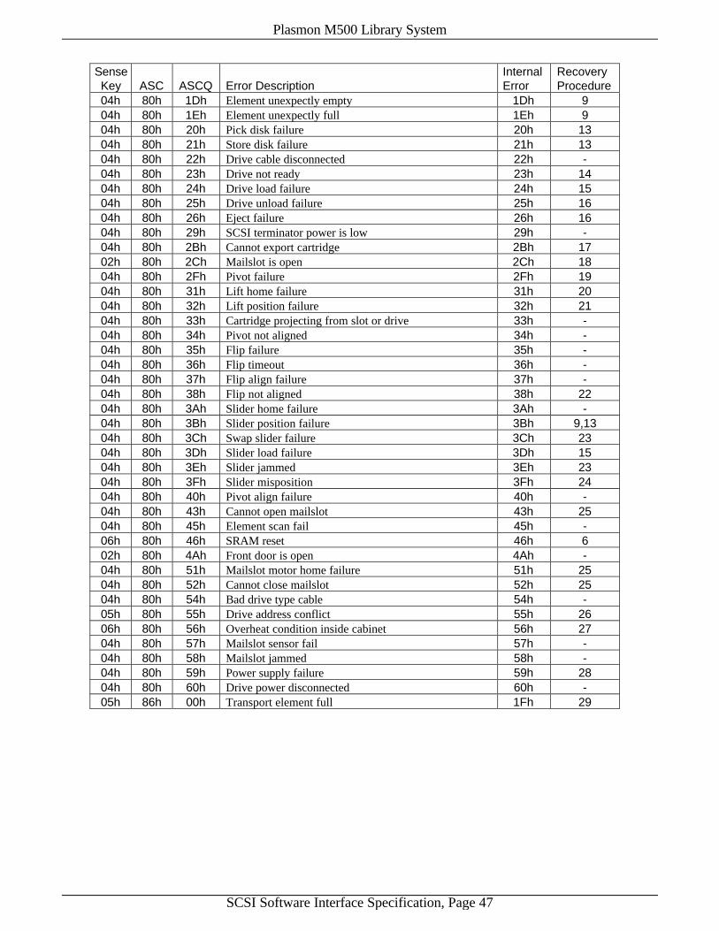
Plasmon M500 Library System
SCSI Software Interface Specification, Page 47
SenseKey ASC ASCQ Error Description
InternalError
RecoveryProcedure
04h 80h 1Dh Element unexpectly empty 1Dh 904h 80h 1Eh Element unexpectly full 1Eh 904h 80h 20h Pick disk failure 20h 1304h 80h 21h Store disk failure 21h 1304h 80h 22h Drive cable disconnected 22h -04h 80h 23h Drive not ready 23h 1404h 80h 24h Drive load failure 24h 1504h 80h 25h Drive unload failure 25h 1604h 80h 26h Eject failure 26h 1604h 80h 29h SCSI terminator power is low 29h -04h 80h 2Bh Cannot export cartridge 2Bh 1702h 80h 2Ch Mailslot is open 2Ch 1804h 80h 2Fh Pivot failure 2Fh 1904h 80h 31h Lift home failure 31h 2004h 80h 32h Lift position failure 32h 2104h 80h 33h Cartridge projecting from slot or drive 33h -04h 80h 34h Pivot not aligned 34h -04h 80h 35h Flip failure 35h -04h 80h 36h Flip timeout 36h -04h 80h 37h Flip align failure 37h -04h 80h 38h Flip not aligned 38h 2204h 80h 3Ah Slider home failure 3Ah -04h 80h 3Bh Slider position failure 3Bh 9,1304h 80h 3Ch Swap slider failure 3Ch 2304h 80h 3Dh Slider load failure 3Dh 1504h 80h 3Eh Slider jammed 3Eh 2304h 80h 3Fh Slider misposition 3Fh 2404h 80h 40h Pivot align failure 40h -04h 80h 43h Cannot open mailslot 43h 2504h 80h 45h Element scan fail 45h -06h 80h 46h SRAM reset 46h 602h 80h 4Ah Front door is open 4Ah -04h 80h 51h Mailslot motor home failure 51h 2504h 80h 52h Cannot close mailslot 52h 2504h 80h 54h Bad drive type cable 54h -05h 80h 55h Drive address conflict 55h 2606h 80h 56h Overheat condition inside cabinet 56h 2704h 80h 57h Mailslot sensor fail 57h -04h 80h 58h Mailslot jammed 58h -04h 80h 59h Power supply failure 59h 2804h 80h 60h Drive power disconnected 60h -05h 86h 00h Transport element full 1Fh 29

Plasmon M500 Library System
SCSI Software Interface Specification, Page 48
6.2 Medium Changer Device Error Host Recovery Procedures
The following is a list of procedures that a host could use to recover from the SCSI errors listed in theprevious section. In some, if not most cases, no action taken by the host will cause full recovery to takeplace and the M500 User’s Guide or Service Manual should be consulted to determine the ultimate causeor corrective action to be taken to rectify the problem. Many situations call for operator intervention.
Procedure Description1 Delay a few seconds and then retry command.2 Examine command block for errors. Sense data identifies offending byte and field.3 Examine command block or Identify message for non-zero LUN value.4 Examine parameter list for errors. Sense data identifies offending byte and field.5 If Position to Element command, position to mailslot with other transport element or use
default transport element address of zero. If Move Medium command, do not attempt tomove from mailslot to mailslot with Invert bit set.
6 Determine cause of reset, reselect mode parameters not previously saved, and resubmitcommand.
7 Issue Log Sense, if desired, to obtain log parameters changed via front panel or by anotherhost, and then resubmit original command.
8 Issue Mode Sense, if desired, to obtain mode parameters changes via front panel or byanother host, and then resubmit original command.
9 Issue Initialize Element Status and Read Element Status commands to reinventory library.Note on 3B 0D: if using Rezero to park the library, all drives and slots must be empty first.
10 Issue Bus Device Reset to changer device or assert SCSI bus reset line and retry command.11 Wait for other host to issue Prevent Allow Medium Removal command to allow access to
mailslot, or issue Bus Device Reset to changer device and retry command.12 Power up the drive and place it on-line via the Mode Select command before trying to move
to or from it.13 Issue Position to Element command to any storage element with the Invert bit set. This
causes the transport element to be placed in the flipped position. Retry the move or exchangecommand. If this does not work, specify a transport element address other than zero in themove or exchange command. Use the medium transport element not active at the time thatthe error occurred. The medium transport element that was active is identified in the RequestSense return data. Note: specifying a non-zero transport element address in the ExchangeMedium command may allow the library to operate but at reduced performance.
14 Reload drive by issuing a Move Medium command with the drive as the source anddestination address. If this does not work, load the drive and then use the Mode Selectcommand, Drive Assignments Page, to first power-off the drive and then, after a few seconds,to power-on the drive again. Wait a few seconds before issuing a Test Unit Ready to thedrive to check for ready status.
15 Specify a non-zero transport element address in the move or exchange command. Use themedium transport element not active at the time that the error occurred. The mediumtransport element that was active is identified in the Request Sense return data. If this doesnot work, issue the Initialize Element Status and Read Element Status commands toreinventory the drives. If the drive is truly empty, issue the Mode Select command with theDrive Assignments page to cycle power to the drive as in procedure 14 and then reinventorythe drives. Setting the NoScanSE bit in the Mode Select Vendor Unique Special Modes Pagewill make drive reinventory go faster.
16 Issue the Initialize Element Status and Read Element Status commands to reinventory thedrives. If the drive is truly full, issue the Mode Select command with the Drive Assignmentspage to cycle power to the drive as in procedure 14 and then reinventory the drives. Settingthe NoScanSE bit in the Mode Select Vendor Unique Special Modes Page will make drivereinventory go faster.
17 If Rezero Unit command, move cartridges from medium transport elements and drives beforeissuing command, or set Limited Recovery flag using Mode Select command before issuingcommand. If not Rezero Unit, move cartridge from mailslot and and then retry command.
18 Issue Open/Close Mailslot command to close the mailslot and then retry command.

Plasmon M500 Library System
SCSI Software Interface Specification, Page 49
Procedure Description19 Issue Position to Element command to pivot to column further away than desired destination
and then retry command.20 Issue Open/Close Mailslot command to close the mailslot and then retry command.21 If a medium transport element is full, move the cartridge to the nearest element and then
retry the command. This will lighten the transport assembly.22 Issue a Position to Element command and then retry the original command.23 Specify a non-zero transport element address in the move or exchange command. Use the
medium transport element active at the time that the error occurred. The medium transportelement that was active is identified in the Request Sense return data. Note: specifying anon-zero transport element address in the Exchange Medium command may allow the libraryto operate but at reduced performance.
24 Issue a Rezero Unit command and then retry the original command.25 Issue a Position to Element command to move away from the mailslot and then issue an
Open/Close Mailslot command to open or close the mailslot.26 Issue a Mode Sense command with the Drive Assignments page to determine the SCSI ID’s
of on-line drives and then issue the Mode Select command with the same page to set the SCSIID of the drive to be powered-on to a non-conflicting address (and non-conflicting with themedium changer device if on the same SCSI bus). Finally, issue a Mode Select commandwith the same page to power-on the drive.
27 Decrease drive read/write activity until cabinet temperature has cooled down significantly.Use the Mode Select command to power-down unused drives. The internal cabinettemperature can be read using the Mode Sense command.
28 Use drives attached to a different power supply. Drives 2 and 4 are attached to power supply1; drives 1, 3, 5, and 6 are attached to power supply 2.
29 Use the Move Medium command to move the cartridge out of the medium transport element.
6.3 Internal Error Codes
The following error codes are stored in the library system error log and error statistics buffers and arereturned by the Log Sense command. For more information about the causes and corrective actions forthese errors, refer to the M500 User’s Guide or Service Manual.
Error Code Error Description11h Slave CPU communication failure12h Park failure15h Pivot cable failure16h Drive interface board disconnected17h Lift cable failure18h Main harness lower (CJ8) cable failure19h Main harness upper (CJ1) cable failure1Ah Drive not installed1Bh Source is empty1Ch Destination is full1Dh Element unexpectedly empty1Eh Element unexpectedly full1Fh Lift is full20h Pick disk failure21h Store disk failure22h Drive cable disconnected23h Drive not ready24h Drive load failure25h Drive unload failure26h Eject failure28h Can't inquiry drive29h SCSI terminator power is low
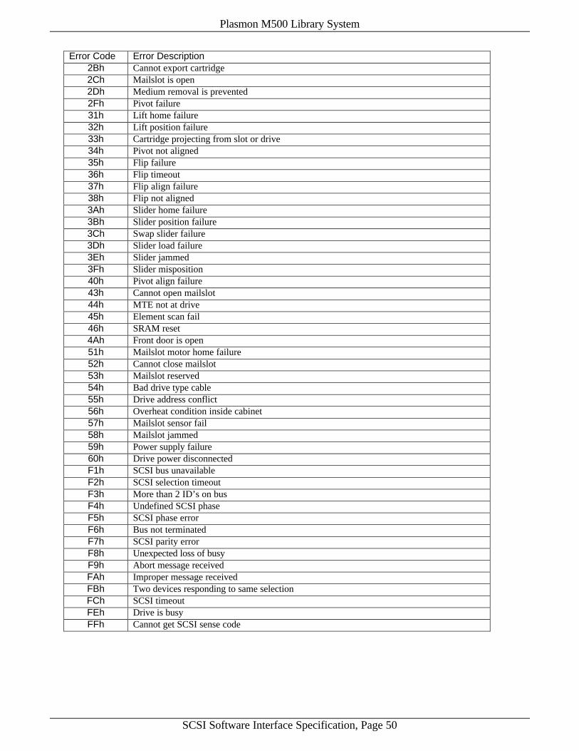
Plasmon M500 Library System
SCSI Software Interface Specification, Page 50
Error Code Error Description2Bh Cannot export cartridge2Ch Mailslot is open2Dh Medium removal is prevented2Fh Pivot failure31h Lift home failure32h Lift position failure33h Cartridge projecting from slot or drive34h Pivot not aligned35h Flip failure36h Flip timeout37h Flip align failure38h Flip not aligned3Ah Slider home failure3Bh Slider position failure3Ch Swap slider failure3Dh Slider load failure3Eh Slider jammed3Fh Slider misposition40h Pivot align failure43h Cannot open mailslot44h MTE not at drive45h Element scan fail46h SRAM reset4Ah Front door is open51h Mailslot motor home failure52h Cannot close mailslot53h Mailslot reserved54h Bad drive type cable55h Drive address conflict56h Overheat condition inside cabinet57h Mailslot sensor fail58h Mailslot jammed59h Power supply failure60h Drive power disconnectedF1h SCSI bus unavailableF2h SCSI selection timeoutF3h More than 2 ID’s on busF4h Undefined SCSI phaseF5h SCSI phase errorF6h Bus not terminatedF7h SCSI parity errorF8h Unexpected loss of busyF9h Abort message receivedFAh Improper message receivedFBh Two devices responding to same selectionFCh SCSI timeoutFEh Drive is busyFFh Cannot get SCSI sense code
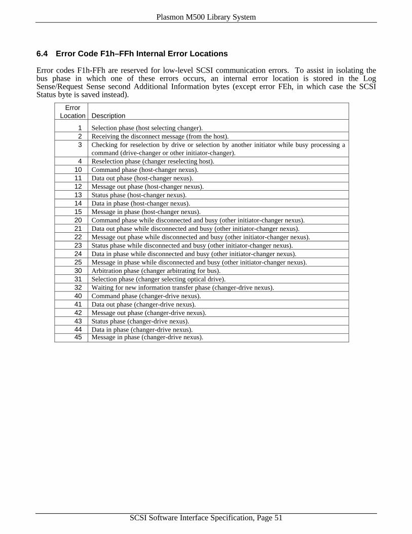
Plasmon M500 Library System
SCSI Software Interface Specification, Page 51
6.4 Error Code F1h–FFh Internal Error Locations
Error codes F1h-FFh are reserved for low-level SCSI communication errors. To assist in isolating thebus phase in which one of these errors occurs, an internal error location is stored in the LogSense/Request Sense second Additional Information bytes (except error FEh, in which case the SCSIStatus byte is saved instead).
ErrorLocation Description
1 Selection phase (host selecting changer).2 Receiving the disconnect message (from the host).3 Checking for reselection by drive or selection by another initiator while busy processing a
command (drive-changer or other initiator-changer).4 Reselection phase (changer reselecting host).
10 Command phase (host-changer nexus).11 Data out phase (host-changer nexus).12 Message out phase (host-changer nexus).13 Status phase (host-changer nexus).14 Data in phase (host-changer nexus).15 Message in phase (host-changer nexus).20 Command phase while disconnected and busy (other initiator-changer nexus).21 Data out phase while disconnected and busy (other initiator-changer nexus).22 Message out phase while disconnected and busy (other initiator-changer nexus).23 Status phase while disconnected and busy (other initiator-changer nexus).24 Data in phase while disconnected and busy (other initiator-changer nexus).25 Message in phase while disconnected and busy (other initiator-changer nexus).30 Arbitration phase (changer arbitrating for bus).31 Selection phase (changer selecting optical drive).32 Waiting for new information transfer phase (changer-drive nexus).40 Command phase (changer-drive nexus).41 Data out phase (changer-drive nexus).42 Message out phase (changer-drive nexus).43 Status phase (changer-drive nexus).44 Data in phase (changer-drive nexus).45 Message in phase (changer-drive nexus).

Plasmon M500 Library System
SCSI Software Interface Specification
© Copyright 1999 by Plasmon IDE.
