plastic collapse
TRANSCRIPT

rp clarke 1
CE 31B STRUCTURAL ENGINEERING
PLASTIC COLLAPSE METHOD
OUTLINE OF TOPICS
(3 No. Sessions at 1 hr each) by R. Clarke
Delivery Media: Equipment:
Objective: Introduction to practical limit analysis applied to portal frames. Scope/Limitations: Mainly Upper bound theorem; shakedown not considered; displacements after initial hinging not considered. Primary Approach: Procedure-Based; Graphics-Based; Example-Based. TOPICS 1.0 Introduction
1.1 Elastic-Plastic Flexural Relations 1.2 Behaviour of a Loaded Beam 1.3 General Structural Action
2.0 Collapse Mechanisms and Conditions
2.1 Definition of Collapse Mechanism 2.2 General Collapse Conditions
3.0 The Plastic Collapse Theorems 4.0 Elementary Mechanisms and Combined Mechanisms
Oral Blackboard Handouts Slides/Transpar-encies
Slide Projector Transparency Projector
Internet
Computer Projector

rp clarke 2
1.0 Introduction The plastic collapse methods are means for the determination of the failure load on a structure. Such methods, also known as limit analysis, are based on the consideration of the mechanics of a structure after the onset of plasticity at a sufficient number of points in the structure that the structure can no longer sustain load. In the modern ultimate strength design philosophy, the analysis is nevertheless elastic thereby introducing a degree of logical inconsistency since the material is typically performing in the inelastic range. A plastic analysis on the other hand implicitly considers the full spectrum of response including the phenomena at the ultimate limit state and is therefore logically consistent. For a significant number of structures, the underlying assumptions of the plastic collapse methods are sufficiently true that predicted behaviour of these structures agree very well with real behaviour.
1.1 Elastic-Plastic Flexural Relations For simple beams, the moment-curvature relationship for a rectangular cross-section of an homogeneous and isotropic material is similar to curve OAB. For M < My the section behaves elastically, giving the straight line OA. At A, M equals the yield moment My, and the M-φ relation is no longer linear. Finally, as the moment tends towards the fully plastic moment, the curvature φ tends to infinity. The ratio of the fully plastic moment Mp to the yield moment is called the shape factor: Mp/My = ν = 1.5 for a rectangle For an I-section the shape factor is about 1.15 and the M-φ relation is as the dotted line which has a well-defined knee. The differences in the shape factor for different types of section, is a reflection of the fact that for equilibrium of the section, different sections have different regions where plastic flow is occurring. If the shape factor becomes unity the curve becomes bi-linear and consists of a region of perfect elasticity OA’ and the perfectly plastic range A’B where the curvature can increase indefinitely at constant moment (i.e. elastic-perfectly plastic). Throughout the following, it is assumed that the material section is elastic-perfectly plastic.
Mp
My
A’ B
A
φ O
φ
M M

rp clarke 3
1.2 Behaviour of a Loaded Beam
(a) Single-Hinge Case: In general, the bending moment along a beam is not uniform and in the centrally-loaded beam, the maximum moment occurs at a single cross-section. If the load-point deflection d is recorded while the load W increases from zero, the initial behaviour will be elastic to give the straight line OA. When the maximum moment reaches the fully plastic moment, a very large curvature is now possible and the deflection increases with no change in load (i.e. A to B). The bending moments along the beam are everywhere less than the maximum (i.e. less than Mp) except at the load point, so that the large curvature is concentrated at the one cross-section. Hence there is a “hingeing” action and the beam develops a clearly-defined kink called a plastic hinge. Deformations away from the hinge are everywhere elastic and, since the plastic deformations in the hinge occur under constant moment, the elastic deformations remain unchanged and all displacements after point A is reached, are due to plastic deformation in the hinge zone. (b) Two-Hinge Case Consider the propped-cantilever (which is statically indeterminate). As long as the beam remains elastic, normal elastic analysis gives the bending moment diagram, which is shown on the left via the superimposition method of presenting BMDs. The load W can increase until the moment at A (which is the maximum) reaches the plastic moment of the section at A, Mp. That is, 5WL/27 = Mp or W = 27Mp/5L (1)
W
d
W
d
A B
O W
W A B C
L/3 2L/3
δW A B C
Mp
Mp = 2WL/15
2 (δW)L/9
5WL/27
8WL/81
WL/Mp
d2d1
15/2
27/5
O
E
F
2/3Mp

rp clarke 4
The moment at A cannot increase further and the curvature can increase indefinitely, so that additional load δW can cause no change in MA, and no additional resistance to rotation is offered at A. Therefore, the additional load must be carried as if the beam is simply-supported (centre diagrams). Statically however, we must input Mp at A. Note that this induces a linearly varying moment, called the reactant bending moment diagram, along the beam that is of value 2Mp/3 at point B. By increasing the load by δW, additional moments are induced along the beam for equilibrium, which are found by application of simple statics (centre diagram). The increasing load continues until the total moment at B equals the plastic moment Mp. During this stage, plastic rotation continues at A. Hence eventually, at MB = Mp, 8WL/81 + 2δWL/9 = Mp (2) But W is the load that caused the hinge at A so substituting for W from (1) into (2) and making δW the subject, we get δW = 21Mp/10L (3) Hence the total load required to cause the hinge at B = W + δW = 15Mp/2L However, attempts to add further load fail since neither MA nor MB can increase so that equilibrium is not possible under additional load and indefinite rotation would occur at A and B. The beam then becomes a two-bar mechanism and will collapse by excessive rotation at these two locations. That is, A and B are in effect, hinges of a mechanism. Note that if we knew beforehand that the hinges would in fact form at A and B, then we can calculate the collapse load directly from statics, MB = MP + 2MP/3 must be in equilibrium with the applied moment at the section which is given by 2PL/9. Hence, P = 15Mp/2L At this point it is useful to introduce the idea of the collapse load factor or simply load factor, λ. The collapse load factor is the ratio of the collapse load to the working load. Hence in the above case, λW = P = 15Mp/2L hence λ = 7.5Mp/WL Also, it is noteworthy that a set of loads can be represented as ratios of one of the loads. Therefore, though there may be many loads on the structure, there is only one collapse load λ for the set of loads.
1.3 General Structural Action Though the examples above are for simple cases, the behaviour can be generalised for more complex structures as follows:- 1. A perfectly elastic-pastic structural member behaves elastically until a plastic
hinge is formed at one section. 2. Additional load may be carried if rotation at this hinge allows diffusion (i.e
redistribution) of the load to other stable parts of the structure. 3. As each plastic hinge is formed, the moment remains constant at the fully-plastic
value irrespective of deformation or additional load. 4. Collapse occurs when there is no more remaining stable element that can carry the
additional load. 5. At collapse, the structure as a whole, or in part, forms a simple mechanism.

rp clarke 5
6. If the locations of plastic hinges can be predicted, the collapse load is readily calculated by simple statics.
This approach to determining the collapse load is called the Statics Method or the Graphics Method and is used in the application of the Lower Bound Theorem also known as the Safe Theorem. There is another approach to determining the collapse load and it is called the Mechanism Method or the Work Method and is used in the application of the Upper Bound Theorem also called the Unsafe Theorem or the Kinematic Theorem. Though the examples demonstrate the use of the Statics Method in calculating the collapse load, the Work Method will be the focus of this presentation on plastic collapse methods. The Statics Method can become unwieldy for all but the simplest cases. 2.0 Collapse Mechanisms and Conditions
2.1 Definition of the Collapse Mechanism The insertion of a real hinge, or pin joint, into a statically indeterminate stiff frame reduces the number of indeterminate moments by one. Hence, if the number of indeterminacies is n, the addition of n hinges produces a simple statically determinate structure. The addition of one more hinge will allow the structure to move with one degree of freedom. That is, a mechanism is formed when the number of hinges to form a mechanism is (n + 1). From elementary structural mechanics, we are reminded that the number of indeterminacies in a 2D (rigid-jointed) frame is: 3m + r – 3j, where m is the number of members, r is the number of independent reactions, and j is the number of joints (including at the supports). So, the number of hinges required to form a mechanism for a 2D rigid-jointed frame is (3m + r – 3j + 1). For a beam, the number of indeterminacies is 2m + r – 2j since there is no horizontal reaction. These criteria must be applied to each element of a structure as well as to the structure as a whole, because collapse of one part represents practical failure.
2.2 General Collapse Conditions Given the aforementioned, there are three necessary and sufficient conditions attending collapse of a structure: When a structure is just on the point of collapse: (a) The Equilibrium Condition The system of bending moments must be in equilibrium with the external loads. (b) The Yield Condition The bending moments may nowhere exceed the plastic moment values of the members. (c) Mechanism Condition There must be sufficient plastic hinges to form a mechanism. If a system of bending moments can be found which satisfies these three conditions, then that system defines the true collapse load.

rp clarke 6
3.0 The Plastic Collapse Theorems The above are the complete conditions for collapse. However, to determine the collapse load mathematically, two approaches become apparent where each approach is derived from what you take as your starting point – If your starting point is the structure on the verge of becoming a mechanism, in other words, the hinges are just about to form, then we get the Lower Bound Theorem. In this case, we are guaranteed that the yield condition is not violated at any point in the structure. Hence, the Lower Bound or Lower Limit Theorem is also called the Safe Theorem. It is stated as: If any bending moment distribution can be found which satisfies the equilibrium condition and the yield condition (i.e. bending moments nowhere exceed Mp), that system is safe and statically sufficient and the corresponding load system is less than or equal to the true collapse load of the structure. Hence if λP is the true collapse load, and λ’P is the collapse load calculated by the lower bound theory, then λ ≥ λ’, where λ is the collapse load factor. It also means that the loads which cause the bending moment diagram that you start with, may need to be increased for collapse to occur. If your starting point is a mechanism, in other words, the hinges have already formed and may be at different levels of curvature, then we get the Upper Bound Theorem. In this case, we are not guaranteed that the yield condition is not violated at any point in the structure. Hence, the Upper Bound or Upper Limit Theorem is also called the Unsafe Theorem. It is stated as: If a collapse mechanism can be found such that the associated moments satisfy the equilibrium condition and the mechanism condition, then the mechanism is kinematically sufficient and the corresponding load system is greater than or equal to the true collapse load. Hence if λP is the true collapse load, and λ’P is the collapse load calculated by the upper bound theory, then λ’ ≥ λ, where λ is the collapse load factor. It also means that the mechanism you start with may not be the first to form as load increases, and another mechanism may have formed at a lower load. When all three conditions are satisfied then the collapse load is unique and is the true collapse load. This is called the Uniqueness Theorem. The collapse theorems can be summarised as: Uniqueness Theorem: Mechanism Condition Upper Bound Theorem: λ’ = λ Equilibrium Condition λ’ ≥ λ Yield Condition Lower Bound Theorem: λ ≥ λ’ The proof of these theorems is left as a subject for research by the student. Note that the Upper and Lower Bound theorems are stated as inequalities, so something else is required to arrive at the true collapse load. In general, the two methods are combined but either one or the other remains predominant. The process is as follows:-

rp clarke 7
If the Upper Bound Theorem approach is predominant (Work Method): 1. Determine a set of possible mechanisms 2. For each mechanism use the virtual work equations and determine the collapse
load. 3. Choose the mechanism that gives the lowest collapse load. 4. By statics, determine the BMD for the selected mechanism. If the yield moment
Mp is nowhere exceeded, the Uniqueness Theorem guarantees that the collapse load for that mechanism, is the true collapse load. If Mp is exceeded anywhere, the search must continue for the correct mechanism.
If the Lower Bound Theorem approach is predominant (Statics Method): 1. Draw a statically determinate BMD 2. Superimpose the reactant BMD 3. Choose where plastic hinges are likely to occur. 4. By statics, determine the collapse load. 5. Examine possible alternative hinge locations and try to increase the collapse load. As stated earlier, except for very simple structures, the Upper Bound Theorem procedure is less tedious. This method also benefits from the fact that there is a systematic procedure for the determination of possible mechanisms. 4.0 Elementary Mechanisms and Combined Mechanisms The first step in the Upper Bound Theorem Procedure for the determination of the collapse load, is the determination of the mechanisms for investigation. This can be done by first identifying possible elementary mechanisms, and then systematically combining them to form combined mechanisms. Therefore, from this point onwards we focus on the Work Method. (a) Elementary Mechanisms For frame structures, the elementary mechanisms are – the beam and sway mechanisms. The principle of virtual work can be readily used to calculate the collapse load for the elementary mechanism. The central principle is that the work done in the plastic hinges by rotation of the section, must equal the external work done by the applied loads. Only the case of a single point load will be considered. 1. Beam mechanism: Consider the following uniform beam (i.e. Mp is the same at each section). m = 1 r = 3 j = 2, hence no. of hinges to form a mechanism = 2m+r-2j+1 = 2 Work done by external load = Pδ Work done in hinges = Work done in hinge at A + Work done in hinge at B tan θ = δ/xL hence δ = xL tan θ but for small angles tan θ = θ. Hence,
A
B
C
xL (1 – x)L
xθ/(1 – x) θ
θ/(1 – x)
P
δ
rp clarke 8
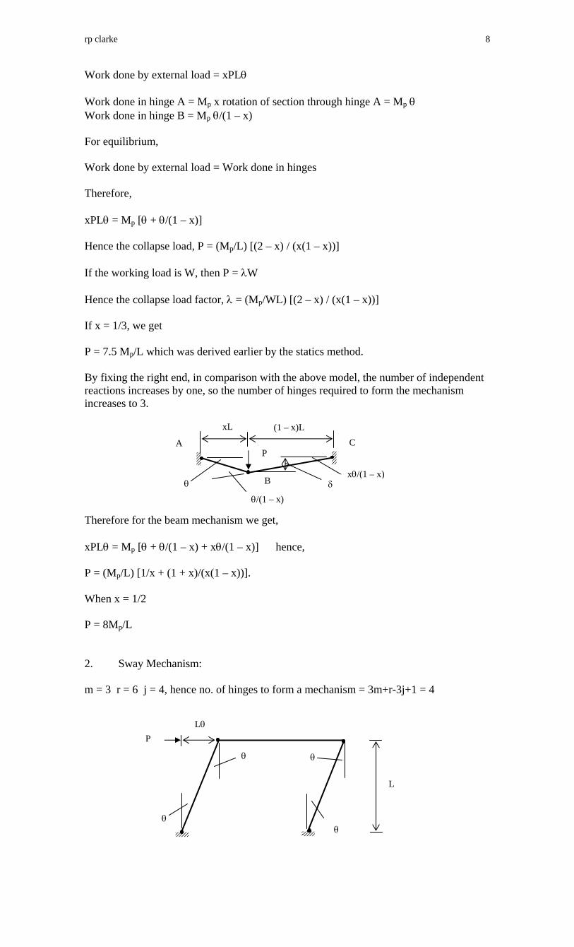
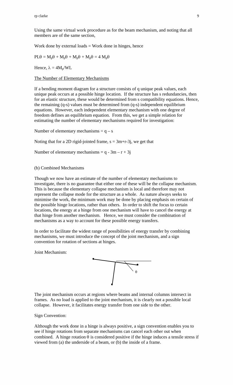
Work done by external load = xPLθ Work done in hinge A = Mp x rotation of section through hinge A = Mp θ Work done in hinge B = Mp θ/(1 – x) For equilibrium, Work done by external load = Work done in hinges Therefore, xPLθ = Mp [θ + θ/(1 – x)] Hence the collapse load, P = (Mp/L) [(2 – x) / (x(1 – x))] If the working load is W, then P = λW Hence the collapse load factor, λ = (Mp/WL) [(2 – x) / (x(1 – x))] If x = 1/3, we get P = 7.5 Mp/L which was derived earlier by the statics method. By fixing the right end, in comparison with the above model, the number of independent reactions increases by one, so the number of hinges required to form the mechanism increases to 3. Therefore for the beam mechanism we get, xPLθ = Mp [θ + θ/(1 – x) + xθ/(1 – x)] hence, P = (Mp/L) [1/x + (1 + x)/(x(1 – x))]. When x = 1/2 P = 8Mp/L 2. Sway Mechanism: m = 3 r = 6 j = 4, hence no. of hinges to form a mechanism = 3m+r-3j+1 = 4
θ
θ θ
θ
P
L
Lθ
A
B
C
xL (1 – x)L
xθ/(1 – x) θ
θ/(1 – x)
P
δ
rp clarke 9
Using the same virtual work procedure as for the beam mechanism, and noting that all members are of the same section, Work done by external loads = Work done in hinges, hence PLθ = Mpθ + Mpθ + Mpθ + Mpθ = 4 Mpθ Hence, λ = 4Mp/WL The Number of Elementary Mechanisms If a bending moment diagram for a structure consists of q unique peak values, each unique peak occurs at a possible hinge location. If the structure has s redundancies, then for an elastic structure, these would be determined from s compatibility equations. Hence, the remaining (q-s) values must be determined from (q-s) independent equilibrium equations. However, each independent elementary mechanism with one degree of freedom defines an equilibrium equation. From this, we get a simple relation for estimating the number of elementary mechanisms required for investigation: Number of elementary mechanisms = q – s Noting that for a 2D rigid-jointed frame, s = 3m+r-3j, we get that Number of elementary mechanisms = q - 3m – r + 3j (b) Combined Mechanisms Though we now have an estimate of the number of elementary mechanisms to investigate, there is no guarantee that either one of these will be the collapse mechanism. This is because the elementary collapse mechanism is local and therefore may not represent the collapse mode for the structure as a whole. As nature always seeks to minimise the work, the minimum work may be done by placing emphasis on certain of the possible hinge locations, rather than others. In order to shift the focus to certain locations, the energy at a hinge from one mechanism will have to cancel the energy at that hinge from another mechanism. Hence, we must consider the combination of mechanisms as a way to account for these possible energy transfers. In order to facilitate the widest range of possibilities of energy transfer by combining mechanisms, we must introduce the concept of the joint mechanism, and a sign convention for rotation of sections at hinges. Joint Mechanism: The joint mechanism occurs at regions where beams and internal columns intersect in frames. As no load is applied to the joint mechanism, it is clearly not a possible local collapse. However, it facilitates energy transfer from one side to the other. Sign Convention: Although the work done in a hinge is always positive, a sign convention enables you to see if hinge rotations from separate mechanisms can cancel each other out when combined. A hinge rotation θ is considered positive if the hinge induces a tensile stress if viewed from (a) the underside of a beam, or (b) the inside of a frame.
θ

rp clarke 10
This makes it possible to systematically derive combinations of mechanisms by setting up a table of the rotations for the elementary mechanisms, including the joint mechanisms. You can then see, for each hinge, which combinations will cancel rotations. You then combine mechanisms with the objective of getting the most and largest cancellations. Note though that you can and often do add rotations and hence hinges when you combine elementary mechanisms. Therefore, it is possible that no combined mechanism will give a lower collapse load than one of the elementary mechanisms.