plastic formation of a cylinder from a regular multifaceted prism
TRANSCRIPT

ISSN 1052�6188, Journal of Machinery Manufacture and Reliability, 2013, Vol. 42, No. 2, pp. 146–152. © Allerton Press, Inc., 2013.Original Russian Text © R.I. Nepershin, 2013, published in Problemy Mashinostroeniya i Nadezhnosti Mashin, 2013, No. 2, pp. 69–76.
146
INTRODUCTION
The processes of plastic deformation by flat instruments are used upon free forging of the ingots withhigh mechanical characteristics at the expense of grinding of the metal microstructure. Plastic compres�sion of the ribs of large ingots of polygonal cross�section is used to obtain the cylindrical form of the ingotsbefore the subsequent treatment by means of plastic deformation [1].
In compressing the ribs by means of flat instruments, plastic deformation is localized near a boundaryof contact with the instrument. The central part of the ingot remains undeformed. When grinding theshafts with demanding requirements in strength, the grinding of a microstructure is achieved by broachingthe ingot using a flat instrument, and canting over the axis by 90° to obtain a square section with the givenarea. The round section is then obtained by the subsequent plastic deformation of ribs.
In this work, we present a model of cylinder formation from a regular multifaceted prism with an evennumber of faces upon the plastic compression of opposite ribs by the flat instrument. We use the theory ofslip lines with the flat deformation of an ideally plastic body [2]. After a cycle of deformation of ribs, thenumber of faces doubles. The multifold repetition of the cycles of plastic compression of ribs translates anideal polygon into a circle with the constant area of the cross�section of the ingot.
There are known automodel solutions which are close to the solutions of the problem of plastic com�pression of an infinite wedge by a flat stamp [3], solutions to the nonstationary axisymmetric and spatialproblems of intrusion of a smooth sphere and a pyramid into a perfectly plastic half�space [4–7], andcompression of the perfectly plastic pyramid by a flat stamp [8–10].
PROBLEM STATEMENT AND GENERAL EQUATIONS
Figure 1 shows plastic compression of the first pair of opposite ribs of the initial hexagonal prism bymeans of a flat instrument. The theory of planar plastic flow of an ideally plastic body is used. The originof the coordinate system (x, y) is located at the center of the ingot. Plastic compression of opposite ribs ofa specimen at rest that is produced by the upper and lower instruments is considered.
The flat deformation of the ribs of a prism with the cross�section in the form of a regular polygon bymeans of the flat instrument occurs without a change in the cross�sectional area of the prism. The surfaceS and the radii R0, r0 of the circumscribed and inscribed circles of a regular polygon with the initial numberof sides N0, the length a0 and the central angle 2α0 are given by
(1)
(2)
S 14��N0a0
2α0, α0cot π/N0,= =
R0a0
2 α0sin�������������, r0
a0
2���� α0.cot= =
Plastic Formation of a Cylinderfrom a Regular Multifaceted Prism
R. I. NepershinMoscow, Russia
Abstract—Forming a cylinder from a regular multifaceted prism is modeled by plastic compression ofribs using a flat instrument. The theory of planar deformation of an ideally flat body is used. The modeldescribes the processes of plastic compression of the ribs of large ingots of multiangle cross�sectionupon free forging and forging of the shafts after the broach by flat peens on a square using the forgingmachines with program control.
DOI: 10.3103/S1052618813020106
NEW TECHNOLOGIESIN MANUFACTURING

JOURNAL OF MACHINERY MANUFACTURE AND RELIABILITY Vol. 42 No. 2 2013
PLASTIC FORMATION OF A CYLINDER 147
The transformation of the initial polygon with the constant surface area S into the circle is reached at
the radius R* = by an increase in the number N of the sides. After a cycle of the deformation of allribs with subsequent rotation around the axis by the angle 2α0, the number N of the sides is doubled, thecentral angle is halved, and the side length a is determined from Eq. (1) with the given surface area S
(3)
The radii R, r of circumscribed and inscribed circles of the polygon with N sides are obtained from for�mulas (2) upon replacing a0 and α0 by a and α.
The state of the stress deformation in the region of plasticity is determined by the straight orthogonallines of slip ξ, η near the free borders and the border of contact with the flat instrument with the formationof a rigid Prandtl’s area on its border.
The lines of slip and the plasticity area are determined by the length a of the region of contact of theinstrument and the inclination angle β of the free border. The average stress σ in the plasticity area is foundfrom the integral Genki relations along the lines of slip
(4)
where ϕ is the inclination angle between a tangent to the line of slip ξ and the x�axis, and k is the pure shearyield stress of the material. Normal and tangent stresses in the plane {x, y} are given by the formulas
(5)
The velocity field of plastic flow is determined by kinematic boundary conditions for the velocities onthe rigid–plastic boundaries and the Geiringer relations for the projections Vξ, Vη of the velocity vectoronto the lines of slip
(6)
The stress state. Upon compressing the ribs, the border with the instrument and the region of plasticityare enlarged from zero, while the material is squeezed towards the free lateral boundaries. Figure 1 showsthe resultant position of the instrument upon compression of ribs 1, 4 of the hexagon and a hodograph ofthe velocity displacements in the plasticity areas. The length a of the boundary of contact is equal to thelength of the side of the polygon at N = 2N0. The plasticity area is symmetrical with respect to the y axisand retains geometrical similarity provided the constant angle of inclination β of the lateral side AB relativeto the side of the initial polygon, and the angle ψ of the centered fan of slips η. The length AB of the borderof the plasticity area is equal to the length a of the contact that is determined by formula (3). A rigid
S/π
a 4SN����� αtan , α π/N.= =
σ 2kϕ– const along ξ, σ 2kϕ+ const along η,= =
σx σ k 2ϕ, σysin– σ k 2ϕ, τxysin+ k 2ϕ.cos= = =
dVξ Vηdϕ– 0 along ξ, dVη Vξdϕ+ 0 along η.= =
VA1 A1
βψψB1
6
5
2
3
x0
y2α0
ξηη C
4
V
0 AB
AC[V]
V
ψ
B
Fig. 1.

148
JOURNAL OF MACHINERY MANUFACTURE AND RELIABILITY Vol. 42 No. 2 2013
NEPERSHIN
Prandtl’s area is formed on the boundary of contact and moves together with the instrument relative to thecenter of the ingot with velocity V. The velocity hodograph does not depend on the displacement h of the
instrument. It is determined by the discontinuity [V] = V/ of velocity along the rigid–plastic bordersand the angle ψ of the centered fan of the lines of slip.
The boundary conditions σ = –k, ϕ = –π/4 + ψ are known in the area of the homogeneous stress state.The relation ϕ = –π/4 is set on the rigid–plastic border AC. According to these relations, from the firstrelation (4) we obtain σ = –k(1 + 2ψ), while from the second equation (5) we obtain the pressure q = ⎯σyon the boundary of contact of the instrument with the ingot:
(7)
Moreover, we have ψ = const due to the geometrical similarity of the plasticity area. The force per unitlength P acting on the instrument linearly increases with an increase in the length of the boundary of con�tact and displacement h of the instrument.
The resultant value of the displacement h = R0 – r is determined from the equality of the length of con�tact and the length a of the side of the polygon which is calculated from equation (3). The latter is calcu�lated at N = 2N0, where N0 and R0 are the side number and the radius of circumscribed circle of the initialpolygon, r is the radius of inscribed circle of the polygon with N = 2N0 sides. The inclination angle β of
the free border is calculated from the geometrical relation (Fig. 1) = (r – r0)/a, where r0 and r are theradii of circumscribed circles corresponding to the polygons with N0 and N = 2N0 sides. Then we find theangle ψ = π/2 – (α0 + β).
Upon increasing the number of sides of the polygon, the length a of the side and the size of the plas�ticity area tend to zero, while the pressure on the instrument tends to the Prandtl’s pressure on the stampq = 2k(1 + π/2).
Deformation of the next pair of ribs (2 and 5) is performed after rotation of the ingot by the angle 2α0(Fig. 1). The plasticity area shown in Fig. 2 becomes unsymmetrical when pressing the rib. The materialextrusion on the right free boundary leads to the formation of an inclined boundary AB with the angle β,as in the case of the symmetrical plasticity area. The addition of the displacements of material points onthe deformed left boundary leads to the inclined free boundary A1B1 of the left plasticity area with thelength a of the side and central angle 2α of a new polygon with 2N0 sides.
The angle of the fan of slip lines ψ in Fig. 2 is determined by the equality of the stress σ at the point Cwhich is calculated from the right and left free boundaries of the plasticity area
ψ = π/2 – (α0 + β/2). (8)
On the boundary of contact with the instrument, the tangential stress τc arises, which is determined bythe third formula (5) at ϕ = –(π/4 + β/2) at the point C: τc = ksinβ.
The normal pressure q on the instrument is calculated by formula (7) upon using the angle ψ from (8),and it increases by kβ as compared to the deformation of the first pair of ribs. The separation point C ofthe flow is displaced from the y axis, and the velocity discontinuities [V]1 and [V]2 become different alongthe right and left rigid–plastic boundary. However, this difference is insignificant due to the small valuesof the angle β and the stress τc.
2
q 2k 1 ψ+( ).=
βtan
V
A1 A2
ψψββ
B1 B
ξηCη
2α02α
y
x0
3
AB
AС
V
[V]1[V]2
A1С
A1B1
ψ ψ
0
Fig. 2.
JOURNAL OF MACHINERY MANUFACTURE AND RELIABILITY Vol. 42 No. 2 2013
PLASTIC FORMATION OF A CYLINDER 149
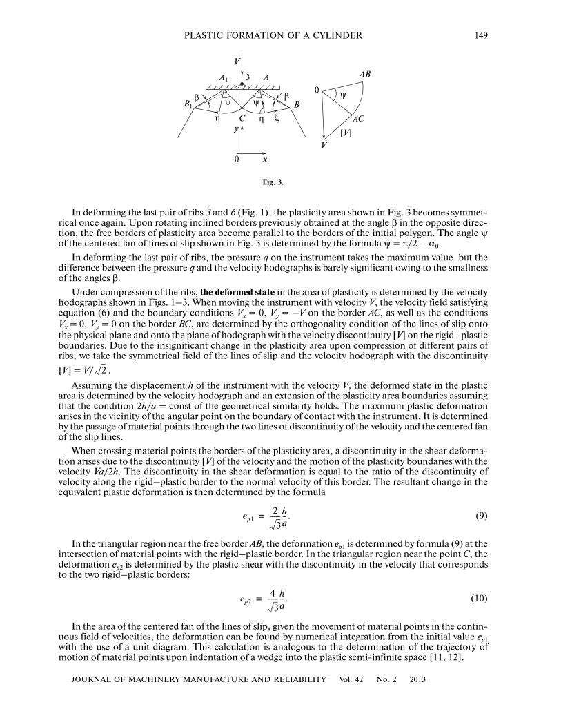
In deforming the last pair of ribs 3 and 6 (Fig. 1), the plasticity area shown in Fig. 3 becomes symmet�rical once again. Upon rotating inclined borders previously obtained at the angle β in the opposite direc�tion, the free borders of plasticity area become parallel to the borders of the initial polygon. The angle ψof the centered fan of lines of slip shown in Fig. 3 is determined by the formula ψ = π/2 – α0.
In deforming the last pair of ribs, the pressure q on the instrument takes the maximum value, but thedifference between the pressure q and the velocity hodographs is barely significant owing to the smallnessof the angles β.
Under compression of the ribs, the deformed state in the area of plasticity is determined by the velocityhodographs shown in Figs. 1–3. When moving the instrument with velocity V, the velocity field satisfyingequation (6) and the boundary conditions Vx = 0, Vy = –V on the border AC, as well as the conditionsVx = 0, Vy = 0 on the border BC, are determined by the orthogonality condition of the lines of slip ontothe physical plane and onto the plane of hodograph with the velocity discontinuity [V] on the rigid–plasticboundaries. Due to the insignificant change in the plasticity area upon compression of different pairs ofribs, we take the symmetrical field of the lines of slip and the velocity hodograph with the discontinuity
[V] = V/ .
Assuming the displacement h of the instrument with the velocity V, the deformed state in the plasticarea is determined by the velocity hodograph and an extension of the plasticity area boundaries assumingthat the condition 2h/a = const of the geometrical similarity holds. The maximum plastic deformationarises in the vicinity of the angular point on the boundary of contact with the instrument. It is determinedby the passage of material points through the two lines of discontinuity of the velocity and the centered fanof the slip lines.
When crossing material points the borders of the plasticity area, a discontinuity in the shear deforma�tion arises due to the discontinuity [V] of the velocity and the motion of the plasticity boundaries with thevelocity Va/2h. The discontinuity in the shear deformation is equal to the ratio of the discontinuity ofvelocity along the rigid–plastic border to the normal velocity of this border. The resultant change in theequivalent plastic deformation is then determined by the formula
(9)
In the triangular region near the free border AB, the deformation ep1 is determined by formula (9) at theintersection of material points with the rigid–plastic border. In the triangular region near the point C, thedeformation ep2 is determined by the plastic shear with the discontinuity in the velocity that correspondsto the two rigid–plastic borders:
(10)
In the area of the centered fan of the lines of slip, given the movement of material points in the contin�uous field of velocities, the deformation can be found by numerical integration from the initial value ep1with the use of a unit diagram. This calculation is analogous to the determination of the trajectory ofmotion of material points upon indentation of a wedge into the plastic semi�infinite space [11, 12].
2
ep12
3�����h
a�� .=
ep24
3�����h
a�� .=
V
A1 A3
ψββ
B1 B
Cy
x0
AB
AС
V
[V]
ψ
η ξη
0ψ
Fig. 3.

150
JOURNAL OF MACHINERY MANUFACTURE AND RELIABILITY Vol. 42 No. 2 2013
NEPERSHIN
The average plastic deformation in the area of the centered fan of the lines of slip can be obtained byintegrating the intensity of the shear deformation rate Γ that was reported in [10]
(11)
where ρ is the distance of the point to the center A of the fan of the lines of slip.The average deformation rate in the area of this fan is determined by integrating the distribution of the
deformation rate (11) in polar coordinates 0 ≤ ρ ≤ a/ , 0 ≤ θ ≤ ψ
(12)
From (12) we find the increment of the average deformation in the centered field of the lines of slip forthe time h/V corresponding to the displacement h of the instrument
(13)
The average plastic deformation ep3 on the border of contact of the ingot with the instrument isobtained from (10) and (13)
(14)
After the first cycle of compression of the ribs of the ingot, plastic deformation doubles near the freeborders. When passing material points through the centered fan of the lines of slip, the inhomogeneousdistribution of deformations leads to an increase in the plastic deformation from ep2 up to ep3 on theboundary of contact, and on the free borders of a polygon with the same length a of the side. After the firstcycle of compression of the ribs, an inhomogeneous distribution of plastic deformations is formed in the
surface layer with thickness a/ .During the subsequent compression cycles, deformations from the preceding cycle are summed with
the deformations ep2 and ep3 which are determined by formulas (10), (14) for the polygon with the doublednumber of the sides. This causes a growing plastic deformation in the surface layer with a decreasing thick�ness proportional to the ratio h/a.
The numerical examples. Here we present numerical results of calculations of the formation processesof cylindrical surfaces from the multifaceted prism, which are of interest for the operations of free forgingof hexagonal bars and rods from the square ingot. We used dimensionless variables in the calculations. Asa unit of length, we took the cross�sectional side a0 = 1 of the initial specimen, and as a unit of stress—theyield stress 2k = 1.
We took N0 = 6 and N0 = 4 for the hexagonal and square ingots, correspondingly. Figure 4 shows theinitial forms of hexagonal and square sections of the ingot, and the resultant forms shown by the cornerpoints of the polygons after five deformation cycles of all the ribs. As we can see, the resultant forms barelycoincide with the circle.
εp Γ/ 3, Γ1
2�����V
ρ��,= =
2
εp2
3�����V
a��.=
ep2
3�����h
a��.=
ep3 2 3h/a.=
2
y
x0
y
x0
Fig. 4.

JOURNAL OF MACHINERY MANUFACTURE AND RELIABILITY Vol. 42 No. 2 2013
PLASTIC FORMATION OF A CYLINDER 151
Tables 1, 2 show the dimensionless values of a, h, q, the force P, and the radii R, r of inscribed and cir�cumscribed circles after six deformation cycles of the ribs corresponding to the square (S = 1, R* = 0.5642)and hexagon (S = 2.598, R* = 0.9094) ingots, respectively. With an increasing number of cycles of plasticdeformation of the ribs of the ingot, the side length of the polygon (a), the compression of the rib (h), andthe force P tend to zero. The pressure q tends to 1 + π/2, while the radii R and r approach R*.
Figures 5 and 6 show the distributions of an accumulated plastic deformation ep over the thicknessof the plastically deformed layer for the six cycles of compression of the ribs of the ingots with the square
and hexagonal cross�sections, respectively. Since the depth a/ of the plasticity area decreases after2
Table 2. Deformation of an ingot with the hexahedral cross�section
Cycle number a × 100 h × 100 q P × 100 R × 10 r × 10
1 48.17 10.11 2.013 96.97 9.306 8.989
2 23.88 2.382 2.292 54.74 9.146 9.068
3 11.91 0.587 2.432 28.97 9.107 9.087
4 5.953 0.146 2.501 14.89 9.097 9.092
5 2.976 0.036 2.536 7.547 9.095 9.094
6 1.488 0.009 2.553 3.799 9.094 9.094
2.0
1.5
1.0
0.5
ep
0.1 0.2 0.3hp
1.0
0.5
ep
0.1 0.2 0.3 hp0
Fig. 5. Fig. 6.
Table 1. Deformation of an ingot with square cross�section
Cycle number a × 100 h × 100 q P × 100 R × 10 r × 10
1 45.51 15.78 1.731 78.78 5.946 5.493
2 22.30 3.406 2.153 48.01 5.715 5.605
3 11.10 0.824 2.362 26.21 5.660 5.633
4 5.541 0.204 2.466 13.67 5.646 5.640
5 2.770 0.050 2.519 6.976 5.643 5.641
6 1.385 0.013 2.545 3.524 5.642 5.642

152
JOURNAL OF MACHINERY MANUFACTURE AND RELIABILITY Vol. 42 No. 2 2013
NEPERSHIN
each cycle of compression, the plastic deformation is summed in the plastic layer that decreases inthickness with an increase in the plastic deformation towards the surface of the ingot. The surface defor�mation of the ingot tends to the finite value due to a decrease in the plastic deformation proportional toh/a. The corresponding value of the deformation depends on the initial shape of the ingot and dimin�ishes upon an increase in the number of faces N0 provided there is an equal number of cycles of com�pression of all the ribs.
CONCLUSIONS
As follows from the analysis of stress�deformed state, it is possible to obtain the round form of thecross�section of an ingot with high precision by means of cyclic plastic compression of ribs using a flatinstrument, provided there is exact control of the movement of the instrument and the angles of rotationof the ingot around the axis using the forging machines with the program control.
The calculation model makes it possible to obtain the distribution of the accumulated plastic deforma�tion in the surface layer of the ingot depending on the initial form of the cross�section and the number ofthe cycles of deformation of the ribs. An ideally plastic model demonstrates a abrupt increase in the plasticdeformation on the boundary of the plasticity area. In real processes, the transition to the intense plasticdeformation proceeds by the displacement with the finite width of the band of slippage with small defor�mations during the transition to the elastic area.
REFERENCES1. Mashinostroenie. Entsiklopediya (Machinery Manufacturing. Encyclopedia), vol. 3, part 2: Tekhnologiya zago�
tovitel’nykh proizvodstv (Technology of Blank Production), Moscow: Mashinostroenie, 1996.2. Ishlinskii, A.Yu. and Ivlev, D.D., Matematicheskaya teoriya plastichnosti (Mathematical Theory of Plasticity),
Moscow: Fizmatlit, 2001.3. Sokolovskii, V.V., Teoriya plastichnosti (The Theory of Plasticity), Moscow: Vysshaya shkola, 1969.4. Nepershin, R.I., Indentation of a smooth spherical die into a perfectly plastic half�space, Dokl. Phys., 2003,
vol. 48, no. 4, pp. 186–190.5. Ivlev, D.D., Ishlinskii, A.Yu., and Nepershin, R.I., Pyramid indentation into an ideal plastic half�space, Dokl.
Ross. Akad. Nauk, 2002, vol. 385, no. 6, pp. 766–769.6. Ivlev, D.D., Ishlinskii, A.Yu., and Nepershin, R.I., Pyramid indentation into an ideal plastic half�space, Dokl.
Phys., 2002, vol. 47, no. 8, pp. 630–633.7. Ivlev, D.D., Ishlinskii, A.Yu., and Nepershin, R.I., Pyramid indentation into an ideal plastic half�space, Izv.
Ross. Akad. Nauk. Mekhan. Tverd. Tela, 2002, no. 4, pp. 57–62.8. Ivlev, D.D., Ishlinskii, A.Yu., and Nepershin, R.I., Smashing of perfectly plastic pyramid by a flat die, Dokl.
Ross. Akad. Nauk, 2003, vol. 391, no. 3, pp. 337–339.9. Ivlev, D.D., Ishlinskii, A.Yu., and Nepershin, R.I., On the Compression of a Perfectly Plastic Pyramid by Flat
Die, Dokl. Phys., 2003, vol. 48, no. 7, pp. 382–384.10. Ivlev, D.D., Maksimova, L.A., Nepershin, R.I., et al., Predel’noe sostoyanie deformirovannykh tel i gornykh porod
(Limit State of Deformed Solids and Rocks), Moscow: Fizmatlit, 2008.11. Hill, R., Mathematical Theory of Plasticity, Oxford: Claredon Press, 1950.12. Tomlenov, A.D., Teoriya plasticheskogo deformirovaniya metallov (The Theory of Metals Plastic Deformation),
Moscow: Metallurgiya, 1972.