plastic mulch layer owners manuals3.amazonaws.com/bcs-america/manuals/et-mulch-layer...plastic mulch...
TRANSCRIPT
PLASTIC MULCH LAYER OWNERS MANUAL Congratulations on your purchase of a Plastic Mulch Layer implement to fit your BCS tractor. The 4-foot model is designed to lay plastic mulch on a flat surface and bury the edges of the mulch to hold it down during the growing season. It can also lay plastic mulch over a 30'' wide raised bed, provided it's not more than 6'' tall and can bury the edges at the base of the bed. The plastic mulch is typically removed from the soil by hand at the end of the growing season, since it is not durable enough for a second season.2400-foot rolls of mulch are recommended. ** NOTE: Depending on soil type & tractor size, it may be necessary to equip your BCS tractor with Wheel Weights for extra traction! ** A minimum of 5''x12'' wheels and 16” axle extensions are required on the tractor to allow the tractor to “straddle” the bed.
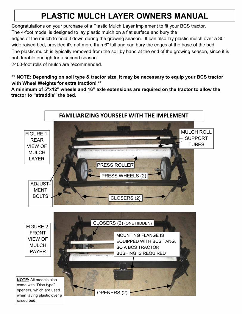
OPENERS (2)
MOUNTING FLANGE IS EQUIPPED WITH BCS TANG, SO A BCS TRACTOR BUSHING IS REQUIRED
FIGURE 2. FRONT
VIEW OF MULCH PAYER
FAMILIARIZING YOURSELF WITH THE IMPLEMENT
FIGURE 1. REAR
VIEW OF MULCHLAYER
CLOSERS (2)
PRESS WHEELS (2)
PRESS ROLLER
MULCH ROLL SUPPORT
TUBES
ADJUST-MENT BOLTS
CLOSERS (2) (ONE HIDDEN)
NOTE: All models also come with “Disc-type” openers, which are used when laying plastic over a raised bed.

FIGURE 3. SIDE VIEW OF MULCH LAYER
OPENER CLOSER
PRESS WHEEL
MULCH ROLL SUPPORT
TUBES
PRESS ROLLER
The basic premise of how this implement works is as follows: The plastic mulch roll sits on top of the SUPPORT TUBES, and the mulch is threaded down between the tubes (see Figure 4) and under the front of the PRESS ROLLER (see Figure 5). It does not matter which way the roll turns. A few feet of mulch is pulled out under the PRESS ROLLER to trail behind the layer; it can be anchored down with large “sod staples” or with heavy rocks, etc. As the implement is pulled along by the tractor, the OPENERS will open furrows in the soil by rolling the soil out-wards (see Figure 6). The PRESS WHEELS push the edges of the mulch down into the furrows created by the OPENERS (see Figure 7), while the PRESS ROLLER rolls the mulch out flat in between the press wheels. The CLOSERS then push the soil back in to fill the furrows and cover the edges of the plastic mulch (see Figure 8).
The OPENERS, PRESS WHEELS, and CLOSERS are adjustable (see Figure 9), while the PRESS ROLLER is fixed to the frame. Therefore, the PRESS ROLLER is the “fixed point” that everything else must be adjusted to accommodate. Adjustments on the various parts can vary greatly due to soil type & condition, and also by the users’ preference as to how deep the edges should be buried, how wide the finished exposed mulch will be, etc. There are no “factory pre-set adjustments”. When flat-laying plastic (NOT on a raised bed), between 32'' and 38'' will be exposed, dependingon adjustments. HAVING THE VARIOUS PARTS ADJUSTED EQUALLY ON BOTH SIDES OF THE LAYER IS IMPORTANT! For example, if one opener is set deeper then the other, or if one press-wheel is further out than the other, it will cause problems. A tape measurer or ruler is recommended, so you get the adjustments pretty close to matching on both sides. See the following photos for further clarification:
NOTE: 4-foot models also come with “Disc-type” openers, which are used when laying plastic over a raised bed.

FIGURE 4. MULCH BEING
THREADED THROUGH SUPPORT
ROLLERS AS ROLL IS SET INTO PLACE
FIGURE 5. MULCH DIRECTED UNDER PRESS ROLLER
FIGURE 6. OPENER MAKING FURROW
FIGURE 7. PRESS WHEEL PUSHING MULCH INTO FUR-ROW
FIGURE 8. CLOSER CLOS-ING FURROW AND COVER-ING EDGE OF MULCH
FIGURE 9. TYPICAL LOCKING BOLT FOR ADJUSTING VARIOUS PARTS. (A SHORT SECTION OF PIPE OR A PLI-ERS CAN BE USED FOR EXTRA LEVER-AGE, IF NEEDED.)
REFERENCE: FRONT OF LAYER REFERENCE: FRONT OF LAYER

FIGURE 10. PRESS WHEEL WIDTH CAN BE ADJUSTED BY LOOS-ENING THE 2 LOCKING COLLARS AND SLID-ING THE WHEEL IN OR OUT ON THE AXLES. (REQUIRES AN ALLEN WRENCH)
FIGURE 11. THE OPENERS CAN BE AD-JUSTED 3 WAYS: DEPTH, WIDTH, AND ANGLE. DISC-TYPE OPENERSARE ONLY FOR RAISED GARDEN BEDS.
FIGURE 12. YOU WANT THE OPENERS, PRESS WHEELS, AND CLOSERS ARRANGED MORE OR LESS “IN-LINE”, SINCE THE PRESS WHEELS HAVE TO FOLLOW IN THE FURROWS CREATED BY THE OPENERS, AND THE CLOS-ERS HAVE TO PUSH THE SOIL INTO THE FURROWS. NOTE: CAREFUL THAT YOU DO NOT ADJUST THE CLOS-ERS TOO CLOSE TO THE EDGE OF THE MULCH...THE MULCH MIGHT GET TORN. (THIS IS ON THE “CLOSE” SIDE IN THIS PICTURE...YOU MIGHT WANT MORE CLEARANCE)
“IMAGINARY” LINE
FRONT TIP OF OPENER
PRESS WHEEL
INNER EDGE OF CLOSER
MAINTENANCE OF MULCH LAYER. SINCE THIS IS A VERY SIMPLE IMPLEMENT, IT DOES NOT REQUIRE MUCH MAINTENANCE. AT LEAST ONCE PER YEAR, WE RECOMMEND AP-PLYING SOME SPRAY-LUBRICANT (FLUID FILM™, TEFLON™, ETC.) WHERE PARTS RO-TATE, SUCH AS INSIDE THE MULCH ROLL SUPPORT TUBES, THE AXLE OF THE PRESS ROLLER, THE MANY ADJUSTMENT BOLTS, ETC. STORING THE IMPLEMENT OUT OF THE WEATHER IS RECOMMENDED, TO AVOID RUST AND PROLONG IMPLEMENT LIFE.

DRIP-TAPE LAYER KIT INSTALLATION AND USE Since moisture cannot penetrate through plastic mulch, many farmers use Drip-Tape, installed underneath the plastic, to provide water to plants. This Drip-Tape can be applied in two ways: 1. It can be laid down manually BEFORE the plastic mulch is laid down, or: 2. It can be applied at the same time the mulch is laid down, by installing a “Drip-Tape Layer Kit” on the mulch layer. The first method is less cost outlay, because the kit does not have to be purchased, but takes more time, since the drip-tape is laid separately from the plastic. Method #2 is a faster, all-in-one operation. For those farmers using the latter method, following are instructions for proper installa-tion and use of this kit.
FIGURE A. This shows a 1000-foot roll of drip tape installed on the Drip-Tape Layer Kit. The standard Kit is made to accommodate only 1000-foot rolls of drip-tape (This size roll available from the mulch-layer sup-plier). HOWEVER, a longer axle and an additional support leg (to support the other end of the axle) can be pur-chased, so up to 3000-foot rolls of drip tape (not typically available from mulch-layer supplier; contact an irri-gation supplier) can be mounted. (NOTE: This larger roll would in-crease the weight of the implement, so a front-weight may need to be mounted to the walk-behind tractor engine for proper machine balance)
DRIP-TAPE ROLL
DRIP-ROLL SUPPORT
CLAMP (MOUNTED TO BACK RAIL OF MULCH LAYER
FRAME)
DRIP-TAPE IS ROUTED OVER THE TOP OF PLASTIC MULCH ROLL, THEN THROUGH “SHOVEL” (SEE FIGURE B) AND UNDER PLASTIC MULCH ON GROUND. (MULCH NOT PULLED OFF ROLL IN THIS PICTURE...IF IT WERE, IT WOULD BE COV-ERING THE DRIP-TAPE) AXLE
FIGURE B. DRIP-TAPE ROUTED OVER TOP OF PLASTIC MULCH ROLL OND DOWN THROUGH TUBE IN “SHOVEL”. SHOVEL CAN BE ADJUSTED IN DEPTH DE-PENDING ON FARMER’S WISHES...CAN LAY DRIP-TAPE ON TOP OF THE GROUND, OR BURY IT SLIGHTLY. THE SHOVEL ASSEMBLY CAN BE ADJUSTED LEFT-TO-RIGHT ANY-WHERE ON THE FRONT FRAME RAIL, BUT OBVIOUSLY IT WILL DO BEST NEAR THE CENTER, FOR EVEN WATER APPLICATION.

FIGURE C. PROPER AS-SEMBLY ODER FOR DRIP-TAPE ROLL “FRICTION” WASHERS & SPRING, TO KEEP SOME TENSION ON ROLL SO IT DOES NOT “FREEWHEEL”. FIRST IS PLASTIC FITTING, THEN LARGE WASHER, THEN SPRING, THEN LOCKING COLLAR. FARMER CAN ADJUST TENSION AS THEY SEE FIT, BY COM-RESSING SPRING MORE OR LESS BEFORE TIGHT-ENING COLLAR.
FIGURE D. PROPERLY INSTALLED FRICTION WASHERS & SPRING, HOLDING DRIP-TAPE ROLL IN PLACE ON AXLE. NOTE: IF LONGER AXLE & EXTRA SUPPORT LEG ARE USED TO ACCOMMODATE A LAR-GER ROLL OF DRIP-TAPE, A “STOP” ON THE FAR SIDE OF THE ROLL MAY HAVE TO BE IMPROVISED (YOU DO NOT NEED A FRICTION WASHER & SPRING ON BOTH SIDES)...A SHORT PIECE OF PVC PIPE COULD BE USED FOR THIS.
TO THE RIGHT IS A PICTURE OF A BCS TRACTOR WITH A PLASTIC MULCH LAYER MOUNTED TO IT. (THIS TRACTOR IS ALSO EQUIPPED WITH 16” AXLE AXTENSIONS, SO THAT WHEEL TRACKS ARE OUTSIDE OF THE FINISHED MULCH WIDTH, AND THERE WILL BE NO TRACKS UNDER THE PLASTIC.) THE TRACTOR HANDLEBARS ARE OFFSET TO THE SIDE, SO THE OPERATOR DOES NOT HAVE TO WALK ON THE PLASTIC. IT IS RECOMMENDED TO MAKE SOME “TEST RUNS” WITH THIS IMPLEMENT, IN ORDER TO GET THE AD-JUSTMENTS RIGHT FOR YOUR SOIL CONDITIONS. For parts, service, or other questions, contact:
BCS AMERICA LLC 800-543-1040 [email protected] Instructions by Earth Tools, Inc. www.EarthToolsBCS.com