plastics for aircraft homebuilding -...
TRANSCRIPT
plastics for
Plastic Foams WinFavorable AttentionAt 1974 EAA Fly-In
By Val Wright (EAA 81831)516 Wrightwood TerraceLibertyville, Illinois 60048
E(AA HOMEBUILT ENTHUSIASTS, there's probablya plastic foam in your future — several types of them, infact! This could mean, in many cases, that your "bird"will be lighter, give you improved performance, and canbe completed in only a fraction of the building time re-quired with conventional materials.
These conclusions are hard to avoid after witnessingthe growing application of rigid plastic foams at the 1974Oshkosh Fly-In, and attending several forums at whichthese materials were favorably mentioned by authorita-tive builders.
With more and more EAA members becoming inter-ested in cellular plastics and eager to work with them,it's important at this time that they familiarize them-selves with the most widely used types. As a starter, we'reincluding in this article a quick reference chart coveringseveral basic varieties of rigid plastic foams currentlyutilized in the construction of sailplanes and light pow-ered aircraft. SPORT AVIATION also plans, in forthcom-ing issues, to publish additional articles covering spe-cific types of plastic foams and how EAA builders areusing them.
(Incidentally, one of the best general informationsources we've seen on rigid plastic foams is a 24-pagepaperbound booklet by Lou Sauve entitled "The Use ofSandwich Structures in Airplane Construction". It'savailable at $1.00 from Aircraft Spruce and Specialty Co.,Fullerton, Calif.)
But, getting back to Oshkosh '74:
KEN RAND'S NEW KR-2Without question, Ken Rand's new two-place KR-2,
powered by a VW-1600 engine, was one of the star attrac-tions at this year's Fly-In. Following the same generallines as Ken's KR-1, the entire KR-2 airframe incorpor-ates a urethane foam/Dynel type construction. (Polysty-rene foam, rather than urethane, was used in the originalKR-1.) The new aircraft has an empty, weight of only 420lbs. and gross weight of 800 lbs. With a length of 14 ft.4 in. and span of 20 ft. 2 in., it cruises at 140 mph and hasa top speed of 150 mph, according to published specifi-cations made available at Oshkosh.
One of the principal virtues of plastic foam construc-tion — ease of repair — was convincingly demonstratedto Fly-In attendees when Rand and his associates hadto make on-the-spot repairs before the KR-2 could beflown at Oshkosh. En route from the West Coast, fuelproblems necessitated an unscheduled landing in Kansasduring which the aircraft struck a ditch, damaging theretractable aluminum landing gear and punching holes30 DECEMBER 1974
Si.3
I
homebuilding
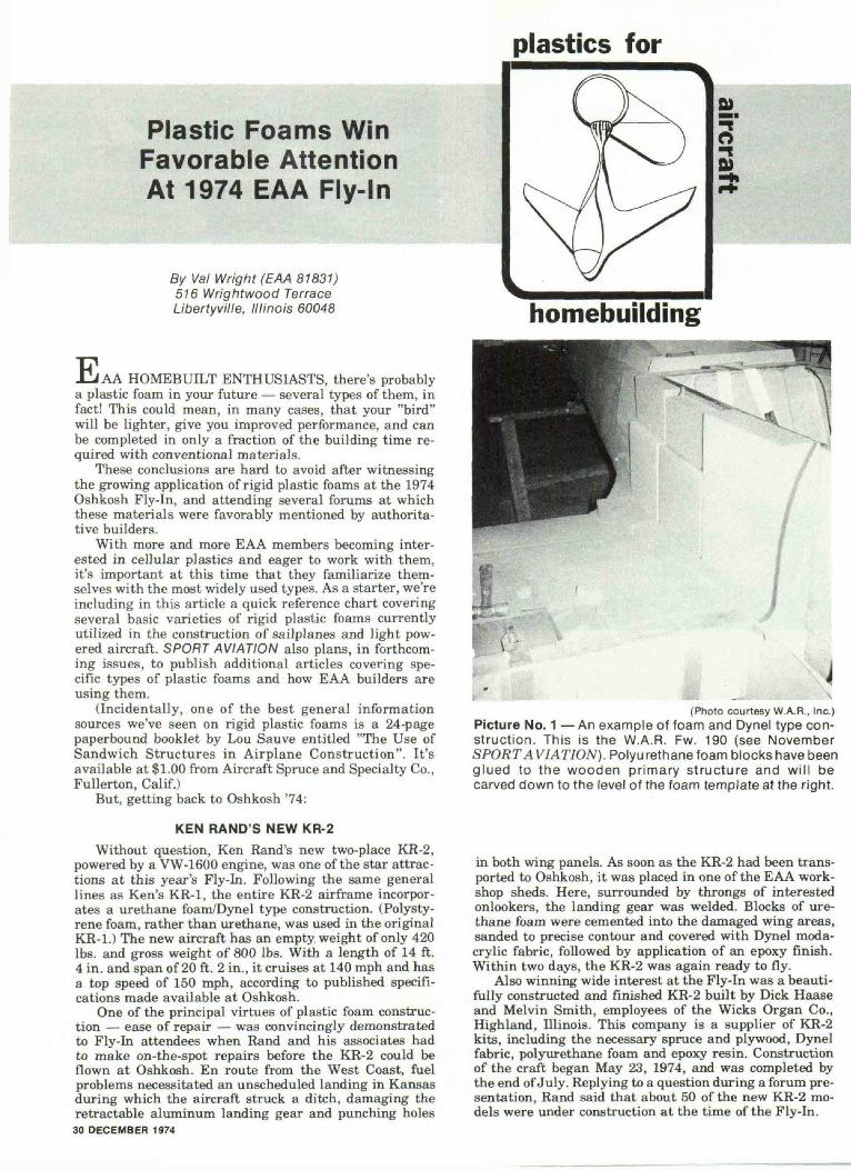
(Photo courtesy W.A.R., Inc.)Picture No. 1 — An example of foam and Dynel type con-struction. This is the W.A.R. Fw. 190 (see NovemberSPORT AVIATION). Polyurethane foam blocks have beenglued to the wooden primary structure and will becarved down to the level of the foam template at the right.
in both wing panels. As soon as the KR-2 had been trans-ported to Oshkosh, it was placed in one of the EAA work-shop sheds. Here, surrounded by throngs of interestedonlookers, the landing gear was welded. Blocks of ure-thane foam were cemented into the damaged wing areas,sanded to precise contour and covered with Dynel moda-crylic fabric, followed by application of an epoxy finish.Within two days, the KR-2 was again ready to fly.
Also winning wide interest at the Fly-In was a beauti-fully constructed and finished KR-2 built by Dick Haaseand Melvin Smith, employees of the Wicks Organ Co.,Highland, Illinois. This company is a supplier of KR-2kits, including the necessary spruce and plywood, Dynelfabric, polyurethane foam and epoxy resin. Constructionof the craft began May 23, 1974, and was completed bythe end of July. Replying to a question during a forum pre-sentation, Rand said that about 50 of the new KR-2 mo-dels were under construction at the time of the Fly-In.
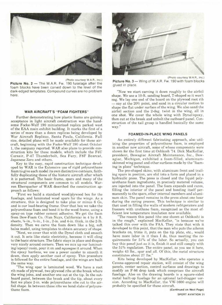
(Photo courtesy W A R . . Inc )Picture No. 2 — The W.A.R. Fw. 190 fuselage after thefoam blocks have been carved down to the level of thedark-edged templates. Compound curves are no problemhere.
WAR AIRCRAFT'S "FOAM FIGHTERS"Further demonstrating how plastic foams are gaining
acceptance in light aircraft construction was the hand-some Focke-Wulf 190 miniaturized replica parked westof the EAA main exhibit building. It marks the first of aseries of more than a dozen replicas being developed byWar Aircraft Replicas, Santa Paula, California. Fullsize, detailed plans will be made available for these air-craft, beginning with the Focke-Wulf 190 about October1, the company reported. WAR also plans to provide con-struction kits for these models, which include the F4UCorsair, P-47 Thunderbolt, Sea Fury, F8F Bearcat,Japanese Zero and others.
Key to the easy, rapid construction technique devel-oped by WAR is the Extensive use of rigid polyurethanefoam to give each model its own distinctive contours, faith-fully duplicating those of the historic aircraft after whichit is patterned. The basic frame, spars and many of thestructural components are common to all models. War-ren Eberspacher of WAR described the construction ap-proach as follows:
"First we build a standard wood/plywood box for thefuselage, and laminated wood spars for the wings. As astructure, this is designed to take plus or minus 6 GS,and is our load-bearing frame. Over that box we take thepolyurethane foam and bond it to the wood frame, using aspray-on type rubber cement adhesive. We get the foamfrom Dew-Foam Co. (Van Nuys, California) in 4 by 8 ft.sheets, '/4-in., V4-in., 1-in., 2-in. and 4-in. thick, in the 2-lb.density. Then we carve the foam down like a big, softbalsa model, using templates to obtain accuracy of shape.
"Next, we cover that with the Dynel cloth and smoothit out. It acts like static electricity, because it will clingto the basic structure. The fabric stays in place and drapesvery nicely around corners. Then we mix up our laminat-ing (epoxy) resin, pour it on and squeegee it around. Whenthe epoxy hardens, we use a power sander to smooth itdown, then apply another coat of epoxy. This procedureis followed for the entire fuselage, and the wings are builtthe same way.
"The wing spar is laminated wood. We have a rootrib made of plywood, two plywood ribs at the break wherethe wing joins, and another one out at the tip. In the out-board panel, between the break and the tip, about everyfoot we place 2-in. wide polyurethane ribs cut to the air-foil shape. In between these ribs we bond slabs of polyure-thane foam.
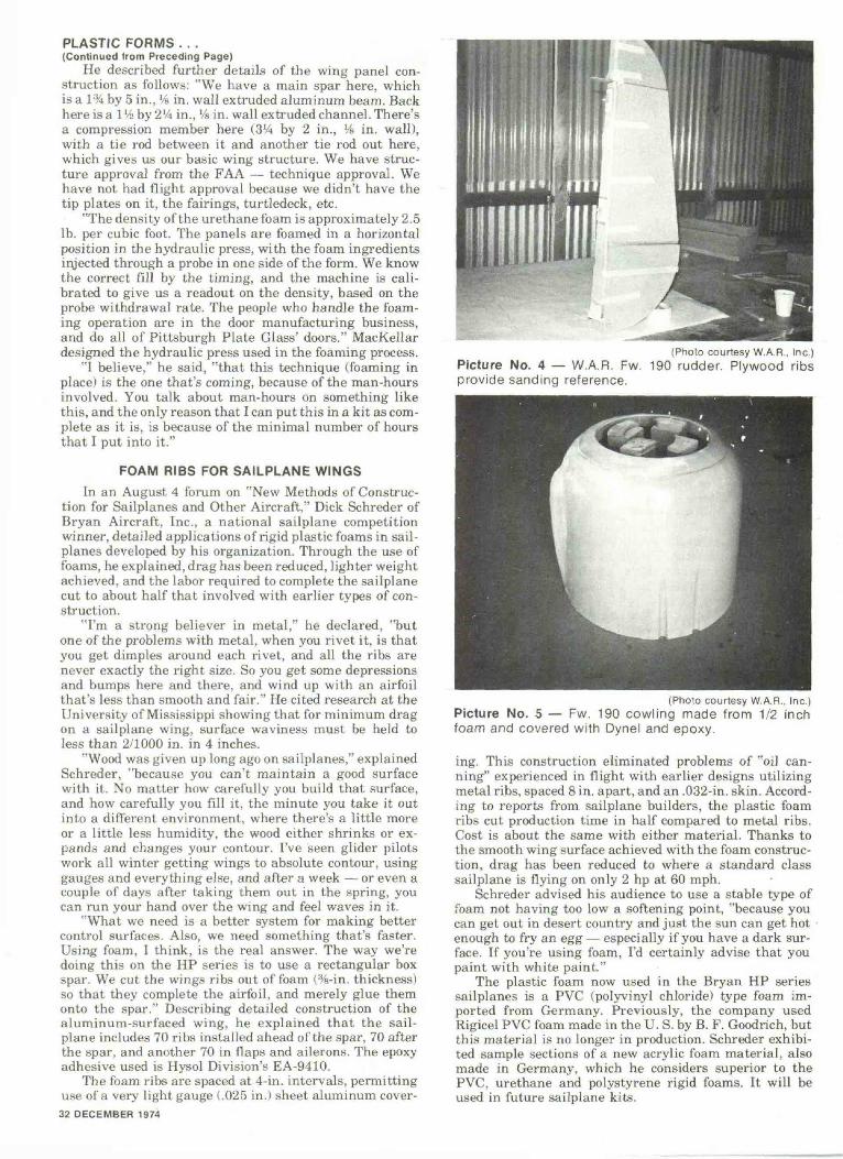
(Photo courtesy W.A.R.. Inc.)Picture No. 3 —Wing of W.A.R. Fw. 190 with foam blocksglued In place.
"Now we start carving it down roughly to the airfoilshape. We use a 10-ft. sanding board, T-shaped so it won'tsag. We lay one end of the board on the plywood root rib— say at the 207( point, and sand in a circular motion toshape the flat under surface of the wing. We also sand theairfoil section and the 2-deg. twist in the wing, all inone shot. We cover the whole wing with Dynel/epoxy,then cut at the break and unbolt the outboard panel. Con-struction of the tail group is handled basically the sameway."
FOAMED-IN-PLACE WING PANELSAn entirely different fabricating approach, also util-
izing the properties of polyurethane foam, is employedin another new aircraft, some of whose components wereshown for the first time at Oshkosh 74. Dick MacKellar,president, Dowagiac Aircraft Maintenance, Inc., Dow-agiac, Michigan, exhibited a foam-fil led, a luminum-skinned wing panel and other surfaces made by the "foam-ing in place" technique.
The pre-shaped skins, with aluminum front and trail-ing spars in position, are slid into a form and placed in ahydraulic press. The press is closed and the liquid poly-urethane foam ingredients, in precisely metered volume,are injected into the panel. The foam expands and cures,filling the interior of the panel and bonding itself per-manently to the spars, other internal members and alumi-num skin. The panel remains in the press about one hourduring the curing process. This technique is similar tothat used in filling the walls of modern refrigerators andfreezers with urethane foam, recognized as the most ef-ficient low temperature insulation now available.
"The reason this panel (the one shown at Oshkosh) isin the rough," explained MacKellar, "is because we'vetalked this over with the FAA. They state that with itdeveloped to this point, that the man who puts the aileronbrackets on, trims it, puts on the tip plate, etc., wouldhave more labor in it than I do, thus meeting the re-quirements for 51% of the labor. So actually, you canbuy this panel just as it is, finish it and still comply withthe 51% regulation. The entire panel, as you see it here,weighs 43 lbs., spar and all. Of this, the metal structureconstitutes about 27 lbs."
Kits being developed by MacKellar, who operates aCessna-approved repair station, will consist of the wingpanels, center section, control surfaces and drawings tomodify an F-86 drop tank which comprises the aircraftfuselage. Also on the drawing boards is a square-sidedmetal built-up fuselage for an optional tail-dragger ver-sion. According to MacKellar, the VW-1600 engine willprobably be specified for these aircraft.
(Continued on Next Page)SPORT AVIATION 31
PLASTIC FORMS . . .(Continued from Preceding Page)
He described further details of the wing panel con-struction as follows: "We have a main spar here, whichis a 1% by 5 in., Vs in. wall extruded aluminum beam. Backhere is a l'/2 by 2'/4 in., Vs in. wall extruded channel. There'sa compression member here (3% by 2 in., Vu in. wall),with a tie rod between it and another tie rod out here,which gives us our basic wing structure. We have struc-ture approval from the FAA — technique approval. Wehave not had flight approval because we didn't have thetip plates on it, the fairings, turtledeck, etc.
"The density of the urethane foam is approximately 2.5lb. per cubic foot. The panels are foamed in a horizontalposition in the hydraulic press, with the foam ingredientsinjected through a probe in one side of the form. We knowthe correct fill by the timing, and the machine is cali-brated to give us a readout on the density, based on theprobe withdrawal rate. The people who handle the foam-ing operation are in the door manufacturing business,and do all of Pittsburgh Plate Glass' doors." MacKellardesigned the hydraulic press used in the foaming process.
"I believe," he said, "that this technique (foaming inplace) is the one that's coming, because of the man-hoursinvolved. You talk about man-hours on something likethis, and the only reason that I can put this in a kit as com-plete as it is, is because of the minimal number of hoursthat I put into it."
FOAM RIBS FOR SAILPLANE WINGSIn an August 4 forum on "New Methods of Construc-
tion for Sailplanes and Other Aircraft," Dick Schreder ofBryan Aircraft, Inc., a national sailplane competitionwinner, detailed applications of rigid plastic foams in sail-planes developed by his organization. Through the use offoams, he explained, drag has been reduced, lighter weightachieved, and the labor required to complete the sailplanecut to about half that involved with earlier types of con-struction.
"I'm a strong believer in metal," he declared, "butone of the problems with metal, when you rivet it, is thatyou get dimples around each rivet, and all the ribs arenever exactly the right size. So you get some depressionsand bumps here and there, and wind up with an airfoilthat's less than smooth and fair." He cited research at theUniversity of Mississippi showing that for minimum dragon a sailplane wing, surface waviness must be held toless than 2/1000 in. in 4 inches.
"Wood was given up long ago on sailplanes," explainedSchreder, "because you can't maintain a good surfacewith it. No matter how carefully you build that surface,and how carefully you fill it, the minute you take it outinto a different environment, where there's a little moreor a little less humidity, the wood either shrinks or ex-pands and changes your contour. I've seen glider pilotswork all winter getting wings to absolute contour, usinggauges and everything else, and after a week — or even acouple of days after taking them out in the spring, youcan run your hand over the wing and feel waves in it.
"What we need is a better system for making bettercontrol surfaces. Also, we need something that's faster.Using foam, I think, is the real answer. The way we'redoing this on the HP series is to use a rectangular boxspar. We cut the wings ribs out of foam (%-in. thickness)so that they complete the airfoil, and merely glue themonto the spar." Describing detailed construction of thealuminum-surfaced wing, he explained that the sail-plane includes 70 ribs installed ahead of the spar, 70 afterthe spar, and another 70 in flaps and ailerons. The epoxyadhesive used is Hysol Division's EA-9410.
The foam ribs are spaced at 4-in. intervals, permittinguse of a very light gauge (.025 in.) sheet aluminum cover-32 DECEMBER 1974
(Photo courtesy W.A.R., Inc.)Picture No. 4 — W.A.R. Fw. 190 rudder. Plywood ribsprovide sanding reference.
(Photo courtesy W.A.R., Inc.)Picture No. 5 — Fw. 190 cowling made from 1/2 inchfoam and covered with Dynel and epoxy.
ing. This construction eliminated problems of "oil can-ning" experienced in flight with earlier designs utilizingmetal ribs, spaced 8 in. apart, and an .032-in. skin. Accord-ing to reports from sailplane builders, the plastic foamribs cut production time in half compared to metal ribs.Cost is about the same with either material. Thanks tothe smooth wing surface achieved with the foam construc-tion, drag has been reduced to where a standard classsailplane is flying on only 2 hp at 60 mph.
Schreder advised his audience to use a stable type offoam not having too low a softening point, "because youcan get out in desert country and just the sun can get hot •enough to fry an egg — especially if you have a dark sur-face. If you're using foam, I'd certainly advise that youpaint with white paint."
The plastic foam now used in the Bryan HP seriessailplanes is a PVC (polyvinyl chloride) type foam im-ported from Germany. Previously, the company usedRigicel PVC foam made in the U. S. by B. F. Goodrich, butthis material is no longer in production. Schreder exhibi-ted sample sections of a new acrylic foam material, alsomade in Germany, which he considers superior to thePVC, urethane and polystyrene rigid foams. It will beused in future sailplane kits.
The pure white acrylic foam has a fine, almost invisi-ble cell structure and is firmer and more rigid than theother foams in a comparable thickness and density. In athickness of % in., cost of the material was given as $1.50per sq. ft. Approximately 60 sq. ft. of the material is re-quired in the complete sailplane.
With the foam rib construction, said Schreder, expan-sion and contraction present no problem because the plas-tic material is sufficiently flexible to "come and go" withdimensional changes in the aluminum skin to which it isadhesively bonded. He stated that use of the PVC foamribs provides a 20 to 1 safety factor for the sailplanescovered in his presentation.
FOUR TYPES OF RIGID FOAMS USEDIN LIGHT AIRCRAFT CONSTRUCTION
Polystyrene(styrene)
Polyurethane(urethane)
Easilyfabricatedand sandedto shape
(Can also becut readilywith hot wire)
Polyvinyl chloride(PVC)
Acrylic
Importantfeatures
Lowest in cost & most widelyavailable. Less chemical re-sistant than others listed.Cannot be used with solventtype adhesives. Dissolved bygasoline or polyester resin.
Resistant to most chemicalsand fuels. Compatible witheither polyester or epoxy res-ins. Only foam of those listedwhich can also be foamed inplace by combining liquidingredients.
Used with good results insailplane wing construction.Excellent chemical resis-tance. Less available thanpolystyrene or polyurethane;no longer produced in U. S.
New type foam manufac-tured in Germany. Nearly in-visible cell structure. Out-standing strength and rigid-ity.
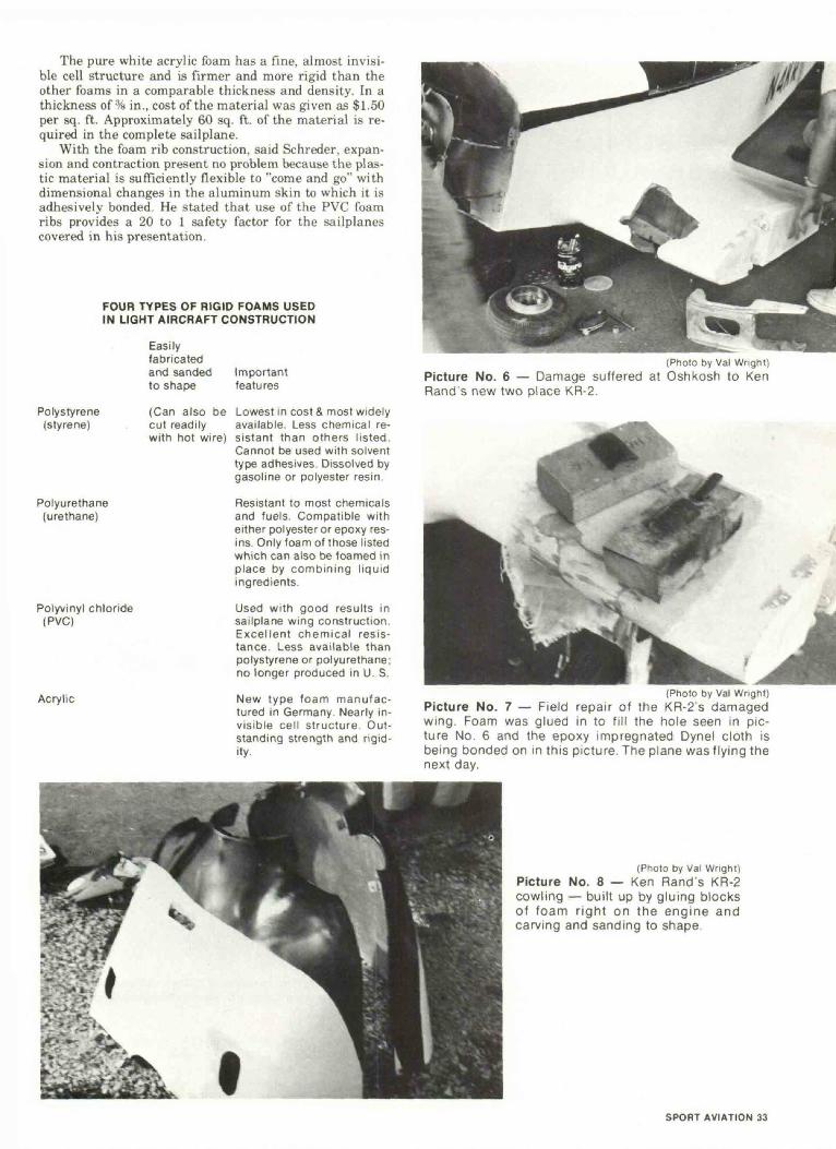
(Photo by Val Wright)Picture No. 6 — Damage suffered at Oshkosh to KenRand s new two place KR-2.
(Photo by Val Wright)Picture No. 7 — Field repair of the KR-2's damagedwing. Foam was glued in to fill the hole seen in pic-ture No. 6 and the epoxy impregnated Dynel cloth isbeing bonded on in this picture. The plane was flying thenext day.
(Photo by Val Wright)Picture No. 8 — Ken Rand's KR-2cowling — built up by gluing blocksof foam right on the engine andcarving and sanding to shape.
SPORT AVIATION 33