plastics industry blow molding pet compressors & … · include items such as plastic milk jugs...
TRANSCRIPT

Plastics Industry Blow Molding PET Compressors & DryersJ U N E 2 0 0 6
TM

FLOWS TO 20,000 SCFM • PRESSURE TO 1,000 PSIG • DEW POINTS TO -100°F • FILTRATION TO 0.0008 PPM W/W • WORLDWIDE DISTRIBUTION
High pressure HPET Series compressed air dryers and HF Series filters improve productivity and protect blowmolding and thermoforming
operations from damaging oil, water and particulate during the injection process. Since 1948, engineers from around
the world have specified energy-efficient Hankison products to reduce operating costs and keep their air systems clean and dry.
Trust your compressed air quality requirements to Hankison.
Telephone: 724.745.1555 Fax: 724.745.6040 Email: [email protected] www.hankisonintl.com
3
Focus Industry | PLASTICS BLOW MOLDING 0 6 / 0 6 | BEST PRACTICESCOMPRESSED AIR
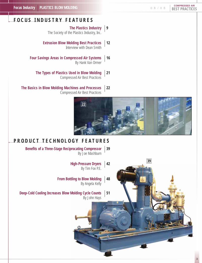
F O C U S I N D U S T R Y F E A T U R E SThe Plastics Industry | 9
The Society of the Plastics Industry, Inc.
Extrusion Blow Molding Best Practices | 12Interview with Dean Smith
Four Savings Areas in Compressed Air Systems | 16By Hank Van Ormer
The Types of Plastics Used in Blow Molding | 21Compressed Air Best Practices
The Basics in Blow Molding Machines and Processes | 22Compressed Air Best Practices
P R O D U C T T E C H N O L O G Y F E A T U R E SBenefits of a Three-Stage Reciprocating Compressor | 39
By Joe Mashburn
High-Pressure Dryers | 42By Tim Fox P.E.
From Bottling to Blow Molding | 48By Angela Kelly
Deep-Cold Cooling Increases Blow Molding Cycle Counts | 51By John Hays
22
39

5
Compressed Air Industry | ARTICLES 0 6 / 0 6 | BEST PRACTICESCOMPRESSED AIR
C O M P R E S S E D A I R I N D U S T R Y A R T I C L E SFrom the Editor | 7
Kaeser Compressors, Inc. | 25
SPX Dehydration & Process Filtration | 28
Tencarva Machinery | 30
Branding Corporations | 34By Rod Smith
Industry News | 35
28
25
30

6
BEST PRACTICES | 0 6 / 0 6 Focus Industry | PLASTICS BLOW MOLDINGCOMPRESSED AIR
C O M P R E S S E D A I R B E S T P R A C T I C E S M A G A Z I N Ew w w . a i r b e s t p r a c t i c e s . c o m
Advertising & Editorial: Rod [email protected]: 251-680-9154
Subscriptions & Administration: Patricia [email protected]: 251-510-2598
A Publication Of: Smith Onandia Communications L.L.C.161 Clubhouse CircleFairhope, AL 36532
Each drop of condensate in the com-
pressed air system involves risks with
a negative impact on product quality,
process reliability and down time of
machines or tools. These risks can ruin
cost accounting and profitability at any
time.
BEKO’s condensate technology provides
safety, reliability and economic viability.
With a technology that has proven
so successful on the world market for
condensate management and removal,
the more than one million installations
of BEKOMAT® Condensate Drains
speak for themselves. ÖWAMAT®
Oil/Water Separators, QWIKPURE®
and BEKOSPLIT® Emulsion Splitting
Systems set the industrial standard for
condensate treatment.
Reduce the risks to your cost accounting,
convince yourself of the BEKO competence.
Take your chance.
Do not hesitate to contact us for detailed
information.
BEKO TECHNOLOGIES CORP236 Raceway Drive, Suite 1 Mooresville, NC 28117 · USAPhone +1 (800) 235-6797Fax +1 (704) [email protected]
CONDENSATE KILLS
COST ACCOUNTING
Compressed Air Best Practices is published monthly by Smith Onandia Communications LLC., 161 Clubhouse Circle,Fairhope, AL, 36532. Phone (251) 510-2598. Publisher can not be held liable for non delivery due to circumstancesbeyond its control. No refunds. SUBSCRIPTIONS & REPRINTS: Annual rates for one subscription: U.S. $175; Canada$185; International $220. Reprints are available on a custom basis. Contact Patricia Smith for multiple-subscription discounts, reprint quotations and customer service at (251) 510-2598 or email: [email protected]. When available, extra copies of current issues are $20. Standard postage paid at 233 Jefferson Street, Greenfield Ohio 45123.Canadian and international distribution: IMEX International Mail Espress, 1842 Brummel Drive, Elk Grove Village IL60007. POSTMASTER: Send address changes to Compressed Air Best Practices, 161 Clubhouse Circle, Fairhope, AL36532. Printed in U.S.A.

7
Focus Industry | PLASTICS BLOW MOLDING
F R O M T H E E D I T O RA New JourneyROD SMITH
0 6 / 0 6 | BEST PRACTICESCOMPRESSED AIR
Thank you for reading the inaugural issue of
Compressed Air Best Practices Magazine and
beginning a new journey with us. The objective
of this monthly magazine is to assist plant
engineers, plant managers, and plant maintenance
managers with optimizing their compressed
air systems.
These “Best Practices” will be provided for specific industries in each
edition. Compressed air product manufacturers and distributors,
compressed air system consultants, and end users themselves have
vast amounts of knowledge, which we will make available to an
international readership base.
Compressed air, known as the “Fourth Utility,” plays an important
role in the capability of industry to manufacture efficiently. The
convenience and flexibility of compressed air makes it a very attractive
power source for countless manufacturing processes. Compressed air
products have also proven to be reliable and durable, ensuring minimal
down time and product rejections related to the compressed air system.
Managing the energy costs associated with compressed air remains an
area of tremendous opportunity for most manufacturing facilities.
“Lean Manufacturing” principles are not widespread as they relate
to compressed air systems. Measurement of efficiency, per product
manufactured, and kaizen events are opportunities for a large percentage
of compressed air systems. A significant portion of this magazine
is dedicated to providing industry with guidance in this area. Just as
important, information about how industry uses air will be provided
to compressed air industry professionals to help them better understand
the needs of specific applications.
I would like to thank my wife Patricia, who is my partner in business
and in life, for encouraging me to begin the journey to become an
entrepeneur and start Compressed Air Best Practices Magazine. The
support of so many people in the compressed air industry is inspiring
and motivating for me — and for this I thank you. The journey begins
with this edition, in cooperation with 8,500 plastics industry engineers
and 1,500 compressed air industry professionals. Together we strive
to help you make a difference in compressed air systems.
ROD SMITH
SUBSCRIBE NOW!C O M I N G E D I T I O N S !
Energy Efficiency, Printing, Hospitals, Food Processing,Concrete, Manufacturing Productivity
I D E A L F O R :INDUSTRY:
Plant Engineers, Plant Managers & Maintenance Managers
COMPRESSOR DISTRIBUTORS:Every Branch Location
MANUFACTURERS:Management, Sales, Marketing & Engineering
Rates: 12-month SubscriptionNumber of
Subscriptions 1-10 11-19 20-49 50+
U.S. $175.00 $160.00 $140.00 $130.00
Canada $185.00 $170.00 $150.00 $140.00
International $220.00 $205.00 $195.00 $180.00
3 W A Y S T O S U B S C R I B E :*
1.) Visit www.airbestpractices.comand use your Visa/Mastercard
2.) Email us at [email protected] mail your check.
3.) Mail your information and check to:Compressed Air Best Practices161 Clubhouse CircleFairhope, AL 36532
Checks should be made out to “Smith Onandia Communications, LLC ”. Questions call Patricia Smith: 251-510-2598.
*Information Required:
First Name:
Last Name:
Company Name:
Street: City:
State(Province): Zip Code:
Country: email:
Phone: Fax:

TRANSAIR® Pipe For Compressed AirAluminum and Stainless Steel, Available in 1/2" – 4" Pipe Size
USED IN A WIDE ARRAY OF
INDUSTRIES> Aerospace
> Food and Beverage> Automotive> Chemical
> Pulp and Paper> Marine
> Energy/Power> Textiles
> Wood Working> Pharmaceutical
> EASIER WORKING ON SITELightweight, easy to cut
pipe material
> SYSTEM QUICKLY READY FOR TEST AND USE
Immediate Start-up
INSTALLATION
REUSABLE> Removable and
interchangeable components> Immediate and easy layout modifications
SIMPLEINSTALLATION
> Aerospace> Food and Beverage
> Automotive> Chemical
> Pulp and Paper> Marine
> Energy/Power> Textiles
> Wood Working> Pharmaceutical
ENERGY
EFFICIENT> CLEAN AIR
Consistent high quality internal surface
> HIGH FLOW RATE PERFORMANCEFull flow connection and low friction
internal surface of the pipe
> OPTIMUM SEALINGCalibrated pipe diameter
SAFE> Non-flammable
Materials
> Conform to UL 94HB and UL94V-2
7205 E. Hampton Ave. Mesa, AZ 85209 Phone: 480-830-7764 www.transair-usa.com

9
Focus Industry | PLASTICS BLOW MOLDING
T H E P L A S T I C S I N D U S T R Y
0 6 / 0 6 | BEST PRACTICESCOMPRESSED AIR
The plastics industry is one of the U.S. economy’s largest, accounting for 1.3 million jobs and $345billion in shipments in 2004. The information in this article is an exerpt from the January 2006report titled, “The Size and Impact of the U.S. Plastics Industry including State-by-State and CountyTables,” by The Society of the Plastics Industry, Inc., a trade association based in Washington, D.C.The report is based upon 2004 data and can be purchased in full at www.plasticsdatasource.org.It is highly recommended to professionals in the plastics and compressed air industries as aninformative resource on the sectors, size, location, and trends in the plastics industry.
Plastics Industry Sectors
This article focuses on the manufacturing activity within the plastics industry. It excludes
plastics wholesale trade firms and downstream using industries of plastics where additional
assembly is performed. There were 874,600 employees in the year 2004, working in 15,597
NAICS (North American Industry Classification System) documented plastics manufacturing
establishments in the U.S. The major industry sectors of plastics manufacturing are plastics
materials and resins, plastic products, plastics working machinery, and molds for plastics.
Plastics product manufacturing dominates the category with 83% of the establishments
employing 89% of the work force.
It is important to add to that the “Captive Plastic Products” industry does not get classified
under the NAICS code 3261, Plastics Products Manufacturing. Captive plastic products
include items such as plastic milk jugs that are blow molded in dairy establishments and
automobile bumpers that are injection molded in parts manufacturing plants. This industry
represents the widespread manufacturing of plastics products in businesses, which fall under
a different NAICS classification. Data on the number of these establishments is not available,
but the workforce dedicated to captive plastic products was estimated at 429,000 in 2004.
This total adds another 49% to the documented number of employees in the plastics
manufacturing industries
PLASTICS NUMBER INDUSTRY INDUSTRY OF EMPLOYEES SHIPMENTS SECTOR NAICS FACILITIES (THOUS) ($MILL)
Materials & Resins 325211 690 61.1 58,535Products 325991 & 3261 12,950 775.1 159,521
Machinery 3332201 514 13.0 2,874Molds 33351105 1,443 25.4 3,233
Manufacturing Total n/a 15,597 874.6 224,163Captive n/a n/a 429.4 88,302
Grand Total n/a n/a 1,304.0 312,465
PLASTICS NUMBERMANUFACTURING OF
SEGMENTS NAICS FACILITIES
Materials & Resins 325211 690Custom Compounding 325991 562
Machinery 3332201 514Molds 33351105 1,443Bags 326111 425
Packaging Film & Sheet 326112 287Film & Sheet 326113 697
Profile Shapes 326121 638Pipe & Pipe Fittings 326122 426
Laminated Plate, Sheet & Film 326130 241Plumbing Fixtures 326191 537
Resilient Floor Covering 326192 59Plastics Products NEC 326199 7,511
Polystyrene Foam Products 326140 553Urethane
& Other Foam Products 326150 618
Plastics Bottles 326160 396Grand Total n/a 15,597
Plastics Manufacturing Segments
The 15,597 plastics products manufacturing
establishments in the U.S. are broken down
into multiple segments. The largest is Plastics
Products NEC (Not Elsewhere Classified).

T H E P L A S T I C S I N D U S T R Y
10
BEST PRACTICES | 0 6 / 0 6 Focus Industry | PLASTICS BLOW MOLDINGCOMPRESSED AIR
1980–2004 1980–2004 2000–2004 PLASTICS PLASTICS ALL PLASTICS
MANUFACTURING MANUFACTURING MANUFACTURING MANUFACTURING
Employment 1.3 % -1.1 % - 3.5 %Real Value Added 3.1 % 1.0 % - 1.3 %Real Shipments 3.2 % 0.5 % n/a
Productivity Growth 1.8 % 1.7 % n/a
PLASTICS INDUSTRY EMPLOYMENT EMPLOYMENT EMPLOYMENT (WITH CAPTIVES) NUMBER OF RANK
RANKED BY STATE (THOUSANDS) FACILITIES FOR 2004
California 122 1,797 1Ohio 104 1,143 2
Michigan 88 988 3Texas 87 924 4Illinois 86 935 5
Pennsylvania 72 742 6Indiana 63 606 7
North Carolina 51 444 8New York 49 647 9Wisconsin 46 535 10
New Jersey 41 555 11Tennessee 40 340 12
Georgia 40 377 13South Carolina 32 212 14
Virginia 32 168 15Massachusetts 31 421 16
Missouri 29 315 17Minnesota 29 412 18Kentucky 28 226 19Florida 25 622 20
Alabama 19 176 21Washington 18 239 22Mississippi 18 144 23
Iowa 17 170 24Arkansas 17 150 25
All Other 125 2,309Grand Total 1,339 15,597 19
For more in-depth information, please contact The Society of the Plastics Industry, Inc. and make reference to “The Size and Impact of the U.S. Plastics Industry IncludingState-by-State and County Tables.”
Tommy Southall — Director, Industry Information & Communications Services — The Society of the Plastics Industry, Inc.1667 K Street NW | Washington, DC 20006 | www.plasticsindustry.org & www.plasticsdatasource.org | Email: tsouthall@ socplas.org | Direct: 202-974-5257 | Fax: 202-296-7355
Location of Plastics Manufacturing
Plastics products are often hollow or have shapes that don’t pack well,
so they are expensive to ship long distances. Most plastic products are
also shipped to other industries that use plastics as a form of packaging
or as a part of a product they are assembling. For this reason, plastics
manufacturing tends to be found in populous areas and in regions
where other industries are present that use plastics. Plastic materials
and resins manufacturing are concentrated on the Gulf Coast, with
its abundant raw materials and excellent petrochemical infrastructure.
The ranking below is based upon employment figures that include
captive industries. We use this employment number to do a ranking
because the facilities number does not include captive plastics applications
taking place in another industries’ facility.
Plastics Industry Compared to Other Industries
Industry size rankings depend, to some extent, on how the industries
are classified and on industry cycles, such as in the petroleum industry.
Plastics Products, NAICS 3261, made $150 billion in shipments in
2003, making it the fourth largest manufacturing industry in the U.S.
after petroleum and coal products, motor vehicles, and motor vehicle
parts. This was a gain in ranking from being the sixth largest in 1998.
Resin, synthetic rubber, and artificial and synthetic fibers and filaments
(NAICS 3252) ranked eighteenth in 2003 with shipments of $68.1
billion. A key component of the plastics industry, plastics materials
and resins, makes up 78% of NAICS 3252.
Rate of Growth
Growth in plastics manufacturing has outpaced all manufacturing since
1980 but has seen a downturn from 2000–2004. This was due to the
negative effects of the 2000–2001 recession. The industry recovers
but is still laboring under long term problems, primarily related to
the off-shoring of manufacturing and therefore of plastics markets.
Real shipments, real value added, and productivity growth have made
it one of the healthiest industries in the U.S. That being said, the plastics
industry has been affected by the offshoring of U.S. industry.

The ultimate filtration & drying technology
The ultimate filtration & drying technology
For more information please contact our sales department on:
tel +1 814 836 2900 fax +1 814 836 7921 email [email protected]
www.walkerfiltration.com
Walker filtration is a global provider of compressed airproducts to the industrial, medical and vacuumindustries. Our product line includes compressed air &gas filters, desiccant dryers and a comprehensive rangeof alternative elements and vacuum separators. Ourproducts enjoy an enviable reputation for outstandingreliability and ease of use, a testament to our research
and design capabilities. The Walker Filtration customeralso benefits from very competitive pricing coupledwith low operational costs and a vast inventory ofproduct.
So if you’re an OEM or distributor in North, Centralor South America why not give us a call andexperience our excellent customer service too!
Compressed air filters Heatless desiccant dryers Alternative elements & separators

E X T R U S I O N B L O W M O L D I N G B E S T P R A C T I C E SInterview with Dean Smith
12
BEST PRACTICES | 0 6 / 0 6 Focus Industry | PLASTICS BLOW MOLDINGCOMPRESSED AIR
COMPRESSED AIR BEST PRACTICES: Good morning.Have you just returned from another auditing trip?
SMITH: Good morning. Yes, we spent the last several days, at the
largest plastic blow molding facility in the U.S., working on their
molding machines to increase productivity. We were able to increase
their bottle production output while reducing their compressed air
energy costs.
What is your experience in the plastics industry?
Actually, I started my working career in plastics, and was running a small molding facility
back in the 1980s. In terms of compressed air auditing, we have examined facilities in all
molding technologies and in more than one hundred individual molding plants. Of late, our
work has focused on increasing productivity, relative to compressed air costs, rather than just
enhancing the compressed air system. This means we are working on the molding machines
directly to improve their performance relative to compressed air issues.
What do you normally see in terms of compressed air installations in the blow molding industry?
The high volume stretch blow molders (SBM) working with PET, like AMCOR and
Southeastern Container, usually have 2,000 hp to 4,000 hp installed. The majority is using
3- or 4-stage reciprocating compressors to provide compressed air at 580–600 psig. We also
see SBM being done at extrusion/injection blow molding facilities. Normally, they supply
450–500 psig air to single SBM lines with a dedicated reciprocating booster compressor that
is drawing from the plant air.
The extrusion and injection blow molders typically have 500 hp to 600 hp of installed rotary
screw air compressors, delivering air between 110 psig and 150 psig. We often find the
installations have numerous air compressors of different brands installed in various locations
in the plant. The multiple air compressors have different pressure settings with different
control systems and are trying to work together rather unsuccessfully.
The air compressors also tend to have dedicated refrigerated air dryers and centralized fine
filtration to remove moisture, particulates, and oil aerosols from the compressed air. The air
then travels through the headers and piping system to the blow-molding machines that have
coarse compressed air filters installed to protect the pneumatic circuits.
What kind of energy costs, associated with compressed air, do you find and what typical opportunities exist?
Compressed air represents the #1 or #2 energy cost center in blow molding facilities. The
blow molding machines, which must heat and melt the plastics and run hydraulic pumps,
are the other major energy cost center. The high volume stretch blow molders see energy
costs, associated with compressed air, of $1 million to $3 million, per year, depending upon
the facility size and utility rates. Compressed air energy costs normally represent 35–40%
of the facilities’ total energy bill. We normally find savings opportunities that can reduce the
compressed air energy costs in these facilities by 10–15%.
“One of the most .
exciting results
we often see,
is blow molding
productivity
increases of 3–4%!”
Dean Smith
13
Focus Industry | PLASTICS BLOW MOLDING 0 6 / 0 6 | BEST PRACTICESCOMPRESSED AIR
The extrusion and injection blow molders see energy costs, associated
with compressed air, of $200,000 to $750,000 per year. Compressed
air energy costs normally represent 25–30% of the facilities’ total
energy bill. The percentage of the total is lower than with stretch
blow molding because the molding machines consume more energy
relative to the volume of compressed air required and the facilities
themselves are larger with higher associated lighting and heating
costs. We normally find, however, higher savings opportunities, in
percentage terms, which can reduce the compressed air energy costs
by 35–45%.
Project paybacks are normally 18–30 months, although many blow
molders are located in highly populous areas with high utility rates
and see project paybacks of 6–12 months. One of the most exciting
results we often see, which is not included in these payback estimates,
is blow molding productivity increases of 3–4%!
What “Best Practice” recommendations do you have for blow molders?
The place to start is to establish a measurement system that relates
the costs of compressed air to the number of plastic products being
produced or the pounds of plastic throughput. A “Best Practice” unit
of measure should be a measure of flow (scfm) or compressor energy
in kWh per pound of plastic output. This way you can see if you are
getting better or worse, relative to your plants’ ability to manufacture
product. While it is impossible to establish a fixed number good for
all blow molders, we establish the existing metric as a starting point
early in our work with the manufacturer and then establish measurable
goals to improving overall efficiency.
How can a stretch blow molder work towards that efficiency metric?
The key to maximizing productivity in blow molding is to minimize
the variations in process variables. Tighter control over the process
provides greater ability to increase the cycle counts of the blow molding
machinery, which results in higher output. Melt temperatures, mold
temperatures, and compressed air pressure fluctuation are three of the
biggest process variables they have to manage. Stabilizing air pressure is
our primary objective. We find that pressure is fluctuating 50–60 psi
in most stretch machines and is significantly lower than expected.
Correcting this can lead to increases in productivity and reduced
air consumption.
So how can blow molders stabilize their air pressure?
The first step is to stabilize header pressure with air compressor
automation in order to enable them to work together to ensure reliable
pressure to the compressed air piping network. We also utilize different
combinations of flow control valves and additional storage tanks to assist
with the process of stabilizing header air pressure.
Blow molders often have a mixture of high pressure reciprocating
and rotary or centrifugal compressors (stretch blow molders) or a
mixture of lubricated rotary screw compressors (injection and extrusion
blow molders) that can be tied together by a PLC (Programmable
Logic Controller). We program the controller to monitor and maintain
air system pressure at a single reference point in the air system. The
reference point can be in the main headers of the piping system or at
a main storage tank. This single reference point enables the controller
to calculate the rate of pressure change and then anticipate the need
to load and unload air compressors to maintain stable pressure. Most
of the automation we recommend includes a data collection system
to provide the metrics of compressed air efficiency we discussed earlier.
Where do you find savings opportunities of 45% for extrusionand injection blow molders?
Extrusion and injection blow molders often have their whole facility
running, unnecessarily, at medium pressure ranges between 150 psig
and 200 psig. We find that typically only 15% of the total plant air
demand is at these pressures.
We first recommend that blow molders understand the air pressure
requirements of their blow molding machines. For example, the blow
process consumes as much as 60% of the air and may require a peak
air pressure of 150 psig. The remaining pneumatic applications, using
40% of the air for control components and packaging or decorating,
will typically require only 80 psig. We recommend that the blow
molder reduce overall plant air pressure to 90 psig, for example,
and install a dedicated piping system to the blow solenoids.
The second step is to modify the pneumatic circuits on the blow
molding machinery, which is typically sized by the manufacturer,
based on average air demand (100 scfm) rather than peak air demand
(500 scfm). The pneumatic circuit on the molding machines consists
of solenoids, control valves, and tubing, which when undersized,
creates pressure drops during the blow cycle. The pressure drop is really
a lag in the flow of compressed air that slows inflation and subsequent
cooling of the container. Pressure drops in these pneumatic circuits
can be as high as 50 to 75 psig! If sized appropriately to match the peak
air demand by examining the Cv (critical velocity) of the components,
we can minimize the pressure drop, increase productivity, and reduce
plant air pressure, which also saves energy.
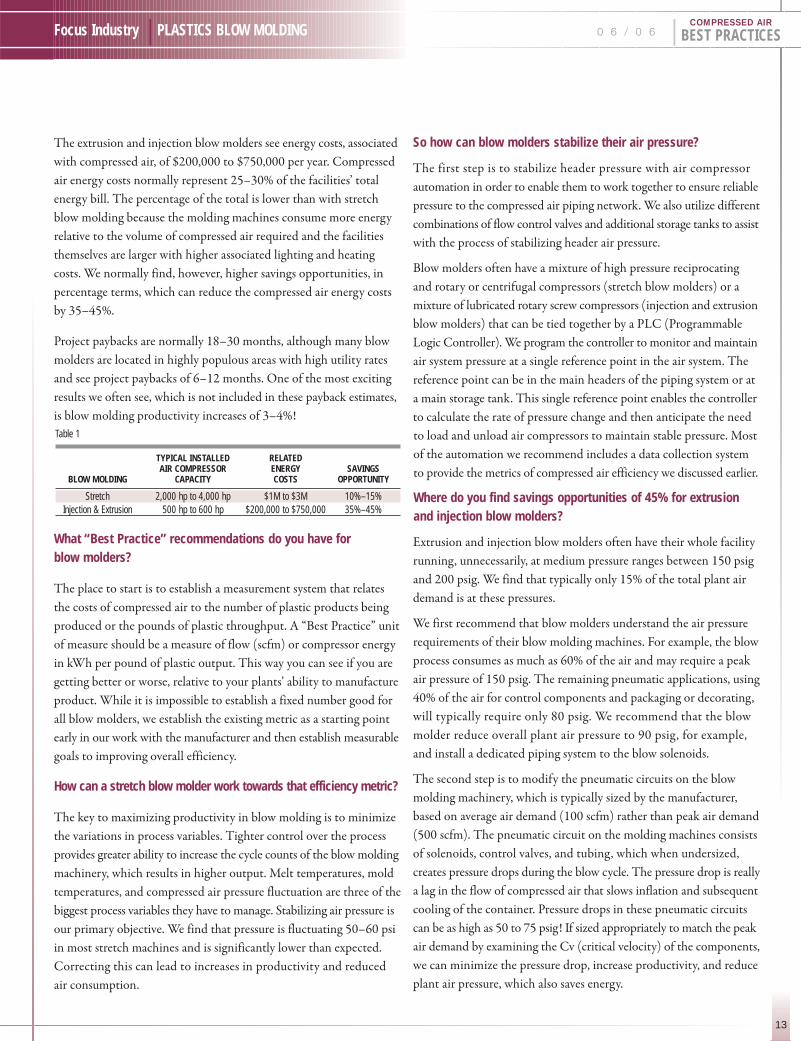
Table 1
TYPICAL INSTALLED RELATED AIR COMPRESSOR ENERGY SAVINGS
BLOW MOLDING CAPACITY COSTS OPPORTUNITY
Stretch 2,000 hp to 4,000 hp $1M to $3M 10%–15%Injection & Extrusion 500 hp to 600 hp $200,000 to $750,000 35%–45%
E X T R U S I O N B L O W M O L D I N G B E S T P R A C T I C E SInterview with Dean Smith
14
BEST PRACTICES | 0 6 / 0 6 Focus Industry | PLASTICS BLOW MOLDINGCOMPRESSED AIR
We recently went through this process at one of the nations’ largest blow molding facilities
and dropped their blowing air pressures from 150 psig to 90 psig. The blow molding
machines were actually able to increase output, at the lower pressure, because the pressure
inside the mold was stabilized!
What “Best Practices” can you recommend for air treatment?
Effective air treatment is critical to protect the quality of the products blow molders manufacture.
We recommend cycling refrigerated air dryers, which provide 39˚ F pressure dew points, to dry
the air. We often find that each air compressor has a dedicated dryer, with a pressure drop of
8–10 psig, which increases the difficulty of managing multiple compressors. Multiple dryers
also mean multiple drainage locations and more contamination issues. We prefer putting all
the air through one larger dryer with less than 4 psi pressure drop and built-in, redundant,
refrigeration units.
Filtration of particulates and oil aerosols is also critical to protect the products. Here, we often
find fine filtration in the compressor room but find very coarse filters (often part of a Filter-
Regulator-Lubricator) out next to the blow molding machine. This is actually the reverse
of what it should be because of the potential of contamination from the air piping itself.
We recommend coarser filters, like mist eliminators with low pressure drops, in the compressor
room and 0.001 coalescers and activated carbon filters at the point of use. Please note that
we oversize the point-of-use filters to minimize the pressure drops
Demand drains are also important to effectively remove the condensate from the dryers and
filters. The “no air-loss” type is suggested to prevent any unnecessary and wasteful blow-off
of air. We particularly like the new electronic demand drains with built-in alarms to indicate
a failure to pass condensate, which can prevent a contaminated system. The drained off condensate
should have the oil separated from the water, so that the oil can be disposed of responsibly.
Depending upon the types of lubricants present in the air system, we recommend gravitational
and/or emulsion type oil-water separators.
What “Best Practices” can you recommend for air piping systems?
SMITH: A good practice is to immediately increase, by one nominal pipe size, the piping
connected to the outlet of the air compressor. We often see piping matching up with the size
of the air compressor outlet pipe. This is logical, but the air compressor manufacturer sized
its piping for the short routing and confined space of the air compressor and not for the air
system! Pipe that is too small causes restrictions to air flow and back pressure on the compressor.
We also specify full port ball and butterfly valves at the compressor outlet. Often we see gate
and plug valves that have reduced ports creating restrictions and pressure loss. These valves
are heavy and expensive and, over long periods of time, tend to not seal well when closed.
Thank you DEAN SMITH for your “BEST PRACTICES” recommendations.
Dean Smith has 15 years experience as a consultant in compressed air and gas systems having conductedcomplete audits on over 1000 plant air systems in a variety of industries. Contact at (678) 355-1192 and [email protected].
“Pressure drops .
in these
pneumatic
circuits can be
as high as
50 to 75 psig!”

Now that AirCel® has joined Ultrafilter®
in becoming part of Donaldson, weoffer you broad and complete solutions forcompressed air treatment!
www.donaldson.com/en/compressor/index.html • [email protected] • Minneapolis MN USA
��
��
�
Dryers: refrigerated, desiccant, membrane type —in various configurations
Advanced condensate management—zero air-lossdrain valves & oil/water separators
Water chillers
Filters are in-stock for fast delivery!
Made in the USA—shorter lead times!
Filters, Dryers, ChillersFilters, Dryers, ChillersCompressed AirCompressed Air

F O U R S A V I N G S A R E A S I N C O M P R E S S E D A I R S Y S T E M SBY HANK VAN ORMER
16
BEST PRACTICES | 0 6 / 0 6 Focus Industry | PLASTICS BLOW MOLDINGCOMPRESSED AIR
Compressed air is often overlooked in energy studies because many people do not fully
understand compressed air equipment, the air system or what it costs to produce compressed
air power. For those willing to look and use some good old common sense it is a land of
opportunity.
Just how expensive is compressed air? Well, as a transfer of energy to do work “Electric to Air
Power”, it is a really lousy deal. It takes about 8 HP of electrical energy to produce 1 HP worth
of work with compressed air. Do you think your electric power is expensive? Your air power
is 8 times more!
What Is Going On?
Every process in your plant, which has a need for compressed air, has a minimum supply in CFM
(flow) and PSIG (pressure required), for the process to run at optimum levels. When you supply
air at a higher pressure and consequently more volume, you create extra expense, but with
no increase in productivity or quality. This situation is often called “Artificial Demand”.
Do you know the lowest effective pressure / flow requirement at each process? Do you measure
and monitor to stay on target? Do you use/supply too much air? The compressed air system
will continue to use more air volume as the pressure rises. For that matter, do you know your
cost of compressed air? How much air do you use? It is probable that some one knows the cost
of your electric power and useage every month. You cannot manage the use and cost of compressed
air if you do not measure and monitor.
Some Tidbits:
1. The electrical energy cost of producing compressed air is generated by the flow and pressure which creates HORSE POWER, turns into INPUTkW x $/kw RATE x HOURS = $$$$$ electrical cost per year associatedwith compressed air.
2. In order to actually reduce energy cost you must reduce the pressure and flow from the compressor supply. Actions, on the demand side,that do not translate into lower input energy do not provide an economic savings.
3. Typical Energy Cost of Air:
4. At $.06 kWh at 8000 hours per year, with an air supply that produces 4.0 cfm per input horse power:
a. 1 cfm cost = $100 per year in energy cost
b. 2 psig cost = $398 per year in energy cost for every 100 HP
5. 50% of the air produced in industrial plants IS NOT USED FOR PRODUCTION!!!! This is what we call opportunity.
Where are the most common opportunities we observe in air systems during our audits?
“Do you think .
your electric power
is expensive?
Your air power
is 8 times more!”
17
Focus Industry | PLASTICS BLOW MOLDING 0 6 / 0 6 | BEST PRACTICESCOMPRESSED AIR
#1 Savings Area — Management and Operator Awareness of Compressed Air Energy Costs
Air compressors driven by electric motors will use a surprisingly large amount of energy every
year they are in operation. The annual cost of power for operating compressor will equal or
exceed the initial cost of the unit.
The initial purchase price of a 100HP air compressor will range from $30,000 and $50,000
depending on the type and option. The same 100HP compressor operating some hours per
year (a power rate of $0.06/kWh and a motor efficiency of 0.90) will have an annual power
cost of $43,265. Thi is three shifts, 7 days a week, 47–48 weeks per year.
You can estimate the appropriate annual electric power cost of your compressors with this
formula. First, multiply the horsepower of the compressor by 0.746, times the hours of operation,
times your power rate (i.e.: HP X .746 X hours X power rate). Then, divide that number
by the motor efficiency.
Everyone in the plant should know the total power cost for operating the compressors.
This is especially important for anyone working with air-operated equipment.
#2 Savings Area — Reduce Pressure Losses in the Interconnecting Piping and Air Treatment Equipment
The piping and air treatment equipment found between the air compressor discharge and
the process is the most overlooked area in air systems. Even though the calculated “Friction
Pressure Loss” may be low for the pipe, poor piping system designs (convoluted piping, crossing
tee connections and dead heads) may cause significant “turbulence driven” backpressure.
This not only wastes power, but also can cause the unloading controls to become ineffective.
Poorly selected filters and dryers, without regard to pressure loss, merely compound this.
In a well laid out system, the interconnecting piping from the compressed air supply to the
process (and to the header distribution piping) should create NO pressure loss — thus including
the main piping headers as part of the “effective storage”. Some of the more common piping
opportunities we find are:
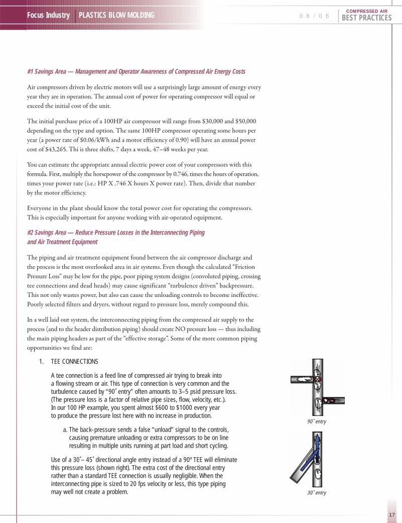
1. TEE CONNECTIONS
A tee connection is a feed line of compressed air trying to break into a flowing stream or air. This type of connection is very common and theturbulence caused by “90˚ entry” often amounts to 3–5 psid pressure loss.(The pressure loss is a factor of relative pipe sizes, flow, velocity, etc.).In our 100 HP example, you spent almost $600 to $1000 every year to produce the pressure lost here with no increase in production.
a. The back-pressure sends a false “unload” signal to the controls,causing premature unloading or extra compressors to be on line resulting in multiple units running at part load and short cycling.
Use of a 30˚– 45˚ directional angle entry instead of a 90º TEE will eliminatethis pressure loss (shown right). The extra cost of the directional entryrather than a standard TEE connection is usually negligible. When theinterconnecting pipe is sized to 20 fps velocity or less, this type pipingmay well not create a problem.
90˚ entry
30˚ entry
F O U R S A V I N G S A R E A S I N C O M P R E S S E D A I R S Y S T E M SBY HANK VAN ORMER
18
BEST PRACTICES | 0 6 / 0 6 Focus Industry | PLASTICS BLOW MOLDINGCOMPRESSED AIR
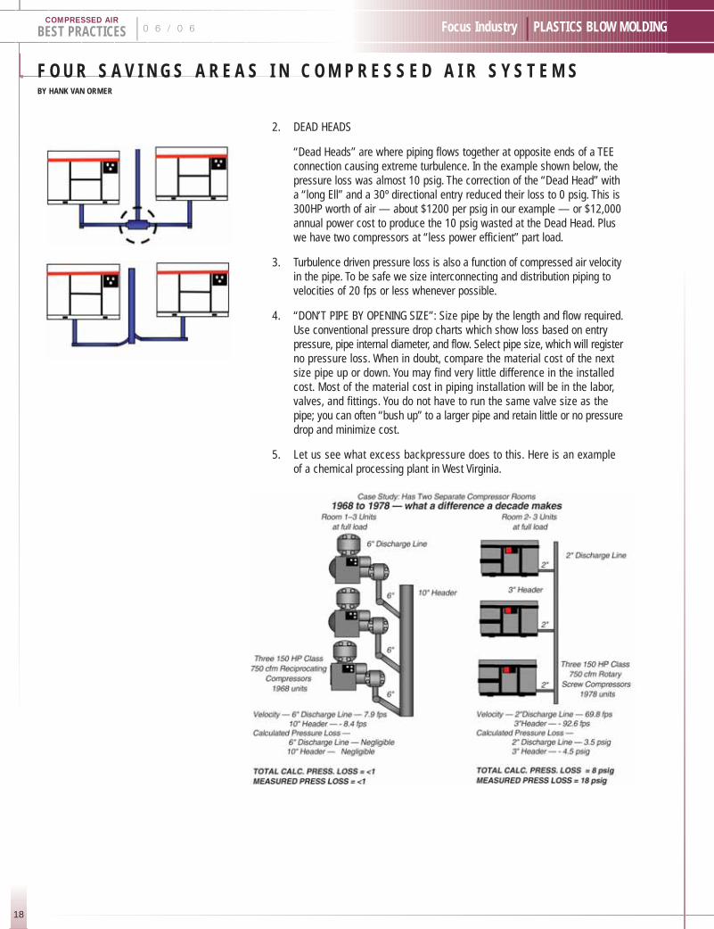
2. DEAD HEADS
“Dead Heads” are where piping flows together at opposite ends of a TEEconnection causing extreme turbulence. In the example shown below, thepressure loss was almost 10 psig. The correction of the “Dead Head” witha “long Ell” and a 30º directional entry reduced their loss to 0 psig. This is300HP worth of air — about $1200 per psig in our example — or $12,000annual power cost to produce the 10 psig wasted at the Dead Head. Pluswe have two compressors at “less power efficient” part load.
3. Turbulence driven pressure loss is also a function of compressed air velocityin the pipe. To be safe we size interconnecting and distribution piping tovelocities of 20 fps or less whenever possible.
4. “DON’T PIPE BY OPENING SIZE”: Size pipe by the length and flow required.Use conventional pressure drop charts which show loss based on entrypressure, pipe internal diameter, and flow. Select pipe size, which will registerno pressure loss. When in doubt, compare the material cost of the nextsize pipe up or down. You may find very little difference in the installedcost. Most of the material cost in piping installation will be in the labor,valves, and fittings. You do not have to run the same valve size as thepipe; you can often “bush up” to a larger pipe and retain little or no pressuredrop and minimize cost.
5. Let us see what excess backpressure does to this. Here is an exampleof a chemical processing plant in West Virginia.

19
Focus Industry | PLASTICS BLOW MOLDING 0 6 / 0 6 | BEST PRACTICESCOMPRESSED AIR
6. In the preceding case study, eight psig of pressureloss was “frictional loss” in the pipe. Ten psig wascaused by turbulence driven backpressure fromthe “crossing tees” at the high velocity. We seethis problem in more than 90% of the multiple unitplants we review. With step controls, this wouldcause short cycling – keeps more than one unit on at part load and can lead to premature failureof such components such as coolers, bearings,motors, etc.
#3 Savings Area — Compressed Air Leaks:
Assuming the interconnecting piping and controls are operating
correctly, and will now respond with a proportional reduction in input
energy to a reduction in air demand, leaks are the next critical target.
It has been our experience that plants, which have no formal, monitored,
disciplined, compressed air leak management program, will have a
cumulative leak level equal to 30% or more of the total air demand.
All plants can benefit from a formal ongoing leak management program.
The most effective programs are those that involve the production
supervisors and operators working in concert with the maintenance
personnel. Accordingly, it is suggested that all programs consist of
the following:
p Short Term — Set up a continuing leak inspectionby Maintenance Personnel so that for a while, eachprimary sector of the plant is inspected once eachquarter or at least, once every six months toidentify and repair leaks. A record should bekept of all findings, corrective measures, andoverall results. Inspections should be conductedwith a high quality ultrasonic leak locator duringproduction and non-production.
p Long Term — Consider setting up programs tomotivate the operators and supervisors to identifyand repair leaks. One method that has workedwell with many operations is to monitor the airflowto each department and make each departmentresponsible for identifying its air usage as ameasurable part of the operating expense for thatarea. This usually works best when combined withan effective in-house training, awareness, andincentive program.
Continued on page 53
SUBSCRIBE NOW!C O M I N G E D I T I O N S !
Energy Efficiency, Printing, Hospitals, Food Processing,Concrete, Manufacturing Productivity
I D E A L F O R :INDUSTRY:
Plant Engineers, Plant Managers & Maintenance Managers
COMPRESSOR DISTRIBUTORS:Every Branch Location
MANUFACTURERS:Management, Sales, Marketing & Engineering
Rates: 12-month SubscriptionNumber of
Subscriptions 1-10 11-19 20-49 50+
U.S. $175.00 $160.00 $140.00 $130.00
Canada $185.00 $170.00 $150.00 $140.00
International $220.00 $205.00 $195.00 $180.00
3 W A Y S T O S U B S C R I B E :*
1.) Visit www.airbestpractices.com and use your Visa/Mastercard
2.) Email us at [email protected] mail your check.
3.) Mail your information and check to:Compressed Air Best Practices161 Clubhouse CircleFairhope, AL 36532
Checks should be made out to “Smith Onandia Communications, LLC ”. Questions call Patricia Smith: 251-510-2598.
*Information Required:
First Name:
Last Name:
Company Name:
Street: City:
State(Province): Zip Code:
Country: email:
Phone: Fax:
The Compressed Air Challenge® (CAC) was founded in 1997 as a not-for-profit, national
collaborative of public and private organizations dedicated to enhancing industrial
competitiveness by improving efficiency of compressed air systems within U.S. Industry.
This mission has recently been extended with the addition of Canadian sponsors. The CAC
accomplishes its mission through the development and offering of training and technical
publications with no commercial bias. Training classes are currently available at three levels:
Fundamentals of Compressed Air Systems, Advanced Management of Compressed Air Systems,
and (in cooperation with the US Department of Energy) Qualified AIRMaster+ Specialist.
The CAC is comprised of industrial end users, utilities, state and national energy organizations,
energy efficiency associations, and representatives of the compressed air equipment industry.
The CAC’s training classes are unique in that they are product-neutral and systems-focused.
Students such as plant engineers, operators, and maintenance staff attend the one-day
Fundamentals class to learn how their facilities can achieve 15–25 percent cost savings
through more efficient production and use of compressed air. Fundamentals students also
receive the state-of-the-art reference manual, Best Practices for Compressed Air Systems1.
Students return to their facilities with increased awareness of compressed air system operating
costs and a variety of practical tools to improve productivity and reduce energy expenses. The
intensive, two-day Advanced Management class provides more in-depth technical information
on troubleshooting and making improvements to industrial compressed air systems. Qualified
AIRMaster+ Specialist training is a 3-1/2 day class, including a rigorous exam, designed for
individuals who have completed the Advanced class, have a significant amount of experience
in compressed air systems, and who wish to qualify for the use of the AIRMaster+ software.
For information about Qualified AIRMaster + training, see http://www1.eere.energy.gov/
industry/bestpractices/airmaster.html.
Advanced Management of
Compressed Air Systems classes
are being planned for several
locations including Denver,
Atlanta, and Vermont.
To view the up-to-date list of training opportunities and to learn about co-hostingCAC training classes, see the CAC’s website at www.compressedairchallenge.org
1No relationship to Compressed Air Best Practices Magazine
FUNDAMENTALS OF COMPRESSED AIR SYSTEMS TRAINING OPPORTUNITIES IN 2006 INCLUDE:
June 1 Benbrook, TX Contact: Neal Mukherjee, 972-906-0900
June 8 Tulare, CA Contact: Gary Pikop, 559-625-7127
June 20 Cincinnati, OH Contact: Lawrence Boyd, 216-323-1898
June 21 Omaha, NE Contact: David Nosal, 402-571-5004
June 28 South Portland, ME Contact: Joy Adamson, 207-287-8350
21
Focus Industry | PLASTICS BLOW MOLDING
T H E T Y P E S O F P L A S T I C S U S E D I N B L O W M O L D I N G
0 6 / 0 6 | BEST PRACTICESCOMPRESSED AIR
U.S. Patent 237168 was issued on February 1, 1881, to Celluloid
Novelty Co. and Celluloid Manufacturing Company, New York.
This was the first patent for the processing of extruded polymer into
a parison for blow molding.
The first applications for blow molding were for cellulose nitrate,
and later, in the 1930s, for cellulose acetate. Continuous advancements
in plastics have created more and more applications for the blow molding
of plastics and have helped this become a major industry in the
United States.
Low-density Polyethylene (LDPE)
Blow molding remained a relatively small part of the plastics
manufacturing scene until the introduction of Low Density Polyethylene
(LDPE) in the 1940s. The production of LDPE squeeze bottles
by Monsanto caused a rapid expansion of the industry, with containers
produced to replace glass bottles for shampoos and liquid soaps.
Low-density polyethylene (LDPE) is a thermoplastic made from oil.
This was the first grade of polyethylene, produced in 1933 by ICI,
using a high pressure process via free radical polymerisation. It is
translucent or opaque, quite flexible, and tough to the degree of being
almost unbreakable. It is widely used for manufacturing various
containers, dispensing bottles, wash bottles, tubing, and plastic bags.
High-density Polyethylene (HDPE)
The mass production of High Density Polyethylene (HDPE) and
Polypropylene (PP) in the 1950s led to a further ramp-up in blow
molding demand, for applications such as liquid detergents, motor
oil, water, and milk. The lightweight HDPE gallon milk container
revolutionized the dairy industry, as glass bottles and paperboard
were quickly replaced.
HDPE is a polyethylene thermoplastic made from petroleum.
HDPE has little branching, giving it stronger intermolecular forces
and tensile strength than lower density polyethylene. HDPE is also
somewhat harder and more opaque and it can withstand rather high
temperatures. HDPE is resistant to many different solvents and has
a wide variety of applications, including Tupperware containers,
laundry detergent bottles, milk cartons, and plastic lawn bags.
Polypropylene (PP)
Polypropylene or polypropene (PP) is a thermoplastic polymer used
in a wide variety of applications, including food packaging, textiles,
laboratory equipment, loudspeakers, and automotive components.
An additon polymer made from the monomer propylene, it is unusually
resistant to many chemical solvents, bases, and acids.
Most commercial polypropylene has a level of crystallinity intermediate
between that of LDPE and HDPE. Although it is less tough than
LDPE, it is much less brittle than HDPE. This allows polypropylene
to be used as a replacement for engineering plastics, such as ABS.
Polypropylene has very good resistance to fatigue, so that most plastic
living hinges, such as those on flip-top bottles, are made from this material.
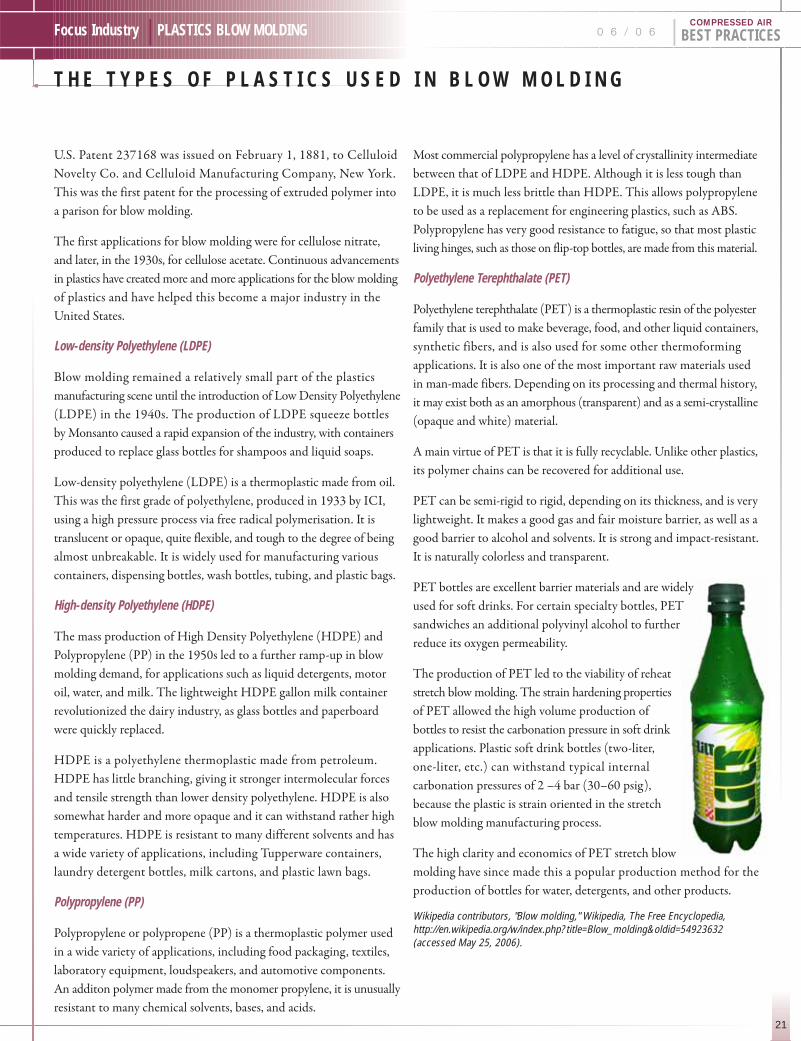
Polyethylene Terephthalate (PET)
Polyethylene terephthalate (PET) is a thermoplastic resin of the polyester
family that is used to make beverage, food, and other liquid containers,
synthetic fibers, and is also used for some other thermoforming
applications. It is also one of the most important raw materials used
in man-made fibers. Depending on its processing and thermal history,
it may exist both as an amorphous (transparent) and as a semi-crystalline
(opaque and white) material.
A main virtue of PET is that it is fully recyclable. Unlike other plastics,
its polymer chains can be recovered for additional use.
PET can be semi-rigid to rigid, depending on its thickness, and is very
lightweight. It makes a good gas and fair moisture barrier, as well as a
good barrier to alcohol and solvents. It is strong and impact-resistant.
It is naturally colorless and transparent.
PET bottles are excellent barrier materials and are widely
used for soft drinks. For certain specialty bottles, PET
sandwiches an additional polyvinyl alcohol to further
reduce its oxygen permeability.
The production of PET led to the viability of reheat
stretch blow molding. The strain hardening properties
of PET allowed the high volume production of
bottles to resist the carbonation pressure in soft drink
applications. Plastic soft drink bottles (two-liter,
one-liter, etc.) can withstand typical internal
carbonation pressures of 2 –4 bar (30–60 psig),
because the plastic is strain oriented in the stretch
blow molding manufacturing process.
The high clarity and economics of PET stretch blow
molding have since made this a popular production method for the
production of bottles for water, detergents, and other products.
Wikipedia contributors, "Blow molding," Wikipedia, The Free Encyclopedia,http://en.wikipedia.org/w/index.php?title=Blow_molding&oldid=54923632(accessed May 25, 2006).
T H E B A S I C S I N B L O W M O L D I N G M A C H I N E S A N D P R O C E S S E SBY COMPRESSED AIR BEST PRACTICES
22
BEST PRACTICES | 0 6 / 0 6 Focus Industry | PLASTICS BLOW MOLDINGCOMPRESSED AIR
Blow molding is a manufacturing method involving the forming of hollow articles out of thermo-plastic materials. The process involves forming a molten tube of thermoplastic material, thenwith the use of compressed air, blowing up the tube to conform to the interior of a chilled blowmold. The most common methods are injection-stretch, extrusion, and injection blow molding.Compressed air plays a vital role in the blow molding process and is used at pressures rangingfrom 60 psig to 580 psig.
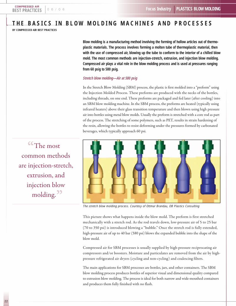
Stretch blow molding—Air at 580 psig
In the Stretch Blow Molding (SBM) process, the plastic is first molded into a “preform” using
the Injection Molded Process. These preforms are produced with the necks of the bottles,
including threads, on one end. These preforms are packaged and fed later (after cooling) into
an SBM blow molding machine. In the SBM process, the preforms are heated (typically using
infrared heaters) above their glass transition temperature and then blown using high pressure
air into bottles using metal blow molds. Usually the preform is stretched with a core rod as part
of the process. The stretching of some polymers, such as PET, results in strain hardening of
the resin, allowing the bottles to resist deforming under the pressures formed by carbonated
beverages, which typically approach 60 psi.
This picture shows what happens inside the blow mold. The preform is first stretched
mechanically with a stretch rod. As the rod travels down, low-pressure air of 5 to 25 bar
(70 to 350 psi) is introduced blowing a “bubble.” Once the stretch rod is fully extended,
high-pressure air of up to 40 bar (580 psi) blows the expanded bubble into the shape of the
blow mold.
Compressed air for SBM processes is usually supplied by high-pressure reciprocating air
compressors and/or boosters. Moisture and particulates are removed from the air by high-
pressure refrigerated air dryers (cycling and non-cycling) and coalescing filters.
The main applications for SBM processes are bottles, jars, and other containers. The SBM
blow molding process produces bottles of superior visual and dimensional quality compared
to extrusion blow molding. The process is ideal for both narrow and wide-mouthed containers
and produces them fully finished with no flash.
The stretch blow molding process. Courtesy of Ottmar Brandau, OB Plastics Consulting
“The most .
common methods
are injection-stretch,
extrusion, and
injection blow
molding.”

23
Focus Industry | PLASTICS BLOW MOLDING 0 6 / 0 6 | BEST PRACTICESCOMPRESSED AIR
Extrusion blow molding — Air at 60 to 150 psig
In Extrusion Blow Molding (EBM), plastic is melted and extruded
into a hollow tube (a parison). The parison is then captured by closing
it into a cooled metal mold. Air is then blown into the parison,
inflating it into the shape of the hollow bottle, container, or part.
After the plastic has cooled sufficiently, the mold is opened and the
part is ejected.
EBM is a low-pressure process, with typical blow air pressures of 25
to 150 psi. This low-pressure process allows the production of economical
low-force clamping stations, while parts can still be produced with
surface finishes ranging from high gloss to textured. The resulting
low stresses in the molded parts also help make the containers resistant
to strain and environmental stress cracking.
Compressed air for EBM processes is usually supplied by rotary screw
air compressors with direct or variable speed drives. Moisture and
particulates are removed from the air by refrigerated air dryers (cycling
and noncycling) and coalescing filters.
EBM processes may be either continuous (constant extrusion of the
parison) or intermittent. Types of EBM blow molding equipment may
be categorized as follows:
I. Continuous Extrusion Blow Molding Machinery — Rotary Wheel Systems
Rotary wheel blow molding systems are used for the high-output
production of a wide variety of plastic extrusion blow molded articles.
Containers may be produced from small, single serve bottles to large
containers up to 20–30 liters in volume—but wheel machines are
often sized for the volume and dimensional demands of a specific
container, and are typically dedicated to a narrow range of bottle
sizes once built. Multiple parison machines with high numbers
of molds are capable of producing over one million bottles per day
in some configurations.
Rotary blow molding “wheels” are targeted to the high output
production of containers. They are used to produce containers from
one to seven layers. Rotary wheels, which may contain from six to
thirty molds, feature continuously extruded parisons. Revolving sets
of blow molds capture the parison or parisons as they pass over the
extrusion head. The revolving sets of molds are located on clamp
“stations.” Wheel machines are favored for their processing ease, due
to having only single (or in some cases, two) parisons, and mechanical
repeatability.
The mold close and open actuation is typically carried out through
a toggle mechanism linkage that is activated during the rotational
process by stationary cams. This mechanical repeatability is considered
an advantage by most processors.
The method of wheel rotation is typically conducted through an electric
motor with a “pinion” gear or small gear next to or in mesh with a
rotating “bull” gear or large gear. All utilities for blowing containers
and for mold cooling are carried through the main shaft or the axle
from which the wheel rotates about. These utilities include compressed
air and water. Sequencing functions necessary to inflate the parison
hold the container prior to discharge and discharge is completed by
mechanical actuation and by pneumatic valves—resulting in a high
degree of repeatability.
The growth of wheel machinery in the United States was spurred
by the conversion of motor oil containers from paperboard cans to
plastic bottles, and the conversion of laundry detergent from powder
to liquid form. Additional high volume applications have included
single serve juices and drinkable yogurt, condiments, and household
cleaning supplies.
II. Continuous Extrusion Blow Molding Machinery — Shuttle Systems
Shuttle machines are
a significant work-
horse in the extrusion
blow molding of
hollow plastic articles,
such as bottles for
food storage. Shuttle
machines are either
single-sided or dual-
sided machines, and
can be manufactured
to produce one- to
six-layer containersRotary Wheel Blow Molding Machine Operation. Image provided Courtesy GrahamMachinery Group, York, PA.
Shuttle machinery is used widely in the production ofpersonal care bottles, medical bottles, and somesmall industrial containers — Photo courtesy GrahamMachinery Group, York, PA

T H E B A S I C S I N B L O W M O L D I N G M A C H I N E S A N D P R O C E S S E SBY COMPRESSED AIR BEST PRACTICES
24
BEST PRACTICES | 0 6 / 0 6 Focus Industry | PLASTICS BLOW MOLDINGCOMPRESSED AIR
—although the number of suppliers who produce 4–6 layer machines
is limited. In a single-sided machine, the mold “shuttles” under the
flow-head, closes to capture the parisons, and then moves away from
the head. Blow pins are then forced downward into the molds, helping
to “calibrate” the necks while air is forced into the cavity to blow the
container. The shuttle motion allows the bottles to be blown and
cooled to the side, without interfering with the parisons, which are
continually extruding from the flowhead. In a double-sided shuttle
machine, there is a mold on each side of the flowhead, one shuttling
to the right, and one to the left, which generally doubles the output
of a single-sided machine.
Shuttle machines may extrude single or multiple parisons, and are
characterized by the number of parisons and the horizontal spacing
between the parisons. For example, a 4x100 shuttle extrudes four
parisons, spaced 100 mm between the centers. In general, shuttle
machines up to 2x100 mm spacing are considered small machines;
shuttles up to 6x100 mm spacing are considered mid-sized machines;
shuttles larger than this are typically referred to as “long-stroke”
machines.
Shuttle machinery is used widely in the production of personal care
bottles, medical bottles, and some small industrial containers.
Sequence of Operation
The steps required for a shuttle machine to blow mold a hollow plastic
object can be described by the following sequence of operations:
p As the dropping parisons approach the length ofthe object to be blown, the mold, in open position,shuttles sideways to a point directly under thehead of the machine.
p The molds close to capture the parison.
p A knife cuts the parisons directly above the molds.This may be either a cold knife (cutting with a sharpedge) or a hot knife (burning through the parison).
p The molds shuttle away from the head until theyare directly under the blow pin stations. If the moldmovement is horizontal, the extruder head is madeto bob up vertically, so that the continuously extrudingparisons do not drag against the mold as it movessideways. In some shuttle machinery, the moldsshuttle down at an angle, eliminating the needfor the head and extruders to bob upwards.
p The blow pins are forced down into the still-opennecks of the containers, calibrating the necks ofthe containers. In most cases, the blow pinspunch down onto striker plates, which form thetop edge of the neck to a precise flat dimension.
p Compressed air pressure is applied to blow thecontainers. In many cases, the blow air is turnedon before the blow pins enter the open neck of theparison, forcing the plastic outward and ensuringa good neck formation.
p After the containers have cooled, the molds open,and again shuttle under the head of the machine.As the molds close on the molten parisons, maskingstations that are attached to the sides of the moldclose over the outside of the previously blowncontainers, which are still held in place by theblow pins.
p The blow pins retract, leaving the containers heldonly by the masks.
p As the molds again shuttle sideways, the maskstransfer the formed containers sideways to a punching station. Punches come forward to remove the tails, top moil, and any handle (grip) slugs away from the bottles.
p The bottles are then conveyed out of the machine.This may be done by transferring the bottles ontoconveyor belts, by takeout devices, or by simplydropping the bottles into a chute or onto a take-away conveyor.
III. Intermittent Extrusion Blow Molding Machinery — Reciprocating Screw
Reciprocating screw machinery is used for the extrusion blow molding
of hollow containers. Examples of parts manufactured from these
machines include lightweight HDPE bottles for dairy and water,
as well as large 3–5 gallon polycarbonate bottles for water coolers.
Reciprocating screw blow molding machines are characterized by the
use of a reciprocating screw extruder as is used in injection molding.
As the screw melts the resin, the screw moves backward, allowing
the melted plastic to accumulate in the end of the barrel. When the
screw pushes forward under hydraulic pressure, the plastic is pushed
out of the barrel and extruded through a flowhead and die to form
a plastic parison.
Continued on page 56

25
Compressed Air Industry | PLASTICS BLOW MOLDING 0 6 / 0 6 | BEST PRACTICESCOMPRESSED AIR
K A E S E R C O M P R E S S O R S , I N C .Company Profile
It’s been almost 25 years since Kaeser Compressors, Inc. was established in the United States.
And it was, to say the least, a modest beginning with only three employees. Today it is the largest
subsidiary of Germany’s Kaeser Kompressoren and ranks among the top compressor providers
in the country.
President Reiner Mueller remembers those first few years well. “We took a very practical
approach: steady, controlled growth. We established a top notch distribution network and
gave them an outstanding product to sell,” reflected the elder of the two Muellers who form
the leadership team at Kaeser. “But clearly, it was the hardwork and dedication of our employees
that brought us to where we are today.”
In fact, many of the company’s first employees are still with Kaeser today, including Roy Stuhlman,
Vice President of Sales. A trip through the 100,000 square foot facility reveals dozens of
employees who are celebrating 10, 15, and even 20 years of service. In many ways, longevity
is Kaeser’s strength and a key contributor to its remarkable growth over the years.
As the long days of summer set in, General Manager Frank Mueller is settling into his fifth year
at the helm.Excited by Kaeser's continuing succes, he sat down for an interview and shared
his thoughts on the key points of Kaeser's history and continuing focus: a systems approach
to advanced technology, education, training, and service. “We have a reputation built on quality
and reliability, and it only makes sense that people see us as the compressed air solutions provider.
It’s not one size fits all; not every customer needs the same technology,” he points out.
Advanced Technology
Kaeser’s first technology breakthrough came
in the mid 70s with the development of the
Sigma Profile. This proprietary design provided
over 20% more air per horsepower than
existing rotary screw airends. The Sigma
Profile is standard on all Kaeser rotary screw
compressors in the 3–600 HP range —
the widest range on the market. Direct drive
units feature airends optimized in size and
profile to match lower rotational speeds and
provide the very best specific performance.
In the past decade, Kaeser introduced Sigma
Control — the first industrial-based PC control
system — and combined it with the latest in
variable speed drive technology to create the
Sigma Frequency Control rotary screw
compressors. “We pride ourselves on having
the most efficient range of frequency control
units, along with the expertise to properly
apply the technology for maximum energy
savings,” explains Frank Mueller. Built in 1994, Kaeser's 100,000 sq. foot facility in Fredericksburg, VA was dedicated to it’s employees —the most valuable resource of Kaeser compressors.
General Manager Frank Mueller and PresidentReiner Mueller
“It was the .
hard work and
dedication of our
employees that
brought us to where
we are today.”

K A E S E R C O M P R E S S O R S , I N C .Company Profile
26
BEST PRACTICES | 0 6 / 0 6 Compressed Air Industry | PLASTICS BLOW MOLDINGCOMPRESSED AIR
Taking the next logical step in addressing complete system control, Kaeser recently introduced
the Sigma Air Manager (SAM). This comprehensive air system manager is the first of its kind
to provide remote monitoring and management functionality for all components in the air
system regardless of manufacturer. It can be applied to new or existing systems and enables
reporting through a standard web browser. “When the air system is approached from this
standpoint — meeting specific demands from a systems perspective — it’s not unusual for
customers to save tens of thousands of dollars in energy costs in the first couple of years,”
recounts Mueller.
This practical approach to garnering significant
energy savings for businesses in multiple
industries has led to a successful partnership
with the U.S. Department of Energy’s Office
of Energy Efficiency and Renewable Energy
Industrial Technologies Program. Beginning
in 2001, Kaeser dispatched Wayne Perry,
Technical Director, to the Compressed Air
Challenge’s Best Practices Steering Committee.
Mr. Perry has since traveled extensively to not
only promote a better understanding of
compressed air energy management but also
provide practical solutions for manufacturers in
areas of the world such as China and Indonesia.
Kaeser is also a member of the Compressed Air
and Gas Institute (CAGI), an organization
that promotes awareness of the benefits and
appropriate applications for compressed air as
well as its efficient use. Participating along with
other OEMs and manufacturers in the organization has helped develop a uniform reporting
standard that has revolutionized the industry and brought out a sense of competitiveness.
“And that’s been good for end users as we all strive to meet their demands and provide the
most efficient equipment,” commented Mueller.
Training and Education
Education and training have always been a vital part of the Kaeser equation. “We start by
ensuring that our employees receive very specific training in our products — and branch out
from there,” indicated Mueller. Offering an extensive array of product-specific training for
employees and distributors right from the beginning lead to the development of an entire
technical training department and the establishment of Kaeser’s Factory Certified Training
(KFaCT) program.
Kaeser also offers end-user training through their compressed air seminars. These customized
sessions provide important information on air system design, installation, and operation for
a wide variety of industrial and commercial businesses and are tailored to the audience’s specific
needs and interests. Kaeser owners also have the option of selecting equipment-specific service
training conducted at Kaeser’s state-of-the-art training center.
Kaeser offers a complete line of stationary and portable compressors, blower packages, clean air treatmentequipment, and vacuum systems as well as comprehensive controls and accessories.
27
Compressed Air Industry | PLASTICS BLOW MOLDING 0 6 / 0 6 | BEST PRACTICESCOMPRESSED AIR
Service
As with most companies these days, service is truly a differentiating
factor. “We still answer the phone with a live person — that one to
one interaction is something our customers appreciate. And it’s why
we continue to empower our local representatives with all the tools
they need to provide local, face to face service.”
Capitalizing on the remote monitoring features of Sigma Air Manager
(SAM), some customers enable the local compressor service provider
to log in to their air system. From there, the distributor can monitor
performance, adjust controls, and schedule routine maintenance —
almost eliminating unscheduled downtime. “Service contracts and
remote monitoring arrangements take the burden off the customer
and enable us to further increase a system’s reliability.” For those who
simply want to flip a switch and get the air they need, Kaeser offers
the Sigma Air Utility — a very simple arrangement where Kaeser
installs the equipment on site but still owns the equipment and bills
the customer by the cubic foot of air used.
“Providing the solution that’s right for the customer, not the one that’s
most expensive or impressive — that’s our philosophy,“ Mueller says,
summing it all up. With an expanding network of representatives
nationwide, dedicated employees, and a brisk economy at its back,
Kaeser is focused and determined to continue its positive growth
pattern. When advancing technology and service combine, the success
of Kaeser is inevitable.
Vital Statistics:
Employees Worldwide: over 3,000
Privately held
Product Lines: Rotary screw compressors, clean air treatment equipment
including refrigerated and desiccant dryers, rotary lobe blowers,
vacuum systems, reciprocating compressors, portable compressors,
and control systems.
U.S. Corporate Headquarters:
511 Sigma Drive
Fredericksburg, VA 22408
540-898-5500 Phone
540-898-5520 Fax
www.kaeser.com
For more information contact: Angela Kelly, Public Relations, Kaeser Compressor.Phone 800-777-7873 or visit www.kaeser.com.
SUBSCRIBE NOW!C O M I N G E D I T I O N S !
Energy Efficiency, Printing, Hospitals, Food Processing,Concrete, Manufacturing Productivity
I D E A L F O R :INDUSTRY:
Plant Engineers, Plant Managers & Maintenance Managers
COMPRESSOR DISTRIBUTORS:Every Branch Location
MANUFACTURERS:Management, Sales, Marketing & Engineering
Rates: 12-month SubscriptionNumber of
Subscriptions 1-10 11-19 20-49 50+
U.S. $175.00 $160.00 $140.00 $130.00
Canada $185.00 $170.00 $150.00 $140.00
International $220.00 $205.00 $195.00 $180.00
3 W A Y S T O S U B S C R I B E :*
1.) Visit www.airbestpractices.com and use your Visa/Mastercard
2.) Email us at [email protected] mail your check.
3.) Mail your information and check to:Compressed Air Best Practices161 Clubhouse CircleFairhope, AL 36532
Checks should be made out to “Smith Onandia Communications, LLC ”. Questions call Patricia Smith: 251-510-2598.
*Information Required:
First Name:
Last Name:
Company Name:
Street: City:
State(Province): Zip Code:
Country: email:
Phone: Fax:
S P X D E H Y D R A T I O N & P R O C E S S F I L T R A T I O NCompany Profile
SPX Dehydration & Process Filtration was formed to better describe the breadth and depth of
products and systems created by this division of global multi-industry leader SPX Corporation.
“The products and systems we produce remove moisture and contaminants from air, gas, fuel,
lubricating oil, and insulating fluids to improve operations, processes, and energy efficiency,”
says Bill Kennedy, Director Of Marketing.
Symbolizing innovation, quality and reliability,
world-renowned brands include Delair®,
Deltech®, Dollinger®, Hankison®, Kemp®,
Pneumatic Products®, RentalDryers.com™,
and Vokes. Each offers more than 30 years
of knowledge, expertise, and innovation to
the industrial marketplace. In leveraging the
strengths of a Fortune 500 multinational
company, customers can expect premium
products, leading technology, outstanding
quality, and exceptional customer service.
“Our goal is to deliver a premium buying
experience to our customers,” states Tony
Renzi, President, SPX Dehydration &
Process Filtration.
SPX manufactures products that play an
integral part in the daily productivity of the
world’s leading manufacturers. Applications
are found in everyday life. From the tires on
your car, to the hospital down the street, to
the countless producers of goods and services,
purified air, gases, and fluids improve the
performance and efficiency of everyday
products and complex processes.
Products
SPX products set the standard for industry. Known for dependability, each product delivers
technology to produce choice solutions for a wide range of applications that require clean,
dry air and gas or process fluid cleanliness. The end-user realizes return-on-investment through
process improvements, energy efficiency, and reduced maintenance.
Technological leadership leverages refrigeration, adsorption, permeation, and the principles
of impaction, interception and coalescence, to protect products and processes from contaminants
such as water, oil, dirt, dust, and pollen.
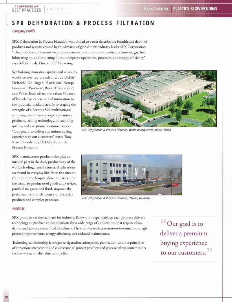
SPX Dehydration & Process Filtration, World Headquarters, Ocala Florida
SPX Dehydration & Process Filtration, Moers, Germany
28
BEST PRACTICES | 0 6 / 0 6 Focus Industry | PLASTICS BLOW MOLDINGCOMPRESSED AIR
“Our goal is to .
deliver a premium
buying experience
to our customers.”

Dehydration products include compressed
air and gas dryers; air and process filtration
products; breathing air packages, condensate
drains, after-coolers, oil-water separators, rental
dryers, accessories, and replacement parts.
Process filtration products include high
efficiency air filtration, gas adsorption and
filtration, process gas filters, coalesers, fuel
and lubricating oil filtration, oil mist
elimination, insulating fluid treatment,
oil exhaust filtration, and pipeline filters.
Resources
Partnered with a global network of authorized
distributors or representatives, local support
is just a phone call away. Factory-trained,
these sales and service professionals under-
stand how to apply the best solutions to
improve plant operations and maximize
productivity. Backed by SPX Dehydration
& Process Filtration’s 17 locations in 11
countries, global engineering and application
teams have the expertise and network to
ensure market-tailored results with off-the-
shelf products or custom engineered systems.
Industries served include: power generation,
chemical, petrochemical, transportation,
automotive, aerospace, machinery equipment
manufacturers, semiconductor, pulp and paper,
primary metal, glass, food and beverage,
telecommunications, health, and medical.
For more information contact: Bill Kennedy, Director of Marketing, SPX Dehydration & Process Filtration.Phone (352) 873-5126 or visit www.spxdehydration.com
29
Focus Industry | PLASTICS BLOW MOLDING 0 6 / 0 6 | BEST PRACTICESCOMPRESSED AIR
V a r i a b l e S p e e d A i r C o m p r e s s o r sJ U L Y 2 0 0 6
C O M I N G N E X T M O N T H !
W W W. A I R B E S T P R A C T I C E S . C O M
Q & A — T E N C A R V A : S T R O N G C U S T O M E R R E L A T I O N S H I P SInterview with Rod Lee, (President) and Bill Strong (Vice President) of the Tencarva Machinery Company
30
BEST PRACTICES | 0 6 / 0 6 Compressed Air Industry | PLASTICS BLOW MOLDINGCOMPRESSED AIR
COMPRESSED AIR BEST PRACTICES: When and how was Tencarva started?
TENCARVA: The Tencarva Machinery Company was formed in 1978 by a group of 18 sales
engineers, including Bill and myself, and one accountant with experience in air compressors
and pumps. We formed an S Corporation, which is employee-owned, and retain that same
structure today. Tencarva today has 62 owners all of whom hold sales or management positions
in the company.
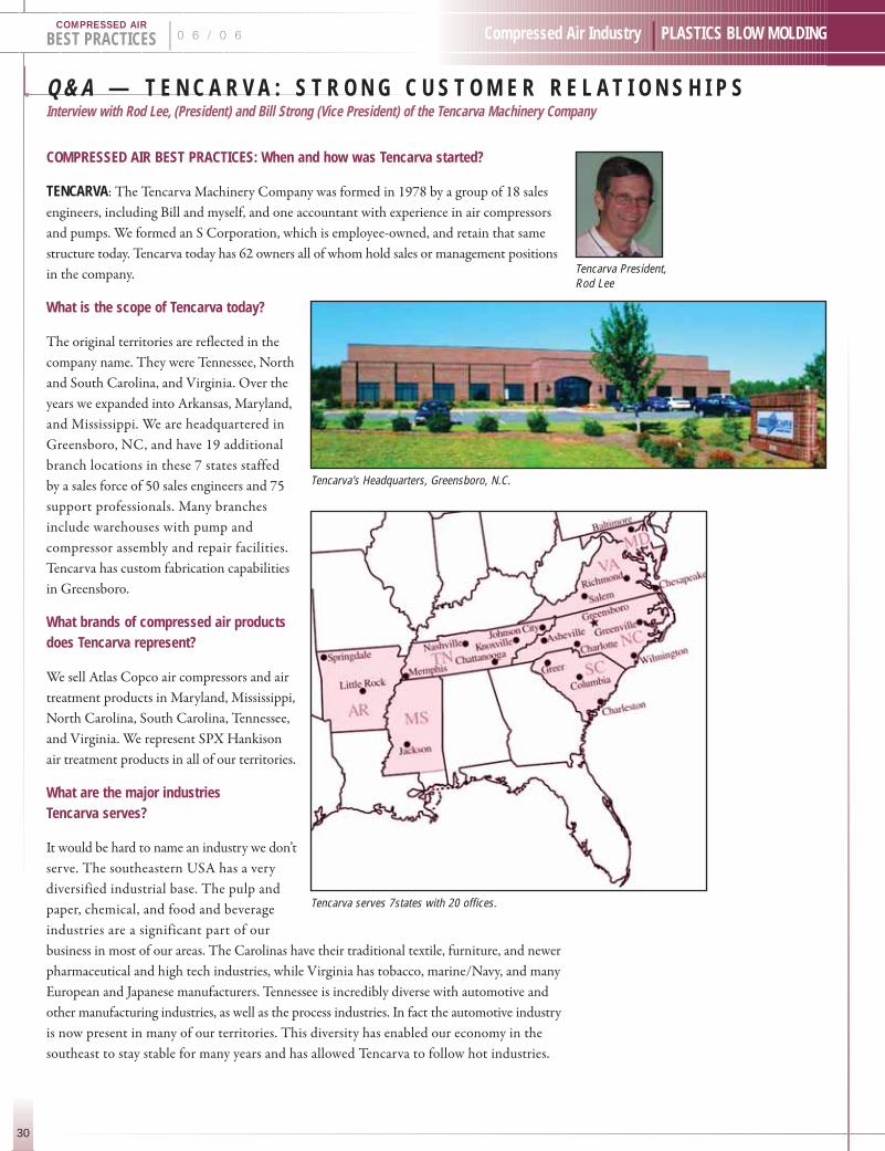
What is the scope of Tencarva today?
The original territories are reflected in the
company name. They were Tennessee, North
and South Carolina, and Virginia. Over the
years we expanded into Arkansas, Maryland,
and Mississippi. We are headquartered in
Greensboro, NC, and have 19 additional
branch locations in these 7 states staffed
by a sales force of 50 sales engineers and 75
support professionals. Many branches
include warehouses with pump and
compressor assembly and repair facilities.
Tencarva has custom fabrication capabilities
in Greensboro.
What brands of compressed air products does Tencarva represent?
We sell Atlas Copco air compressors and air
treatment products in Maryland, Mississippi,
North Carolina, South Carolina, Tennessee,
and Virginia. We represent SPX Hankison
air treatment products in all of our territories.
What are the major industries Tencarva serves?
It would be hard to name an industry we don’t
serve. The southeastern USA has a very
diversified industrial base. The pulp and
paper, chemical, and food and beverage
industries are a significant part of our
business in most of our areas. The Carolinas have their traditional textile, furniture, and newer
pharmaceutical and high tech industries, while Virginia has tobacco, marine/Navy, and many
European and Japanese manufacturers. Tennessee is incredibly diverse with automotive and
other manufacturing industries, as well as the process industries. In fact the automotive industry
is now present in many of our territories. This diversity has enabled our economy in the
southeast to stay stable for many years and has allowed Tencarva to follow hot industries.
Tencarva serves 7states with 20 offices.
Tencarva President,Rod Lee
Tencarva’s Headquarters, Greensboro, N.C.

31
Compressed Air Industry | PLASTICS BLOW MOLDING 0 6 / 0 6 | BEST PRACTICESCOMPRESSED AIR
How does Tencarva take compressed air products to market?
The focus is not on products but on customer relationships. The broad range of products
offered by Tencarva affords the opportunity to have broader relationships with customers.
We can talk about pumps and compressed air with our customers. This allows our sales
engineers to get to know our customers, their processes and needs extremely well, and thereby
add more value to their operation. Tencarva has 50 sales engineers calling on our customers.
In any given area, we have two to three times more people than the competition, which only
work with compressed air. Because we offer both pumps and compressed air products, we are
able to create small sales territories, which in turn allows our sales engineers to build strong
and valuable customer relationships.
There are industrial supply houses with smaller territories, but they do not have the technical
expertise in compressed air products that Tencarva sales engineers have. There is an optimum
point between technical product knowledge and closeness to the customer which we believe
we have found.
Tencarva also sells pumps. How does Tencarva handle both pumps and compressed air products?
We feel this is a strength for Tencarva. We put a technically skilled person, with a small
territory, frequently into the same plant. This sales engineer, who can handle both product
lines technically, gives us the ability to spend more time in a specific facility and better
understand their processes and their needs. The somewhat longer interval between
compressor needs and sales is addressed by this strategy. Our work with pumps and other
process equipment supports our presence until the next compressor project comes along.
The challenge this poses is to train our sales engineers appropriately in both compressed
air and pumping systems. It isn’t easy to do. We have to stay abreast of the changes and
technological advances. For this reason, we hire people who can learn quickly and who
have the technical background on how a machine works. In this manner, they can learn
a broad spectrum of products.
How does Tencarva recruit, train, and retain its sales engineers?
People are at the core of Tencarva’s strategy, and this is where we focus our investments. We take
a long-term approach to creating a Tencarva sales engineer and/or service technician. The benefits
are that those who go through our development process tend to spend their whole careers with
Tencarva. We pay very well, and most of our sales engineers are part owners of the company.
Turnover is next to nothing once they have been a Tencarva sales engineer for two to three years.
We begin the process by investing in recruiting at engineering schools for people with technical
educations. We hire people right out of college, which is a difficult process and requires a large
investment. North Carolina State, Clemson, and East Carolina have been the mainstays. Recently,
we recruited at Tennessee Tech, Mississippi State, and the University of Arkansas. We look for
people with sound technical foundations who are fast learners and have a strong work ethic.
Tencarva personnel using Atlas Copco’s M-Box canmeasure and analyze customers’ actual compressedusage and needs for sizing compressors for optimumefficiency and energy savings.
Tencarva service specialists utilize laptop computersto keep track of the latest factory service updates onall Atlas Copco compressors.
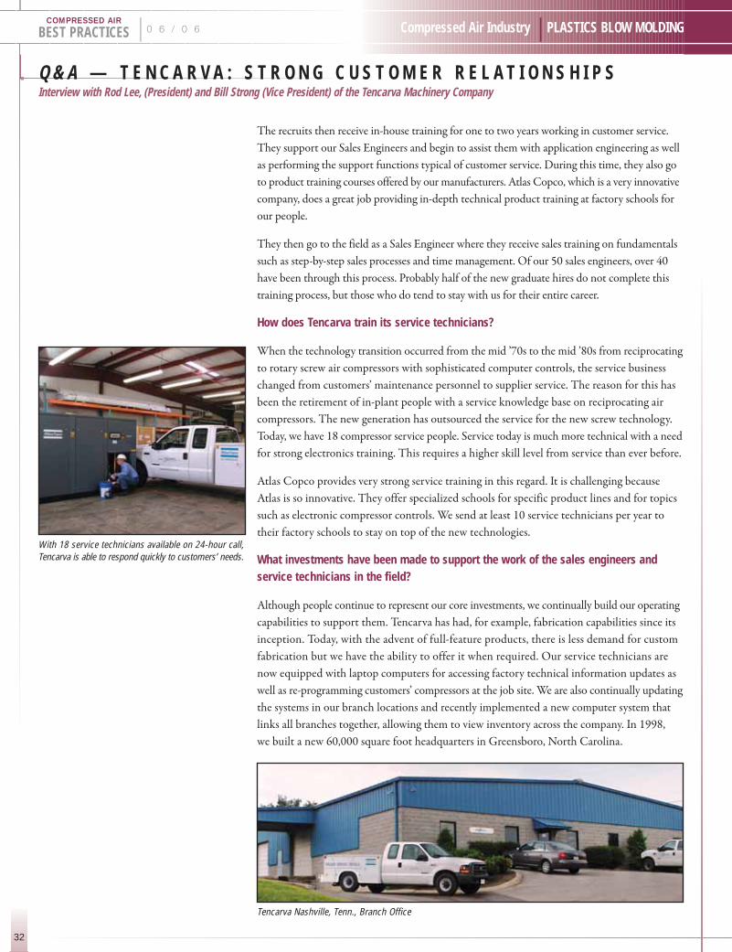
Q & A — T E N C A R V A : S T R O N G C U S T O M E R R E L A T I O N S H I P SInterview with Rod Lee, (President) and Bill Strong (Vice President) of the Tencarva Machinery Company
32
BEST PRACTICES | 0 6 / 0 6 Compressed Air Industry | PLASTICS BLOW MOLDINGCOMPRESSED AIR
The recruits then receive in-house training for one to two years working in customer service.
They support our Sales Engineers and begin to assist them with application engineering as well
as performing the support functions typical of customer service. During this time, they also go
to product training courses offered by our manufacturers. Atlas Copco, which is a very innovative
company, does a great job providing in-depth technical product training at factory schools for
our people.
They then go to the field as a Sales Engineer where they receive sales training on fundamentals
such as step-by-step sales processes and time management. Of our 50 sales engineers, over 40
have been through this process. Probably half of the new graduate hires do not complete this
training process, but those who do tend to stay with us for their entire career.
How does Tencarva train its service technicians?
When the technology transition occurred from the mid ’70s to the mid ’80s from reciprocating
to rotary screw air compressors with sophisticated computer controls, the service business
changed from customers’ maintenance personnel to supplier service. The reason for this has
been the retirement of in-plant people with a service knowledge base on reciprocating air
compressors. The new generation has outsourced the service for the new screw technology.
Today, we have 18 compressor service people. Service today is much more technical with a need
for strong electronics training. This requires a higher skill level from service than ever before.
Atlas Copco provides very strong service training in this regard. It is challenging because
Atlas is so innovative. They offer specialized schools for specific product lines and for topics
such as electronic compressor controls. We send at least 10 service technicians per year to
their factory schools to stay on top of the new technologies.
What investments have been made to support the work of the sales engineers andservice technicians in the field?
Although people continue to represent our core investments, we continually build our operating
capabilities to support them. Tencarva has had, for example, fabrication capabilities since its
inception. Today, with the advent of full-feature products, there is less demand for custom
fabrication but we have the ability to offer it when required. Our service technicians are
now equipped with laptop computers for accessing factory technical information updates as
well as re-programming customers’ compressors at the job site. We are also continually updating
the systems in our branch locations and recently implemented a new computer system that
links all branches together, allowing them to view inventory across the company. In 1998,
we built a new 60,000 square foot headquarters in Greensboro, North Carolina.
With 18 service technicians available on 24-hour call,Tencarva is able to respond quickly to customers’ needs.
Tencarva Nashville, Tenn., Branch Office

33
Compressed Air Industry | PLASTICS BLOW MOLDING 0 6 / 0 6 | BEST PRACTICESCOMPRESSED AIR
Tencarva Chesapeake, Va., Branch Office Tencarva Memphis, Tenn., Branch Office
“Tencarva has .
50 sales engineers
calling on our
customers. In any
given area, we have
2-3 times more
people than the
competition”
We stock parts and the small rotary screw GX Series air compressors from Atlas Copco to
ensure fast deliveries. Atlas Copco provides finished goods inventory at its warehouse in
Rock Hill, South Carolina, for all other models, and this functions well for our customers.
What do you recommend to end users with regards to their compressed air systems?
Customers need to always remind themselves to take a broader view of their system. Most
problems are created by “add-ons” meant to take care of a specific need. After you do this six
times, you can have an inefficient system. They should consult with system specialists who
can provide advice on the entire system. The work of the Compressed Air Challenge has been
a real benefit to the industry on this topic.
Today the focus is on compressor controls. Variable speed drives are everywhere with air
compressors and pumps. They provide opportunities for greater efficiencies. Controlling and
sequencing is also gaining attention.
The simple things, however, are still there. Fix leaks and don’t let drain traps blow off too
much air!
How can compressed air machinery manufacturers and distributors work together to better meet the needs of the industry?
The manufacturers need to be continually improving their equipment—even though this places
a training burden on distribution. New materials and new drive capabilities can provide benefits
to the customer.
While doing this, they need to listen to the Voice of the Customer to ensure the customer’s system
operates better. Distributors need to better provide this feedback to the manufacturer and then
get customers to adopt the innovations. If everyone does this well, systems will run better.
Many customers don’t know what they need. It wasn’t long ago that few people used air dryers.
People had water in their air systems but didn’t think they had a problem! Distributors must
help customers understand the technical issues and provide counsel to educate the customer.
Thank you TENCARVA for your insights.
For more information contact: Rod Lee, President, Tencarva Machinery Company. Phone (252) 695-0400or visit www.tencarva.com.

B R A N D I N G C O R P O R A T I O N SBY ROD SMITH
34
BEST PRACTICES | 0 6 / 0 6 Compressed Air Industry | PLASTICS BLOW MOLDINGCOMPRESSED AIR
“Branding” for all corporations can be a challenge. Creating brand awareness, of the right
nature and to the right people, is no simple matter. While branding has long been a key part
of the marketing strategy of consumer goods companies like Nike and Procter & Gamble, it
has now become a critical success factor in industrial corporations.
Corporate Branding
The consolidation of manufacturing companies, under large corporations, has created many
branding challenges. When a corporation acquires a company or owns many divisions, what
should the branding strategy be? Should the brand(s) retain their identities, be dual-branded
with the parent, or simply be absorbed? While there is no one single solution, the answers lie
with the corporation first identifying who their target market is, understanding brand equity
levels, and budgeting the resources required for the chosen corporate branding strategy.
1. Target: Institutional Investors Only: creatingbrand awareness is critical for the parent corporationto promote the value of the company stock prices.This strategy is often chosen when the brands ofthe divisions have far more equity with customersthan with the parent company. The marketingfunding required for this strategy is relatively low.
a. Corporate brand designs, both standalone and with integrated divisional brands, are promoted through corporate marketing via a web site and through printed materials to investors.
b. Divisional branding, on products and promotional materials, does not need to change significantly, which dramatically reduces costs related to the corporate strategy. References to the parent companyare made with web site links and on product literature but are not fully integrated into the divisional brand.
c. A good example of this strategy is executedby United Technologies Corporation, which owns major brands like Carrier, Otis Elevator, and Sullair Corporation.
2. Target: End Users & Institutional Investors:there are many marketing advantages to creatingone giant umbrella brand name in terms of brandawareness. The costs are also significant. When acorporation that holds a major brand name withend users buys a company with reduced brandequity, it can also help that company grow.
a. Divisional brands become product line brand names. Products and literature eitherbear both brand names or just the parent company brand name in new branding designs. Parker Corporation, Ingersoll Rand, and Atlas Copco are good examples.These corporations are able to leverage the parent companies’ brand name to create opportunities for different divisions.
b. While the investment is large for the divisions to rebrand, the exposure for the brand is tremendous to the investment community, as both individual and institutional investors see just one brand name.
c. Warning: the cost-savings of brand-consolidationscan be tempting. Be careful not to underestimatethe power of the divisional brand name. There aremany examples of successful companies that,when acquired and consolidated into the parent,lost the perceived commitment to their brands andended up losing market share. The failure in thisexample usually stems from underestimatingeither the existing brand equity or the resourcesrequired to execute the new branding strategy.
Understanding the target market, the existing brand equity levels, and the available resources for branding will guide a corporation toward the
appropriate branding strategy.
This is the first of a series of articles on industrial branding. Rod Smith is the former Vice President of Sales and Marketing for Hankison, PPC, & Deltech (divisions ofSPX Corporation) as well as for Quincy Compressor (a division of EnPro Industries).
“the answers lie .
with the corporation
first identifying
who their target
market is ”

35
Compressed Air Industry | PLASTICS BLOW MOLDING
I N D U S T R Y N E W SPress Releases
0 6 / 0 6 | BEST PRACTICESCOMPRESSED AIR
P R E C I S I O N Q U A L I T Y C Y L I N D E R S !Efficient, reliable booster compressors to 650 psig
Kaeser Compressors has expanded its proven line of booster compressors. Providing pressures
to 650 psig and flows to 685 cfm fad, these units are a convenient, economical way to boost
existing plant pressure while eliminating the need for expensive, separate high pressure systems.
Mounted on heavy-gauge base plates
with anti-vibration pads, Kaeser
boosters eliminate the need for
special foundations and fastenings.
Standard N Series high pressure
compressors come complete with
TEFC motor and starter, as well as
aluminum cylinder heads and finned
cooper cooling pipes for efficient
aftercooling. Booster Extra Pressure
(EP) compressors include precision
manufactured, two or three cylinder
pumps with 100% duty cycle and a
new forced lubrication system with
continuous, full filtration. These
features, combined with an automatic
v-belt tensioning device, provide
reliable operation and extended
equipment service life.
Ideal for PET bottling systems and other applications, find out how Kaeser booster compressors can improveyour plant’s efficiency — call 800-777-7873 or visit our website at www.kaeser.com.
Kaeser boosters
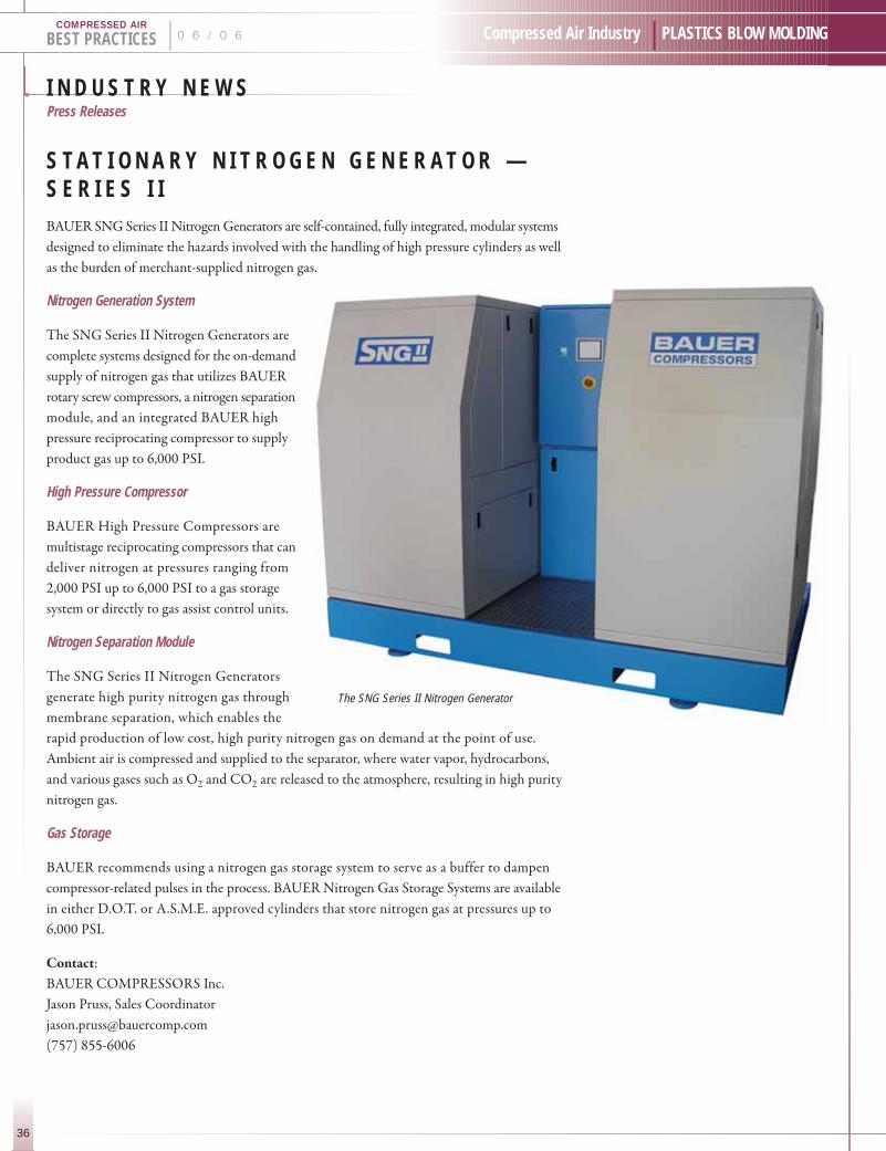
I N D U S T R Y N E W SPress Releases
36
BEST PRACTICES | 0 6 / 0 6 Compressed Air Industry | PLASTICS BLOW MOLDINGCOMPRESSED AIR
S T A T I O N A R Y N I T R O G E N G E N E R A T O R —S E R I E S I IBAUER SNG Series II Nitrogen Generators are self-contained, fully integrated, modular systems
designed to eliminate the hazards involved with the handling of high pressure cylinders as well
as the burden of merchant-supplied nitrogen gas.
Nitrogen Generation System
The SNG Series II Nitrogen Generators are
complete systems designed for the on-demand
supply of nitrogen gas that utilizes BAUER
rotary screw compressors, a nitrogen separation
module, and an integrated BAUER high
pressure reciprocating compressor to supply
product gas up to 6,000 PSI.
High Pressure Compressor
BAUER High Pressure Compressors are
multistage reciprocating compressors that can
deliver nitrogen at pressures ranging from
2,000 PSI up to 6,000 PSI to a gas storage
system or directly to gas assist control units.
Nitrogen Separation Module
The SNG Series II Nitrogen Generators
generate high purity nitrogen gas through
membrane separation, which enables the
rapid production of low cost, high purity nitrogen gas on demand at the point of use.
Ambient air is compressed and supplied to the separator, where water vapor, hydrocarbons,
and various gases such as O2 and CO2 are released to the atmosphere, resulting in high purity
nitrogen gas.
Gas Storage
BAUER recommends using a nitrogen gas storage system to serve as a buffer to dampen
compressor-related pulses in the process. BAUER Nitrogen Gas Storage Systems are available
in either D.O.T. or A.S.M.E. approved cylinders that store nitrogen gas at pressures up to
6,000 PSI.
Contact:
BAUER COMPRESSORS Inc.
Jason Pruss, Sales Coordinator
(757) 855-6006
The SNG Series II Nitrogen Generator

37
Compressed Air Industry | PLASTICS BLOW MOLDING 0 6 / 0 6 | BEST PRACTICESCOMPRESSED AIR
D O N A L D S O N A C Q U I R E S A I R C E L T O S T R E N G T H E N P R O D U C T I O N C A P A B I L I T Y A N D P R O D U C T O F F E R I N G Donaldson Targest the Needs of the Compressed Air & Gas Industry in North America
Minneapolis, MN, USA — January 20, 2006: Donaldson Company, Inc., leading maker of
industrial filtration systems, announced today that it has acquired AirCel Corporation, a privately
held manufacturer of dryers and purification equipment for compressed air and other gases.
“The acquisition of AirCel will dramatically strengthen our production capability and product
offering to the compressed air and gas industry in North America,” Jim Giertz, Senior Vice
President of Donaldson’s Industrial Filtration Solutions business, said. “By manufacturing
in North America we can cut lead times and realize several economic advantages. Our Donaldson
Ultrafilter brand is a strong line of compressed air filtration products, and AirCel’s dryer
products extends our range of both refrigeration and regenerative desiccant dryers for our
North American customers.”
“AirCel’s patented VariCel® refrigerant dryers perfectly complement the Donaldson Ultrafilter
compressed air filters and coalescers,” Mike Zarif, a co-founder and Vice President, of AirCel
Engineering, explained.
AirCel also manufactures N2Cel® nitrogen generators for use in tire inflation. “Using compressed
nitrogen for tire inflation offers both safety and mileage advantages over normal compressed
air,” Robert Olson, co-founder and President of AirCel, stated. “We are pleased to work with
a company that has the global reach and resources of Donaldson as we further develop our
product offering.”
AirCel is based in Maryville, TN with a modern facility that produces a full line of compressed
air/gas purification equipment. AirCel’s refrigerant dryers all use R134a, the latest environmentally
friendly refrigerant that is required to be used in all industrial products by 2010. Both AirCel
and Donaldson are members of the Compressed Air and Gas Institute (CAGI).
For an updated catalog of Donaldson products under the brand names Donaldson Ultrafilter
and Donaldson AirCel call 1-800-543-3634.
Further product information can be found at www.aircelintl.com and http://www.n2cel.com/
Donaldson is a leading worldwide provider of filtration systems and replacement parts. Donaldson is a technology-driven company committed to satisfying customer needs for filtration solutions through innovative researchand development. Donaldson serves customers in the diesel engine and industrial markets including in-plantair cleaning, compressed air and gas purification, power generation, disk drive filtration, off-road equipmentand trucks. Our 11,000 employees contribute to the company’s success at over 30 manufacturing locationsaround the world. Donaldson is a member of the S&P MidCap 400 Index and Donaldson shares are traded on the NYSE under the symbol DCI.

J O B M A R K E TJob Openings in the Compressed Air Industry
38
BEST PRACTICES | 0 6 / 0 6 Compressed Air Industry | PLASTICS BLOW MOLDINGCOMPRESSED AIR
USE COMPRESSEDAIR BEST
PRACTICES TOADVERTISE YOURJOB OPENINGS INTHE COMPRESSED
AIR INDUSTRY!Each month, 1,500 compressed air professionals
receive the magazine. Each job posting ad costs $400.00
which includes on line listings at www.airbestpractices.com
Please send the following information, in a Word Document,
to Patricia Smith at [email protected]
Posting Date:
Position/Title:
Job Description:
Company Contact:
Company Name:
Street: City:
State(Province): Zip Code:
Country: email:
Phone: Fax:

39
Technology | PLASTICS BLOW MOLDING
B E N E F I T S O F A T H R E E - S T A G E R E C I P R O C A T I N G C O M P R E S S O RF O R P E T B L O W M O L D I N G A P P L I C A T I O N SBY JOE MASHBURN
0 6 / 0 6 | BEST PRACTICESCOMPRESSED AIR
Oil-Free, 40 Bar, Ateliers Francois
Since being developed over a century ago, the reciprocating air compressor has been used
in countless applications and proven to be a very reliable piece of equipment. Today, you can
still find these workhorses in operation after as many as 50–75 years of use. Since the mid 1960s,
most plant air applications requiring your typical pressures of 100 to 125 psi were replaced
with the introduction of the rotary screw air compressor. Therefore, the reciprocating compressor
lost market share and now is used in “niche” applications.
One such niche application is the stretch blow molding of PET (polyethylene terephthalate)
plastic containers. Starting in the 1970s, the PET container has succeeded in replacing glass
in a variety of applications including soft drinks, water, food, dairy, medical, household products,
and beer. As more and more products are packaged in PET containers, the blow-molding
machines that produce these containers have become larger and more efficient, with some
machines capable of producing over 60,000 bottles per hour.
There is a variety of stretch blow molding processes used today. The most common is what
is referred to as a two stage process where a plastic preform is made from an injection molder.
This preform, which resembles a large plastic test-tube, is transferred to a stretch blow molding
machine. In this machine, the preform is heated before being placed in the mold. The preform
is then stretched in a vertical direction by a stretch rod and preblown with compressed air
at 175–350 psi (12–25 bar). A second blast of air at pressures up to 580 psi (40 bar) is made
and the bottle is blown to its final shape.
To satisfy both the pressure and capacity requirements for stretch blow molding, the three-
staged, oil-free compressor has been the primary choice for these applications. While some
compressor manufacturers have introduced booster packages and centrifugal
designs, the three-stage reciprocating compressor still maintains advantages
in reliability and power consumption when compared to alternative units.
Three-staged compressors come in a variety of cylinder configurations
including L-design, Y- and W- shapes, as well as horizontally opposed
cylinders. The operation of these is basically the same with each design.
Air is taken through the intake into the first stage piston and compressed
to approximately 60 psi (4 bar). The air is cooled through an inter cooler and
moisture is removed before the air enters the
second stage and compressed to approximately
175–250 psi (12–17 bar). The air is cooled
again through a second intercooler
and is compressed to its final 580
psi (40 bar) discharge pressure in
the third stage cylinder. This air
is then cooled through an after-
cooler so that it can be further
treated through the downstream
drying equipment.
“ the three-stage .
reciprocating
compressor still
maintains advantages
in reliability
and power
consumption when
compared to
alternative units.”

B E N E F I T S O F A T H R E E - S T A G E R E C I P R O C A T I N G C O M P R E S S O RF O R P E T B L O W M O L D I N G A P P L I C A T I O N S
40
BEST PRACTICES | 0 6 / 0 6 Technology | PLASTICS BLOW MOLDINGCOMPRESSED AIR
Compressor With A Rated Capacity Of 777 CFM
The different cylinder configurations that are available can either increase or decrease the
amount of parts within the compressor. The preferred choice for most customers is a design
that reduces the number of moving parts. This will in turn reduce maintenance cost in both
labor and spare parts. The different designs can also dramatically affect the number of valves
that the compressor utilizes. With some compressors requiring twice the number of valves than
others, the compressor with fewer valves to maintain will again reduce the cost of maintaining
the compressor. Finally, the design and size of the cylinders will determine the speed of the
compressor. Most customers prefer a compressor with a slow RPM to reduce the wear and tear
on the moving components. It is important to note that if a compressor operates at 250 RPMs
more than a competitor’s model, the faster compressor will turn 15,000 more revolutions in one
(1) hour, 360,000 more in a 24-hour period, and 120,000,000 more in one year (8,000-hours).
The manufacturers of PET stretch blow molding machines specify
that the air must be “oil-free.” Most three-stage compressor suppliers
utilize a PTFE or Teflon-coated material for their compression and
wear rings. This ring material has been proven both dependable and
reliable in a variety of applications requiring oil-free compressors
including medical, chemical, and food industries. There are some
manufacturers that offer lubricated screw/booster systems for PET
applications. These types of systems are not recommended by the blow
mold machine manufacturers due to possible contamination of their
equipment as well as to the bottles that are produced.
The blow molding machines also require dry air to a pressure dewpoint
of 38ºF (3ºC) with removal of particles “one micron and larger.”
To meet this air quality specification, refrigerated air dryers and filtration
are also typically provided by the compressor manufacturer as part
of their package. The refrigerated air dryer, located downstream of the
compressor and receiver, will maintain a consistent pressure dewpoint
for the system. Some competing manufacturers offer oil-free rotary
screw/booster packages with a heat of compression dryer between
their oil-free, low-pressure compressor and booster. In some cases,
these types of dryers operate below their rated capacity, therefore
lowering the heat of compression that is normally utilized to perform
regeneration of the desiccant. This can cause a rise in moisture within
the air stream to the point that the specified dewpoint to the blow
molder will not be achieved. Moisture within the system will cause
defects in the bottle and, with some systems, shut down the entire
production line as a result of high dew point alarms from system-
installed dew point monitors.
Three-Stage Ateliers Francois
41
Technology | PLASTICS BLOW MOLDING 0 6 / 0 6 | BEST PRACTICESCOMPRESSED AIR
Compressor Installation
With the advancement of better skid design and anti-vibration mounts,
most three-stage compressors do not require an expensive foundation
or grouting during installation. Typically, most manufactures require
only a level floor that can handle the static weight of the compressor.
Units can be purchased with many of the components, including
aftercoolers and receivers, prepiped and mounted on the compressor
skid. This makes installation much easier and keeps the cost of installation
low. Along with the before mentioned drying and filtration systems,
most compressor manufacturers offer the option of a cooling water
system to supply the cooling water for the compressor.
Finally, the potential power cost savings of a three-stage reciprocating
compressor versus that of a booster package is quite significant. The
booster packages typically use an oil-free rotary screw compressor
to supply low pressure air to the booster. Since the oil-free rotors cannot
be in direct contact, these compressors offer low capacity/power ratios
when compared to an oil-free piston compressor. The energy required
for the rotary screw/booster systems is typically 12–15% higher than
that of a three-stage compressor. Furthermore, since the majority
of the piston compressors operate with load/no load controls, some
manufactures utilize only 10–12% of the full load shaft power when
operating at no load. This can help lower the power cost versus that of
a screw/booster system when the system is not operating at full capacity.
Reciprocating air compressors have proven their reliability since their
introduction over a century and a half ago. In particular, the three-
stage oil-free compressor has consistently performed and maintained
its reliability for PET blow molding plants throughout the world. Its
robust design and potential power savings over a booster system helps
keep operating costs to a minimum. Without question, the three-
stage reciprocating compressor is the preferred compressor for such
a demanding application.
For more information contact: Joe Mashburn, AF Compressors USA, Phone (770) 214-2241 or visit www.afcompressors.com.
Note: AF Compressors USA is the U.S. subsidiary of the Belgium-based firm, AteliersFrancois, which has over 100 years experience in manufacturing compressed airequipment. Today, we specialize in the production of 40-bar, oil-free air compressorpackages with capacities up to 3,058 CFM for the PET blow molding industry.
SUBSCRIBE NOW!C O M I N G E D I T I O N S !
Energy Efficiency, Printing, Hospitals, Food Processing,Concrete, Manufacturing Productivity
I D E A L F O R :INDUSTRY:
Plant Engineers, Plant Managers & Maintenance Managers
COMPRESSOR DISTRIBUTORS:Every Branch Location
MANUFACTURERS:Management, Sales, Marketing & Engineering
Rates: 12-month SubscriptionNumber of
Subscriptions 1-10 11-19 20-49 50+
U.S. $175.00 $160.00 $140.00 $130.00
Canada $185.00 $170.00 $150.00 $140.00
International $220.00 $205.00 $195.00 $180.00
3 W A Y S T O S U B S C R I B E :*
1.) Visit www.airbestpractices.com and use your Visa/Mastercard
2.) Email us at [email protected] mail your check.
3.) Mail your information and check to:Compressed Air Best Practices161 Clubhouse CircleFairhope, AL 36532
Checks should be made out to “Smith Onandia Communications, LLC ”. Questions call Patricia Smith: 251-510-2598.
*Information Required:
First Name:
Last Name:
Company Name:
Street: City:
State(Province): Zip Code:
Country: email:
Phone: Fax:

H I G H - P R E S S U R E D R Y E R SBY TIM FOX P.E.
42
BEST PRACTICES | 0 6 / 0 6 Technology | PLASTICS BLOW MOLDINGCOMPRESSED AIR
Industry’s increasing demand for clean, reliable sources of high pressure compressed air requiresthat system designers become more educated in dehydration and filtration at these elevatedoperating pressures. Control valves and motion controllers used in PET bottling and other highpressure applications use smaller orifices and are made with higher precision tolerances thantheir low pressure counterparts. It is critical that the air flowing through these components befree of all liquids, oil, and particulates. This article will describe where these contaminates originate,and how to eliminate them.
Note that the use of the term “high pressure air” will refer to systems operating at 500 psig to 700psig (35 barg to 48 barg). By contrast, “low pressure air” or “general plant air” is assumed to be inthe 100 psig to 125 psig (7 barg to 9 barg) range.
Sources of Contamination
The three (3) primary contaminants of concern for compressed air systems are moisture, oil,
and solid particulates.
Moisture: As with low pressure air generation, moisture is introduced into the high pressure
air system at the compressor intake. Ambient water vapor, commonly expressed as relative
humidity, is ingested with the surrounding air. Compressor inlet filtration cannot capture this
water vapor. As this mixture of air and water vapor is compressed, the temperature increases,
aiding the air’s ability to “hold” water vapor. Conversely, the increase in pressure decreases
the air’s capacity to retain the water in vapor form. The influence of temperature overrides
the pressure effects and the moisture remains as a vapor throughout the compression process.
Problems arise as the air is cooled in the subsequent system aftercoolers and downstream piping,
and liquid water is formed by condensation.
Oil: Hydrocarbons and lubricants are introduced during the compression process. Oils are
supplied to the machine’s bearing and sealing surfaces and small amounts are swept away by
the compressed air. Integrated air/oil separators (if present) are not 100% efficient in capturing
the entrained oil aerosols. If present in the ambient air, additional hydrocarbon contamination,
in vapor form, may also be admitted at the compressor inlet. As with water, these vapors will
condense into liquids in the compression and subsequent cooling process. Compressor inlet
filtration does little to prevent this at the source.
Particulates: Solid contaminants have three (3) sources in a typical installation: ambient air,
the compressor internals, and the piping/accessory components. Compressor inlet filtration
will prevent many environmental particulates from entering the system. Therefore, prompt
and regular inlet filter maintenance is imperative for optimum system efficiency. While normal
wear of the metallic parts within the compressor generates a minor source of solid contaminants,
the primary source of system particulate contamination is the corrosion and erosion within
the piping system. System materials of construction, piping size, and the piping layout must
be carefully considered.
“ It is critical .
that the air
flowing through
these components
be free of all
liquids, oil,
and particulates.”

43
Technology | PLASTICS BLOW MOLDING 0 6 / 0 6 | BEST PRACTICESCOMPRESSED AIR
System Design Considerations
In order to properly construct a compressed air dehydration and
filtration system, the designer must have a good understanding of
the operating conditions—inside the piping system as well as the
surrounding ambient. The following questions should be answered:
p What are the maximum and minimum ambienttemperatures at the compressor intake?
p What is the expected maximum ambient relativehumidity at these temperatures?
p What is the minimum ambient temperature of the piping system?
p What level of compressed air dryness is needed?Is the absence of any liquid all that is required,or does the process demand the absence of water vapor?
p What level of particulate and oil contaminationcan be tolerated?
And finally,
p What type of compressed air dryer/filtration system will satisfy my requirements?
Moisture Elimination
Understanding the relationship between the compressed air’s ability
to hold water vapor (not condense into troublesome liquid) and its
temperature and pressure is the key to designing an economical and
effective drying system. Industry typically expresses the air’s moisture
holding capacity as its “pressure dew point,” or the temperature at which
the air becomes saturated with water vapor at a given pressure.
If the air temperature drops below this value, moisture will condense.
Much has been written about these values for typical low pressure
systems. The values change dramatically for the high pressure
applications. Table 1 lists pressure dew point temperatures at different
operating pressures for various ambient temperatures and relative
humidities. Note the increase in pressure dew point as the system
operating pressure increases. Table 1 can be used to understand the
ambient conditions at which liquid will form in the system piping.
Once the desired level of dryness for the system has been determined,
equipment selection needs to be considered.
Types of Compressed Air Dryers
Refrigerated: By far, the most common compressed air dryer used
in high pressure systems is the refrigerated dryer. This product uses a
refrigeration system and an air to refrigerant heat exchanger to cool
the compressed air and condense the unwanted water vapor into liquid.
The liquid is then separated from the compressed air stream and
removed from the piping system with a drain valve. The air is typically
precooled before entering the air to refrigerant heat exchanger by
employing an integral air to air heat exchanger using the cool exiting
air. The air to air heat exchanger allows the use of smaller refrigeration
systems and produces warm, dry air at the outlet of the dryer. Refrigerated
dryers come completely assembled in a cabinet, requiring only air,
power, and drain connections for installation. The refrigeration systems
are available in either air-cooled or water-cooled versions, requiring
the designer to consider the ambient temperature at the installation
site and/or the cooling water temperature when sizing this equipment.
Table 1. System Pressure Dew Point Temperature
SYSTEMPRESSURE 0 PSIG 50 PSIG 100 PSIG 250 PSIG 500 PSIG 600 PSIG 700 PSIG
25% r.h. -12 °F 20 °F 34 °F 55 °F 73 °F 78 °F 82 °F20°F 50% r.h. 3 °F 37 °F 52 °F 75 °F 95 °F 100 °F 104 °F
75% r.h. 12 °F 48 °F 63 °F 88 °F 108 °F 114 °F 119 °F25% r.h. 7 °F 42 °F 57 °F 81 °F 101 °F 106 °F 111 °F
40°F 50% r.h. 23 °F 61 °F 77 °F 103 °F 125 °F 131 °F 137 °F75% r.h. 33 °F 73 °F 90 °F 117 °F 141 °F 147 °F 153 °F25% r.h. 24 °F 62 °F 79 °F 105 °F 127 °F 133 °F 139 °F
60°F 50% r.h. 41 °F 83 °F 101 °F 130 °F 155 °F 161 °F 167 °F75% r.h. 52 °F 96 °F 115 °F 146 °F 172 °F 179 °F 185 °F25% r.h. 41 °F 83 °F 101 °F 129 °F 154 °F 161 °F 167 °F
80°F 50% r.h. 60 °F 105 °F 125 °F 157 °F 184 °F 192 °F 199 °F75% r.h. 71 °F 119 °F 140 °F 174 °F 203 °F 212 °F25% r.h. 58 °F 102 °F 123 °F 154 °F 181 °F 189 °F 195 °F
100°F 50% r.h. 78 °F 127 °F 149 °F 184 °F75% r.h. 91 °F 143 °F 166 °F 203 °FAM
BIEN
T TE
MPE
RATU
RE A
ND R
ELAT
IVE
HUM
IDIT
Y

H I G H - P R E S S U R E D R Y E R S
44
BEST PRACTICES | 0 6 / 0 6 Technology | PLASTICS BLOW MOLDINGCOMPRESSED AIR
Refrigerated compressed air dyers can achieve pressure dew points
as low as 39˚F (3˚C). Therefore, as long as the compressed air piping
downstream of the dryer is not exposed to temperatures below 39˚F
(3˚C), liquid will not form in the piping. The operating costs for this
system are simply the power consumed by the refrigeration system
and any pressure drop through the heat exchangers and moisture
separator. As with all high pressure compressed air system components,
care must be taken to ensure that the dryer selected is designed for the
maximum expected operating temperature and pressure of the system.
Sizing factors for temperature, pressure, and ambient temperature are
supplied by the manufacturer.
Desiccant Dryers
If the piping system or manufacturing process requires pressure dew
points below 39˚F (˚C), then desiccant dryers must be considered.
Desiccant dryers use adsorbent materials—typically activated alumina,
silica gel, or molecular sieve—to remove the moisture present.
The water vapor is transferred from the compressed air stream
to the adsorbent by taking advantage of the desiccant’s high affinity
for water molecules. No cooling or condensation takes place in this
process. The desiccant bed is periodically regenerated in order to
remove the adsorbed water. Typically, this regeneration is done by
using a portion of the dried air, reducing it to atmospheric pressure
(increasing its moisture holding capacity), and flowing it over the
moisture-laden desiccant. Two towers of desiccant, a system of switching
valves, and a timer complete the design so that one tower can stay
on-line and dry the compressed air while the second tower is being
regenerated. This method ensures a continuous flow of dry compressed
air downstream.
Desiccant dryers achieve pressure dew points down to -40˚F (-40˚C)
and can be designed for -100˚F (-73˚C) pressure dew points. The cost
of operating this type of equipment is calculated by considering the
amount of dried compressed air used for regeneration. Other forms
of regeneration include heating the purge air (increasing its moisture
holding capacity) and using heated ambient air and a blower. Initial
capital costs versus operating costs must be considered when choosing
the optimum system. In general, desiccant dryers have higher initial
costs and operating costs than refrigerated dryers.
2,500 PSI Rated Desiccant Dryer in Production
725 PSI Rated Refrigerated Dryer
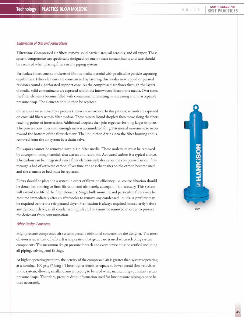
45
Technology | PLASTICS BLOW MOLDING 0 6 / 0 6 | BEST PRACTICESCOMPRESSED AIR
Filter
Elimination of Oils and Particulates
Filtration: Compressed air filters remove solid particulates, oil aerosols, and oil vapor. These
system components are specifically designed for one of these contaminants and care should
be executed when placing filters in any piping system.
Particulate filters consist of sheets of fibrous media material with predictable particle capturing
capabilities. Filter elements are constructed by layering this media in wrapped or pleated
fashion around a perforated support core. As the compressed air flows through the layers
of media, solid contaminants are captured within the interwoven fibers of the media. Over time,
the filter elements become filled with contaminant, resulting in increasing and unacceptable
pressure drop. The elements should then be replaced.
Oil aerosols are removed by a process known as coalescence. In this process, aerosols are captured
on crosslaid fibers within filter medias. These minute liquid droplets then move along the fibers
reaching points of intersection. Additional droplets then join together, forming larger droplets.
The process continues until enough mass is accumulated for gravitational movement to occur
toward the bottom of the filter element. The liquid then drains into the filter housing and is
removed from the air system by a drain valve.
Oil vapors cannot be removed with plain filter media. These molecules must be removed
by adsorption using materials that attract and retain oil. Activated carbon is a typical choice.
The carbon can be integrated into a filter element-style device, or the compressed air can flow
through a bed of activated carbon. Over time, the adsorbent sites on the carbon become used,
and the element or bed must be replaced.
Filters should be placed in a system in order of filtration efficiency; i.e., course filtration should
be done first, moving to finer filtration and ultimately, adsorption, if necessary. This system
will extend the life of the filter elements. Single bulk moisture and particulate filters may be
required immediately after an aftercooler to remove any condensed liquids. A prefilter may
be required before the refrigerated dryer. Prefiltration is always required immediately before
any desiccant dryer, as all condensed liquids and oils must be removed in order to protect
the desiccant from contamination.
Other Design Concerns
High pressure compressed air systems present additional concerns for the designer. The most
obvious issue is that of safety. It is imperative that great care is used when selecting system
components. The maximum design pressure for each and every device must be verified, including
all piping, valving, and fittings.
At higher operating pressures, the density of the compressed air is greater than systems operating
at a nominal 100 psig (7 barg). These higher densities equate to lower actual flow velocities
in the system, allowing smaller diameter piping to be used while maintaining equivalent system
pressure drops. Therefore, pressure drop information used for low pressure piping cannot be
used accurately.

H I G H - P R E S S U R E D R Y E R S
46
BEST PRACTICES | 0 6 / 0 6 Technology | PLASTICS BLOW MOLDINGCOMPRESSED AIR
Typical High Pressure System Layout
Figure 4 suggests a dehydration and filtration design for a high pressure compressed air system
(500 psig to 700 psig) using a refrigerated dryer. For desiccant systems, Figure 5 shows the
proper component arrangement. Note that these figures assume that oil vapor removal is
required. For applications where this is not necessary, simply remove the oil vapor filter.
In some plant systems, point-of-use high pressure compressed air is generated by compressing
general plant air (at 100 psig) in a booster compressor. The question arises: if the general
plant air has already been cleaned and dried, do I need additional drying and filtration?
The answer to this question depends on the final boosted pressure and the desired dryness
of the high pressure air. Table 2 shows the pressure dew point temperature of high pressure
air generated from a plant air supply that has been dried to a 39˚F (3˚C) pressure dew point.
As the boosted pressure increases, the saturation temperature of the compressed air increases.
In general, for a piping system to remain liquid-free at ambient temperatures near 65˚F (18˚C),
additional high pressure drying equipment is needed for boosted pressures in excess of 300
psig (21 barg). Figures 6 and 7 suggest component layouts for such an application.
Figure 4.
Figure 5.
Table 2. System Pressure Dew Point Temperatures at Various Boosted Pressures
SYSTEMPRESSURE 100 PSIG 200 PSIG 300 PSIG 400 PSIG 500 PSIG 600 PSIG 700 PSIG
PressureDew Point 39 °F 56 °F 66 °F 74 °F 80 °F 85 °F 89 °F

47
Technology | PLASTICS BLOW MOLDING 0 6 / 0 6 | BEST PRACTICESCOMPRESSED AIR
Typical Booster System Layout
Figure 6 suggests a dehydration and filtration design for boosting clean, dry 100 PSIG Plant
air using a refrigerated dryer. For desiccant systems, Figure 7 shows the proper component
arrangement. Note that these figures assume that oil vapor removal is required. For applications
where this is not necessary, simply remove the oil vapor filter.
Summary
To eliminate unwanted moisture, oil, and particulates from high pressure compressed air systems,
the design presents many of the same issues as a general plant air supply. By carefully defining
the desired compressed air purity, components can be properly selected and placed appropriately
in order to achieve an efficient and reliable solution. Higher operating pressures will increase
the dew point temperature for a given moisture content as compared to a low pressure application.
However, the equipment and technology for dehydration and filtration equipment is nearly
the same. Follow the guidelines set forth here and use good engineering practices when making
the equipment selections. A reliable supply of clean and dry high pressure compressed air will
serve your manufacturing processes for many years to come.
For more information contact: Tim Fox, Manager Research and Development, SPX Dehydration & ProcessFiltration. Phone (724) 873-8443 or visit www.spxdehydration.com.
Figure 6.
Figure 7.

48
BEST PRACTICES | 0 6 / 0 6 Technology | PLASTICS BLOW MOLDING
Essence Bottling in Albuquerque, NM
processes 5,000 bottles of spring water
per hour through its 20,000 sq. ft. facility.
Business was good and growing, but there
were no local bottle blowmolders in the
region. Purchasing plastic bottles from
out of state manufacturers and paying freight
was becoming increasingly expensive and
problematic. Essence decided to invest in
blowmolding machinery and make their bottles
on-site. Since blowmolding relies heavily
on compressed air, Essence began plans
to upgrade their compressed air system.
The current process air needs for bottling
were minimal and were met by a small,
but noisy, 15 HP rotary screw compressor.
However, they needed more than just
additional capacity for the blowmolding
process. The new air system had to provide
a reliable source of clean, dry air and a
significant portion of that air would need to
be at a much higher pressure. After developing
the base equipment specifications, Essence
contacted their existing air compressor vendors.
Larry and Gary Trujillo from Advanced Compressor Systems in Albuquerque, NM reviewed
the specifications and provided a quotation for the required equipment, plus the plumbing,
piping, and installation factors. Because Albuquerque sits at 5,000 ft., there were special high
altitude considerations for the system. Larry recommended a 250 HP direct drive rotary screw
compressor, a high-pressure refrigerated dryer, and a booster compressor, as well as schedule
80 pipe and fittings. The rotary screw compressor would provide over 800 cfm at a base pressure
of 190 psig. While the air compressor featured a built-in aftercooler, the refrigerated dryer
would further cool the air and remove moisture to a 39˚F dew point before the air entered
the booster.
More Than They Bargained for…
The booster is a reciprocating compressor designed to further compress air and “boost” the
pressure at the point of use. Increasing the pressure for only a portion of the compressed air
is considerably more efficient than building an entire high pressure system and regulating the
pressure back down.
Patrick Chavez and John Wilson inspect their new ESD 250 and discuss its smooth, quiet operation.
Once the ambient air is compressed in the main com-pressor, the Booster uses pistons to boost the pres-sure to 590 psig. This two-stage system is ideal andeconomical for PET bottling applications.
F R O M B O T T L I N G T O B L O W M O L D I N GNew Mexico bottler gets hard dollar savings and new business from new blowmolding lineBY ANGELA KELLY, KAESER COMPRESSORS, INC.
COMPRESSED AIR

49
Technology | PLASTICS BLOW MOLDING
The blowmolding application required
a reliable, constant pressure of 590 psig.
A decision had to be made on whether to
purchase a high pressure compressor or go
with the booster system. A couple of factors
helped shape the decision. “The owner wanted
quiet,” said Larry Trujillo, “and the rotary
screw compressor’s split cooling air flow
design and low noise radial fans provide
incredibly quiet operation.” Further, there
was no additional investment required for
special foundations, a separate compressor
room, or extensive noise attenuating fixtures
as required by many large high pressure systems.
The Trujillo brothers designed the system
layout with the rotary screw compressor in
front of the booster, allowing it to act as a
noise buffer. Plus, the booster compressor is
water-cooled æ another sound-dampening
factor. The plant layout necessitated the air
system’s placement less than 50 feet from the
blowmolding machine and, due to the open
layout of the shop, Essence was concerned
about noise. They would be pleasantly surprised.
Albert Murray, Chief Executive Officer and John Wilson, Executive Vice President for Essence
accepted the Trujillo brothers’ proposal and a date for the installation was set. Working around
the plant’s production schedule, the new system was installed without shutting down operations
and the moment of truth arrived. Murray came out to view the new system and said “Well,
let’s turn it on!” But much to his surprise the system was already running. Comparing the
rotary screw 250 HP air compressor and booster to the existing 15 HP, Wilson said, “It’s more
than ten times bigger, but ten times quieter!”
The new compressed air system consists of a 250 hp direct drive rotary screw compressor, a 60 hpreciprocating booster compressor, and a high pressure refrigerated dryer.
“It’s more than .
ten times bigger,
but ten times
quieter!”
0 6 / 0 6 | BEST PRACTICESCOMPRESSED AIR
Essence found it could produce its own bottles at a significant cost savings.

F R O M B O T T L I N G T O B L O W M O L D I N GNew Mexico bottler gets hard dollar savings and new business from new blowmolding line
50
BEST PRACTICES | 0 6 / 0 6 Technology | PLASTICS BLOW MOLDINGCOMPRESSED AIR
Essence is up and running with its new
blowmolding line and saving $0.03 per bottle
— that’s over $1,200 per 8-hour shift —
certainly enough to justify the investment
in new equipment! The new compressed air
system supplies process air for the entire facility.
The booster system ensures a reliable source
of clean, dry air for the bottles, keeping quality
control issues to a minimum and reducing
product rejection. “Zero problems” is how
Wilson described the new air system. In fact,
the new line is so successful that the entire
focus of the business is changing from bottling
to blowmolding, filling a void in the region
for quality plastic bottles. Watch for a second
Essence facility opening soon!
For more information contact: Angela Kelly, PublicRelations, Kaeser Compressor. Phone 800-777-7873or visit www.kaeser.com.
Starting with a small plastic pellet and a mold, these bottles are formed by injecting clean, dry compressed air at 590 psig.
All Kaeser photo credits: Ivy Associates
The blow molding system produces over 40,000 bottles in one eight hour shift.
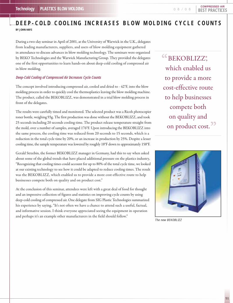
51
Technology | PLASTICS BLOW MOLDING
D E E P - C O L D C O O L I N G I N C R E A S E S B L O W M O L D I N G C Y C L E C O U N T S BY JOHN HAYS
0 6 / 0 6 | BEST PRACTICESCOMPRESSED AIR
During a two-day seminar in April of 2001, at the University of Warwick in the U.K., delegates
from leading manufacturers, suppliers, and users of blow molding equipment gathered
in attendance to discuss advances in blow molding technology. The seminars were organized
by BEKO Technologies and the Warwick Manufacturing Group. They provided the delegates
one of the first opportunities to learn hands-on about deep-cold cooling of compressed air
in blow molding.
Deep-Cold Cooling of Compressed Air Increases Cycle Counts
The concept involved introducing compressed air, cooled and dried to - 42°F, into the blow
molding process in order to quickly cool the thermoplastics leaving the blow molding machine.
The product, called the BEKOBLIZZ, was demonstrated in a trial blow molding process in
front of the delegates.
The results were carefully timed and monitored. The selected product was a Ricoh photocopier
toner bottle, weighing 93g. The first production was done without the BEKOBLIZZ, and took
25 seconds including 20 seconds cooling time. The product release temperature straight from
the mold, over a number of samples, averaged 176°F. Upon introducing the BEKOBLIZZ into
the same process, the cooling time was reduced from 20 seconds to 15 seconds, which is a
reduction in the total cycle time by 20%, or an increase in production by 25%. Despite a lesser
cooling time, the sample temperature was lowered by roughly 18°F down to approximately 158°F.
Gerald Strzebin, the former BEKOBLIZZ manager in Germany, had this to say when asked
about some of the global trends that have placed additional pressure on the plastics industry,
“Recognizing that cooling times could account for up to 80% of the total cycle time, we looked
at our existing technology to see how it could be adapted to reduce cooling times. The result
was the BEKOBLIZZ, which enabled us to provide a more cost-effective route to help
businesses compete both on quality and on product cost.”
At the conclusion of this seminar, attendees were left with a great deal of food for thought
and an impressive collection of figures and statistics on improving cycle counts by using
deep-cold cooling of compressed air. One delegate from SIG Plastic Technologies summarized
his experience by saying, “It’s not often we have a chance to attend such a useful, factual,
and informative session. I think everyone appreciated seeing the equipment in operation
and perhaps it’s an example other manufacturers in the field should follow.”The new BEKOBLIZZ
“BEKOBLIZZ®, .
which enabled us
to provide a more
cost-effective route
to help businesses
compete both
on quality and
on product cost.”

D E E P - C O L D C O O L I N G I N C R E A S E S B L O W M O L D I N G C Y C L E C O U N T S
52
BEST PRACTICES | 0 6 / 0 6 Technology | PLASTICS BLOW MOLDINGCOMPRESSED AIR
Provides dew points to -100˚F
Two refrigeration compressors provide deep-cold cooling
Improvements in Quality
Since the introduction of this new technology, the majority of blow molders who are using
deep-cold cooling of compressed air have found their molded parts quality is better than
before, in addition to seeing a significant impact on cycle time. This means less re-grind, more
parts passing quality control checks, and lower JIT intervals. Therefore, the actual benefit to
the user is two-fold and the economic payback is twice as fast as it would be if you were to
calculate only the reduction in cycle time. This was proven after further reviewing the results
from a number of BEKOBLIZZ installations, covering a variety of molded part shapes and
sizes from a one liter bottle to a 1,000 liter tank. Across the applications surveyed, the break-
even period was remarkably similar, ranging from five months to just under eight months.
Replacing Liquid Gas for Cooling
Deep-cold cooling of compressed air provides a safe and lower-cost cost alternative to those
using liquid gas or large amounts of refrigerants to cool thermo plastics. Using environmentally
friendly and economical off-the-shelf refrigeration compressors and refrigerants, the product
functions as follows:
1. Compressed air enters the first refrigerant circuit consisting of anexchanger, condenser, compressor, etc., where it is precooled to 41°F.
2. The air then enters a dual filtration system where condensed moisture and oil aerosols are removed from the air.
3. Air then enters a pressure-swing desiccant dryer which can be set topressure dew points of -100°F. This pressure dew point is controlled,where a high dew point alarm is constantly monitoring the condition of the air at the desiccant stage.
4. Solid particulates, to 1 micron, are then removed by a filter.
5. Extremely dry air now enters the second refrigerant circuit, which is configured the same as the first but using components with design tolerances for the now very cold air, where the air temperature is lowered to up to -48°F. No moisture condensation occurs due to the extremely low pressure dew point of the air.
6. Air is now ready to be introduced into the blow molding machine wherethe blow pin can blow it on the thermoplastics for deep-cold cooling.
For more information contact: John Hays, BEKO Technologies Corporation. Phone (704) 663-6621 or visitwww.bekousa.com.
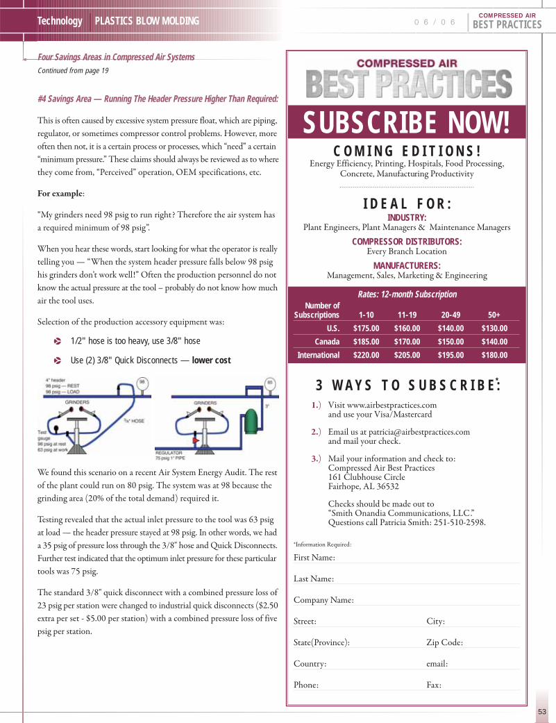
53
Technology | PLASTICS BLOW MOLDING 0 6 / 0 6 | BEST PRACTICESCOMPRESSED AIR
SUBSCRIBE NOW!C O M I N G E D I T I O N S !
Energy Efficiency, Printing, Hospitals, Food Processing,Concrete, Manufacturing Productivity
I D E A L F O R :INDUSTRY:
Plant Engineers, Plant Managers & Maintenance Managers
COMPRESSOR DISTRIBUTORS:Every Branch Location
MANUFACTURERS:Management, Sales, Marketing & Engineering
Rates: 12-month SubscriptionNumber of
Subscriptions 1-10 11-19 20-49 50+
U.S. $175.00 $160.00 $140.00 $130.00
Canada $185.00 $170.00 $150.00 $140.00
International $220.00 $205.00 $195.00 $180.00
3 W A Y S T O S U B S C R I B E :*
1.) Visit www.airbestpractices.com and use your Visa/Mastercard
2.) Email us at [email protected] mail your check.
3.) Mail your information and check to:Compressed Air Best Practices161 Clubhouse CircleFairhope, AL 36532
Checks should be made out to “Smith Onandia Communications, LLC ”. Questions call Patricia Smith: 251-510-2598.
*Information Required:
First Name:
Last Name:
Company Name:
Street: City:
State(Province): Zip Code:
Country: email:
Phone: Fax:
#4 Savings Area — Running The Header Pressure Higher Than Required:
This is often caused by excessive system pressure float, which are piping,
regulator, or sometimes compressor control problems. However, more
often then not, it is a certain process or processes, which “need” a certain
“minimum pressure.” These claims should always be reviewed as to where
they come from, “Perceived” operation, OEM specifications, etc.
For example:
“My grinders need 98 psig to run right? Therefore the air system has
a required minimum of 98 psig”.
When you hear these words, start looking for what the operator is really
telling you — “When the system header pressure falls below 98 psig
his grinders don’t work well!” Often the production personnel do not
know the actual pressure at the tool – probably do not know how much
air the tool uses.
Selection of the production accessory equipment was:
p 1/2" hose is too heavy, use 3/8" hose
p Use (2) 3/8" Quick Disconnects — lower cost
We found this scenario on a recent Air System Energy Audit. The rest
of the plant could run on 80 psig. The system was at 98 because the
grinding area (20% of the total demand) required it.
Testing revealed that the actual inlet pressure to the tool was 63 psig
at load — the header pressure stayed at 98 psig. In other words, we had
a 35 psig of pressure loss through the 3/8" hose and Quick Disconnects.
Further test indicated that the optimum inlet pressure for these particular
tools was 75 psig.
The standard 3/8" quick disconnect with a combined pressure loss of
23 psig per station were changed to industrial quick disconnects ($2.50
extra per set - $5.00 per station) with a combined pressure loss of five
psig per station.
Four Savings Areas in Compressed Air SystemsContinued from page 19
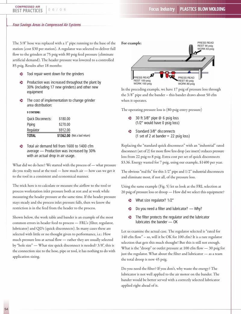
Four Savings Areas in Compressed Air Systems
54
BEST PRACTICES | 0 6 / 0 6 Focus Industry | PLASTICS BLOW MOLDINGCOMPRESSED AIR
The 3/8" hose was replaced with a 1" pipe running to the base of the
station (cost $30 per station). A regulator was selected to deliver full
flow to the grinders at 75 psig with 80 psig feed pressure (eliminate
artificial demand). The header pressure was lowered to a controlled
85 psig. Results after 18 months:
p Tool repair went down for the grinders
p Production was increased throughout the plant by30% (including 17 new grinders) and other newequipment
p The cost of implementation to change grinderarea distribution:
9 STATIONS:
Quick Disconnects: $180.00Piping $270.00Regulator $912.00TOTAL $1362.00 (Not a bad return)
p Total air demand fell from 1600 to 1400 cfmaverage — Production was increased by 30%with an actual drop in air usage.
What did we do here? We started with the process of — what pressure
do you really need at the tool — how much air — how can we get it
to the tool in a consistent and economical manner.
The trick here is to calculate or measure the airflow to the tool or
process workstation inlet pressure both at rest and at work while
measuring the header pressure at the same time. If the header pressure
stays steady and the process inlet pressure falls, then we know the
restriction is in the feed from the header to the process.
Shown below, the work table and bander is an example of the most
common errors in header feed to process — FRL’s (filter, regulator,
lubricator) and QD’s (quick disconnects). In many cases these are
selected with little or no thought given to performance, i.e.: How
much pressure loss at actual flow — rather they are usually selected
by “hole size” — What size quick disconnect is needed? 3/8", this is
the connection size to the hose, pipe or tool, it has nothing to do with
application sizing.
For example:
In the preceding example, we have 17 psig of pressure loss through
the 3/8” pipe and the bander – this bander draws about 50 cfm
when it operates.
The operating pressure loss is (80-psig-entry pressure)
p 30 ft 3/8” pipe @ 6 psig loss (1/2” would have 0 psig loss)
p Standard 3/8” disconnects (1 set of 2 at bander = 22 psig loss)
Replacing the “standard quick disconnect” with an “industrial” rated
disconnect (set of 2) for more flow/less drop (see insert) reduces pressure
loss from 22 psig to 8 psig. Extra cost per set of quick disconnects
$3.36. Energy wasted for 7 psig, using our example, $1400 per year.
The obvious “real fix” for this 1/2” pipe and 1/2” industrial disconnects
and eliminate most, if not all, of the pressure loss.
Using the same example (Fig. 5) let us look at the FRL selection at
20 psig of pressure loss or droop — How did we select this equipment?
p What size regulator? 1/2”
p Do you need a filter and lubricator? — Why?
p The filter protects the regulator and the lubricatorlubricates the bander — OK
Let us examine the actual case. The regulator selected is “rated for
140 cfm flow” – so, will it be OK for 100 cfm? It is a rare regulator
selection that gets this much thought! But this is still not enough.
What is the “droop” or outlet pressure at 100 cfm flow — 30 psig for
just the regulator. What about the filter and lubricator — as a team
the total droop is now 45 psig.
Do you need the filter? If you don’t, why waste the energy? The
lubricator is not well applied to the air motor on the bander. The
bander would be better served with a correctly selected lubricator
applied right ahead of it.

55
Focus Industry | PLASTICS BLOW MOLDING 0 6 / 0 6 | BEST PRACTICESCOMPRESSED AIR
Summary
All too often FRL’s quick disconnects, and feed lines to the process
are selected by size, convenience, and price with little or no regard
for flow and or pressure loss allowance. The cornerstone of any effective
compressed air energy savings program on the distribution or process
side is to identify the LOWEST effective pressure that will run the
process at optimum performance. Programs can then be implemented
to deliver this at the lowest possible cost and pressure loss. Utilizing
all the tools we have, piping, connections, pressure / flow controllers,
appropriate storage, etc.
When you have a plant with a low-pressure problem, “Because the area
is too far away from the compressors”? — most of the time (90 – 95%)
we find the problem is NOT in the header, but in the feeds from the
header. Headers should be sized to 20 – 30 fps or higher velocity and
looped whenever possible.
SUPPOSE THERE REALLY IS A HIGH PRESSURE NEED:
You may want to supply the local high-pressure need with a secondary
smaller high-pressure unit or an appropriate “booster” rather than drive
whole system higher. The filter press shown here required 100 psig
minimum while the rest of the chemical plant ran well on 90 psig.
In this situation a Compressed Air Audit, always checks whether the
high-pressure air is actually required. If it is, the next question is, can we
modify the process to lower pressure air? For example: change to a larger
diameter air cylinder! If not, there are several alternate ways to handle
this situation.
For example:
The first job is to calculate or MEASURE the amount of air (cfm),
the required pressure (psig), and the cycle time (time on/time off ).
With this data, we can calculate the most effective and efficient answer:
p Use a separate air compressor and system to supply dedicated air to the process
p Use a booster compressor or hydraulic booster to supply high-pressure air.
p Use storage
Summary
I believe you can see this journey through the system has been one of
INVESTIGATION — We observe measure, calculate, test, and treat
the compressed air like a expensive utility — WHICH IT IS!
Identify its cost and apply it to a controllable production cost to a
process, just as you would with electricity, steam, etc.
Compressed air is a Very “ENERGY EXPENSIVE” utility — 7 to 8
times more expensive than electricity – yet, it continues to stand in
the “Doorway of Opportunity” rather than moving through to area
of Effective Cost Control and Management.
Control and management of this utility cost have significant
opportunities at both the Supply and Demand Side. In order for any
program to “optimize” the economical opportunities those responsible
for short and long term implementation must be focused on all the
interrelated parts of the system and understand the working parts.
Hank Van Ormer is a leading compressed air systems consultant and hasimplemented over 1200 air improvement projects. Contact at (740) 862-4112 and www.airpowerusainc.com.

Unlike shuttle machinery or rotary wheel machinery, which are characterized by continuous
extrusion, reciprocating screw machinery utilizes an intermittent extrusion process. This allows
the parisons to be dropped quickly (in some cases less than one second), followed by the rapid
closing of the molds.
In most cases, the molds are stationary and do not shuttle sideways. Rather, the parts are
extracted from the molds, and then the parison is dropped between the open mold halves.
These machines can be broken down into at least two major families: lightweight bottle
machinery and water-bottling machinery.
Lightweight Bottle Machinery
Although typically referred to as “Lightweight Dairy” machines, this family of machines
may also be used for the manufacture of bottles for water, as well as juice, household chemical
containers, and some industrial parts. The introduction of this family of machines caused a
massive conversion in the dairy industry, with HDPE bottles replacing glass and paperboard.
Bottles may be manufactured with either a “pull-up” or “ram down” neck finish. In the United
States, the pull-up finish is most common. A pull-up finish forms a pre-cut inner ring in a round,
horizontal ledge at the top of the bottle’s neck, requiring a plug seal. A ram-down prefinish
is capable of forming a "vertical" tube section at the top of the neck—without a horizontal
ledge. This is analogous to a blowpin neck finish on shuttle machinery.
Most one-gallon dairy containers are manufactured on 4-head or 6-head machines, although
recently more producers have gone to 8-head machines to drive down bottle costs. It is estimated
that over 2,500 reciprocating screw blow molding machines for production of HDPE containers
have been delivered in the United States—and over 3,200 worldwide.
Water Bottle Machinery
In the mid to late 1970s, the 5-gallon polycarbonate water bottle market began to develop
and special blow molding machines were developed to meet this need. This “niche” market
enjoyed significant domestic growth in the ‘80s and significant growth worldwide in the ‘90s.
The equipment was originally engineered to be simple, versatile, and capable of producing
basic bottles and containers. This family of machines utilizes a reciprocating screw extruder
with a direct feed “flow through” die head design for forming the parison. Cantilevered clamp
systems are nonshuttling for simplicity and provide open access for convenient part extraction.
Both Single and Dual Head configurations are common in the industry. Hydraulic extruders
are commonly used. The use of hydraulic compaction blow pin assemblies to allow the production
of necks with unblemished sealing surfaces has improved the performance of the containers
by greatly reducing the number of “leakers.”
The Basics in Blow Molding Machines and ProcessesContinued from page 24
BEST PRACTICES | 0 6 / 0 6 Focus Industry | PLASTICS BLOW MOLDINGCOMPRESSED AIR
Lightweight HDPE Bottles — Courtesy GrahamMachinery Group, York, PA
Reciprocating Screw Blow Molding Machine forLightweight Dairy Containers — Courtesy GrahamMachinery Group, York, PA
Reciprocating Screw Machine for Production of 5-Gallon Polycarbonate Water Bottles — Courtesy Graham Machinery Group, York, PA
Five Gallon PC Water Bottle Being Removed fromBlow Mold — Courtesy Graham Machinery Group,York, PA
56

57
Focus Industry | PLASTICS BLOW MOLDING 0 6 / 0 6 | BEST PRACTICESCOMPRESSED AIR
Sequence of Operation
Reciprocating screw blow molding machinery is characterized by the following sequence
of operations:
p Plastic resin is melted by a extruder. As the screw rotates to melt the plastic,it also retracts, allowing molten resin to form in the front of the barrel.
p When enough plastic is melted, hydraulic pressure is activated to push thescrew forward, forcing the resin through flow-heads and dies to formparisons.
p When the parison is fully extruded, the mold halves are closed underhydraulic pressure.
p Compressed air enters the hollow parison, forcing it outward against thechilled mold halves. Air pressure is maintained until the plastic has cooledsufficiently to eject the part from the mold.
p Compressed air pressure is relieved before opening the mold halves.
p The parts are removed from the mold. Parts may be released by gravity or removed using a part extractor. The parts are then ready for externaltrimming of “flash,” or scrap plastic.
IV. Intermittent Extrusion Blow Molding Machinery — Accumulator Head Systems
Accumulator head machinery is used for the extrusion blow molding of large industrial hollow
parts. Examples of parts produced on this machinery include drums, trash cans, automotive
panels, playground equipment, and large containers for liquid storage. Most parts produced
on accumulator head machinery are single layer; however, specialized machinery is capable
of producing parts with up to seven unique layers of plastic. These machines are used primarily
to manufacture automotive gasoline tanks with barrier layers.
Description
Accumulator head machinery is characterized by the accumulation of melted plastic resin in one
or more extrusion heads. As extruders melt the plastic, it accumulates in the heads until the
resin is ready to be extruded into parisons. An internal plunger is then activated, using hydraulic
pressure, to extrude the parison through an extrusion die, between two open mold halves.
Unlike shuttle machinery or rotary wheel machinery, which are characterized by continuous
extrusion, accumulator head machinery utilizes an intermittent extrusion process. This allows
large, heavy parisons to be dropped in a few seconds, followed by the rapid closing of the molds.
Due to the large, heavy weight of the parisons, it is not practical to slowly extrude the plastic
while the prior parison is blown and cooled in the molds. Cycle times of 30 to 120 seconds
or more are common in thick-walled parts, and the parisons would cool and sag if extruded
slowly over this time period. The intermittent process also allows the machinery to function
without shuttling the molds, which is not economical with large, heavy molds and clamping
structures.
Typical dual head accumulator head blow moldingmachine near final stage of assembly. Provided courtesy Graham Machinery Group, York, PA
The Basics in Blow Molding Machines and Processes
In some applications, the parison is extruded over one or more blow
pins, which are used to form precise openings in the part, as well as
provide an entry point for the blow air. In other applications, the blow
air may enter the part through the center of the extrusion heads,
or through needles, which puncture the parison.
Due to the size of parts produced, the extruders and flowheads are
typically positioned, with the use of large clamps, on an upper,
“mezzanine” level. The clamp, electrical cabinets, operator station, and
hydraulic system are typically positioned on the lower “ground” level.
Sequence of Operation
Accumulator head machinery is characterized by the following
sequence of operations:
p Plastic resin is melted by an extruder and fills an accumulation chamber in the extrusion heads.As the melted plastic fills the head, a hydraulicplunger is pushed back by the pressure in theextrudate.
p When the accumulation chamber is full, hydraulicpressure is activated to the plunger, forcing theresin through a die and forming a parison.
p When the parison is fully extruded, the moldhalves are closed under hydraulic pressure.
p Compressed air enters the hollow parison, forcingit outward against the chilled mold halves. Airpressure is maintained until the plastic has cooledsufficiently to eject the part from the mold.
p Compressed air pressure is relieved before openingthe mold halves.
p A part extractor moves into place. In most cases,the part is gripped between the mold and flow-head,where the unformed parison forms part of the scrapthat will be removed later from the formed part.
p The molds open, releasing the part, which is nowheld into place by the part extractor. If necessary,blow pins are retracted or "unspun" (if formingthreads in the part).
p The part extractor moves the parts from the molds.The parts are then ready for external trimming of“flash,” or scrap plastic
Injection blow molding
The process of Injection Blow Molding (IBM) is used for the
production of hollow plastic objects in large quantities. In the IBM
process, the polymer is injection molded onto a core pin; then the
core pin is rotated to a blow molding station to be inflated and cooled.
IBM is typically used to make small medical and single serve bottles,
notably the PET preforms for stretch blow molding. The process is
divided into three steps: injection, blowing, and ejection.
The injection blow molding machine is based on an extruder barrel
and screw assembly, which melts the polymer. The molten polymer is
fed into a manifold where it is injected through nozzles into a hollow,
heated preform mold. The preform mold forms the external shape
and is clamped around a mandrel (the core rod), which forms the
internal shape of the preform. The preform consists of a fully formed
bottle/jar neck with a thick tube of polymer attached, which will
form the body.
The preform mold opens and the core rod is rotated and clamped
into the hollow, chilled blow mold. The core rod opens and allows
compressed air into the preform, which inflates it to the finished
article shape.
After a cooling period the blow mold opens and the core rod is rotated
to the ejection position. The finished article is stripped off the core
rod and leak-tested prior to packing. The preform and blow mold
can have many cavities, typically three to sixteen depending on the
article size and the required output. There are three sets of core rods,
which allow concurrent preform injection, blow molding, and ejection.
Another application of injection blow molding is in the production
of soft elastic gelatin capsules for pharmaceutical applications. Two
strips of gelatin are pressed together in a rotary die, which cuts out
the desired shape of capsule while the fill liquid is injected. Afterwards,
they are cooled and dried to yield a firm, strong capsule.
Wikipedia contributors, "Blow molding," Wikipedia, The Free Encyclopedia,http://en.wikipedia.org/w/index.php?title= Blow_molding&oldid=54923632(accessed May 25, 2006).
58
BEST PRACTICES | 0 6 / 0 6 Focus Industry | PLASTICS BLOW MOLDINGCOMPRESSED AIR


Consul t ing Serv ices • Compressor Products • Clean Air Treatment Products • Control Products
Kaeser Compressors, Inc., P.O. Box 946, Fredericksburg, VA 22404 USA � (800) 777-7873 � Fax: (540) 898-5520Built for a lifetime is a trademark of Kaeser Compressors, Inc. ©2006 Kaeser Compressors, Inc.
Built for a lifetime.Kaeser Compressors offer the best combination ofdurability, ease of maintenance and energy efficiency forthe lowest life cycle costs. Insulated steel cabinets withvibration isolation provide smooth, quiet operation. Multipledoors and panels provide easy access to maintenancepoints. Our advanced airflow design is ideal for heatrecovery for additional savings.
With models from 3 hp to 600 hp, we have the rightcompressor for your application. Kaeser compressors arebacked by our 24-hour emergency parts guarantee andoptional five year warranty. You can depend on Kaesercompressors ... for a lifetime.
Call, email or visit our website for more details.
COMPRESSORS