plastics piping systems for renovation of - … · plastics piping systems for renovation of...
TRANSCRIPT
Determined by Board of Experts Plastic Piping systems
on 8 March 2013.
Accepted by the Harmonization Commission Bouw of the
Stichting Bouwkwaliteit on 25 June 2013.
Evaluation Guideline
For the KOMO® product certificate for
Plastics piping systems for renovation of underground non-pressure outdoor drainage and sewerage networks – Part 2 – Products for cured-in-place pipe (CIPP)
BRL 5218-2
1 July 2013
Evaluation Guideline BRL 5218- 2
- 2 -
Foreword Kiwa
This evaluation guideline has been prepared by the Board of Experts “Plastics Piping Systems”, in which interested parties in the area of “Plastics piping systems for renovation of underground non-pressure outdoor drainage and sewerage networks – Part 2 – Products for cured-in-place pipes” are represented. This board guides the implementation of certification and shall, if necessary adjust the evaluation guideline. Where in the evaluation guideline it is referred to “Board of Experts” is thus referred to above board. This evaluation guideline will be used by the certification body (CB) in conjunction with the Regulations for Product Certification. In these regulations, the procedure used by the CB is laid down for carrying out the examination for obtaining the product certificate and the procedure of external audits. The product requirements and determination methods are based on the requirements of NEN-EN-ISO 11296 part 1 and part 4 as well as additional requirements and test methods set by the Board of Experts. This guideline constitutes together with part 1 – “The installation of cured-in-place pipes” and part 3 – “Design for cured-in-place pipes” a series of guidelines, wherein requirements are set for the design, the installation, the intermediate products and the end product of cured-in-place pipes. Background With the renovation of pipelines by means of the CIPP method is already several decades of experience. In Germany, the experience set out in directives (now current: DWA-M 143-3, DWA-M 144-3, and 127-2 M-ATV). In recent years there has also accumulated experience in the Netherlands. A greater acceptance in the market resulted in more suppliers and a growing number of consultants (design offices). This resulted in a need for standardization (of the requirements) and recognition of quality (installation, products and design). All interested parties and specialists in this market (active municipalities, installers, producers, advisors, laboratories, and research institutes) have therefore united to formulate a transparent and workable set of requirements, in which all parties could comply with. The result is this evaluation guideline subdivided in three parts: 1: “the Installation”, 2: “the Products” and 3: “the Design”.
Evaluation Guideline BRL 5218- 2
- 3 -
Specialists of interested parties which have been contributing to part 2 are:
Dhr. Ing. R.P.J.M. van Loon Van der Velden Rioleringsbeheer BV Dhr. Ing. Ane Jutte Nelis Infra Aarslef JV Mw. Connie van der Meer Nelis Infra Aarslef JV Dhr. Ing. Edwin van Uppelschoten voorheen Insituform®
Rioolrenovatietechnieken bv Dhr. Ing. Albert Keizer Insituform® Rioolrenovatietechnieken bv Dhr. Dipl.-Ing., M.Eng. Jens Goll RELINEEUROPE liner GmbH & Co. KG Dhr. MSc. Peter Lystbæk Per Aarsleff A/S Dhr. BSc. Michael Villefrance Per Aarsleff A/S Mw. Kristel van Haaren DSM Composite Resins Dhr. Hans Opperman DSM Composite Resins Dhr. Ir. Marc Joos Valéron Strength Films Dhr. Ir. Rudi Ceric Head Engineering BV Mw. Edith Jansen InRIO Dhr. Ing. Jacob Kuit Grontmij Nederland BV Dhr. Ing. Rogier van Alphen Grontmij Nederland BV Dhr. Dipl. -Ing. (FH) Stefan Kötters IKT - Institut für Unterirdische Infrastruktur
GmbH Dhr. Dipl. -Ing Oliver Eiden SBKS GmbH & Co. KG Dhr. Dipl. -Ing Wendelin Böhne Brandenburger Liner GmbH & Co. KG Dhr. Ing. Ric Fontijn Kiwa Nederland BV Dhr. Ir. Godfried Wieske Kiwa Nederland BV Dhr. Ing. Leo van Driel Kiwa Nederland BV Dhr. Ir. P. Wonink Roelofs Advies en Ontwerp B.V.
This is a translation of the Dutch version of BRL 5218-2. If in doubt about the translation, the Dutch version is valid.
Binding Declaration This evaluation guideline have been validated by Kiwa by on 1 July 2013. Kiwa Nederland B.V. Sir Winston Churchilllaan 273 Postbus 70 2280 AB RIJSWIJK
The Netherlands Tel. +31 70 414 44 00 Fax +31 70 414 44 20 [email protected] www.kiwa.nl © 2013 Kiwa N.V. All rights reserved. No part of this book may be reproduced, stored in a database or retrieval system, or published, in any form or in any way, electronically, mechanically, by print, photoprint, microfilm or any other means without prior written permission from the publisher. The use of this evaluation guideline by third parties, for any purpose whatsoever, is only allowed after a written agreement is made with Kiwa to this end.
Evaluation Guideline BRL 5218- 2
- 4 -
Content
Foreword Kiwa 2
Content 4
1 Introduction 6
1.1 General 6
1.2 Object of certification 6
1.3 Field of application 6
1.4 Acceptance of test reports provided by the supplier 6
1.5 Quality declaration 7
2 Terminology 8
2.1 General definitions 8
2.2 Requirements and determination methods 8 2.2.1 Product requirements 8 2.2.2 Determination methods 8 2.2.3 Terms and definitions related to this type of products 8
2.3 Abbreviations 10
2.4 Symbols 11
3 Procedure for obtaining a quality certificate 12
3.1 Assessment of approval 12
3.2 Certification 12
4 Product requirements and determination methods 13
4.1 General 13
4.2 Declaration of characteristics 13
4.3 Products in the M-phase 15 4.3.1 Materials 15 4.3.2 Material characteristics of the resin system 16
4.4 Pipes in the I-phase 16 4.4.1 Lining tube components 16 4.4.2 Simulated installations and sampling 16 4.4.3 Conditioning of samples prior to testing 17 4.4.4 Mechanical characteristics 17 4.4.5 Wall thickness and wall construction 19 4.4.6 Measurement of the mean wall thickness 19 4.4.7 Measurement of the composite thickness according to ISO 11296-4, annex
B.4.1 19 4.4.8 Curing of the liner 20 4.4.9 Water penetration through the liner wall 20
Evaluation Guideline BRL 5218- 2
- 5 -
4.4.10 Resistance to high pressure clean jetting 21 4.4.11 Resistance to abrassion 21 4.4.12 Resistance to negative pressure 21
4.5 Installation and user instructions 21
4.6 Certification mark 21
5 Quality system requirements 22
5.1 General 22
5.2 Manager of the quality system 22
5.3 Internal quality control/quality plan 22
5.4 Procedures and work instructions 22
6 Summary of tests and inspections 23
6.1 Test matrix 23
6.2 Control on the quality system 23
7 Requirements imposed on the certification body 24
7.1 General 24
7.2 Certification staff 24 7.2.1 Qualification requirements 24 7.2.2 Qualification 25
7.3 Report Pre-certification tests 25
7.4 Decision for granting the certificate 25
7.5 Nature and frequency of external inspections 25
7.6 Interpretation of requirements 25
8 List of mentioned documents 26
8.1 Standards / normative documents: 26
I Model IQC-scheme 28
II Procedure to determine declared values 29
III Water penetration through the liner wall 31
Evaluation Guideline BRL 5218- 2
- 6 -
1 Introduction
1.1 General The requirements in this evaluation guideline are used by the certification bodies, who are accredited by the Accreditation Council, to treat an application for or maintain a product certificate for “Plastics piping systems for renovation of underground non-pressure outdoor drainage and sewerage networks – Part B – Products for cured-in-place pipes”. The issued quality mark is called KOMO ® product certificate. The technical field of the evaluation guideline is: F2 Piping systems. Apart from the requirements listed in this evaluation guideline, the certification and attestation bodies make additional requirements, in terms of general procedural requirements of certification and attestation, as enshrined in the general certification and attestation rules of the institution. In carrying out certification activities, the certification bodies are bound by the requirements mentioned in chapter 7 of this guideline: “Requirements on the certification body”.
1.2 Object of certification The object of certification is the liner system containing different products as described in table 4.3.
1.3 Field of application The field of application is underground non-pressure outdoor sewerage and drainage for round-shaped and egg-shaped piping systems, fit for renovation. Repairs are outside the scope of this evaluation guideline. Note: This evaluation guideline have no requirements for fittings or joint for the
connection between the CIPP and the old pipe work. The applied technique regards lining of one or more segments of the sewer with cured-in-place pipes (CIPP) technique.
1.4 Acceptance of test reports provided by the supplier If the supplier submits reports from research bodies or laboratories to show that the requirements of the evaluation guideline are met, then these reports have to be prepared by a body meeting the prevailing accreditation standard, i.e.: • NEN-EN-ISO/IEC 17025 for laboratories; • NEN-EN-ISO/IEC 17020 for inspection bodies; • NEN-EN 45011 for certification bodies certifying products; • NEN-EN-ISO/IEC 17021 for certification bodies certifying systems; • NEN-EN-ISO/IEC 17024 for certification bodies certifying persons. The body is deemed to meet these criteria if an accreditation certificate can be submitted which has been issued by the Dutch Accreditation Council (RvA) or an accreditation body with which the Dutch Accreditation Council has concluded a mutual acceptance agreement. This accreditation should relate to the tests required for this evaluation guideline. If no accreditation certificate can be submitted, the certification body shall verify whether the accreditation standard has been met or carry out the tests concerned.
Evaluation Guideline BRL 5218- 2
- 7 -
If it concerns a test laboratory then the certification body shall perform one or more audits at this laboratory to verify among others whether the execution of the tests in question is in accordance with the requirements of NEN-EN-ISO/IEC 17025.
1.5 Quality declaration The quality declarations to be issued is described as KOMO® product certificate. The model text of the cover page of the quality declaration must meet the requirements as published on the website of the foundation KOMO (www.komo.nl) and thus also meet the requirements as published on the website of the Building Quality Foundation (www.bouwkwaliteit.nl).
Evaluation Guideline BRL 5218- 2
- 8 -
2 Terminology
2.1 General definitions In this evaluation guideline the meanings of the following terms are:
evaluation guideline: the agreements made within the Board of Experts on the subject of certification;
Board of Experts: The Board of Experts “Plastics piping systems”;
Supplier: the party that is responsible for ensuring that the products meet and continue to meet the requirements on which the certification is based;
IQC scheme: a description of the quality inspections carried out by the supplier as part of his quality system.
2.2 Requirements and determination methods In this evaluation guideline requirements and determination methods are included, by which the following is meant:
2.2.1 Product requirements Requirements made specific by means of measures or figures, focusing on (identifiable) characteristics of products and containing a limiting value to be achieved, which limiting value can be calculated or measured in an unequivocal manner.
2.2.2 Determination methods Pre-certification tests: tests in order to ascertain that all the requirements recorded in the evaluation guideline are met. Inspection tests: tests carried out after the certificate has been granted in order to ascertain whether the certified products continue to meet the requirements recorded in the evaluation guideline.
2.2.3 Terms and definitions related to this type of products For the purpose of this document, the terms and definitions given in NEN-EN-ISO 11296 part 1 and part 4 and the following apply.
Compressive load (F) Load applied to a pipe to cause a diametric deflection.
Vertical deflection (y) Vertical change in diameter of a pipe in a horizontal position in response to a vertical compressive load. It is expressed in metres.
Relative vertical deflection (y/dm) Ratio of the vertical deflection y to the mean diameter of the pipe dm.
Mean diameter dm
The diameter of the circle corresponding with the middle of the pipe wall cross section. It is given, in metres, by either of the following equations: dm = di + em
dm = de – em
where : di is the arithmetic mean of the measured internal diameters, in metres; de is the arithmetic mean of the measured external diameters, in metres;
Evaluation Guideline BRL 5218- 2
- 9 -
em is the arithmetic mean of a number of measurements of the wall thickness regularly spaced around the circumference and in the same cross-section of the component, in metres.
Structural layer The structural layer is the composite layer and shall consist of resin in carrier material / reinforcement.
Specific ring stiffness (S) A physical characteristic of the pipe which is a measure of the resistance to ring deflection under external load. This characteristic is determined by testing and is defined, in Newtons per square metre, by the equation:
3
md
IES
where : E is the apparent modulus of elasticity as determined in the ring stiffness test, in Newtons per square metre; I is the moment of inertia (the second moment of area) in the longitudinal direction per metre length, expressed in metres to the fourth power per metre, i.e.:
12
3eI
where : e is the wall thickness of the pipe, in metres; dm is the mean diameter of the pipe, in metres.
Initial Specific ring stiffness (S0) Initial value of S obtained by testing in accordance with ISO 7685.
Initial vertical deflection (y3 min) The vertical deflection caused by the compressive load and measured 3 minutes after beginning of the loading.
Long-term vertical deflection under dry conditions (yx,dry) The estimated vertical deflection after x years, obtained by extrapolation of the long-term deflection measurements at a constant load under dry conditions.
Dry creep factor (αx,dry)
The factor given by the following equation:
min3,
min3
,f
f
y
y x
dryx
dryx
where; x indicates a specified period of time, in years. f is the applicable deflection coefficient.
Deflection coefficient (f) The coefficient which takes into account the 2
nd order theory and of which the value
is given by the following equation:
Evaluation Guideline BRL 5218- 2
- 10 -
51025001860
md
yf
Flexural deflection (s)
Distance over which the top or bottom surface of the test specimen at midspan deviates from its original position during flexure.
Flexural strain (εf) Nominal fractional change in length of an element of the outer surface of the test specimen at midspan. NOTE It is expressed as a dimensionless ratio or as a percentage (%).
Flexural-creep strain (εt)
Strain at the surface of the test specimen produced by a stress at any given time t during a creep test.
Modulus of elasticity (ES) Modulus of elasticity as determined on a ring shaped test piece in accordance with ISO 7685.
Modulus of elasticity (EF) Modulus of elasticity as determined in flexural test in accordance with NEN-EN-ISO 11296-4, annex B.
2.3 Abbreviations Abbreviation Term
DN Nominal diameter
PA Polyamide
PAN Polyacrylonitrile
PEN Polyethylene naphthalate
PE Polyethylene
PET Poly(ethylene terephthalate)
PP Polypropylene
PUR Polyurethane
PVC-U Unplasticized poly(vinyl chloride)
UP Unsaturated Polyester
VE Vinyl Ester
DSC Differential Scanning Calorimetry
CB Certification body
RvA Dutch accreditation council
IQC Internal quality control
CIPP Cured In Place Pipe
Evaluation Guideline BRL 5218- 2
- 11 -
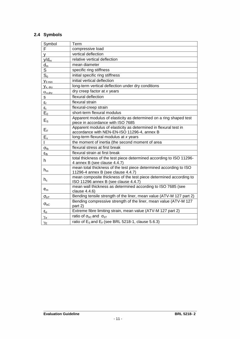
2.4 Symbols
Symbol Term
F compressive load
y vertical deflection
y/dm relative vertical deflection
dm mean diameter
S specific ring stiffness
S0 initial specific ring stiffness
y3 min initial vertical deflection
yx, dry long-term vertical deflection under dry conditions
x,dry dry creep factor at x years
s flexural deflection
εf flexural strain
εt flexural-creep strain
E0 short-term flexural modulus
ES Apparent modulus of elasticity as determined on a ring shaped test piece in accordance with ISO 7685
EF Apparent modulus of elasticity as determined in flexural test in accordance with NEN-EN-ISO 11296-4, annex B
Ex long-term flexural modulus at x years
I the moment of inertia (the second moment of area
σfb flexural stress at first break
εfb flexural strain at first break
h total thickness of the test piece determined according to ISO 11296-4 annex B (see clause 4.4.7)
hm mean total thickness of the test piece determined according to ISO 11296-4 annex B (see clause 4.4.7)
hc mean composite thickness of the test piece determined according to ISO 11296 annex B (see clause 4.4.7)
em mean wall thickness as determined according to ISO 7685 (see clause 4.4.6)
σbT Bending tensile strength of the liner, mean value (ATV-M 127 part 2)
σbC Bending compressive strength of the liner, mean value (ATV-M 127 part 2)
εp Extreme fibre limiting strain, mean value (ATV-M 127 part 2)
σ ratio of σbC and σbT
E ratio of ES and EF (see BRL 5218-1, clause 5.6.3)
Evaluation Guideline BRL 5218- 2
- 12 -
3 Procedure for obtaining a quality certificate
3.1 Assessment of approval The assessment of approval, conducted by the certification body, will be performed on basis of the product requirements and the determination methods in this evaluation guideline and contain: • (Sample) research, to determine whether the products meet the product requirements; • Assessment of the production of individual liner components; • Assessment of the quality system and the IQC scheme; • Examination for the presence and operation of other required procedures; • Assessment of the regulations of the supplier.
3.2 Certification After completion of the assessment of approval results are presented to the decision maker. The decision maker assesses the results and determines whether the certificate can be granted or that additional information and / or studies are required before a certificate can be granted.
Evaluation Guideline BRL 5218- 2
- 13 -
4 Product requirements and determination methods
4.1 General In this chapter the product requirements are laid down for cured-in-place pipes (CIPP) and their intermediates of the liner system. Also in this chapter the determination methods, to determine whether these requirements are met, are laid down. This includes requirements related to NEN-EN-ISO 11296 Part 1 and 4 and requirements of normative documents and requirements set by the Board of Experts. The requirements will be included in the technical specification of the product, which is contained in the product certificate. Following NEN-EN-ISO 11296, the distinction is made between "Manufactured" phase (M-phase) and "Installed" phase (I-phase). "M-phase" refers to a stage as manufactured, i.e. before any subsequent site processing of components associated with the cured-in-place pipe (CIPP) renovation technique. The "I-Phase" refers the stage as installed, i.e. in final configuration after any site
processing of components associated with the CIPP renovation technique.
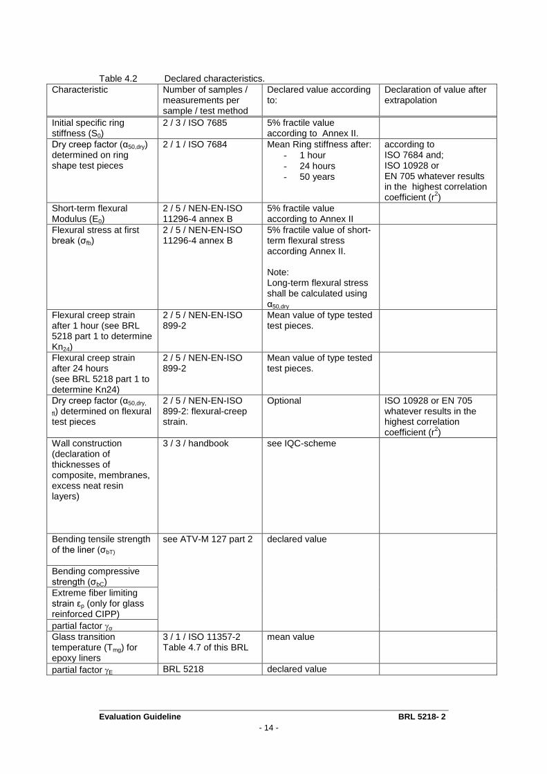
4.2 Declaration of characteristics Characteristics shall be declared by the supplier on the basis of type tests. Data from the type testing shall be provided to the certification institute to be able to control the calculated declared characteristics. In table 4.2 the required declared characteristics are listed. For type test purposes samples shall be obtained from type test groups defined by the condition in table 4.1. Table 4.1 Groups for type test purposes.
Group Limitation of groups
1 100 ≤ DN < 200
2 200 ≤ DN < 600
3 DN ≥ 600
Evaluation Guideline BRL 5218- 2
- 14 -
Table 4.2 Declared characteristics.
Characteristic Number of samples / measurements per sample / test method
Declared value according to:
Declaration of value after extrapolation
Initial specific ring stiffness (S0)
2 / 3 / ISO 7685 5% fractile value according to Annex II.
Dry creep factor (α50,dry) determined on ring shape test pieces
2 / 1 / ISO 7684 Mean Ring stiffness after:
- 1 hour
- 24 hours - 50 years
according to ISO 7684 and; ISO 10928 or EN 705 whatever results in the highest correlation coefficient (r
2)
Short-term flexural Modulus (E0)
2 / 5 / NEN-EN-ISO 11296-4 annex B
5% fractile value according to Annex II
Flexural stress at first break (σfb)
2 / 5 / NEN-EN-ISO 11296-4 annex B
5% fractile value of short-term flexural stress according Annex II. Note: Long-term flexural stress shall be calculated using α50,dry
Flexural creep strain after 1 hour (see BRL 5218 part 1 to determine Kn24)
2 / 5 / NEN-EN-ISO 899-2
Mean value of type tested test pieces.
Flexural creep strain after 24 hours (see BRL 5218 part 1 to determine Kn24)
2 / 5 / NEN-EN-ISO 899-2
Mean value of type tested test pieces.
Dry creep factor (α50,dry,
fl) determined on flexural test pieces
2 / 5 / NEN-EN-ISO 899-2: flexural-creep strain.
Optional ISO 10928 or EN 705 whatever results in the highest correlation coefficient (r
2)
Wall construction (declaration of thicknesses of composite, membranes, excess neat resin layers)
3 / 3 / handbook see IQC-scheme
Bending tensile strength of the liner (σbT)
see ATV-M 127 part 2 declared value
Bending compressive strength (σbC)
Extreme fiber limiting strain εp (only for glass reinforced CIPP)
partial factor σ
Glass transition temperature (Tmg) for epoxy liners
3 / 1 / ISO 11357-2 Table 4.7 of this BRL
mean value
partial factor E BRL 5218 declared value
Evaluation Guideline BRL 5218- 2
- 15 -
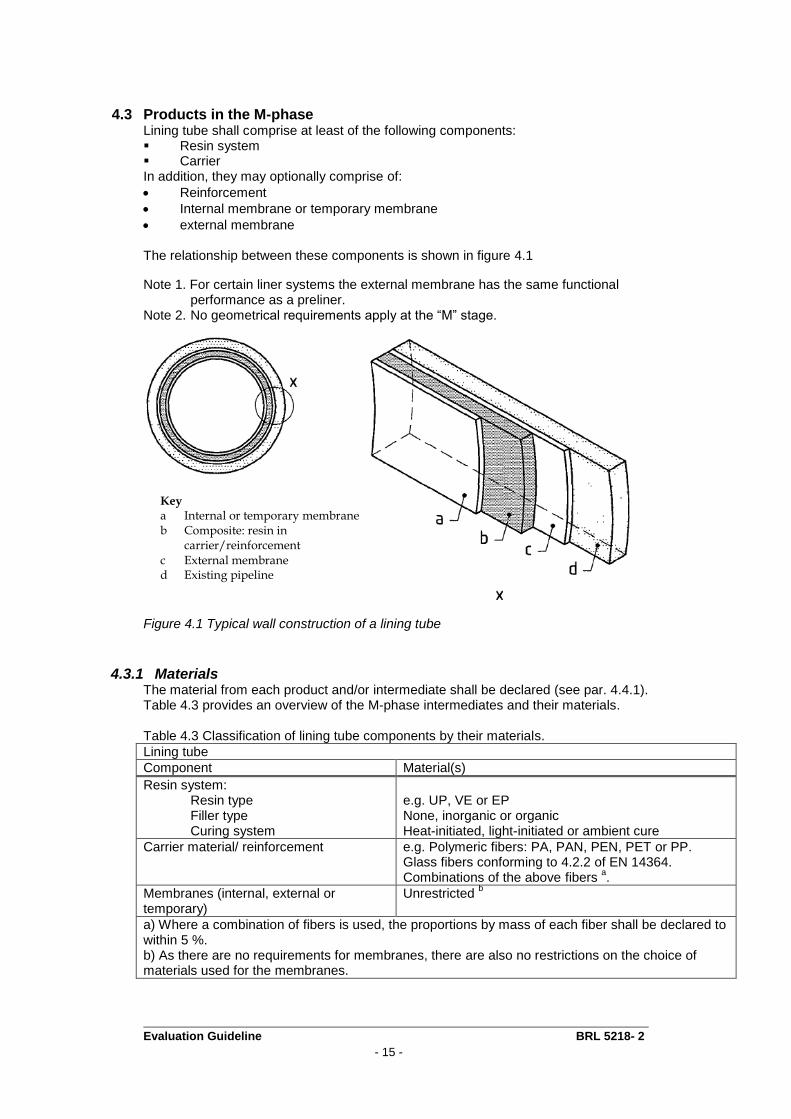
4.3 Products in the M-phase Lining tube shall comprise at least of the following components: Resin system Carrier In addition, they may optionally comprise of:
Reinforcement
Internal membrane or temporary membrane
external membrane The relationship between these components is shown in figure 4.1
Note 1. For certain liner systems the external membrane has the same functional performance as a preliner.
Note 2. No geometrical requirements apply at the “M” stage.
Figure 4.1 Typical wall construction of a lining tube
4.3.1 Materials The material from each product and/or intermediate shall be declared (see par. 4.4.1). Table 4.3 provides an overview of the M-phase intermediates and their materials. Table 4.3 Classification of lining tube components by their materials.
Lining tube
Component Material(s)
Resin system: Resin type Filler type Curing system
e.g. UP, VE or EP None, inorganic or organic Heat-initiated, light-initiated or ambient cure
Carrier material/ reinforcement e.g. Polymeric fibers: PA, PAN, PEN, PET or PP. Glass fibers conforming to 4.2.2 of EN 14364. Combinations of the above fibers
a.
Membranes (internal, external or temporary)
Unrestricted b
a) Where a combination of fibers is used, the proportions by mass of each fiber shall be declared to within 5 %. b) As there are no requirements for membranes, there are also no restrictions on the choice of materials used for the membranes.
Key a Internal or temporary membrane b Composite: resin in
carrier/reinforcement c External membrane d Existing pipeline
Evaluation Guideline BRL 5218- 2
- 16 -
Note: For example (e.g) is used here to prevent exclusion of innovative products. Suppliers of innovative products shall demonstrate that the products fulfil the requirements of BRL 5218 parts 1, -2 and -3.
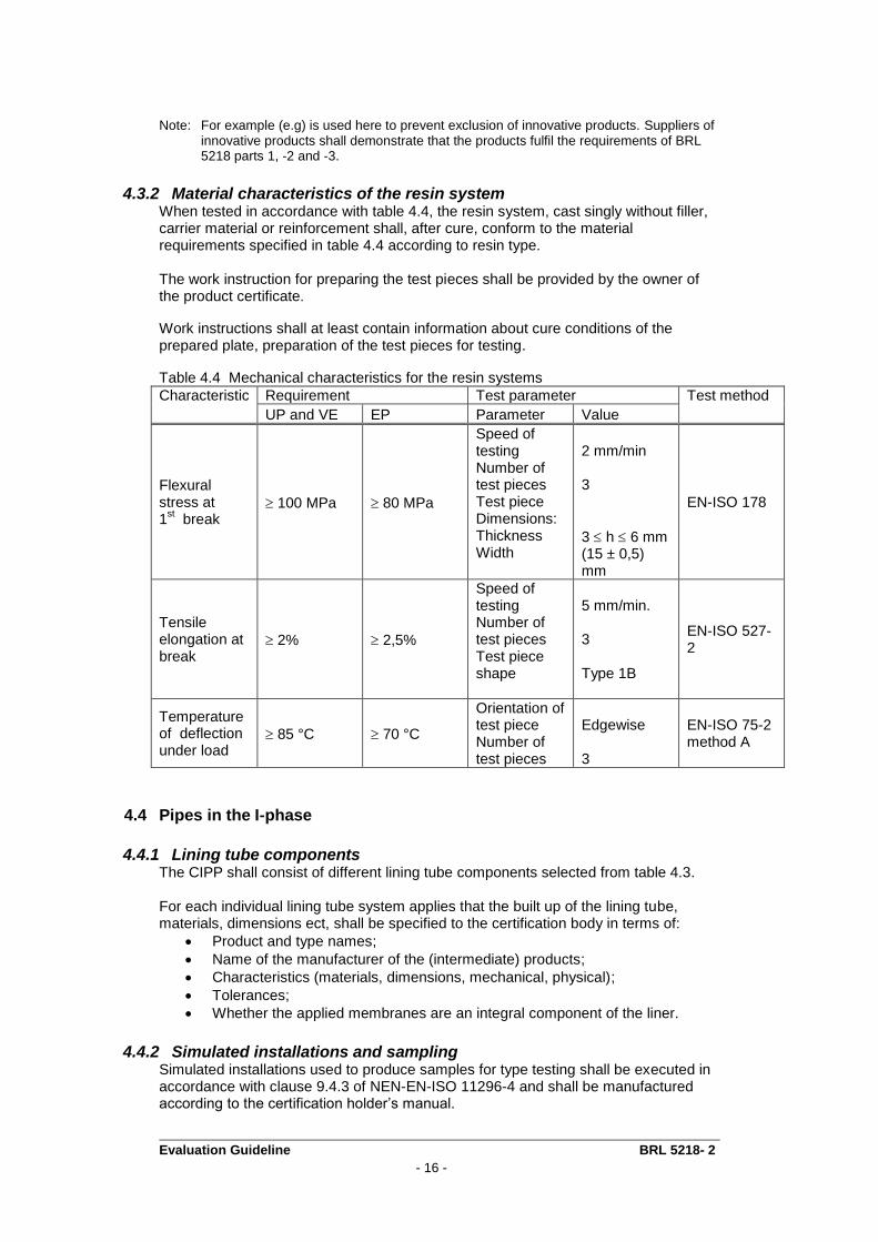
4.3.2 Material characteristics of the resin system When tested in accordance with table 4.4, the resin system, cast singly without filler, carrier material or reinforcement shall, after cure, conform to the material requirements specified in table 4.4 according to resin type. The work instruction for preparing the test pieces shall be provided by the owner of the product certificate.
Work instructions shall at least contain information about cure conditions of the prepared plate, preparation of the test pieces for testing.
Table 4.4 Mechanical characteristics for the resin systems
Characteristic Requirement Test parameter Test method
UP and VE EP Parameter Value
Flexural stress at 1
st break
100 MPa 80 MPa
Speed of testing Number of test pieces Test piece Dimensions: Thickness Width
2 mm/min 3
3 h 6 mm (15 ± 0,5) mm
EN-ISO 178
Tensile elongation at break
2% 2,5%
Speed of testing Number of test pieces Test piece shape
5 mm/min. 3 Type 1B
EN-ISO 527-2
Temperature of deflection under load
85 °C 70 °C
Orientation of test piece Number of test pieces
Edgewise 3
EN-ISO 75-2 method A
4.4 Pipes in the I-phase
4.4.1 Lining tube components The CIPP shall consist of different lining tube components selected from table 4.3. For each individual lining tube system applies that the built up of the lining tube, materials, dimensions ect, shall be specified to the certification body in terms of:
Product and type names;
Name of the manufacturer of the (intermediate) products;
Characteristics (materials, dimensions, mechanical, physical);
Tolerances;
Whether the applied membranes are an integral component of the liner.
4.4.2 Simulated installations and sampling Simulated installations used to produce samples for type testing shall be executed in accordance with clause 9.4.3 of NEN-EN-ISO 11296-4 and shall be manufactured according to the certification holder’s manual.
Evaluation Guideline BRL 5218- 2
- 17 -
4.4.3 Conditioning of samples prior to testing Unless otherwise specified by the manufacturer, the test piece shall be at least 24 hours old. Store the test pieces at least 24 hours at the test temperature prior to testing
Note: The age (period after curing) and storage conditions (temperature, relative
humidity) of the test pieces can affect the results of the tests.
4.4.4 Mechanical characteristics In table 4.5 the requirements regarding the mechanical properties are listed.

Evaluation Guideline BRL 5218- 2
- 18 -
Table 4.5 Mechanical characteristics of cured-in-place-pipes
Characteristic Requirement Test parameter Test method Parameter Value
Initial specific ring stiffness (S0)
Declared value, but not less than the greater of: 250 N/m
2 or
(125/50,dry) N/m2
Number of test pieces Test piece length for:
dm 300mm dm > 300mm Temperature Relative deflection (method B)
2 dm mm ± 5% 300 mm ± 5% (23 ± 2) °C (3 ± 0,5) %
ISO 7685, method A or B
Dry creep factor (α50, dry)
Declared value, but not less than 0,2
Method 1 (ring test) Number of test pieces Test piece length for:
dm 300mm dm > 300mm Test period time to which values are to be extrapolated Temperature Relative humidity Relative deflection
2 dm mm ± 5% 300 mm ± 5% 10000 hours 50 years (23 ± 2) °C (50 ± 5) % 1,5% < y/dm <2%
ISO 7684
Method 2 (3-point flexural test) Number of test pieces Test period time to which values are to be extrapolated Temperature Relative humidity Initial flexural strain εf
5 10000 h 50 years (23 ± 2) °C (50 ± 5) % εfi = (0,2 ± 0,01) %
ISO 11296-4, annex D, ISO 178
Short-term flexural modulus (E0)
Declared value, but not less than 1500 MPa
Number of test pieces Test speed Temperature
5 10 mm/min (23 ± 2) °C
ISO 178 as modified by annex B of ISO 11296-4
Flexural stress at first
break (fb)
Declared value, but not less than 25 MPa
Flexural strain at first break (εfb)
Declared value, but not less than 0,75%
For the purpose of three-point flexural testing the orientation of the samples shall be as follows. For CIPP products in which the mean hoop and longitudinal flexural properties can be shown by tests on flat plates to differ by no more than ± 10 %, either longitudinal or hoop samples may be used. The sample orientation chosen for type testing shall, however, become the sample orientation requirement for all further flexural testing. For CIPP products of anisotropic wall construction, hoop samples only shall be used.
Evaluation Guideline BRL 5218- 2
- 19 -
In all cases, test pieces shall be placed in the testing machine in such a manner that the inside surface of the CIPP is in contact with the supports and therefore subjected to tension. Data shall be analyzed for regression using method based on least squares analyses in accordance with ISO 10928.
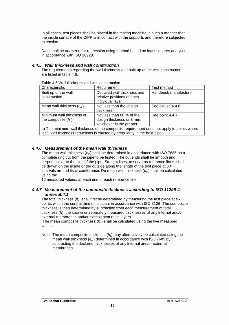
4.4.5 Wall thickness and wall construction The requirements regarding the wall thickness and built up of the wall construction are listed in table 4.6.
Table 4.6 Wall thickness and wall construction
Characteristic Requirement Test method
Built up of the wall construction
Declared wall thickness and relative positions of each individual layer
Handbook manufacturer
Mean wall thickness (em) Not less than the design thickness
See clause 4.4.6
Minimum wall thickness of the composite (hc)
Not less than 80 % of the design thickness or 3 mm, whichever is the greater
See point 4.4.7
a) The minimum wall thickness of the composite requirement does not apply to points where local wall thickness reductions is caused by irregularity in the host pipe.
4.4.6 Measurement of the mean wall thickness The mean wall thickness (em) shall be determined in accordance with ISO 7685 on a complete ring cut from the pipe to be tested. The cut ends shall be smooth and perpendicular to the axis of the pipe. Straight lines, to serve as reference lines, shall be drawn on the inside or the outside along the length of the test piece at 60° intervals around its circumference. De mean wall thickness (em) shall be calculated using the 12 measured values, at each end of each reference line.
4.4.7 Measurement of the composite thickness according to ISO 11296-4, annex B.4.1
The total thickness (h), shall first be determined by measuring the test piece at six points within the central third of its span, in accordance with ISO 3126. The composite thickness is then determined by subtracting from each measurement of total thickness (h), the known or separately measured thicknesses of any internal and/or external membranes and/or excess neat resin layers. The mean composite thickness (hc) shall be calculated using the five measured values. Note: The mean composite thickness (hc) may alternatively be calculated using the
mean wall thickness (em) determined in accordance with ISO 7685 by subtracting the declared thicknesses of any internal and/or external membranes.
Evaluation Guideline BRL 5218- 2
- 20 -
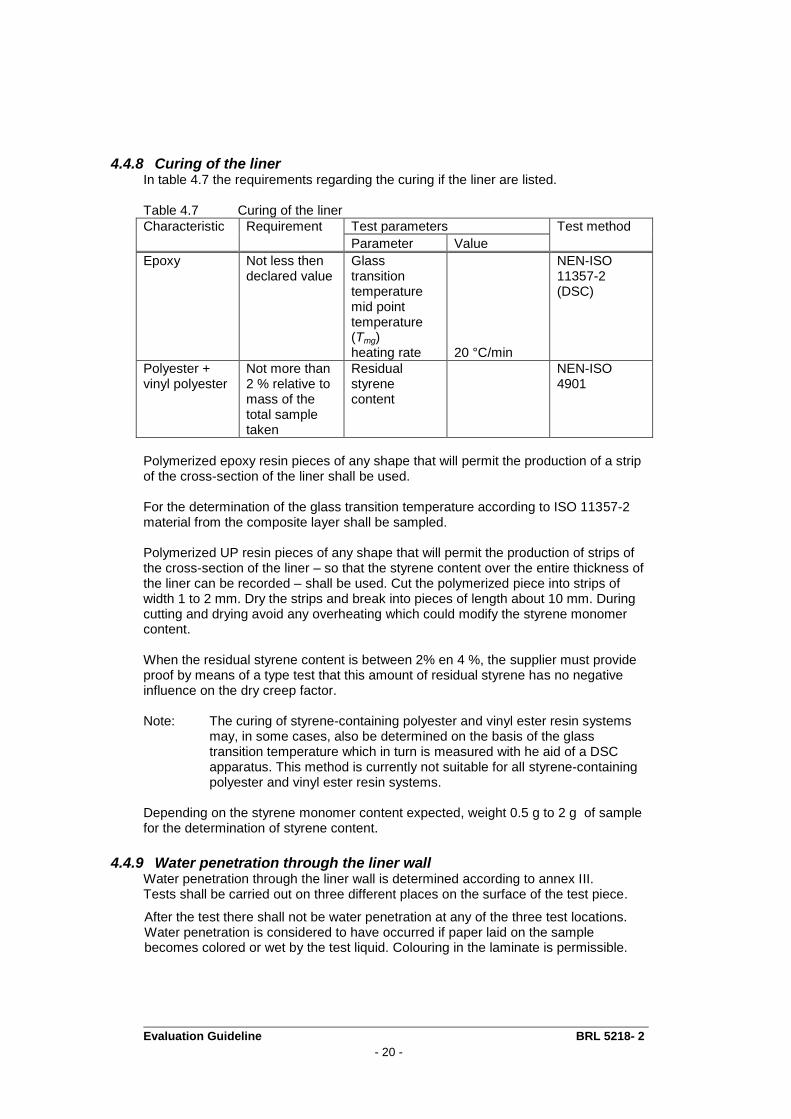
4.4.8 Curing of the liner In table 4.7 the requirements regarding the curing if the liner are listed. Table 4.7 Curing of the liner
Characteristic Requirement Test parameters Test method
Parameter Value
Epoxy
Not less then declared value
Glass transition temperature mid point temperature (Tmg) heating rate
20 °C/min
NEN-ISO 11357-2 (DSC)
Polyester + vinyl polyester
Not more than 2 % relative to mass of the total sample taken
Residual styrene content
NEN-ISO 4901
Polymerized epoxy resin pieces of any shape that will permit the production of a strip of the cross-section of the liner shall be used. For the determination of the glass transition temperature according to ISO 11357-2 material from the composite layer shall be sampled. Polymerized UP resin pieces of any shape that will permit the production of strips of the cross-section of the liner – so that the styrene content over the entire thickness of the liner can be recorded – shall be used. Cut the polymerized piece into strips of width 1 to 2 mm. Dry the strips and break into pieces of length about 10 mm. During cutting and drying avoid any overheating which could modify the styrene monomer content. When the residual styrene content is between 2% en 4 %, the supplier must provide proof by means of a type test that this amount of residual styrene has no negative influence on the dry creep factor. Note: The curing of styrene-containing polyester and vinyl ester resin systems
may, in some cases, also be determined on the basis of the glass transition temperature which in turn is measured with he aid of a DSC apparatus. This method is currently not suitable for all styrene-containing polyester and vinyl ester resin systems.
Depending on the styrene monomer content expected, weight 0.5 g to 2 g of sample for the determination of styrene content.
4.4.9 Water penetration through the liner wall Water penetration through the liner wall is determined according to annex III. Tests shall be carried out on three different places on the surface of the test piece.
After the test there shall not be water penetration at any of the three test locations. Water penetration is considered to have occurred if paper laid on the sample becomes colored or wet by the test liquid. Colouring in the laminate is permissible.
Evaluation Guideline BRL 5218- 2
- 21 -
4.4.10 Resistance to high pressure clean jetting The liner shall be resistant to high pressure clean jetting according to DIN 19523.
4.4.11 Resistance to abrassion The resistance to abrasion is determined according to NPR-CEN/TR 15729. One sample shall be tested. The length of the test piece is 1000 ± 10 mm. The changes to the inner surface of the test piece shall be determined after 200.000 number of transverses with an accuracy of ± 0,02 mm or better. Determine the maximum and mean abrasion, and report any type of damage: pitting, cracks, delamination etc. at the number of transverses reached.
4.4.12 Resistance to negative pressure When the lining tube contains an internal (not temporary) foil or membrane, the resistance to negative pressure shall be tested by means of a type test. For the test, a flat test piece is required with a length and width of approximately 300 mm. A vacuum device with a nominal diameter of approximately 12 cm is placed on the internal foil and hereafter a negative pressure of 0,8 bar is applied for a period of 1000 hours. The test shall be carried out at a temperature of (23 ± 2) °C. After testing, the test piece may not show any signs of delamination (between the internal foil and the composite layer).
4.5 Installation and user instructions The manufacturer shall make appropriate installation and user instructions available.
4.6 Certification mark The following marks and indications must be applied right and clear on each product: - Manufacturer name or trademark; - Date of production or encoding; - Type designation; - the following KOMO ® logo;
certificate number.
Evaluation Guideline BRL 5218- 2
- 22 -
5 Quality system requirements
5.1 General This chapter contains the requirements that have to be fulfilled by the manufacturer’s quality system.
5.2 Manager of the quality system Within the manufacturer’s organisational structure an employee must be appointed who is in charge of managing the quality system.
5.3 Internal quality control/quality plan As part of the quality system the manufacturer must implement an internal quality control schedule (IQC-scheme). In this IQC-scheme the following must be demonstrably recorded:
which aspects are inspected by the manufacturer;
according to which methods these inspections are carried out;
how often these inspections are carried out;
how the inspection results are registered and stored. This IQC-schedule shall be in the format as shown in the annex I. The schedule must be detailed in such a way that it provides the certification body sufficient confidence that requirements will be continuously fulfilled. At the time of the assessment of approval this schedule must function a minimum of three months.
5.4 Procedures and work instructions The manufacturer must be able to submit, procedures for:
the handling of non-conforming products;
corrective actions in case non-conformities are found;
the handling of complaints regarding the products and / or services supplied;
the work instructions and inspection sheets in use;
instructions for packaging and closing off of products during storage and transport.
Evaluation Guideline BRL 5218- 2
- 23 -
6 Summary of tests and inspections
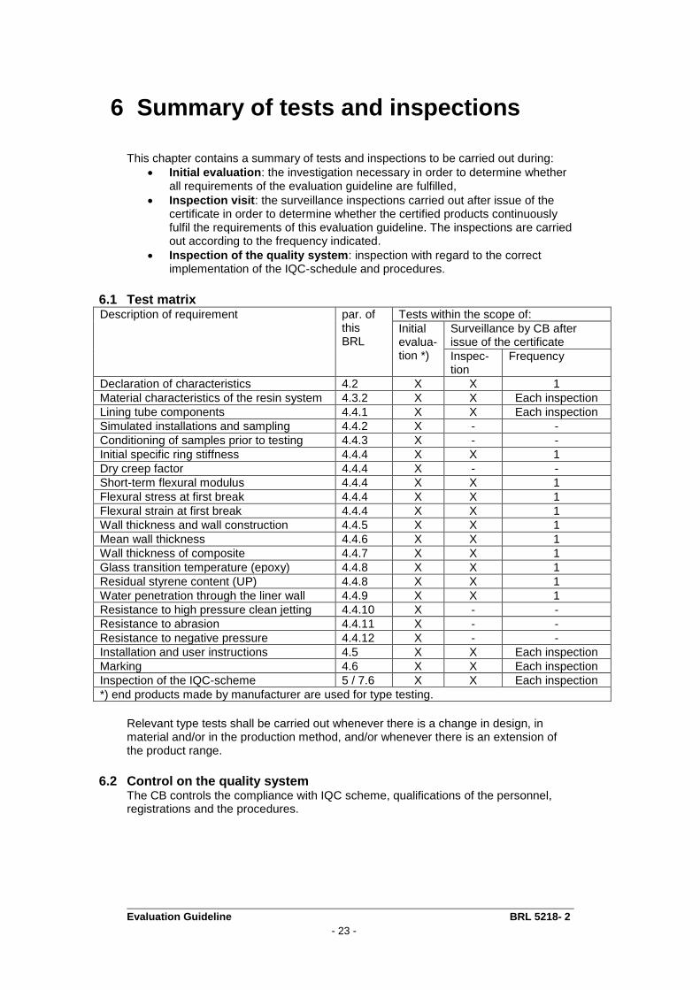
This chapter contains a summary of tests and inspections to be carried out during:
Initial evaluation: the investigation necessary in order to determine whether all requirements of the evaluation guideline are fulfilled,
Inspection visit: the surveillance inspections carried out after issue of the certificate in order to determine whether the certified products continuously fulfil the requirements of this evaluation guideline. The inspections are carried out according to the frequency indicated.
Inspection of the quality system: inspection with regard to the correct implementation of the IQC-schedule and procedures.
6.1 Test matrix Description of requirement par. of
this BRL
Tests within the scope of:
Initial evalua-tion *)
Surveillance by CB after issue of the certificate
Inspec-tion
Frequency
Declaration of characteristics 4.2 X X 1
Material characteristics of the resin system 4.3.2 X X Each inspection
Lining tube components 4.4.1 X X Each inspection
Simulated installations and sampling 4.4.2 X - -
Conditioning of samples prior to testing 4.4.3 X - -
Initial specific ring stiffness 4.4.4 X X 1
Dry creep factor 4.4.4 X - -
Short-term flexural modulus 4.4.4 X X 1
Flexural stress at first break 4.4.4 X X 1
Flexural strain at first break 4.4.4 X X 1
Wall thickness and wall construction 4.4.5 X X 1
Mean wall thickness 4.4.6 X X 1
Wall thickness of composite 4.4.7 X X 1
Glass transition temperature (epoxy) 4.4.8 X X 1
Residual styrene content (UP) 4.4.8 X X 1
Water penetration through the liner wall 4.4.9 X X 1
Resistance to high pressure clean jetting 4.4.10 X - -
Resistance to abrasion 4.4.11 X - -
Resistance to negative pressure 4.4.12 X - -
Installation and user instructions 4.5 X X Each inspection
Marking 4.6 X X Each inspection
Inspection of the IQC-scheme 5 / 7.6 X X Each inspection
*) end products made by manufacturer are used for type testing.
Relevant type tests shall be carried out whenever there is a change in design, in material and/or in the production method, and/or whenever there is an extension of the product range.
6.2 Control on the quality system The CB controls the compliance with IQC scheme, qualifications of the personnel, registrations and the procedures.
Evaluation Guideline BRL 5218- 2
- 24 -
7 Requirements imposed on the certification body
7.1 General The certification body has to fulfil the requirements of EN 45011. Furthermore, the certification body has to be accredited for the subject of this evaluation guideline by the Dutch Accreditation Council (RvA) or by an equivalent accreditation body (an accreditation body with whom RvA has signed an agreement of mutual recognition). The certification body must have the disposal of a regulation, or an equivalent document, in which the general rules for certification are laid down. In particular these are:
The general rules for carrying out the pre-certification, to be distinguished in:
The way suppliers are informed about the handling of the application;
execution of the pre-certification;
the decision with regard to the pre-certification executed.
The general rules with regard to the execution of inspections and the inspection aspects to be employed;
The measures to be taken by the certification body in the event of nonconformities;
The rules for termination of the certificate;
The possibility of lodging appeal against decisions or measures made by the certification body.
7.2 Certification staff The staff involved in the certification is to be sub-divided into:
Certification experts/Auditors: in charge of carrying out the pre-certification tests and assessing the inspectors reports;
Inspectors: in charge of carrying out external inspections at the supplier’s works;
Decision-makers: in charge of taking decisions in connection with the pre-certification tests performed, continuing the certification in connection with the inspections performed and taking decisions on the need of corrective actions.
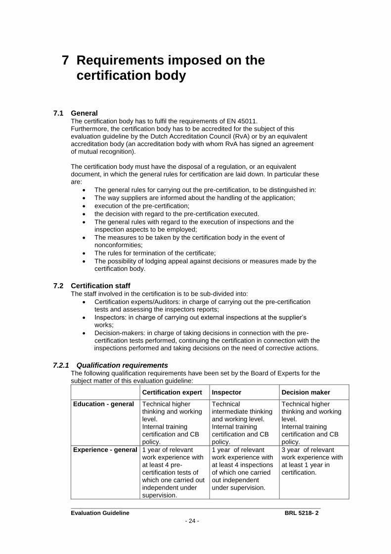
7.2.1 Qualification requirements The following qualification requirements have been set by the Board of Experts for the subject matter of this evaluation guideline:
Certification expert Inspector Decision maker
Education - general Technical higher thinking and working level. Internal training certification and CB policy.
Technical intermediate thinking and working level. Internal training certification and CB policy.
Technical higher thinking and working level. Internal training certification and CB policy.
Experience - general 1 year of relevant work experience with at least 4 pre-certification tests of which one carried out independent under supervision.
1 year of relevant work experience with at least 4 inspections of which one carried out independent under supervision.
3 year of relevant work experience with at least 1 year in certification.
Evaluation Guideline BRL 5218- 2
- 25 -
7.2.2 Qualification The qualification of the Certification staff shall be demonstrated by means of assessing the education and experience to the requirements mentioned before. In case staff is to be qualified on the basis of deflecting criteria, written records shall be kept. The authority to qualify staff is dedicated to:
decision makers: qualification of certification experts and inspectors;
Management of the CB: qualification of decision makers.
7.3 Report Pre-certification tests The CB records the results of the pre-certification tests in a report. This report shall comply with the following requirements:
completeness: the reports verdicts about all requirements included in the evaluation guideline;
traceability: the findings on which the verdicts have been based shall be recorded traceable;
basis for decision: the decision maker shall be able to base his decision on the findings included in the report.
7.4 Decision for granting the certificate The decision for granting the certificate shall be made by a qualified decision maker which has not been involved in the pre-certification tests. The decision shall be recorded traceable.
7.5 Nature and frequency of external inspections The CB shall carry out audits at the supplier at regular intervals to check whether the supplier complies with his obligations. About the frequency of inspections the Board of Experts decides. At the time this evaluation guideline took effect, the frequency was set at number of two inspection visits per year. In case the supplier is ISO 9001 certified for the scope and production location concerned, the frequency has been set at 1 inspection visit per year. Inspections shall at least refer to the suppliers IQC-scheme and the results obtained from inspections carried out by the supplier. The correct way of marking of certified products and complying with required procedures.
The results of each inspection shall be traceable recorded in a report.
7.6 Interpretation of requirements The Board of Experts (CvD-LSK) may record the interpretation of requirements of these evaluation guidelines in one separate interpretation document.
Evaluation Guideline BRL 5218- 2
- 26 -
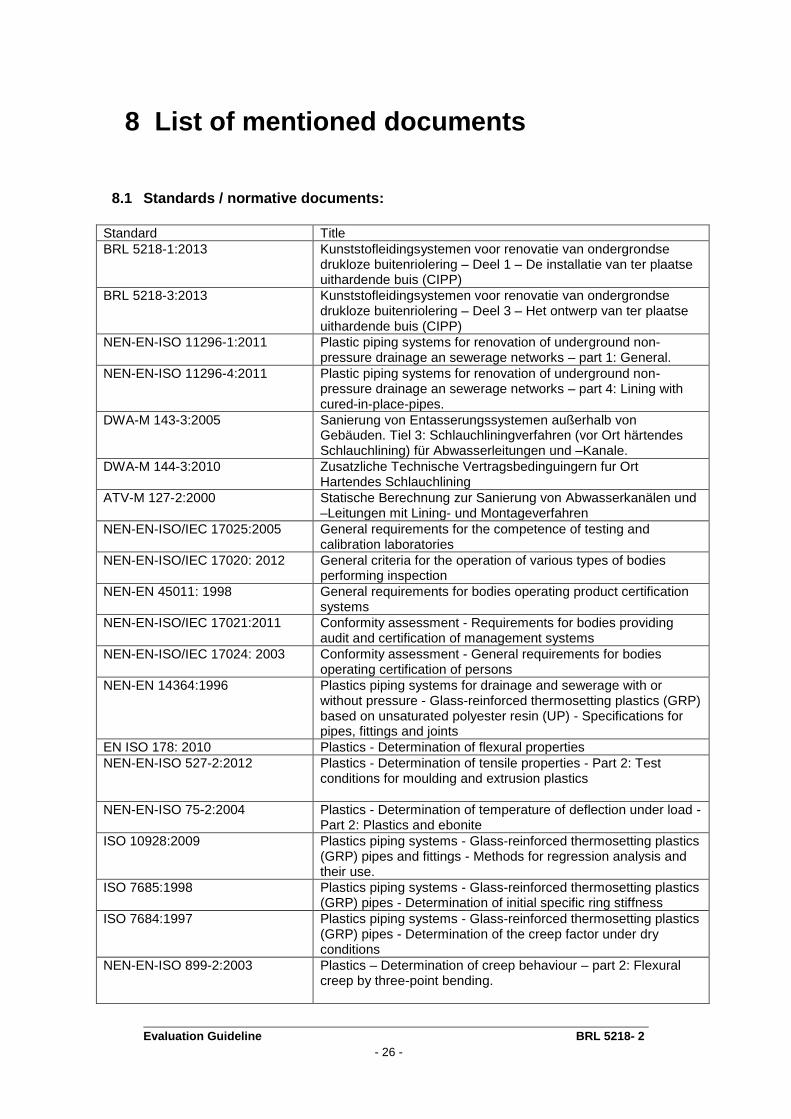
8 List of mentioned documents
8.1 Standards / normative documents:
Standard Title
BRL 5218-1:2013 Kunststofleidingsystemen voor renovatie van ondergrondse drukloze buitenriolering – Deel 1 – De installatie van ter plaatse uithardende buis (CIPP)
BRL 5218-3:2013 Kunststofleidingsystemen voor renovatie van ondergrondse drukloze buitenriolering – Deel 3 – Het ontwerp van ter plaatse uithardende buis (CIPP)
NEN-EN-ISO 11296-1:2011 Plastic piping systems for renovation of underground non-pressure drainage an sewerage networks – part 1: General.
NEN-EN-ISO 11296-4:2011 Plastic piping systems for renovation of underground non-pressure drainage an sewerage networks – part 4: Lining with cured-in-place-pipes.
DWA-M 143-3:2005 Sanierung von Entasserungssystemen außerhalb von Gebäuden. Tiel 3: Schlauchliningverfahren (vor Ort härtendes Schlauchlining) für Abwasserleitungen und –Kanale.
DWA-M 144-3:2010 Zusatzliche Technische Vertragsbedinguingern fur Ort Hartendes Schlauchlining
ATV-M 127-2:2000 Statische Berechnung zur Sanierung von Abwasserkanälen und –Leitungen mit Lining- und Montageverfahren
NEN-EN-ISO/IEC 17025:2005 General requirements for the competence of testing and calibration laboratories
NEN-EN-ISO/IEC 17020: 2012 General criteria for the operation of various types of bodies performing inspection
NEN-EN 45011: 1998 General requirements for bodies operating product certification systems
NEN-EN-ISO/IEC 17021:2011 Conformity assessment - Requirements for bodies providing audit and certification of management systems
NEN-EN-ISO/IEC 17024: 2003 Conformity assessment - General requirements for bodies operating certification of persons
NEN-EN 14364:1996 Plastics piping systems for drainage and sewerage with or without pressure - Glass-reinforced thermosetting plastics (GRP) based on unsaturated polyester resin (UP) - Specifications for pipes, fittings and joints
EN ISO 178: 2010 Plastics - Determination of flexural properties
NEN-EN-ISO 527-2:2012 Plastics - Determination of tensile properties - Part 2: Test conditions for moulding and extrusion plastics
NEN-EN-ISO 75-2:2004 Plastics - Determination of temperature of deflection under load - Part 2: Plastics and ebonite
ISO 10928:2009 Plastics piping systems - Glass-reinforced thermosetting plastics (GRP) pipes and fittings - Methods for regression analysis and their use.
ISO 7685:1998 Plastics piping systems - Glass-reinforced thermosetting plastics (GRP) pipes - Determination of initial specific ring stiffness
ISO 7684:1997 Plastics piping systems - Glass-reinforced thermosetting plastics (GRP) pipes - Determination of the creep factor under dry conditions
NEN-EN-ISO 899-2:2003 Plastics – Determination of creep behaviour – part 2: Flexural creep by three-point bending.
Evaluation Guideline BRL 5218- 2
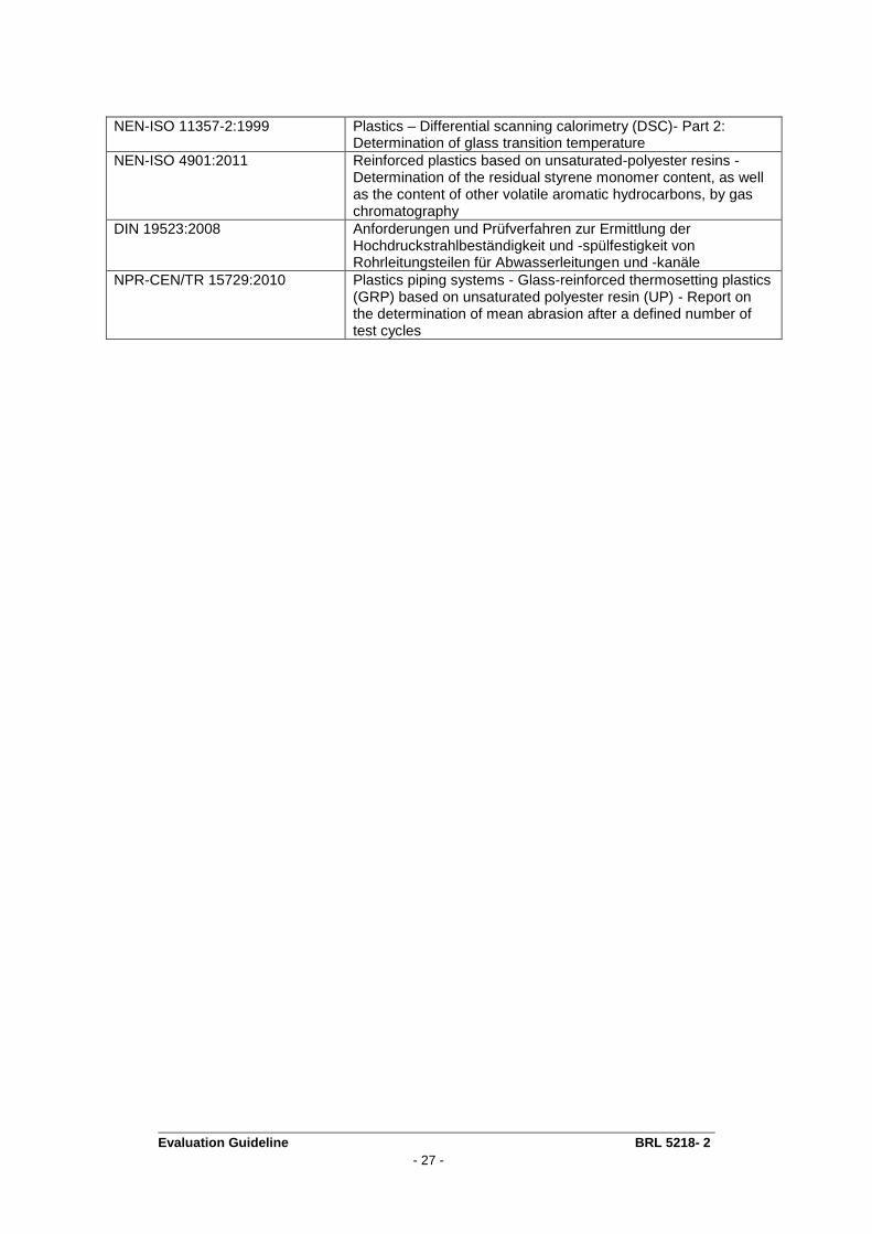
- 27 -
NEN-ISO 11357-2:1999 Plastics – Differential scanning calorimetry (DSC)- Part 2: Determination of glass transition temperature
NEN-ISO 4901:2011 Reinforced plastics based on unsaturated-polyester resins - Determination of the residual styrene monomer content, as well as the content of other volatile aromatic hydrocarbons, by gas chromatography
DIN 19523:2008 Anforderungen und Prüfverfahren zur Ermittlung der Hochdruckstrahlbeständigkeit und -spülfestigkeit von Rohrleitungsteilen für Abwasserleitungen und -kanäle
NPR-CEN/TR 15729:2010 Plastics piping systems - Glass-reinforced thermosetting plastics (GRP) based on unsaturated polyester resin (UP) - Report on the determination of mean abrasion after a defined number of test cycles
Evaluation Guideline BRL 5218- 2
- 28 -
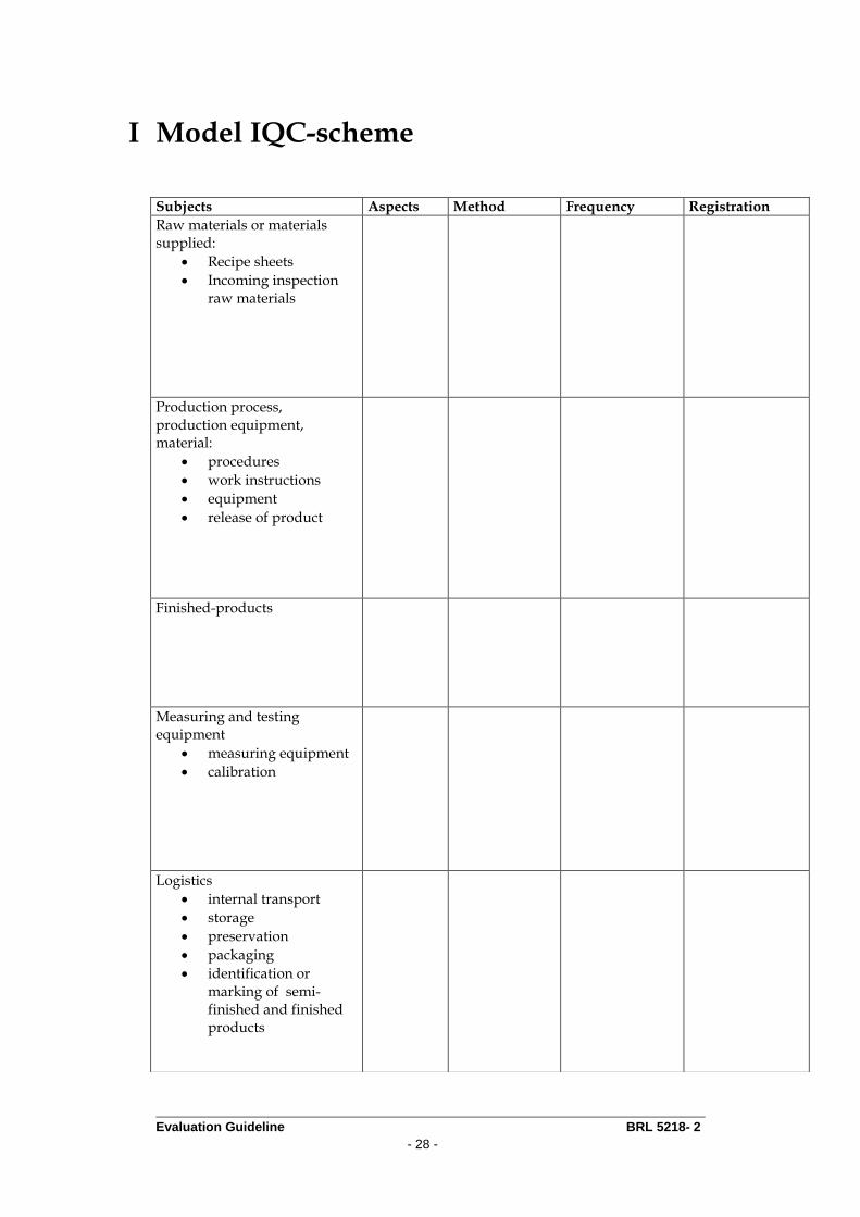
I Model IQC-scheme
Subjects Aspects Method Frequency Registration
Raw materials or materials supplied:
Recipe sheets
Incoming inspection raw materials
Production process, production equipment, material:
procedures
work instructions
equipment
release of product
Finished-products
Measuring and testing equipment
measuring equipment
calibration
Logistics
internal transport
storage
preservation
packaging
identification or marking of semi-finished and finished products
Evaluation Guideline BRL 5218- 2
- 29 -
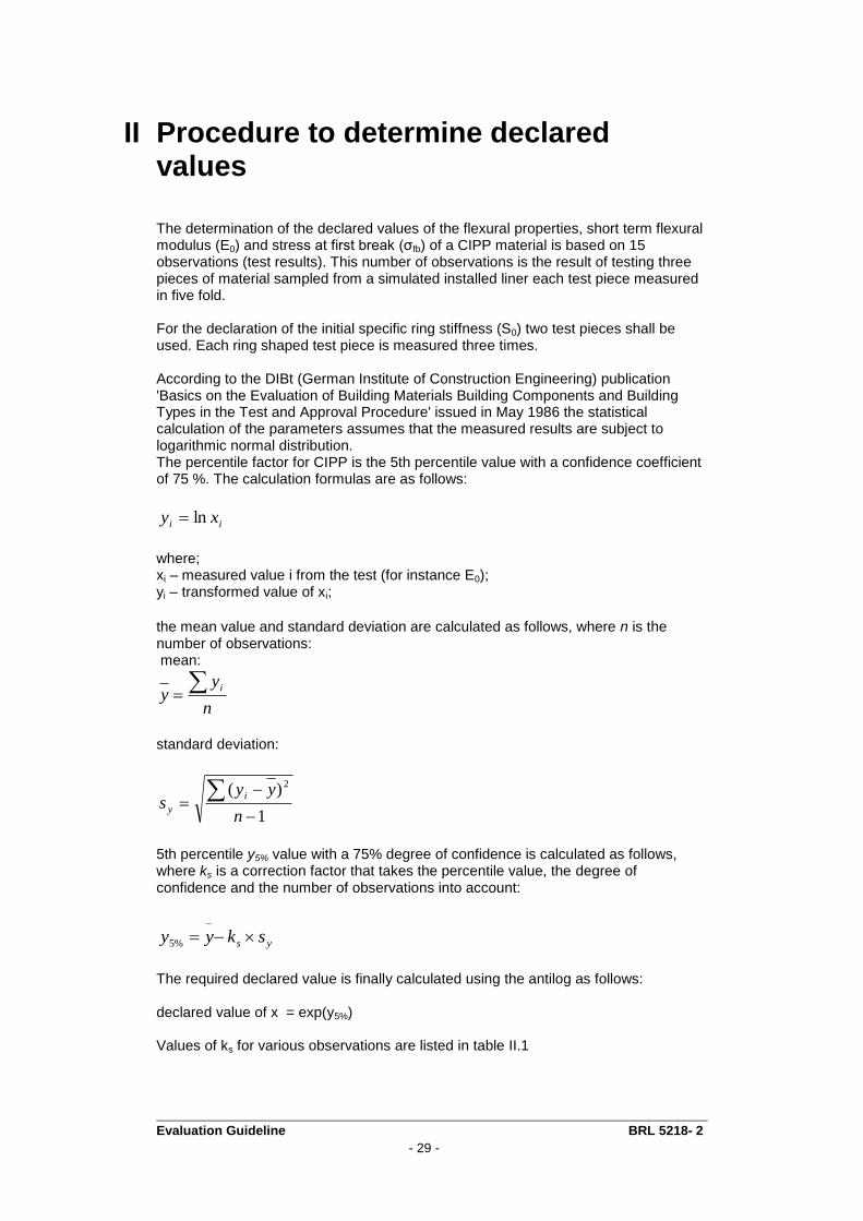
II Procedure to determine declared values
The determination of the declared values of the flexural properties, short term flexural modulus (E0) and stress at first break (σfb) of a CIPP material is based on 15 observations (test results). This number of observations is the result of testing three pieces of material sampled from a simulated installed liner each test piece measured in five fold. For the declaration of the initial specific ring stiffness (S0) two test pieces shall be used. Each ring shaped test piece is measured three times. According to the DIBt (German Institute of Construction Engineering) publication 'Basics on the Evaluation of Building Materials Building Components and Building Types in the Test and Approval Procedure' issued in May 1986 the statistical calculation of the parameters assumes that the measured results are subject to logarithmic normal distribution. The percentile factor for CIPP is the 5th percentile value with a confidence coefficient of 75 %. The calculation formulas are as follows:
ii xy ln
where; xi – measured value i from the test (for instance E0); yi – transformed value of xi;
the mean value and standard deviation are calculated as follows, where n is the number of observations: mean:
n
yy
i
standard deviation:
1
)( 2
n
yys
i
y
5th percentile y5% value with a 75% degree of confidence is calculated as follows, where ks is a correction factor that takes the percentile value, the degree of confidence and the number of observations into account:
ys skyy
%5
The required declared value is finally calculated using the antilog as follows: declared value of x = exp(y5%) Values of ks for various observations are listed in table II.1
Evaluation Guideline BRL 5218- 2
- 30 -
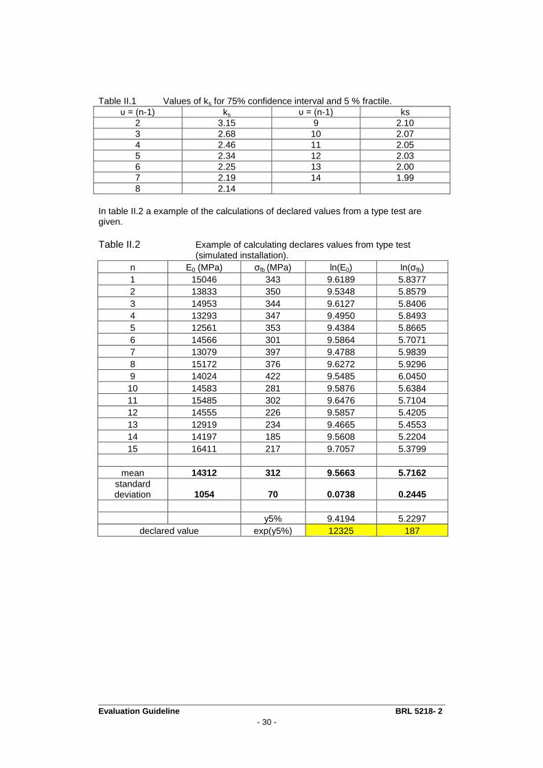
Table II.1 Values of ks for 75% confidence interval and 5 % fractile.
υ = (n-1) ks υ = (n-1) ks
2 3.15 9 2.10
3 2.68 10 2.07
4 2.46 11 2.05
5 2.34 12 2.03
6 2.25 13 2.00
7 2.19 14 1.99
8 2.14
In table II.2 a example of the calculations of declared values from a type test are given.
Table II.2 Example of calculating declares values from type test
(simulated installation).
n E0 (MPa) σfb (MPa) ln(E0) ln(σfb)
1 15046 343 9.6189 5.8377
2 13833 350 9.5348 5.8579
3 14953 344 9.6127 5.8406
4 13293 347 9.4950 5.8493
5 12561 353 9.4384 5.8665
6 14566 301 9.5864 5.7071
7 13079 397 9.4788 5.9839
8 15172 376 9.6272 5.9296
9 14024 422 9.5485 6.0450
10 14583 281 9.5876 5.6384
11 15485 302 9.6476 5.7104
12 14555 226 9.5857 5.4205
13 12919 234 9.4665 5.4553
14 14197 185 9.5608 5.2204
15 16411 217 9.7057 5.3799
mean 14312 312 9.5663 5.7162
standard deviation 1054 70 0.0738 0.2445
y5% 9.4194 5.2297
declared value exp(y5%) 12325 187
Evaluation Guideline BRL 5218- 2
- 31 -
III Water penetration through the liner wall
Principle The ability of water movement through the wall of the liner is determined by applying water on the inside of the liner wall and vacuum on the other side of the wall. After test duration of 30 minutes the other side of the sample is checked for water penetration through the wall.
Sample preparation A test piece with a length (axial direction) of at least 20 cm and a width (hoop direction) of at least 30 cm is sampled from the installed liner.
Membranes that are an integral component of the liner are not destroyed.
For membranes that are not an integral part of the liner, the following procedure is used:
If there is a membrane on the outside (between liner and the sewer pipe renovated), it will be removed without cutting into the membrane.
The thickness of the membrane on the inside is measured with a vernier capiller.
The surface is incised to a depth where all membranes are cut without damaging the laminate.
A grid of cut lines is applied to the surface. The distance between successive lines is 4 mm. A grid contains 10 x 10 lines that are perpendicular to each other.
The samples are to be stored at least 4 hours before testing at the specified test climate conditions.
Procedure The test is performed at three locations on the sample specimen at a temperature; (23 ± 5) °C. The test piece is placed on a flask which is connected to a device to create a negative pressure in the flask and in turn a pressure difference over the wall of the test piece. The negative pressure applied shall be (-0,5 bar ± 25 mbar) and on the outside of the sample. The testing surface has approximately the diameter of neck of the flask and shall be (45 ± 5) mm. The test liquid shall be applied on the inside of the sample. The negative pressure shall be applied for 30 minutes hereafter the test piece is checked for liquid penetration. Test liquid: drinking water (colored) without wetting agent.