plateflow gasketed pal te & frame heat exchanger...gasketed plate & frame heat exchanger...
TRANSCRIPT
Plateflow™ Gasketed Plate & Frame Heat Exchanger
INSTALLER: PLEASE LEAVE THIS MANUAL FOR THE OWNER’S USE.
INSTRUCTION MANUAL 104-70 REVB
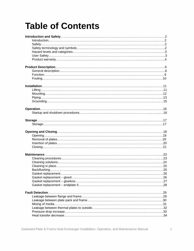
Table of Contents Introduction and Safety………………………………………………………………………………………2 Introduction...………………………………………………………………………………………..…….2 Safety………………………………………………………………………………………………..……..2 Safety terminology and symbols…………………………………………………………………….…..2 Hazard levels and categories……………………………………………………………………..……..3 User Safety………………………………………………………………………….………………….….3 Product warranty……………………………………………………………………………..…………...4 Product Description…………………………………………………………………………………………..6 General description…………………………………………………………………………………..…...6 Function……………………………………………………………………………………………………9 Fouling……………………………………………………………………………………………………10 Installation………………………………………………………………………………………….…………11 Lifting………………………………………………………………………………………...……………11 Mounting……………………………………………………………………………………….…………12 Piping………………………………………………………………………………………….….……....13 Grounding………………………………………………………………………………………...………15 Operation…………………………………………………………………………………………...…………16 Startup and shutdown procedures…………………………………………………………...…..........16 Storage……………………………………………………………………………………………..………….17 Storage……………………………………………………………………………………..…………….17 Opening and Closing………………………………………………………………………………..………18 Opening………………………………………………………………………………………..…………18 Removal of plates……………………………………………………………………………….………20 Insertion of plates…………………………………………………………….………………….………20 Closing……………………………………………………………………………………………………21 Maintenance…………………………………………………………………………………….…………….23 Cleaning procedures……………………………………………………………………………….……23 Cleaning solutions……………………………………………………………………………….………24 Cleaning in place…………………………………………………………………………………..…….25 Backflushing…………………………………………………………………………………...…………25 Gasket replacement………………………………………………………………………………..……26 Gasket replacement – glued……………………………………………………………………………26 Gasket replacement – glueless………………………………………………………………………...27 Gasket replacement – endplate II……………………………………………………………………...28 Fault Detection…………………………………………………………………………………….…………29 Leakage between flange and frame……………………………………………………………….…..29 Leakage between plate pack and frame……………………………...……………………………....30 Mixing of media………………………………………………………………………………...………..31 Leakage between thermal plates to outside……………………………………………………….….32 Pressure drop increase…………………………………………………………………..……………..33 Heat transfer decrease…………………………………………………………………...……………..34
Gasketed Plate & Frame Heat Exchanger Installation, Operation, and Maintenance Manual 1
Introduction and Safety
The purpose of this manual is to provide necessary information for: -Installation -Operation -Maintenance
CAUTION: Read this manual carefully before installing and using the product. Improper use of the product can cause personal injury and damages to property and may void the warranty.
NOTICE: Save this manual for future reference, and keep it readily available at the location of the unit.
WARNING: -The operator must be aware of safety precautions to prevent physical injury. -Operating, installing, or maintaining the unit in any way that is not covered in this manual could cause death, serious injury, or damage to the equipment. This includes any modification to the equipment or use of parts not provided by Xylem. If there is a question regarding the intended use of the equipment, please contact a Xylem representative before proceeding. -Do not change the service application without the approval of an authorized Xylem representative.
CAUTION: You must observe the instructions contained in this manual. Failure to do so could result in physical injury, damage, or delays.
It is extremely important that you read, understand, and follow the safety messages and regulations carefully before handling the product. They are published to help prevent these hazards: -Personal accidents and health problems -Damage to the product -Product malfunction
INTRODUCTION
Terminology and symbols
SAFETY
2 Gasketed Plate & Frame Heat Exchanger Installation, Operation, and Maintenance Manual
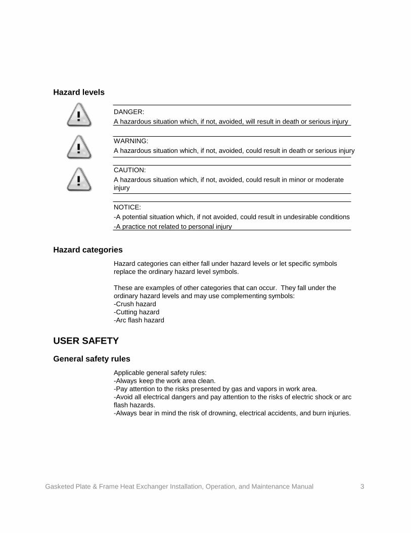
DANGER: A hazardous situation which, if not, avoided, will result in death or serious injury WARNING: A hazardous situation which, if not, avoided, could result in death or serious injury CAUTION: A hazardous situation which, if not, avoided, could result in minor or moderate injury NOTICE: -A potential situation which, if not avoided, could result in undesirable conditions -A practice not related to personal injury
Hazard categories can either fall under hazard levels or let specific symbols replace the ordinary hazard level symbols. These are examples of other categories that can occur. They fall under the ordinary hazard levels and may use complementing symbols: -Crush hazard -Cutting hazard -Arc flash hazard
Applicable general safety rules: -Always keep the work area clean. -Pay attention to the risks presented by gas and vapors in work area. -Avoid all electrical dangers and pay attention to the risks of electric shock or arc flash hazards. -Always bear in mind the risk of drowning, electrical accidents, and burn injuries.
Hazard levels
USER SAFETY
Hazard categories
General safety rules
3 Gasketed Plate & Frame Heat Exchanger Installation, Operation, and Maintenance Manual
Use safety equipment according to the company regulations. Use this safety equipment within the work area: -Hard hat -Safety goggles, preferably with side shields -Protective shoes -Protective gloves -Gas mask -Hearing protection -First-aid kit -Safety devices NOTICE: Never operate a unit unless safety devices are installed. Also see specific information about safety devices in other chapters of this manual.
Safety equipment
Xylem undertakes to remedy defects in products from Xylem under these conditions: -The faults are due to defects in design, materials, or workmanship. -The faults are reported to a local sales and service representative within the warranty period. -The product is used only under the conditions that are described in this manual. -All service and repair work that is done by Xylem authorized personnel. -Genuine Xylem parts are used.
PRODUCT WARRANTY Coverage
Limitations
Warranty does not cover defects caused by: -Deficient maintenance -Improper installation -Modifications or changes to the product and installation that are made without consulting a Xylem authorized representative -Incorrectly executed repair work -Normal wear and tear Xylem assumes no liability for the following situations: -Bodily injury -Material damages -Economic losses
4 Gasketed Plate & Frame Heat Exchanger Installation, Operation, and Maintenance Manual

Warranty claim
Xylem products are high quality products with expected reliable operation and long life. However, should the need for a warranty claim arise, contact your local sales representative or the manufacturer.
5 Gasketed Plate & Frame Heat Exchanger Installation, Operation, and Maintenance Manual
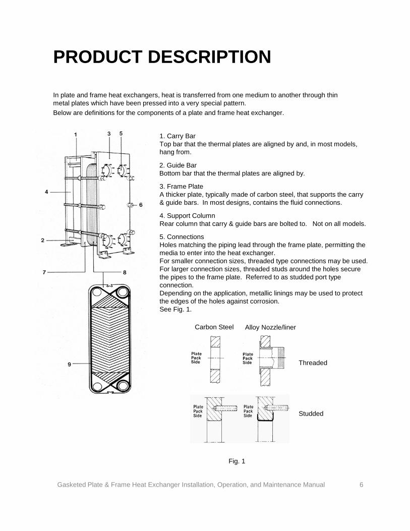
In plate and frame heat exchangers, heat is transferred from one medium to another through thin metal plates which have been pressed into a very special pattern. Below are definitions for the components of a plate and frame heat exchanger.
PRODUCT DESCRIPTION
1. Carry Bar Top bar that the thermal plates are aligned by and, in most models, hang from.
2. Guide Bar Bottom bar that the thermal plates are aligned by.
3. Frame Plate A thicker plate, typically made of carbon steel, that supports the carry & guide bars. In most designs, contains the fluid connections.
4. Support Column Rear column that carry & guide bars are bolted to. Not on all models.
5. Connections Holes matching the piping lead through the frame plate, permitting the media to enter into the heat exchanger. For smaller connection sizes, threaded type connections may be used. For larger connection sizes, threaded studs around the holes secure the pipes to the frame plate. Referred to as studded port type connection. Depending on the application, metallic linings may be used to protect the edges of the holes against corrosion. See Fig. 1.
Carbon Steel Alloy Nozzle/liner
Threaded
Studded
Fig. 1
Gasketed Plate & Frame Heat Exchanger Installation, Operation, and Maintenance Manual 6
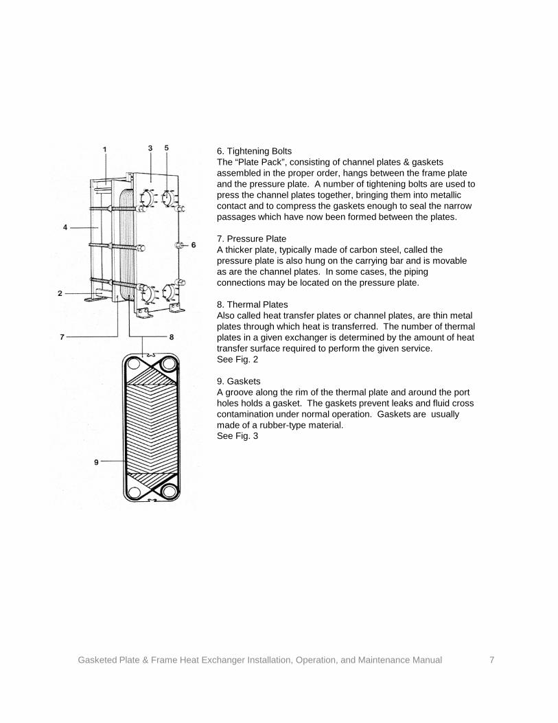
6. Tightening Bolts The “Plate Pack”, consisting of channel plates & gaskets assembled in the proper order, hangs between the frame plate and the pressure plate. A number of tightening bolts are used to press the channel plates together, bringing them into metallic contact and to compress the gaskets enough to seal the narrow passages which have now been formed between the plates. 7. Pressure Plate A thicker plate, typically made of carbon steel, called the pressure plate is also hung on the carrying bar and is movable as are the channel plates. In some cases, the piping connections may be located on the pressure plate. 8. Thermal Plates Also called heat transfer plates or channel plates, are thin metal plates through which heat is transferred. The number of thermal plates in a given exchanger is determined by the amount of heat transfer surface required to perform the given service. See Fig. 2 9. Gaskets A groove along the rim of the thermal plate and around the port holes holds a gasket. The gaskets prevent leaks and fluid cross contamination under normal operation. Gaskets are usually made of a rubber-type material. See Fig. 3
Gasketed Plate & Frame Heat Exchanger Installation, Operation, and Maintenance Manual 7
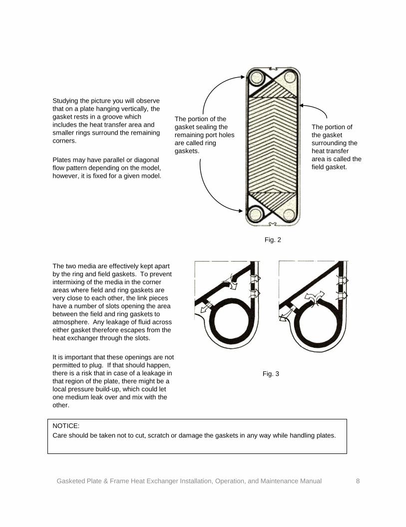
Studying the picture you will observe that on a plate hanging vertically, the gasket rests in a groove which includes the heat transfer area and smaller rings surround the remaining corners. Plates may have parallel or diagonal flow pattern depending on the model, however, it is fixed for a given model.
The portion of the gasket sealing the remaining port holes are called ring gaskets.
The portion of the gasket surrounding the heat transfer area is called the field gasket.
The two media are effectively kept apart by the ring and field gaskets. To prevent intermixing of the media in the corner areas where field and ring gaskets are very close to each other, the link pieces have a number of slots opening the area between the field and ring gaskets to atmosphere. Any leakage of fluid across either gasket therefore escapes from the heat exchanger through the slots. It is important that these openings are not permitted to plug. If that should happen, there is a risk that in case of a leakage in that region of the plate, there might be a local pressure build-up, which could let one medium leak over and mix with the other.
Fig. 2
Fig. 3
NOTICE: Care should be taken not to cut, scratch or damage the gaskets in any way while handling plates.
Gasketed Plate & Frame Heat Exchanger Installation, Operation, and Maintenance Manual 8
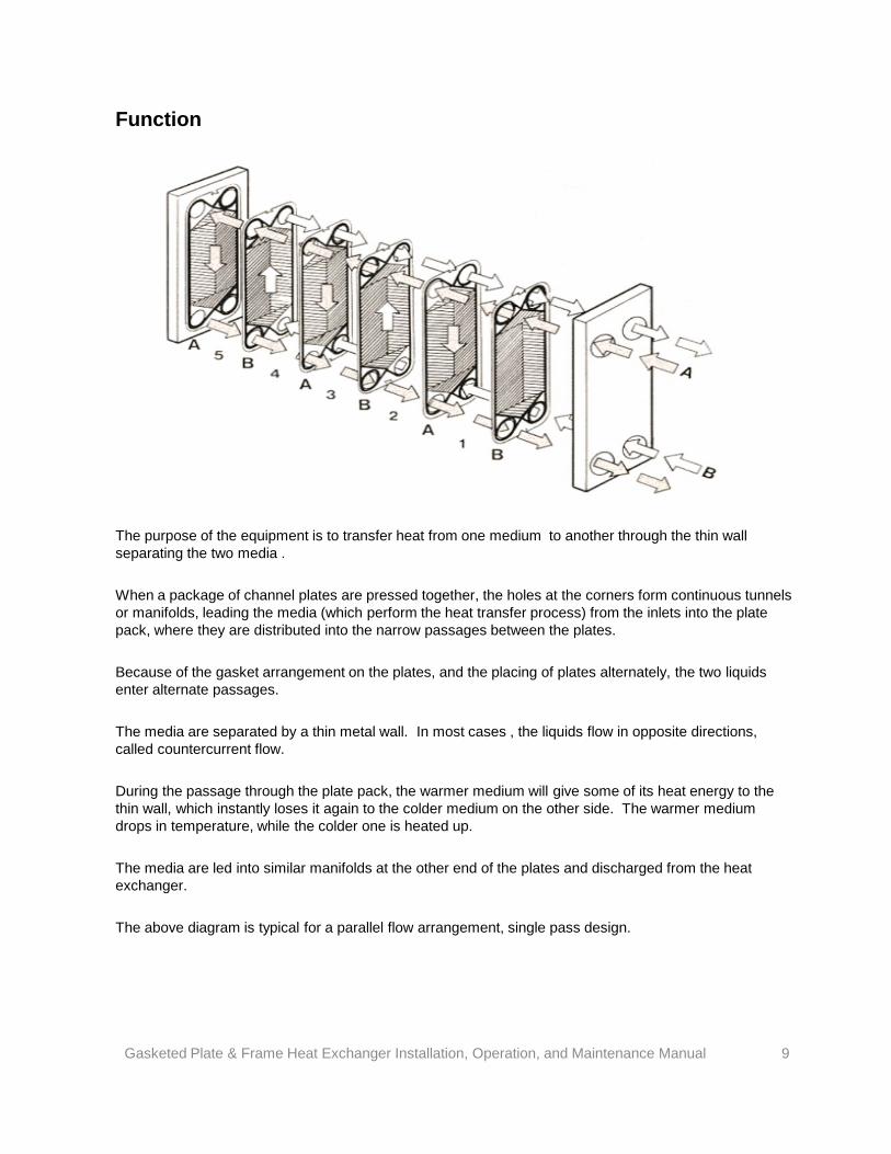
Function
The purpose of the equipment is to transfer heat from one medium to another through the thin wall separating the two media . When a package of channel plates are pressed together, the holes at the corners form continuous tunnels or manifolds, leading the media (which perform the heat transfer process) from the inlets into the plate pack, where they are distributed into the narrow passages between the plates. Because of the gasket arrangement on the plates, and the placing of plates alternately, the two liquids enter alternate passages. The media are separated by a thin metal wall. In most cases , the liquids flow in opposite directions, called countercurrent flow. During the passage through the plate pack, the warmer medium will give some of its heat energy to the thin wall, which instantly loses it again to the colder medium on the other side. The warmer medium drops in temperature, while the colder one is heated up. The media are led into similar manifolds at the other end of the plates and discharged from the heat exchanger. The above diagram is typical for a parallel flow arrangement, single pass design. Gasketed Plate & Frame Heat Exchanger Installation, Operation, and Maintenance Manual 9
The unique pattern into which the plate material has been formed not only gives strength and rigidity, but greatly increases the rate of the heat transfer from the warmer medium to the metal wall and from the wall to the other medium. The corrugation pattern on the thermal plates induces highly turbulent flow. This turbulence gives strong resistance to the formation of deposits on the plate surface but it cannot always eliminate fouling.
Fouling Fouling may increase the total “wall thickness” substantially and can consist of materials that have a much lower thermal conductivity than the metal plate. Consequently a fouling layer can severely reduce the overall heat transfer rate and increase fluid pressure drop. Reducing fouling will be considered under MAINTENANCE. Fouling is unwanted and can under certain circumstances, be harmful to the heat exchanger, because corrosion may occur under the fouling. All systems, and equipment in them, offer resistance to media flowing through them. Some pressure drop is unavoidable, but for given equipment it should be kept as close as possible to the designed value. The formation of fouling on the heat transfer surfaces instantly leads to a reduction of the free space between the plates. This means that more energy is required to get the desired flow through the heat exchanger. It is clear that the fouling of the surfaces is undesirable. Larger particles and fibers may also be drawn into the heat exchanger and clog it, if strainers or other means of protection have not been used. A reduced ability by the heat exchanger to hold the desired temperatures, in combination with an increased pressure drop on any of the media, indicates that fouling or clogging is taking place.
Gasketed Plate & Frame Heat Exchanger Installation, Operation, and Maintenance Manual 10
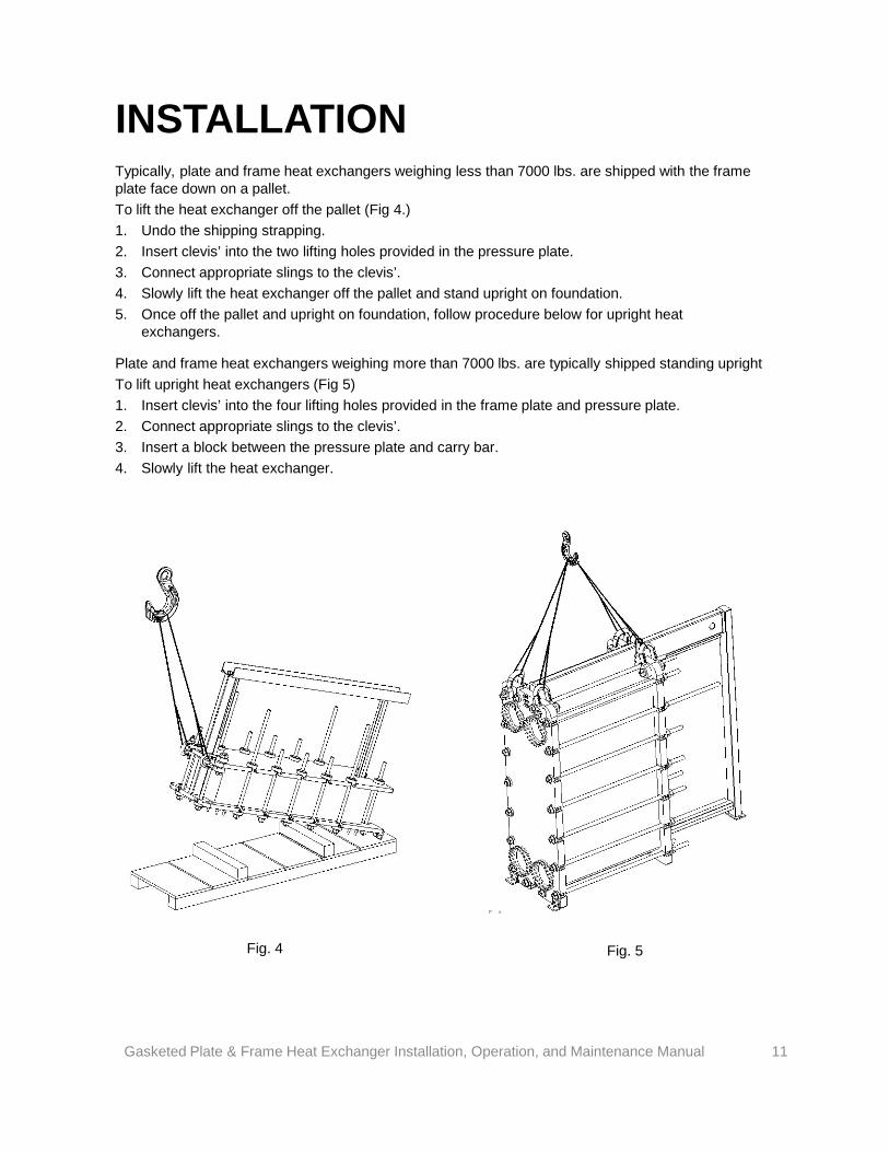
Typically, plate and frame heat exchangers weighing less than 7000 lbs. are shipped with the frame plate face down on a pallet. To lift the heat exchanger off the pallet (Fig 4.) 1. Undo the shipping strapping. 2. Insert clevis’ into the two lifting holes provided in the pressure plate. 3. Connect appropriate slings to the clevis’. 4. Slowly lift the heat exchanger off the pallet and stand upright on foundation. 5. Once off the pallet and upright on foundation, follow procedure below for upright heat
exchangers.
INSTALLATION
Fig. 4
Gasketed Plate & Frame Heat Exchanger Installation, Operation, and Maintenance Manual 11
Plate and frame heat exchangers weighing more than 7000 lbs. are typically shipped standing upright To lift upright heat exchangers (Fig 5) 1. Insert clevis’ into the four lifting holes provided in the frame plate and pressure plate. 2. Connect appropriate slings to the clevis’. 3. Insert a block between the pressure plate and carry bar. 4. Slowly lift the heat exchanger.
Fig. 5
Provide adequate foundation to support the weight of the unit so that it will not settle and cause piping strain. For 1” and 2” port models, the pressure plate should be supported along its length of travel. The unit should be mounted upright using the provided support feet.
WARNING: Do not mount in any other orientation other than intended.
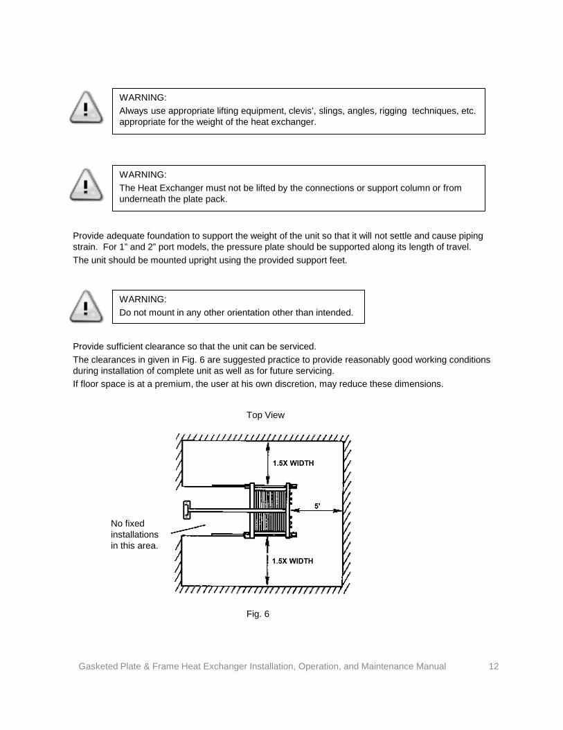
Provide sufficient clearance so that the unit can be serviced. The clearances in given in Fig. 6 are suggested practice to provide reasonably good working conditions during installation of complete unit as well as for future servicing. If floor space is at a premium, the user at his own discretion, may reduce these dimensions.
No fixed installations in this area.
Fig. 6
Gasketed Plate & Frame Heat Exchanger Installation, Operation, and Maintenance Manual 12
WARNING: The Heat Exchanger must not be lifted by the connections or support column or from underneath the plate pack.
WARNING: Always use appropriate lifting equipment, clevis’, slings, angles, rigging techniques, etc. appropriate for the weight of the heat exchanger.
Top View
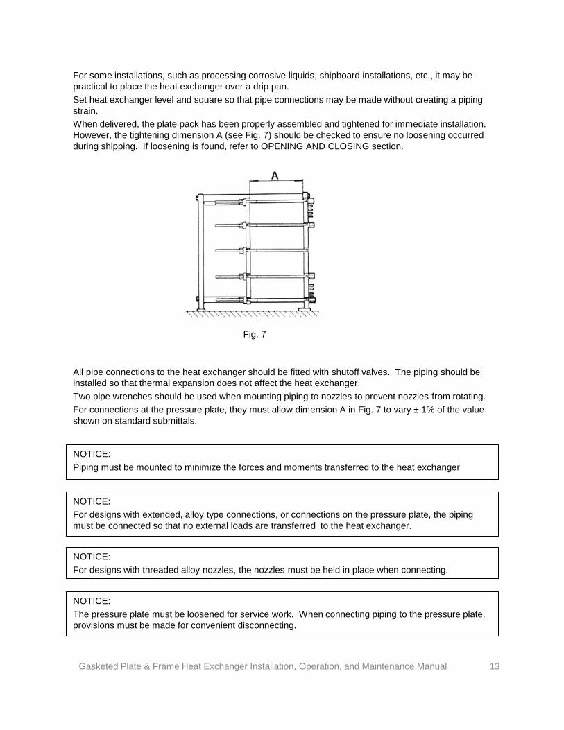
For some installations, such as processing corrosive liquids, shipboard installations, etc., it may be practical to place the heat exchanger over a drip pan. Set heat exchanger level and square so that pipe connections may be made without creating a piping strain. When delivered, the plate pack has been properly assembled and tightened for immediate installation. However, the tightening dimension A (see Fig. 7) should be checked to ensure no loosening occurred during shipping. If loosening is found, refer to OPENING AND CLOSING section.
All pipe connections to the heat exchanger should be fitted with shutoff valves. The piping should be installed so that thermal expansion does not affect the heat exchanger. Two pipe wrenches should be used when mounting piping to nozzles to prevent nozzles from rotating. For connections at the pressure plate, they must allow dimension A in Fig. 7 to vary ± 1% of the value shown on standard submittals.
NOTICE: Piping must be mounted to minimize the forces and moments transferred to the heat exchanger
NOTICE: For designs with extended, alloy type connections, or connections on the pressure plate, the piping must be connected so that no external loads are transferred to the heat exchanger.
NOTICE: For designs with threaded alloy nozzles, the nozzles must be held in place when connecting.
Fig. 7
NOTICE: The pressure plate must be loosened for service work. When connecting piping to the pressure plate, provisions must be made for convenient disconnecting.
Gasketed Plate & Frame Heat Exchanger Installation, Operation, and Maintenance Manual 13
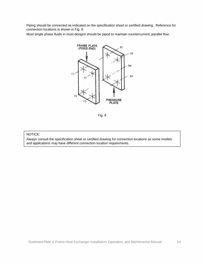
NOTICE: Always consult the specification sheet or certified drawing for connection locations as some models and applications may have different connection location requirements.
Piping should be connected as indicated on the specification sheet or certified drawing. Reference for connection locations is shown in Fig. 8. Most single phase fluids in most designs should be piped to maintain countercurrent, parallel flow.
Fig. 8
Gasketed Plate & Frame Heat Exchanger Installation, Operation, and Maintenance Manual 14
Provide instrumentation in all piping to and from the unit. Locate them with minimum recommended separation distances and straight runs of pipe from any elbows, control valves, pumps, reducers, tees, etc. Provide air vents near top of piping, so unit can be purged of air, and drains as required in piping..
Inspect all openings in exchanger for foreign material. Do not store units outdoors with nozzle or flange protectors removed from unit, since water may enter and cause severe damage due to freezing. To prevent plugging of plate channels with sand or refuse, be sure entire system is clean before starting operation.
WARNING: During times of shutdown, volumetric expansion can occur. It is recommended to install properly sized relief valves on both sides of the heat exchanger.
Most systems are grounded in some way and many users choose to use the plate & frame heat exchanger as the grounding point since it may one of the larger pieces of equipment. Some models may have a tapped hole in the frame plate for a customer supplied grounding lug.
WARNING: Splash guard should not be removed for operation.
NOTICE: If fluids are “dirty”, a filter or strainer should be installed at the inlets prior to the heat exchanger to avoid potential plugging.
Gasketed Plate & Frame Heat Exchanger Installation, Operation, and Maintenance Manual 15
NOTICE: Always follow standard, recommended welding practices . Never weld directly to or on the heat exchanger.
When placing a unit in operation, open the vent connections and start to circulate the cold fluid by slowly opening the valves. Be sure that the passages in the exchanger are filled with the cold fluid before closing the air vents. The hot fluid should then be introduced in the same manner until all passages are filled with fluid. When empty or cold, do not admit hot fluid to the unit suddenly. Do not shock the unit with cold fluid when unit is hot.
OPERATION
CAUTION: Fluids must be gradually introduced to the unit. Failure to do so can cause damage.
During start-up there may be some leakage until the plates and gaskets reach their working temperature. Should leakage continue, check that dimension “A” in Fig. 7 is correct within ± 1% of the value shown on the drawings or nameplate.
CAUTION: The Plate & Frame must never be subjected to pressure greater than the maximum differential or design pressure or to temperatures below or above those stated on the nameplate.
CAUTION: Sudden rises in pressure may cause leakage and/or damage plates and gaskets.
NOTICE: Ensure no debris from the system enters the heat exchanger at start-up. It may be necessary to bypass the heat exchanger until system is flushed clean.
Gasketed Plate & Frame Heat Exchanger Installation, Operation, and Maintenance Manual 16
STORAGE
NOTICE: Cover the heat exchanger with dark plastic to protect it from welding light and dirt (rubber gaskets are sensitive to welding light).
NOTICE: Do not store organic solvents or acids in the room or near the heat exchanger. Avoid heat or ultraviolet radiation.
Equipment should be protected from the elements and not subject to extreme cold or heat. Should it be necessary to store the heat exchanger for a longer period (1 month or more), certain precautions should be taken in order to prevent unnecessary damage to the equipment. It is advisable to empty the heat exchanger and clean the plates. Preferably the heat exchanger should be stored inside a room with a temperature around 60 F to 70 F and a humidity maximum of 70%. There should absolutely not be any ozone producing equipment in the room, like electric motors or arc welding equipment, since ozone destroys many rubber materials. Do not store organic solvents or acids in the room. Avoid extreme cold, heat or ultraviolet radiation. Loosen the tightening bolts slightly. A general rule of thumb is to no more than the plate pack tightening dimension +10%. The tightening bolts should not be loosened to such an extent that dirt is allowed to enter between the thermal plates. It is recommended that a warning notice be attached to the equipment that the tightening bolts need adjustment before putting back into service. Cover the heat exchanger with non-transparent plastic, however, still allow for air circulation. If not connected to the pipe system, the connections should be covered. Applying a rust preventative to all unpainted carbon steel machined parts is a good precaution. If heat exchanger must be stored outdoors, above should be followed as much as practical. In addition, the heat exchanger should be protected against the weather by use of a wooden box with a waterproof lining or similar. Avoid extreme cold, heat or ultraviolet radiation.
Gasketed Plate & Frame Heat Exchanger Installation, Operation, and Maintenance Manual 17
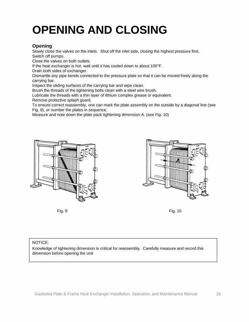
OPENING AND CLOSING Opening Slowly close the valves on the inlets. Shut off the inlet side, closing the highest pressure first. Switch off pumps. Close the valves on both outlets. If the heat exchanger is hot, wait until it has cooled down to about 100°F. Drain both sides of exchanger. Dismantle any pipe bends connected to the pressure plate so that it can be moved freely along the carrying bar. Inspect the sliding surfaces of the carrying bar and wipe clean. Brush the threads of the tightening bolts clean with a steel wire brush. Lubricate the threads with a thin layer of lithium complex grease or equivalent. Remove protective splash guard. To ensure correct reassembly, one can mark the plate assembly on the outside by a diagonal line (see Fig. 9), or number the plates in sequence. Measure and note down the plate pack tightening dimension A. (see Fig. 10)
NOTICE: Knowledge of tightening dimension is critical for reassembly. Carefully measure and record this dimension before opening the unit
Fig. 9 Fig. 10
Gasketed Plate & Frame Heat Exchanger Installation, Operation, and Maintenance Manual 18
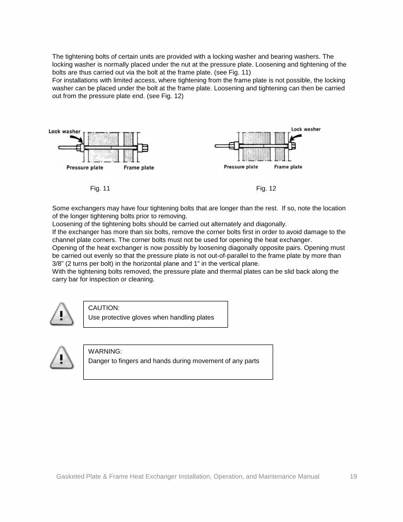
The tightening bolts of certain units are provided with a locking washer and bearing washers. The locking washer is normally placed under the nut at the pressure plate. Loosening and tightening of the bolts are thus carried out via the bolt at the frame plate. (see Fig. 11) For installations with limited access, where tightening from the frame plate is not possible, the locking washer can be placed under the bolt at the frame plate. Loosening and tightening can then be carried out from the pressure plate end. (see Fig. 12)
Some exchangers may have four tightening bolts that are longer than the rest. If so, note the location of the longer tightening bolts prior to removing. Loosening of the tightening bolts should be carried out alternately and diagonally. If the exchanger has more than six bolts, remove the corner bolts first in order to avoid damage to the channel plate corners. The corner bolts must not be used for opening the heat exchanger. Opening of the heat exchanger is now possibly by loosening diagonally opposite pairs. Opening must be carried out evenly so that the pressure plate is not out-of-parallel to the frame plate by more than 3/8” (2 turns per bolt) in the horizontal plane and 1” in the vertical plane. With the tightening bolts removed, the pressure plate and thermal plates can be slid back along the carry bar for inspection or cleaning.
CAUTION: Use protective gloves when handling plates
WARNING: Danger to fingers and hands during movement of any parts
Fig. 11 Fig. 12
Gasketed Plate & Frame Heat Exchanger Installation, Operation, and Maintenance Manual 19
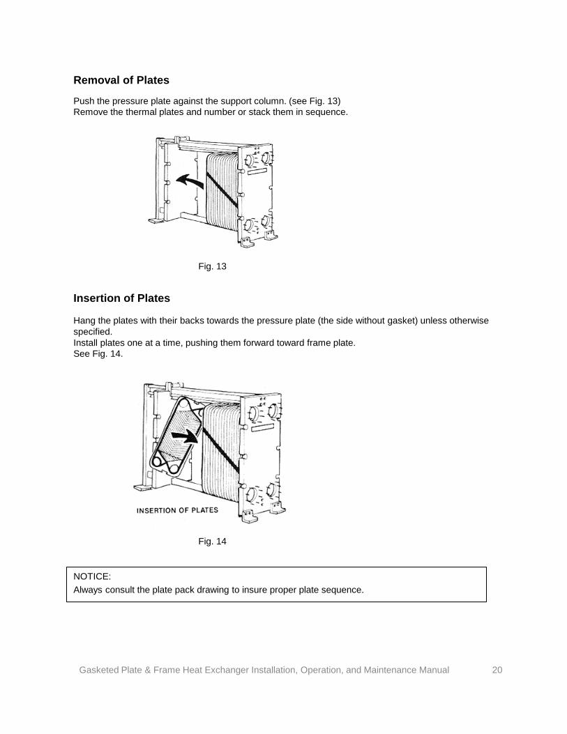
Removal of Plates
Push the pressure plate against the support column. (see Fig. 13) Remove the thermal plates and number or stack them in sequence.
Fig. 13
Insertion of Plates
Hang the plates with their backs towards the pressure plate (the side without gasket) unless otherwise specified. Install plates one at a time, pushing them forward toward frame plate. See Fig. 14.
NOTICE: Always consult the plate pack drawing to insure proper plate sequence.
Fig. 14
Gasketed Plate & Frame Heat Exchanger Installation, Operation, and Maintenance Manual 20
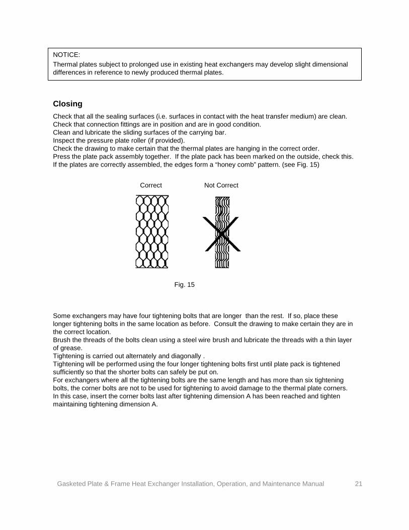
Closing Check that all the sealing surfaces (i.e. surfaces in contact with the heat transfer medium) are clean. Check that connection fittings are in position and are in good condition. Clean and lubricate the sliding surfaces of the carrying bar. Inspect the pressure plate roller (if provided). Check the drawing to make certain that the thermal plates are hanging in the correct order. Press the plate pack assembly together. If the plate pack has been marked on the outside, check this. If the plates are correctly assembled, the edges form a “honey comb” pattern. (see Fig. 15)
Some exchangers may have four tightening bolts that are longer than the rest. If so, place these longer tightening bolts in the same location as before. Consult the drawing to make certain they are in the correct location. Brush the threads of the bolts clean using a steel wire brush and lubricate the threads with a thin layer of grease. Tightening is carried out alternately and diagonally . Tightening will be performed using the four longer tightening bolts first until plate pack is tightened sufficiently so that the shorter bolts can safely be put on. For exchangers where all the tightening bolts are the same length and has more than six tightening bolts, the corner bolts are not to be used for tightening to avoid damage to the thermal plate corners. In this case, insert the corner bolts last after tightening dimension A has been reached and tighten maintaining tightening dimension A.
NOTICE: Thermal plates subject to prolonged use in existing heat exchangers may develop slight dimensional differences in reference to newly produced thermal plates.
Correct Not Correct
Fig. 15
Gasketed Plate & Frame Heat Exchanger Installation, Operation, and Maintenance Manual 21
After all the bolts are now in place, continue tightening alternately and diagonally to the tightening dimension A. Check the tightening dimension A during closing in at least four locations. During tightening, the rear pressure plate must not be out of parallel to the frame plate by more than 3/8“ in the horizontal plane and 1” in the vertical plane. Check the final tightening dimension A in at least four locations. The distance between the plate pack lengths measured at adjacent bolts should not exceed 0.08“ when tightening dimension A is <39.5” and 0.16” when tightening dimension A is >39.5”. The plate pack length at all bolts should not differ by more than 1%. The maximum tightening dimension A can be exceeded in some cases. The tightening can be stopped at A + 2% and pressure tested. Replace the protective splash guard.
NOTICE: Do not go below the minimum tightening dimension A without consulting the factory as damage to the thermal plates may occur.
NOTICE: If the thermal plate count has changed, a new tightening dimension is required and it is recommended to note this.
Gasketed Plate & Frame Heat Exchanger Installation, Operation, and Maintenance Manual 22

Cleaning - General
MAINTENANCE
WARNING: Care must be exercised when handling certain fluids. Follow manufacturer’s instructions. Use eye and skin protection. Wear a respirator when required.
Cleaning the unit may be accomplished by either backflushing, circulating cleaning agents in unit or by disassembly. If the fluid contains suspended foreign material, deposits can accumulate in the flow passages. Under these circumstances, backflushing may be adequate to clean unit. If this method is ineffective for the removal of deposit, you may want to circulate buffered cleaning agents in unit to remove scale or disassemble unit for manual cleaning.
Cleaning Procedures To disassemble unit for manual cleaning follow steps given earlier for OPENING. Plates can be cleaned while hanging on frame or removed depending on how much work is required. A fiber type brush is recommended but as a last resort use a brush of similar material to thermal plates. After brushing, rinse each plate with water. For better sealing wipe all gaskets dry.
NOTICE: Ensure cleaning agents are compatible with materials. Under no circumstances should hydrochloric acid or water with more than 300 ppm Cl be used for the preparation of cleaning solutions with stainless steel thermal plates.
NOTICE: Ensure frame components, such as carry/guide bars and support column, are protected against chemicals
NOTICE: Do not use brushes with carbon steel bristles or steel wool.
NOTICE: Be careful not to damage gaskets if they are to be reused
NOTICE: In general, the following solvents should not be used in contact with gaskets • Ketones (e.g. Ethylacetate, Butylacetate) • Esters (e.g. Ethylacetate, Butylacetate) • Halogenated hydrocarbons (e.g. Chlorothene, Carbon tetrachloride, Freons) • Aromatics (e.g. Benzene, Toluene)
Gasketed Plate & Frame Heat Exchanger Installation, Operation, and Maintenance Manual 23
Gasketed Plate & Frame Heat Exchanger Installation, Operation, and Maintenance Manual 24
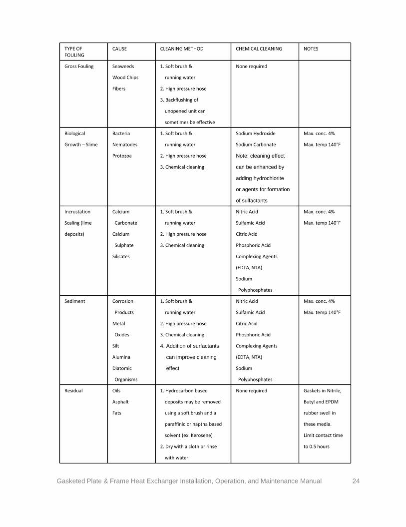
TYPE OF FOULING
CAUSE CLEANING METHOD CHEMICAL CLEANING NOTES
Gross Fouling Seaweeds 1. Soft brush & None required
Wood Chips running water
Fibers 2. High pressure hose
3. Backflushing of
unopened unit can
sometimes be effective
Biological Bacteria 1. Soft brush & Sodium Hydroxide Max. conc. 4%
Growth – Slime Nematodes running water Sodium Carbonate Max. temp 140°F
Protozoa 2. High pressure hose Note: cleaning effect
3. Chemical cleaning can be enhanced by
adding hydrochlorite
or agents for formation
of sulfactants
Incrustation Calcium 1. Soft brush & Nitric Acid Max. conc. 4%
Scaling (lime Carbonate running water Sulfamic Acid Max. temp 140°F
deposits) Calcium 2. High pressure hose Citric Acid
Sulphate 3. Chemical cleaning Phosphoric Acid
Silicates Complexing Agents
(EDTA, NTA)
Sodium
Polyphosphates
Sediment Corrosion 1. Soft brush & Nitric Acid Max. conc. 4%
Products running water Sulfamic Acid Max. temp 140°F
Metal 2. High pressure hose Citric Acid
Oxides 3. Chemical cleaning Phosphoric Acid
Silt 4. Addition of surfactants Complexing Agents
Alumina can improve cleaning (EDTA, NTA)
Diatomic effect Sodium
Organisms Polyphosphates
Residual Oils 1. Hydrocarbon based None required Gaskets in Nitrile,
Asphalt deposits may be removed Butyl and EPDM
Fats using a soft brush and a rubber swell in
paraffinic or naptha based these media.
solvent (ex. Kerosene) Limit contact time
2. Dry with a cloth or rinse to 0.5 hours
with water
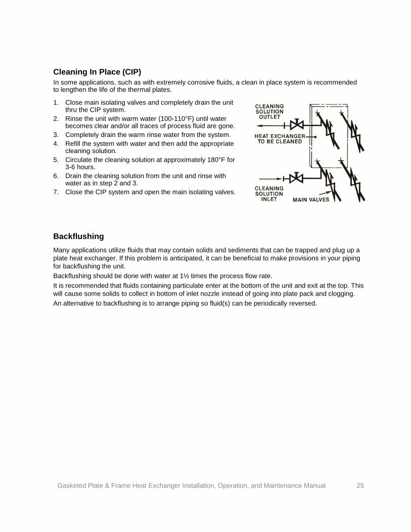
Cleaning In Place (CIP) In some applications, such as with extremely corrosive fluids, a clean in place system is recommended to lengthen the life of the thermal plates.
1. Close main isolating valves and completely drain the unit thru the CIP system.
2. Rinse the unit with warm water (100-110°F} until water becomes clear and/or all traces of process fluid are gone.
3. Completely drain the warm rinse water from the system. 4. Refill the system with water and then add the appropriate
cleaning solution. 5. Circulate the cleaning solution at approximately 180°F for
3-6 hours. 6. Drain the cleaning solution from the unit and rinse with
water as in step 2 and 3. 7. Close the CIP system and open the main isolating valves.
Backflushing Many applications utilize fluids that may contain solids and sediments that can be trapped and plug up a plate heat exchanger. If this problem is anticipated, it can be beneficial to make provisions in your piping for backflushing the unit. Backflushing should be done with water at 1½ times the process flow rate. It is recommended that fluids containing particulate enter at the bottom of the unit and exit at the top. This will cause some solids to collect in bottom of inlet nozzle instead of going into plate pack and clogging. An alternative to backflushing is to arrange piping so fluid(s) can be periodically reversed.
Gasketed Plate & Frame Heat Exchanger Installation, Operation, and Maintenance Manual 25
Gasket Replacement Before removing the old gaskets, new gaskets, glue (if required), cleaning and degreasing fluid should be obtained. A suitable gasket glue is 3M™ Scotch-Grip™ plastic adhesive 1099. Some suitable gasket groove cleaning fluids are methyl ethyl ketone, petroleum naphtha, and carbon tetrachloride. A suitable degreasing fluid is trichloroethylene.
WARNING: Care must be exercised when handling these fluids. Follow manufacturers instructions. Use eye and skin protection. Wear a respirator when required.
NOTICE: Gasket may have to be stretched prior to installation to fit the gasket groove. Avoid excess stretching as damage to gasket can result.
Gasket Replacement – Glued Gasket Type
1. Remove the old gaskets. 2. Clean the gasket grooves of the thermal plates carefully with cleaning fluid. 3. Degrease the gaskets with a cloth moistened with the degreasing fluid. 4. Apply a thin even coating of glue in the bottom of the gasket groove.
NOTICE: Large excess of glue is undesirable as this can lead to joining of adjacent plates and/or deformation of the plates due to hardened glue interfering at metal contact points.
NOTICE: Follow glue manufacturer’s instructions and ensure compatible with materials and fluids..
NOTICE: Some double wall models, semi-welded models and designs with connections at the pressure plate may have special ring gaskets. Consult factory for assistance in replacement of these if necessary.
Gasketed Plate & Frame Heat Exchanger Installation, Operation, and Maintenance Manual 26
5. Insert the gasket in the gasket groove, first in the plate ends and after that in the straight gasket grooves along the side of the plate. 6. Evenly press the gasket well down into the gasket groove. Care shall be taken that the gasket is correctly placed in the gasket groove with no part of it being outside the groove. If necessary, tape can be used to keep gasket from lifting and twisting until glue hardens. Remove tape prior to installing thermal plates into heat exchanger. 7. The thermal plates should then be placed horizontally on a table during gluing. Stack the plates as they are finished. The back of the gasket groove may be powdered with talcum powder in order to prevent the plates from sticking together. Powder may need to be rinsed prior to operation. 8. After all the thermal plates have had the gaskets glued in place, reassemble the plate pack and tighten. The glue will cure at the heat exchanger operating temperature.
Gasket Replacement – Glueless Gasket Type
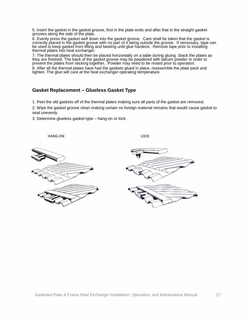
1. Peel the old gaskets off of the thermal plates making sure all parts of the gasket are removed. 2. Wipe the gasket groove clean making certain no foreign material remains that would cause gasket to seat unevenly. 3. Determine glueless gasket type – hang-on or lock
HANG-ON LOCK
Gasketed Plate & Frame Heat Exchanger Installation, Operation, and Maintenance Manual 27
4. For hang-on type gaskets, attach the hang-on type gasket to the plate using the gasket prongs which slip under the edge of the plate to hold the gasket securely in alignment in the gasket groove. For lock type gaskets, place the lock type gasket with stud type projections downwards into the gasket groove. Attach the lock type gasket to the plate via the stud projection being forced through holes on the outer edge of the thermal plates. A tool may be necessary to push the stud through the hole in the plate. For either hang-on or lock type gaskets, it may be necessary to use a small amount of glue along the diagonal gasket groove across the port hole. 5. Before closing the plate pack, make certain that the gaskets are in the correct position to assure proper alignment and insure a good seal. 6. When the plate heat exchanger is then assembled and tightened, the gasket provides a tight seal around the plate.
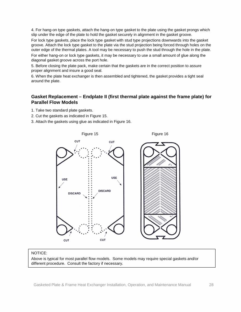
Gasket Replacement – Endplate II (first thermal plate against the frame plate) for Parallel Flow Models 1. Take two standard plate gaskets. 2. Cut the gaskets as indicated in Figure 15. 3. Attach the gaskets using glue as indicated in Figure 16.
Figure 15 Figure 16
NOTICE: Above is typical for most parallel flow models. Some models may require special gaskets and/or different procedure. Consult the factory if necessary.
Gasketed Plate & Frame Heat Exchanger Installation, Operation, and Maintenance Manual 28
FAULT DETECTION WARNING: Always relieve pressure before removing splash guard. Test at room temperature with clear water where possible. If not possible, proper precautions must be taken (special clothing, equipment, etc…) to protect personnel from injury due to escaping fluid.
NOTICE: On a plate & frame heat exchanger, extreme and sudden temperature changes may sometimes cause a temporary leakage. A typical example is a sudden shutting-off of the hot medium flow. The heat exchanger will normally seal again, as soon as the temperatures of the equipment have stabilized.
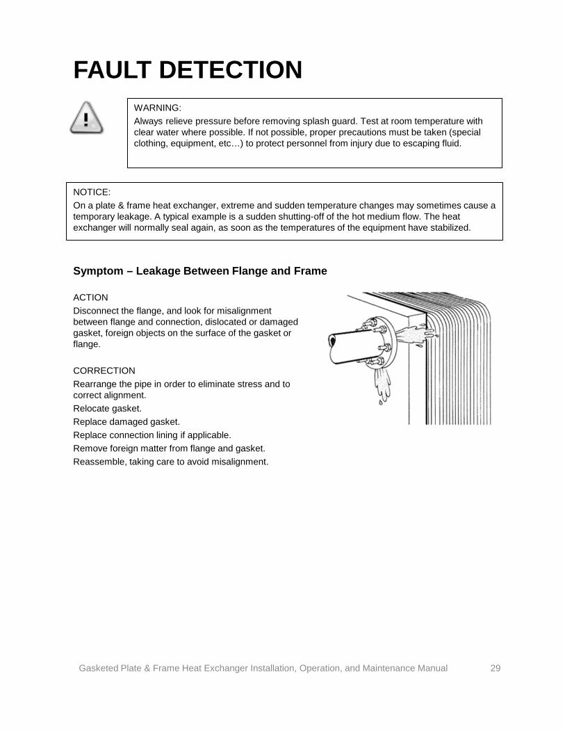
Symptom – Leakage Between Flange and Frame
ACTION Disconnect the flange, and look for misalignment between flange and connection, dislocated or damaged gasket, foreign objects on the surface of the gasket or flange. CORRECTION Rearrange the pipe in order to eliminate stress and to correct alignment. Relocate gasket. Replace damaged gasket. Replace connection lining if applicable. Remove foreign matter from flange and gasket. Reassemble, taking care to avoid misalignment.
Gasketed Plate & Frame Heat Exchanger Installation, Operation, and Maintenance Manual 29
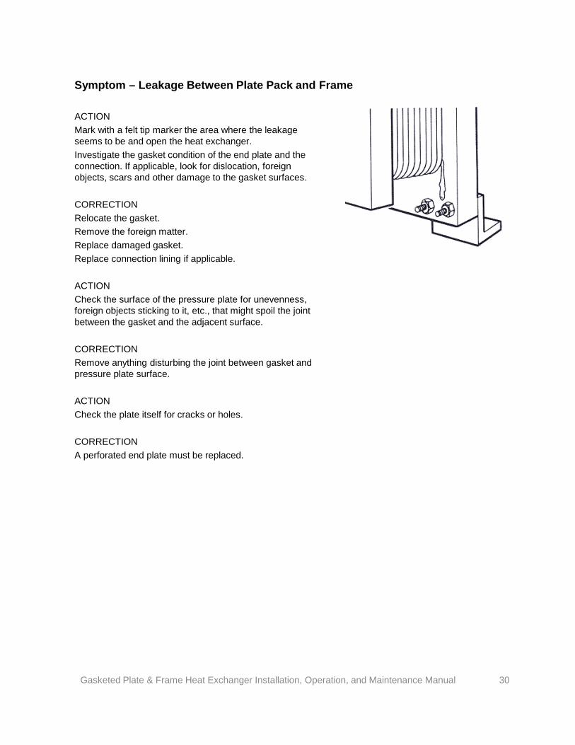
Symptom – Leakage Between Plate Pack and Frame
ACTION Mark with a felt tip marker the area where the leakage seems to be and open the heat exchanger. Investigate the gasket condition of the end plate and the connection. If applicable, look for dislocation, foreign objects, scars and other damage to the gasket surfaces. CORRECTION Relocate the gasket. Remove the foreign matter. Replace damaged gasket. Replace connection lining if applicable. ACTION Check the surface of the pressure plate for unevenness, foreign objects sticking to it, etc., that might spoil the joint between the gasket and the adjacent surface. CORRECTION Remove anything disturbing the joint between gasket and pressure plate surface. ACTION Check the plate itself for cracks or holes. CORRECTION A perforated end plate must be replaced.
Gasketed Plate & Frame Heat Exchanger Installation, Operation, and Maintenance Manual 30
Symptom – Mixing of Media
ACTION Check that the piping is connected to the heat exchanger at correct locations. CORRECTION Relocate piping to correct connections. ACTION Open the lower connection on one side, raise pressure on the other side and by looking into the open connection try to detect any liquid from the pressurized side leaking in, and if so, approximately how far into the plate pack the leakage is located. If no leakage is detected, the reason for the mixing of the media must be sought elsewhere. ACTION If a leakage was detected, note the position of the leakage along the plate pack and then open the plate heat exchanger. ACTION Before starting on the plates themselves, check that the corner areas between the ring and the field gaskets are clear, and the leakage slots are open. This ensures that any leakage is out of the plate heat exchanger and is to atmosphere. Therefore no pressure can build up to force the media across the gasket sealing off the other liquid. CORRECTION All deposits or material which can block the free exit from the area must be removed. If the leak channels of the gasket have been destroyed, they must be reopened with a suitable tool, or the gasket replaced. ACTION If it has not been possible to locate the leakage as described above, it will be necessary to check each single plate for possible perforations, using any of the following methods: Put a strong light behind the plate and watch for light coming through fine holes or cracks. Use a magnifying glass to check suspect area. Use a chemical penetrant, after having cleaned the plate well. CORRECTION Plates with holes are, generally speaking, destroyed and must be replaced. For temporary solution with reduced number of plates, see LEAKAGE BETWEEN THERMAL PLATES TO OUTSIDE.
Gasketed Plate & Frame Heat Exchanger Installation, Operation, and Maintenance Manual 31
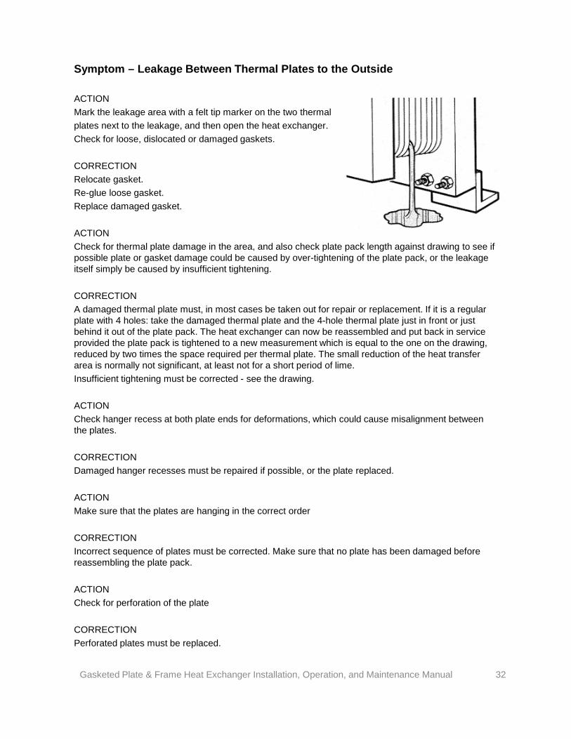
Symptom – Leakage Between Thermal Plates to the Outside
ACTION Mark the leakage area with a felt tip marker on the two thermal plates next to the leakage, and then open the heat exchanger. Check for loose, dislocated or damaged gaskets. CORRECTION Relocate gasket. Re-glue loose gasket. Replace damaged gasket. ACTION Check for thermal plate damage in the area, and also check plate pack length against drawing to see if possible plate or gasket damage could be caused by over-tightening of the plate pack, or the leakage itself simply be caused by insufficient tightening. CORRECTION A damaged thermal plate must, in most cases be taken out for repair or replacement. If it is a regular plate with 4 holes: take the damaged thermal plate and the 4-hole thermal plate just in front or just behind it out of the plate pack. The heat exchanger can now be reassembled and put back in service provided the plate pack is tightened to a new measurement which is equal to the one on the drawing, reduced by two times the space required per thermal plate. The small reduction of the heat transfer area is normally not significant, at least not for a short period of lime. Insufficient tightening must be corrected - see the drawing. ACTION Check hanger recess at both plate ends for deformations, which could cause misalignment between the plates. CORRECTION Damaged hanger recesses must be repaired if possible, or the plate replaced. ACTION Make sure that the plates are hanging in the correct order CORRECTION Incorrect sequence of plates must be corrected. Make sure that no plate has been damaged before reassembling the plate pack. ACTION Check for perforation of the plate CORRECTION Perforated plates must be replaced.
Gasketed Plate & Frame Heat Exchanger Installation, Operation, and Maintenance Manual 32
Symptom – Pressure Drop has Increased
ACTION Check that all valves are open including non return valves. Measure the pressure before and after the heat exchanger, and the flow rate with minimum separation distances from any elbows, tees, etc. For viscous media, a membrane manometer with a diameter of at least 30 millimeters should be used. Compare the pressure drop observed with the one specified for the actual flow rate. (See data print out). ACTION If the pressure drop is higher than that specified, the temperature profile should also be checked. CORRECTION See next paragraph ACTION If the thermometer reading corresponds to those specified, the heat transfer surface is probably clean enough, but the inlet to the heat exchanger may be clogged by some objects. CORRECTION Open the apparatus and take out whatever is clogging the passage, or use the backflush system , if there is one, to rinse out the debris. ACTION If the thermometer readings are not corresponding to the specified, heat transfer is obviously dropping below specifications because of deposits on the heat transfer surface, which at the same time also increase the pressure drop since the passage becomes narrower. CORRECTION If the pressure drop is corresponding to the specifications, there is no need for any action. ACTION If the pressure drop is lower than specified, the pump capacity is too small or the observation is wrong. CORRECTION See pump instruction manual.
Gasketed Plate & Frame Heat Exchanger Installation, Operation, and Maintenance Manual 33
Xylem
1) The tissue in plants that brings water upward from the roots;2) a leading global water technology company.
We’re a global team unified in a common purpose: creating advanced technology solutions to the world’s water challenges. Developing new technologies that will improve the way water is used, conserved, and re-used in the future is central to our work. Our products and services move, treat, analyze, monitor and return water to the environment, in public utility, industrial, residential and commercial building services settings. Xylem also provides a leading portfolio of smart metering, network technologies and advanced analytics solutions for water, electric and gas utilities. In more than 150 countries, we have strong, long-standing relationships with customers who know us for our powerful combination of leading product brands and applications expertise with a strong focus on developing comprehensive, sustainable solutions.
For more information on how Xylem can help you, go to www.xylem.com
Standard Xchange is a trademark of Xylem Inc. or one of its subsidiaries.
© 2018 Xylem Inc. 104-70 REVB September 2018
Xylem www.xylem.com/standardxchange