platform for multiagent application development
TRANSCRIPT

728 IEEE TRANSACTIONS ON INDUSTRIAL INFORMATICS, VOL. 11, NO. 3, JUNE 2015
Platform for Multiagent Application DevelopmentIncorporating Accurate Communications Modeling
Fidelis Perkonigg, Djordje Brujic, Member, IEEE, and Mihailo Ristic, Member, IEEE
Abstract—Multiagent systems are widely recognized as amethod of choice for realization of distributed time-critical appli-cations for the smart grid. However, no general solutions havebeen proposed for the difficult task of system development andvalidation, ready for deployment, which would fully account forthe underlying communication network performance. We pro-pose a novel platform designed for this purpose, which inte-grates a standard multiagent development framework [Java AgentDevelopment (JADE)] and an industry standard communicationsnetwork simulator (OPNET modeler). It was realized throughgeneric extensions of the JADE framework to provide discreteevent scheduling capabilities, while the OPNET modeler wasextended to provide a generic method of associating the networknodes with agents running in JADE. The adopted method adheresto the high-level architecture standard. Importantly, applicationsdeveloped using this platform may be deployed on the target sys-tem without manual modifications. A distributed protection appli-cation is presented and the performance is analyzed with respect tocandidate agent behaviors and communication scenarios, demon-strating that the feasibility of the application critically depends onthe choices made during its design and implementation.
Index Terms—Communication networks, multiagent systems(MASs), smart grid.
I. INTRODUCTION
M ULTIAGENT systems (MASs) are now widely recog-nized as the preferred approach for the development
of distributed applications, which involve multiple autonomousunits that communicate with each other, such that their coordi-nated actions address a common goal. In recent years, MASshave become increasingly important in the context of powersystems, particularly within the concept of smart grid [1], whereintelligent agent technology was shown to be a promisingmethod to automate numerous tasks related to grid manage-ment and control. Distributed applications for the smart gridmay involve autonomous nodes that are physically separatedby tens or even hundreds of kilometers and rely on the avail-able data networks for communication [1]–[3]. This is seen
Manuscript received June 16, 2014; revised February 09, 2015; acceptedApril 15, 2015. Date of publication April 30, 2015; date of current ver-sion June 02, 2015. This work was supported by the Energy Programme ofthe Engineering and Physical Sciences Research Council (EPSRC) SupergenHiDEF Project EP/G031681/1, which is a Research Councils United Kingdom(RCUK) cross-council initiative led by EPSRC. Paper no. TII-14-1349.
F. Perkonigg is with the Department of Computing, Imperial CollegeLondon, London SW7 2AZ, U.K. (e-mail: [email protected]).
D. Brujic and M. Ristic are with the Department of MechanicalEngineering, Imperial College London, London SW7 2AZ, U.K. (e-mail:[email protected]; [email protected]).
Color versions of one or more of the figures in this paper are available onlineat http://ieeexplore.ieee.org.
Digital Object Identifier 10.1109/TII.2015.2428633
as a significantly more flexible alternative than the traditionalcentralized supervisory control and data acquisition (SCADA)systems [1], [2]. For time-critical applications, such as grid pro-tection and control, communication delays are a key factor indetermining the feasibility and reliability of a particular dis-tributed application. Examples of distributed applications basedon MAS include power system protection [1], restoration [4],[5], diagnostics [5], voltage control [6], and control of micro-grids [7]. Safety, robustness, and performance characteristicsunder different network traffic conditions are clearly key issuesto address when attempting to develop a scheme of this type.However, the process of development, verification, and deploy-ment of time-critical MAS applications has not been adequatelyaddressed to date.
Fig. 1 shows the development stages for such applica-tion, starting with the prototype design of the control methodand its analysis using simulation. This results in the speci-fication of performance parameters and constraints (such aspermissible latencies) in which the implemented method mustmeet. The application code will then be implemented usingthe chosen programming language and the run-time platform.Multiagent development platforms, such as ZEUS [8] or JavaAgent Development (JADE) [9], have been adopted by numer-ous researchers in the field of power systems for this purpose[1]–[7], [10], [11].
At the implementation stage, a number of critical choicesand tradeoffs have to be made, including specific agent behav-iors, choice of physical network nodes on which certain criticalagents are running, communication protocols, and quality-of-service (QoS) strategies. The implemented application codealso needs to be analyzed in relation to the specific networkcomponents (routers and switches) and data traffic conditionsfor the target communication network. Geographic dispersionof the target hardware and the risks of damage to vital equip-ment make it imperative to conduct testing and validationoffline.
The deployment on the distributed target system requiresfully tested application code and no (or a very minimum) man-ual code modification. With this in mind, the introduction ofMAS to the power industry makes the whole developmentlife cycle of time-critical control and protection applicationssignificantly more challenging.
Previous research related to smart grid has mainly focused onprototype design and simulation of distributed control methods[12]–[14], but the need to test and validate the implementedapplications, in a coded form ready for deployment, has notbeen adequately addressed. This forms the main motivation forthe work presented in this paper.
1551-3203 © 2015 IEEE. Translations and content mining are permitted for academic research only. Personal use is also permitted, but republication/redistributionrequires IEEE permission. See http://www.ieee.org/publications_standards/publications/rights/index.html for more information.

PERKONIGG et al.: PLATFORM FOR MULTIAGENT APPLICATION DEVELOPMENT 729
Fig. 1. Stages of MAS application development, distinguishing simulationof functional prototypes from application code development, and validationaddressed in this work.
Systems such as electric power and communication syn-chronizing simulator (EPOCHS) [12] and global event-drivenco-simulation platform (GECO) [13] have been designed toimprove simulation of distributed control prototypes, by com-bining two distinct simulation tools into a single coupledsimulation—a continuous-time power system simulation onone hand, with the NS21 discrete-event communications net-work simulation on the other. However, they do not include amultiagent platform. In EPOCHS, agent functionality is repre-sented using a specially written simulation component, whereasin GECO, it is represented within NS2 as parts of the net-work node models. Thus, neither system involves the actualapplication code.
In this paper, we focus on the implementation, test, and val-idation stages of the process shown in Fig. 1. We propose aplatform combining a complete multiagent framework and afull communication network simulation package. In this way,a time-critical MAS application code may be fully developedand validated in preparation for deployment on a target sys-tem, without further manual modifications. Although our primemotivation was to address the needs arising in the developmentof applications for the smart grid, this work is also relevant fora wide range of other distributed control applications.
In line with other power systems research [1], [2], [4]–[7],[14], [15], we have adopted JADE framework [9], [16] as themultiagent platform and we combined it with an establishedcommunications network simulator (NS) OPNET modeler2.The role of the OPNET modeler is to provide an accuratesimulation of the communications network, under various sce-narios, as an integral part of the target environment. TheJADE framework provides all the necessary the Foundationfor Intelligent Physical Agents (FIPA)-compliant3 middleware
1Network simulator 2. [Online] Available: http://www.isi.edu/nsnam2OPNET, Riverbed Technology. [Online] Availavble: http://www.
riverbed.com3FIPA. (2014). Foundation for Intelligent Physical Agents. a standards
organization of the IEEE Computer Society. [Online] Available: http://www.fipa.org/
for implementation of the agent-based applications and itis supported by a wide range of operating systems runningJava. While it is known that Java employs garbage collectionmechanisms that may disrupt program execution at unpre-dictable times, this issue has been addressed by the real-timespecification for Java [17], for which several implementationsare available.
Several key aspects needed to be resolved to realize this con-cept and they make the key contributions of this paper. First,JADE offers a platform to run agents in real time, but it has noconcept of simulation time; therefore, it needed to be extendedto provide it with discrete-event capabilities. Second, we had toprovide generic means of mapping application agents (runningin JADE) into the OPNET simulation framework, involvingextensions to both JADE framework and OPNET. Finally, syn-chronization and handover of execution between two platformshad to be provided. This was achieved via a runtime infras-tructure (RTI) in accordance with the high-level architecture(HLA) standard [18], [19], which also required the provisionof generic extensions of both the JADE framework and theOPNET modeler.
The adoption of the HLA standard is in common with theapproach used in EPOCHS, GECO, and various other cou-pled simulation systems. However, this work focuses on theintegration between JADE and OPNET and on the extensionsrequired for each of these systems, in order to enable the JADEagent applications, in a coded form deployable on the targetsystem, to run in combination with a discrete event simula-tion of the communications network. In contrast, the design ofEPOCHS and GECO was focused on the issues of combining acontinuous-time power system simulation (e.g., using PSCADand PSLF) with the discrete event simulation of the commu-nications network (e.g., using NS2). Cosimulation of powersystems and communications has been extensively surveyed byMets et al. [14]. The methods proposed in [12] may also be usedin our system to include power system modeling, although thiswas not our objective.
The source code developed as part of this work is availableto researchers from the corresponding author on request. JADE,OPNET, and RTI are also needed to replicate the platform, allfreely available for research.
This paper is organized as follows. Section II describes thedesign, architecture, and implementation of the proposed sys-tem. Section III presents, as an example, the implementationand evaluation of an agent-based zone 3 remote backup relaysupervision system [20], in which the performance analysis inrelation to the choice of protocols and a specific communicationinfrastructure are presented in Section IV. Section V presentsthe conclusion.
II. INTEGRATION OF AGENT AND COMMUNICATION
SIMULATION PLATFORMS
A. Architecture Overview
According to the terminology adopted by the HLA standard[21], a system comprising two or more heterogeneous entitiescoupled with each other is called a federation. Fig. 2 illustrates

730 IEEE TRANSACTIONS ON INDUSTRIAL INFORMATICS, VOL. 11, NO. 3, JUNE 2015
Fig. 2. Overall architecture combining the extended JADE framework, extended OPNET simulation, and the HLA-compliant runtime infrastructure. Additionalsimulations such as power flow or electrical transient simulations can be also added.
the overall architecture of the proposed system, which consistsof the following three main components:
1) JADE;2) OPNET modeler, communications NS;3) RTI.The distributed control application is implemented by the
user agents running in JADE, each associated with a particu-lar node in the simulated communication network (OPNET).The RTI provides common services to all federated systems formessage passing, object management, and time management.Possible inclusion of other simulation tools is indicated in Fig. 2by the dotted line blocks.
Both JADE and OPNET modeler are designed to be stand-alone tools and therefore, it is a considerable challenge tocouple them. OPNET modeler is a discrete-event simulator anduses the concept of simulation time. A discrete-event simulation(DES) maintains a simulation clock and proceeds chronologi-cally from one event to the next. Every event is tagged witha timestamp and kept on an event list until its execution. Theevent with the smallest timestamp is executed next and thendeleted from the list. New events can be added by other events,but their timestamps have to be greater than the current sim-ulation time, i.e., no past events can be scheduled. JADE, onthe other hand, offers a platform to run agents as independentthreads in real time, but there is no concept of simulation timeand simulation events, making it difficult to synchronize itsexecution with the OPNET discrete-event simulator. In orderto make a federation possible, extensions of both JADE andOPNET were developed and realized using strategies of re-implementation, extension of intermediate code, and usage ofexternal APIs. With these extensions, this architecture allowsfor a synchronized execution of MASs and communicationnetwork models.
The original JADE framework was extended as follows(Fig. 2). First, the standard JADE agent class was extended to anew FedAgent class to allow time synchronization. Second, wehave provided a new RTI agent as the means of both controllingthe time advance and interfacing JADE with RTI. Finally, themapping between user agents and the OPNET network nodeswas realized using tables and managed using the RTI agent.
Fig. 3. Illustration of message passing in the federation. A message sent fromuser agent U1–U4 (dashed arrow) is relayed via RTI to the network simulationand generic agents G1 and G4, which are parts of the network node modelsN1 and N4, respecitvely.
The OPNET modeler was extended as follows. First, we havedeveloped the generic agent, implemented as an extension ofthe standard OPNET network node. This provides a genericmodel of the user agents running in JADE. The user agentsare mapped to their corresponding generic agents, the latterbeing used to transmit all messages between agents in JADEvia the correct communication links in the simulated network.Second, integration with RTI was provided based on the HLAstandard [18]. All messages passing between OPNET and RTIare performed by the generic agents via the HLA interface.
With these extensions in place, Fig. 3 illustrates a synchro-nized execution of a multiagent application and a communi-cation network model. The user agents Un (n = 1, 2, 3, . . .)implement the distributed application functionality and thenodes Nn (n = 1, 2, 3, . . .) represent the hardware deviceson which the agents run. The generic agent modelsGn (n = 1, 2, 3, . . .) are generic extensions of the node repre-sentation in OPNET and correspond to specific user agents Un.The overall system runs as a discrete-event simulator, i.e., itproceeds chronologically from one event to the next.
In the illustration in Fig. 3, when the RTI grants time toJADE to run agents that are scheduled for a specific time, U1
sends a message to U4 (indicated by the dotted arrow between

PERKONIGG et al.: PLATFORM FOR MULTIAGENT APPLICATION DEVELOPMENT 731
U1 and U4). Instead of delivering the message directly, JADEsends an interaction to OPNET that initiates a data transfer inthe NS. The message originating from U1 is routed via RTI tothe corresponding generic agent G1, incorporated in the modelof the network node N1. It is then routed through the simulatedcommunications network to the node N4 and the generic agentG4. From G4, the message is then passed via RTI to JADE andto the corresponding user agent U4.
It is also important to remember that the user agents imple-menting the distributed application, when deployed on the tar-get system, will interact with physical local devices by collect-ing measurements and performing control actions. Traditionalsubstation automation solutions involve hardwired analogueand binary connections of the substation controller to spe-cific devices such as switchgear and meters, but an increasingtrend is to employ merging units (MU) communicating to localdevices via the process bus such as IEC61850-9-2 [22] overlocal Ethernet. Performance analysis of such a scheme was ana-lyzed by Crossley et al. [23]. In the absence of the target systemat development time, the local environment may be mod-eled using target environment model agents, also implementedwithin JADE (Fig. 2). These may be designed to communi-cate with the user agents according to relevant standard suchas IEC61850 [22] and used to model the performance of localhardware devices and set up test scenarios. It is also possibleto extend the federation to include other packages. Power sys-tem simulation tools (e.g., PSCAD, MATLAB/Simulink, PSLF,and others) can be added in a similar way as it was shown inEPOCHS [12].
The following sections describe the three components andtheir implementation in more detail.
B. Runtime Infrastructure
The RTI is a program that provides distributed simula-tion modeling services. Some of these services ensure thatall simulation components start at the same time and advancein time in a synchronized manner. Other services offer waysto exchange information between the individual componentsthrough interaction, publish and subscribe mechanisms.
For the RTI, we have adopted the MÄK RTI 4.0.4 imple-mentation (MÄK Technologies, Cambridge, MA, USA) whichadheres to the HLA standard [18], [19]. The initial version ofthe HLA standard HLA 1.3 was published in 1998 and laterbecame an IEEE standard method and is defined under IEEE1516 [18]. While there are other distributed simulation model-ing architectures, such as the Common Object Request Broker(CORBA) and the Java Remote Method Invocation (Java RMI),the HLA is better suited for simulations owing to its simulation-specific services (e.g., time management services) [24].
The HLA standard defines general principles, interface spec-ifications, and an object model template (OMT). The interfacespecifications define the application programming interface(API) between the simulation components and the RTI. TheOMT, on the other hand, defines the allowed structure ofobject models that are allowed to be exchanged between sim-ulation components. Accordingly, each federated applicationcommunicates data to RTI via the standardized RTIAmbassador
object, and receives data from RTI via the FederateAmbassadorobject.
C. MAS Framework—JADE
Although there are a great number of open-source MASdevelopment toolkits available [25], the need for tools based onstandards reduces the choice significantly. Adherence to stan-dards ensures interoperability between MASs that were devel-oped with different toolkits. In recent years, the Foundation forIntelligent Physical Agents’ (FIPA) standards has been adoptedby the majority of MAS developers.
We have adopted the FIPA-compliant JADE framework,which according to [4] has also become a firm favorite withresearchers in power engineering. It is open-source and fullyimplemented in Java. The framework also provides a set ofgraphical tools that can be especially helpful in the debug-ging stages. Importantly, JADE is supported by a wide range ofplatforms, including embedded controllers and mobile devices,owing to its small memory footprint.
As mentioned above, we have devised a novel approach tocontrol the execution of agents running in JADE to synchronizetime advancements and message exchanges with the OPNETmodeler and any other time-dependent simulation. This wasimplemented in the form of a DES extension of the JADEframework, enabling the agents to run as a part of a DESsystem.
The standard JADE framework provides the agent class, onwhich it is based. Our DES extension of JADE provides theFedAgent class. It is derived from the agent class and thereforeprovides all APIs as the JADE framework, as well as additionalAPIs needed to control execution externally and redirect mes-sage passing between agents. On the other hand, the control ofdiscrete time advance and message routing is performed by theadditionally developed RTI agent. The RTI agent also providesan HLA compliant interface to the RTI for routing all mes-sages and maintains the mapping table that associates specificuser agents in JADE with their corresponding network nodes inOPNET (generic agents).
With this approach, a distributed application can be imple-mented as a set of user agents and verified using the federateddevelopment environment. The subsequent deployment on thetarget system involves only the user agents running on theJADE platform.
Our DES extension of the JADE framework can also accountfor processing time at each node, which was an estimate for thepurposes of this work, while, in practice, it would be accuratelyevaluated for the specific platforms employed.
D. Communication Network Simulation Framework—TheOPNET Modeler
There are several communication NSs available, of whichthe NS2 and the OPNET modeler are by far the most widelyused. NS2 is open-source software, which has made it popu-lar in the research community. However, OPNET was chosenfor this work because it provides an extensive model libraryand a broad suite of standard protocols and technologies. It also

732 IEEE TRANSACTIONS ON INDUSTRIAL INFORMATICS, VOL. 11, NO. 3, JUNE 2015
Fig. 4. Generic agent model as part of the extended OPNET node model,representing the application layer of the OSI model.
provides a graphical environment for model development, sim-ulation, and data analysis, and enables rapid creation of networkmodels.
In OPNET modeler, a communication network model ismainly made up of node models, which model devices that areconnected via communication channels. Although there is nofunctionality to explicitly model MASs, it is possible to extendthe network node models with user-developed code.
This facility was used to extend the OPNET node modelto incorporate the generic agent model, so as to provide arepresentation of the corresponding user agents which existin their coded form on the JADE platform. Within OPNET,this implements the application layer, which is connected tothe transport layer of the open systems interconnection (OSI)model (ISO/IEC7498-1) as shown in Fig. 4.
The core scheduler of the OPNET modeler provides theoption to be externally controlled via an HLA-compliant RTI.This basic module has been extended to handle notificationsthat are either received from or sent to the MAS platform.
E. Deployment
Our JADE extensions introduce simulation time and are APIcompatible with standard JADE. When the MAS application isdeployed on a target system, the implemented agents only makeuse of the standard JADE framework.
It is well known that the automatic garbage collectionin standard Java can introduce unpredictable delays at runtime. For the proposed cosimulation platform, this is of littleconsequence, because it is a DES and includes a simula-tion clock under program control. Therefore, the simulationresults are not influenced by Java’s garbage collector or inter-rupts/delays caused by other processes running concurrently onthe Linux OS.
For deployment, however, the real-time Java virtual machine(RTJVM) and a real-time operating system (such as real-timeLinux) should be used, in order to avoid unpredictable timedelays that might be introduced by the garbage collection. Javavirtual machines adhering to the real-time specification for Java(RTSJ) [17], [26] are available from several providers [27].
III. AGENT-BASED RELAY SUPERVISION CASE STUDY
Agent-based remote backup relay supervision is representa-tive of the type of time-critical, distributed application involv-ing MAS arising in smart grids. Garlapanti et al. [20] proposed
Fig. 5. Communication network model covering the area of New England.Every substation comprises several relay agents (RAs), network switches, andone router. Zoom-in shows a detailed view of substation with bus 21.
an agent-based method for supervision of zone 3 relays andconsidered its performance in relation to the IEEE 39-bus sys-tem. They performed power system simulation of the IEEE39-bus model using PSLF, in order to study possible paths forcascading failures under the modeled load shedding and gener-ator protection. The recorded event trace from this simulationwas then used to define a subsequent NS2 simulation of thecommunications network to estimate the delays that wouldresult in the communications network.
In this work, we have implemented the proposed agent-basedsupervision application using JADE. The application was testedin conjunction with the communications NS, where all mes-sage exchanges between agents were accurately modeled usingOPNET. Different application architectures could be easily con-figured. The performance was evaluated using the describedfederated system to assess the performance of different MASapplication configurations, protocols, QoS strategies, and net-work conditions. On this basis, the optimal communicationstrategy can be selected and validated in relation to the pre-viously determined performance criteria. This is presented inmore detail in the following sections.
A. Zone 3 Backup Relay Supervision Method
Fig. 5 shows the New England IEEE 39-bus system, withthe communications network infrastructure according to that in

PERKONIGG et al.: PLATFORM FOR MULTIAGENT APPLICATION DEVELOPMENT 733
[20]. Protection relays are located at each end of the transmis-sion lines connecting adjacent buses [28] and are all assumedto be directional impedance relays (Mho).
Zones of protection are conventionally defined in relation tothe protection of power lines connecting adjacent buses and arelay located at one end of a power line [28]. Distance pro-tection relays detect the impedance between the relay and afault as the ratio of the magnitudes of the currents and voltages.Since the impedance varies almost linearly with distance, thelocation of the fault can also be determined. For a given relay,zone 1 protection typically corresponds to 85%–90% of the linelength and operates instantaneously. To avoid blind spots in thevicinity of a bus, another zone of protection zone 2 is set at120%–150% of the line length. A coordination delay of 0.3 sis allowed before zone 2 protection operates. A third protec-tion zone 3 is set up as an additional backup, in case zones 1and 2 protections fail, and covers 100% of the line on whichthe relay is situated and 120%–180% of the subsequent line.A coordination delay of 1 s is allowed for zone 3 operation.
Thus, when a zone 3 backup relay detects a fault, it waits,depending on the power network topology, in the order of 1 sfor the corresponding zones 1 and 2 relays to react first andisolate the fault. If, after this delay, the fault is still detected, thezone 3 backup relay always trips its line. In the case of a realfault, this behavior is intended and welcome. However, hiddenfailures due to software or hardware errors could cause a zone3 relay to trip and remove load unnecessarily.
The purpose of the agent-based supervision of relays is tohelp prevent unnecessary tripping of zone 3 remote backuprelays due to hidden failures. Such failures may occur as a resultof software or hardware errors in zone 3 relay. They are rela-tively rare, but may exist undetected for a long time and lead toan oversensitive zone 3 relay, which may erroneously trip andlead to a cascading failure.
The proposed supervision system [20] assumes that everyprotection relay can run a software agent, which can accessand control the relay. We will call this agent an RA for the restof this text. In some implementations, the RA may be runningon the local substation automation controller as described in[23] and command the relay via a local field bus or substationautomation network.
In the previously described situation, such an RA can gatherstatus information from other RAs, while it is waiting to beable to better decide whether the fault is genuine. Because theinformation gathering of the RA has to be carried out within avery short time, this application is highly time-critical and itsvalidation needs to accurately account for the communicationdelays.
B. MAS Configuration
Two different MAS were created in JADE and analyzed.Both systems offer the same overall functionality, but their RAcommunication approach is either based on a client–server (c/s)or peer-to-peer (p2p) behavior, as shown in Fig. 6. Both systemsinvolve a DMA which is needed to maintain up-to-date infor-mation about the configuration of RAs and their assignmentsof zones 1, 2, and 3. Importantly, however, the corresponding
Fig. 6. (a) C/S and (b) p2p strategy of the RAs. Domain master agent (DMA)knows the topology of the bus system and relays for its domain. The numbersindicate the sequence of message exchanges.
decision-making authorities of agents and the messaging pathsare very different between the two schemes. This may result inpotentially large differences in communication delays.
1) C/S Architecture: Fig. 6(a) illustrates that the executionin this case is centralized around the DMA. When a zone3 RA detects a fault, it immediately requests help from theDMA [message 1 in Fig. 6(a)]. The DMA has the necessaryinformation to know which of the other RAs might pick up thesame fault. It sends a request for information to all potentialRAs in parallel and waits for all their replies [message 2 inFig. 6(a)]. Upon receipt of all replies, DMA decides whetherthis is a genuine fault and forwards its decision to the initialRA [message 3 in Fig. 6(a)]. With this information, the zone 3RA either trips the relay after the defined waiting time (i.e., 1 s)or not.
2) P2P Architecture: Fig. 6(b) illustrates the decentralizednature of this architecture. It differs from the c/s architecturein that the zone 3 RA contacts potential RAs directly withoutgoing through the DMA. The role of DMA is to send the list ofpeer agents to the zone 3 relay it should contact in case of a faultdetection. This happens when the RAs are turned on and the listonly needs to be updated when the topology changes or RAs areadded or removed. Since DMA is not involved in time-criticalcommunication, this method is expected to perform better thanthe c/s approach with respect to the message round-trip time.
The whole distributed MAS was made up of 81 RAs and oneDMA. All communication between agents adheres to the FIPA-ACL standard and their message payload consisted of agentsender and receiver identifiers and the status of the relays. Theagent message payload size was 250 bytes excluding headersfor communication protocols such as TCP, IP, and Ethernet. Wealso created agents that sent 350 bytes of payload to study theimpact of different message sizes. For the purposes of this work,the model assumed that the time taken for behaviors to run onthe target hardware is 1 ms.
C. Network Model
Fig. 5 shows the modeled communication network connect-ing the substations of the IEEE 39-bus system across the area

734 IEEE TRANSACTIONS ON INDUSTRIAL INFORMATICS, VOL. 11, NO. 3, JUNE 2015
of New England. Round objects denote a local area network(LAN) of a substation, which consists of several RAs, networkswitches, and one router. The RAs are connected via Ethernet(IEEE 802.3) to the switches, which are connected to the router(see detailed view of substation with bus 21 in Fig. 4). Therouter is the gateway to other substations and, in this example,is connected through T1 communication links (1.544 Mb/s) toother substations.
We created three different network scenarios based on thiscommunication network.
1) No background traffic (noBT): This assumes that theT1 links are dedicated to the RA communication and notused to transfer any other traffic.2) Background traffic (BT): Agent communication hasto compete with a 1.39-Mb/s BT on the T1 links. Thisrepresented a link utilization of about 90%.3) QoS: A QoS strategy was implemented to help theagent communication compete against the 1.39-Mb/s BT.Class-based weighted fair queuing (CBWFQ) with alow-latency queue (LLQ) was enabled on the networkinterfaces of the routers. The LLQ handled all traffic thatwas marked as agent traffic, whereas the BT was subjectto weighted fair queuing.
The two BT cases represent extremes of communicationsnetwork loading. A realistic use case that is based on the QoSstrategy would likely be somewhere between these two perfor-mance levels. All scenarios were simulated for the two mostprevalent protocols, TCP and UDP, used for agent communi-cation. Without any extra modeling work, this allowed for acomparison of the slower but reliable TCP protocol to the fasterbut less reliable UDP protocol.
Thus, the overall distributed network model consisted of 28LANs with 28 routers, 28 network switches, and a total of 82generic agent models. The DMA was located at the substationof bus 18.
IV. SIMULATION RESULTS
A. MAS Performance Under Different Scenarios
A total of 24 different simulation scenarios were run, involv-ing different network scenarios (noBT, BT, and QoS), agentarchitectures (c/s and p2p), message sizes (250 and 350 bytes),and communication protocols (TCP and UDP). In every sce-nario, we consecutively simulated the detection of a fault forevery single RA in the given system. Each scenario was simu-lated in this manner 120 times, in total about 2900 simulationruns. The times for RAs to reach a decision were recorded andsubsequently analyzed.
Fig. 7 summarizes the results, showing the maximum andthe average recorded decision times for all RAs. The resultswithout BT (noBT-c/s and noBT-p2p) indicate the theoreticallower limits for the given link capacity, achievable only using anetwork dedicated for this application. All of the methods con-sidered would meet the requirements under these conditions. Inthe presence of BT, however, the choice of technologies andcommunication strategies becomes critical. As expected, TCPprotocol can be seen to result in significantly longer times thanUDP, while the message payload size also has a noticeable
Fig. 7. (a) Maximum and (b) average times taken by all RAs to reach a deci-sion. under different BT and MAS scenarios. The specified maximum decisiontime is 1 s.
effect. If TCP protocol is to be used, then QoS strategy mustbe employed, but the response time can be guaranteed only for250 byte message payload.
B. Effect of Link Failure
Further simulations were run to analyze the effect of link fail-ure between substations with buses 11 and 10. Fig. 8 showsthe corresponding increase in decision time for different agents.Such information is important for network planning and systemfailure mode analysis.
C. Optimal Node Position for the DMA
In the above cases, DMA was allocated to run on the substa-tion of bus 18, but it may be configured to run on any other node
PERKONIGG et al.: PLATFORM FOR MULTIAGENT APPLICATION DEVELOPMENT 735
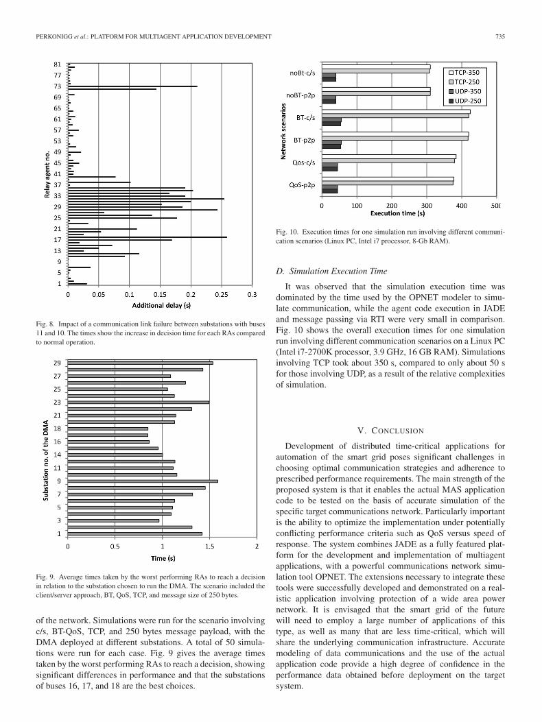
Fig. 8. Impact of a communication link failure between substations with buses11 and 10. The times show the increase in decision time for each RAs comparedto normal operation.
Fig. 9. Average times taken by the worst performing RAs to reach a decisionin relation to the substation chosen to run the DMA. The scenario included theclient/server approach, BT, QoS, TCP, and message size of 250 bytes.
of the network. Simulations were run for the scenario involvingc/s, BT-QoS, TCP, and 250 bytes message payload, with theDMA deployed at different substations. A total of 50 simula-tions were run for each case. Fig. 9 gives the average timestaken by the worst performing RAs to reach a decision, showingsignificant differences in performance and that the substationsof buses 16, 17, and 18 are the best choices.
Fig. 10. Execution times for one simulation run involving different communi-cation scenarios (Linux PC, Intel i7 processor, 8-Gb RAM).
D. Simulation Execution Time
It was observed that the simulation execution time wasdominated by the time used by the OPNET modeler to simu-late communication, while the agent code execution in JADEand message passing via RTI were very small in comparison.Fig. 10 shows the overall execution times for one simulationrun involving different communication scenarios on a Linux PC(Intel i7-2700K processor, 3.9 GHz, 16 GB RAM). Simulationsinvolving TCP took about 350 s, compared to only about 50 sfor those involving UDP, as a result of the relative complexitiesof simulation.
V. CONCLUSION
Development of distributed time-critical applications forautomation of the smart grid poses significant challenges inchoosing optimal communication strategies and adherence toprescribed performance requirements. The main strength of theproposed system is that it enables the actual MAS applicationcode to be tested on the basis of accurate simulation of thespecific target communications network. Particularly importantis the ability to optimize the implementation under potentiallyconflicting performance criteria such as QoS versus speed ofresponse. The system combines JADE as a fully featured plat-form for the development and implementation of multiagentapplications, with a powerful communications network simu-lation tool OPNET. The extensions necessary to integrate thesetools were successfully developed and demonstrated on a real-istic application involving protection of a wide area powernetwork. It is envisaged that the smart grid of the futurewill need to employ a large number of applications of thistype, as well as many that are less time-critical, which willshare the underlying communication infrastructure. Accuratemodeling of data communications and the use of the actualapplication code provide a high degree of confidence in theperformance data obtained before deployment on the targetsystem.

736 IEEE TRANSACTIONS ON INDUSTRIAL INFORMATICS, VOL. 11, NO. 3, JUNE 2015
ACKNOWLEDGMENT
The authors would like to thank the Engineering and PhysicalSciences Research Council for funding this research and theOPNET University Program for providing a free license for theuse of their software.
REFERENCES
[1] V. C. Gungor et al., “Smart grid technologies: Communication tech-nologies and standards,” IEEE Trans. Ind. Informat., vol. 7, no. 4,pp. 529–539, Nov. 2011.
[2] M. Ruofei, C. Hsiao-Hwa, H. Yu-Ren, and M. Weixiao, “Smart grid com-munication: Its challenges and opportunities,” IEEE Trans. Smart Grid,vol. 4, no. 1, pp. 36–46, Mar. 2013.
[3] Q. Yang, J. A. Barria, and T. C. Green, “Communication infrastructuresfor distributed control of power distribution networks,” IEEE Trans. Ind.Informat., vol. 7, no. 2, pp. 316–327, May 2011.
[4] S. D. McArthur et al., “Multi-agent systems for power engineeringapplications—Part I: Concepts, approaches, and technical challenges,”IEEE Trans. Power Syst., vol. 22, no. 4, pp. 1743–1752, Nov. 2007.
[5] S. D. McArthur et al., “Multi-agent systems for power engineeringapplications—Part II: Technologies, standards, and tools for buildingmulti-agent systems,” IEEE Trans. Power Syst., vol. 22, no. 4, pp. 1753–1759, Nov. 2007.
[6] D. V. Coury, J. S. Thorp, K. M. Hopkinson, and K. P. Birman, “An agent-based current differential relay for use with a utility intranet,” IEEE Trans.Power Del., vol. 17, no. 1, pp. 47–53, Jan. 2002.
[7] F. Ren, M. Zhang, D. Soetanto, and X. Su, “Conceptual design of a multi-agent system for interconnected power systems restoration,” IEEE Trans.Power Syst., vol. 27, no. 2, pp. 732–740, May 2012.
[8] H. S. Nwana, D. T. Ndumu, L. C. Lee, and J. C. Collis, “ZEUS: A toolkitand approach for building distributed multi-agent systems,” in Proc. 3rdAnnu. Conf. Auton. Agents, 1999, pp. 360–361.
[9] F. Bellifemine, F. Bergenti, G. Caire, and A. Poggi, “JADE—A java agentdevelopment framework,” in Multi-Agent Programming. New York, NY,USA: Springer, 2005, pp. 125–147.
[10] A. L. Dimeas and N. D. Hatziargyriou, “Operation of a multiagent systemfor microgrid control,” IEEE Trans. Power Syst., vol. 20, no. 3, pp. 1447–1455, Aug. 2005.
[11] H. Wang, “Multi-agent co-ordination for the secondary voltage controlin power-system contingencies,” IEE Proc. Gener. Transmiss. Distrib.,vol. 148, no. 1, pp. 61–66, Jan. 2001.
[12] K. Hopkinson et al., “EPOCHS: A platform for agent-based electricpower and communication simulation built from commercial off-the-shelfcomponents,” IEEE Trans. Power Syst., vol. 21, no. 2, pp. 548–558, May2006.
[13] H. Lin, S. S. Veda, S. S. Shukla, L. Mili, and J. Thorp, “GECO: Globalevent-driven co-simulation framework for interconnected power systemand communication network,” IEEE Trans. Smart Grid, vol. 3, no. 3,pp. 1444–1456, Sep. 2012.
[14] K. Mets, J. Ojea, and C. Develder, “Combining power and communi-cation network simulation for cost-effective smart grid analysis,” IEEECommun. Surv. Tuts., vol. 16, no. 3, pp. 1–26, Aug. 2014.
[15] R. J. Allan, Survey of Agent Based Modelling and Simulation Tools.Swindon, U.K.: Science and Technology Facilities Council, 2010.
[16] F. L. Bellifemine, G. Caire, and D. Greenwood, Developing Multi-AgentSystems With JADE, vol. 7. Hoboken, NJ, USA: Wiley, 2007.
[17] G. Bollella and J. Gosling, “The real-time specification for Java,”Computer, vol. 33, pp. 47–54, 2000.
[18] S. I. S. Committee of the IEEE Computer Society: IEEE Standard forModeling and Simulation (M&S) High Level Architecture (HLA). IEEEStandard 1516-2000, 1516.1-2000, 1516.2-2000, 2000.
[19] S. Straßburger, “On the HLA-based coupling of simulation tools,” inProc. Eur. Simul. Multiconf., 1999, pp. 45–51.
[20] S. Garlapati, H. Lin, S. Sambamoorthy, S. K. Shukla, and J. Thorp,“Agent based supervision of zone 3 relays to prevent hidden failurebased tripping,” in Proc. 1st IEEE Int. Conf. Smart Grid Commun.(SmartGridComm), 2010, pp. 256–261.
[21] IEEE Standard for Modeling and Simulation (M&S) High LevelArchitecture (HLA)–Federate Interface Specification, IEEE Standard15161-2010 (Revision of IEEE Standard 1516.1–2000), 2010, pp. 1–378.
[22] A. Apostolov and B. Vandiver, “IEC 61850 process bus—Principles,applications and benefits,” in Proc. 63rd Annu. Conf. Prot. Relay Eng.,2010, pp. 1–6.
[23] L. Yang, P. A. Crossley, A. Wen, R. Chatfield, and J. Wright, “Design andperformance testing of a multivendor IEC61850–9-2 process bus basedprotection scheme,” IEEE Trans. Smart Grid, vol. 5, no. 3, pp. 1159–1164, May 2014.
[24] A. Buss and L. Jackson, “Distributed simulation modeling: A comparisonof HLA, CORBA, and RMI,” in Proc. 30th Conf. Winter Simul., 1998,pp. 819–826.
[25] E. Shakshuki and Y. Jun, “Multi-agent development toolkits: An evalu-ation,” in Innovations in Applied Artificial Intelligence. New York, NY,USA: Springer, 2004, pp. 209–218.
[26] S. G. Robertz and R. Henriksson, “Time-triggered garbage collection:Robust and adaptive real-time GC scheduling for embedded systems,”in Proc. ACM SIGPLAN Not., 2003, pp. 93–102.
[27] M. H. Dawson, “Challenges in implementing the real-time specifica-tion for Java (RTSJ) in a commercial real-time Java virtual machine,” inProc. 11th IEEE Int. Symp. Object Oriented Real Time Distrib. Comput.(ISORC), 2008, pp. 241–247.
[28] P. M. Anderson, Power System Protection. Piscataway, NJ, USA: IEEEPress, 1999.
Fidelis Perkonigg received the B.S. and M.S. degreesin computer science from the Graz University ofTechnology, Graz, Austria, in 2006, and the Ph.D.degree in mechanical engineering from ImperialCollege London, London, U.K., in 2015.
He worked with Cisco Systems, Vienna, Austria,before his doctoral studies, and he is a CertifiedCisco Routing, Switching, Security, and VoiceProfessional [Cisco Certified Network Professional(CCNP) level]. He is currently a Teaching Fellowwith the Department of Computing, Imperial College
London. His research interests include computer networks, operating systems,and software engineering.
Djordje Brujic (M’95) received the Dipl. Ing. degreein electrical engineering from the University ofBelgrade, Belgrade, Serbia, in 1975; the M.Sc. degreein control systems from the Cranfield University ofTechnology, Bedford, U.K., in 1985; and the Ph.D.degree in geometric modelling from Imperial CollegeLondon, London, U.K., in 2002.
He is a Senior Researcher at Imperial CollegeLondon, whose research interests span real-time con-trol systems, three-dimensional surface reconstruc-tion, and more recently, distributed systems and multi
agent methodologies applied to smart grid problems. He has published over 50papers in these domains.
Mihailo Ristic (M’94) received the degree inmechanical engineering from University CollegeLondon, London, U.K., in 1981, and the M.Sc. degreein control systems and the Ph.D. degree in roboticsfrom Imperial College London, London, in 1982 and1986, respectively.
He is currently a Senior Lecturer in the MechanicalEngineering Department with Imperial CollegeLondon. His research interests include a wide rangeof topics in control systems, computer aided design,electrical machines, as well as magnetic resonance
imaging. He is a Co-Founder of Turbo Power Systems, Gateshead, U.K., whichspecializes in high-speed electric machines and power electronics.
Dr. Ristic is a Chartered Engineer and a Fellow of the Institution ofMechanical Engineers.