platform settings for firepower threat defense...configure banners smartlicense classiclicense...
TRANSCRIPT
Platform Settings for Firepower Threat Defense
Platform settings for FTD devices configure a range of unrelated features whose values you might want toshare among several devices. Even if you want different settings per device, you must create a shared policyand apply it to the desired device.
• Configure ARP Inspection, on page 1• Configure Banners, on page 3• Configure External Authentication for SSH, on page 3• Configure Fragment Handling, on page 7• Configure HTTP, on page 8• Configure ICMP Access Rules, on page 9• Configure SSL Settings , on page 11• Configure Secure Shell, on page 14• Configure SMTP, on page 16• Configure SNMP for Threat Defense, on page 16• Configure Syslog, on page 22• Configure Global Timeouts, on page 35• Configure NTP Time Synchronization for Threat Defense, on page 37• History for Firepower Threat Defense Platform Settings, on page 38
Configure ARP InspectionAccessSupported DomainsSupported DevicesClassic LicenseSmart License
AdminAccess AdminNetwork Admin
AnyFTDN/AAny
By default, all ARP packets are allowed between bridge group members. You can control the flow of ARPpackets by enabling ARP inspection.
ARP inspection prevents malicious users from impersonating other hosts or routers (known as ARP spoofing).ARP spoofing can enable a “man-in-the-middle” attack. For example, a host sends an ARP request to thegateway router; the gateway router responds with the gateway router MAC address. The attacker, however,sends another ARP response to the host with the attacker MAC address instead of the router MAC address.The attacker can now intercept all the host traffic before forwarding it on to the router.
Platform Settings for Firepower Threat Defense1
ARP inspection ensures that an attacker cannot send an ARP response with the attacker MAC address, solong as the correct MAC address and the associated IP address are in the static ARP table.
When you enable ARP inspection, the Firepower Threat Defense device compares the MAC address, IPaddress, and source interface in all ARP packets to static entries in the ARP table, and takes the followingactions:
• If the IP address, MAC address, and source interface match an ARP entry, the packet is passed through.
• If there is a mismatch between the MAC address, the IP address, or the interface, then the FirepowerThreat Defense device drops the packet.
• If the ARP packet does not match any entries in the static ARP table, then you can set the FirepowerThreat Defense device to either forward the packet out all interfaces (flood), or to drop the packet.
The dedicated Diagnostic interface never floods packets even if this parameteris set to flood.
Note
Procedure
Step 1 Select Devices > Platform Settings and create or edit a FTD policy.Step 2 Select ARP Inspection.Step 3 Add entries to the ARP inspection table.
a) Click Add to create a new entry, or click the Edit icon if the entry already exists.b) Select the desired options.
• Inspect Enabled—To perform ARP inspection on the selected interfaces and zones.
• FloodEnabled—Whether to floodARP requests that do not match static ARP entries out all interfacesother than the originating interface or the dedicatedmanagement interface. This is the default behavior.
If you do not elect to flood ARP requests, then only those requests that exactly match static ARPentries are allowed.
• Security Zones—Add the zones that contain the interfaces on which to perform the selected actions.The zones must be switched zones. For interfaces not in a zone, you can type the interface name intothe field below the Selected Security Zone list and clickAdd. These rules will be applied to a deviceonly if the device includes the selected interfaces or zones.
c) Click OK.
Step 4 Add static ARP entries according to Add a Static ARP Entry.Step 5 Click Save.
You can now click Deploy and deploy the policy to assigned devices. The changes are not active until youdeploy them.
Platform Settings for Firepower Threat Defense2
Platform Settings for Firepower Threat DefenseConfigure ARP Inspection
Configure BannersAccessSupported DomainsSupported DevicesClassic LicenseSmart License
AdminAccess AdminNetwork Admin
AnyFTDN/AAny
You can configure messages to show users when they connect to the device command line interface (CLI).
Procedure
Step 1 Select Devices > Platform Settings and create or edit a FTD policy.Step 2 Select Banner.Step 3 Configure the banner.
Following are some tips and requirements for banners.
• Only ASCII characters are allowed. You can use line returns (press Enter), but you cannot use tabs.
• You can dynamically add the hostname or domain name of the device by including the variables$(hostname) or $(domain).
• Although there is no absolute length restriction on banners, Telnet or SSH sessions will close if there isnot enough system memory available to process the banner messages.
• From a security perspective, it is important that your banner discourage unauthorized access. Do not usethe words "welcome" or "please," as they appear to invite intruders in. The following banner sets thecorrect tone for unauthorized access:
You have logged in to a secure device.If you are not authorized to access this device,log out immediately or risk criminal charges.
Step 4 Click Save.
You can now click Deploy and deploy the policy to assigned devices. The changes are not active until youdeploy them.
Configure External Authentication for SSHAccessSupported DomainsSupported DevicesClassic LicenseSmart License
AdministratorAnyFTDN/AAny
Platform Settings for Firepower Threat Defense3
Platform Settings for Firepower Threat DefenseConfigure Banners
When you enable external authentication for management users, the FTD verifies the user credentials withan LDAP or RADIUS server as specified in an external authentication object.
Sharing External Authentication Objects
External authentication objects can be used by the FMC, 7000 and 8000 Series, and FTD devices. You canshare the same object between all 3 types, or create separate objects.
Assigning External Authentication Objects to Devices
For the FMC, enable the external authentication objects directly on the System > Users > ExternalAuthentication tab; this setting only affects FMC usage, and it does not need to be enabled on this tab formanaged device usage. For 7000 and 8000 Series and FTD devices, youmust enable the external authenticationobject in the platform settings that you deploy to the devices. For the FTD, you can only activate one externalauthentication object per policy. An LDAP object with CAC authentication enabled cannot also be used forCLI access.
FTD Supported Fields
Only a subset of fields in the external authentication object are used for FTD SSH access. If you fill in additionalfields, they are ignored. If you also use this object for other device types, those fields will be used. Thisprocedure only covers the supported fields for the FTD. For other fields, see Configure External Authentication.
Usernames
Usernamesmust be Linux-valid usernames and be lower-case only, using alphanumeric characters plus period(.) or hyphen (-). Other special characters such as at sign (@) and slash (/) are not supported. You cannot addthe admin user for external authentication. You can only add external users (as part of the ExternalAuthentication object) in the FMC; you cannot add them at the CLI. Note that internal users can only be addedat the CLI, not in the FMC.
If you previously configured the same username for an internal user using the configure user add command,the FTD first checks the password against the internal user, and if that fails, it checks the AAA server. Notethat you cannot later add an internal user with the same name as an external user; only pre-existing internalusers are supported.
Privilege Level
External users always have Config privileges; other user roles are not supported.
Before you begin
• SSH access is enabled by default on the management interface. To enable SSH access on data interfaces,see Configure Secure Shell, on page 14. SSH is not supported to the Diagnostic interface.
• Please inform RADIUS users of the following behavior to set their expectations appropriately:
• The first time an external user logs in, FTD creates the required structures but cannot simultaneouslycreate the user session. The user simply needs to authenticate again to start the session. The userwill see a message similar to the following: "New external username identified. Please log in againto start a session."
• Similarly, if the user’s authorization as defined in the Service-Type changed since the last login,the user will need to re-authenticate. The user will see a message similar to the following: "Yourauthorization privilege has changed. Please log in again to start a session."
Platform Settings for Firepower Threat Defense4
Platform Settings for Firepower Threat DefenseConfigure External Authentication for SSH
Procedure
Step 1 Select Devices > Platform Settings and create or edit a FTD policy.Step 2 Click External Authentication.Step 3 Click theManage External Authentication Server link.
The System > Users > External Authentication screen opens in a new browser tab.
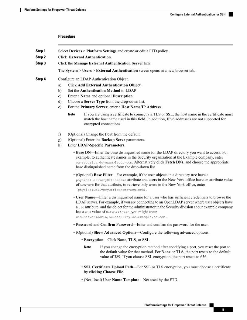
Step 4 Configure an LDAP Authentication Object.a) Click Add External Authentication Object.b) Set the Authentication Method to LDAPc) Enter a Name and optional Description.d) Choose a Server Type from the drop-down list.e) For the Primary Server, enter a Host Name/IP Address.
If you are using a certificate to connect via TLS or SSL, the host name in the certificate mustmatch the host name used in this field. In addition, IPv6 addresses are not supported forencrypted connections.
Note
f) (Optional) Change the Port from the default.g) (Optional) Enter the Backup Sever parameters.h) Enter LDAP-Specific Parameters.
• Base DN—Enter the base distinguished name for the LDAP directory you want to access. Forexample, to authenticate names in the Security organization at the Example company, enterou=security,dc=example,dc=com. Alternatively click Fetch DNs, and choose the appropriatebase distinguished name from the drop-down list.
• (Optional) Base Filter—For example, if the user objects in a directory tree have aphysicalDeliveryOfficeName attribute and users in the New York office have an attribute valueof NewYork for that attribute, to retrieve only users in the New York office, enter(physicalDeliveryOfficeName=NewYork).
• User Name—Enter a distinguished name for a user who has sufficient credentials to browse theLDAP server. For example, if you are connecting to an OpenLDAP server where user objects havea uid attribute, and the object for the administrator in the Security division at our example companyhas a uid value of NetworkAdmin, you might enteruid=NetworkAdmin,ou=security,dc=example,dc=com.
• Password and Confirm Password—Enter and confirm the password for the user.
• (Optional) Show Advanced Options—Configure the following advanced options.
• Encryption—Click None, TLS, or SSL.
If you change the encryption method after specifying a port, you reset the port tothe default value for that method. For None or TLS, the port resets to the defaultvalue of 389. If you choose SSL encryption, the port resets to 636.
Note
• SSL Certificate Upload Path—For SSL or TLS encryption, you must choose a certificateby clicking Choose File.
• (Not Used) User Name Template—Not used by the FTD.
Platform Settings for Firepower Threat Defense5
Platform Settings for Firepower Threat DefenseConfigure External Authentication for SSH
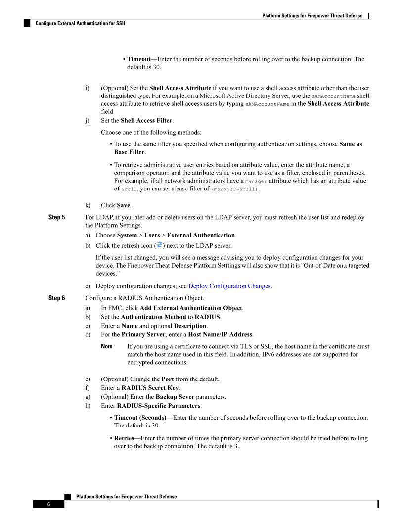
• Timeout—Enter the number of seconds before rolling over to the backup connection. Thedefault is 30.
i) (Optional) Set the Shell Access Attribute if you want to use a shell access attribute other than the userdistinguished type. For example, on a Microsoft Active Directory Server, use the sAMAccountName shellaccess attribute to retrieve shell access users by typing sAMAccountName in the Shell Access Attributefield.
j) Set the Shell Access Filter.
Choose one of the following methods:
• To use the same filter you specified when configuring authentication settings, choose Same asBase Filter.
• To retrieve administrative user entries based on attribute value, enter the attribute name, acomparison operator, and the attribute value you want to use as a filter, enclosed in parentheses.For example, if all network administrators have a manager attribute which has an attribute valueof shell, you can set a base filter of (manager=shell).
k) Click Save.
Step 5 For LDAP, if you later add or delete users on the LDAP server, you must refresh the user list and redeploythe Platform Settings.a) Choose System > Users > External Authentication.b) Click the refresh icon ( ) next to the LDAP server.
If the user list changed, you will see a message advising you to deploy configuration changes for yourdevice. The Firepower Theat Defense Platform Setttings will also show that it is "Out-of-Date on x targeteddevices."
c) Deploy configuration changes; see Deploy Configuration Changes.
Step 6 Configure a RADIUS Authentication Object.a) In FMC, click Add External Authentication Object.b) Set the Authentication Method to RADIUS.c) Enter a Name and optional Description.d) For the Primary Server, enter a Host Name/IP Address.
If you are using a certificate to connect via TLS or SSL, the host name in the certificate mustmatch the host name used in this field. In addition, IPv6 addresses are not supported forencrypted connections.
Note
e) (Optional) Change the Port from the default.f) Enter a RADIUS Secret Key.g) (Optional) Enter the Backup Sever parameters.h) Enter RADIUS-Specific Parameters.
• Timeout (Seconds)—Enter the number of seconds before rolling over to the backup connection.The default is 30.
• Retries—Enter the number of times the primary server connection should be tried before rollingover to the backup connection. The default is 3.
Platform Settings for Firepower Threat Defense6
Platform Settings for Firepower Threat DefenseConfigure External Authentication for SSH
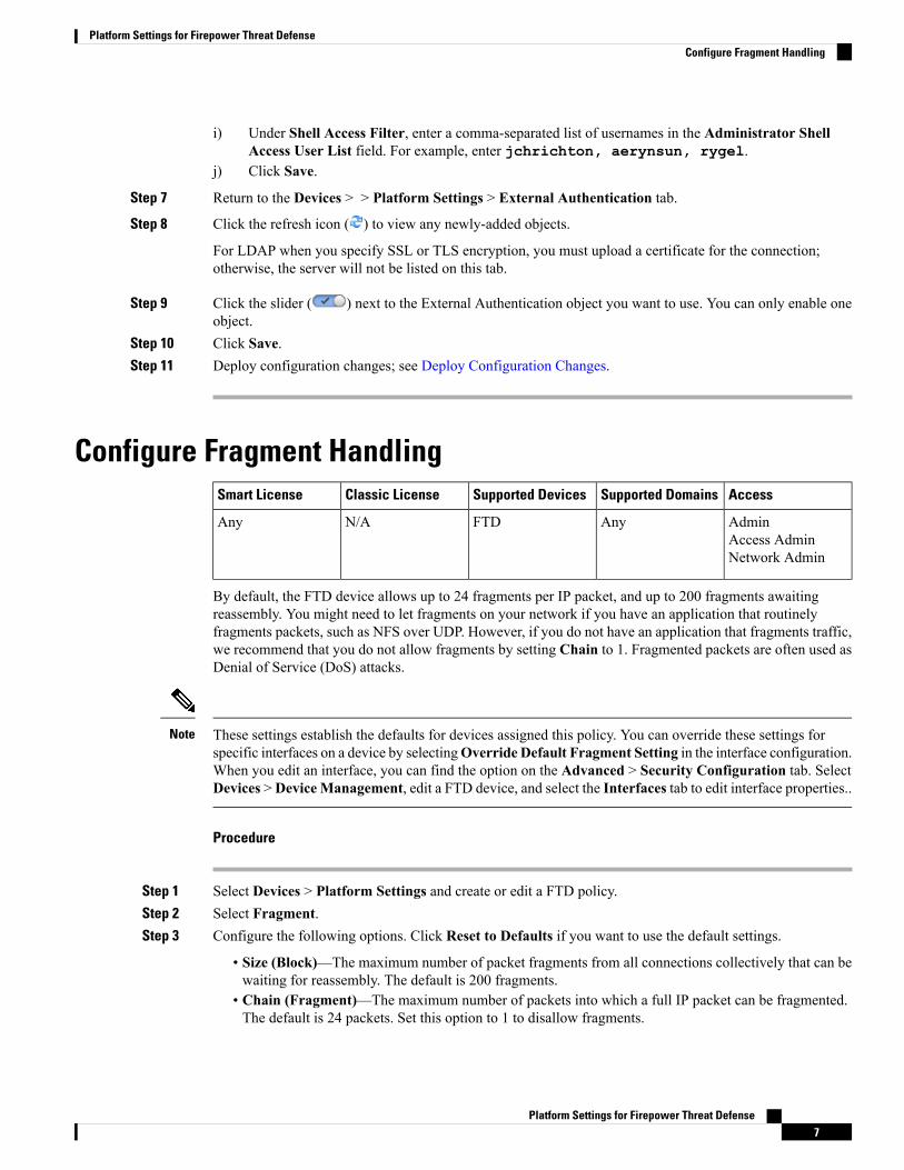
i) Under Shell Access Filter, enter a comma-separated list of usernames in the Administrator ShellAccess User List field. For example, enter jchrichton, aerynsun, rygel.
j) Click Save.
Step 7 Return to the Devices > > Platform Settings > External Authentication tab.
Step 8 Click the refresh icon ( ) to view any newly-added objects.
For LDAP when you specify SSL or TLS encryption, you must upload a certificate for the connection;otherwise, the server will not be listed on this tab.
Step 9 Click the slider ( ) next to the External Authentication object you want to use. You can only enable oneobject.
Step 10 Click Save.Step 11 Deploy configuration changes; see Deploy Configuration Changes.
Configure Fragment HandlingAccessSupported DomainsSupported DevicesClassic LicenseSmart License
AdminAccess AdminNetwork Admin
AnyFTDN/AAny
By default, the FTD device allows up to 24 fragments per IP packet, and up to 200 fragments awaitingreassembly. You might need to let fragments on your network if you have an application that routinelyfragments packets, such as NFS over UDP. However, if you do not have an application that fragments traffic,we recommend that you do not allow fragments by setting Chain to 1. Fragmented packets are often used asDenial of Service (DoS) attacks.
These settings establish the defaults for devices assigned this policy. You can override these settings forspecific interfaces on a device by selectingOverride Default Fragment Setting in the interface configuration.When you edit an interface, you can find the option on the Advanced > Security Configuration tab. SelectDevices >DeviceManagement, edit a FTD device, and select the Interfaces tab to edit interface properties..
Note
Procedure
Step 1 Select Devices > Platform Settings and create or edit a FTD policy.Step 2 Select Fragment.Step 3 Configure the following options. Click Reset to Defaults if you want to use the default settings.
• Size (Block)—The maximum number of packet fragments from all connections collectively that can bewaiting for reassembly. The default is 200 fragments.
• Chain (Fragment)—The maximum number of packets into which a full IP packet can be fragmented.The default is 24 packets. Set this option to 1 to disallow fragments.
Platform Settings for Firepower Threat Defense7
Platform Settings for Firepower Threat DefenseConfigure Fragment Handling
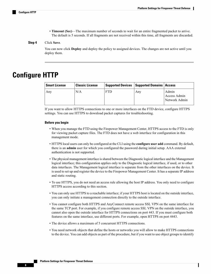
• Timeout (Sec)—The maximum number of seconds to wait for an entire fragmented packet to arrive.The default is 5 seconds. If all fragments are not received within this time, all fragments are discarded.
Step 4 Click Save.
You can now click Deploy and deploy the policy to assigned devices. The changes are not active until youdeploy them.
Configure HTTPAccessSupported DomainsSupported DevicesClassic LicenseSmart License
AdminAccess AdminNetwork Admin
AnyFTDN/AAny
If you want to allow HTTPS connections to one or more interfaces on the FTD device, configure HTTPSsettings. You can use HTTPS to download packet captures for troubleshooting.
Before you begin
• When you manage the FTD using the Firepower Management Center, HTTPS access to the FTD is onlyfor viewing packet capture files. The FTD does not have a web interface for configuration in thismanagement mode.
• HTTPS local users can only be configured at the CLI using the configure user add command. By default,there is an admin user for which you configured the password during initial setup. AAA externalauthentication is not supported.
• The physical management interface is shared between the Diagnostic logical interface and theManagementlogical interface; this configuration applies only to the Diagnostic logical interface, if used, or to otherdata interfaces. The Management logical interface is separate from the other interfaces on the device. Itis used to set up and register the device to the FirepowerManagement Center. It has a separate IP addressand static routing.
• To use HTTPS, you do not need an access rule allowing the host IP address. You only need to configureHTTPS access according to this section.
• You can only use HTTPS to a reachable interface; if your HTTPS host is located on the outside interface,you can only initiate a management connection directly to the outside interface.
• You cannot configure both HTTPS and AnyConnect remote access SSL VPN on the same interface forthe same TCP port. For example, if you configure remote access SSL VPN on the outside interface, youcannot also open the outside interface for HTTPS connections on port 443. If you must configure bothfeatures on the same interface, use different ports. For example, open HTTPS on port 4443.
• The device allows a maximum of 5 concurrent HTTPS connections.
• You need network objects that define the hosts or networks you will allow to make HTTPS connectionsto the device. You can add objects as part of the procedure, but if you want to use object groups to identify
Platform Settings for Firepower Threat Defense8
Platform Settings for Firepower Threat DefenseConfigure HTTP
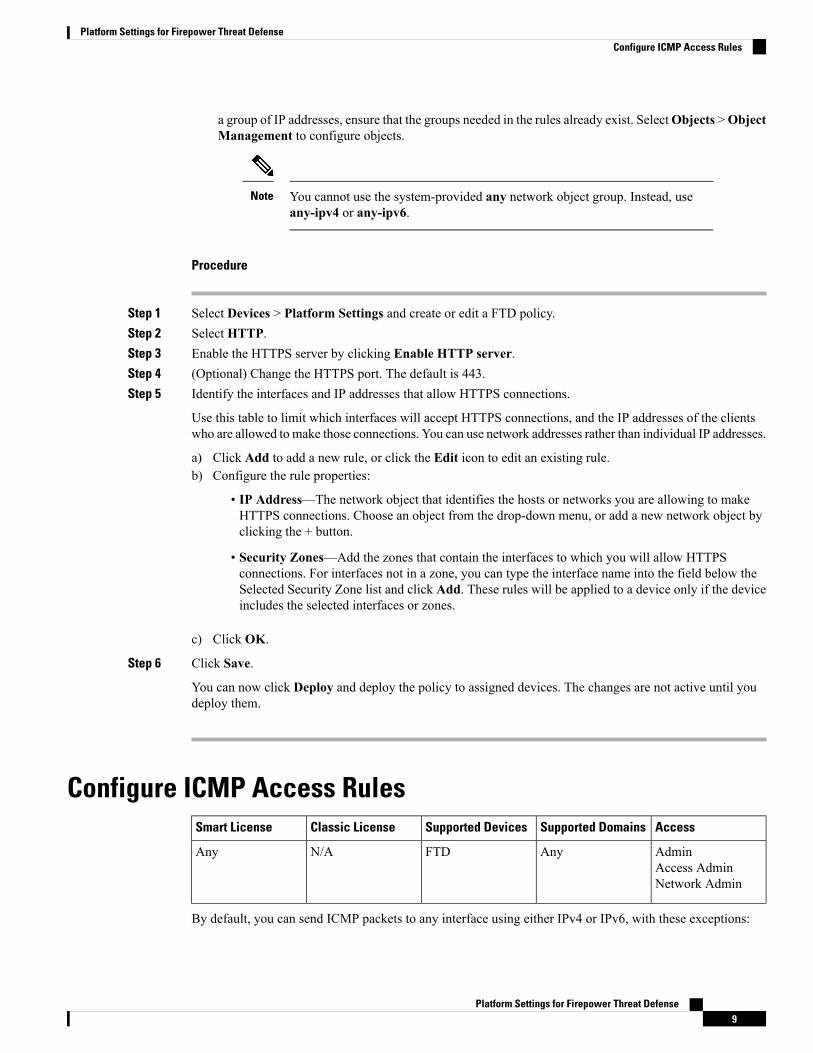
a group of IP addresses, ensure that the groups needed in the rules already exist. SelectObjects >ObjectManagement to configure objects.
You cannot use the system-provided any network object group. Instead, useany-ipv4 or any-ipv6.
Note
Procedure
Step 1 Select Devices > Platform Settings and create or edit a FTD policy.Step 2 Select HTTP.Step 3 Enable the HTTPS server by clicking Enable HTTP server.Step 4 (Optional) Change the HTTPS port. The default is 443.Step 5 Identify the interfaces and IP addresses that allow HTTPS connections.
Use this table to limit which interfaces will accept HTTPS connections, and the IP addresses of the clientswho are allowed to make those connections. You can use network addresses rather than individual IP addresses.
a) Click Add to add a new rule, or click the Edit icon to edit an existing rule.b) Configure the rule properties:
• IP Address—The network object that identifies the hosts or networks you are allowing to makeHTTPS connections. Choose an object from the drop-down menu, or add a new network object byclicking the + button.
• Security Zones—Add the zones that contain the interfaces to which you will allow HTTPSconnections. For interfaces not in a zone, you can type the interface name into the field below theSelected Security Zone list and click Add. These rules will be applied to a device only if the deviceincludes the selected interfaces or zones.
c) Click OK.
Step 6 Click Save.
You can now click Deploy and deploy the policy to assigned devices. The changes are not active until youdeploy them.
Configure ICMP Access RulesAccessSupported DomainsSupported DevicesClassic LicenseSmart License
AdminAccess AdminNetwork Admin
AnyFTDN/AAny
By default, you can send ICMP packets to any interface using either IPv4 or IPv6, with these exceptions:
Platform Settings for Firepower Threat Defense9
Platform Settings for Firepower Threat DefenseConfigure ICMP Access Rules
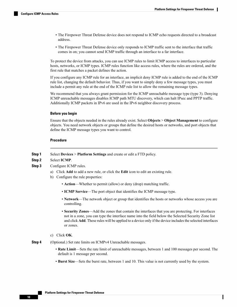
• The Firepower Threat Defense device does not respond to ICMP echo requests directed to a broadcastaddress.
• The Firepower Threat Defense device only responds to ICMP traffic sent to the interface that trafficcomes in on; you cannot send ICMP traffic through an interface to a far interface.
To protect the device from attacks, you can use ICMP rules to limit ICMP access to interfaces to particularhosts, networks, or ICMP types. ICMP rules function like access rules, where the rules are ordered, and thefirst rule that matches a packet defines the action.
If you configure any ICMP rule for an interface, an implicit deny ICMP rule is added to the end of the ICMPrule list, changing the default behavior. Thus, if you want to simply deny a few message types, you mustinclude a permit any rule at the end of the ICMP rule list to allow the remaining message types.
We recommend that you always grant permission for the ICMP unreachable message type (type 3). DenyingICMP unreachable messages disables ICMP path MTU discovery, which can halt IPsec and PPTP traffic.Additionally ICMP packets in IPv6 are used in the IPv6 neighbor discovery process.
Before you begin
Ensure that the objects needed in the rules already exist. SelectObjects >Object Management to configureobjects. You need network objects or groups that define the desired hosts or networks, and port objects thatdefine the ICMP message types you want to control.
Procedure
Step 1 Select Devices > Platform Settings and create or edit a FTD policy.Step 2 Select ICMP.Step 3 Configure ICMP rules.
a) Click Add to add a new rule, or click the Edit icon to edit an existing rule.b) Configure the rule properties:
• Action—Whether to permit (allow) or deny (drop) matching traffic.
• ICMP Service—The port object that identifies the ICMP message type.
• Network—The network object or group that identifies the hosts or networks whose access you arecontrolling.
• Security Zones—Add the zones that contain the interfaces that you are protecting. For interfacesnot in a zone, you can type the interface name into the field below the Selected Security Zone listand clickAdd. These rules will be applied to a device only if the device includes the selected interfacesor zones.
c) Click OK.
Step 4 (Optional.) Set rate limits on ICMPv4 Unreachable messages.
• Rate Limit—Sets the rate limit of unreachable messages, between 1 and 100 messages per second. Thedefault is 1 message per second.
• Burst Size—Sets the burst rate, between 1 and 10. This value is not currently used by the system.
Platform Settings for Firepower Threat Defense10
Platform Settings for Firepower Threat DefenseConfigure ICMP Access Rules
Step 5 Click Save.
You can now click Deploy and deploy the policy to assigned devices. The changes are not active until youdeploy them.
Configure SSL SettingsAccessSupported DomainsSupported DevicesClassic LicenseSmart License
AdminLeaf onlyFTDN/AExport-Compliance
Before you begin
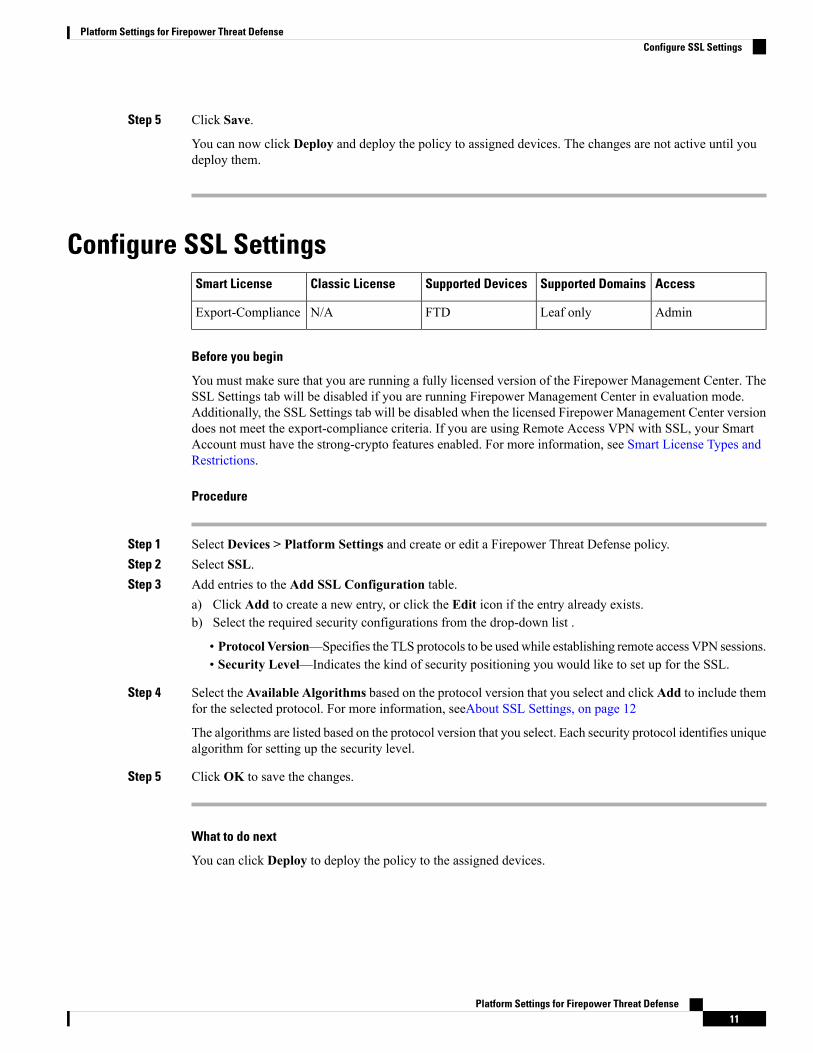
You must make sure that you are running a fully licensed version of the Firepower Management Center. TheSSL Settings tab will be disabled if you are running Firepower Management Center in evaluation mode.Additionally, the SSL Settings tab will be disabled when the licensed Firepower Management Center versiondoes not meet the export-compliance criteria. If you are using Remote Access VPN with SSL, your SmartAccount must have the strong-crypto features enabled. For more information, see Smart License Types andRestrictions.
Procedure
Step 1 Select Devices > Platform Settings and create or edit a Firepower Threat Defense policy.Step 2 Select SSL.Step 3 Add entries to the Add SSL Configuration table.
a) Click Add to create a new entry, or click the Edit icon if the entry already exists.b) Select the required security configurations from the drop-down list .
• Protocol Version—Specifies the TLS protocols to be used while establishing remote access VPN sessions.• Security Level—Indicates the kind of security positioning you would like to set up for the SSL.
Step 4 Select the Available Algorithms based on the protocol version that you select and click Add to include themfor the selected protocol. For more information, seeAbout SSL Settings, on page 12
The algorithms are listed based on the protocol version that you select. Each security protocol identifies uniquealgorithm for setting up the security level.
Step 5 Click OK to save the changes.
What to do next
You can click Deploy to deploy the policy to the assigned devices.
Platform Settings for Firepower Threat Defense11
Platform Settings for Firepower Threat DefenseConfigure SSL Settings
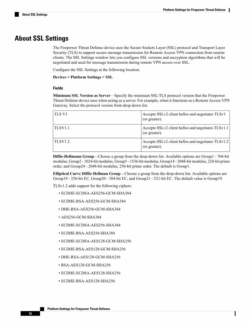
About SSL SettingsThe Firepower Threat Defense device uses the Secure Sockets Layer (SSL) protocol and Transport LayerSecurity (TLS) to support secure message transmission for Remote Access VPN connection from remoteclients. The SSL Settings window lets you configure SSL versions and encryption algorithms that will benegotiated and used for message transmission during remote VPN access over SSL.
Configure the SSL Settings at the following location:
Devices > Platform Settings > SSL
Fields
Minimum SSL Version as Server—Specify the minimum SSL/TLS protocol version that the FirepowerThreat Defense device uses when acting as a server. For example, when it functions as a Remote Access VPNGateway. Select the protocol version from drop-down list.
Accepts SSLv2 client hellos and negotiates TLSv1(or greater).
TLS V1
Accepts SSLv2 client hellos and negotiates TLSv1.1(or greater).
TLSV1.1
Accepts SSLv2 client hellos and negotiates TLSv1.2(or greater).
TLSV1.2
Diffie-Hellmann Group—Choose a group from the drop-down list. Available options are Group1 - 768-bitmodulus, Group2 - 1024-bit modulus, Group5 - 1536-bit modulus, Group14 - 2048-bit modulus, 224-bit primeorder, and Group24 - 2048-bit modulus, 256-bit prime order. The default is Group1.
Elliptical Curve Diffie-Hellman Group—Choose a group from the drop-down list. Available options areGroup19 - 256-bit EC, Group20 - 384-bit EC, and Group21 - 521-bit EC. The default value is Group19.
TLSv1.2 adds support for the following ciphers:
• ECDHE-ECDSA-AES256-GCM-SHA384
• ECDHE-RSA-AES256-GCM-SHA384
• DHE-RSA-AES256-GCM-SHA384
• AES256-GCM-SHA384
• ECDHE-ECDSA-AES256-SHA384
• ECDHE-RSA-AES256-SHA384
• ECDHE-ECDSA-AES128-GCM-SHA256
• ECDHE-RSA-AES128-GCM-SHA256
• DHE-RSA-AES128-GCM-SHA256
• RSA-AES128-GCM-SHA256
• ECDHE-ECDSA-AES128-SHA256
• ECDHE-RSA-AES128-SHA256
Platform Settings for Firepower Threat Defense12
Platform Settings for Firepower Threat DefenseAbout SSL Settings
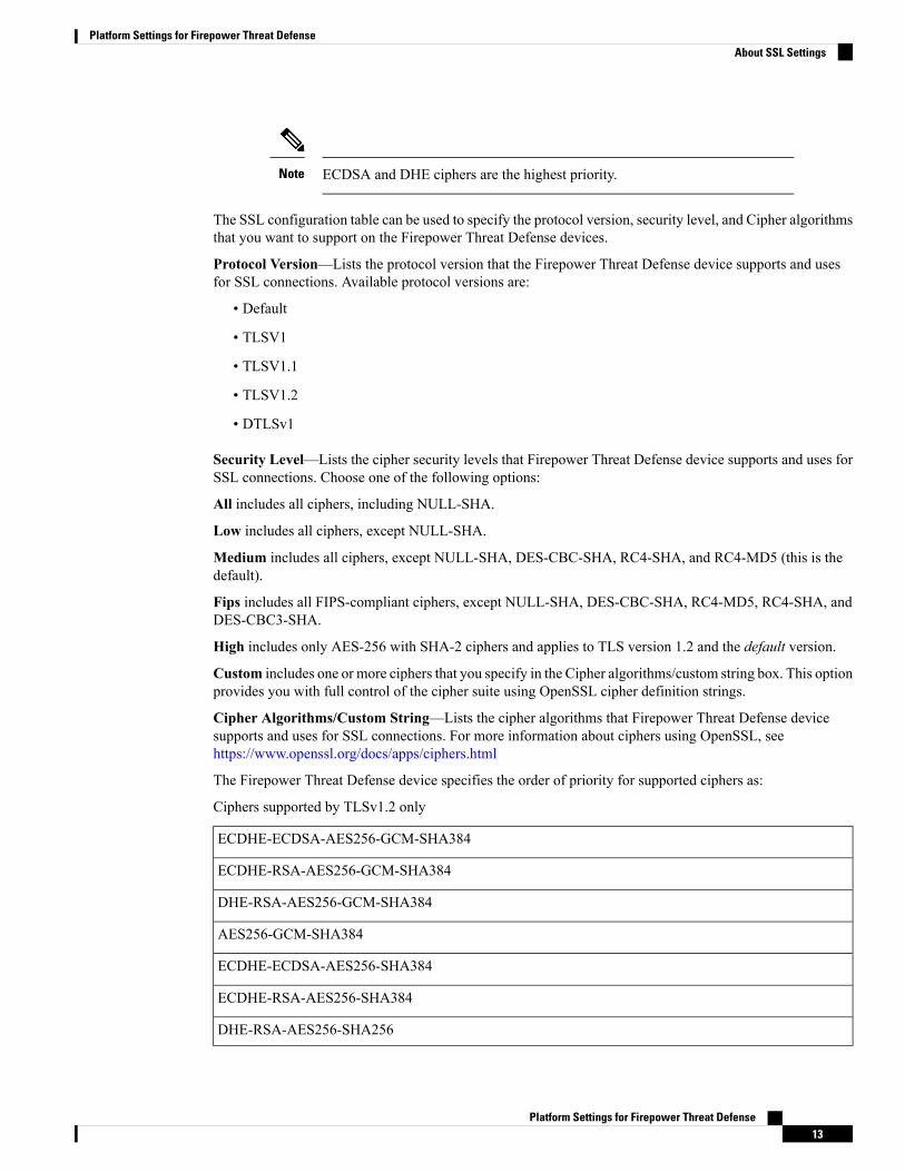
ECDSA and DHE ciphers are the highest priority.Note
The SSL configuration table can be used to specify the protocol version, security level, and Cipher algorithmsthat you want to support on the Firepower Threat Defense devices.
Protocol Version—Lists the protocol version that the Firepower Threat Defense device supports and usesfor SSL connections. Available protocol versions are:
• Default
• TLSV1
• TLSV1.1
• TLSV1.2
• DTLSv1
Security Level—Lists the cipher security levels that Firepower Threat Defense device supports and uses forSSL connections. Choose one of the following options:
All includes all ciphers, including NULL-SHA.
Low includes all ciphers, except NULL-SHA.
Medium includes all ciphers, except NULL-SHA, DES-CBC-SHA, RC4-SHA, and RC4-MD5 (this is thedefault).
Fips includes all FIPS-compliant ciphers, except NULL-SHA, DES-CBC-SHA, RC4-MD5, RC4-SHA, andDES-CBC3-SHA.
High includes only AES-256 with SHA-2 ciphers and applies to TLS version 1.2 and the default version.
Custom includes one or more ciphers that you specify in the Cipher algorithms/custom string box. This optionprovides you with full control of the cipher suite using OpenSSL cipher definition strings.
Cipher Algorithms/Custom String—Lists the cipher algorithms that Firepower Threat Defense devicesupports and uses for SSL connections. For more information about ciphers using OpenSSL, seehttps://www.openssl.org/docs/apps/ciphers.html
The Firepower Threat Defense device specifies the order of priority for supported ciphers as:
Ciphers supported by TLSv1.2 only
ECDHE-ECDSA-AES256-GCM-SHA384
ECDHE-RSA-AES256-GCM-SHA384
DHE-RSA-AES256-GCM-SHA384
AES256-GCM-SHA384
ECDHE-ECDSA-AES256-SHA384
ECDHE-RSA-AES256-SHA384
DHE-RSA-AES256-SHA256
Platform Settings for Firepower Threat Defense13
Platform Settings for Firepower Threat DefenseAbout SSL Settings
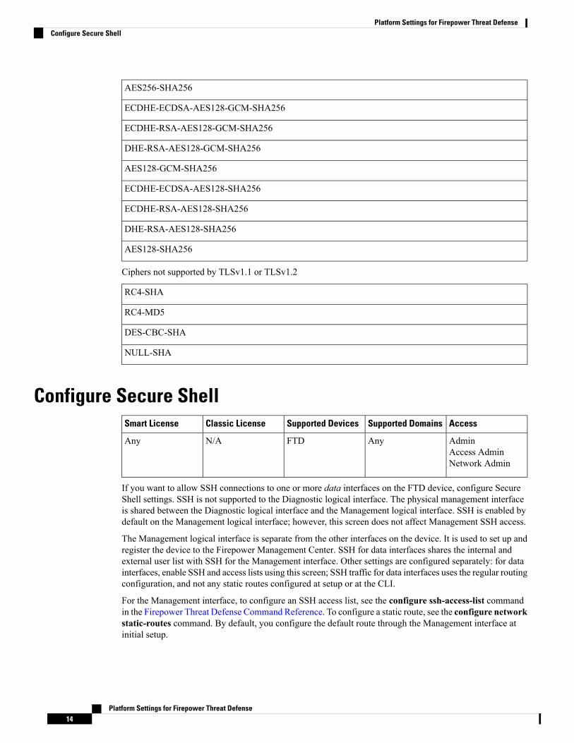
AES256-SHA256
ECDHE-ECDSA-AES128-GCM-SHA256
ECDHE-RSA-AES128-GCM-SHA256
DHE-RSA-AES128-GCM-SHA256
AES128-GCM-SHA256
ECDHE-ECDSA-AES128-SHA256
ECDHE-RSA-AES128-SHA256
DHE-RSA-AES128-SHA256
AES128-SHA256
Ciphers not supported by TLSv1.1 or TLSv1.2
RC4-SHA
RC4-MD5
DES-CBC-SHA
NULL-SHA
Configure Secure ShellAccessSupported DomainsSupported DevicesClassic LicenseSmart License
AdminAccess AdminNetwork Admin
AnyFTDN/AAny
If you want to allow SSH connections to one or more data interfaces on the FTD device, configure SecureShell settings. SSH is not supported to the Diagnostic logical interface. The physical management interfaceis shared between the Diagnostic logical interface and the Management logical interface. SSH is enabled bydefault on the Management logical interface; however, this screen does not affect Management SSH access.
The Management logical interface is separate from the other interfaces on the device. It is used to set up andregister the device to the Firepower Management Center. SSH for data interfaces shares the internal andexternal user list with SSH for the Management interface. Other settings are configured separately: for datainterfaces, enable SSH and access lists using this screen; SSH traffic for data interfaces uses the regular routingconfiguration, and not any static routes configured at setup or at the CLI.
For the Management interface, to configure an SSH access list, see the configure ssh-access-list commandin the Firepower Threat Defense Command Reference. To configure a static route, see the configure networkstatic-routes command. By default, you configure the default route through the Management interface atinitial setup.
Platform Settings for Firepower Threat Defense14
Platform Settings for Firepower Threat DefenseConfigure Secure Shell
To use SSH, you do not also need an access rule allowing the host IP address. You only need to configureSSH access according to this section.
You can only SSH to a reachable interface; if your SSH host is located on the outside interface, you can onlyinitiate a management connection directly to the outside interface.
The device allows a maximum of 5 concurrent SSH connections.
Before you begin
• You can configure SSH internal users at the CLI using the configure user add command; see Add anInternal User at the CLI. By default, there is an admin user for which you configured the password duringinitial setup. You can also configure external users on LDAP or RADIUS by configuring ExternalAuthentication in platform settings. See Configure External Authentication for SSH, on page 3.
• You need network objects that define the hosts or networks you will allow to make SSH connections tothe device. You can add objects as part of the procedure, but if you want to use object groups to identifya group of IP addresses, ensure that the groups needed in the rules already exist. SelectObjects >ObjectManagement to configure objects.
You cannot use the system-provided any network object. Instead, use any-ipv4or any-ipv6.
Note
Procedure
Step 1 Select Devices > Platform Settings and create or edit a FTD policy.Step 2 Select Secure Shell.Step 3 Identify the interfaces and IP addresses that allow SSH connections.
Use this table to limit which interfaces will accept SSH connections, and the IP addresses of the clients whoare allowed to make those connections. You can use network addresses rather than individual IP addresses.
a) Click Add to add a new rule, or click the Edit icon to edit an existing rule.b) Configure the rule properties:
• IP Address—The network object that identifies the hosts or networks you are allowing to make SSHconnections. Choose an object from the drop-down menu, or add a new network object by clickingthe + button.
• Security Zones—Add the zones that contain the interfaces to which you will allow SSH connections.For interfaces not in a zone, you can type the interface name into the field below the Selected SecurityZone list and clickAdd. These rules will be applied to a device only if the device includes the selectedinterfaces or zones.
c) Click OK.
Step 4 Click Save.
Platform Settings for Firepower Threat Defense15
Platform Settings for Firepower Threat DefenseConfigure Secure Shell
You can now click Deploy and deploy the policy to assigned devices. The changes are not active until youdeploy them.
Configure SMTPAccessSupported DomainsSupported DevicesClassic LicenseSmart License
AdminAccess AdminNetwork Admin
AnyFTDN/AAny
You must identity an SMTP server if you configure email alerts in the Syslog settings. The source emailaddress you configure for Syslog must be a valid account on the SMTP servers.
Before you begin
Ensure that the network objects that define the host address of the primary and secondary SMTP servers exist.Select Objects > Object Management to define the objects. Alternatively, you can create the objects whileediting the policy.
Procedure
Step 1 Select Devices > Platform Settings and create or edit a FTD policy.Step 2 Click SMTP Server.Step 3 Select the network objects that identify the Primary Server IP Address and optionally, the Secondary Server
IP Address.Step 4 Click Save.
You can now click Deploy and deploy the policy to assigned devices. The changes are not active until youdeploy them.
Configure SNMP for Threat DefenseAccessSupported DomainsSupported DevicesClassic LicenseSmart License
AdminAccess AdminNetwork Admin
AnyFTDN/AAny
Simple Network Management Protocol (SNMP) defines a standard way for network management stationsrunning on PCs or workstations to monitor the health and status of many types of devices, including switches,routers, and security appliances. You can use the SNMP page to configure a firewall device for monitoringby SNMP management stations.
Platform Settings for Firepower Threat Defense16
Platform Settings for Firepower Threat DefenseConfigure SMTP
The Simple Network Management Protocol (SNMP) enables monitoring of network devices from a centrallocation. Cisco security appliances support network monitoring using SNMP versions 1, 2c, and 3, as well astraps and SNMP read access; SNMP write access is not supported.
SNMPv3 only supports read-only users and encryption with AES128.
To create an alert to an external SNMP server, access Policies > Action > AlertsNote
Procedure
Step 1 Select Devices > Platform Settings and create or edit a FTD policy.Step 2 Select SNMP.Step 3 Enable SNMP and configure basic options.
• Enable SNMP Servers—Whether to provide SNMP information to the configured SNMP hosts. Youcan deselect this option to disable SNMP monitoring while retaining the configuration information.
• Read Community String, Confirm—Enter the password used by a SNMP management station whensending requests to the FTD device. The SNMP community string is a shared secret among the SNMPmanagement stations and the network nodes being managed. The security device uses the password todetermine if the incoming SNMP request is valid. The password is a case-sensitive alphanumeric stringof up to 32 characters; spaces are not permitted.
• SystemAdministrator Name—Enter the name of the device administrator or other contact person. Thisstring is case-sensitive and can be up to 127 characters. Spaces are accepted, but multiple spaces areshortened to a single space.
• Location—Enter the location of this security device (for example, Building 42,Sector 54). This stringis case-sensitive and can be up to 127 characters. Spaces are accepted, but multiple spaces are shortenedto a single space.
• Port—Enter the UDP port on which incoming requests will be accepted. The default is 161.
Step 4 (SNMPv3 only.) Add SNMPv3 Users, on page 17.Step 5 Add SNMP Hosts, on page 19.Step 6 Configure SNMP Traps, on page 20.Step 7 Click Save.
You can now click Deploy and deploy the policy to assigned devices. The changes are not active until youdeploy them.
Add SNMPv3 Users
You create users for SNMPv3 only. These steps are not applicable for SNMPv1 or SNMPv2c.Note
Note that SNMPv3 only supports read-only users.
Platform Settings for Firepower Threat Defense17
Platform Settings for Firepower Threat DefenseAdd SNMPv3 Users
SNMP users have a specified username, an authentication password, an encryption password, and authenticationand encryption algorithms to use. The authentication algorithm options are MD5 and SHA. The encryptionalgorithm options are DES, 3DES, and AES128.
Procedure
Step 1 Select Devices > Platform Settings and create or edit a FTD policy.Step 2 Click SNMP from the table of contents and then click the Users tab.Step 3 Click Add.Step 4 Select the security level for the user from the Security Level drop-down list.
• Auth—Authentication but No Privacy, which means that messages are authenticated.
• No Auth—No Authentication and No Privacy, which means that no security is applied to messages.
• Priv—Authentication and Privacy, which means that messages are authenticated and encrypted.
Step 5 Enter the name of the SNMP user in the Username field. Usernames must be 32 characters or less.Step 6 Select the type of password, you want to use in the Encryption Password Type drop-down list.
• Clear text—The FTD device will still encrypt the password when deploying to the device.• Encrypted—The FTD device will directly deploy the encrypted password.
Step 7 Select the type of authentication you want to use: MD5 or SHA, in the Auth Algorithm Type drop-downlist.
Step 8 In theAuthentication Password field, enter the password to use for authentication. If you selected Encryptedas the Encrypt Password Type, the password must be formatted as xx:xx:xx..., where xx are hexadecimalvalues.
The length of the password will depend on the authentication algorithm selected. For all passwords,the length must be 256 characters or less.
Note
If you selected Clear Text as the Encrypt Password Type, repeat the password in the Confirm field.
Step 9 In the Encryption Type drop-down list, select the type of encryption you want to use: AES128,AES192,AES256, 3DES, DES.
To use AES or 3DES encryption, you must have the appropriate license installed on the device.Note
Step 10 Enter the password to use for encryption in theEncryption Password field. If you selected Encrypted as theEncrypt Password Type, the password must be formatted as xx:xx:xx..., where xx are hexadecimal values.For encrypted passwords, the length of the password depends on the encryption type selected. The passwordsizes are as follows (where each xx is one octal):
• AES 128 requires 16 octals
• AES 192 requires 24 octals
• AES 256 requires 32 octals
• 3DES requires 32 octals
• DES can be any size
Platform Settings for Firepower Threat Defense18
Platform Settings for Firepower Threat DefenseAdd SNMPv3 Users
For all passwords, the length must be 256 characters or less.Note
If you selected Clear Text as the Encrypt Password Type, repeat the password in the Confirm field.
Step 11 Click OK.Step 12 Click Save.
You can now click Deploy and deploy the policy to assigned devices. The changes are not active until youdeploy them.
Add SNMP HostsUse the Host tab to add or edit entries in the SNMP Hosts table on the SNMP page. These entries representSNMP management stations allowed to access the FTD device.
Before you begin
Ensure that the network objects that define the SNMP management stations exist. Select Device > ObjectManagement to configure network objects.
Only IPv4 addresses are supported.Note
Procedure
Step 1 Select Devices > Platform Settings and create or edit a FTD policy.Step 2 Click SNMP from the table of contents and then click the Hosts tab.Step 3 Click Add.Step 4 In the IP Address field, either enter a valid IPv6 or IPv4 host or select the network object that defines the
SNMP management station's host address.Step 5 Select the appropriate SNMP version from the SNMP version drop-down list.Step 6 (SNMPv3 only.) Select the username of the SNMP user that you configured from the User Name drop-down
list.
You can associate up to 23 SNMP users per SNMP host.Note
Step 7 (SNMPv1, 2c only.) In the Read Community String field, enter the community string that you have alreadyconfigured, for read access to the device. Re-enter the string to confirm it.
This string is required, only if the string used with this SNMP station is different from the onealready defined in the Enable SNMP Server section.
Note
Step 8 Select the type of communication between the device and the SNMP management station. You can selectboth types.
• Poll—The management station periodically requests information from the device.• Trap—The device sends trap events to the management station as they occur.
Platform Settings for Firepower Threat Defense19
Platform Settings for Firepower Threat DefenseAdd SNMP Hosts
Step 9 In the Port field, enter a UDP port number for the SNMP host. The default value is 162. The valid range is1 to 65535.
Step 10 Click Add to enter or select the interface on which this SNMP management station contacts the device.Step 11 In theZones/Interfaces list, add the zones that contain the interfaces through which the device communicates
with the management station. For interfaces not in a zone, you can type the interface name into the field belowthe Selected Zone/Interface list and click Add. The host will be configured on a device only if the deviceincludes the selected interfaces or zones.
Step 12 Click OK.Step 13 Click Save.
You can now click Deploy and deploy the policy to assigned devices. The changes are not active until youdeploy them.
Configure SNMP TrapsUse the SNMPTraps tab to configure SNMP traps (event notifications) for the FTD device. Traps are differentfrom browsing; they are unsolicited “comments” from the FTD device to the management station for certainevents, such as linkup, linkdown, and syslog event generated. An SNMP object ID (OID) for the deviceappears in SNMP event traps sent from the device.
Some traps are not applicable to certain hardware models. These traps will be ignored if you apply the policyto one of these models. For example, not all models have field-replaceable units, so the Field ReplaceableUnit Insert/Delete trap will not be configured on those models.
SNMP traps are defined in either standard or enterprise-specific MIBs. Standard traps are created by the IETFand documented in various RFCs. SNMP traps are compiled into the FTD software.
If needed, you can download RFCs, standard MIBs, and standard traps from the following location:
http://www.ietf.org/
Browse the complete list of Cisco MIBs, traps, and OIDs from the following location:
ftp://ftp.cisco.com/pub/mibs/
In addition, download Cisco OIDs by FTP from the following location:
ftp://ftp.cisco.com/pub/mibs/oid/oid.tar.gz
Procedure
Step 1 Select Devices > Platform Settings and create or edit a FTD policy.Step 2 Click SNMP from the table of contents and click the SNMP Traps tab to configure SNMP traps (event
notifications) for the FTD device.Step 3 Select the appropriate Enable Traps options. You can select either or both options.
a) Check Enable All SNMP Traps to quickly select all traps in the subsequent four sections.b) Check Enable All Syslog Traps to enable transmission of trap-related syslog messages.
Platform Settings for Firepower Threat Defense20
Platform Settings for Firepower Threat DefenseConfigure SNMP Traps
SNMP traps are of higher priority than other notificationmessages from the FTD as they are expectedto be near real-time.When you enable all SNMP or syslog traps, it is possible for the SNMP processto consume excess resources in the agent and in the network, causing the system to hang. If younotice system delays, unfinished requests, or timeouts, you can selectively enable SNMP and syslogtraps. You can also limit the rate at which syslog messages are generated by severity level or messageID. For example, all syslog message IDs that begin with the digits 212 are associated with the SNMPclass; see Limit the Rate of Syslog Message Generation, on page 32.
Note
Step 4 The event-notification traps in the Standard section are enabled by default for an existing policy:
• Authentication – Unauthorized SNMP access. This authentication failure occurs for packets with anincorrect community string
• LinkUp – One of the device’s communication links has become available (it has “come up”), as indicatedin the notification
• Link Down – One of the device’s communication links has failed, as indicated in the notification
• Cold Start – The device is reinitializing itself such that its configuration or the protocol entityimplementation may be altered
• Warm Start – The device is reinitializing itself such that its configuration and the protocol entityimplementation is unaltered
Step 5 Select the desired event-notification traps in the Entity MIB section:
• Field Replaceable Unit Insert – A Field Replaceable Unit (FRU) has been inserted, as indicated. (FRUsinclude assemblies such as power supplies, fans, processor modules, interface modules, etc.)
• Field Replaceable Unit Delete – A Field Replaceable Unit (FRU) has been removed, as indicated inthe notification
• Configuration Change – There has been a hardware change, as indicated in the notification
Step 6 Select the desired event-notification traps in the Resource section:
• Connection Limit Reached – This trap indicates that a connection attempt was rejected because theconfigured connections limit has been reached.
Step 7 Select the desired event-notification traps in the Other section:
• NATPacket Discard – This notification is generated when IP packets are discarded by the NAT function.Available Network Address Translation addresses or ports have fallen below configured threshold
Step 8 Click Save.
You can now click Deploy and deploy the policy to assigned devices. The changes are not active until youdeploy them.
Platform Settings for Firepower Threat Defense21
Platform Settings for Firepower Threat DefenseConfigure SNMP Traps
Configure SyslogYou can enable system logging (syslog) for FTD devices. Logging information can help you identify andisolate network or device configuration problems. The following topics explain logging and how to configureit.
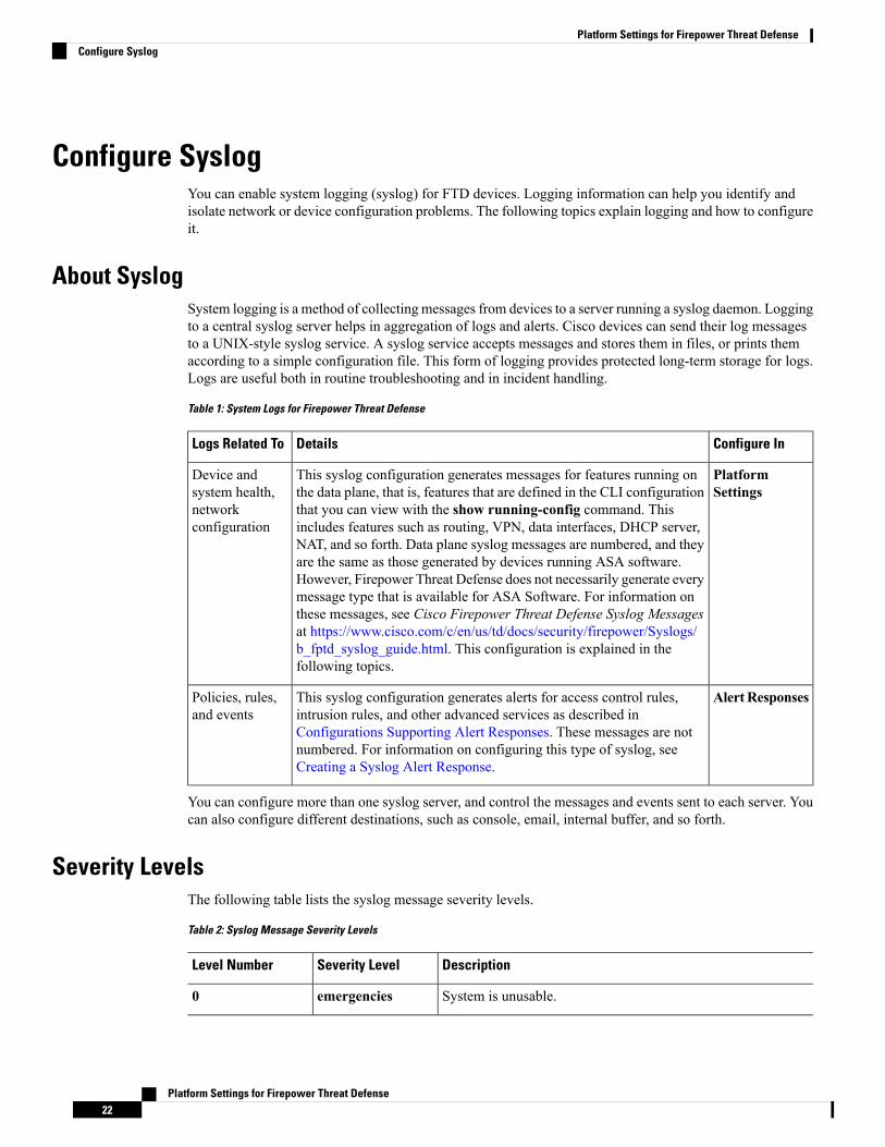
About SyslogSystem logging is a method of collecting messages from devices to a server running a syslog daemon. Loggingto a central syslog server helps in aggregation of logs and alerts. Cisco devices can send their log messagesto a UNIX-style syslog service. A syslog service accepts messages and stores them in files, or prints themaccording to a simple configuration file. This form of logging provides protected long-term storage for logs.Logs are useful both in routine troubleshooting and in incident handling.
Table 1: System Logs for Firepower Threat Defense
Configure InDetailsLogs Related To
PlatformSettings
This syslog configuration generates messages for features running onthe data plane, that is, features that are defined in the CLI configurationthat you can view with the show running-config command. Thisincludes features such as routing, VPN, data interfaces, DHCP server,NAT, and so forth. Data plane syslog messages are numbered, and theyare the same as those generated by devices running ASA software.However, Firepower Threat Defense does not necessarily generate everymessage type that is available for ASA Software. For information onthese messages, see Cisco Firepower Threat Defense Syslog Messagesat https://www.cisco.com/c/en/us/td/docs/security/firepower/Syslogs/b_fptd_syslog_guide.html. This configuration is explained in thefollowing topics.
Device andsystem health,networkconfiguration
AlertResponsesThis syslog configuration generates alerts for access control rules,intrusion rules, and other advanced services as described inConfigurations Supporting Alert Responses. These messages are notnumbered. For information on configuring this type of syslog, seeCreating a Syslog Alert Response.
Policies, rules,and events
You can configure more than one syslog server, and control the messages and events sent to each server. Youcan also configure different destinations, such as console, email, internal buffer, and so forth.
Severity LevelsThe following table lists the syslog message severity levels.
Table 2: Syslog Message Severity Levels
DescriptionSeverity LevelLevel Number
System is unusable.emergencies0
Platform Settings for Firepower Threat Defense22
Platform Settings for Firepower Threat DefenseConfigure Syslog
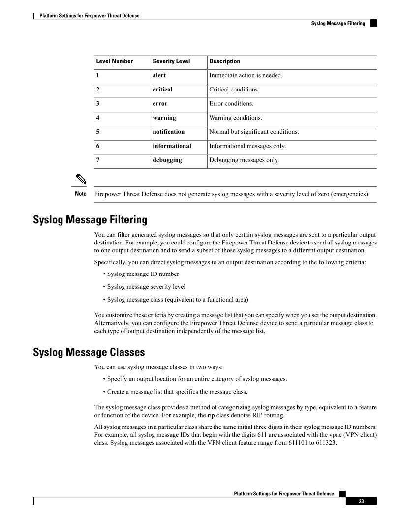
DescriptionSeverity LevelLevel Number
Immediate action is needed.alert1
Critical conditions.critical2
Error conditions.error3
Warning conditions.warning4
Normal but significant conditions.notification5
Informational messages only.informational6
Debugging messages only.debugging7
Firepower Threat Defense does not generate syslog messages with a severity level of zero (emergencies).Note
Syslog Message FilteringYou can filter generated syslog messages so that only certain syslog messages are sent to a particular outputdestination. For example, you could configure the Firepower Threat Defense device to send all syslogmessagesto one output destination and to send a subset of those syslog messages to a different output destination.
Specifically, you can direct syslog messages to an output destination according to the following criteria:
• Syslog message ID number
• Syslog message severity level
• Syslog message class (equivalent to a functional area)
You customize these criteria by creating a message list that you can specify when you set the output destination.Alternatively, you can configure the Firepower Threat Defense device to send a particular message class toeach type of output destination independently of the message list.
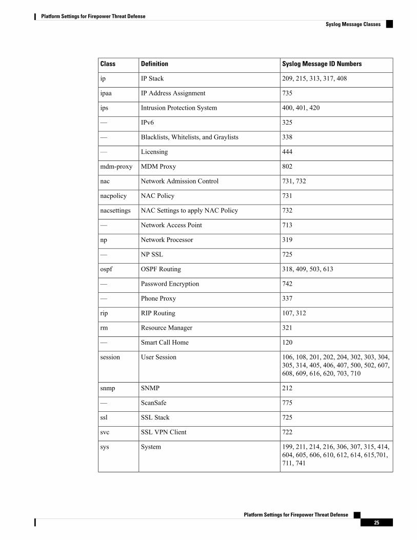
Syslog Message ClassesYou can use syslog message classes in two ways:
• Specify an output location for an entire category of syslog messages.
• Create a message list that specifies the message class.
The syslog message class provides a method of categorizing syslog messages by type, equivalent to a featureor function of the device. For example, the rip class denotes RIP routing.
All syslog messages in a particular class share the same initial three digits in their syslog message ID numbers.For example, all syslog message IDs that begin with the digits 611 are associated with the vpnc (VPN client)class. Syslog messages associated with the VPN client feature range from 611101 to 611323.
Platform Settings for Firepower Threat Defense23
Platform Settings for Firepower Threat DefenseSyslog Message Filtering
In addition, most of the ISAKMP syslog messages have a common set of prepended objects to help identifythe tunnel. These objects precede the descriptive text of a syslog message when available. If the object is notknown at the time that the syslog message is generated, the specific heading = value combination does notappear.
The objects are prefixed as follows:
Group = groupname, Username = user, IP = IP_address
Where the group is the tunnel-group, the username is the username from the local database or AAA server,and the IP address is the public IP address of the remote access client or Layer 2 peer.
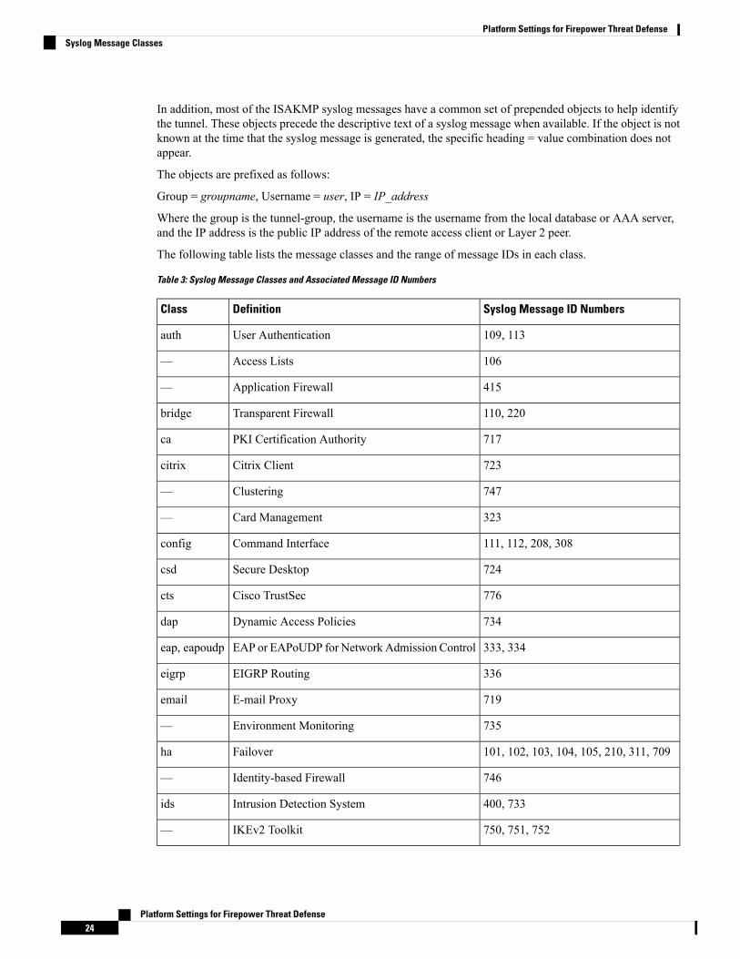
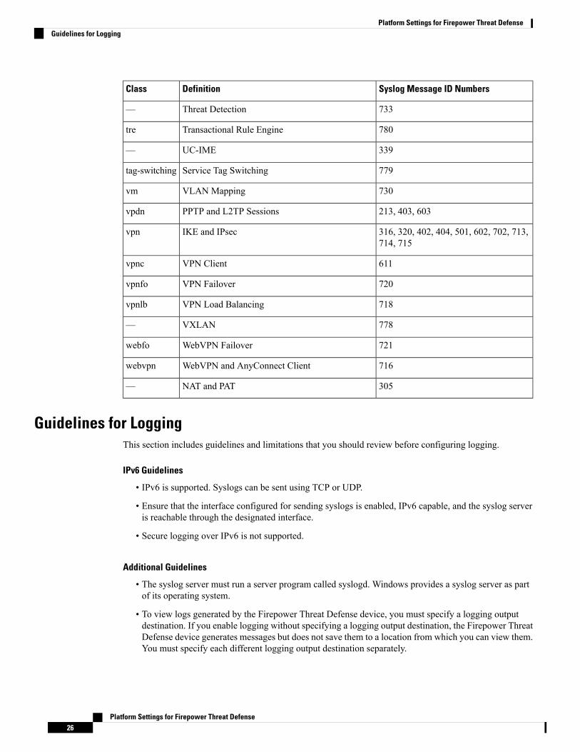
The following table lists the message classes and the range of message IDs in each class.
Table 3: Syslog Message Classes and Associated Message ID Numbers
Syslog Message ID NumbersDefinitionClass
109, 113User Authenticationauth
106Access Lists—
415Application Firewall—
110, 220Transparent Firewallbridge
717PKI Certification Authorityca
723Citrix Clientcitrix
747Clustering—
323Card Management—
111, 112, 208, 308Command Interfaceconfig
724Secure Desktopcsd
776Cisco TrustSeccts
734Dynamic Access Policiesdap
333, 334EAP or EAPoUDP for Network Admission Controleap, eapoudp
336EIGRP Routingeigrp
719E-mail Proxyemail
735Environment Monitoring—
101, 102, 103, 104, 105, 210, 311, 709Failoverha
746Identity-based Firewall—
400, 733Intrusion Detection Systemids
750, 751, 752IKEv2 Toolkit—
Platform Settings for Firepower Threat Defense24
Platform Settings for Firepower Threat DefenseSyslog Message Classes
Syslog Message ID NumbersDefinitionClass
209, 215, 313, 317, 408IP Stackip
735IP Address Assignmentipaa
400, 401, 420Intrusion Protection Systemips
325IPv6—
338Blacklists, Whitelists, and Graylists—
444Licensing—
802MDM Proxymdm-proxy
731, 732Network Admission Controlnac
731NAC Policynacpolicy
732NAC Settings to apply NAC Policynacsettings
713Network Access Point—
319Network Processornp
725NP SSL—
318, 409, 503, 613OSPF Routingospf
742Password Encryption—
337Phone Proxy—
107, 312RIP Routingrip
321Resource Managerrm
120Smart Call Home—
106, 108, 201, 202, 204, 302, 303, 304,305, 314, 405, 406, 407, 500, 502, 607,608, 609, 616, 620, 703, 710
User Sessionsession
212SNMPsnmp
775ScanSafe—
725SSL Stackssl
722SSL VPN Clientsvc
199, 211, 214, 216, 306, 307, 315, 414,604, 605, 606, 610, 612, 614, 615,701,711, 741
Systemsys
Platform Settings for Firepower Threat Defense25
Platform Settings for Firepower Threat DefenseSyslog Message Classes
Syslog Message ID NumbersDefinitionClass
733Threat Detection—
780Transactional Rule Enginetre
339UC-IME—
779Service Tag Switchingtag-switching
730VLAN Mappingvm
213, 403, 603PPTP and L2TP Sessionsvpdn
316, 320, 402, 404, 501, 602, 702, 713,714, 715
IKE and IPsecvpn
611VPN Clientvpnc
720VPN Failovervpnfo
718VPN Load Balancingvpnlb
778VXLAN—
721WebVPN Failoverwebfo
716WebVPN and AnyConnect Clientwebvpn
305NAT and PAT—
Guidelines for LoggingThis section includes guidelines and limitations that you should review before configuring logging.
IPv6 Guidelines
• IPv6 is supported. Syslogs can be sent using TCP or UDP.
• Ensure that the interface configured for sending syslogs is enabled, IPv6 capable, and the syslog serveris reachable through the designated interface.
• Secure logging over IPv6 is not supported.
Additional Guidelines
• The syslog server must run a server program called syslogd. Windows provides a syslog server as partof its operating system.
• To view logs generated by the Firepower Threat Defense device, you must specify a logging outputdestination. If you enable logging without specifying a logging output destination, the Firepower ThreatDefense device generates messages but does not save them to a location from which you can view them.You must specify each different logging output destination separately.
Platform Settings for Firepower Threat Defense26
Platform Settings for Firepower Threat DefenseGuidelines for Logging
• It is not possible to have two different lists or classes being assigned to different syslog servers or samelocations.
• You can configure up to 16 syslog servers.
• The syslog server should be reachable through the Firepower Threat Defense device. You should configurethe device to deny ICMP unreachable messages on the interface through which the syslog server isreachable and to send syslogs to the same server. Make sure that you have enabled logging for all severitylevels. To prevent the syslog server from crashing, suppress the generation of syslogs 313001, 313004,and 313005.
• The number of UDP connections for syslog is directly related to the number of CPUs on the hardwareplatform and the number of syslog servers you configure. At any point in time, there can be as manyUDP syslog connections as there are CPUs times the number of configured syslog servers. For example,for each syslog server:
• A Firepower 4110 can have up to 22 UDP syslog connections.
• A Firepower 4120 can have up to 46 UDP syslog connections.
This is the expected behavior. Note that the global UDP connection idle timeout applies to these sessions,and the default is 2 minutes. You can adjust that setting if you want to close these session more quickly,but the timeout applies to all UDP connections, not just syslog.
• When the Firepower Threat Defense device sends syslogs via TCP, the connection takes about one minuteto initiate after the syslogd service restarts.
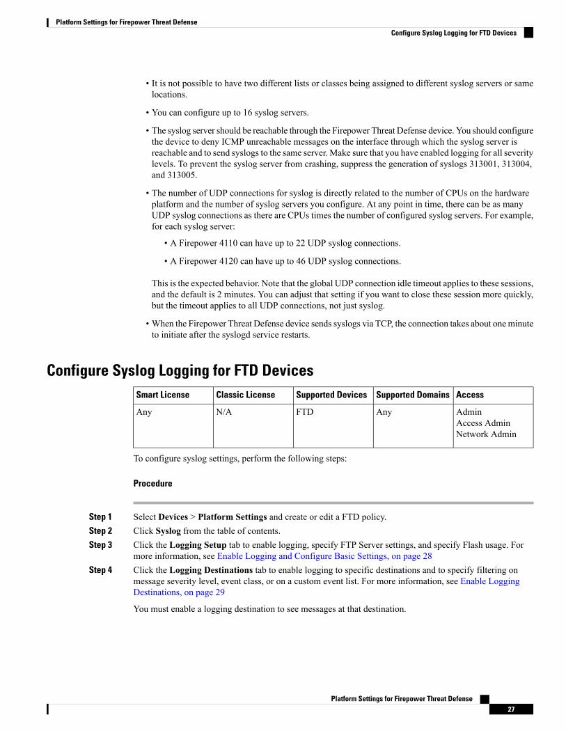
Configure Syslog Logging for FTD DevicesAccessSupported DomainsSupported DevicesClassic LicenseSmart License
AdminAccess AdminNetwork Admin
AnyFTDN/AAny
To configure syslog settings, perform the following steps:
Procedure
Step 1 Select Devices > Platform Settings and create or edit a FTD policy.Step 2 Click Syslog from the table of contents.Step 3 Click the Logging Setup tab to enable logging, specify FTP Server settings, and specify Flash usage. For
more information, see Enable Logging and Configure Basic Settings, on page 28Step 4 Click the Logging Destinations tab to enable logging to specific destinations and to specify filtering on
message severity level, event class, or on a custom event list. For more information, see Enable LoggingDestinations, on page 29
You must enable a logging destination to see messages at that destination.
Platform Settings for Firepower Threat Defense27
Platform Settings for Firepower Threat DefenseConfigure Syslog Logging for FTD Devices
Step 5 Click theE-mail Setup tab to specify the e-mail address that is used as the source address for syslog messagesthat are sent as e-mail messages. For more information, see Send Syslog Messages to an E-mail Address, onpage 30
Step 6 Click the Events List tab to define a custom event list that includes an event class, a severity level, and anevent ID. For more information, see Create a Custom Event List, on page 31
Step 7 Click the Rate Limit tab to specify the volume of messages being sent to all configured destinations anddefine the message severity level to which you want to assign rate limits. For more information, see Limit theRate of Syslog Message Generation, on page 32
Step 8 Click the Syslog Settings tab to specify the logging facility, enable the inclusion of a time stamp, and enableother settings to set up a server as a syslog destination. For more information, see Configure Syslog Settings,on page 33
Step 9 Click the Syslog Servers tab to specify the IP address, protocol used, format, and security zone for the syslogserver that is designated as a logging destination. For more information, see Configure a Syslog Server, onpage 34
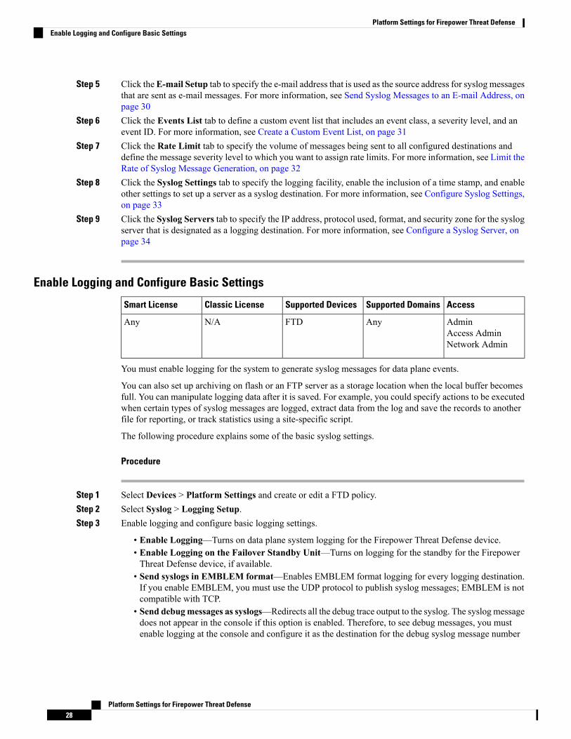
Enable Logging and Configure Basic Settings
AccessSupported DomainsSupported DevicesClassic LicenseSmart License
AdminAccess AdminNetwork Admin
AnyFTDN/AAny
You must enable logging for the system to generate syslog messages for data plane events.
You can also set up archiving on flash or an FTP server as a storage location when the local buffer becomesfull. You can manipulate logging data after it is saved. For example, you could specify actions to be executedwhen certain types of syslog messages are logged, extract data from the log and save the records to anotherfile for reporting, or track statistics using a site-specific script.
The following procedure explains some of the basic syslog settings.
Procedure
Step 1 Select Devices > Platform Settings and create or edit a FTD policy.Step 2 Select Syslog > Logging Setup.Step 3 Enable logging and configure basic logging settings.
• Enable Logging—Turns on data plane system logging for the Firepower Threat Defense device.• Enable Logging on the Failover Standby Unit—Turns on logging for the standby for the FirepowerThreat Defense device, if available.
• Send syslogs in EMBLEM format—Enables EMBLEM format logging for every logging destination.If you enable EMBLEM, you must use the UDP protocol to publish syslog messages; EMBLEM is notcompatible with TCP.
• Send debugmessages as syslogs—Redirects all the debug trace output to the syslog. The syslog messagedoes not appear in the console if this option is enabled. Therefore, to see debug messages, you mustenable logging at the console and configure it as the destination for the debug syslog message number
Platform Settings for Firepower Threat Defense28
Platform Settings for Firepower Threat DefenseEnable Logging and Configure Basic Settings
and logging level. The syslog message number used is 711011. Default logging level for this syslog isdebug.
• Memory Size of Internal Buffer—Specify the size of the internal buffer to which syslog messages aresaved if the logging buffer is enabled. When the buffer fills up, it is overwritten. The default is 4096bytes. The range is 4096 to 52428800.
Step 4 (Optional) Enable VPN logging by checking the Enable Logging to FMC check box. Choose the syslogseverity level for VPN messages from the Logging Level drop-down list.
For information on the levels, see Severity Levels, on page 22.
Step 5 (Optional) Configure an FTP server if you want to save log buffer contents to the server before the buffer isoverwritten. Specify the FTP Server information.
• FTP Server BufferWrap—To save the buffer contents to the FTP server before it is overwritten, checkthis box and enter the necessary destination information in the following fields. To remove the FTPconfiguration, deselect this option.
• IP Address—Select the host network object that contains the IP address of the FTP server.• User Name—Enter the user name to use when connecting to the FTP server.• Path—Enter the path, relative to the FTP root, where the buffer contents should be saved.• Password/ Confirm—Enter and confirm the password used to authenticate the user name to the FTPserver.
Step 6 (Optional) Specify Flash size if you want to save log buffer contents to flash before the buffer is overwritten.
• Flash—To save the buffer contents to the flash memory before it is overwritten, check this box.• Maximum flash to be used by logging (KB)—Specify the maximum space to be used in the flashmemory for logging(in KB). The range is 4-8044176 bytes.
• Minimum free space to be preserved (KB)—Specifies the minimum free space to be preserved in flashmemory (in KB). The range is 0-8044176 bytes.
Step 7 Click Save.
You can now click Deploy and deploy the policy to assigned devices. The changes are not active until youdeploy them.
Enable Logging Destinations
AccessSupported DomainsSupported DevicesClassic LicenseSmart License
AdminAccess AdminNetwork Admin
AnyFTDN/AAny
You must enable a logging destination to see messages at that destination. When enabling a destination, youmust also specify the message filter for the destination.
Procedure
Step 1 Select Devices > Platform Settings and create or edit a FTD policy.
Platform Settings for Firepower Threat Defense29
Platform Settings for Firepower Threat DefenseEnable Logging Destinations
Step 2 Select Syslog > Logging Destinations.Step 3 Click Add to enable a destination and apply a logging filter, or edit an existing destination.Step 4 In the Logging Destinations dialog box, select a destination and configure the filter to use for a destination:
a) Choose the destination you are enabling in the Logging Destination drop-down list. You can create onefilter per destination: Console, E-Mail, Internal buffer, SNMP trap, SSH Sessions, and Syslog servers.
Console and SSH session logging works in the diagnostic CLI only. Enter system supportdiagnostic-cli.
Note
b) In Event Class, choose the filter that will apply to all classes not listed in the table.
You can configure these filters:
• Filter on severity—Select the severity level. Messages at this level or higher are sent to thedestination
• Use Event List—Select the event list that defines the filter. You create these lists on the Event Liststab.
• Disable Logging—Prevents messages from being sent to this destination.
c) If you want to create filters per event class, click Add to create a new filter, or edit an existing filter, andselect the event class and severity level to limit messages in that class. Click OK to save the filter.
For an explanation of the event classes, see Syslog Message Classes, on page 23.
d) Click OK .
Step 5 Click Save.
You can now click Deploy and deploy the policy to assigned devices. The changes are not active until youdeploy them.
Send Syslog Messages to an E-mail Address
AccessSupported DomainsSupported DevicesClassic LicenseSmart License
AdminAccess AdminNetwork Admin
AnyFTDN/AAny
You can set up a list of recipients for syslog messages to be sent as e-mails.
Before you begin
• Configure an SMTP server on the SMTP Server platform settings page
• Enable Logging and Configure Basic Settings, on page 28
• Enable Logging Destinations
Platform Settings for Firepower Threat Defense30
Platform Settings for Firepower Threat DefenseSend Syslog Messages to an E-mail Address
Procedure
Step 1 Select Devices > Platform Settings and create or edit a FTD policy.Step 2 Select Syslog > Email Setup.Step 3 Specify the e-mail address that is used as the source address for syslog messages that are sent as e-mail
messages.Step 4 Click Add to enter a new e-mail address recipient of the specified syslog messages.Step 5 Choose the severity level of the syslog messages that are sent to the recipient from the drop-down list.
The syslog message severity filter used for the destination e-mail address causes messages of the specifiedseverity level and higher to be sent. For information on the levels, see Severity Levels, on page 22.
Step 6 Click OK.Step 7 Click Save.
You can now click Deploy and deploy the policy to assigned devices. The changes are not active until youdeploy them.
Create a Custom Event List
AccessSupported DomainsSupported DevicesClassic LicenseSmart License
AdminAccess AdminNetwork Admin
AnyFTDN/AAny
An event list is a custom filter you can apply to a logging destination to control which messages are sent tothe destination. Normally, you filter messages for a destination based on severity only, but you can use anevent list to fine-tune which messages are sent based on a combination of event class, severity, and messageidentifier (ID).
Creating a custom event list is a two-step process. You create a custom list in the Event Lists tab, and thenuse the event list to define the logging filter for the various types of destination, in the Logging Destinationstab.
Procedure
Step 1 Select Devices > Platform Settings and create or edit a FTD policy.Step 2 Select Syslog > Events List.Step 3 Configure an event list.
a) Click Add to add a new list, or edit an existing list.b) Enter a name for the event list in the Name field. Spaces are not allowed.c) To identify messages based on severity or event class, select the Severity/Event Class tab and add or edit
entries.
For information on the available classes see Syslog Message Classes, on page 23.
For information on the levels, see Severity Levels, on page 22.
Platform Settings for Firepower Threat Defense31
Platform Settings for Firepower Threat DefenseCreate a Custom Event List
Certain event classes are not applicable for the device in transparent mode. If such options are configuredthen they will be bypassed and not deployed.
d) To identify messages specifically by message ID, select theMessage ID tab and add or edit the IDs.
You can enter a range of IDs using a hyphen, for example, 100000-200000. IDs are six digits. Forinformation on how the initial three digits map to features, see Syslog Message Classes, on page 23.
For specific message numbers, see Cisco ASA Series Syslog Messages.
e) Click OK to save the event list.
Step 4 Click the Logging Destinations tab and add or edit the destination that should use the filter.
See Enable Logging Destinations, on page 29.
Step 5 Click Save.
You can now click Deploy and deploy the policy to assigned devices. The changes are not active until youdeploy them.
Limit the Rate of Syslog Message Generation
AccessSupported DomainsSupported DevicesClassic LicenseSmart License
AdminAccess AdminNetwork Admin
AnyFTDN/AAny
You can limit the rate at which syslog messages are generated by severity level or message ID. You canspecify individual limits for each logging level and each Syslog message ID. If the settings conflict, the Syslogmessage ID limits take precedence.
Procedure
Step 1 Select Devices > Platform Settings and create or edit a FTD policy.Step 2 Select Syslog > Rate Limit.Step 3 To limit message generation by severity level, clickAdd on theLogging Level tab and configure the following
options:
• Logging Level—The severity level you are rate limiting. For information on the levels, see SeverityLevels, on page 22.
• Number ofmessages—Themaximum number of messages of the specified type allowed in the specifiedtime period.
• Interval—The number of seconds before the rate limit counter resets.
Step 4 Click OK.Step 5 To limit message generation by syslog message ID, click Add on the Syslog Level tab and configure the
following options:
• Syslog ID—The syslog message ID you are rate limiting. For specific message numbers, see Cisco ASASeries Syslog Messages.
Platform Settings for Firepower Threat Defense32
Platform Settings for Firepower Threat DefenseLimit the Rate of Syslog Message Generation
• Number ofmessages—Themaximum number of messages of the specified type allowed in the specifiedtime period.
• Interval—The number of seconds before the rate limit counter resets.
Step 6 Click OK.Step 7 Click Save.
You can now click Deploy and deploy the policy to assigned devices. The changes are not active until youdeploy them.
Configure Syslog Settings
AccessSupported DomainsSupported DevicesClassic LicenseSmart License
AdminAccess AdminNetwork Admin
AnyFTDN/AAny
You can configure general syslog settings to set the facility code to be included in syslog messages that aresent to syslog servers, specify whether a timestamp is included in each message, specify the device ID toinclude in messages, view and modify the severity levels for messages, and disable the generation of specificmessages.
Procedure
Step 1 Select Devices > Platform Settings and create or edit a FTD policy.Step 2 Select Syslog > Syslog Settings.Step 3 Select a system log facility for syslog servers to use as a basis to file messages in the Facility drop-down list.
The default is LOCAL4(20), which is what most UNIX systems expect. However, because your networkdevices share available facilities, you might need to change this value for system logs.
Step 4 Select the Enable timestamp on each syslog message check box to include the date and time a message wasgenerated in the syslog message.
Timestamp timezone is always UTC.
Step 5 If you want to add a device identifier to syslog messages (which is placed at the beginning of the message),check the Enable Syslog Device ID check box and then select the type of ID.
• Interface—To use the IP address of the selected interface, regardless of the interface through which theappliance sends the message. Select the security zone that identifies the interface. The zone must mapto a single interface.
• User Defined ID—To use a text string (up to 16 characters) of your choice.• Host Name—To use the hostname of the device.
Step 6 Use the Syslog Message table to alter the default settings for specific syslog messages. You need to configurerules in this table only if you want to change the default settings. You can change the severity assigned to amessage, or you can disable the generation of a message.
By default, Netflow is enabled and the entries are shown in the table.
Platform Settings for Firepower Threat Defense33
Platform Settings for Firepower Threat DefenseConfigure Syslog Settings
a) To suppress syslog messages that are redundant because of Netflow, select Netflow Equivalent Syslogs.
This adds the messages to the table as suppressed messages.
If any of these syslog equivalents are already in the table, your existing rules are not overwritten.Note
b) To add a rule, click the Add button.c) You select the message number whose configuration you want to change, from the Syslog ID drop down
list and then select the new severity level from the Logging Level drop down list, or select Suppressedto disable the generation of the message. Typically, you would not change the severity level and disablethe message, but you can make changes to both fields if desired.
d) Click OK to add the rule to the table.
Step 7 Click Save.
You can now click Deploy and deploy the policy to assigned devices. The changes are not active until youdeploy them.
What to do next
• Deploy configuration changes; see Deploy Configuration Changes.
Configure a Syslog Server
AccessSupported DomainsSupported DevicesClassic LicenseSmart License
AdminAccess AdminNetwork Admin
AnyFTDN/AAny
To configure a syslog server to handle messages generated from the data plane, perform the following steps.
Procedure
Step 1 Select Devices > Platform Settings and create or edit a FTD policy.Step 2 Select Syslog > Syslog Server.Step 3 Check the Allow user traffic to pass when TCP syslog server is down check box, to allow traffic if any
syslog server that is using the TCP protocol is down.Step 4 Enter a size of the queue for storing syslog messages on the security appliance when syslog server is busy in
theMessage queue size (messages) field. The minimum is 1 message. The default is 512. Specify 0 to allowan unlimited number of messages to be queued (subject to available block memory).
Step 5 Click Add to add a new syslog server.a) In the IP Address drop-down list, select a network host object that contains the IP address of the syslog
server.b) Choose the protocol (either TCP or UDP) and enter the port number for communications between the
Firepower Threat Defense device and the syslog server.
UDP is faster and uses less resources on the device than TCP.
Platform Settings for Firepower Threat Defense34
Platform Settings for Firepower Threat DefenseConfigure a Syslog Server
The default ports are 514 for UDP, 1470 for TCP. Valid non-default port values for either protocol are1025 through 65535.
c) Check the Log messages in Cisco EMBLEM format (UDP only) check box to specify whether to logmessages in Cisco EMBLEM format (available only if UDP is selected as the protocol).
d) Check the Enable Secure Syslog check box to encrypt the connection between the device and serverusing SSL/TLS over TCP.
e) Add the zones that contain the interfaces used to communicate with the syslog server. For interfaces notin a zone, you can type the interface name into the field below the Selected Zones/Interface list and clickAdd. These rules will be applied to a device only if the device includes the selected interfaces or zones.
If the syslog server is on the network attached to the physical Management interface, you musttype the name of that interface into the Interface Name field below the Selected SecurityZones list and click Add. You must also configure this name (if not already configured), andan IP address, for the Diagnostic interface (edit the device from the Device Management pageand select the Interfaces tab). For more information about the management/diagnostic interface,see Diagnostic Interface.
Note
f) Click OK.
Step 6 Click Save.
You can now click Deploy and deploy the policy to assigned devices. The changes are not active until youdeploy them.
What to do next
• Deploy configuration changes; see Deploy Configuration Changes.
Configure Global TimeoutsAccessSupported DomainsSupported DevicesClassic LicenseSmart License
AdminAccess AdminNetwork Admin
AnyFTDN/AAny
You can set the global idle timeout durations for the connection and translation slots of various protocols. Ifthe slot has not been used for the idle time specified, the resource is returned to the free pool.
You can also set a time out for console sessions with the device.
Procedure
Step 1 Select Devices > Platform Settings and create or edit a FTD policy.Step 2 Select Timeouts.Step 3 Configure the timeouts you want to change.
Platform Settings for Firepower Threat Defense35
Platform Settings for Firepower Threat DefenseConfigure Global Timeouts
For any given setting, select Custom to define your own value, Default to return to the system default value.In most cases, the maximum timeout is 1193 hours.
You can disable some timeouts by selecting Disable.
• Console Timeout—The idle time until a connection to the console is closed, range is 0 or 5 to 1440minutes. The default is 0, which means the session does not time out. If you change the value, existingconsole sessions use the old timeout value. The new value applies to new connections only.
• Translation Slot (xlate)—The idle time until a NAT translation slot is freed. This duration must be atleast 1 minute. The default is 3 hours.
• Connection (Conn)—The idle time until a connection slot is freed. This duration must be at least 5minutes. The default is 1 hour.
• Half-Closed—The idle time until a TCP half-closed connection closes. The minimum is 30 seconds.The default is 10 minutes.
• UDP—The idle time until a UDP connection closes. This duration must be at least 1 minute. The defaultis 2 minutes.
• ICMP—The idle time after which general ICMP states are closed. The default (and minimum) is 2seconds.
• RPC/Sun RPC—The idle time until a SunRPC slot is freed. This duration must be at least 1 minute.The default is 10 minutes.
• H.225—The idle time until an H.225 signaling connection closes. The default is 1 hour. To close aconnection immediately after all calls are cleared, a timeout of 1 second (0:0:1) is recommended.
• H.323—The idle time after which H.245 (TCP) and H.323 (UDP) media connections close. The default(and minimum) is 5 minutes. Because the same connection flag is set on both H.245 and H.323 mediaconnections, the H.245 (TCP) connection shares the idle timeout with the H.323 (RTP and RTCP) mediaconnection.
• SIP—The idle time until a SIP signaling port connection closes. This duration must be at least 5 minutes.The default is 30 minutes.
• SIP Media—The idle time until a SIP media port connection closes. This duration must be at least 1minute. The default is 2 minutes. The SIP media timer is used for SIP RTP/RTCP with SIP UDP mediapackets, instead of the UDP inactivity timeout.
• SIP Disconnect—The idle time after which SIP session is deleted if the 200 OK is not received for aCANCEL or a BYE message, between 0:0:1 and 0:10:0. The default is 2 minutes (0:2:0).
• SIP Invite—The idle time after which pinholes for PROVISIONAL responses and media xlates will beclosed, between 0:1:0 and 00:30:0. The default is 3 minutes (0:3:0).
• SIP Provisional Media—The timeout value for SIP provisional media connections, between 1 and 30minutes. The default is 2 minutes.
• Floating Connection—When multiple routes exist to a network with different metrics, the ASA usesthe one with the best metric at the time of connection creation. If a better route becomes available, thenthis timeout lets connections be closed so a connection can be reestablished to use the better route. Thedefault is 0 (the connection never times out). To make it possible to use better routes, set the timeout toa value between 0:0:30 and 1193:0:0.
Platform Settings for Firepower Threat Defense36
Platform Settings for Firepower Threat DefenseConfigure Global Timeouts
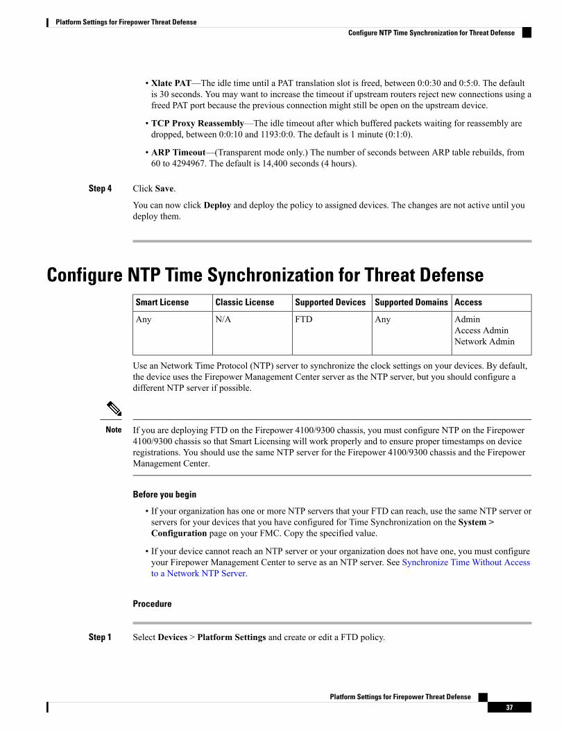
• Xlate PAT—The idle time until a PAT translation slot is freed, between 0:0:30 and 0:5:0. The defaultis 30 seconds. You may want to increase the timeout if upstream routers reject new connections using afreed PAT port because the previous connection might still be open on the upstream device.
• TCP Proxy Reassembly—The idle timeout after which buffered packets waiting for reassembly aredropped, between 0:0:10 and 1193:0:0. The default is 1 minute (0:1:0).
• ARP Timeout—(Transparent mode only.) The number of seconds between ARP table rebuilds, from60 to 4294967. The default is 14,400 seconds (4 hours).
Step 4 Click Save.
You can now click Deploy and deploy the policy to assigned devices. The changes are not active until youdeploy them.
Configure NTP Time Synchronization for Threat DefenseAccessSupported DomainsSupported DevicesClassic LicenseSmart License
AdminAccess AdminNetwork Admin
AnyFTDN/AAny
Use an Network Time Protocol (NTP) server to synchronize the clock settings on your devices. By default,the device uses the Firepower Management Center server as the NTP server, but you should configure adifferent NTP server if possible.
If you are deploying FTD on the Firepower 4100/9300 chassis, you must configure NTP on the Firepower4100/9300 chassis so that Smart Licensing will work properly and to ensure proper timestamps on deviceregistrations. You should use the same NTP server for the Firepower 4100/9300 chassis and the FirepowerManagement Center.
Note
Before you begin
• If your organization has one or more NTP servers that your FTD can reach, use the same NTP server orservers for your devices that you have configured for Time Synchronization on the System >Configuration page on your FMC. Copy the specified value.
• If your device cannot reach an NTP server or your organization does not have one, you must configureyour Firepower Management Center to serve as an NTP server. See Synchronize Time Without Accessto a Network NTP Server.
Procedure
Step 1 Select Devices > Platform Settings and create or edit a FTD policy.
Platform Settings for Firepower Threat Defense37
Platform Settings for Firepower Threat DefenseConfigure NTP Time Synchronization for Threat Defense
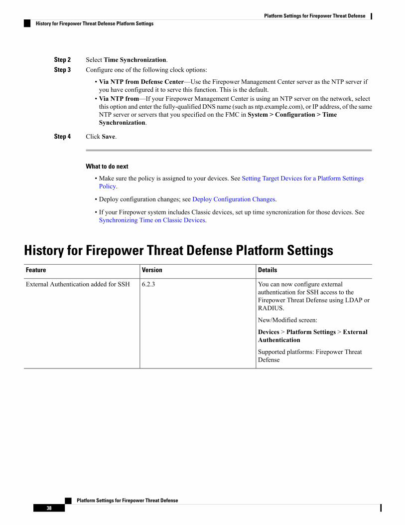
Step 2 Select Time Synchronization.Step 3 Configure one of the following clock options:
• Via NTP from Defense Center—Use the Firepower Management Center server as the NTP server ifyou have configured it to serve this function. This is the default.
• Via NTP from—If your Firepower Management Center is using an NTP server on the network, selectthis option and enter the fully-qualified DNS name (such as ntp.example.com), or IP address, of the sameNTP server or servers that you specified on the FMC in System > Configuration > TimeSynchronization.
Step 4 Click Save.
What to do next
• Make sure the policy is assigned to your devices. See Setting Target Devices for a Platform SettingsPolicy.
• Deploy configuration changes; see Deploy Configuration Changes.
• If your Firepower system includes Classic devices, set up time syncronization for those devices. SeeSynchronizing Time on Classic Devices.
History for Firepower Threat Defense Platform SettingsDetailsVersionFeature
You can now configure externalauthentication for SSH access to theFirepower Threat Defense using LDAP orRADIUS.
New/Modified screen:
Devices > Platform Settings > ExternalAuthentication
Supported platforms: Firepower ThreatDefense
6.2.3External Authentication added for SSH
Platform Settings for Firepower Threat Defense38
Platform Settings for Firepower Threat DefenseHistory for Firepower Threat Defense Platform Settings
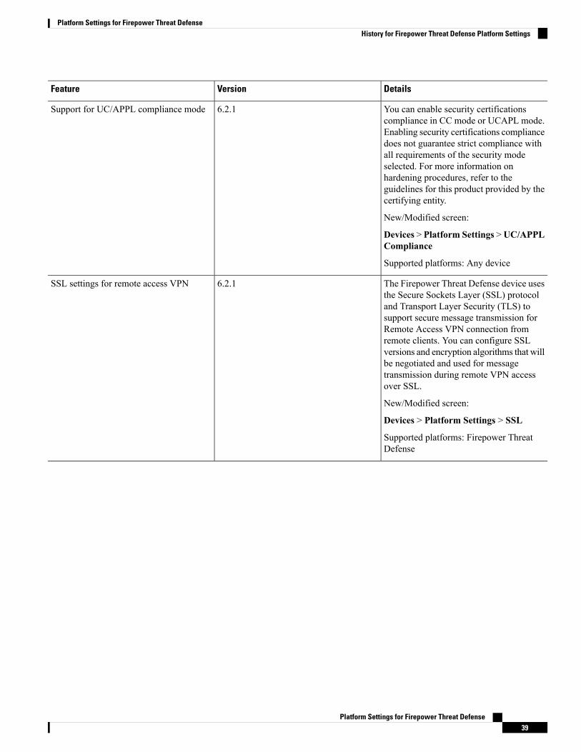
DetailsVersionFeature
You can enable security certificationscompliance in CC mode or UCAPL mode.Enabling security certifications compliancedoes not guarantee strict compliance withall requirements of the security modeselected. For more information onhardening procedures, refer to theguidelines for this product provided by thecertifying entity.
New/Modified screen:
Devices > Platform Settings >UC/APPLCompliance
Supported platforms: Any device
6.2.1Support for UC/APPL compliance mode
The Firepower Threat Defense device usesthe Secure Sockets Layer (SSL) protocoland Transport Layer Security (TLS) tosupport secure message transmission forRemote Access VPN connection fromremote clients. You can configure SSLversions and encryption algorithms that willbe negotiated and used for messagetransmission during remote VPN accessover SSL.
New/Modified screen:
Devices > Platform Settings > SSL
Supported platforms: Firepower ThreatDefense
6.2.1SSL settings for remote access VPN
Platform Settings for Firepower Threat Defense39
Platform Settings for Firepower Threat DefenseHistory for Firepower Threat Defense Platform Settings
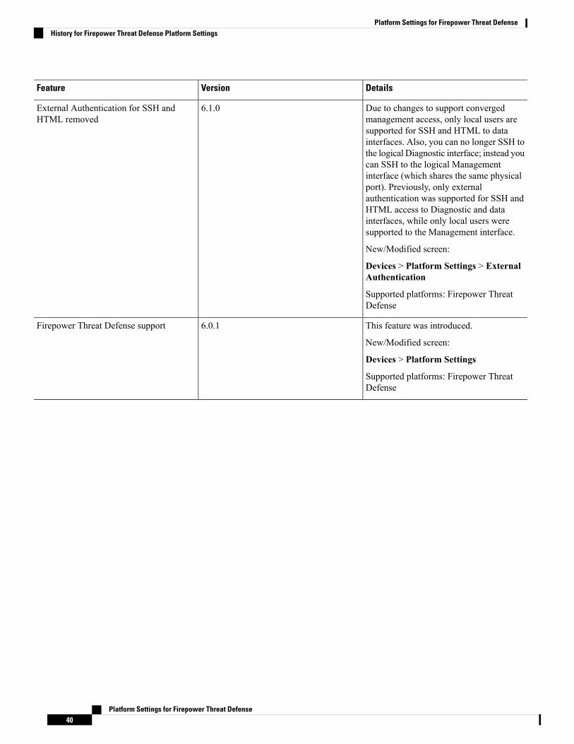
DetailsVersionFeature
Due to changes to support convergedmanagement access, only local users aresupported for SSH and HTML to datainterfaces. Also, you can no longer SSH tothe logical Diagnostic interface; instead youcan SSH to the logical Managementinterface (which shares the same physicalport). Previously, only externalauthentication was supported for SSH andHTML access to Diagnostic and datainterfaces, while only local users weresupported to the Management interface.
New/Modified screen:
Devices > Platform Settings > ExternalAuthentication
Supported platforms: Firepower ThreatDefense
6.1.0External Authentication for SSH andHTML removed
This feature was introduced.
New/Modified screen:
Devices > Platform Settings
Supported platforms: Firepower ThreatDefense
6.0.1Firepower Threat Defense support
Platform Settings for Firepower Threat Defense40
Platform Settings for Firepower Threat DefenseHistory for Firepower Threat Defense Platform Settings