plc, dcs, pc control backup station user's manual
TRANSCRIPT

M531 V , MAY 20
5 3 1
5 3 1
PLC, DCS, PC CONTROL BACKUP STATIONUSER'S MANUAL

531 User's Manual Table of Contents i
Contents
pageAbout This Manual:Throughout this User’s Manual willappear NOTEs, CAUTIONs andWARNINGs, usually in boldface.Please heed these safety and goodpractice notices for the protection ofyou and your equipment.
CONTENTS
FIGURE LIST .......................................................................................... iii
CHAPTER 1INTRODUCTION ............................................................................. 1Conforming What Is Included .......................................................... 1Order Code ...................................................................................... 2Basic Operation ............................................................................... 3Where To Go Next ........................................................................... 3Text Formatting in This Manual ...................................................... 3
CHAPTER 2INTERFACE & BASIC OPERATION ............................................. 5Displays............................................................................................ 5Icons ................................................................................................. 5Keys ................................................................................................. 6Basic Operating Procedures ........................................................... 7Alarms .............................................................................................. 8
CHAPTER 3HARDWARE CONFIGURATION .................................................... 9Accessing and Changing Jumpers ............................................... 11Adding or Changing Output Modules ............................................ 12Where to Go Next .......................................................................... 13
CHAPTER 4MOUNTING AND WIRING ............................................................ 15System Planning ............................................................................ 15Mounting the Station ...................................................................... 15Wiring the 531 Inputs..................................................................... 16
A. AC Power .......................................................................... 17B. Process Variable ............................................................... 17C. Digital Inputs ..................................................................... 18D. Remote Setpoint Indicator ................................................ 19
Wiring the 531 Outputs .................................................................. 19A. CV Output ......................................................................... 19B Mechanical Relay Output ................................................. 19C Solid State Relay (Triac) Output ...................................... 19D. DC Logic (SSR Drive) Output .......................................... 19
Wiring for Serial Communications ................................................. 20Where to Go Next .......................................................................... 20
CHAPTER 5SOFTWARE CONFIGURATION .................................................. 21Mode Overview .............................................................................. 21Menus............................................................................................. 22Smart Menus .................................................................................. 22Software Configuration Procedures .............................................. 23Guide to Set up Parameters .......................................................... 25
CONFIG. ................................................................................ 25LOCAL OUT. ......................................................................... 28PV INPUT .............................................................................. 29CUST. LINR. ......................................................................... 31
Contents
ii Table of Contents 531 User's Manual
page
RSP INPUT ............................................................................ 32ALARMS ................................................................................ 33SECURITY ............................................................................. 35SER. COMM........................................................................... 36OPERATION .......................................................................... 37
Parameter Value Charts .................................................................. 39
CHAPTER 6531 APPLICATIONS ...................................................................... 45531 Operation ................................................................................. 45Alarms............................................................................................. 46Digital Inputs ................................................................................... 50Watchdog Monitor ........................................................................... 51Process Variable and Setpoint ........................................................ 51Input Linearization ........................................................................... 53
Thermocouple and RTD Linearization .................................... 53Square Root Linearization ...................................................... 53Custom Linearization .............................................................. 53
Ramp to a Control Value ................................................................. 54Security ........................................................................................... 55Process Variable Reading Correction ............................................. 56Serial Communications ................................................................... 56
APPENDIX AMODE, MENU & PARAMETER FLOWCHART............................ A-1
APPENDIX BPARTS LIST ................................................................................. B-1
APPENDX CTROUBLESHOOTING ................................................................. C-1
APPENDIX DCALIBRATION ............................................................................. D-1Regarding Calibration ................................................................... D-1RTD and VmA Input Calibration .................................................... D-2Thermocouple & Cold Junction Calibration ................................... D-3Milliamp Output Calibration ........................................................... D-4Reset Menu Data .......................................................................... D-4Hardware Scan ............................................................................. D-5Quick Calibration Procedure ......................................................... D-5
APPENDIX ESPECIFICATIONS ........................................................................ E-1

531 User's Manual Table of Contents iii
Contents
Figure............. Title ............................................................................ Page
Figure 2.1 ......531 Operator Interface ......................................................... 5
Figure 2.2 ......Before and After Acknowledging an Alarm ............................. 8
Figure 3.1 ......Location of Printed Circuit Boards ......................................... 9
Figure 3.2 ...... Jumper Locations on Microcontroller Board ......................... 10
Figure 3.3 ......The Option Circuit Board .................................................... 10
Figure 3.4 ......The Power Supply Circuit Board ......................................... 10
Figure 3.5 ......Output Module ................................................................... 13
Figure 4.1 ......531 Instrument Panel and Cutout Dimensions ..................... 15
Figure 4.2 ......Mounting Brackets ............................................................. 16
Figure 4.3 ......531 Rear Terminals ............................................................ 17
Figure 4.4 ......Output Wiring for the 531 .................................................... 19
Figure 4.5 ......Serial Communications Terminals ....................................... 20
Figure 5.1 ......Menu Flowchart for Set Up ................................................. 21
Figure 5.2 ...... Independent vs. Dependent Parameters ............................. 22
Figure 5.3 ......Keys to Enter and Move Through Set Up Mode .................... 23
Figure 6.1 ......Alarm Examples ................................................................. 49
Figure 6.2 ......Square Root Linearization Formula ..................................... 53
Figure 6.3 ......Custom Linearization Curve ................................................ 54
Figure D.1 ..... Flowchart to Access Parts of Calibration Menu Block ......... D-1
Figure D.2 ..... Microcontroller Circuit Board ............................................. D-2
Figure D.3 ..... Calibration Wiring ............................................................. D-2
Figure D.3a ...Calibration Wiring (continued) ........................................... D-3
Figure D.4 ..... Thermocouple & Cold Junction Calibration Wiring .............. D-3
Figure D.5 ..... Milliamp Calibration Wiring ................................................ D-4

Contents
iv Table of Contents 531 User's Manual

531 User's Manual Chapter 1, Introduction 1
Introduction
CHAPTER 1INTRODUCTIONThe 531 PID Backup Station ensures the integrity of your processes withmaximum reliability. Isolated inputs and outputs guard against electrical inter-ference, the front face meets NEMA 4X standards for watertight operation, andthe rugged case and sturdy rubber keys enhance durability.The 531 has three digital display areas, two of which offer up to 9 characters oftrue alphanumerics. The bright, crisp vacuum fluorescent displays offer betterreadability than any other display technology. Additional operator friendly fea-tures include: custom programmable alarm messages, keys that illuminatewhen in use, and an easy-to-use menu system.
The 531 automatically provides PID backup control for critical control loops. InHost Mode, the control signal passes from the Host device through the 531without any degradation. A Host device may be a PLC, DCS, or process con-troller. The 531 switches to Automatic (PID) Mode upon keypad selection,digital input, or loss of the Host signal, and generates a control signal based onits own PID calculations. The control setpoint may be one or two presetsetpoints, or transmitted to the 531. The 531 can also be switched to ManualMode, in which the operator can manually adjust the output. The 531 will trans-fer/return to Host Mode upon keypad selection, opening of the digital input orreturn of the Host signal.
CONFIRMING WHAT IS INCLUDEDWith your 531 PID Backup Station, you should have received:• 1 531 User’s Manual• Mounting hardware set• 1 sheet of engineering unit adhesive labels• 1 Terminal labelYou can determine the installed outputs of your station by comparing your productnumber to the Order Code below. The product number is printed on the label onthe top of the controller case.
OUT1 2ALM1 2
INPUTSHOST Signal
Process VariableRemote Setpoint
Digital InputsSerial Communications
OUTPUTSHOST SignalControl OutputAlarm(s)Serial Communications
Thank you for selecting the 531PID Backup Station. It is the mostsophisticated instrument in itsclass and will provide you withyears of reliable, trouble-freeperformance.
Specifications and information subject to change without notice.
Note: that the 531 PID Backup Stationis not a point of failure; removing it fromthe case or powering down while inHost Mode will not disturb the Hostsignal.


531 User's Manual Chapter 1, Introduction 3
Introduction
Host Mode: The 531 operates as a remote station that passes a CV di-rectly from a host to a controlled device. In this mode, the SP but not the CV(output) can be altered. Special “set up” parameters can be accessed, andthe 531 can be transferred into either of the other operating modes.Automatic Mode: The 531 sends output to the final device as provided byits own PID calculations. In this mode, the SP but not the CV (output) canbe altered. The “set up” parameters may not be accessed, but the 531 canbe transferred to either of the other operating modes.Manual Mode. An operator provides manual output to the controlled de-vice. Both the SP and the CV can be altered, and the 531 can be transferredto either of the other two operating modes.
The 531 also has a set up, or “configuration” mode in which the user configuresthe special functions of the 531, like inputs and outputs, alarms and PID opera-tion. There are 9 menus in set up mode: eight are for instrument set up, and theninth, OPERATION, configures the operational aspects of the 531.
WHERE TO GO NEXT• First time users should read through this entire manual. Continue to Chap-
ter 2 for basic interface and operation information. Then read Chapter 3 forimportant installation guidelines.
• Experienced users may continue on to Chapter 5 for details on the configu-ration features of the 531.
• Appendix 1 contains flowchart references for all 531 parameters, menusand modes.
TEXT FORMATTING IN THIS MANUALFeature FormatMode Automatic, Manual, Host ModeKEYS SET PT DISPLAY
or
ICONS OUT, ALMMENUS CONFIG., TUNINGPARAMETERS CYCLE TM:1, MIN.OUT2PARAMETER VALUES OFF, SETPOINT, LAST OUT.DISPLAY MESSAGES TOO HOT, OUT%,
SET PT DISPLAY

Introduction
4 Chapter 1, Introduction 531 User's Manual

Interface/Operation
531 User's Manual Chapter 2, Interface and Basic Operation 5
MANUAL DISPLAY ACK
FASTMENUHOST
OUT1 2ALM1 2
Location foridentification label
1st Display
2nd Display
3rd Display
Icons
Keys
531
CHAPTER 2INTERFACE AND BASIC OPERATIONThe individual software and hardware options of your station determine the in-formation it displays. Compare the product number on the unit label to the OrderCode in Chapter 1 for more information. A “smart menu” feature of the 531 al-lows only those messages relevant to your individual hardware (and software)configuration to appear in the displays.
1st Display• 5 digits, seven segments. Height is 15mm (0.6in).• Normally displays the Process Variable (PV).
If station loses signal, “--------” displays.
2nd Display• 9 characters, 14 segment alphanumeric. Height is 6mm (0.25in).• Displays the CV output (OUT) or the setpoint (SP). To change the displayed
value, press the DISPLAY key.• When in configuration menus, displays the menu and parameter names
3rd Display• 9 characters, 14 segment. Height is 6mm (0.25in).• Displays user-selectable station name if no alarms are queued.• Displays any error or alarm in two-second alternating messages.• When in configuration menus, displays the parameter values.
ICONS:ALM 1, ALM2: Indicates respective alarm(s) is/are active.
OUT 1, OUT2: Indicates respective output(s) is/are active.
NOTE::Any modifications to the factorysettings of the output modules willalter the Model Number displayedupon power-up from the original theProduct Code on the label.
Figure 2.1531 Operator Interface
ALM ALM ALM1 2 1 2
OUT OUT OUT1 2 1 2

Interface/Operation
6 Chapter 2, Interface and Basic Operation 531 User's Manual
MANUAL
HOST
DISPLAY
MENU
ACK
FAST
FAST
FAST
FAST MENU
NOTE:Refer to Chapter 3, or Appendix 1 fordetails on menu, mode and parametertransitions
Illuminated Key
Station is in Manual Mode. Whennot illuminated, the station is ineither Host or Automatic Mode.
531 is passing Host signalthrough.
Key does not light.
531 is in configuration (set up)mode.
An acknowledgable alarm exists.
Key does not light.
Keys do not light.
N/A
N/A
Press Key (s)
Transfers station from Host orAutomatic Mode to Manual Mode,or from Manual to Automatic.
Toggles between Host and eitherAutomatic or Manual Mode(depending on validity of the PV).
Exits the configuration (set up)menus and returns station tooperating mode.
Provides entry into the OPERA-TION set up menu.
Acknowledges alarms.
Functions as a “shift” key or for usewith other keys.
Increases or decreases the value orselection of the current parameter.
Changes parameter value orselection at a faster rate.
In Host or Manual Mode, providesentry into the other eight set upmenus. When under configuration,advances from menu to menu.
o r
+
o r
+
+
KEYS

Interface/Operation
531 User's Manual Chapter 2, Interface and Basic Operation 7
BASIC OPERATING PROCEDURESTo transfer from Host to Automatic Mode1. Press the HOST key once. The 531 will transfer to Automatic Mode as
long as the PV input is valid (else, it transfers to Manual Mode).2. The HOST key and MANUAL key will be off.3. The 531 stops passing the Host signal, and transmits its own output that
based on PID, with a bumpless transfer.To transfer from Host to Manual Mode1. Press the MANUAL key. The 531 will transfer to Manual Mode.2. The HOST key will extinguish, and the MANUAL key will light.3. The 531 stops passing the Host signal, and transmits a manual output to
the final control element. This will be a bumpless transfer.To transfer from Automatic to Manual Mode1. When in Automatic Mode, press the MANUAL key.2. The MANUAL key will light.3. The 531 stops transmitting the PID output and transmits a manual output
to the final control element. This will be a bumpless transfer.To transfer from Automatic/Manual Mode to Host Mode1. Press the HOST key. The 531 will transfer to Host Mode as long as the CV
signal is valid (otherwise, it remains in the previous mode).2. The 531 will stop transmitting its own output (CV) signal, and pass the sig-
nal from the Host device to the final control element. This will be a directtransfer.
3. To provide a ramped transfer, the ramping rate (HOST RAMP) can be setin the OPERATION menu.
To change output values1. Press MANUAL key to shift to Manual Mode from Automatic or Host.2. The second display will display OUT%.3. Use and keys to change the output (CV) value.To override security or reset the controller1. If someone attempts a locked operation, SECURITY appears in the 2nd
display, and a security code prompt (0) appears in the 3rd display.2. Use and keys to select a code value. The value will be entered after
two seconds of key inactivity.• If no code was entered (value left at 0), SECURITY disappears and
the station resumes operation.• If the value is incorrect, INCORRECT appears in the 3rd display. After
2 seconds, the station prompts you to enter a new code.• If the code is correct, CORRECT appears in the 3rd display. After two
seconds, all displays clear and you have temporary access to all pre-viously locked features. Security will automatically rearm (lock) thestation once after one minute of key inactivity.
• If the correct Security Override Code is entered, RESET appears inthe 3rd display. After two seconds, all displays clear and the stationsfunctions are reset to their factory defaults (unlocked).
NOTE:For more information on Securityfunctions, see Chapter 6.
NOTE:For more information on operatingmodes, see Chapter 6.

Interface/Operation
8 Chapter 2, Interface and Basic Operation 531 User's Manual
ALARMSIMPORTANT! Alarms can be used to provide warnings of unsafe conditions.Therefore, all 531 operators must know how the alarms are configured, how toreact to alarm conditions, and the consequences of acknowledging (noting andclearing) an alarm.The 531 indicates alarms by:• Lighting icons• Displaying messages; and• Lighting the ACK key, if an alarm is in an acknowledgeable state.To acknowledge an alarm:1. Press the ACK key to acknowledge Alarm 1. This clears the alarm (and
releases the relay, if applicable.2. Both the icon and message indicators disappear, and the relay (if applicable)
changes state.3. If a second alarm is active and acknowledgeable, press the ACK key again
to acknowledge Alarm 2.Figure 2.2 shows the controller face during an alarm condition, and after thealarm has been acknowledged.
Latching AlarmsA latching alarm holds its alarm state even after the process leaves the alarmcondition. This is useful for stations that will not be continuously monitored byan operator. A latching alarm can be configured to be acknowledgeable whilein the alarm condition, OR only after the process leaves the alarm condition. Anon-latching alarm will clear itself as soon as the process leaves the alarmcondition.
Limit SequenceAn alarm can be configured to be both latching and not acknowledgeable. Inthis case, the alarm is acknowledgeable only after the process has left the alarmcondition. This is often referred to as a limit sequence.For more on alarms, see Chapter 6.
NOTE:Powering down the controller acknowl-edges/clears all latched alarms. Whenpowering up, all alarms will be reset ac-cording to their power-up configuration(see Chapter 6).
Figure 2.2Before and After Acknowledgingan Alarm
NOTE:All alarms are internal alarms unless tiedto an output relay in the set up mode.
BEFORE AFTER
MANUAL DISPLAY ACK
FASTMENUHOST
531
MANUAL DISPLAY ACK
FASTMENUHOST
531
OUT1 2ALM1
OUT1 2

Hardware
531 User's Manual Chapter 3, Hardware Configuration 9
CHAPTER 3HARDWARE CONFIGURATIONThe 531 hardware configuration determines which outputs are available andthe types of indicator signals that will be used.
Your station comes factory set with the following:• All the specified modules and options installed (see product label and
compare to Order Code in Chapter 1).• Process variable and remote setpoint inputs set to accept a milliamp
input.
• Relay outputs set to normally openThe locations of certain jumpers and modules on the printed circuit boardswill allow different types of inputs and outputs to be connected to the sta-tions. Figure 3.1 shows the position of these circuit boards inside the station.To access these boards:1. With power off, loosen the two captive front screws with a Phillips
screwdriver.2. Gently slide the chassis out of the case by pulling on the front face plate
assembly at the bezel. Remove the two screws.
NOTE:Your hardware configuration willinfluence the available set up optionsin Chapter 5.
NOTE:If you would like your controller con-figured at the factory, please consultan application engineer.
MICROCONTROLLER
BOARD
POWER SUPPLY BOARD
OPTION BOARD
Figure 3.1Location of Printed Circuit Boards forHardware Configuration
CAUTION!Static discharge will cause damage to equipment. Always ground your-self with a wrist grounding strap when handling electronics to preventstatic discharge.
NOTE:Any changes you make to the outputmodules will render the code on theproduct label invalid.

10 Chapter 3, Hardware Configuration 531 User's Manual
Hardware
Process Variable Indicator TypeThe 531 will accept several different types of Process Variable Signals. Youspecify the type of signal by adjusting the PV jumper location on the Micro-controller Circuit Board, as shown in Figure 3.2. You will also need to set theparticular sensor range in the software (Chapter 5).
V Voltage signalMA MilliampTC t Thermocouple with downscale burnoutTC s Thermocouple with upscale burnoutRTD RTD
Figure 3.4The Power Supply Circuit Board,with Outputs 1 through 3
Figure 3.2Jumper Locations onMicrocontroller Board
Figure 3.3The Option Circuit Board, with Output 4
NO
J1
NC
NO
J2
NC
NO
J3
NC
ModuleRetention
Plateover Outputs 1,2,3
JumpersNO and NC
1
234-Pin Connector
Male 22-PinConnector
Male 22-PinConnector
Male 44-PinConnector
4Output 4
5-Pin Connector
EPROM
BATTERY
VMA
TCRTD
TC
TB1
PV1
2ND
TB2VMA
Female 22-Pin ConnectorFemale 22-Pin Connector
Female 44-Pin Connector
Retransmitted (Remote) SPConfiguration
PV Input JumperConfiguration
CAUTION!!Do not change configuration of outputs2, 3, and 4. Do not change position ofjumpers J2 and J3.

Hardware
531 User's Manual Chapter 3, Hardware Configuration 11
Setpoint Type (retransmitted)You specify the type of retransmitted setpoint by adjusting the jumper locationon the Microcontroller Board, as shown in Figure 3.2:
V Voltage signalMA Milliamp signal (factory default)
Mechanical RelaysThere is one output module socket on the Option Board (Figure 3.3), and threeon the Power Supply Circuit Board (Figure 3.4). The position of the jumper nextto each socket determines whether the relay is configured for Normally Open(NO) or Normally Closed (NC). The output on the options board is always fac-tory set to Normally Open (NO).Only the Output 1 relay (if used) may be configured for normally open or nor-mally closed. Do not make any changes to J2 and J3.
ACCESSING AND CHANGING JUMPERSJumper connectors either slip over adjacent pins, or have pins which insert intoadjacent holes. “Changing the jumper” means moving the jumper connectorsto alternate pins/holes.Equipment needed:• Needle-nose pliers (optional)• Phillips screwdriver (#2)• Wrist grounding strap1. With power off, loosen two captive front screws with a Phillips screwdriver.2. Slide the chassis out of the case by pulling on front face plate assembly at
the bezel. Remove the two screws now. You will not need to disassemblethe chassis to make these adjustments.
3. Refer to Figures 3.2 and 3.4 to locate the jumper connector you want tochange.
4. With either your fingers or the needle nose pliers, pull the jumper connectorstraight up, being careful not to bend the pins (see Photo 4)
5. Move the jumper connector over the desired location and press it straightdown, making sure it is seated firmly. Repeat steps 3 and 4 for any otherjumpers you wish to change.
6. When you are ready to reassemble the unit, align the boards on the chassiswith the case's top and bottom grooves. Press firmly to slide the chassisinto the case. If you have difficulty, check that you have properly orientedthe chassis and that there are no screws interfering with the case.
7. Carefully insert and align screws. Tighten them until the bezel is seated firmlyagainst the gasket. Do not overtighten.
CAUTION!!Static discharge will cause damage toequipment. Always ground yourselfwith a wrist grounding strap whenhandling electronics to prevent staticdischarge.
4. REMOVE JUMPERS

12 Chapter 3, Hardware Configuration 531 User's Manual
Hardware
CAUTION!!Static discharge will cause damage toequipment. Always ground yourselfwith a wrist grounding strap whenhandling electronics to prevent staticdischarge.
4. SEPARATE BOARDS3. PRY CLIPS
CAUTION!Do not scratch the boards or bend thepins of the connectors.
ADDING OR CHANGING OUTPUT MODULESThe 531 has provisions for four output modules. The units come factory config-ured with specified modules installed in appropriate locations. You can makefield adjustments by properly removing and/or plugging the modules into theappropriate sockets.
Important Notes:• Only the Output 1 relay (if used) may be changed.• Output modules 2, 3 and 4, and Jumpers J2 and J3 must not be changed
from their factory installation.• Any output module with a sold state relay or analog module MUST have its
jumper set at normally open (NO).• Output 4 is always normally open (NO).Three of the output sockets are located on the Power Supply Circuit Board. Afourth output socket is located on the Option Board.
Equipment needed:• Wrist grounding strap• Phillips screwdriver (#2)• Small flat blade screwdriver• Wire cutters or scissors1. With power off, loosen two captive front screws with a Phillips screwdriver.2. Slide the chassis out of the case by pulling on front face plate assembly at
the bezel. Remove the two screws now.3. Locate the retention clips holding the front face assembly to the rest of the
chassis. Pry apart these retention clips gently with a screwdriver to sepa-rate the printed circuit board group from the front face assembly. Take carenot to break the clips or scratch the circuit board. See Photo 3.The Microcontroller Board and Power Supply Board remain attached to theOperator Interface Assembly by wired connectors.
4. See Photo 4. The Microcontroller and Power Supply board are attached toeither side of the Option board by male/female pin connectors. Use a gentlerocking motion and carefully apply pressure to separate the larger twoboards from the Option Board.

Hardware
531 User's Manual Chapter 3, Hardware Configuration 13
5. A retention plate and tie wrap hold Output modules 1, 2, and 3 (on the PowerSupply board) firmly in place. To remove the retention plate, snip the tiewrap with wire cutters (or scissors) as shown in Photo 5.
Always snip the tie wrap on top of the Retention Plate to preventdamage to the surface mount components.
6. A disposable tie wrap holds Output module 4 (on the Option board) in place.To remove the module, snip tie wrap like in Photo 6.
7. Inspect each module before installation to make sure the pins are straight(Figure 3.5). Align the pins with the socket holes and carefully insert themodule. Press down to seat it firmly on the board (see Photo 7).
8. Use new tie wraps to secure the Retention Plate and Output Module 4.Failure to use the tie warps may result in the module looseningand eventual failure. All individually ordered modules come withtie wraps. Extra sets of tie wraps are available; order Part #535-665.
9. To reassemble the unit: Align the connector pins on the Option Board withthe connector sockets on the Microcontroller and Power Supply boards.Squeeze them together, making certain all three are properly seated againstone another. Check along the side edges for gaps. Also, check that the cableassemblies are not pinched.
10. Align the board assembly with the front face assembly, with the Option boardat the bottom (see Figure 3.1). Reinstall the retention clips. Align the boardsinto the slots of the front face assembly and the clips will snap into place.
11. When you are ready to reassemble the unit, align the boards on the chassiswith the top and bottom grooves on the case. Press firmly to slide the chas-sis into the case. If you have difficulty, check that you have properly orientedthe chassis, and there are no screws interfering with the case.
12. Carefully insert and align screws. Tighten them until the bezel is seated firmlyagainst the gasket. Do not overtighten.
WHERE TO GO NEXTFor a step-by-step guide on mounting and wiring your 531 PID Backup Station,see Chapter 4.
5. REMOVE RETENTION PLATE 6. SNIP TIE WRAP 7. ADD/CHANGE MODULE
Figure 3.5Output Module

14 Chapter 3, Hardware Configuration 531 User's Manual
Hardware

Mount/Wire
531 User's Manual Chapter 4, Mounting and Wiring 15
CHAPTER 4
MOUNTING AND WIRINGThe 531 PID Backup Station is thoroughly tested, calibrated and “burned in”at the factory, so your station is ready to install. But before you begin, readthis chapter carefully and take great care in planning your system. A properlydesigned system can help prevent problems such as electrical noise distur-bances and dangerous conditions.
SYSTEM PLANNINGA. Consider the Noise Factor
• For improved electrical noise immunity, install the station as faraway as possible from motors, relays and other similar noisegenerators.
• Do not run low power (sensor input) lines in the same bundle as ACpower lines. Grouping these lines in the same bundle can createelectrical noise interference.
B. Wiring Practice ResourcesAn excellent resource about good wiring practices is the IEEE StandardNo. 518-1982 and is available from IEEE, Inc., 345 East 47th Street,New York, NY 10017, (212) 705-7900.
MOUNTING THE STATIONA. Make the panel cutout
The station fits in a standard 1/4 DIN cutout. You may mount your stationin any panel with a thickness from .06 to .275 inches (1.5 mm to 7.0mm). See Figure 4.1 for dimensions.If you make a mistake in the panel cutout, you can use a “Goof Plate”(Repair Part #512-014).
B. Establish a waterproof sealThe station front face (keys, display, and bezel) are NEMA 4X rated(waterproof).
3.770 (95.76)
3.77
0 (9
5.76
)
1.180 (29.97)
6.000 (152.40)
7.180 (182.37) OVERALL LENGTH
3.58
5 (9
1.06
)
PANEL
SIDE
BEZELGASKET
3.622 (92.00) MIN.3.653 (92.80) MAX.
3.622 (92.00) MIN
.3.653 (92.80) M
AX
.
CUTOUTFRONT
PV2OUT1 2ALM1 2
Figure 4.1531 Instrument Panel and CutoutDimensions
WARNING!To avoid electric shock, DO NOTconnect AC power wiring at thesource distribution panel until allwiring connections are complete.To avoid shock hazard and reducednoise immunity for your system,terminal 9 must be grounded.


Mount/Wire
531 User's Manual Chapter 4, Mounting and Wiring 17
NOTE:Use a 0.5 Amp, 250 V, fast-acting fusein line with your AC power connection(terminal 1).
Figure 4.3531 Rear Terminals
–
+31
32T/C Input
1
2
3
4 12
11
10
9 17
18
19
20
21
22
23
24 32
31
30
29
28
27
26
25LINE
NEUTRAL
OUT 1–
OUT 1+
EARTH GND
NC
NC
NC
DINGND
DIN 1
DIN 2
DIN 3
DIN 4
DIN 5
COMM–
COMM+
SP IND.–
SP. IND+
RTD 3rd
PV IND.–
PV IND.+
N/A
N/A
NCAC Power
Any Final Control Element
Optional Contact Inputsfrom HOST (if installed)
RSPfrom HOST
PV Sensor
HOSTPC, PLC, DCS
Optional Local Flagto HOSTor Alarm
+–
4–20 mA Control Signal
NC
CV IN+
CV IN–
NC
5
6
7
8 16
15
14
13CV OUT –
NC
NC
CV OUT+
4–20 mAControlSignal
IP
A special PC Board coversterminals 5,6,7,8,13,14,15, and 16.
A. AC PowerTerminals 1 and 2 are for power.Terminal 9 is earth ground.
B. Process VariableThe station accommodates the following types of process variable inputs:Thermocouple, RTD , Voltage, Milliamp, Voltage and Millivolt.1. Thermocouple Input
Use terminals 31 and 32 as shown.
1
2
9POWER
GROUND
18 Chapter 4, Mounting and Wiring 531 User's Manual
Mount/Wire
30
31
32
Same color
DO NOT connect 4th leg
Third leg of RTD
Same color
RTD INPUT 4-WIRE
RTD
Jumper wire
30
31
32
RTD INPUT 2-WIRE RTD INPUT 3-WIRE
30
31
32
Same color
Third leg of RTD
#
17
OPEN COLLECTORSWITCH / RELAY
DIN GND
18
DIN 1
22
DIN 5
20
DIN 3
21
DIN 4
19
DIN 2
DIN # #
17 DIN GND
DIN #
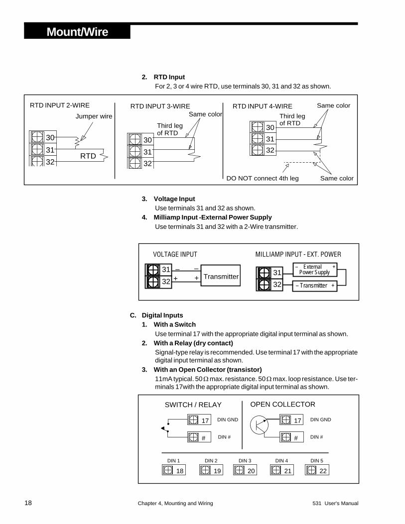
2. RTD InputFor 2, 3 or 4 wire RTD, use terminals 30, 31 and 32 as shown.
3. Voltage InputUse terminals 31 and 32 as shown.
4. Milliamp Input -External Power SupplyUse terminals 31 and 32 with a 2-Wire transmitter.
C. Digital Inputs1. With a Switch
Use terminal 17 with the appropriate digital input terminal as shown.2. With a Relay (dry contact)
Signal-type relay is recommended. Use terminal 17 with the appropriatedigital input terminal as shown.
3. With an Open Collector (transistor)11mA typical. 50 Ω max. resistance. 50 Ω max. loop resistance. Use ter-minals 17with the appropriate digital input terminal as shown.
+ –
Transmitter –
+31
32 – Transmitter +
– External + Power Supply 31
32
MILLIAMP INPUT - EXT. POWERVOLTAGE INPUT

Mount/Wire
531 User's Manual Chapter 4, Mounting and Wiring 19
WARNING!DO NOT make any modifications to thefactory setting of output modules 2, 3 and4; this will place the product in an invalidand undefined state.
D. Remote Setpoint IndicatorUse terminals 28 and 29 as shown.
WIRING THE 531 OUTPUTS• Output 1 is available for use as an ALARM or HOST FLAG with installa-
tion of a Mechanical Relay, Solid State Relay (Triac) module, or SSRDrive.
• The 531 is factory configured with an Analog module in Output 2.• The 531 is factory configured with Mechanical Relays in Outputs 3 and 4.• The 531 cannot be wired for retransmission.• A small PC board fits over rear terminals 5 to 8 and 13 to 16.
These instructions explain proper wiring of the 531 for any output module. Ifyou do not know which module(s) have been installed in your station,compare the number on the product label with the Order Code on page 3.To add or change position of jumper 1 or output module 1, refer to Chapter 3.A. CV Output
• Use terminals 5 and 8 for CV Output as shown in Figure 4.4.• Use terminals 14 and 15 for CV Input.
B. Mechanical Relay Output• Use terminals 3 and 4 as shown in Figure 4.4.• Jumper J1 can be set to normally open (NO) or normally closed (NC)
as desired.C. Solid State Relay (Triac) Output
• Use terminals 3 and 4 as shown in Figure 4.4.• Jumper J1 must be set to normally open (NO).
D. DC Logic (SSR Drive) Output• Use terminals 3 and 4 as shown in Figure 4.4.• Jumper J1 must be set to normally open (NO).
3
4
_
+Load
_
+
DC LOGIC (SSR DRIVE)
3
4
Line Power
Load
Recommend use of both MOV and snubber
MECHANICAL RELAY
3
4
Line Power
Load
-
+
-+
Recommend use of both MOV and snubber
SSR (TRIAC)
5
6
_
+
CV
CV OUTPUT
7
8
29
28–
+–+ Source
Figure 4.4Output Wiring for the 531

20 Chapter 4, Mounting and Wiring 531 User's Manual
Mount/Wire
PCor other host
531 Terminals
RS-485 port
Twisted, shieldedTo "Comm –" terminal of next Powers device
To "Comm +" terminal of next Powers deviceComm +
Comm Ð 26
27
The shield needs to be connected continuously but only tied to
one ground at the host. Failure to follow these proper wiring practices
could result in transmission errors and other communication problems.
Use a 60Ω to 100Ω terminating resistor
connected to the two data terminals
of the final device on the line.
Figure 4.5Serial Communications Terminals
WIRING FOR SERIAL COMMUNICATIONSYou must have this option installed on your 531 in order to use serial commu-nications. Refer to Figure 4.5.• Use a twisted shielded pair of wires to connect the host and field units.
Belden #9414 foil shield has superior noise rejection characteristics. #8441braid shield 22-gauge wire has more flexibility.
• The maximum recommended length of the RS 485 line is 4000 ft.• Termination resistors are required at the host and the last device on the
line. Some RS 485 cards/converters already have a terminating resistor.We recommend using RS-232/RS-485 converter (prod. no. 500-485).
WHERE TO GO NEXTFor a step-by-step guide on setting up the software features for your control-ler, see Chapter 5.
531 User's Manual Chapter 5, Software Configuration 21
Software
CHAPTER 5
SOFTWARE CONFIGURATION
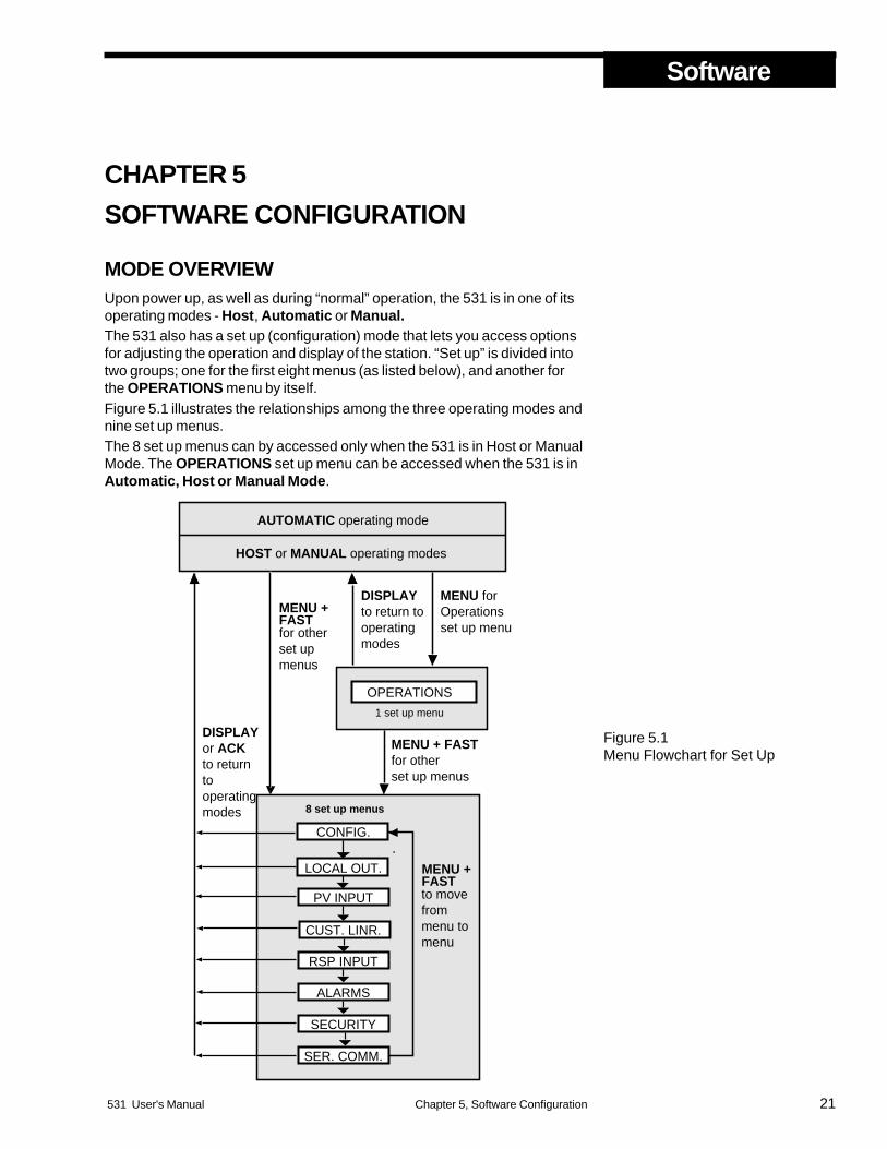
MODE OVERVIEWUpon power up, as well as during “normal” operation, the 531 is in one of itsoperating modes - Host, Automatic or Manual.The 531 also has a set up (configuration) mode that lets you access optionsfor adjusting the operation and display of the station. “Set up” is divided intotwo groups; one for the first eight menus (as listed below), and another forthe OPERATIONS menu by itself.Figure 5.1 illustrates the relationships among the three operating modes andnine set up menus.The 8 set up menus can by accessed only when the 531 is in Host or ManualMode. The OPERATIONS set up menu can be accessed when the 531 is inAutomatic, Host or Manual Mode.
MENU forOperationsset up menu
CONFIG.
LOCAL OUT.
PV INPUT
RSP INPUT
ALARMS
SECURITY
CUST. LINR.
AUTOMATIC operating mode
HOST or MANUAL operating modes
DISPLAY to return tooperating modes
for otherset up menus
SER. COMM.
DISPLAYor ACKto return to operatingmodes
to move frommenu to menu
8 set up menus
OPERATIONS
1 set up menu
MENU +FAST
MENU +FAST
MENU + FASTfor otherset up menus
Figure 5.1Menu Flowchart for Set Up
Software
22 Chapter 5, Software Configuration 531 User's Manual
MENUSA menu is a group of configuration control parameters. While in these set upmenus, the name of the menu will appear in the 2nd display. The names of thedifferent parameters within that menu group will then replace the menu namein the 2nd display. The values/options for each parameter will then appear inthe 3rd display. Figure 5.1 displays the parts of the menu as used by this manual.The (possible) menus for the 531 are:• OPERATIONS To set up special PID control parameters and make
adjustments to the transition functions (among operating modes)of the station.
• CONFIG. To configure the input and output hardware assignments.• LOCAL OUT. To configure the local output control.• PV INPUT To configure the process variable.• CUST. LINR To configure the custom linearization curve for the
process variable.• RSP INPUT To configure the remote set point.• ALARMS To configure alarms.• SECURITY To configure the security function.• SER. COMM. To configure serial communications.
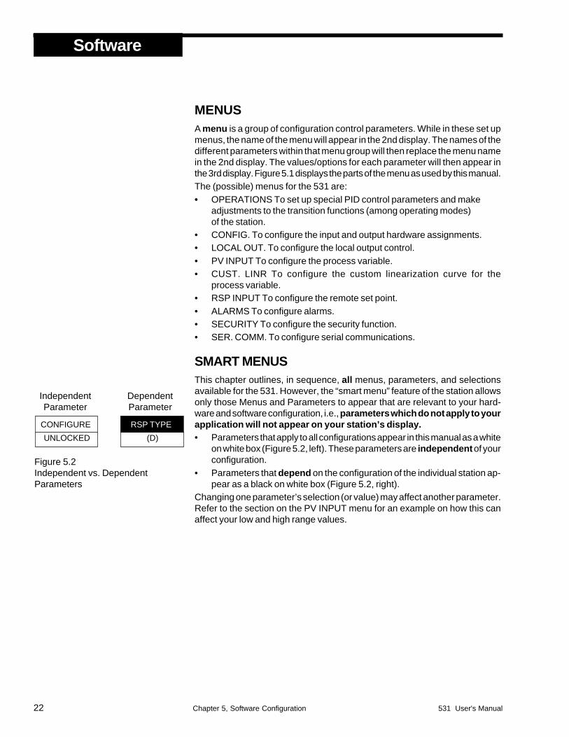
SMART MENUSThis chapter outlines, in sequence, all menus, parameters, and selectionsavailable for the 531. However, the “smart menu” feature of the station allowsonly those Menus and Parameters to appear that are relevant to your hard-ware and software configuration, i.e., parameters which do not apply to yourapplication will not appear on your station’s display.• Parameters that apply to all configurations appear in this manual as a white
on white box (Figure 5.2, left). These parameters are independent of yourconfiguration.
• Parameters that depend on the configuration of the individual station ap-pear as a black on white box (Figure 5.2, right).
Changing one parameter’s selection (or value) may affect another parameter.Refer to the section on the PV INPUT menu for an example on how this canaffect your low and high range values.
Figure 5.2Independent vs. DependentParameters
CONFIGURE
UNLOCKED
RSP TYPE
(D)
IndependentParameter
DependentParameter

531 User's Manual Chapter 5, Software Configuration 23
Software
SOFTWARE CONFIGURATION PROCEDURESOn the bottom of each page is a guide to the keypad, to use during yourconfiguration.To access the 8 set up menus1. Hold down the FAST key and press MENU. (see Figure 5.3). The MENU
key will illuminate. The first Menu, CONFIG., appears alone in the 2nddisplay.
2. Press FAST + MENU to advance to the next menu. The menu name willappear in the 2nd display.
To access the OPERATIONS set up menu1. Press MENU. The MENU key will illuminate. OPERATION will appear in
the 2nd display.To advance through parameters and select a parameter value1. When you reach your chosen menu, press MENU. The first parameter of
this menu appears in the 2nd display, replacing the menu name. The firstvalues/selection for the particular parameter appears in the 3rd display.
2. Press or , with or without the FAST key.3. Press MENU to advance to next parameter.To return to operating mode from configuration1. Press the DISPLAY key. The station will return to the operating mode.
WARNING!!Scrolling through the choices to make selections will affect the opera-tion of the instrument since changes to parameter selections occur in"real time" or immediately.
DO NOT MAKE ANY CHANGES DURING ON LINE OPERATION!
Escape to operating mode Next parameter Next menu Next value orFAST MENU+MENUDISPLAY
Figure 5.3Keys to Enter and Move through SetUp Mode
MENU FAST
MENU

Software
24 Chapter 5, Software Configuration 531 User's Manual

531 User's Manual Chapter 5, Software Configuration 25
Software
Escape to operating mode Next parameter Next menu Next value orMENU FAST DISPLAY MENU+
CONFIG
LOST HOST
AUTO.LOCAL
HOST.RESTR.
HOST
AUTO.LOCAL
GUIDE TO SET UP PARAMETERSOnly parameters and selections relevant to your hardware and other softwareselections will appear on your station.
• Parameter Value(R) Parameter Range(D) Default Setting
CONFIG.
For configuring the input and output hardware assignments.
1. LOST HOSTSelects the type of local backup if 531 loses the host CV signal.• MAN. OUT1 Switch to Manual Mode, use preset output MAN. OUT1• MAN. OUT2 Switch to Manual Mode, use preset output MAN. OUT2• MAN. LAST Go to Manual Mode using the last known output(D) AUTO.LOCAL Go to Automatic (PID)Mode• AUTO.TRACK Go to Automatic (PID)Mode using last PV as the local SP
2. HOST.RESTR.Selects the 531 mode upon host CV restoration.• LOCAL Remain in Manual (or Automatic) Mode(D) HOST MODE Go to Host Mode
3. CONTACT 1Defines the operation of the 1st digital input.• MAN. LAST Switch to Local Manual Mode, use last output• MAN. OUT1 Switch to Manual Mode, use preset output MAN. OUT1• MAN. OUT2 Switch to Manual Mode, use preset output MAN. OUT2• ALARM ACK. Acknowledge alarms• UP KEY Remote key• DOWN KEY Remote key• COMM.ONLY Make status readable through communications• DISP. KEY Remote DISPLAY key• MENU KEY Remote MENU key• FAST KEY Remote FAST key• RST.INHBT. Inhibits PID reset action• REMOTE SP Selects the Remote SP for Automatic Mode• LOCAL SP Selects the Local SP for Automatic Mode(D) AUTO.LOCAL Go to Automatic Mode• HOST MODE Go to Host Mode• WATCHDOG Monitors the Host device for failure.
NOTE:Refer to Chapter 6 for more on theWatchdog Monitor.
CONTACT1

Escape to operating mode Next parameter Next menu Next value
Software
26 Chapter 5, Software Configuration 531 User's Manual
orMENU FAST DISPLAY MENU+
CONFIG
CONTACT 2
MAN.LAST
4. CONTACT 2Defines the operation of the 2nd digital input.(D) MAN. LAST Switch to Local Manual Mode, use last output• MAN. OUT1 Switch to Manual Mode, use preset output MAN. OUT1• MAN. OUT2 Switch to Manual Mode, use preset output MAN. OUT2• ALARM ACK. Acknowledge alarms• UP KEY Remote key• DOWN KEY Remote key• COMM.ONLY Make status readable through communications• DISP. KEY Remote DISPLAY key• MENU KEY Remote MENU key• FAST KEY Remote FAST key• RST.INHBT. Inhibits PID reset action• REMOTE SP Selects the Remote SP for Automatic Mode• LOCAL SP Selects the Local SP for Automatic Mode• AUTO.LOCAL Go to Automatic Mode• HOST MODE Go to Host Mode• WATCHDOG Monitors the Host device for failure
5. CONTACT 3Defines the operation of the 3rd digital input.• MAN. LAST Switch to Local Manual Mode, use last output• MAN. OUT1 Switch to Manual Mode, use preset output MAN. OUT1• MAN. OUT2 Switch to Manual Mode, use preset output MAN. OUT2• ALARM ACK. Acknowledge alarms• UP KEY Remote key• DOWN KEY Remote key• COMM.ONLY Make status readable through communications• DISP. KEY Remote DISPLAY key• MENU KEY Remote MENU key• FAST KEY Remote FAST key• RST.INHBT. Inhibits PID reset action• REMOTE SP Selects the Remote SP for Automatic Mode(D) LOCAL SP Selects the Local SP for Automatic Mode• AUTO.LOCAL Go to Automatic Mode• HOST MODE Go to Host Mode• WATCHDOG Monitors the Host device for failure.
CONTACT 3
LOCAL SP

531 User's Manual Chapter 5, Software Configuration 27
Software
Escape to operating mode Next parameter Next menu Next value orMENU FAST DISPLAY MENU+
CONFIG
6. CONTACT 4Defines the operation of the 4th digital input.• MAN. LAST Switch to Local Manual Mode, use last output• MAN. OUT1 Switch to Manual Mode, use preset output MAN. OUT1• MAN. OUT2 Switch to Manual Mode, use preset output MAN. OUT2(D) ALARM ACK. Acknowledge alarms• UP KEY Remote key• DOWN KEY Remote key• COMM.ONLY Make status readable through communications• DISP. KEY Remote DISPLAY key• MENU KEY Remote MENU key• FAST KEY Remote FAST key• RST.INHBT. Inhibits PID reset action• REMOTE SP Selects the Remote SP for Automatic Mode• LOCAL SP Selects the Local SP for Automatic Mode• AUTO.LOCAL Go to Automatic Mode• HOST MODE Go to Host Mode• WATCHDOG Monitors the Host device for failure.
7. CONTACT 5Defines the operation of the 5th digital input.• MAN. LAST Switch to Local Manual Mode, use last output• MAN. OUT1 Switch to Manual Mode, use preset output MAN. OUT1• MAN. OUT2 Switch to Manual Mode, use preset output MAN. OUT2• ALARM ACK. Acknowledge alarms• UP KEY Remote key• DOWN KEY Remote key• COMM.ONLY Make status readable through communications• DISP. KEY Remote DISPLAY key• MENU KEY Remote MENU key• FAST KEY Remote FAST key• RST.INHBT. Inhibits PID reset action• REMOTE SP Selects the Remote SP for Automatic Mode• LOCAL SP Selects the Local SP for Automatic Mode• AUTO.LOCAL Go to Automatic Mode(D) HOST MODE Go to Host Mode• WATCHDOG Monitors the Host device for failure.
8. WATCHDOGDefines function of the watchdog contact(s) for monitoring the Host.(D) DISABLED• ENABLED
CONTACT 4
ALARM ACK
WATCHDOG
DISABLED
CONTACT 5
HOST MODE

Escape to operating mode Next parameter Next menu Next value
Software
28 Chapter 5, Software Configuration 531 User's Manual
orMENU FAST DISPLAY MENU+
LOCAL OUT.
AUTO.LO.LIM.
0%
AUTO.HI.LIM.
100%
MAN. OUT1
0.0%
MAN. OUT2
100.0%
9. LINE FREQ.Specifies the power source frequency.(D) 60 Hz• 50 Hz
10. OUTPUT 1Defines the function of the 1st output.(D) OFF Deactivates output• ALARM (Digital only)• COMM.ONLY Output addressable only through communications
11. PID.ACTIONSelect the PID control action.• DIRECT(D) REVERSE
12. STN. NAMEAllows you to enter a nine character message to name the station. To use:The first character of the 3rd display will be flashing. Use the and keysto scroll through characters. Press FAST to enter the selection and moveto next digit. Press MENU to advance to next parameter.(D) BYPASSER
LOCAL OUT.
To configure the local output control.
1. AUTO.LO.LIM.Selects how low the Automatic PID output can be adjusted.(R) 0% to 100%(D) 0%
2. AUTO.HI.LIM.Selects how high the Automatic PID output can be adjusted.(R) 0% to 100%(D) 100%
3. MAN. OUT1Selects the Manual Mode preset output #1.(R) –5.0% to 105.0%(D) 0.0%
4 MAN. OUT2Selects the Manual Mode preset output #2.(R) –5.0% to 105.0%(D) 100.0%
PID ACTION
REVERSE
STN. NAME
BYPASSER
LINE FREQ.
60 Hz
OUTPUT 1
OFF
CONFIG.

531 User's Manual Chapter 5, Software Configuration 29
Software
Escape to operating mode Next parameter Next menu Next value orMENU FAST DISPLAY MENU+
5. PWR.UP:MODESelects the power-up mode for the 531.• MANUAL Manual Mode• HOST MODE Host Mode(D) LAST MODE• AUTO.LOCAL Automatic Mode (must have a valid PV signal )
6. MAN. PWR.UPDetermines the output percentage when the 531 powers up in ManualMode .(R) –0.5% to 105%(D) LAST OUT
PV INPUT
For configuring the process variable (PV) input. The whole menu appears onlyif PV indicator is enabled.
1. PV TYPESelects the particular sensor or input range.
PWR.UP:MODE
LAST MODE
PV INPUT
MAN. PWR.UP
LAST OUT
PV TYPE
(D)FOR RTD INPUT:(D) DIN RTD• JIS RTD• SAMA RTD
FOR T/C INPUT:(D) J T/C• E T/C• K T/C• B T/C• N T/C• R T/C• S T/C• T T/C• W T/C• W5 T/C• PLAT.II T/C
DECIMAL
XXXXX
DEG. F/C/K
FAHR.
LOCAL OUT.
2. DEG. F/C/KSelects the temperature unit if using a thermocouple or RTD.(D) FAHR.• CELSIUS• KELVIN
3. DECIMALSpecifies the decimal point position.FOR V/MA INPUT: FOR RTD INPUT:(D) XXXXX (D) XXXXX• XXXX.X • XXXX.X• XXX.XX• XX.XXX• X.XXXX
FOR VOLTAGE INPUT:(D) 1-5 V• 0-5 V• 0-10 mV• 0-30 mV• 0-60 mV• 0-100 mV• +/–25 mV
FOR CURRENT (MA) NPUT:(D) 4-20 mA• 0-20 mA
Escape to operating mode Next parameter Next menu Next value
Software
30 Chapter 5, Software Configuration 531 User's Manual
orMENU FAST DISPLAY MENU+
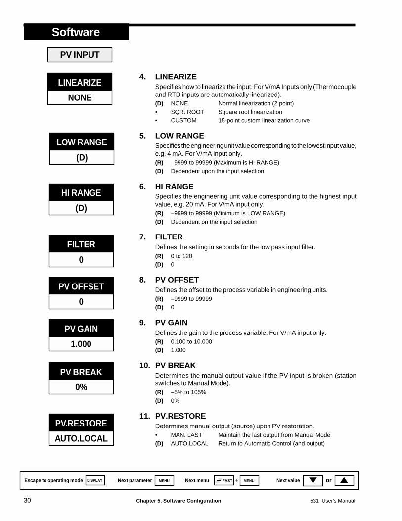
LINEARIZE
NONE
4. LINEARIZESpecifies how to linearize the input. For V/mA Inputs only (Thermocoupleand RTD inputs are automatically linearized).(D) NONE Normal linearization (2 point)• SQR. ROOT Square root linearization• CUSTOM 15-point custom linearization curve
5. LOW RANGESpecifies the engineering unit value corresponding to the lowest input value,e.g. 4 mA. For V/mA input only.(R) –9999 to 99999 (Maximum is HI RANGE)(D) Dependent upon the input selection
6. HI RANGESpecifies the engineering unit value corresponding to the highest inputvalue, e.g. 20 mA. For V/mA input only.(R) –9999 to 99999 (Minimum is LOW RANGE)(D) Dependent on the input selection
7. FILTERDefines the setting in seconds for the low pass input filter.(R) 0 to 120(D) 0
8. PV OFFSETDefines the offset to the process variable in engineering units.(R) –9999 to 99999(D) 0
9. PV GAINDefines the gain to the process variable. For V/mA input only.(R) 0.100 to 10.000(D) 1.000
10. PV BREAKDetermines the manual output value if the PV input is broken (stationswitches to Manual Mode).(R) –5% to 105%(D) 0%
11. PV.RESTOREDetermines manual output (source) upon PV restoration.• MAN. LAST Maintain the last output from Manual Mode(D) AUTO.LOCAL Return to Automatic Control (and output)
PV INPUT
HI RANGE
(D)
FILTER
0
PV OFFSET
0
PV GAIN
1.000
PV BREAK
0%
PV.RESTORE
AUTO.LOCAL
LOW RANGE
(D)

531 User's Manual Chapter 5, Software Configuration 31
Software
Escape to operating mode Next parameter Next menu Next value orMENU FAST DISPLAY MENU+
CUST. LINR.
Defines a custom linearization curve for the process variable input. Thecurve may be either ever increasing or ever decreasing. However, plateausor flat spots (adjacent points with the same PV) are allowable.The curve has 15 points. Points 1 and 15 are fixed to the low and high end ofthe input range (respectively) and only require you to set a correspondingPV value. Points 2 through 14 (the X points) require you to set both the inputand PV values.NOTE: Changing the PV TYPE parameter in the PV INPUT menu clears thecustom linearization curve and resets the linearization type to NORMAL.You must again select CUSTOM for the linearization type and reenter yourcurve, adjusted for the new input type.
1. 1ST. INPUTSpecifies the input signal for to the first point.(D) The low end of the appropriate input range (e.g. 4.00 mA)
2. 1ST. PVSpecifies the engineering unit value for to the first point.(R) –9999 to 99999(D) 0
3. XTH. INPUTSpecifies the input signal for to the XTH point (X is 2 to 14) .(R) Any value greater than the first input(D) The low end of the appropriate input range (e.g. 4.00 mA)
4. XTH. PVSpecifies the engineering unit value for to the XTH point (X is 2 to 14).(R) –9999 to 99999(D) 0
You do not have to use all 15 points. Whenever the XTH INPUT becomesthe high end of the input range, that will be the last point in the table.
5. 15TH. INPT.Specifies the input signal for to the 15th point.(R) –9999 to 99999(D) The high end of the appropriate input range (e.g. 20.00 mA)
6. 15TH. PVSpecifies the engineering unit value for to the 15th point.(R) –9999 to 99999(D) 0
CUST. LINR.
1ST. INPUT
(D)
1ST. PV
0
XTH. INPUT
(D)
XTH. PV
0
15TH. INPT.
(D)
15TH. PV
0

Escape to operating mode Next parameter Next menu Next value
Software
32 Chapter 5, Software Configuration 531 User's Manual
orMENU FAST DISPLAY MENU+
RSP INPUT
For configuring the remote setpoint (if enabled).
1. RSP TYPESpecifies type of input signal that will be used for the setpoint indicator.IF THE JUMPER IS IN THE MA POSITION IF THE JUMPER IS IN THE V POSITION:(D) 4-20 mA (D) 1-5 V• 0-20 mA • 0-5 V
2. RSP LOWSpecifies the engineering unit value corresponding to the lowest setpointindicator input value, e.g. 4 mA.(R) –9999 to 99999(D) 0
3. RSP HIGHSpecifies the engineering unit value corresponding to the highest setpointindicator input value, e.g. 20 mA.(R) –9999 to 99999(D) 1000
4. RSP.OFFSETDefines the offset to the remote setpoint in engineering units.(R) –9999 to 99999(D) 0
5. RSP GAINDefines the gain to the remote setpoint.(R) 0.100 to 10.000(D) 1.000
6. TRACKINGDetermines whether or not the local SP will track the remote SP (upon RSPbreak, or switch to local from remote SP).(D) YES• NO
7. RSP.RESTOR.Determines RSP (source) upon RSP input restoration.• LOCAL SP(D) REMOTE SP
RSP INPUT
RSP TYPE
(D)
TRACKING
YES
RSP GAIN
1.000
RSP OFFSET
0
RSP HIGH
1000
RSP.RESTOR.
REMOTE SP
RSP LOW
0
531 User's Manual Chapter 5, Software Configuration 33
Software
Escape to operating mode Next parameter Next menu Next value orMENU FAST DISPLAY MENU+
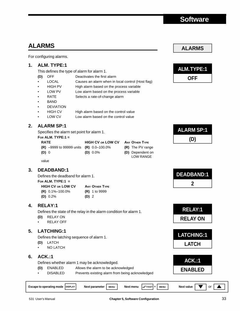
ALARMS
For configuring alarms.
1. ALM. TYPE:1This defines the type of alarm for alarm 1.(D) OFF Deactivates the first alarm• LOCAL Causes an alarm when in local control (Host flag)• HIGH PV High alarm based on the process variable• LOW PV Low alarm based on the process variable• RATE Selects a rate-of-change alarm• BAND• DEVIATION• HIGH CV High alarm based on the control value• LOW CV Low alarm based on the control value
2. ALARM SP:1Specifies the alarm set point for alarm 1.FOR ALM. TYPE:1 =
RATE HIGH CV OR LOW CV ANY OTHER TYPE
(R) –9999 to 99999 units (R) 0.0–100.0% (R) The PV range(D) 0 (D) 0.0% (D) Dependent on
LOW RANGEvalue
3. DEADBAND:1Defines the deadband for alarm 1.FOR ALM. TYPE:1 =
HIGH CV OR LOW CV ANY OTHER TYPE
(R) 0.1%–100.0% (R) 1 to 9999(D) 0.2% (D) 2
4. RELAY:1Defines the state of the relay in the alarm condition for alarm 1.(D) RELAY ON• RELAY OFF
5. LATCHING:1Defines the latching sequence of alarm 1.(D) LATCH• NO LATCH
6. ACK.:1Defines whether alarm 1 may be acknowledged.(D) ENABLED Allows the alarm to be acknowledged• DISABLED Prevents existing alarm from being acknowledged
ALARMS
ALM. TYPE:1
OFF
ALARM SP:1
(D)
DEADBAND:1
2
RELAY:1
RELAY ON
LATCHING:1
LATCH
ACK.:1
ENABLED
Escape to operating mode Next parameter Next menu Next value
Software
34 Chapter 5, Software Configuration 531 User's Manual
orMENU FAST DISPLAY MENU+
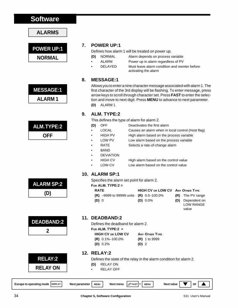
7. POWER UP:1Defines how alarm 1 will be treated on power up.(D) NORMAL Alarm depends on process variable• ALARM Power up in alarm regardless of PV• DELAYED Must leave alarm condition and reenter before
activating the alarm
8. MESSAGE:1Allows you to enter a nine character message associated with alarm 1. Thefirst character of the 3rd display will be flashing. To enter message, pressarrow keys to scroll through character set. Press FAST to enter the selec-tion and move to next digit. Press MENU to advance to next parameter.(D) ALARM 1
9. ALM. TYPE:2This defines the type of alarm for alarm 2.(D) OFF Deactivates the first alarm• LOCAL Causes an alarm when in local control (Host flag)• HIGH PV High alarm based on the process variable• LOW PV Low alarm based on the process variable• RATE Selects a rate-of-change alarm• BAND• DEVIATION• HIGH CV High alarm based on the control value• LOW CV Low alarm based on the control value
10. ALARM SP:1Specifies the alarm set point for alarm 2.FOR ALM. TYPE:2 =
RATE HIGH CV OR LOW CV ANY OTHER TYPE
(R) –9999 to 99999 units (R) 0.0–100.0% (R) The PV range(D) 0 (D) 0.0% (D) Dependent on
LOW RANGEvalue
11. DEADBAND:2Defines the deadband for alarm 2.FOR ALM. TYPE:2 =
HIGH CV OR LOW CV ANY OTHER TYPE
(R) 0.1%–100.0% (R) 1 to 9999(D) 0.2% (D) 2
12. RELAY:2Defines the state of the relay in the alarm condition for alarm 2.(D) RELAY ON• RELAY OFF
ALM. TYPE:2
OFF
ALARM SP:2
(D)
DEADBAND:2
2
RELAY:2
RELAY ON
MESSAGE:1
ALARM 1
ALARMS
POWER UP:1
NORMAL

531 User's Manual Chapter 5, Software Configuration 35
Software
Escape to operating mode Next parameter Next menu Next value orMENU FAST DISPLAY MENU+
13. LATCHING:2Defines the latching sequence of alarm 2.(D) LATCH• NO LATCH
14. ACK.:2Defines whether alarm 2 may be acknowledged.(D) ENABLED Allows the alarm to be acknowledged• DISABLED Prevents the alarm acknowledgment while alarm
condition exists.
15. POWER UP:2Defines how alarm 2 will be treated on power up.(D) NORMAL Alarm depends on process variable• ALARM Always power up in alarm regardless of process
variable• DELAYED Must leave alarm condition and reenter before
activating the alarm
16. MESSAGE:2Allows you to enter a nine character message associated with alarm 2. Thefirst character of the 3rd display will be flashing. To enter message, pressarrow keys to scroll through character set. Press FAST key to enter theselection and move to next digit. Press MENU key to advance to next pa-rameter.(D) ALARM 2
17. RATE TIMEDefines the time period (in seconds) over which a rate-of-change alarmcondition will be determined.(R) 1 to 3600(D) 5
SECURITY
For configuring the security function.
1. SEC. CODEDefines security code for temporarily unlocking the station.(R) –9999 to 99999(D) 0
2. HOST KEYDefines lockout status of the HOST key (mode changes via the HOST key).(D) UNLOCKED• LOCKED
POWER UP:2
NORMAL
ALARMS
MESSAGE:2
ALARM 2
RATE TIME
5
SEC. CODE
0
SECURITY
HOST KEY
UNLOCKED
LATCHING:2
LATCH
ACK.:2
ENABLED

Escape to operating mode Next parameter Next menu Next value
Software
36 Chapter 5, Software Configuration 531 User's Manual
orMENU FAST DISPLAY MENU+
3. MAN. KEYDefines lockout status of the MANUAL key (mode changes via theMANUAL key).(D) UNLOCKED• LOCKED
4. MAN. OUTDefines lockout status of the changes to the local output (via the and keys).(D) UNLOCKED• LOCKED
5. LOCAL SPDefines lockout status of the changes to the local setpoint (via the and keys).(D) UNLOCKED• LOCKED
6. ALARM ACK.Defines lockout status of the ACK key (alarm acknowledgment).(D) UNLOCKED• LOCKED
7. OPERATIONDefines lockout status of the OPERATION menu parameters.(D) UNLOCKED• LOCKED
8. CONFIGUREDefines lockout status of the other 8 configuration parameters.(D) UNLOCKED• LOCKED
SER. COMM.
For configuring the serial communications features.
1. STATIONDefines the unit’s station address.(R) 1 to 99• OFF Disables the communications function.(D) 1
SECURITY
LOCAL SP
UNLOCKED
OPERATION
UNLOCKED
ALARM ACK
UNLOCKED
CONFIGURE
UNLOCKED
SER. COMM.
STATION
1
MAN. KEY
UNLOCKED
MAN. OUT
UNLOCKED

531 User's Manual Chapter 5, Software Configuration 37
Software
Escape to operating mode Next parameter Next menu Next value orMENU FAST DISPLAY MENU+
2. BAUD RATEDefines the baud rate.• 1200 BPS• 2400 BPS• 4800 BPS(D) 9600 BPS• 19200 BPS
3. CRCDefines whether CRC (cyclic redundancy check) is being calculated.(D) YES• NO
OPERATION
For modifications to the transition functions. Use the same PID parametersas your HOST device.
1. PROP. BANDDefines the proportional band for the PID set.(R) 0.1% to 999.0%(D) 50.0%
2. RESETDefines the integral time for the PID set.(R) 1 to 9999 seconds/repeat(D) 30
3. RATEDefines the derivative time for the PID set.(R) 0 to 600 seconds(D) 1
4. LOADLINEDefines the loadline (manual reset) for the PID set.(R) 0% to 100%(D) 0%
5. SP SOURCESelects a local or remote setpoint.(D) LOCAL SP• REMOTE SP (only for 2nd input V or mA)
PROP. BAND
50.0%
RESET
20
OPERATION
RATE
1
LOADLINE
0%
SP SOURCE
LOCAL SP
CRC
YES
BAUD RATE
9600
SER. COMM.

Escape to operating mode Next parameter Next menu Next value
Software
38 Chapter 5, Software Configuration 531 User's Manual
orMENU FAST DISPLAY MENU+
6. MAN. RAMPDetermines ramping value for output to a defined Manual output value(MAN. OUT1, MAN. OUT2 or PV BREAK) upon transfer to Manual Mode.(R) 0.1% to 999.9% per minute(D) OFF
7. HOST RAMPDetermines ramping value for output to the Host Mode CV value, upontransfer to Host Mode.(R) 0.1% to 999.9% per minute(D) OFF
HOST RAMP
OFF
MAN. RAMP
OFF
OPERATION

Software
531 User's Manual Chapter 5, Software Configuration 39
CONFIG.For configuring the input and output hardware assignments.
1. LOST HOST Selects the type of local backup when host CV breaks.
2. HOST. RESTR. Selects the 531 mode upon host CV restoration.
3. CONTACT 1 Defines the operation of the 1st digital input.
4. CONTACT 2 Defines the operation of the 2nd digital input.
5. CONTACT 3 Defines the operation of the 3rd digital input.
6. CONTACT 4 Defines the operation of the 4th digital input.
7. CONTACT 5 Defines the operation of the 5th digital input.
8. WATCHDOG Defines function of Host watchdog monitor.
9. LINE FREQ. Specifies the power source frequency.
10. OUTPUT 1 Defines the function of the 1st output.
11. PID.ACTION Select the PID control action.
12. STN. NAME Specifies a nine character message to name the station.
NOTE:You may want to photocopy thesepages instead of entering the valueson the master sheets.
PARAMETER VALUE CHARTSRecord the values for the various configuration menu parameters on the chartsin this section.
LOCAL OUT.To configure the local output control.
1. AUTO.LO.LIM. Selects low limit for adjusting the Automatic PID output.
2. AUTO.HI.LIM. Selects high limit for adjusting the Automatic PID output.
3. MAN. OUT1 Selects the Manual Mode preset output #1.
4 MAN. OUT2 Selects the Manual Mode preset output #2.
5. PWR.UP:MODE Selects the power-up mode for the 531.
6. MAN. PWR.UP Determines output % for in Manual Mode power up.
Software
40 Chapter 5, Software Configuration 531 User's Manual
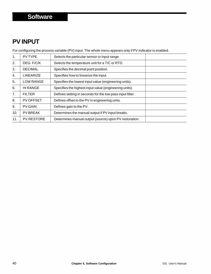
PV INPUTFor configuring the process variable (PV) input. The whole menu appears only if PV indicator is enabled.
1. PV TYPE Selects the particular sensor or input range.
2. DEG. F/C/K Selects the temperature unit for a T/C or RTD.
3. DECIMAL Specifies the decimal point position.
4. LINEARIZE Specifies how to linearize the input.
5. LOW RANGE Specifies the lowest input value (engineering units).
6. HI RANGE Specifies the highest input value (engineering units).
7. FILTER Defines setting in seconds for the low pass input filter.
8. PV OFFSET Defines offset to the PV in engineering units.
9. PV GAIN Defines gain to the PV.
10. PV BREAK Determines the manual output if PV input breaks.
11. PV.RESTORE Determines manual output (source) upon PV restoration.

Software
531 User's Manual Chapter 5, Software Configuration 41
CUST. LINR.Defines a custom linearization curve for the process variable input.
1. 1ST. INPUT Specifies the input signal for the 1st point.
2. 1ST. PV Specifies the engineering unit value for the 1st point.
3. 2ND. INPUT Specifies the input signal for the 2nd point.
4. 2ND. PV Specifies the engineering unit value for the 2nd point.
5. 3RD. INPUT Specifies the input signal for the 3rd point.
6. 3RD. PV Specifies the engineering unit value for the 3rd point.
7. 4TH. INPUT Specifies the input signal for the 4th point.
8. 4TH. PV Specifies the engineering unit value for the 4th point.
9. 5TH. INPUT Specifies the input signal for the 5th point.
10. 5TH. PV Specifies the engineering unit value for the 5th point.
11. 6TH. INPUT Specifies the input signal for the 6th point.
12. 6TH. PV Specifies the engineering unit value for the 6th point.
13. 7TH. INPUT Specifies the input signal for the 7th point.
14. 7TH. PV Specifies the engineering unit value for the 7th point.
15. 8TH. INPUT Specifies the input signal for the 8th point.
16. 8TH. PV Specifies the engineering unit value for the 8th point.
17. 9TH. INPUT Specifies the input signal for the 9th point.
18. 9TH. PV Specifies the engineering unit value for the 9th point.
19. 10TH. INPT. Specifies the input signal for the 10th point.
20. 10TH. PV Specifies the engineering unit value for the 10th point.
21. 11TH. INPT. Specifies the input signal for the 11th point.
22. 11TH. PV Specifies the engineering unit value for the 11th point.
23. 12TH. INPT. Specifies the input signal for the 12th point.
24. 12TH. PV Specifies the engineering unit value for the 12th point.
25. 13TH. INPT. Specifies the input signal for the 13th point.
26. 13TH. PV Specifies the engineering unit value for the 13th point.
27. 14TH. INPT. Specifies the input signal for the 14th point.
28. 14TH. PV Specifies the engineering unit value for the 14th point.
29. 15TH. INPT. Specifies the input signal for the 15th point.
30. 15TH. PV Specifies the engineering unit value for the 15th point.

Software
42 Chapter 5, Software Configuration 531 User's Manual
RSP INPUTFor configuring the remote setpoint (if enabled).
1. RSP TYPE Specifies type of input signal for the remote SP.
2. RSP LOW Lowest (engineering unit) value for the remote SP.
3. RSP HIGH Highest (engineering unit) value for the remote SP.
4. RSP.OFFSET Defines the offset to the remote SP in engineering units.
5. RSP GAIN Defines the gain to the remote setpoint.
6. TRACKING Determines whether or not local SP tracks remote SP.
7. RSP.RESTOR. Determines SP (source) upon RSP input restoration.
ALARMSFor configuring alarms.
1. ALM. TYPE:1 Defines the type of alarm for alarm 1.
2. ALARM SP:1 Specifies the alarm set point for alarm 1.
3. DEADBAND:1 Defines the deadband for alarm 1.
4. RELAY:1 Defines the state of the relay for alarm 1.
5. LATCHING:1 Defines the latching sequence of alarm 1.
6. ACK.:1 Defines whether alarm 1 may be acknowledged.
7. POWER UP:1 Defines how alarm 1 will be treated on power up.
8. MESSAGE:1 A nine character message for alarm 1.
9. ALM. TYPE:2 Defines the type of alarm for alarm 2.
10. ALARM SP:2 Specifies the alarm set point for alarm 2.
11. DEADBAND:2 Defines the deadband for alarm 2.
12. RELAY:2 Defines the state of the relay for alarm 2.
13. LATCHING:2 Defines the latching sequence of alarm 2.
14. ACK.:2 Defines whether alarm 2 may be acknowledged.
15. POWER UP:2 Defines how alarm 2 will be treated on power up.
16. MESSAGE:2 A nine character message for alarm 2.
17. RATE TIME Defines the time period for a rate-of-change alarm.

Software
531 User's Manual Chapter 5, Software Configuration 43
SECURITYFor configuring the security function.
1. SEC. CODE Security code for temporarily unlocking the station.
2. HOST KEY Lockout status of the HOST key.
3. MAN. KEY Lockout status of the MANUAL key.
4. MAN.OUT Lockout status of the changes to the local output.
5. LOCAL SP Lockout status of the changes to the local setpoint.
6. ALARM ACK. Lockout status of the ACK key.
7. OPERATION Lockout status of the OPERATION Menu parameters.
8. CONFIGURE Lockout status of the other 8 configuration parameters.
SER. COMM.For configuring the serial communications features.
1. STATION Defines the unit’s station address.
2. BAUD RATE Defines the baud rate.
3. CRC Defines whether CRC is being calculated.
OPERATIONFor modifications to the transition functions. Use the same PID parameters as your HOST device.
1. PROP. BAND Defines the proportional band for the PID set.
2. RESET Defines the integral time for the PID set.
3. RATE Defines the derivative time for the PID set.
4. LOADLINE Defines the loadline (manual reset) for the PID set.
5. SP SOURCE Selects a local or remote setpoint.
6. MAN.RAMP Determines ramping for output to Manual output value.
7. HOST RAMP Determines ramping for output to the Host Mode CV.

Software
44 Chapter 5, Software Configuration 531 User's Manual

531 User's Manual Chapter 6, Applications 45
Applications
Escape to operating mode Next parameter Next menu Next value orMENU FAST DISPLAY MENU+
NOTE:Available capabilities depend uponthe hardware option you specifiedand ordered.
CHAPTER 6531 APPLICATIONSThe 531 has a variety of user-programmable control features and capabilities.This chapter describes how to apply them.
SECTION .............................................................................................................. PAGE531 Operation ................................................................................. 45Alarms ............................................................................................ 46Digital Inputs ................................................................................... 50Watchdog Monitor .......................................................................... 51Process Variable and Setpoint ........................................................ 51Input Linearization .......................................................................... 53Ramp to a Control Value ................................................................. 54Security .......................................................................................... 55Process Variable Reading Correction ............................................. 56Serial Communications ................................................................... 56
531 OPERATIONThe 531 PID Backup Station provides PID based control backup for critical controlloops. It is normally installed between a Host device and final control element.The Host device may be a PLC, DCS or single loop controller (SLC). The finalcontrol element may be a valve actuator, positioning device, power control unitfor an electric heating element, pump or other control device. The control signalmust always be a 4-20mA proportional signal.
Host Mode (Default Mode)• The HOST key is lit.• In Host Mode, the 531 is transparent to the control loop; it passes the control
signal from the Host device without any degradation.• The 531 constantly monitors the CV and uses the last good signal as a potential
CV for the Automatic Mode.• The 531 can be removed from the case without disrupting the Host signal; it
is not a point of failure.• The 531 switches to Host Mode due to:
- Return of the Host signal- Keypad selection- Closure of a digital contact; or- Commands through the RS-485 port.
• Upon return of the Host signal, the 531 can be programmed to- Return control to the Host Mode immediately;- Ramp to the new CV at a predetermined rate; or- Remain in the current mode, where the operator can determine whether
or not the Host signal is valid.• The operator can modify the local SP using the and keys.• The operator can enter all the configuration menus.
NOTE:In this chapter, the followingabbreviations are used:
CV - Control signalSP - Set pointPV - Process variable

46 Chapter 6, Applications 531 User's Manual
Applications
Escape to operating mode Next parameter Next menu Next value orMENU FAST DISPLAY MENU+
Automatic Mode• Neither the HOST nor MANUAL keys are lit.• The 531 switches to Automatic (PID) Mode due to:
- Loss of the Host signal- Keypad selection- Closure of a digital contact; or- Commands through the RS-485 port.
• Upon switching to Automatic Mode, the 531 generates a control signalbased on PID control.
• The 531 executes a bumpless transfer to the new CV while in PID mode(no ramping needed).
• The operator can modify the local SP using the and keys.• The operator can only enter the OPERATION menu (other configuration
menus are disabled).
Manual Mode• The MANUAL key is lit.• The 531 switches to Manual Mode due to:
- Loss of the Host signal and PV input- Keypad selection- Closure of a digital contact; or- Commands through the RS-485 port.
• In Manual Mode, the 531 can go to a predetermined output. The 531 canalso be set to ramp the last Host signal to the new output.
• The operator can modify the CV signal using the and keys.• The operator can modify the local SP using the and keys.• The operator can enter all the configuration menus.
ALARMSThe 531 has 2 alarms available. It indicates alarm conditions by:• Lighting up the alarm icon(s).• Displaying a custom message in the 3rd display• Illuminating the ACK key if the alarm is acknowledgeable.Each alarm can be assigned one of 6 different types. Also, by adding anoutput module, one of the alarms can be tied to a relay output. To assign analarm:1. Press FAST + MENU to toggle to the ALARM menu.2. Press MENU to select the first parameter ALM.TYPE:1 and select its type
(choose one of the following) using the and keys:LOCAL
(Host Flag) If tied to a relay output, a local alarm notifies the Host thatthe 531 has taken over the output in Manual or Automatic mode.You can choose LOCAL for only one of the alarms. Useful when theHost performs logging functions for Statistical Process Control(SPC), or to prevent reset windup.
NOTE:Refer to “Alarm Operation” inChapter 2 for information onoperating alarms.
NOTE:Refer to Chapter 4 for information onwiring for alarms.

531 User's Manual Chapter 6, Applications 47
Applications
Escape to operating mode Next parameter Next menu Next value orMENU FAST DISPLAY MENU+
HIGH PVOccurs when the process variable exceeds the alarm setpoint.
LOW PVOccurs when the process variable goes below the alarm setpoint.
RATEUse to signal an alarm when the PV changes at a rate greater than thatspecified by the alarm setpoint and time base. For example, if you havean alarm setpoint of 10 and a time base of 5 seconds, an alarm occursif the PV changes greater than 10 units in 5 seconds.
BANDCreates a band twice the size of the alarm setpoint [centered] aroundthe control setpoint. Alarm occurs when the process variable travelsoutside of this band. For example, if your control setpoint is 500 and thealarm setpoint is 25, the alarm occurs if the PV travels outside of the 475to 525 range.Alarm is dependent upon retransmission of the control setpoint. As thecontrol setpoint changes, the band centers itself accordingly.
DEVIATIONCreates a band on one side of the control setpoint. Alarm occurs whenthe process variable deviates from the control setpoint by an amountgreater than the alarm setpoint.For example, if the control setpoint is 500 and the alarm setpoint is +50(plus 50), an alarm occurs when the process variable exceeds 550. Ifyour alarm setpoint is –50, the alarm occurs when the process variabledrops below 450.Alarm is dependent upon retransmission of the control setpoint. As thecontrol setpoint changes, the band centers itself accordingly.
HIGH CVOccurs when the control value exceeds the alarm setpoint.
LOW CVOccurs when the control value goes below the alarm setpoint.
3. Press the MENU key to select the second parameter ALM.TYPE:2 and se-lect its type using the s and t keys.Each alarm type (except a LOCAL alarm) has a number of correspondingparameters that must also be set up in the ALARM menu (steps 4 - 11).Press the MENU key to select the rest of the parameters in the ALARM Menu,and choose their values with the and keys.
4. ALARM SP:1 and ALARM SP:2Specifies, in engineering units, the point at which the alarm occurs.For a rate-of-change alarm, it specifies the amount of change that must occurbefore the alarm activates. A negative value specifies a negative rate-of-change.
5. DEADBAND:1 and DEADBAND:2Specifies the range through which the PV must travel before leaving an alarmcondition (see alarm examples at the end of this section).
NOTE:Only those parameters that apply toyour particular alarm type will appearas you toggle through theparameters.
NOTE:The Band and Deviation alarms arenot selectable without a PV and aretransmitted SP signal.
NOTE:The HIGH CV and LOW CV alarms,when selected, operate in both Hostand Local modes.

48 Chapter 6, Applications 531 User's Manual
Applications
Escape to operating mode Next parameter Next menu Next value orMENU FAST DISPLAY MENU+
This prevents frequent alarm oscillation or “chattering” if the process variablehas stabilized around the alarm point.
6. RELAY:1Specifies whether the relay will be on or off. ON means the relay is energized,while OFF means the relay is de-energized when the station is in the alarmcondition.Most applications require the relay to energize. However, limit applications usuallyrequire the relay to de-energize.
7. LATCHING:1 and LATCHING:2If the alarm is latching (YES), the alarm remains active after leaving the alarmcondition unless acknowledged.If the alarm is non-latching (NO) the alarm returns to its non-alarm state whenleaving the alarm condition without being acknowledged.
8. ACK.:1 and ACK.:2ENABLED allows the operator to acknowledge an alarm at any time, even if thecontrol process is still in the alarm condition.DISABLED prevents the operator from acknowledging an alarm while the processis in the alarm condition.When either alarm is available to be acknowledged, the ACK key will beilluminated. If both alarms are acknowledgable, press the ACK key once toacknowledge alarm #1, then a second time for alarm #2. A latching alarm canalways be acknowledged when it is out of the alarm condition.
9. POWER UP:1 and POWER UP:2If you want the controller to always power up in alarm, regardless of the alarmcondition, then select ALARM. This is an excellent way to activate an alarm ifthere has been a power failure.If you never want the controller to power up in alarm, regardless of alarm condition,select DELAYED. The system must leave and reenter the alarm condition beforethe alarm will activate. This is typically used to avoid alarms during start up.If you want the system to power up in alarm only if it is in an alarm condition, selectNORMAL.
10. MESSAGE:1 and MESSAGE:2Allows you to enter a nine character message to display when the respectivealarm is active. The first character of the 3rd display will be flashing. Use and keys to scroll through character set for each character. Press FASTto enter the selection and move to the next digit. Press MENU to advance tonext parameter.
11. RATE TIMEDefines the time period over which a specific change in process variable mustoccur for the rate alarm to be activated. The amount of change is defined by thealarm setpoint. The rate-of-change is defined as the amount of change dividedby the time period. In general, for a given rate-of-change, the shorter the timeperiod, the more sensitive the rate alarm.
NOTE:You can specify whether the relay isNormally Open or Normally Closedwhen configuring the hardware, withjumper selection only for Output 1.

531 User's Manual Chapter 6, Applications 49
Applications
Escape to operating mode Next parameter Next menu Next value orMENU FAST DISPLAY MENU+
Examples:1. If the alarm setpoint is set to 10 and the time base is set to 1 second,
the rate of change is 10 units per second. The process variable wouldonly have to experience a ten unit change over a short period of time.
2. If the alarm setpoint is set to 100 and the time base set to 10, the rate ofchange is also 10 units per second. The PV would require a 100 unitchange over a ten second period.
Notice that Example 1 is more sensitive than Example 2.
Alarm ExamplesA.SP = Alarm Setpoint C.SP = Control Setpoint DB = Deadband PV = Process Variable
TIME
IN ALARMCONDITION
MAYACKNOWLEDGE
RELAYENERGIZED
RELAYDE-ENERGIZED
ICON ON
MUSTACKNOWLEDGETO SHUT OFFICON ANDDE-ENERGIZE RELAY
ICON OFF
NO ALARM
PV
C. DEVIATION ALARM EXAMPLE
LATCHING:1 = LATCHACK.1 = ENABLED
C.SP + A.SP
ALM. TYPE:1 = DEVIATIONRELAY:1 = RELAY ON
PARAMETER SETTINGS:ALARM SP:1 = ( < 0)
DB
C.SP
TIMEALARM
CONDITION
RELAYENERGIZED
RELAYENERGIZED
ICON ON
PV
D. POWER UP ALARM EXAMPLE
ALM. TYPE:1 = HIGH ALM.RELAY:1 = RELAY ON
A.SP
UNIT POWER UP
RELAYENERGIZED
POWER UP:1 = ALARM
ICON ON
DB
MAYACKNOWLEDGE
ICON ON
MAY ACKNOWLEDGE
CANNOTACKNOWLEDGE
PARAMETER SETTINGS:LATCHING:1 = LATCHACK.:1 = DISABLED
TIME
ICON ON
IN ALARMCONDITION
CANNOTACKNOWLEDGE
RELAYDE-ENERGIZED
RELAYENERGIZED
ICON ON
RELAYDE-ENERGIZED
ICON OFF
PV
A. BAND ALARM EXAMPLE
ICON OFF
RELAYENERGIZED
NO ALARMNO ALARM CANNOTACKNOWLEDGE
C.SP +
C.SP
DB
C.SP – A.SP
A.SP
DB
ALM. TYPE:1 = BAND RELAY:1 = RELAY OFF
IN ALARMCONDITION
PARAMETER SETTINGS: LATCHING = NO LATCH ACK.:1 = DISABLED
TIME
ICON OFF
NO ALARM
IN ALARMCONDITION
MAYACKNOWLEDGE
RELAYENERGIZED
RELAYDE-ENERGIZED
ICON ON
RELAYDE-ENERGIZED
ICON OFF
NO ALARM
PV
B. HIGH PROCESS VARIABLE ALARM EXAMPLE
ALM. TYPE:1 = HIGH ALRM.RELAY:1 = RELAY ON
DBA.SP
LATCHING = NO LATCHACK.:1 = ENABLED
PARAMETER SETTINGS:
Figure 6.1Alarm Examples
50 Chapter 6, Applications 531 User's Manual
Applications
Escape to operating mode Next parameter Next menu Next value orMENU FAST DISPLAY MENU+
NOTE:To verify your hardwareconfiguration, check your productlabel on top of the 531, and compareit to the order code in Chapter 1.
DIGITAL INPUTSThis optional feature is only available if ordered originally from the factory. For aset of 5 digital inputs can be ordered, order Product #531 -xxxxxxDx00.If more than one digital input is closed, then the last one closed generally haspriority over the others.A closed digital input may be overridden by: another digital input, a keyboardoperation, or an automatic function. A closed digital input that was overriddenmust be opened, in order to be “re-armed”.If one digital input is closed and selects LOCAL, and then REMOTE is keyboardselected, the keyboard selection takes precedence.1. Press FAST + MENU to toggle to the CONFIG. menu2. Press MENU to access first parameter, CONTACT:1. Use and to toggle
to the desired function (choose one of the following):MAN. LAST
Contact closure switches the station to Manual Mode using the last outputvalue.
MAN. OUT1Contact closure switches the station to Manual Mode using the MAN.OUT1value.
MAN. OUT2Contact closure switches the station to Manual Mode using the MAN.OUT2value.
ALARM ACK.Contact closure acknowledges all active alarms. The digital input mustbe opened before it is “re-armed.” If the input remains closed, it will notcontinue to immediately acknowledge alarms as they become active.
UP KEY and DOWN KEYContact closure mimics the and keys. If the station is mountedbehind a window, this digital input allows you to use momentary contactpush button to change the station’s output.
COMM. ONLYContact closure renders digital input status readable throughcommunications. It will have no effect on the functions of the station itself.
DISP. KEYContact closure mimics the DISPLAY key.
MENU KEYContact closure mimics the FAST key.
FAST KEYContact closure mimics the FAST key.
RST. INHBT.Contact closure inhibits local PID reset action.
REMOTE SPContact closure selects the remote setpoint for use in Automatic Mode.

531 User's Manual Chapter 6, Applications 51
Applications
Escape to operating mode Next parameter Next menu Next value orMENU FAST DISPLAY MENU+
LOCAL SPContact closure selects the local setpoint for use in Automatic Mode.
AUTO.LOCALContact closure switches the station to Automatic Mode.
HOST MODEContact closure switches the station to Host Mode.
WATCHDOGContact closure activates the watchdog monitor.
2. Press MENU to access contact parameters, CONTACT:2, CONTACT:3,CONTACT:4, and CONTACT:5. Use the and keys to toggle to the desiredfunction for these as well.
WATCHDOG MONITORThis feature is only available with the factory installed five digital inputs.The 531 normally uses the presence of the CV for determining Host failure. Insome cases, however, a Host can “lock up” or “hang up,” leaving its mA controloutput frozen at a constant value.To protect against this type of Host failure, one of the Host relay outputs may beprogrammed to provide a pulse, or “watchdog,” output. A 531 digital input can beset to monitor this pulse. If the pulse state does not change (toggle) in a 0.4 to 2.5second period, then the 531 will record the Host’s CV signal as unreliable, andappropriately report a lost CV as Host failure.To configure a digital input as a watchdog monitor:1. Press FAST + MENU to toggle to the CONFIG. menu.2. Press MENU to access parameter CONTACT:1 (or 2, 3, 4 or 5). Use the
or key to select the value WATCHDOG.3. Press MENU to access parameter WATCHDOG. To activate the watchdog
monitor, set this value to ENABLED.
PROCESS VARIABLE AND SETPOINTThe 531 can be set up to display the process variable and a retransmitted setpoint.The process variable can be a direct input of a thermocouple, RTD, mA or voltagesignal. Milliamp and voltage signal can be displayed as 0–100% or scaled inEngineering units. Custom linearization is also available.
Select the Process Variable Display Range1. Press the FAST + MENU keys to toggle to the PV INPUT menu. Press MENU
to access the following parameters. Use the and keys to assign values.2. PV TYPE
Defines the range of the input signal (T/C, RTD, mA or voltage signal). The typeof signal is governed by the hardware jumper selections (see Chapter 3).

52 Chapter 6, Applications 531 User's Manual
Applications
Escape to operating mode Next parameter Next menu Next value orMENU FAST DISPLAY MENU+
3. DEG. F/C/KSelects the units for temperature display (appears only for T/C and RTD inputtypes).
4. DECIMALSets the position of the decimal point (appears only for V/mA and RTD inputtypes).
5. LINEARIZESelects the type of PV linearization being used (appears only for V/mA inputtypes).
6. LOW RANGESets the value in engineering units corresponding to the low PV input value(appears only for v/mA input types).
7. HI RANGESets the value in engineering units corresponding to the high PV input value(appears only for V/mA inputs types).
8. FILTERSets the amount of PV filtering to be used.
9. PV OFFSETSets a constant offset to be applied to the PV input.
10. PV GAINSets a constant gain to be applied to the PV input (appears only for V/mAinput types).
11. PV BREAKSets the manual output value if the PV input is broken while running localPID.
12. PV. RESTORESets the mode upon restoration of the PV input.
Set Point Display RangeThe 531 can be set up to display a retransmitted setpoint from the Host device.1. Press FAST + MENU to toggle to the RSP INPUT Menu . Press MENU to
access the following parameters, and use and to assign values.2. RSP TYPE
Defines the input signal range: 0-20mA or 4-20mA (or 0-5V or 1-5V).3. RSP LOW and RSP HIGH
Define the range of the set point in engineering units. The correct range willbe dependent on the source of the set point signal.
4. RSP.OFFSETDefine the offset of the remote set point in engineering units.
5. RSP GAINDefine the gain to the remote set point in engineering units.
6. TRACKINGDetermines if the Local SP will track the Remote SP upon RSP break ortransfer to the local SP value.

531 User's Manual Chapter 6, Applications 53
Applications
Escape to operating mode Next parameter Next menu Next value orMENU FAST DISPLAY MENU+
7. RSP.RESTOR.Define the setpoint (source) upon remote set point signal restoration frombreak.
INPUT LINEARIZATION
Thermocouple and RTD LinearizationWhen you select a thermocouple or RTD input, the station automatically linearizesthe incoming signal. The station uses internal lookup tables to provide an accuratereading of the temperature being sensed.
Square Root LinearizationMany flow transmitters generate a nonlinear signal corresponding to the flow beingmeasured. The station must have the square root of this signal in order to use it.The station has the capability to perform this function for itself.To utilize this feature, you must have a voltage or milliamp input.1. Press FAST + MENU to toggle to the PV INPUT Menu .2. Press MENU to access the LINEARIZE parameters, and use the and to
assign value SQR. ROOT.For the first 1% of the input span, the input is treated in a linear fashion. After that,the input is a value calculated using the formula shown in Figure 6.2.
Custom LinearizationCustom linearization allows you to take virtually any nonlinear signal and linearizeit using a 15-point straight line approximation curve. Typical applications arelinearizing signals from nonlinear transducers, or controlling volume based on levelreadings for irregularly-shaped vessels. To define the function, you must enterdata point pairs—the engineering units corresponding to a particular voltage orcurrent input.1. Press FAST + MENU to toggle to the INPUT Menu .2. Press MENU to access the LINEARIZE parameters, and use the and
keys to assign value CUSTOM.3. Press FAST + MENU to toggle to the CUST.LINR. Menu4. The parameter 1ST.INPUT is fixed at the low end of the mA or Voltage input
range.
PV = Low Range + [ (Hi Range – Low Range) (V input - V low / (V high – V low) ]Where: Hi Range is the high end of the process variable.
Low Range is the low end of the process variable.V input is the actual voltage or current value of the input.V high is the high end of the input signal range (e.g. 5 volts or 20 mA).V low is the low end of the input signal range (e.g. 1 volt or 4 mA).
Example: Process variable range is 0 – 1000.Input signal range is 1–5 voltsInput signal is 3 volts.Therefore, the PV will be—
PV = 0 + [(1000 – 0) (3-1) / (5–1) ] = 1000 .5 = 707
Figure 6.2Square Root Linearization Formula

54 Chapter 6, Applications 531 User's Manual
Applications
Escape to operating mode Next parameter Next menu Next value orMENU FAST DISPLAY MENU+
5. For parameter 1ST.PV, define the corresponding process variable value inengineering units.
6. For the 2ND.INPUT though XTH.INPUT (X being your last data point number),define the milliamp or voltage input of the corresponding data point.
7. For the 2ND.PV through the XTH.PV (X being your last data point number),define the milliamp or voltage input of the corresponding data point.
Once the various points are defined, the station interpolates the values betweenthe points using a straight line relationship between the points.
IMPORTANT!!If you make any modifications to a set curve, you must re-enter all points inorder, from 1 to X. Record the data in the Set Up Charts in Chapter 5.
RAMP TO A CONTROL VALUEThe “ramp to control value” function is useful for all other transitions where therate-of-change of the control value must be limited, or under any circumstanceswhere there is likely to be a significant difference between control values at themode transition time.Under normal operating conditions, the 531 passes the Host signal to the finalcontrol element without modification, and stores the current CV value with eachcycle of the CPU. Upon loss of the Host signal (or switching out of Host Mode),the 531:• Switches to Automatic Mode (LOST HOST = AUTO.LOCAL), automatically
initiating a bumpless transfer from the last known good CV to the new PID-derived CV;
• Switches to Manual Mode using the last known good value from the Host(LOST HOST = MAN.LAST); or
• Switches to Manual Mode using one of two preset outputs (LOST HOST =MAN.OUT1 or MAN.OUT2).
5thPV
1stPV
10thPV
15thPV
1stInput
5thInput
10thInput
15thInput
PV VALUE(IN ENGINEERING
UNITS)
INPUT VALUE(IN MILLIAMPS OR VOLTAGE)
Figure 6.3Custom Linearization Curve
NOTE:The resulting linearization curve mustbe either ever-increasing or ever-decreasing.

531 User's Manual Chapter 6, Applications 55
Applications
Escape to operating mode Next parameter Next menu Next value orMENU FAST DISPLAY MENU+
A preset output value may be considerably different from the Host CV, so thetransfer may not be bumpless. The ramp to control value function allows theoperator to select the ramping time for the output value change, thus smoothingthe transition.1. Press the MENU key to access the OPERATIONS Menu .2. MAN. RAMP selects the ramping percentage (rate) for gradually changing
output to the predefined Manual output value (when switching out of HostMode).The choices are OFF, or 0.1% to 999.9% per minute. 0.1% per minute isequal to 6.0% per hour, and 999.9% per minute is equal to 16.7% persecond.
3. HOST.RAMP selects the ramping percentage for gradually changingoutput to the Host CV (when returning to Host Mode).The choices are OFF, or 0.1% to 999.9% per minute. 0.1% per minute isequal to 6.0% per hour, and 999.9% per minute is equal to 16.7% persecond.
SECURITYThe security function contains parameters that allow the user to lock out theselective functions of the station. Security only locks out the keypad commands— digital inputs and serial communications are not affected.1. Press the FAST + MENU keys to toggle to the SECURITY Menu . Press MENU
to access each of the following parameters, and the and keys to set theirvalues.
2. SEC. CODEDefine the security code using the and keys. This parameter does notappear unless all functions are unlocked. The security function iscompromised if the security code is left at zero (0).
3. HOST KEYSelects lockout status of the HOST key.
4. MAN. KEYSelects whether the MANUAL key should be LOCKED or UNLOCKED toprevent the operator from placing the 531 in Manual Mode. Transfer to ManualMode is then accomplished by loss of Host signal, digital contact closure orSerial Communications.
5. MAN. OUTSelects whether changes to the output (via the and keys) in Manual Modeshould be LOCKED or UNLOCKED.
6. LOCAL SPSelects whether changes to the setpoint (via the and keys) in anyoperating mode should be LOCKED or UNLOCKED.
7. ALARM ACK.

56 Chapter 6, Applications 531 User's Manual
Applications
Escape to operating mode Next parameter Next menu Next value orMENU FAST DISPLAY MENU+
Selects whether the ACK key should be LOCKED or UNLOCKED foracknowledging alarms.
8. OPERATIONSelects whether access to the OPERATIONS configuration menu shouldbe LOCKED or UNLOCKED.
9. CONFIGURESelects whether changes to the other configuration parameters should beLOCKED or UNLOCKED. You must set CONFIGURE to LOCKED if you wantfull security. If not, the operator has access to the security code. LOCKEDdoes allow access to the menus, but prevents changes to the parameters.
Whenever a locked function is attempted, the operator has the opportunity to entera security code to override the lock. If the correct code is entered, the operatorhas full access. The security feature reactivates after one minute of keypadinactivity.The operator also can enter the SECURITY OVERRIDE CODE, which, if enteredcorrectly, resets the whole station to its default settings. The security overridecode is 62647. Store this in a secure place.
Refer to Chapter 2 for details on the Security Override function.
PROCESS VARIABLE READING CORRECTIONUnder certain extraneous conditions — such as an aging thermocouple, out ofcalibration transmitter, lead wire resistance — the station may display values otherthan the actual process value. To compensate for these conditions, you can setoffset and gain values for the process variable.1. Press FAST + MENU to toggle to the PV INPUT menu. Press MENU to access
each of the following parameters, and the and keys to set values forthem.
2. PV OFFSETThis either adds or subtracts a set value from the process variable readingin engineering units. For example, if your thermocouple was always reading3° too high, you could set the PV OFFSET parameter to –3 to compensate.
3. PV GAINMultiplies the deviation from the low end of the process variable range by thegain factor and then adds it to the value of the low end of the range to arriveat the adjusted process variable value.For example, if your process variable range is 50 to 650 and the processvariable reading is 472, a PV GAIN of 0.995 would yield an adjusted processvariable equal to [(472 – 50) x. 995] + 50 = 470.
By using a combination of both offset and gain factors, you should be able tocompensate for just about any inaccuracy in your sensor or transmitter.
SERIAL COMMUNICATIONSSerial communications is an optional feature. It enables the station to communicate
NOTE:Be sure to set the SEC. CODE beforelocking any other feature. The stationwill not display this parameter if anyothers have been LOCKED. You wouldhave to unlock all other parameters inorder to view the SEC. CODE again.

531 User's Manual Chapter 6, Applications 57
Applications
Escape to operating mode Next parameter Next menu Next value orMENU FAST DISPLAY MENU+
with a supervisory device, such as a personal computer or programmable logiccontroller. The circuitry for communications is contained on a modular circuit boardthat plugs into the Microcontroller Circuit Board.The station uses communications standard RS-485, which provides a multi-dropsystem that communicates at a high rate over long distances. Typical limitationsare 32 stations per pair of wires over a distance up to 4000 feet.The station uses a proprietary protocol which provides an extremely fast andaccurate response to any command. A Cyclic Redundancy Checksum (CRC)can be enabled to ensure the integrity of any data read by the controller. Throughcommunications, you have access to every set up and operating parameter inthe station.1. Press the FAST + MENU keys to toggle to the SER.COMM. Menu. Press
MENU to access each of the following parameters, and use the and keysto set values for them.
2. STATIONSpecifies the unit’s station address. It is the only way one controller can bedistinguished from another. Each controller on the same RS-485 interfacemust have a unique station address.
3. BAUD RATEChoose a baud rate from 1200 to 19,200. In general, you want to select thehighest baud rate. However, every station on the RS-485 interface must beset to the same baud rate.
4. CRCIndicates if you are going to take advantage of the Cyclic RedundancyChecksum feature. If your host program supports it, we highly recommendthat you activate it.
NOTE:PV GAIN is only available if using alinear voltage or current input.
NOTE:For details on the stationcommunications protocol, contactone of our application engineers.
NOTE:The Process Variable ReadingCorrection feature is provided onlyas a convenience. The conditioncausing the erroneous readingshould be corrected!

58 Chapter 6, Applications 531 User's Manual
Applications
Escape to operating mode Next parameter Next menu Next value orMENU FAST DISPLAY MENU+

Flowcharts
531 User's Manual Appendix A A-1
APPENDIX AMODE, MENU & PARAMETER FLOWCHART
SEC. CODE HOST KEY MAN. KEY MAN. OUT LOCAL SP ALARM ACK.
OPERATION
CONFIG.
LOCAL OUT.
CUST. LINR.
ALARMS
SECURITY
SER. COMM.
PROP. BAND RESET RATE LOADLINE SP SOURCE MAN.RAMP
LOST HOST HOST. RESTR. CONTACT 1 CONTACT 2 CONTACT 3
WATCHDOG LINE FREQ. OUTPUT 1 PID ACTION STN. NAME
CONTACT 4
CONTACT 5
AUTO.LO.LIM. AUTO.HI.LIM. MAN.OUT 1 MAN.OUT 2 PWR.UP:MODE MAN. PWR.UP
PV INPUT
OPERATION
BAUD RATE CRC
HOST RAMP
STATION
ALM. TYPE:1 RELAY:1 LATCHING:1ALARM SP:1 DEADBAND:1 ACK:1
RELAY:2POWER UP:1 MESSAGE:1 DEADBAND:2ALARM SP:2ALM. TYPE:2
LATCHING:2 MESSAGE:2 RATE TIMEACK:2 POWER UP:2
RSP INPUT RSP TYPE RSP LOW RSP HIGH RSP.OFFSET RSP GAIN TRACKING
RSP. RESTOR.
PV TYPE DEG. F/C/K DECIMAL HI RANGELINEARIZE LOW RANGE HI RANGE
PV BREAK RESTOREFILTER PV OFFSET PV GAIN
1ST.INPT 1ST.PV 2ND.INPT 2ND P. 15TH.INPT 15TH.PV
CONFIGURE
Host Mode Manual Mode Automatic Mode
PRESS HOST (TOGGLE)
PRESS HOST
PRESS MANUAL
PRESSFAST
+MENU
PRESS MENUto traverse parameters for a given menu
PRESSFAST
+MENU
PRESSDISPLAY
orACK
PRESS MANUAL(TOGGLE)
PRESSMENU
OPERATING MODES
SET UP MODES
PRESSFAST+MENUto traverse menus

Flowcharts
A-2 Appendix A 531 User's Manual

531 User's Manual Appendix B B-1
Parts List
OUTPUT MODULES Part #1 Mechanical relay module 535 6002 531 Analog (mA) module 532 6004 Solid State Relay (triac) module 535 6025 DC Logic (solid state relay drive) module 535 6036 Loop Power Module 535 6047 RS-485 serial communications board 535 605
REPAIR PARTS Part #8 Operator interface assembly 531 531 63210 Power supply circuit board 535 63011 Microcontroller circuit board 531 531 63113 Option circuit board 535 62014 Option circuit board w/5 digital inputs 531 531 62118 EPROM 531 531 64020 Lithium battery 093 04421 Jumper kit (set of all jumper connectors) 535 66022 Gasket kit (w/panel and bezel gaskets ) 535 66223 Mounting kit 532 661
(including mounting brackets and screws)24 Bezel retention screw kit 535 66325 Module retention kit 535 664
(w/retention plate & tie wrap for outputs 1-3)26 Module retention tie wrap kit 535 665
(set of 5 tie wraps)27 Terminal block 535031A28 Circuit board support/Bezel insert 535 02529 Sheet of engineering unit labels 535 10630 531 Bypass board 531 10031 Goof plate 512 014
APPENDIX B
PARTS LIST*
* For a complete list of related optionsand repair kits for the 531, refer toM500.
MOUNTING BRACKET
GASKET
CIRCUIT BOARD SUPPORT(BEZEL INSERT)
OPERATOR INTERFACE ASSEMBLY
CIRCUIT BOARDS
TERMINAL BLOCK**Terminal CircuitBoard Not Shown

B-2 Appendix B 531 User's Manual
Parts List

531 User's Manual Appendix C C-1
Troubleshooting
Message
DEFAULTS
NEEDS CAL.
LOST CAL
ERROR:ROMCHECKSUM
OUT1 CONF.OUT2 CONF.OUT3 CONF.OUT4 CONF.
LOST CJC
What to do:
Changing any Set Up parameter willclear the message. If due to some-thing other than the user purposelyclearing the memory, call factory forassistance.
Recalibrate the unit.
Problem should never occur. Mustcorrect the problem, thenrecalibrate. Call factory for assis-tance.
Call factory for assistance.
Must power down and install correctmodule combination or reconfigurethe controller to match the currentmodule combination.
Call factory for assistance.
When does it occur?
Whenever the memory is cleared andall parameters revert to factory defaultsettings. This may be done by pur-posely clearing the memory, when theunit is powered up for the first time, or ifthe software version is changed.
Indicates that calibration values are atfactory defaults (as when a battery isreplaced).
Indicates that the calibration data hasbeen lost. Occurs when the memory iswiped clean.
On power up, a problem with the ROMis detected. This is a fatal error andrequires an EPROM change. Controllerlocks up until fixed.
Upon power up, controller senses thatthe modules needed for control asdetermined by software configurationare not present.
Sensor not reading properly.
APPENDIX CTROUBLESHOOTING

C-2 Appendix C 531 User's Manual
Troubleshooting
SOLUTION
Check power source and wiring.Correct wiring.Check wiring, replace fuse.Remove unit from case (and removebezel screws), then reinsert unit andproperly tighten screws.Move jumper to proper location.Select proper range.
Check and correct sensor wiring.Check and correct wiring.Install module.
Replace transmitter. Replace thermocouple.Move jumper to proper location.Select proper thermocouple type insoftware.Wire properly.Replace RTD.Move jumper to proper location.Wire properly.Install proper output modules.Check and correct wiring or modulelocation .Move jumper to proper location(N.O.).
Reconfigure software to matchhardware. See OUTx CONF. message.Check wiring. Check that Host issupplying a valid CV signal.Filter power line.
PROBLEM
Defective power sourceImproper wiringBlown in-line fuseUnit not inserted in case properly; or,screws have not been tightened
Input jumper selection improperly setInput range improperly selected insoftwareReverse polarityIf station powered up, improperly wiredIf internal supply for transmitter notinstalled.Defective transmitterDefective thermocoupleInput jumper selection improperly setWrong TC type selected in software
Improper wiringDefective RTDInput jumper selection improperly setImproper wiringOutput module not installedOutput wiring and module location donot matchIf SSR, SSR Drive or Milliamp output,jumpers J1, J2 and J3 are not setproperlySoftware configuration does not matchhardware (OUTx CONF. message)Host CV signal is not connected or valid
Resetting action due to electrical noiseon powerline
SYMPTOM
Display will not light up
Improper/Lost PV reading• Voltage/current
Improper/Lost PV reading• Thermocouple
Improper/Lost PV reading• RTD
No control output
Can't switch to Host control
Erratic display

531 User's Manual Appendix D D-1
Calibration
NOTE:RESET, HARDWARE SCAN and S/WTEST are functions in the CALIBRATEmenu; these functions are coveredlater in this Appendix.
Figure D.1Flowchart to Access Parts ofCalibration Menu Block
APPENDIX DCALIBRATIONThis section provides information on performing calibration for the following:• RTD and VmA Input Calibration• Thermocouple Cold Junction Compensation• Milliamp Output (Standard on 531).Access these parts of the calibration menu as shown in Figure D.1.
REGARDING CALIBRATIONTo maintain optimum performance, once a year calibrate the analog input, coldjunction (when a thermocouple is used) and mA Output (when used). To achievepublished accuracy specifications, follow directions carefully and use calibratedinstruments of like quality to those suggested. Also, if you move a station chas-sis into an alternate case or change its hardware configuration, and you chooseto use thermocouple input, you may want to recalibrate the cold junction for op-timal accuracy. Failure to do so may result in small junction temperature (notmore than 0.6°C/1.1°F).
ATTENTION!The 531 comes from the factory with one milliamp output module installed inposition (output) 2 and relays in position (outputs) 3 and 4. These must not bemodified. You may install a mechanical relay, solid state relay or DC logic modulein position (output) 1 for alarm functions.
ANLG. IN
CALIBRATE
COLD JUNC.
CALIBRATE
ANLG. OUT
CALIBRATE
CAL. 120mV, etc.
OUTPUT X, etc
5.0000
CAL VREF
0 mA
OUTPUT "X"
PRESS ACK
PV = –150 C
DISPLAY ONLY
TO RESET
PUSH MENU
COMPLETED
RESET
RESET
SKIPPED
SCAN
HARDWARE
PRESS ACK
PRESS ACK
PRESS ACK
PRESS ACK
PRESS ACK
PRESS ACK
After twoseconds
PRESSMENU
before twoseconds
MENU DATA
RESET
PRESS MENU
PRESS MENU
PRESS ACK
PRESS ACK
PRESS ACK
PRESS MENU
PRESS MENU
PRESS MENU
PRESS MENU
PRESS MENU

D-2 Appendix D 531 User's Manual
Calibration
Input CalibrationEquipment needed for analog input calibration:
• Precision 5-1/2 or 6-1/2 digit multimeter, such as a Fluke 8842® orHP3478A® (a 4-1/2 digit meter will sacrifice accuracy)
• Two small pieces of wire• Test leads with clips• #2 Phillips screwdriver
Additional equipment needed if using thermocouple input:• Precision thermocouple calibrator, such as a Micromite II® by Thermo
Electric Instruments• Special limits grade, Type T thermocouple wire
1. Disconnect power to the instrument.2. Remove chassis from case.3. On the Microcontroller Circuit Board find jumper locations marked PV1 and
2nd near the edge connector. As shown in Figure D.2, reposition both jumperconnectors in the 2nd location onto pins for V and TCs.
4. Connect the hook up wire to terminals 31 and 32 as shown in Figure D.3.The hook up wire connects to the multimeter. Set the meter for DC volts.
5. Reinsert chassis into the case and apply power. The 2nd and 3rd displaysshould read “CALIBRATE ANLG. IN.” to show you are in the Calibrate Menu,ANLG. IN section.
6. Allow the controller to warm up for at least 30 minutes.7. Press the ACK key to get to the first step/parameter. The 2nd display should
show CAL. VREF; the 3rd display should show a value close to 5.0000.8. The multimeter should read a value between 4.9750 and 5.0250. Press s
and t keys on the controller until the display on the controller matches themeter reading (the FAST key is active if you want to scroll through the num-bers more quickly).
9. Press MENU key. The 2nd display should show “CAL. 120mV” and the 3rddisplay should show a value close to 120.000.Figure D.3
Calibration Wiring
Warning! Electric Shock Hazard!Terminals 1 and 2 carry live power. Donot touch these terminals when ACpower is on.
VMA
TCtRTD
TCs
EP
RO
M
ERY
ASS'Y TB1
PV
1
V
MA
2ND
PV INPUTJUMPER
CONFIGURATION
TCs
TB2CALIBRATIONJUMPERS—SELECT VAND TCs
Locations for the jumpers for Analog, Thermocouple and Milliamp calibration
23
24 32
31
+
–
–hook up wire to multi-meter
+hook up wireto multi-meter
Figure D.2Microcontroller Circuit Board

531 User's Manual Appendix D D-3
Calibration
10.Repeat the sequence of steps 7, 8, and 9 four more times. Each time, youshould match the displays of the controller and the multimeter. Press ACKwhen done. The 2nd display should show CALIBRATE; the 3rd displayshould show COLD JUNC.
11.Turn off power to the unit.12. If you are using thermocouple, proceed to the Thermocouple Cold Junction
Calibration Procedure.13.For Milliamp output calibration, proceed to the Milliamp Output Calibration
Procedure, where steps 1–4 can be skipped and only 10 minutes of warmup is required before proceeding to step 5.If calibration is complete, place all the jumpers back in their original posi-tions (as specified in Chapter 4).
Thermocouple Cold Junction Calibration1. Add the T/C wires to terminals 31 and 32 as shown in Figure D.3a. The hook
up wire connects to the multimeter. As was set for input calibration, set themeter for DC volts. Make sure the T/C wires are not connected to anythingand are not touching each other.
2. Turn on power to the unit and let controller warm up for 30 minutes in thenormal horizontal position: while the unit is warming up, the rear face of thecontroller should be vertical, not horizontal.
3. Press the MENU key until the display indicates “CALIBRATE COLD JUNC.”4. Press the ACK key. The display should show “BASE VOLT 50.000” .5. Connect T-Type thermocouple –150°C thermocouple calibrator to thermo-
couple wires on PV terminals.6. Disconnect the hook up wires from the PV rear terminals (31 and 32) to the
multimeter. Connect the thermocouple wires to the thermocouple calibra-tor instrument. Connect the meter test leads to the small hoops on termi-nals 23– and 24+ (see Figure D.4).
7. The 2nd display should show BASE VOLT. and the 3rd display should showa value close to 50.000.
8. Press s and t keys to match the controller display with the multimeter's dis-play. Be sure that the multimeter's value is not drifting; wait until it is stablebefore pressing s and t keys to adjust controller display (the FAST key isactive if you want to scroll through the numbers more quickly). When thevalue displayed on the controller matches the value on the meter, press theMENU key.
9. Disconnect the meter leads from terminals 23 and 24, and press the ACKkey.
10.Test the thermocouple input to see if it is within ±1°F.11. If you will be calibrating the milliamp output, move on to the Millamp Output
Calibration, #5, where steps 1–4 can be skipped and only 10 minutes of warmup is required before proceeding to step 5.If calibration is complete, power down, then place all the jumpers in theiroriginal positions (as specified in Chapter 4).
Figure D.4Thermocouple & Cold JunctionCalibration Wiring
23
24 32
31
+
–
–
+
T/C wire toT/C calibrator
– red
+ blue
move the meter test lead to 23(connect to small hoop)
move the meter test lead to 24(connect to small hoop)
23
24 32
31
+ +
––
–hook up wire to multi-meter
+hook up wireto multi-meter
T/C (floating)
red
blue
NOTE:Do not stand the station on its frontor back ends; this will disruptaccurate temperature readings.
NOTE:In the United States, the standardnegative thermocouple lead is red.
Figure D.3aCalibration Wiring

D-4 Appendix D 531 User's Manual
Calibration
MILLIAMP OUTPUT CALIBRATIONOnce a year, calibrate the mA output to maintain optimal performance.Additionally, you should calibrate an output when a new mA module isinstalled.The 531 local output should be calibrated at terminals 5 and 6 (OUT2– andOUT2+). The bypass circuitry PC board does not have to be removed toperform the calibration.
Equipment:• Precision 5-1/2 or 6-1/2 digit multimeter, such as a Fluke 8842® or
Hewlett Packard HP3478A®
• Two small pieces of wire for each milliamp output• Test leads with clip ends• #2 Phillips screwdriver
1. Disconnect power to the instrument.2. Remove chassis from case.3. Locate jumpers marked PV 1 and 2nd near the edge connector of the
Microcontroller Board (refer to Figure D.2). Relocate both jumperconnectors so that one is positioned on the pins marked V of the 2ndjumper and the other on the pins marked TC of the 2nd jumper.
4. Connect the small pieces of wire to the terminals assigned to themilliamp output(s) you are calibrating. Figure D.5 shows the hook upwires applied to OUT2+ and OUT2–. Hook up wires need to be applied toall terminals that have corresponding milliamp output modules in theiroutput sockets. Attach the test leads from the multimeter to the wires,and then plug the test leads into the meter. Set the meter for DCmilliamps.
5. Reinsert chassis into the case and apply power. The 2nd display shouldread CALIBRATE while the 3rd display reads ANLG. IN. Press MENUtwice to get to the ANLG. OUT Menu.
6. Press ACK. The 2nd display will read OUTPUT 2.7. The 3rd display should read 4 mA. Your meter should read a value close
to 4.00 mA. Wait one minute. Then press and key on the station untilthe meter’s display reads 4.00 mA. You may press FAST with and key to change the value at a faster rate.
8. Press MENU. The 3rd display should read 20 mA. Let this settingstabilize for one minute. Repeat the procedure from Step 7.
9. To complete calibration, press ACK, and disconnect the power. Removethe station from its case, and place the jumpers in their correct operatingpositions (as specified in Chapter 4).You must press the ACK key at the end of any calibration procedure toreturn to the calibration menu before powering down.
RESET MENU DATARefer to Figure D.1. This function resets all parameter values back to theirfactory defaults (except for calibration information). Once inside this MenuBlock:1. Press MENU until the display shows RESET MENU DATA.2. Press ACK.
NOTE:If your multi-meter display does notregister a response, check that thejumpers J1, J2 and J3 (on the PowerSupply Board) are positioned asNormally Open (NO).
Figure D.5Milliamp Calibration Wiring
hook-upwires to
multi-meter
–
+
1
2
3
4
5
6
7
8 16
15
14
13
12
11
10
9
OUT 2–
OUT 2+
531 User's Manual Appendix D D-5
Calibration
3. The display will prompt you to press MENU to reset the menu data. Youhave two seconds to press MENU to accomplish the reset. If successful,RESET COMPLETED will appear in the display.
4. If you failed to press MENU in time, RESET SKIPPED will appear.5. To try again, press ACK , and then press MENU within two seconds.
HARDWARE SCANRefer to Figure D.1. This procedure identifies the internal parts of the station.Should you need to determine the hardware inside your station, press ACK toenter this read-only menu. The station will display the types of output hardwareand installed options.The information displayed should match the information on the product labelon top of the controller. You can compare this information to the Order Code onpage 2. However, any hardware modifications will render the order code on theproduct label invalid.
QUICK CALIBRATION PROCEDUREThis procedure is for the benefit of users that have ISO or other standards thatrequire periodic calibration verification. The procedure enables verification andmodification of the volt or mA process variable input you are using withoutentering the “Factory Configuration” mode. Therefore you do not need to per-form any jumper change.1. Power down the 531.2. Replace the process variable (PV) input signal with a suitable calibration
device.3. Apply power and allow controller to warm up for 30 minutes.4. Place controller under Manual control.5. Go to the PV INPUT. Scroll to the PV OFFSET parameter.5. Adjust your calibration device to an output signal equal to the 0% range value
for your particular input sensor (4mA for a 4-20 mA input).6. Verify that the value indicated in the 1st display is equal to the 0% range
value for your particular input sensor. If the value is incorrect, use the and keys to scroll to the correct value.
7. Scroll to the PV GAIN parameter.8. Adjust your calibration device to an output signal equal to the 100% range
value for your particular sensor.9. Verify value indicated in the 1st display is equal to the 100% range value for
your particular input sensor. If incorrect, use the and keys to scroll tothe correct value.
10. Repeat steps 3 through 8 to verify all values.11. Return to the operating mode.
NOTE:Calibration data will remain intactthrough the Reset Menu Datafunction.

D-6 Appendix D 531 User's Manual
Calibration

531 User's Manual Appendix E E-1
Specifications
APPENDIX ESPECIFICATIONSACCURACY
TYPICAL MAXIMUMLINEAR(Voltage) ± 0.025% full scale ± 0.100% full scale(Current) ± 0.050% full scale ± 0.150% full scale
RTD1° ± 0.050% of span ± 0.150% of span0.1° ± 0.095% of span ± 0.225% of span
THERMOCOUPLEJ, K, N, E (> 0°C) ± 0.060% of span ± 0.150% of spanJ, K, N, E (< 0°C) ± 0.150% of span ± 0.375% of spanT (> 0°C) ± 0.100% of span ± 0.250% of spanT (< 0°C) ± 0.250% of span ± 0.625% of spanR, S (> 500°C) ± 0.150% of span ± 0.375% of spanR, S (< 500°C) ± 0.375% of span ± 0.925% of spanB (>500°C) ± 0.150% of span ± 0.375% of spanB (<500°C) ± 0.500% of span ± 1.000% of spanW, W5 & Platinel II ± 0.125% of span ± 0.325% of span
Display accuracy is ± 1 digit. These accuracy specifcations are atreference conditions (25°C) and only apply for NIST ranges. Detailedaccuracy information is available upon request.
CONTROL ALGORITHMPID, P with manual reset, PI, and PD with manual reset.
TUNING PARAMETERSProportional Band: 0.1 to 999% of input rangeIntegral: 1 to 9999 seconds/repeatDerivative: 0-600 secondsManual Reset: 0-100% output
ISOLATIONInputs and outputs are grouped into the following blocks:
Block 1 — process variable indicationBlock 2 — outputs 1, 2, and 4Block 3 — communications, set of 5 digital inputs, output 3Block 4 — setpoint and indicator
Each block is electrically isolated from the other blocks to withstand aHIPOT potential of 500 Vac for 1 minute or 600 Vac for 1 second, with theexception of blocks 1 and 4, which are isolated to withstand a HIPOTpotential of 50 volts peak for 1 minute between each other. Inputs andoutputs are not isolated from other inputs and outputs within the sameblock.
PROCESS VARIABLE INPUTSUniversal input type. Any input type may be selected in the field. Selectionof input type (thermocouple, RTD, voltage or current) via jumper. Selectionof particular sensor or range is via front panel.
THERMOCOUPLES RANGE °F RANGE °CB 104 to 3301 40 to 1816E – 454 to 1832 –270 to 1000J –346 to 1832 –210 to 1000K – 418 to 2500 –250 to 1371N –328 to 2372 –200 to 1300R 32 to 3182 0 to 1750S 32 to 3182 0 to 1750T –328 to 752 –200 to 400W 32 to 4172 0 to 2300W5 32 to 4172 0 to 2300Platinel II –148 to 2550 –100 to 1399
RTD'S RANGE °F RANGE °C100W Pt. (DIN) –328 to 1562 –200 to 850
–328.0 to 545.0 –200.0 to 285.0100W Pt. (JIS) –328 to 1202 –200 to 650
–328.0 to 545.0 –200.0 to 285.0100W Pt. (SAMA) –328 to 1202 –200 to 650
–328.0 to 545.0 –200.0 to 285.0
TRANSMITTER SIGNALSINPUT RANGEMilliamps DC 4 to 20
0 to 20Voltage DC 1 to 5
0 to 5Millivolts DC 0 to 10
0 to 300 to 600 to 100
–25 to 25
LINEARIZATIONThermocouple and RTD inputs are automatically linearized. Transmitterinputs may be linearized with a square root function or user-defineable 15-point straight line linearization function.
TRANSITION TIMECV signal is restored 250 msec. after the HOST signal break is detected.CV signal is considered lost when it falls below 3.2 mA.
INPUT IMPEDANCECurrent Input: 250 W Thermocouples: 10 MW
Voltage Input: 1 MW RTDs: 10 MW
UPDATE RATEInput is sampled and output updated 5 times per second. Display isupdated 5 times per second. Passage of the HOST signal through the 531is continuous.
INPUT FILTERSingle pole lowpass digital filter with selectable time constant from0 to 120 seconds.
(Continued on following page)Specifications and information subject to change without notice.

E-2 Appendix E 531 User's Manual
Specifications
CALIBRATIONThe station comes fully calibrated from the factory and continuouslycalibrates itself for component aging due to temperature and time, except forreference voltage. Field calibration can be performed easily with a precisionmultimeter and thermocouple simulator. Process variable offset and gainfactors are provided to correct for sensor errors.
OUTPUT MODULESOne analog output (CV), 4–20 mA into a load up to 1000W . Also available isan additional mechanical relay module that can be tied to an alarm.
CONTROL OUTPUTS4–20 mA into a load up to 1000W .
ALARMSThe 531 has two powerful software alarms. The 531 provides a LOCALalarm that indicates when the 531 is in LOCAL mode. When tied to anavailable output, the HOST device can be flagged as to the change instatus. Alternately, a PV High, PV Low, PV Rate, SP Band or SP Deviationalarm may be configured. A 9-character custom alarm message isavailable for each alarm.
DIGITAL INPUTSA set of five external dry contacts or open collector driven transistor inputsare available. Each can be configured to perform one of the followingfunctions:• Select LOCAL control with LAST-OUT or 1 of 2 preset values• Acknowledge alarms• Addressable through serial communications only• s/t Key Emulation• HOST "watchdog" timer input
SERIAL COMMUNICATIONSIsolated serial communications is available using an RS-485 interface.Baud rates of up to 19,200 are selectable. The protocol supports CRCdata checking.
DIGITAL DISPLAYSDisplayed information depends upon chosen options.Upper display: five-digit, seven-segment. Used exclusively to display PV.Height is 15 mm (0.6 in.).2nd display: nine-character, 14-segment alphanumeric. Selectable SP orCV indication. During set up, displays configuration information. Height is 6mm (0.25 in.).3rd display: nine-character, 14-segment alphanumeric. When no alarmmessages are queued, indicates a user-selectable "station" name. Duringset up, displays configuration information. Height is 6 mm (0.25 in.).All displays are vacuum flourescent. Color is blue-green.
STATUS INDICATORSALM 1 icon illuminated: alarm statusHOST key illuminated: CV signal from HOST is presentMANUAL key illuminated: 531 is in LOCAL MANUAL modeACK key illuminated: alarm is acknowledgableMENU key illuminated: 531 is in configuration mode
DIMENSIONSMeets 1/4 DIN designation as specified in DIN standard number43 700. See diagram on page 5 for details.
MOUNTINGPanel-mounted. See diagram in Chapter 4 for details.
WIRING CONNECTIONS30 screw terminals in the rear of the instrument.
POWER CONSUMPTION15 VA at 120 VAC, 60 Hz (typical).
WEIGHTApproximately 1 kg (2.2 lbs.).
AMBIENT TEMPERATUREOperative Limits: 0 to 50°C (32 to 122°F).Storage Limits: – 40 to 70°C (– 40 to 158°F).
RELATIVE HUMIDITY10 to 90%, non-condensing.
VOLTAGE AND FREQUENCYUniversal power supply: 90 to 250 VAC, 48 to 62 Hz.
NOISE IMMUNITYCommon mode rejection (process input): >120 dB.Normal mode rejection (process input): >80 dB.AC line is double filtered and transient protected. Internal snubbers areprovided for each relay output.
CONSTRUCTIONCase: extruded, non-perforated black anodized aluminum with ABS plasticsleeve.Bezel: black plastic ABS.Chassis assembly: plug-in type.Keys: silicone rubber with diffusion printed graphics.NEMA rating: front panel conforms to NEMA 4X when instrument isproperly installed.
AGENCY APPROVALS
LR 84603
MEMORY RETENTIONLithium battery maintains all programming for approximatelyten years.
SECURITYThere are two levels of access: restricted and full. A configurable code isused to enter the full access level. Functions not available in the restrictedlevel are configurable.
R (Heavy Industrial)
(Available as an option)

To return equipment to Moore Industries for repair, follow these four steps:
1. Call Moore Industries and request a Returned Material Authorization (RMA) number.
Warranty Repair –If you are unsure if your unit is still under warranty, we can use the unit’s serial numberto verify the warranty status for you over the phone. Be sure to include the RMAnumber on all documentation.
Non-Warranty Repair –If your unit is out of warranty, be prepared to give us a Purchase Order number whenyou call. In most cases, we will be able to quote you the repair costs at that time.The repair price you are quoted will be a “Not To Exceed” price, which means that theactual repair costs may be less than the quote. Be sure to include the RMA number onall documentation.
2. Provide us with the following documentation:
a) A note listing the symptoms that indicate the unit needs repairb) Complete shipping information for return of the equipment after repair
c) The name and phone number of the person to contact if questions arise at the factory
3. Use sufficient packing material and carefully pack the equipment in a sturdy shippingcontainer.
4. Ship the equipment to the Moore Industries location nearest you.
The returned equipment will be inspected and tested at the factory. A Moore Industriesrepresentative will contact the person designated on your documentation if more information isneeded. The repaired equipment, or its replacement, will be returned to you in accordance withthe shipping instructions furnished in your documentation.
WARRANTY DISCLAIMERTHE COMPANY MAKES NO EXPRESS, IMPLIED OR STATUTORY WARRAN-TIES (INCLUDING ANY WARRANTY OF MERCHANTABILITY OR OF FITNESSFOR A PARTICULAR PURPOSE) WITH RESPECT TO ANY GOODS OR SER-VICES SOLD BY THE COMPANY. THE COMPANY DISCLAIMS ALL WARRAN-TIES ARISING FROM ANY COURSE OF DEALING OR TRADE USAGE, ANDANY BUYER OF GOODS OR SERVICES FROM THE COMPANY ACKNOWL-EDGES THAT THERE ARE NO WARRANTIES IMPLIED BY CUSTOM ORUSAGE IN THE TRADE OF THE BUYER AND OF THE COMPANY, AND THATANY PRIOR DEALINGS OF THE BUYER WITH THE COMPANY DO NOT IM-PLY THAT THE COMPANY WARRANTS THE GOODS OR SERVICES IN ANYWAY.
ANY BUYER OF GOODS OR SERVICES FROM THE COMPANY AGREESWITH THE COMPANY THAT THE SOLE AND EXCLUSIVE REMEDIES FORBREACH OF ANY WARRANTY CONCERNING THE GOODS OR SERVICESSHALL BE FOR THE COMPANY, AT ITS OPTION, TO REPAIR OR REPLACETHE GOODS OR SERVICES OR REFUND THE PURCHASE PRICE. THECOMPANY SHALL IN NO EVENT BE LIABLE FOR ANY CONSEQUENTIAL ORINCIDENTAL DAMAGES EVEN IF THE COMPANY FAILS IN ANY ATTEMPTTO REMEDY DEFECTS IN THE GOODS OR SERVICES , BUT IN SUCH CASETHE BUYER SHALL BE ENTITLED TO NO MORE THAN A REFUND OF ALLMONIES PAID TO THE COMPANY BY THE BUYER FOR PURCHASE OF THEGOODS OR SERVICES.
RETURN PROCEDURES
ANY CAUSE OF ACTION FOR BREACH OF ANY WARRANTY BY THECOMPANY SHALL BE BARRED UNLESS THE COMPANY RECEIVESFROM THE BUYER A WRITTEN NOTICE OF THE ALLEGED DEFECT ORBREACH WITHIN TEN DAYS FROM THE EARLIEST DATE ON WHICH THEBUYER COULD REASONABLY HAVE DISCOVERED THE ALLEGED DE-FECT OR BREACH, AND NO ACTION FOR THE BREACH OF ANY WAR-RANTY SHALL BE COMMENCED BY THE BUYER ANY LATER THANTWELVE MONTHS FROM THE EARLIEST DATE ON WHICH THE BUYERCOULD REASONABLY HAVE DISCOVERED THE ALLEGED DEFECT ORBREACH.
RETURN POLICYFor a period of thirty-six (36) months from the date of shipment, and undernormal conditions of use and service, Moore Industries ("The Company") willat its option replace, repair or refund the purchase price for any of its manu-factured products found, upon return to the Company (transportation chargesprepaid and otherwise in accordance with the return procedures establishedby The Company), to be defective in material or workmanship. This policyextends to the original Buyer only and not to Buyer's customers or the usersof Buyer's products, unless Buyer is an engineering contractor in which casethe policy shall extend to Buyer's immediate customer only. This policy shallnot apply if the product has been subject to alteration, misuse, accident, ne-glect or improper application, installation, or operation. THE COMPANYSHALL IN NO EVENT BE LIABLE FOR ANY INCIDENTAL OR CONSE-QUENTIAL DAMAGES.
United States • [email protected]: (818) 894-7111 • FAX: (818) 891-2816
Australia • [email protected]: (02) 8536-7200 • FAX: (02) 9525-7296
Belgium • [email protected]: 03/448.10.18 • FAX: 03/440.17.97
The Netherlands • [email protected]: (0)344-617971 • FAX: (0)344-615920
China • [email protected]: 86-21-62491499 • FAX: 86-21-62490635
United Kingdom • [email protected]: 01293 514488 • FAX: 01293 536852
Specifications and Information subject to change without notice.© 2007 Moore Industries-International, Inc.

M531 V5A5, © MAY 2002
5 3 1
1/4 DIN PID BACKUP STATIONADDENDUM TO THE USER'S MANUAL
5 3 1

531
Addendum 531 1
The 531 controller has been upgraded with a new microprocessor, newcase, and modifications to the front panels to improve its NEMA 4xcapability. Insert the information in this addendum where appropriate inyour M531 V5 manual.
Cover The 500 series controller body has been modified to a 1-piece design, witha new face plate (4 screws instead of 2 securing it to the body).
Chapter 1, Page 1, Figure 1.1alsoChapter 2, Page 5, Figure 2.1Chapter 2, Page 8, Figure 2.2Chapter 4, Page 15, Figure 4.1
This drawing shows a basic detail of the new faceplate. Please refer to thisdrawing for any detail of the controller face.
531
MANUAL DISPLAY ACK
HOST MENU FAST
Specifications and information subject to change without notice.

531
2 531 Addendum
Chapter 1, Page 2 New Order Code for 531.
Output 1: Alarm Order CodeNone 0Mechanical Relay 1Solid State Relay (triac) (1 amp) 3DC Logic (SSR drive) 4
OptionsEnter “0” if not desired24 VAC/24VDC Operation F
Set of Five Digital Inputs DCertification H
Five Digital Inputs and Certification J
Serial CommunicationsEnter “0” if not desiredRS-485 Serial Communications S
Base instrument contains universal PV input, remote setpoint input, and 4–20 mA CV (control) output with internal hard-wired bypass relays.
531 – 2 1 1 B 00

531
Addendum 531 3
Chapter 4, Page 16, Figure 4.2 A mounting collar replaces the old mounting brackets.
Mounting CollarCollar screw (1 of 4)
Frontpanel
Chapter 3, Page 10, Figure 3.2
VMA
TCsRTD
TCt
ASS'Y 535-607 TB1
PV
12N
D
Remote SPConfiguration
PV1Jumper Location
TB2
EPROM
BATTERY
P2
P1
VMA
TCsRTD
TCt
The Microcontroller Board has been modified.
Collar Clip (1 of 2)
Chapter 3, Page 9, Figure 3.1
MICROCONTROLLER
BOARD
POWER SUPPLY BOARD
OPTION BOARD
This drawing has been modified (due to the new controller body).

531
4 531 Addendum
2c. Slide the mounting collar over the back of the case. The collar clipedges will lock with matching edges on the controller case.
2d. Insert the four mounting collar screws from the rear of the collar.Gradually tighten the screws to secure the controller against thepanel.
Chapter 4, Page 16
In the CONFIG Menu, add the following new parameter after HOSTRESTR.
3. CV RANGESelects the CV output signal.(D) 4-20mA• 20-4mA
All following parameters are renumbered accordingly.
In the ALARMS Menu: two new alarm types have been added, therespective alarm setpoint parameters have been modified, and four newsetpoint parameters (2 per alarm) have been added.
1. ALM. TYPE:1(D) OFF• LOCAL• HIGH PV• LOW PV• RATE• BAND• DEVIATION• HIGH CV• LOW CV• HI/LO CV Separate High and Low CV setpoints• HI/LO PV Separate High and Low PV setpoints
2. ALARM SP:1Specifies the alarm set point for alarm 1.
For RATE alarms: For HIGH CV or LOW CV alarms:(R) -9999 to 99999 (R) 0.0 to 100.0%(D) 0 (D) 0.0%
For any other type (except HI/LO CV or HI/LO PV)(R) The PV range(D) Dependent on LOW RANGE value
3. HIGH SP:1Specifies the high alarm set point for HI/LO CV or HI/LO PV alarm 1.
For HI/LO CV alarms: For HI/LO PV alarms:(R) 0.0% to 100.0% (R) LOW RANGE to HI RANGE(D) 0.0% (D) 0
Chapter 5, Page 33
Chapter 5, Page 25

531
Addendum 531 5
4. LOW SP:1Specifies the low alarm set point for HI/LO CV or HI/LO PV alarm 1.
For HI/LO CV alarms: For HI/LO PV alarms:(R) 0.0% to 100.0% (R) LOW RANGE to HI RANGE(D) 0.0% (D) 0
11. ALM. TYPE:2(D) OFF• LOCAL• HIGH PV• LOW PV• RATE• BAND• DEVIATION• HIGH CV• LOW CV• HI/LO CV Separate High and Low CV setpoints• HI/LO PV Separate High and Low PV setpoints
12. ALARM SP:2Specifies the alarm set point for alarm 2.
For RATE alarms: For HIGH CV or LOW CV alarms:(R) -9999 to 99999 (R) 0.0 to 100.0%(D) 0 (D) 0.0%
For any other type (except HI/LO CV or HI/LO PV)(R) The PV range(D) Dependent on LOW RANGE value
13. HIGH SP:2Specifies the high alarm set point for HI/LO CV or HI/LO PV alarm 2.
For HI/LO CV alarms: For HI/LO PV alarms:(R) 0.0% to 100.0% (R) LOW RANGE to HI RANGE(D) 0.0% (D) 0
14. LOW SP:2Specifies the low alarm set point for HI/LO CV or HI/LO PV alarm 2.
For HI/LO CV alarms: For HI/LO PV alarms:(R) 0.0% to 100.0% (R) LOW RANGE to HI RANGE(D) 0.0% (D) 0

531
6 531 Addendum
Chapter 5, Page 39
CONFIG
Parameter Description Values
1 LOST HOST Defines fundamental controller Set Up
2 HOST. RESTR. Defines the power source frequency
3 CV RANGE Specifies the CV output signal
4 CONTACT 1 Operation of the first digital input
5 CONTACT 2 Operation of the second digital input
6 CONTACT 3 Operation of the third digital input
7 CONTACT 4 Operation of the fourth digital input
8 CONTACT 5 Operation of the fifth digital input
9 WATCHDOG Defines function of Host watchdog monitor
10 LINE FREQ. Specifies the power source frequency
11 OUTPUT 1 Defines the function of the 1st output
12 PID ACTION Selects the PID control action
13 STN. NAME Specifies a 9-character message to name the station
These parameter set up charts reflect the changes in the set up menus.
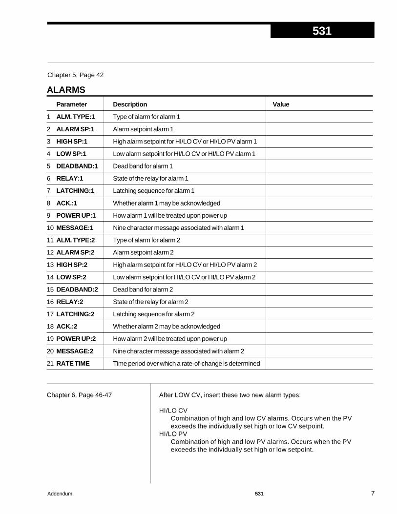
531
Addendum 531 7
Chapter 6, Page 46-47 After LOW CV, insert these two new alarm types:
HI/LO CVCombination of high and low CV alarms. Occurs when the PVexceeds the individually set high or low CV setpoint.
HI/LO PVCombination of high and low PV alarms. Occurs when the PVexceeds the individually set high or low setpoint.
Chapter 5, Page 42
ALARMS
Parameter Description Value
1 ALM. TYPE:1 Type of alarm for alarm 1
2 ALARM SP:1 Alarm setpoint alarm 1
3 HIGH SP:1 High alarm setpoint for HI/LO CV or HI/LO PV alarm 1
4 LOW SP:1 Low alarm setpoint for HI/LO CV or HI/LO PV alarm 1
5 DEADBAND:1 Dead band for alarm 1
6 RELAY:1 State of the relay for alarm 1
7 LATCHING:1 Latching sequence for alarm 1
8 ACK.:1 Whether alarm 1 may be acknowledged
9 POWER UP:1 How alarm 1 will be treated upon power up
10 MESSAGE:1 Nine character message associated with alarm 1
11 ALM. TYPE:2 Type of alarm for alarm 2
12 ALARM SP:2 Alarm setpoint alarm 2
13 HIGH SP:2 High alarm setpoint for HI/LO CV or HI/LO PV alarm 2
14 LOW SP:2 Low alarm setpoint for HI/LO CV or HI/LO PV alarm 2
15 DEADBAND:2 Dead band for alarm 2
16 RELAY:2 State of the relay for alarm 2
17 LATCHING:2 Latching sequence for alarm 2
18 ACK.:2 Whether alarm 2 may be acknowledged
19 POWER UP:2 How alarm 2 will be treated upon power up
20 MESSAGE:2 Nine character message associated with alarm 2
21 RATE TIME Time period over which a rate-of-change is determined

531
8 531 Addendum
Appendix A, Page A-1 The Menu Flowchart has been modified accordingly:
SEC. CODE HOST KEY MAN. KEY MAN. OUT LOCAL SP ALARM ACK.
OPERATION
CONFIG.
LOCAL OUT.
CUST. LINR.
ALARMS
SECURITY
SER. COMM.
PROP. BAND RESET RATE LOADLINE SP SOURCE MAN.RAMP
LOST HOST HOST. RESTR. CV RANGE CONTACT 1 CONTACT 2
CONTACT 5 WATCHDOG LINE FREQ. OUTPUT 1 PID ACTION
CONTACT 3
CONTACT 4
STN. NAME
AUTO.LO.LIM. AUTO.HI.LIM. MAN.OUT 1 MAN.OUT 2 PWR.UP:MODE MAN. PWR.UP
PV INPUT
OPERATION
BAUD RATE CRC
HOST RAMP
STATION
LOW SP:1 DEADBAND:1ALARM SP:1 HIGH SP:1 RELAY:1
ALARM SP:2LATCHING:1 ACK:1 ALM. TYPE:2MESSAGE:1POWER UP:1
HIGH SP:2 RELAY:2 LATCHING:2LOW SP:2 DEADBAND:2
POWER UP:2 MESSAGE:2 RATE TIME
RSP INPUT RSP TYPE RSP LOW RSP HIGH RSP.OFFSET RSP GAIN TRACKING
RSP. RESTOR.
PV TYPE DEG. F/C/K DECIMAL HI RANGELINEARIZE LOW RANGE HI RANGE
PV BREAK RESTOREFILTER PV OFFSET PV GAIN
1ST.INPT 1ST.PV 2ND.INPT 2ND P. 15TH.INPT 15TH.PV
CONFIGURE
Manual ModeHost Mode Automatic Mode
PRESS MANUAL
PRESSFAST
+MENU
PRESS MENUto traverse parameters for a given menu
PRESSFAST
+MENU
PRESSDISPLAY
orACK
PRESS MANUAL(TOGGLE)
PRESSMENU
OPERATING MODES
SET UP MODES
PRESSFAST+MENUto traverse menus
ALM. TYPE:1
ACK:2
PRESS HOST (TOGGLE)

531
Addendum 531 9
Appendix B, Page B-1 With the modifications to the case and addition of the mounting collar, theparts drawings have been modified. Also, note the new part numbers.
BEZELGASKET
CONTROLLER BODYshown with mountingcollar in place
MOUNTINGCOLLAR
CIRCUIT BOARD SUPPORT(BEZEL INSERT)
OPERATOR INTERFACEASSEMBLYshown with bezelinsert in place
CIRCUIT BOARDS
ITEM PART #Output Modules
Mechanical Relay Module 535 600Analog (Milliamp Module) 535 601Solid State Relay Module 535 602DC Logic (SSR Drive) Module 535 603Loop Power Module 535 604RS-485 Communications Module 535 705
Repair/Replacement PartsOperator Interface Assembly 531 632Power Supply Circuit Board 535 730Microcontroller Circuit Board 535 731Option Circuit Board w/no Options 535 720Option Circuit Board w/Set of 5 Digital Contacts 535 721EPROM 531 531 740Lithium Battery 093 044Jumper Kit: Set of All Jumper Connectors 535 660Gasket Kit: 1 Panel Gasket & 1 Bezel Gasket 535 662Mounting Kit: Mounting Collar & 4 screws 535 761Bezel Retention Screw Kit 535 663Module Retention Kit for Outputs 1-3 ( Includes Retention Plate) 535 664Module Retention Kit for Output 4: Set of 5 Tie Wraps 535 665Circuit Board Support (Bezel Insert) 535 075Engineering unit labels (1 sheet) 535 106531 Bypass board 532 100

531
10 531 Addendum
The following pages replace Appendix D of the 531 manual.
Appendix C, Page C-1 Changes and additions to the troubleshooting error messages:
When does it occur?
Whenever the memory is cleared andall parameters revert to factory defaultsettings. This may be done by pur-posely clearing the memory or whenthe unit is powered up for the first timeor if the software version is changed.
Indicates that the calibration data hasbeen lost. Occurs when there is a totalloss of memory.
On power up, a problem with theEPROM is detected. Controller locksup until fixed.
Upon power up, controller senses thatthe modules needed for control asdetermined by software configurationare not present.
The cold junction is sensed as lost.
During power up an EEPROM failure isdetected. Controller locks up untilfixed.
When the controller is powered up withdefault calibration data (input andoutput accuracy specifications may bemet).
During power up, a discrepancy wasfound between the EEPROM's andcontroller's model numbers. Controllerlocks up until fixed.
Message
DEFAULTS
LOST CAL. orERROR: BAD CAL. DATA
ERROR: ROM CHECKSUM
OUT1 CONF orOUT2 CONF orOUT3 CONF or
OUT4 CONF
LOST CJC
ERROR: BAD EEPROM
NEEDS CAL.
ERROR: BAD MODEL NUM.
What to do:
Changing any Set Up parameter willclear the message. If due to somethingother than the user purposely clearingthe memory, call factory for assistance.
Problem should never happen. Mustcorrect the situation and recalibrate. Callfactory for assistance.
Call factory for assistance.
Must power down and install correctmodule combination or mustreconfigure the controller to matchthe current module combination.
Call factory for assistance.
This is a fatal error and requires andEEPROM change. Call factory forassistance.
Enter calibration menu andrecalibrate the controller. Call factoryfor assistance.
This is a fatal error and requires anEPROM or EEPROM change. Callfactory for assistance.

531
Addendum 531 11
APPENDIX DCALIBRATION• To maintain optimum performance, once a year calibrate the analog
input, the cold junction and milliamp output (when used). To achievepublished accuracy specifications, follow directions carefully and usecalibrated instruments of like quality to those suggested.
• If the controller is moved into an alternate case, or the hardware configura-tion is changed, and the thermocouple input is needed, recalibrate the coldjunction for maximum accuracy. Failure to do so may result in smalljunction temperature (0.6°C/1.1°F).
ANALOG IN
CALIBRATE
ANLG. OUT
CALIBRATE
CAL. 120mV, etc.
OUTPUT X, etc
5.0000
CAL VREF
4 mA
OUTPUT "X"
DISPLAY ONLY
TO RESET
PUSH MENU
COMPLETED
RESET
RESET
SKIPPED
SCAN
HARDWARE
PRESS ACK
PRESS ACK
PRESS ACK
PRESS ACK
PRESS ACK
After twoseconds
PRESSMENU
before twoseconds
MENU DATA
RESET
PRESS ACK
PRESS MENU
PRESS MENU
mA CALIB.
COMPLETED
mA CALIB.
FAILED
PRESS ACK
PRESS ACK
PRESS MENU
PRESS MENUPRESS MENU
COLD JUNC.
CALIBRATE
PRESS ACK
PV= –150 CPRESS ACK
PRESS MENUPRESS MENU
PRESS MENUPRESS MENU
PRESS MENU
PRESS MENU
ANA. mA IN
CALIBRATE
JUMPER=mA
SET BOTH
PRESS ACK
PV=20mAPRESS ACK
Power DownMove Jumpers
Power Up PRESS ACK
SP=20mAAttach 20mA
to PVPress ACK
Attach 20mAto SP
Press ACKIf mA calibration values are
OK.
If mA calibration values are out of range.
Access the parts of the calibration menu as shown in Figure D.1.ATTENTION!The 531 comes from the factory with one milliamp output module installed in po-sition (output) 2 and relays in position (outputs) 3 and 4. These must not bemodified. You may install a mechanical relay, solid state relay or DC logic mod-ule in position (output) 1 for alarm functions.

531
12 531 Addendum
PREPARATION FOR ALL INPUT CALIBRATIONS
Equipment for analog input calibration:• Precision 5-1/2 or 6-1/2 digit multimeter, e.g., Fluke 8842® or HP3478A®
(a 4-1/2 digit meter will sacrifice accuracy)• Four small pieces of wire• Test leads with clips• #2 Phillips screwdriver
Additional equipment for thermocouple input:• Precision thermocouple calibrator, e.g., Micromite II® by Thermo Electric
Instruments• Special limits grade, Type T thermocouple wire
1. Disconnect power to the instrument.
2. Remove chassis from case.
3. On the Microcontroller Circuit Board, locate jumper locations marked PV1 and2nd near the edge connector. Reposition both jumper connectors in the 2ndlocation onto pins for V and TC as shown in Figure D.2.
4. Connect hook up wires between terminals 31 and 32 as shown in Figure D.3,and the multimeter.
Set the meter for DC volts.
5. Reinsert chassis into the case and apply power.
The 2nd and 3rd display should read CALIBRATE ANALOG IN.
6. Allow the controller to warm up for at least 30 minutes.
7. Press the ACK key to get to the first step/parameter.
The 2nd display should show CAL. VREF; the 3rd display should show a valueclose to 5.0000.
8. The multimeter should read a value in the range 4.9750 - 5.0250.
Use the and (and FAST) keys on the controller until the display on thecontroller matches the meter reading.
9. Press MENU key.
The 2nd display should show CAL. 120mV. The 3rd display should show avalue close to 120.000. Match controller display to multimeter value using and keys.
VMA
TCsRTD
TCt
EP
RO
M
BATTERY
ASS'Y TB1
PV
1
VMA
2ND
PV INPUTJUMPER
CONFIGURATION
TCsRTD
TCt
TB2CALIBRATIONJUMPERS—SELECT VAND TCs
Jumper locations forAnalog,Thermocouple and Milliamp calibration
P2
P1
Figure D.2Microcontroller Circuit Board
WARNING! Electric Shock Hazard!Terminals 1 and 2 carry live power.Do not touch these terminals whenAC power is on.
3231
PV+
PV–
Figure D.3Input Calibration

531
Addendum 531 13
10. Press MENU four more times. Each time, match the displays of the controllerand the multimeter. Press ACK when done.
The 2nd display should show CALIBRATE; the 3rd display should show ANA.mA IN.
11. Turn off power to the unit.
12. For thermocouple input, proceed to the Thermocouple Cold Junction Cali-bration.
13. For milliamp input , proceed to Analog Milliamp Input Calibration.
14.For milliamp output calibration, let the controller warm up for 10 minutes, thenskip to step 5 of Milliamp Output Calibration.
15. If calibration is complete, place all the jumpers back in their original positions(as specified in Chapter 3).
THERMOCOUPLE COLD JUNCTION CALIBRATION1. Connect the two pairs of T/C wire to terminals 31 and 32 as shown in Figure D.4.
Make sure the T/C wires are floating (disconnect from the multimeter also), andare not touching each other.
2. Turn on power to the unit and let controller warm up for 30 minutes in the normalhorizontal position: while the unit is warming up, the rear face of the controllershould be vertical, not horizontal.
3. Press the MENU key until the display indicates CALIBRATE COLD JUNC.
4. Press the ACK key. The display should show PV = -150 C PRESS ACK.
5. Connect both pairs of T/C wires in parallel—do not daisy chain—to a Type Tthermocouple calibrator. (Both pairs must be connected or the calibration willnot be accurate.)
6. Set the thermocouple calibrator to an output value of -150° C for a Type T ther-mocouple and allow the calibrator to stabilize for a few minutes.
7. Press ACK to initiate calibration of the cold junction.
8. For milliamp output calibration, proceed to Milliamp Output Calibration. Letthe controller warm up for 10 minutes, then skip to step 5.
9. If calibration is complete, power down, then place all the jumpers in their origi-nal positions (as specified in Chapter 3).
ANALOG MILLIAMP INPUT CALIBRATION1. Remove the thermocouple wires (if present) from terminals 31 and 32. Replace
them with pieces of wire that will be connected to a 20 milliamp input current(see Figure D.5). Make sure terminal screws are securely tightened, but do notconnect the wires yet (leave inputs floating).
2. Turn on power to the unit.
3. Press MENU until the display indicates CALIBRATE ANA. mA IN, thenpress ACK.
If the display shows PV=20mA PRESS ACK, move ahead to step #8.
4. The controller will display SET BOTH JUMPER=mA.
5. Power down the controller and remove chassis from the case.
23
24
21
22
19
20
17
18
29
30
27
28
25
26
32
31
Type Tthermocouplewire (floating)
– red
+ blue
Figure D.4Thermocouple Cold JunctionCalibration Wiring
Figure D.5Analog mA Input Calibration
23
24
21
22
19
20
17
18
29
30
27
28
25
26
32
31PV–
PV+
SP–
Wires to 20mAcurrent (floating)
SP+

531
14 531 Addendum
6. Remove both input jumper connectors from the pins in the 2nd position. Placeone of the jumpers on the PV1 position mA pins, and place the other jumper onthe 2nd position mA pins, as shown in Figure D.6.
7. Reinsert the chassis into the case and apply power. The controller should dis-play PV=20mA PRESS ACK to indicate it is ready to calibrate the PV milliampinput.
8. Connect a precision 20mA input to the PV terminals (31 is PV-, 32 is PV+). Makesure the terminal connections are fastened tightly and that a 20mA current isflowing through PV. Do not connect the 20mA current to SP yet.
9. Let the controller warm up for at least 10 minutes (keep in normal horizontalposition). Make sure the current is flowing, then press ACK to calibrate the PVinput.
10. If the controller briefly displays SP=20mA PRESS ACK, PV calibration was suc-cessful. Move on to step 12.
11. If the controller briefly displays mA CALIB. FAILED, PV calibration was not suc-cessful.
Check the 20mA connections, and return to step #3 to recalibrate the PV input.
12. Remove the 20mA input from the PV terminals, and attach it to the SP terminals(see Figure D.5).
Make sure the terminal connections are fastened tightly and that a 20mA cur-rent is flowing through SP terminals.
13. Let the controller warm up for an additional 5 minutes (keep in the normal hori-zontal position). Make sure the current is flowing, then press ACK to calibratethe SP input.
14. If the controller briefly displays mA CALIB. COMPLETED, SP calibration wassuccessful and the analog milliamp calibration procedure has been completed.If calibration is complete, power down. Place the jumpers into their originalpositions (see Chapter 4).
15. If the controller briefly displays mA CALIB. FAILED, SP calibration was not suc-cessful. Check the 20mA connections, and return to step #3 to recalibrate thePV and SP inputs.
MILLIAMP OUTPUT CALIBRATIONOnce a year, calibrate the milliamp output to maintain optimal performance.Additionally, calibrate an output whenever a new milliamp module is in-stalled.The 531 local output should be calibrated at terminals 5 and 6 (OUT2– andOUT2+). The bypass circuitry need not be removed to perform this calibration.
Equipment needed:• Precision 5-1/2 digit multimeter, e.g., Fluke 8842® or HP3478A® ( 4-1/2 digit
meters sacrifice accuracy)• Two small pieces of wire for every milliamp output• Test leads with clips ends• #2 Phillips screwdriver
1. Disconnect power to the instrument.
2. Remove chassis from case.
Figure D.6Analog mA Input Jumper Position
VMA
TCsRTD
TCt
TB1
PV
1
VMA
2ND
PUTPER
RATION
TCsRTD
TCt
TB2RATIONERS—
ECT V TCs
P2
P1
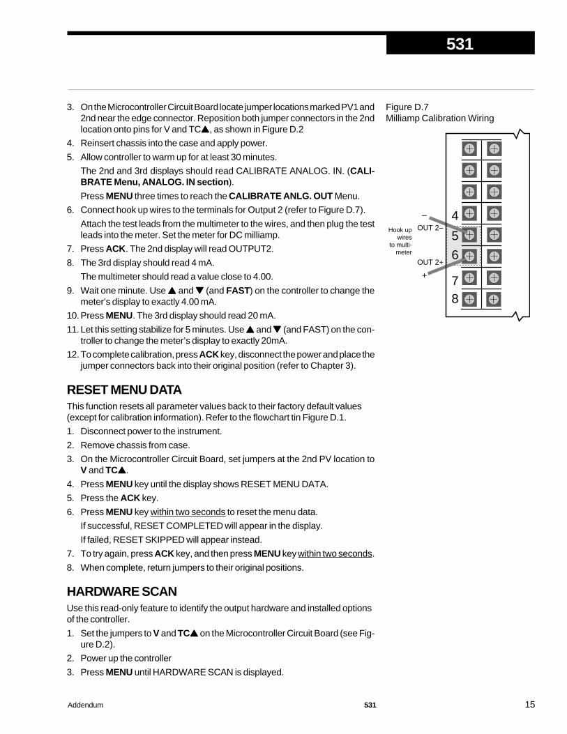
531
Addendum 531 15
3. On the Microcontroller Circuit Board locate jumper locations marked PV1 and2nd near the edge connector. Reposition both jumper connectors in the 2ndlocation onto pins for V and TC, as shown in Figure D.2
4. Reinsert chassis into the case and apply power.
5. Allow controller to warm up for at least 30 minutes.
The 2nd and 3rd displays should read CALIBRATE ANALOG. IN. (CALI-BRATE Menu, ANALOG. IN section).
Press MENU three times to reach the CALIBRATE ANLG. OUT Menu.
6. Connect hook up wires to the terminals for Output 2 (refer to Figure D.7).
Attach the test leads from the multimeter to the wires, and then plug the testleads into the meter. Set the meter for DC milliamp.
7. Press ACK. The 2nd display will read OUTPUT2.
8. The 3rd display should read 4 mA.
The multimeter should read a value close to 4.00.
9. Wait one minute. Use and (and FAST) on the controller to change themeter’s display to exactly 4.00 mA.
10. Press MENU. The 3rd display should read 20 mA.
11. Let this setting stabilize for 5 minutes. Use and (and FAST) on the con-troller to change the meter’s display to exactly 20mA.
12.To complete calibration, press ACK key, disconnect the power and place thejumper connectors back into their original position (refer to Chapter 3).
RESET MENU DATAThis function resets all parameter values back to their factory default values(except for calibration information). Refer to the flowchart tin Figure D.1.
1. Disconnect power to the instrument.
2. Remove chassis from case.
3. On the Microcontroller Circuit Board, set jumpers at the 2nd PV location toV and TC.
4. Press MENU key until the display shows RESET MENU DATA.
5. Press the ACK key.
6. Press MENU key within two seconds to reset the menu data.
If successful, RESET COMPLETED will appear in the display.
If failed, RESET SKIPPED will appear instead.
7. To try again, press ACK key, and then press MENU key within two seconds.
8. When complete, return jumpers to their original positions.
HARDWARE SCANUse this read-only feature to identify the output hardware and installed optionsof the controller.
1. Set the jumpers to V and TC on the Microcontroller Circuit Board (see Fig-ure D.2).
2. Power up the controller
3. Press MENU until HARDWARE SCAN is displayed.
Figure D.7Milliamp Calibration Wiring
87
6
5
4
OUT 2+
OUT 2–
+
–
Hook upwires
to multi-meter

531
16 531 Addendum
4. Press ACK to initiate the hardware display.
5. When complete, return jumpers to their original positions (as in Chapter 3).
QUICK CALIBRATION PROCEDURE For mA or V inputsThis procedure is for the benefit of users that have ISO or other standards thatrequire periodic calibration verification. It enables verification and modificationof the process variable input without entering the “Factory Configuration”mode.
1. Power down the 531 controller and place the input jumpers in the desiredposition (refer to Figure D.2 and Figure D.6).
2. Replace the process variable (PV) input signal with a suitable calibrationdevice.
3. Apply power and allow controller to warm up for 30 minutes.
4. Place controller in manual mode. Go to the PV INPUT menu, PV OFFSETparameter.
5. Adjust the calibration device to an output signal equal to the 0% rangevalue for the particular input sensor (for example, 4mA for a 4-20 mA input).
6. Verify value indicated in the 1st display is equal to the 0% range value forthe particular input sensor. If incorrect, use the and keys to scroll tothe correct value.
7. For a linear voltage or mA input: Press MENU to scroll to the PV GAINparameter.
For other inputs: go to step #8.
8. Adjust the calibration device to an output signal equal to the 100% rangevalue for the particular sensor.
9. Verify that the value shown in the 1st display is equal to 100% of the rangevalue for the particular input sensor. If the value is not correct, use the and keys to scroll to the correct value.
10. Repeat steps 4 through 8 to verify all values.
11. Press DISPLAY to return to the Operation mode.

531
Addendum 531 17
PowerSupply
Line
LNG
E
E
Isolated Output Ground
Earth Referenced Ground
Internal Ground
E
+V
+Vd
+Ve
DigitalInputs 1-5
SlidewireInput
CVInput
RSPInput
PVInput
Multiplexer
ISO
CPUOutput 1
ISO GroundReferenced
Output 2ISO GroundReferenced
Output 3ISO GroundReferenced
Output 4ISO GroundReferenced
RS485 SerialCommunications
Interface
Appendix F, Page F-1 This section has been added: Appendix F, Isolation Block Diagram
1. Each of the three ground circuits are isolated from each other towithstand a potential of 500 volts for 1 minutes, or 600 volts for1 second.
2. CV, RSP, Slidewire and the PV & SP inputs are isolated to with-stand 50 volts peak between each other for 1 minute.
3. Milliamp, Loop Power and SSR Drive modules in output posi-tion 1, 2, 3 and 4 are not isolated from each other.
4. Inputs are not isolated from the analog output due to the failsafepass-through circuit.
Milliamp Module Mechanical Relay
+V
SSR Driver
+V
Loop Power SSR Output

Installation
Installation Guide 500 Series 1
500 SERIESProcess Controllers
Hardware Installationand Modification
Manualfor Electronic Products
Series 531, 532,535, 545, 555
Model 2
5 0 0
Form M500 V7
M500 V 7, APRIL 2016

2 500 Series Installation Guide
Installation
INTRODUCTION
This technical brochure provides hardware installation and modification instructions for our controllers:Series 531, 532, 535, 545, and 555. Use these instructions with the following kits:
EPROM Kits531-740 ................ 531 EPROM Kit532-740 ............... 532 EPROM Kit535-741 ................ 535 EPROM Kit (RSP)535-775 ............... 535 Profiler EPROM Kit (No RSP)535-776 ............... 535 Profiler EPROM Kit (RSP)535-740 ................ 535 EPROM Kit (No RSP)545-740 ................ 545 EPROM Kit (No RSP)545-741 ................ 545 EPROM Kit (RSP)555-740 ................ 555 EPROM Kit
Microcontroller (MCU) Board Kits535-731 ............... MCU Board Kit545-733 ............... MCU Board Kit with CE Option
Option Board Kits535-720 ............... 531, 532, 535, 545 Option Board Kit
(No Options)535-721 ............... 531, 532, 535, 545 Option Board Kit
(Digital Inputs)535-722 ............... 535, 545 Option Board Kit
(Slidewire Feedback)535-723 ............... 535, 545 Option Board Kit
(Digital Inputs and Slidewire Feedback)545-724 ............... 531, 532, 535, 545, 555 Option Board Kit
(RSP)545-725 ............... 531, 532, 535, 545, 555 Option Board Kit
(Digital Inputs and RSP)545-726 ............... 535, 545, 555 Option Board Kit
(Slidewire Feedback and RSP)545-727 ............... 535, 545, 555 Option Board Kit
(Digital Inputs, Slidewire Feedback,and RSP)
Display Assembly Kits531-632 ............... 531 Display Assembly Kit532-632 ............... 532 Display Assembly Kit535-632 ............... 535 Display Assembly Kit545-634 ............... 545 Display Assembly Kit555-632 ............... 555 Display Assembly Kit
Output and Communications Module Kits532-600 ............... 531, 532 Analog Module Kit535-600* .............. Mechanical Relay Module Kit535-601* .............. Milliamp Module Kit535-602* .............. SSR Module Kit535-603* .............. SSR Drive Module Kit535-604* .............. Loop Power Module Kit535-705* .............. RS-485 Communications Module Kit
Power Supply Kit535-730* .............. 90 to 250VAC Power Supply Kit535-732 ............... 24VAC/VDC Power Supply Kit
Mounting Kit535-761* .............. Mounting Kit
Miscellaneous Kits532-100 ............... 531, 532 Bypass Board Kit535-188* .............. Rear Terminal Upgrade Kit535-660 ............... 531, 532, 535, 545, 555 Jumper Kit535-662* .............. Gasket Kit
(1 Panel Gasket, 1 Bezel Gasket)535-763* .............. Bezel Retention Screw Kit535-664* .............. Module Retention Kit
(Retention Plate and Tie Wrap)535-665* .............. Module Retention Tie Wrap Kit093-128* .............. Lithium Battery
HOW TO USE THIS MANUAL:A. CAUTION: Static discharge will cause damage to equipment. Always ground yourself with a wrist grounding
strap when handling electronics to prevent static discharge.
B. Before removing or inserting any hardware on the controller, copy down all configuration parameters. Also,replacing the battery, EPROM or MCU Board will erase parameter settings and they will need to be reset.
C. For all hardware adjustments, perform steps 1, 2 and 3.
D. Follow the guide and complete any additional steps as required by your particular application.
E. Complete your hardware adjustments with steps 15, 16, 17, 18, 19 & 20.
EQUIPMENTTo make any hardware changes to the units, you will need the following equipment:
• Wrist grounding strap • Phillips screwdriver (#2)
• Small flat blade screwdriver • Wire cutters
• I.C. Extractor (if changing the EPROM)
* Universal Kit (can be used with all 500 Series Controllers)

Installation
Installation Guide 500 Series 3
one of the larger two boards from the OptionBoard (Photo 4). Be careful not to bend theconnector pins. Separate the other board in thesame manner.
Figure 2 (opposite page) shows the MicrocontrollerBoard, Option Board and Power Supply Board.
To Add or Change Output ModulesThe 500 Series units have provisions for four outputmodules. The units come factory configured withspecified modules installed in appropriate locations.You can make field modifications by properly remov-ing and/or adding the modules into the appropriatesockets.
Three of the output sockets are located on the PowerSupply Circuit Board. A fourth output socket islocated on the Option Board (refer to Figure 2).
5. A retention plateand tie wrap holdOutput modules 1, 2,and 3 (on the PowerSupply board) firmlyin place. To removethe retention plate,snip the tie wrapwith wire cutters(Photo 5).
6. A disposable tie wrapholds Output module4 (on the Optionboard) in place. Toremove the module,snip the tie wrap(Photo 6).
7. Inspect each modulebefore installation tomake sure the pinsare straight. Alignthe pins with thesocket holes andcarefully insert themodule. Press down on the module to seat itfirmly on the board.
INSTRUCTIONS
To Disassemble the UnitFor any hardware modifications, disassemble the unit.
1. With power off, loosen four captive front screws witha Phillips screwdriver. Remove the four screws.
2. Slide the chassis out of the case by pulling on frontface plate assembly at the bezel (see Figure 1).
3. Locate the retentionclips holding the frontface assembly to therest of the chassis.Pry apart theseretention clips gentlywith a screwdriver toseparate the printedcircuit board groupfrom the front faceassembly (Photo 3).Take care not tobreak the clips orscratch the circuit board.
The Microcontroller Board and Power Supply Boardremain attached to the Operator Interface Assem-bly by wired connectors.
4. The Microcontrollerand Power Supplyboard are attachedto either side of theOption board bymale/female pinconnectors. Use agentle rocking motionand carefully applypressure in a uniformdirection to separate
Figure 1Location of Printed Circuit Boards for HardwareConfiguration
Photo 3. Pry Clips
Photo 4. Separate Boards
Photo 5.Remove Retention Plate
Photo 6.Snip Tie Wrap on Mod. 4
CAUTION: Always snip the tie wrap on top of theRetention Plate, as shown in photo 5, to preventdamage to the surface mount components.

4 500 Series Installation Guide
Installation
Figure 2Microntroller Board,Option Board, andPower Supply Board
NOTE:If you replace the EPROM chip, youmust align the notch facing the frontof the unit.
NOTE:The 5- and 22-Pin connnectors onthe boards are all keyed so theywill only align one correct way.
Front of Unit Back of Unit(toward Operator Interface) (toward rear terminals)
Male 22-PinConnector
Male 22-PinConnector
Male 12-PinConnector
Male 22-PinConnector
Output 4
5-Pin Connector
Female 22-Pin Connector Female 22-Pin Connector
5-Pin Connector
ModuleRetention
Plateover Outputs 1,2,3
12-Pin FemaleConnector
22-Pin FemaleConnector
JumpersNO and NC
VMA
VMATCTCRTD
NO
J1
NC
NO
J2
NC
NO
J3
NC
TB1
PV
12N
D
TB2
TCTCRTD
Remote Setpoint Jumper
EPROM
BATTERY

Installation
Installation Guide 500 Series 5
Note: When adding Option board for 5digital inputs, associated screw terminal inthe rear terminal block must be installed.(See information on page 1 for ordering aScrew Kit.)
To Change the Power Supply orMicrocontroller (CPU) Board10. For the Microcontroller Board, disconnect the 5-pin
female connector that wires it to the DisplayAssembly. Reattach the connector to the newboard. You can only orient the connector one way.
For the Power Supply Board, disconnect the 5-pinfemale connector that wires it to the DisplayAssembly. Reattach the connector to the newboard. You can only orient the connector one way.
To Change the Display Assembly11. Disconnect the 5-pin female connector that wires
the Microcontroller Board to the Display Assembly.Disconnect the 5-pin female connector that wiresthe Power Supply Board to the Display Assembly.
12. Attach the new Display Assembly to the boards atthe appropriate connectors.
To Change the EPROM13. The EPROM is located on the Microcontroller
Circuit board (Figure 2). It has a white label thatlist the part number and software revision level.Use an I.C. Extractor to carefully remove theEPROM. If you do not have an I.C. extractor,gently use a small flat blade screwdriver to pry upthe EPROM. DO Not bend the EPROM legs.
14. Carefully insert the new EPROM. To positioncorrectly, match the notched end of the EPROM tothe markings on the board. The notched end willface towards the display. Make sure all pins are inthe socket.
To Reassemble the Unit15. (See Figure 2) Align the connector pins on the
Option Board with the connector sockets on theMicrocontroller and Power Supply boards.Squeeze them together, making certain all threeare properly seated against one another. Checkalong the side edges for gaps. Make sure theconector is properly aligned. Also, check that thecable assemblies are not pinched.
16. (See Figure 2) Align the board assembly with thefront face assembly, with the Option board at thebottom (see Figure 1). Reinstall the retentionclips. Align the boards into the slots of the frontface assembly and the clips will snap into place.
17. When you are ready to reassemble the unit, alignthe boards in the chassis with the case's top andbottom grooves. Press firmly to slide the chassisinto the case. If you have difficulty, check that youhave properly oriented the chassis, and there areno screws interfering with the case.
18. Carefully insert and align screws. Tighten themuntil the bezel is seated firmly against the gasket.DO NOT OVERTIGHTEN.
19. If may be necessary to re-configure the softwarefeatures of your controller or station. Please referto your User’s Manual.
20. To maintain NEMA 4X Rating, you may need newmounting gaskets, order part #535-662. Refer toyour user’s manual.
8. Replace tie wraps for the Retention Plate and forOutput Module 4 with new ones.
Failure to use these devices may result in aloosening of the module and eventualfailure. If you ordered a module separately,it should have come with a tie wrap. Anextra set of tie wraps is available by order-ing Part #535-665.
Note: For greatest accuracy, milliampmodules added for retransmission must becalibrated per instructions in Operator'sManual.
To Change the Option Board9. (See Photos 3 and 4) Replace the existing Option
board with the NEW one.
CAUTIONDo not scratch the boards or bend the pins of theconnectors.
CAUTION
Static discharge will cause damage to equip-ment. Always ground yourself with a wristgrounding strap when handling electronicsto prevent static discharge.

To return equipment to Moore Industries for repair, follow these four steps:
1. Call Moore Industries and request a Returned Material Authorization (RMA) number.
Warranty Repair –If you are unsure if your unit is still under warranty, we can use the unit’s serial numberto verify the warranty status for you over the phone. Be sure to include the RMAnumber on all documentation.
Non-Warranty Repair –If your unit is out of warranty, be prepared to give us a Purchase Order number whenyou call. In most cases, we will be able to quote you the repair costs at that time.The repair price you are quoted will be a “Not To Exceed” price, which means that theactual repair costs may be less than the quote. Be sure to include the RMA number onall documentation.
2. Provide us with the following documentation:
a) A note listing the symptoms that indicate the unit needs repairb) Complete shipping information for return of the equipment after repair
c) The name and phone number of the person to contact if questions arise at the factory
3. Use sufficient packing material and carefully pack the equipment in a sturdy shippingcontainer.
4. Ship the equipment to the Moore Industries location nearest you.
The returned equipment will be inspected and tested at the factory. A Moore Industriesrepresentative will contact the person designated on your documentation if more information isneeded. The repaired equipment, or its replacement, will be returned to you in accordance withthe shipping instructions furnished in your documentation.
WARRANTY DISCLAIMERTHE COMPANY MAKES NO EXPRESS, IMPLIED OR STATUTORY WARRAN-TIES (INCLUDING ANY WARRANTY OF MERCHANTABILITY OR OF FITNESSFOR A PARTICULAR PURPOSE) WITH RESPECT TO ANY GOODS OR SER-VICES SOLD BY THE COMPANY. THE COMPANY DISCLAIMS ALL WARRAN-TIES ARISING FROM ANY COURSE OF DEALING OR TRADE USAGE, ANDANY BUYER OF GOODS OR SERVICES FROM THE COMPANY ACKNOWL-EDGES THAT THERE ARE NO WARRANTIES IMPLIED BY CUSTOM ORUSAGE IN THE TRADE OF THE BUYER AND OF THE COMPANY, AND THATANY PRIOR DEALINGS OF THE BUYER WITH THE COMPANY DO NOT IM-PLY THAT THE COMPANY WARRANTS THE GOODS OR SERVICES IN ANYWAY.
ANY BUYER OF GOODS OR SERVICES FROM THE COMPANY AGREESWITH THE COMPANY THAT THE SOLE AND EXCLUSIVE REMEDIES FORBREACH OF ANY WARRANTY CONCERNING THE GOODS OR SERVICESSHALL BE FOR THE COMPANY, AT ITS OPTION, TO REPAIR OR REPLACETHE GOODS OR SERVICES OR REFUND THE PURCHASE PRICE. THECOMPANY SHALL IN NO EVENT BE LIABLE FOR ANY CONSEQUENTIAL ORINCIDENTAL DAMAGES EVEN IF THE COMPANY FAILS IN ANY ATTEMPTTO REMEDY DEFECTS IN THE GOODS OR SERVICES , BUT IN SUCH CASETHE BUYER SHALL BE ENTITLED TO NO MORE THAN A REFUND OF ALLMONIES PAID TO THE COMPANY BY THE BUYER FOR PURCHASE OF THEGOODS OR SERVICES.
RETURN PROCEDURES
ANY CAUSE OF ACTION FOR BREACH OF ANY WARRANTY BY THECOMPANY SHALL BE BARRED UNLESS THE COMPANY RECEIVESFROM THE BUYER A WRITTEN NOTICE OF THE ALLEGED DEFECT ORBREACH WITHIN TEN DAYS FROM THE EARLIEST DATE ON WHICH THEBUYER COULD REASONABLY HAVE DISCOVERED THE ALLEGED DE-FECT OR BREACH, AND NO ACTION FOR THE BREACH OF ANY WAR-RANTY SHALL BE COMMENCED BY THE BUYER ANY LATER THANTWELVE MONTHS FROM THE EARLIEST DATE ON WHICH THE BUYERCOULD REASONABLY HAVE DISCOVERED THE ALLEGED DEFECT ORBREACH.
RETURN POLICYFor a period of thirty-six (36) months from the date of shipment, and undernormal conditions of use and service, Moore Industries ("The Company") willat its option replace, repair or refund the purchase price for any of its manu-factured products found, upon return to the Company (transportation chargesprepaid and otherwise in accordance with the return procedures establishedby The Company), to be defective in material or workmanship. This policyextends to the original Buyer only and not to Buyer's customers or the usersof Buyer's products, unless Buyer is an engineering contractor in which casethe policy shall extend to Buyer's immediate customer only. This policy shallnot apply if the product has been subject to alteration, misuse, accident, ne-glect or improper application, installation, or operation. THE COMPANYSHALL IN NO EVENT BE LIABLE FOR ANY INCIDENTAL OR CONSE-QUENTIAL DAMAGES.
United States • [email protected]: (818) 894-7111 • FAX: (818) 891-2816
Australia • [email protected]: (02) 8536-7200 • FAX: (02) 9525-7296
Belgium • [email protected]: 03/448.10.18 • FAX: 03/440.17.97
The Netherlands • [email protected]: (0)344-617971 • FAX: (0)344-615920
China • [email protected]: 86-21-62491499 • FAX: 86-21-62490635
United Kingdom • [email protected]: 01293 514488 • FAX: 01293 536852
Specifications and Information subject to change without notice.© 2006 Moore Industries-International, Inc.

User’s Manual Supplement500 Series
Process Controllers531, 532, 535, 545, 555
April 2016
PurposeThis supplement is to address the updated Micro Controller Board with removable Lithium Battery. Older models required to be serviced by Moore Industries to replace Lithium Battery which was soldered directly on the board, this is an inconvenience and has been resolved with a Micro Controller Board that has a replaceable Lithium Battery slot.
To replace battery in your 500 Series unit follow previous instructions found in M500 V6. Use a fl at head screwdriver to release battery and replace.
The Interface Solution Experts www.miinet.com
BATTERY
EPROM
5-Pin Connector
INSERT FLAT HEAD SCREWDRIVERTIP HERE TO RELEASE BATTERY
Female 22-Pin ConnectorFemale 22-Pin Connector
Figure 1. Removable Lithium Battery
You can order replacement directly fro Moore Industries using this part number 800-867-52 or an equivalent CR2450 3V Coin Cell Lithium Battery.

To return equipment to Moore Industries for repair, follow these four steps:
1. Call Moore Industries and request a Returned Material Authorization (RMA) number.
Warranty Repair –If you are unsure if your unit is still under warranty, we can use the unit’s serial numberto verify the warranty status for you over the phone. Be sure to include the RMAnumber on all documentation.
Non-Warranty Repair –If your unit is out of warranty, be prepared to give us a Purchase Order number whenyou call. In most cases, we will be able to quote you the repair costs at that time.The repair price you are quoted will be a “Not To Exceed” price, which means that theactual repair costs may be less than the quote. Be sure to include the RMA number onall documentation.
2. Provide us with the following documentation:
a) A note listing the symptoms that indicate the unit needs repairb) Complete shipping information for return of the equipment after repair
c) The name and phone number of the person to contact if questions arise at the factory
3. Use sufficient packing material and carefully pack the equipment in a sturdy shippingcontainer.
4. Ship the equipment to the Moore Industries location nearest you.
The returned equipment will be inspected and tested at the factory. A Moore Industriesrepresentative will contact the person designated on your documentation if more information isneeded. The repaired equipment, or its replacement, will be returned to you in accordance withthe shipping instructions furnished in your documentation.
WARRANTY DISCLAIMERTHE COMPANY MAKES NO EXPRESS, IMPLIED OR STATUTORY WARRAN-TIES (INCLUDING ANY WARRANTY OF MERCHANTABILITY OR OF FITNESSFOR A PARTICULAR PURPOSE) WITH RESPECT TO ANY GOODS OR SER-VICES SOLD BY THE COMPANY. THE COMPANY DISCLAIMS ALL WARRAN-TIES ARISING FROM ANY COURSE OF DEALING OR TRADE USAGE, ANDANY BUYER OF GOODS OR SERVICES FROM THE COMPANY ACKNOWL-EDGES THAT THERE ARE NO WARRANTIES IMPLIED BY CUSTOM ORUSAGE IN THE TRADE OF THE BUYER AND OF THE COMPANY, AND THATANY PRIOR DEALINGS OF THE BUYER WITH THE COMPANY DO NOT IM-PLY THAT THE COMPANY WARRANTS THE GOODS OR SERVICES IN ANYWAY.
ANY BUYER OF GOODS OR SERVICES FROM THE COMPANY AGREESWITH THE COMPANY THAT THE SOLE AND EXCLUSIVE REMEDIES FORBREACH OF ANY WARRANTY CONCERNING THE GOODS OR SERVICESSHALL BE FOR THE COMPANY, AT ITS OPTION, TO REPAIR OR REPLACETHE GOODS OR SERVICES OR REFUND THE PURCHASE PRICE. THECOMPANY SHALL IN NO EVENT BE LIABLE FOR ANY CONSEQUENTIAL ORINCIDENTAL DAMAGES EVEN IF THE COMPANY FAILS IN ANY ATTEMPTTO REMEDY DEFECTS IN THE GOODS OR SERVICES , BUT IN SUCH CASETHE BUYER SHALL BE ENTITLED TO NO MORE THAN A REFUND OF ALLMONIES PAID TO THE COMPANY BY THE BUYER FOR PURCHASE OF THEGOODS OR SERVICES.
RETURN PROCEDURES
ANY CAUSE OF ACTION FOR BREACH OF ANY WARRANTY BY THECOMPANY SHALL BE BARRED UNLESS THE COMPANY RECEIVESFROM THE BUYER A WRITTEN NOTICE OF THE ALLEGED DEFECT ORBREACH WITHIN TEN DAYS FROM THE EARLIEST DATE ON WHICH THEBUYER COULD REASONABLY HAVE DISCOVERED THE ALLEGED DE-FECT OR BREACH, AND NO ACTION FOR THE BREACH OF ANY WAR-RANTY SHALL BE COMMENCED BY THE BUYER ANY LATER THANTWELVE MONTHS FROM THE EARLIEST DATE ON WHICH THE BUYERCOULD REASONABLY HAVE DISCOVERED THE ALLEGED DEFECT ORBREACH.
RETURN POLICYFor a period of thirty-six (36) months from the date of shipment, and undernormal conditions of use and service, Moore Industries ("The Company") willat its option replace, repair or refund the purchase price for any of its manu-factured products found, upon return to the Company (transportation chargesprepaid and otherwise in accordance with the return procedures establishedby The Company), to be defective in material or workmanship. This policyextends to the original Buyer only and not to Buyer's customers or the usersof Buyer's products, unless Buyer is an engineering contractor in which casethe policy shall extend to Buyer's immediate customer only. This policy shallnot apply if the product has been subject to alteration, misuse, accident, ne-glect or improper application, installation, or operation. THE COMPANYSHALL IN NO EVENT BE LIABLE FOR ANY INCIDENTAL OR CONSE-QUENTIAL DAMAGES.
United States • [email protected]: (818) 894-7111 • FAX: (818) 891-2816
Australia • [email protected]: (02) 8536-7200 • FAX: (02) 9525-7296
Belgium • [email protected]: 03/448.10.18 • FAX: 03/440.17.97
The Netherlands • [email protected]: (0)344-617971 • FAX: (0)344-615920
China • [email protected]: 86-21-62491499 • FAX: 86-21-62490635
United Kingdom • [email protected]: 01293 514488 • FAX: 01293 536852
Specifications and Information subject to change without notice.© 2006 Moore Industries-International, Inc.