plc mitsubishi.pdf
TRANSCRIPT

MELSECNET/H course(Q-series)
Mitsubishi Programmable Logic Controller Training ManualMELSECNET/H course(Q-series)
ME
LSE
CN
ET
/H course(Q
-series)
Mitsubishi Programmable Logic Controller
Training Manual
MODEL
MODELCODE
SCHOOL-Q-NET10H-E
13JW52
SH(NA)-080619ENG-A(0601)MEE
Specifications subject to change without notice.
When exported from Japan, this manual does not require application to theMinistry of Economy, Trade and Industry for service transaction permission.
HEAD OFFICE : TOKYO BUILDING, 2-7-3 MARUNOUCHI, CHIYODA-KU, TOKYO 100-8310, JAPANNAGOYA WORKS : 1-14 , YADA-MINAMI 5-CHOME , HIGASHI-KU, NAGOYA , JAPAN

SAFETY PRECAUTIONS (Always read these instructions before the exercise.)
When designing the system, always read the relevant manuals and give sufficient consideration to safety. During the exercise, pay full attention to the following points and handle the product correctly.
[EXERCISE PRECAUTIONS]
WARNING
Do not touch the terminals while the power is on to prevent electric shock.
When opening the safety cover, turn off the power or conduct a sufficient check of safety before operation.
Caution
Follow the instructor’s direction during the exercise.
Do not remove the module of the demonstration machine or change wirings without permission. Doing so may cause failures, malfunctions, personal injuries and/or a fire.
Turn off the power before installing or removing the module.
Failure to do so may result in malfunctions of the module or electric shock.
When the demonstration machine (X/Y table, etc.) emits abnormal odor/sound, press "Power switch" or "Emergency switch" to turn off.
When a problem occurs, notify the instructor as soon as possible.
REVISIONS
* The textbook number is given on the bottom left of this textbook.
Print date * Textbook number Revision
Jan., 2006 SH-080619ENG-A First edition
This textbook confers no industrial property rights or any rights of any other kind, nor does it confer any patent licenses. Mitsubishi Electric Corporation cannot be held responsible for any problems involving industrial property rights which may occur as a result of using the contents noted in this textbook.
© 2006 MITSUBISHI ELECTRIC CORPORATION
(1)
CONTENTS
CONTENTS.......................................................................................................................................................(1) INTRODUCTION...............................................................................................................................................(4) About Generic Terms and Abbreviations .........................................................................................................(5)
CHAPTER 1 OVERVIEW 1- 1 to 1-16
1.1 Overview.................................................................................................................................................. 1- 1 1.2 Features................................................................................................................................................... 1- 2 1.3 Abbreviations Used in the Text, Tables and Diagrams of This Manual ................................................ 1- 8 1.4 System Configuration of PLC to PLC Network ...................................................................................... 1- 9
1.4.1 Single network system...................................................................................................................1-10 1.4.2 Multiple network system ..............................................................................................................1-11 1.4.3 Simple dual-structured system....................................................................................................1-12
1.5 System Configuration of Remote I/O Network ......................................................................................1-13 1.5.1 Single remote I/O networks .........................................................................................................1-14 1.5.2 Multiple remote I/O network.........................................................................................................1-15
CHAPTER 2 EXERCISE ITEMS, PARAMETERS, AND SETUP AND PROCEDURES BEFORE STARTING THE OPERATION 2- 1 to 2- 6
2.1 Exercise Items......................................................................................................................................... 2- 1 2.2 Types of Parameter................................................................................................................................. 2- 2 2.3 Procedures Before Starting the Operation ............................................................................................. 2- 6
CHAPTER 3 ASSIGNMENT I (CYCLIC TRANSMISSION) 3- 1 to 3-30
3.1 System Configuration of Exercise .......................................................................................................... 3- 1 3.2 Component Names and Settings of Network Module (QJ71LP2–25) .................................................. 3- 2 3.3 Standalone Check of the Network Module (Offline Tests) .................................................................... 3- 5
3.3.1 Self-loopback test ......................................................................................................................... 3- 6 3.3.2 Internal self-loopback test............................................................................................................. 3- 7 3.3.3 Hardware test................................................................................................................................ 3- 8
3.4 Cable Connection.................................................................................................................................... 3- 9 3.5 Write Operation to CPU Module ............................................................................................................3-10
3.5.1 Starting GX Developer.................................................................................................................3-10 3.5.2 Reading of sequence program....................................................................................................3-11 3.5.3 Specifying the connection target .................................................................................................3-12 3.5.4 Writing of sequence program ......................................................................................................3-13
3.6 Setting the Parameters ..........................................................................................................................3-14 3.6.1 Setting the network module.........................................................................................................3-15 3.6.2 Setting the parameters using a peripheral device ......................................................................3-16
3.7 Cable Connection Status Check............................................................................................................3-19 3.7.1 Station-to-station test...................................................................................................................3-19 3.7.2 Forward loop/reverse loop test....................................................................................................3-21
3.8 Network Diagnostics from the Peripheral Device (Online Tests) .........................................................3-23 3.8.1 Loop test (optical loop system only)............................................................................................3-24 3.8.2 Setup confirmation test ................................................................................................................3-25 3.8.3 Station order check test (optical loop system only) ....................................................................3-26 3.8.4 Communication test .....................................................................................................................3-27
3.9 Sequence Program ................................................................................................................................3-28
(2)
CHAPTER 4 ASSIGNMENT II (TRANSIENT TRANSMISSION) 4- 1 to 4-26
4.1 Transient Transmission Function ........................................................................................................... 4- 1 4.1.1 Types and descriptions of dedicated link instructions ................................................................. 4- 1 4.1.2 Message sending function using the logical channel numbers................................................... 4- 3 4.1.3 Instruction format .......................................................................................................................... 4- 5 4.1.4 Confirming that sending/receiving can be performed.................................................................4-12
4.2 Access Operation to Other Stations ......................................................................................................4-19 4.3 Direct Access to Link Device of Network Module (Direct Access) .......................................................4-21
4.3.1 Operation of direct access...........................................................................................................4-21 4.3.2 Confirming that communication can be performed with direct access ......................................4-26
CHAPTER 5 Assignment III (Remote I/O network) 5- 1 to 5-22
5.1 Remote I/O Network................................................................................................................................ 5- 1 5.1.1 Outline of remote I/O network ...................................................................................................... 5- 1 5.1.2 Features of remote I/O network.................................................................................................... 5- 2
5.2 Demonstration Machine System............................................................................................................. 5- 7 5.3 Names and Settings of Network Module................................................................................................ 5- 8
5.3.1 Remote master station (QJ71LP21-25) settings ......................................................................... 5- 8 5.3.2 Names and settings of remote I/O station (QJ72LP25-25) ......................................................... 5- 9
5.4 Parameter Settings of Remote I/O Network..........................................................................................5-11 5.4.1 Remote master station parameter settings.................................................................................5-13 5.4.2 Remote I/O station parameter settings .......................................................................................5-16
5.5 Confirmation with Sequence Program...................................................................................................5-17 5.5.1 Sequence program ......................................................................................................................5-17 5.5.2 Operation of demonstration machine..........................................................................................5-20
CHAPTER 6 ASSIGNMENT VI (ROUTING FUNCTION) 6- 1 to 6- 10
6.1 Routing Function ..................................................................................................................................... 6- 1 6.2 Demonstration Machine System............................................................................................................. 6- 3 6.3 Routing Parameters ................................................................................................................................ 6- 4 6.4 Checking with Program........................................................................................................................... 6- 6
6.4.1 Reading/writing word devices of other stations (ZNRD/ZNWR) ................................................. 6- 6 6.4.2 Sequence program ....................................................................................................................... 6- 8
APPENDIX App- 1 to App-94
Appendix 1 Comparison of Network Module Specifications, and Compatibility.................................... App- 1 Appendix 1.1 Specification comparison list between MELSECNET/H mode and MELSECNET/10 mode............................................................................................. App- 1 Appendix 1.2 Compatibility between the function version B and the function version A .............. App- 2
Appendix 2 Differences between the QJ71LP21/QJ71LP21-25/QJ71BR11 and the AJ71LP21/ AJ71QBR11, A1SJ71QLP21/A1SJ71QBR11 .................................................................... App- 3
Appendix 2.1 Differences in LED displays and switch settings ..................................................... App- 3 Appendix 2.2 Precautions when replacing the AJ71QLP21/AJ71QBR11 and the A1SJ71QLP21/ A1SJ71QBR11 with the QJ71LP21/QJ71LP21-25/QJ71BR11 .............................. App- 4 Appendix 2.3 Precautions when changing over from the MELSECNET/10 remote I/O network to the MELSECNET/H remote I/O network........................................................................ App- 5
Appendix 3 Link Special Relay (SB) List ................................................................................................ App- 6 Appendix 4 Link Special Register (SW) List .......................................................................................... App-13 Appendix 5 Special Relay (SM) List for Remote I/O Station................................................................. App-27
(3)
Appendix 6 Special Register (SD) List for Remote I/O Station............................................................. App-29 Appendix 7 Error Codes ......................................................................................................................... App-40
Appendix 7.1 Error codes of PLC to PLC network ........................................................................ App-40 Appendix 7.2 Error codes of remote I/O network .......................................................................... App-44 Appendix 7.3 Error codes corresponding to CPU module detected on remote I/O Station......... App-48
Appendix 8 Outline of Interrupt Sequence Program Startup ................................................................ App-70 Appendix 8.1 Interrupt setting parameters .................................................................................... App-71 Appendix 8.2 Interrupts using the RECVS instruction................................................................... App-73 Appendix 8.3 Interrupts by the link devices (LB/LW/LX) for cyclic transmission.......................... App-74 Appendix 8.4 Interrupts by the special link device (SB/SW)......................................................... App-76 Appendix 8.5 Message reception "one scan completion" instruction (RECVS instruction)......... App-77 Appendix 8.6 Application example................................................................................................. App-81
Appendix 9 Programming....................................................................................................................... App-83 Appendix 9.1 Programming precautions ....................................................................................... App-83
Appendix 9.1.1 Interlock related signals ....................................................................................... App-83 Appendix 9.1.2 Interlock program example .................................................................................. App-84
Appendix 9.2 Cyclic transmission .................................................................................................. App-85 Appendix 9.2.1 32-bit data guarantee ........................................................................................... App-85 Appendix 9.2.2 Block guarantee of cyclic data per station........................................................... App-86 Appendix 9.2.3 Interlock program example .................................................................................. App-87
Appendix 9.3 Transient transmission............................................................................................. App-88 Appendix 10 Low-Speed Cyclic Transmission Function ......................................................................... App-89
Appendix 10.1 Send range settings................................................................................................. App-90 Appendix 10.2 Send timing .............................................................................................................. App-91 Appendix 10.3 Startup ...................................................................................................................... App-92
(4)
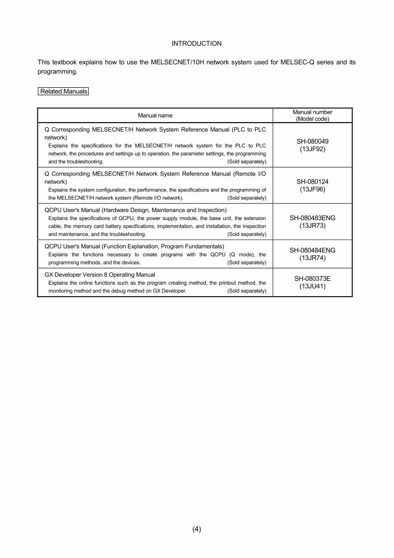
INTRODUCTION This textbook explains how to use the MELSECNET/10H network system used for MELSEC-Q series and its programming. Related Manuals
Manual name Manual number (Model code)
Q Corresponding MELSECNET/H Network System Reference Manual (PLC to PLC network)
Explains the specifications for the MELSECNET/H network system for the PLC to PLC network, the procedures and settings up to operation, the parameter settings, the programming and the troubleshooting. (Sold separately)
SH-080049 (13JF92)
Q Corresponding MELSECNET/H Network System Reference Manual (Remote I/O network)
Explains the system configuration, the performance, the specifications and the programming of the MELSECNET/H network system (Remote I/O network). (Sold separately)
SH-080124 (13JF96)
QCPU User's Manual (Hardware Design, Maintenance and Inspection) Explains the specifications of QCPU, the power supply module, the base unit, the extension cable, the memory card battery specifications, implementation, and installation, the inspection and maintenance, and the troubleshooting. (Sold separately)
SH-080483ENG (13JR73)
QCPU User's Manual (Function Explanation, Program Fundamentals) Explains the functions necessary to create programs with the QCPU (Q mode), the programming methods, and the devices. (Sold separately)
SH-080484ENG (13JR74)
GX Developer Version 8 Operating Manual Explains the online functions such as the program creating method, the printout method, the monitoring method and the debug method on GX Developer. (Sold separately)
SH-080373E (13JU41)
(5)
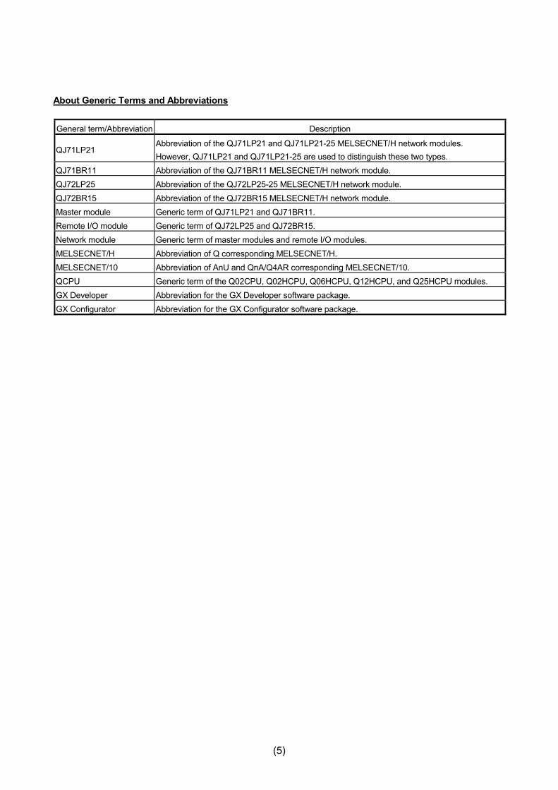
About Generic Terms and Abbreviations General term/Abbreviation Description
QJ71LP21 Abbreviation of the QJ71LP21 and QJ71LP21-25 MELSECNET/H network modules. However, QJ71LP21 and QJ71LP21-25 are used to distinguish these two types.
QJ71BR11 Abbreviation of the QJ71BR11 MELSECNET/H network module. QJ72LP25 Abbreviation of the QJ72LP25-25 MELSECNET/H network module. QJ72BR15 Abbreviation of the QJ72BR15 MELSECNET/H network module. Master module Generic term of QJ71LP21 and QJ71BR11. Remote I/O module Generic term of QJ72LP25 and QJ72BR15. Network module Generic term of master modules and remote I/O modules. MELSECNET/H Abbreviation of Q corresponding MELSECNET/H. MELSECNET/10 Abbreviation of AnU and QnA/Q4AR corresponding MELSECNET/10. QCPU Generic term of the Q02CPU, Q02HCPU, Q06HCPU, Q12HCPU, and Q25HCPU modules. GX Developer Abbreviation for the GX Developer software package. GX Configurator Abbreviation for the GX Configurator software package.

(6)
MEMO
1 - 1
1
CHAPTER 1 OVERVIEW
1.1 Overview
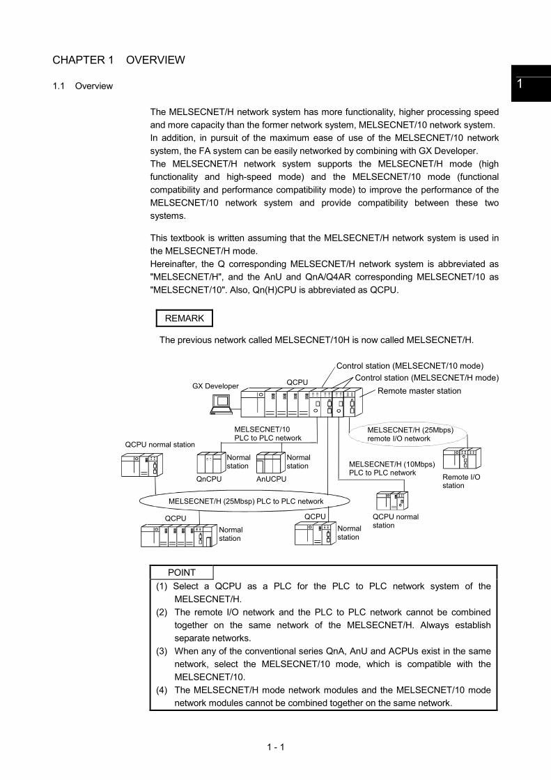
The MELSECNET/H network system has more functionality, higher processing speed and more capacity than the former network system, MELSECNET/10 network system. In addition, in pursuit of the maximum ease of use of the MELSECNET/10 network system, the FA system can be easily networked by combining with GX Developer. The MELSECNET/H network system supports the MELSECNET/H mode (high functionality and high-speed mode) and the MELSECNET/10 mode (functional compatibility and performance compatibility mode) to improve the performance of the MELSECNET/10 network system and provide compatibility between these two systems. This textbook is written assuming that the MELSECNET/H network system is used in the MELSECNET/H mode. Hereinafter, the Q corresponding MELSECNET/H network system is abbreviated as "MELSECNET/H", and the AnU and QnA/Q4AR corresponding MELSECNET/10 as "MELSECNET/10". Also, Qn(H)CPU is abbreviated as QCPU.
REMARK
The previous network called MELSECNET/10H is now called MELSECNET/H.
Remote master station
MELSECNET/H (25Mbsp) PLC to PLC network
Control station (MELSECNET/H mode)
MELSECNET/10PLC to PLC network
MELSECNET/H (25Mbps)remote I/O network
QCPU normal station
Remote I/O station
MELSECNET/H (10Mbps)PLC to PLC network
QCPU normal station
Control station (MELSECNET/10 mode)
Normal station
GX Developer QCPU
Normal station
QnCPU AnUCPU
Normal station
QCPUQCPU
Normal station
POINT
(1) Select a QCPU as a PLC for the PLC to PLC network system of the MELSECNET/H.
(2) The remote I/O network and the PLC to PLC network cannot be combined together on the same network of the MELSECNET/H. Always establish separate networks.
(3) When any of the conventional series QnA, AnU and ACPUs exist in the same network, select the MELSECNET/10 mode, which is compatible with the MELSECNET/10.
(4) The MELSECNET/H mode network modules and the MELSECNET/10 mode network modules cannot be combined together on the same network.
1 - 2
1.2 Features
The PLC to PLC network of MELSECNET/H is designed to provide higher processing speeds, more capacities, and more functionality while maintaining the connectivity with the MELSECNET/10; it is easier to use than ever in combination with GX Developer. Furthermore, the PLC to PLC network of MELSECNET/H has the following features that were not available with the conventional MELSECNET (II) and MELSECNET/B data link systems. (For the remote I/O network, refer to Chapter 5.) (1) Achievement of a high-speed communication system
(a) The MELSECNET/H enables high-speed communications with 25Mbps and 10Mbps communication speeds. (25Mbps for only optical loop system)
(b) The link scan time has become even faster through the use of processors
specifically designed for linking.
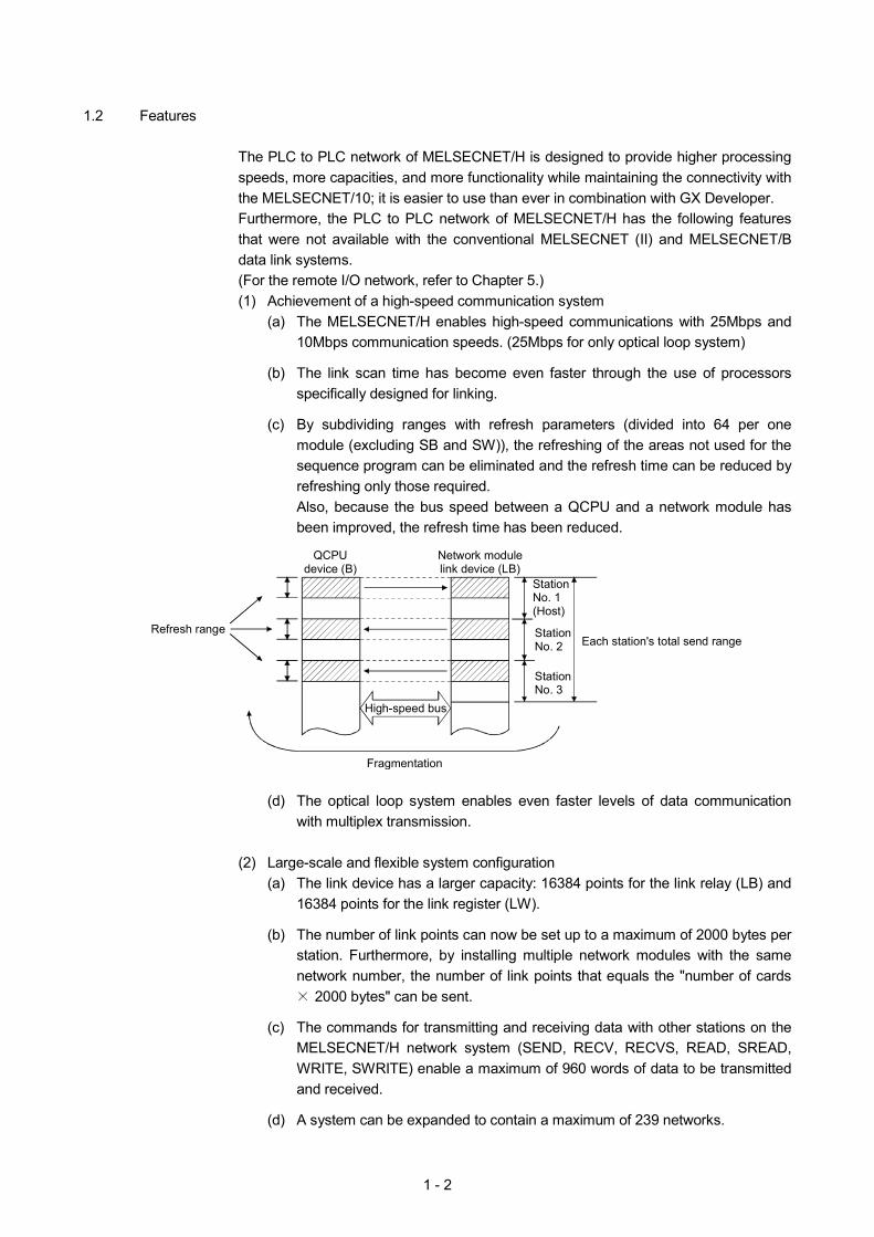
(c) By subdividing ranges with refresh parameters (divided into 64 per one module (excluding SB and SW)), the refreshing of the areas not used for the sequence program can be eliminated and the refresh time can be reduced by refreshing only those required. Also, because the bus speed between a QCPU and a network module has been improved, the refresh time has been reduced.
Refresh range
QCPUdevice (B)
StationNo. 1(Host)
StationNo. 2 Each station's total send range
Fragmentation
High-speed bus
Network modulelink device (LB)
StationNo. 3
(d) The optical loop system enables even faster levels of data communication
with multiplex transmission.
(2) Large-scale and flexible system configuration (a) The link device has a larger capacity: 16384 points for the link relay (LB) and
16384 points for the link register (LW).
(b) The number of link points can now be set up to a maximum of 2000 bytes per station. Furthermore, by installing multiple network modules with the same network number, the number of link points that equals the "number of cards
2000 bytes" can be sent.
(c) The commands for transmitting and receiving data with other stations on the MELSECNET/H network system (SEND, RECV, RECVS, READ, SREAD, WRITE, SWRITE) enable a maximum of 960 words of data to be transmitted and received.
(d) A system can be expanded to contain a maximum of 239 networks.
1 - 3
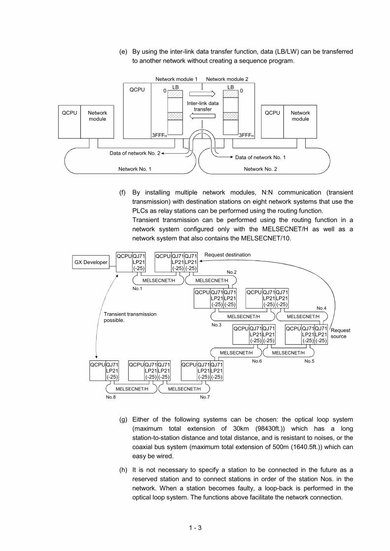
(e) By using the inter-link data transfer function, data (LB/LW) can be transferred
to another network without creating a sequence program.
Network No. 1
QCPU Networkmodule
0
Inter-link datatransfer
LBNetwork module 1
Data of network No. 2
3FFFH
QCPU
Network module 2LB 0
QCPU Networkmodule
3FFFH
Data of network No. 1
Network No. 2
(f) By installing multiple network modules, N:N communication (transient
transmission) with destination stations on eight network systems that use the PLCs as relay stations can be performed using the routing function. Transient transmission can be performed using the routing function in a network system configured only with the MELSECNET/H as well as a network system that also contains the MELSECNET/10.
QCPU QJ71
LP21(-25)
Transient transmission possible.
Request destination
Requestsource
GX Developer QJ71LP21(-25)
QJ71LP21(-25)
QCPU
MELSECNET/H
No.1
No.2
QJ71LP21(-25)
QJ71LP21(-25)
QCPU
MELSECNET/H
MELSECNET/H
MELSECNET/H
No.3
No.4
QJ71LP21(-25)
QJ71LP21(-25)
QCPU
MELSECNET/H MELSECNET/H
No.6 No.5
QJ71LP21(-25)
QJ71LP21(-25)
QCPU QJ71LP21(-25)
QJ71LP21(-25)
QCPU
MELSECNET/H MELSECNET/H
No.7No.8
QJ71LP21(-25)
QJ71LP21(-25)
QCPU QJ71LP21(-25)
QCPU QJ71LP21(-25)
QJ71LP21(-25)
QCPU
(g) Either of the following systems can be chosen: the optical loop system
(maximum total extension of 30km (98430ft.)) which has a long station-to-station distance and total distance, and is resistant to noises, or the coaxial bus system (maximum total extension of 500m (1640.5ft.)) which can easy be wired.
(h) It is not necessary to specify a station to be connected in the future as a
reserved station and to connect stations in order of the station Nos. in the network. When a station becomes faulty, a loop-back is performed in the optical loop system. The functions above facilitate the network connection.

1 - 4
(3) Providing various communication services
(a) The transient transmission can be performed by designating a channel number (1 to 64) of the receiving station. This function allows to set (change) the channel numbers arbitrarily with the sequence programs and to perform the transmission to multiple stations with the same channel number at one time.
Sender
Receiver channel No.9
Discard Acknowledged
Receiver channel unmatchedNetwork
moduleQCPU
Send
Destination channel No.9
No.1
Channel 1
2
ReceiveJ. SEND
MELSECNET/H
Receiver channel No.9
Receiver channel No.9
Receiver channel unmatched
Discard
Acknowledged
Acknowledged
NetworkmoduleQCPU
3
7
8
Channel
No.2
No.3
No.9
Channel
No.20
J. RECV
(b) By using the low-speed cyclic transmission function, it is possible to cyclically
send the data that does not require the high-speed transmission in a batch mode, separately from the normal cyclic transmission (LB/LW). The high-speed transmission can be achieved by efficiently dividing data to be transmitted into the data that requires the high-speed transmission, which is sent by the normal cyclic transmission, and the other data that is sent by the low-speed cyclic transmission. There are three types of transmission method depending on how the transmission is activated. 1) "Transmission of data for one station in one link scan" (default) 2) "Periodical cycle interval" which transmits in a set time cycle (h/min/s) 3) "System times" which transmits at the designated time
(year/month/day/h/min/s)
MELSECNET/H
Transmission at
the designated time
Low-speed cyclic transmission data
1 - 5
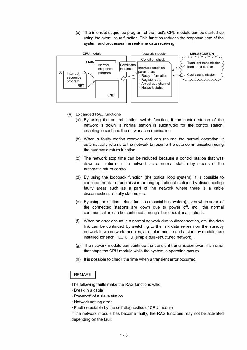
(c) The interrupt sequence program of the host's CPU module can be started up
using the event issue function. This function reduces the response time of the system and processes the real-time data receiving.
I50
CPU module
Transient transmission from other station
Cyclic transmission
MELSECNET/H
Normal sequence program
Condition check
Interrupt condition parameters
Relay informationRegister dataArrival at a channelNetwork status
Conditionsmatched
Interrupt sequence program
IRET
MAIN
END
Network module
(4) Expanded RAS functions
(a) By using the control station switch function, if the control station of the network is down, a normal station is substituted for the control station, enabling to continue the network communication.
(b) When a faulty station recovers and can resume the normal operation, it
automatically returns to the network to resume the data communication using the automatic return function.
(c) The network stop time can be reduced because a control station that was
down can return to the network as a normal station by means of the automatic return control.
(d) By using the loopback function (the optical loop system), it is possible to
continue the data transmission among operational stations by disconnecting faulty areas such as a part of the network where there is a cable disconnection, a faulty station, etc.
(e) By using the station detach function (coaxial bus system), even when some of
the connected stations are down due to power off, etc., the normal communication can be continued among other operational stations.
(f) When an error occurs in a normal network due to disconnection, etc. the data
link can be continued by switching to the link data refresh on the standby network if two network modules, a regular module and a standby module, are installed for each PLC CPU (simple dual-structured network).
(g) The network module can continue the transient transmission even if an error
that stops the CPU module while the system is operating occurs.
(h) It is possible to check the time when a transient error occurred.
REMARK
The following faults make the RAS functions valid. • Break in a cable • Power-off of a slave station • Network setting error • Fault detectable by the self-diagnostics of CPU module If the network module has become faulty, the RAS functions may not be activated depending on the fault.
1 - 6
(5) Enhancement and compatibility of the network functions
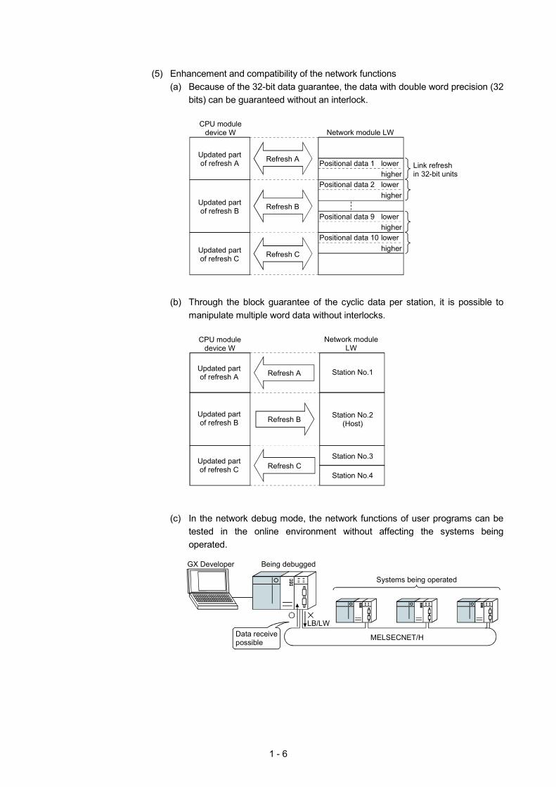
(a) Because of the 32-bit data guarantee, the data with double word precision (32 bits) can be guaranteed without an interlock.
Network module LWCPU module
device W
Refresh AUpdated part of refresh A Positional data 1 Link refresh
in 32-bit units lower higher
Positional data 2 lower higher
Positional data 9 lower higher
Positional data 10 lower higher
Refresh BUpdated part of refresh B
Refresh CUpdated part of refresh C
(b) Through the block guarantee of the cyclic data per station, it is possible to
manipulate multiple word data without interlocks.
Station No.1
Network moduleLW
CPU moduledevice W
Refresh A
Refresh B
Refresh C
Updated part of refresh A
Updated part of refresh B
Updated part of refresh C
Station No.3
Station No.4
Station No.2(Host)
(c) In the network debug mode, the network functions of user programs can be tested in the online environment without affecting the systems being operated.
MELSECNET/H
Systems being operated
Being debuggedGX Developer
Data receive possible
LB/LW
1 - 7
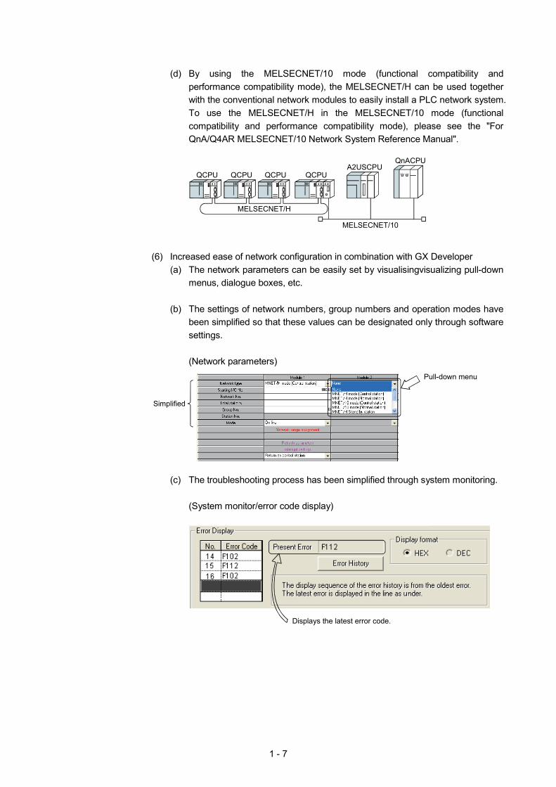
(d) By using the MELSECNET/10 mode (functional compatibility and
performance compatibility mode), the MELSECNET/H can be used together with the conventional network modules to easily install a PLC network system. To use the MELSECNET/H in the MELSECNET/10 mode (functional compatibility and performance compatibility mode), please see the "For QnA/Q4AR MELSECNET/10 Network System Reference Manual".
MELSECNET/H
QCPU
QCPU QCPU QCPUA2USCPU
QnACPU
MELSECNET/10
(6) Increased ease of network configuration in combination with GX Developer
(a) The network parameters can be easily set by visualisingvisualizing pull-down menus, dialogue boxes, etc.
(b) The settings of network numbers, group numbers and operation modes have
been simplified so that these values can be designated only through software settings.
(Network parameters)
Pull-down menu
Simplified
(c) The troubleshooting process has been simplified through system monitoring.
(System monitor/error code display)
Displays the latest error code.
1 - 8
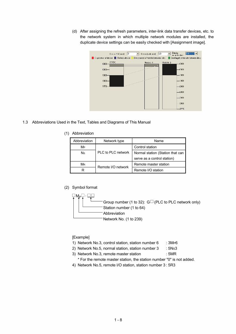
(d) After assigning the refresh parameters, inter-link data transfer devices, etc. to
the network system in which multiple network modules are installed, the duplicate device settings can be easily checked with [Assignment image].
1.3 Abbreviations Used in the Text, Tables and Diagrams of This Manual
(1) Abbreviation
Abbreviation Network type Name
MP Control station NS PLC to PLC network Normal station (Station that can
serve as a control station) MR Remote master station R
Remote I/O network Remote I/O station
(2) Symbol format
[Example] 1) Network No.3, control station, station number 6 : 3MP6 2) Network No.5, normal station, station number 3 : 5NS3 3) Network No.3, remote master station : 5MR
* For the remote master station, the station number "0" is not added. 4) Network No.5, remote I/O station, station number 3 : 5R3
Group number (1 to 32): G (PLC to PLC network only)Station number (1 to 64)AbbreviationNetwork No. (1 to 239)
M P -
1 - 9
1.4 System Configuration of PLC to PLC Network
This section explains different system configurations that are available with the PLC to PLC network of the MELSECNET/H.
REMARK
The following functions are changed or added in the function version B of network module.
(1) Functions added Function Description
Multiple CPU system supported
Multiple CPU systems are supported.
Addition of special link instructions (4 instructions)
RRUN instruction (Remote RUN instruction) RSTOP instruction (Remote STOP instruction) RTMRD instruction (Other station's clock data read instruction) RTMWR instruction (Other station's clock data write instruction)
(2) Functions changed
Function Description
Data length of special link instructions increased to 960 words
The data length of the following special link instructions was increased from 480 words to 960 words. Target dedicated instructions: SEND, RECV, RECVS, READ, SREAD, WRITE, SWRITE
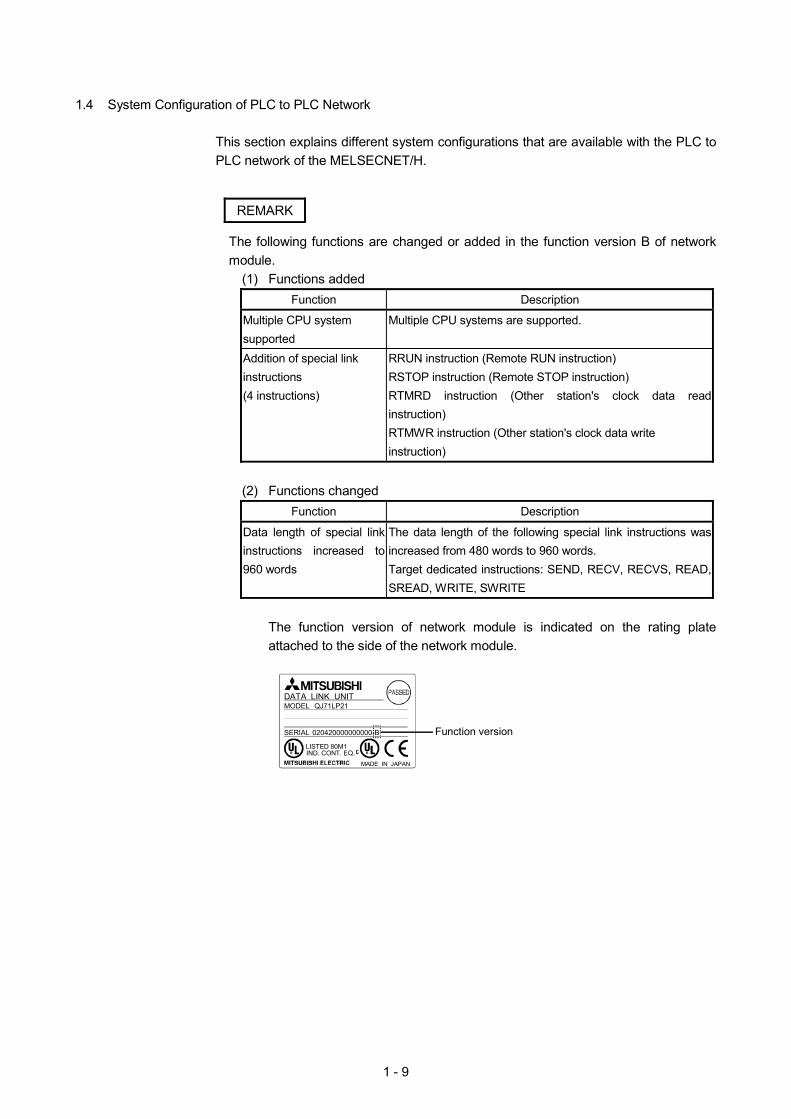
The function version of network module is indicated on the rating plate attached to the side of the network module.
MADE IN JAPAN
LISTED 80M1IND. CONT. EQ.
DATA LINK UNITMODEL QJ71LP21
SERIAL 020420000000000-B Function version
1 - 10
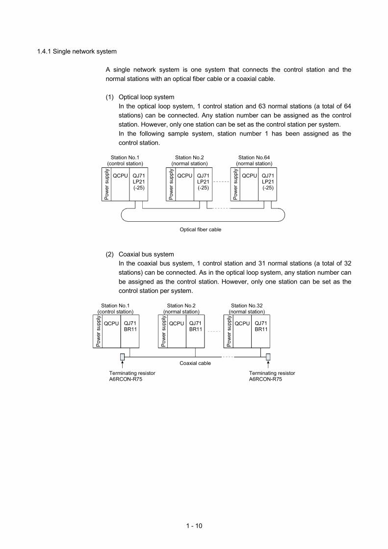
1.4.1 Single network system
A single network system is one system that connects the control station and the normal stations with an optical fiber cable or a coaxial cable.
(1) Optical loop system
In the optical loop system, 1 control station and 63 normal stations (a total of 64 stations) can be connected. Any station number can be assigned as the control station. However, only one station can be set as the control station per system. In the following sample system, station number 1 has been assigned as the control station.
Optical fiber cable
QCPU
Pow
er s
uppl
y
QJ71LP21(-25)
Station No.1(control station)
Station No.64(normal station)
Station No.2(normal station)
QCPU QJ71LP21(-25)
QCPU QJ71LP21(-25)
Pow
er s
uppl
y
Pow
er s
uppl
y
(2) Coaxial bus system
In the coaxial bus system, 1 control station and 31 normal stations (a total of 32 stations) can be connected. As in the optical loop system, any station number can be assigned as the control station. However, only one station can be set as the control station per system.
Station No.2
(normal station)
QCPU
Station No.1(control station)
Terminating resistorA6RCON-R75
Coaxial cable
Station No.32(normal station)
QJ71BR11
QCPU QJ71BR11
QCPU QJ71BR11
Terminating resistorA6RCON-R75
1 - 11
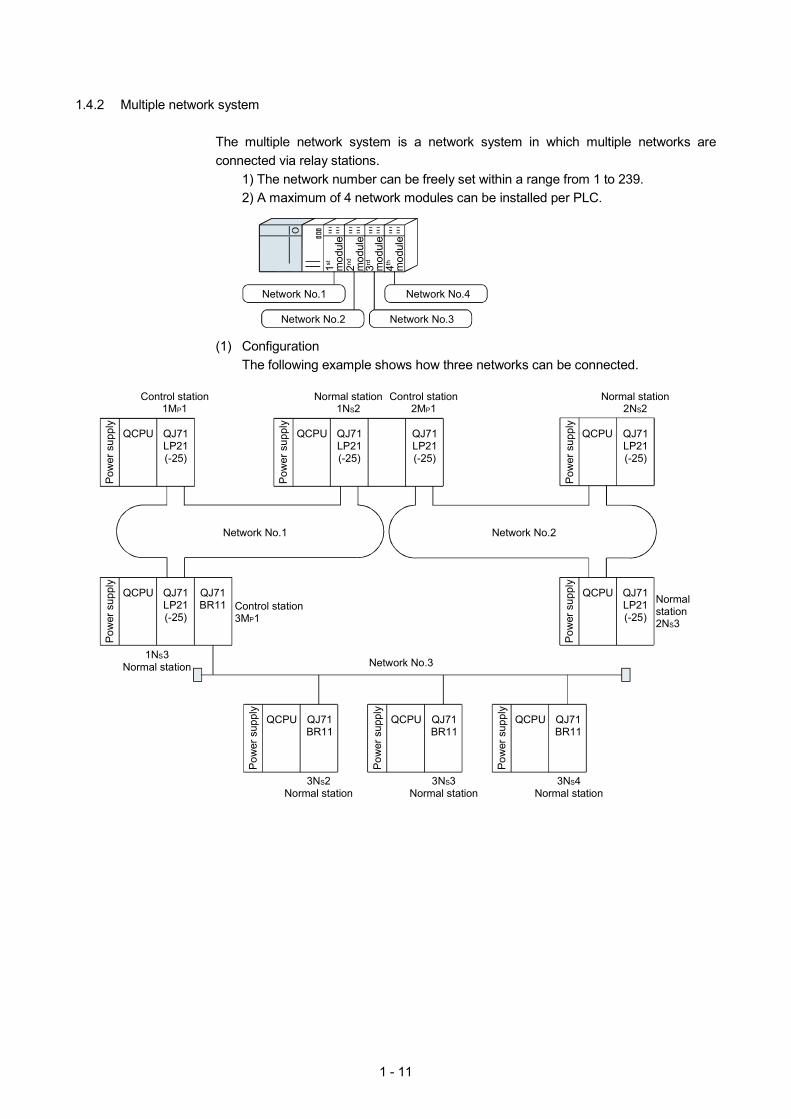
1.4.2 Multiple network system
The multiple network system is a network system in which multiple networks are connected via relay stations.
1) The network number can be freely set within a range from 1 to 239. 2) A maximum of 4 network modules can be installed per PLC.
1st
mod
ule
Network No.1
Network No.2
Network No.4
Network No.3
2nd
mod
ule
3rd
mod
ule
4th
mod
ule
(1) Configuration The following example shows how three networks can be connected.
Network No.1
Pow
er s
uppl
y
Control station1MP1
QJ71LP21(-25)
QCPU
Pow
er s
uppl
y
QJ71LP21(-25)
QCPU QJ71LP21(-25)
Control station2MP1
Normal station1NS2
Pow
er s
uppl
y
QCPU QJ71LP21(-25)
Normal station2NS2
Network No.2
Network No.3
Control station3MP1
Pow
er s
uppl
y
QJ71LP21(-25)
QCPU QJ71BR11
1NS3Normal station
Pow
er s
uppl
y
QJ71LP21(-25)
QCPU Normalstation2NS3
Pow
er s
uppl
y
QCPU QJ71BR11
3NS2Normal station
Pow
er s
uppl
y
QCPU QJ71BR11
3NS3Normal station
Pow
er s
uppl
y
QCPU QJ71BR11
3NS4Normal station
1 - 12
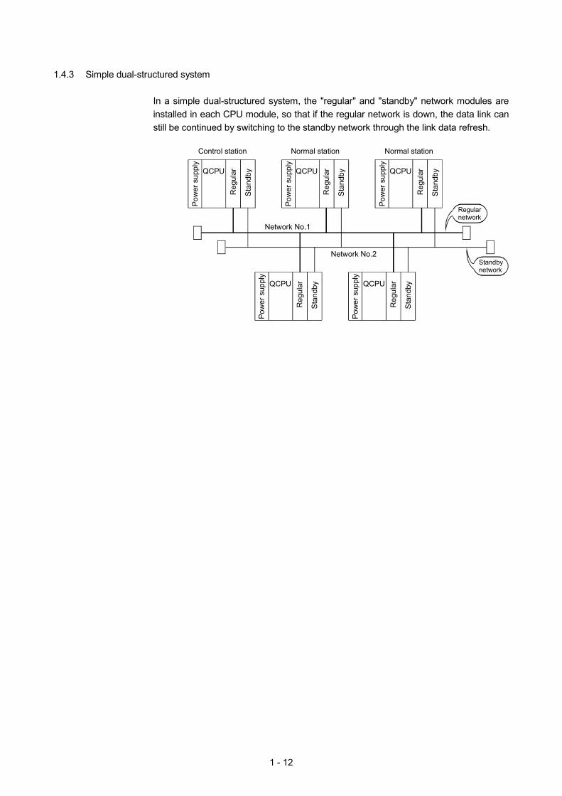
1.4.3 Simple dual-structured system
In a simple dual-structured system, the "regular" and "standby" network modules are installed in each CPU module, so that if the regular network is down, the data link can still be continued by switching to the standby network through the link data refresh.
Network No.1
Control station Normal station
Reg
ular
Sta
ndbyQCPU
Pow
er s
uppl
y
Regularnetwork
Standbynetwork
Normal station
Reg
ular
Sta
ndbyQCPU
Pow
er s
uppl
y
Reg
ular
Sta
ndbyQCPU
Pow
er s
uppl
y
Network No.2
Reg
ular
Sta
ndbyQCPU
Pow
er s
uppl
y
Reg
ular
Sta
ndbyQCPU
Pow
er s
uppl
y
1 - 13
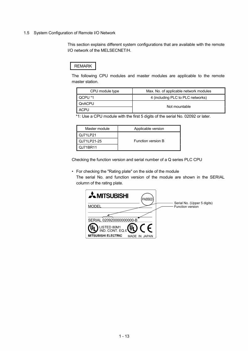
1.5 System Configuration of Remote I/O Network
This section explains different system configurations that are available with the remote I/O network of the MELSECNET/H.
REMARK
The following CPU modules and master modules are applicable to the remote master station.
CPU module type Max. No. of applicable network modules
QCPU *1 4 (including PLC to PLC networks) QnACPU ACPU
Not mountable
*1: Use a CPU module with the first 5 digits of the serial No. 02092 or later.
Master module Applicable version
QJ71LP21 QJ71LP21-25 QJ71BR11
Function version B
Checking the function version and serial number of a Q series PLC CPU
• For checking the "Rating plate" on the side of the module
The serial No. and function version of the module are shown in the SERIAL column of the rating plate.
MADE IN JAPAN
LISTED 80M1IND. CONT. EQ.
MODEL
SERIAL 020920000000000-B
Serial No. (Upper 5 digits)Function version
1 - 14
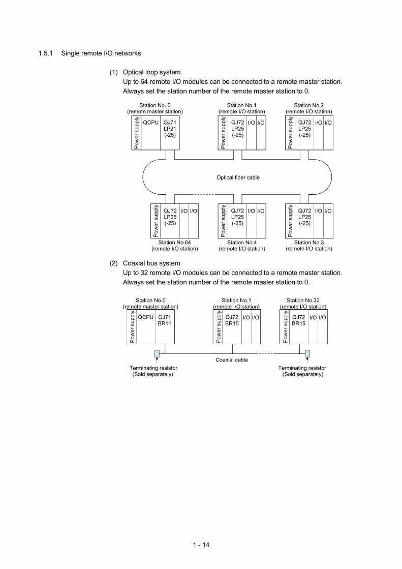
1.5.1 Single remote I/O networks
(1) Optical loop system Up to 64 remote I/O modules can be connected to a remote master station. Always set the station number of the remote master station to 0.
Pow
er s
uppl
y
QCPU QJ71LP21(-25)
Station No. 0(remote master station)
Station No.1(remote I/O station)
I/O
Optical fiber cable
Station No.2(remote I/O station)
Pow
er s
uppl
y
QJ72LP25(-25)
I/O I/O
Pow
er s
uppl
y
QJ72LP25(-25)
I/O
I/O
Pow
er s
uppl
y
QJ72LP25(-25)
I/O
Station No.64(remote I/O station)
Station No.4(remote I/O station)
Station No.3(remote I/O station)
I/O
Pow
er s
uppl
y
QJ72LP25(-25)
I/O I/O
Pow
er s
uppl
y
QJ72LP25(-25)
I/O
(2) Coaxial bus system
Up to 32 remote I/O modules can be connected to a remote master station. Always set the station number of the remote master station to 0.
QCPU
Station No.0(remote master station)
Station No.1(remote I/O station)
I/O
Terminating resistor(Sold separately)
Coaxial cable
Station No.32(remote I/O station)
QJ71BR11
QJ72BR15
I/O I/OQJ72BR15
I/O
Terminating resistor(Sold separately)
1 - 15
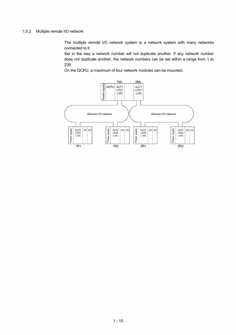
1.5.2 Multiple remote I/O network
The multiple remote I/O network system is a network system with many networks connected to it. Set in the way a network number will not duplicate another. If any network number dose not duplicate another, the network numbers can be set within a range from 1 to 239. On the QCPU, a maximum of four network modules can be mounted.
Remote I/O network
Pow
er s
uppl
y
QCPU
1MR
I/O
1R1
QJ71LP21(-25)
QJ71LP21(-25)
2MR
Remote I/O network
Pow
er s
uppl
y QJ72LP25(-25)
I/O I/O
Pow
er s
uppl
y QJ72LP25(-25)
I/O I/O
Pow
er s
uppl
y QJ72LP25(-25)
I/O I/O
Pow
er s
uppl
y QJ72LP25(-25)
I/O
1R2 2R1 2R2

1 - 16
MEMO
2 - 1
2
CHAPTER 2 EXERCISE ITEMS, PARAMETERS, AND SETUP AND PROCEDURES BEFORE STARTING THE OPERATION
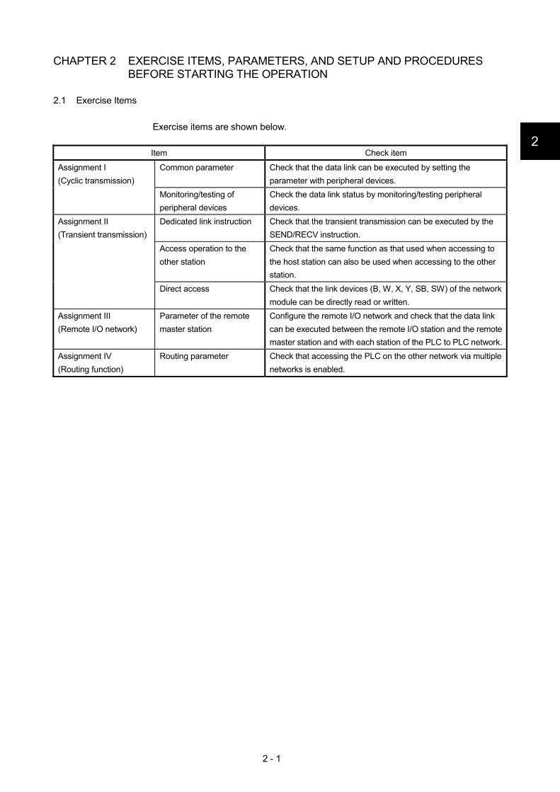
2.1 Exercise Items
Exercise items are shown below.
Item Check item
Common parameter Check that the data link can be executed by setting the parameter with peripheral devices.
Assignment I (Cyclic transmission)
Monitoring/testing of peripheral devices
Check the data link status by monitoring/testing peripheral devices.
Dedicated link instruction Check that the transient transmission can be executed by the SEND/RECV instruction.
Access operation to the other station
Check that the same function as that used when accessing to the host station can also be used when accessing to the other station.
Assignment II (Transient transmission)
Direct access Check that the link devices (B, W, X, Y, SB, SW) of the network module can be directly read or written.
Assignment III (Remote I/O network)
Parameter of the remote master station
Configure the remote I/O network and check that the data link can be executed between the remote I/O station and the remote master station and with each station of the PLC to PLC network.
Assignment IV (Routing function)
Routing parameter Check that accessing the PLC on the other network via multiple networks is enabled.
2 – 2
2.2 Types of Parameters
To run the MELSECNET/H, the parameters for the network module loaded to the PLC CPU must be set with GX Developer. In the parameter setting, settings from the selection of MELSECNET/H until the setting of application function details can be performed. The following shows the setting screens of each parameter. (Setting descriptions are examples.)
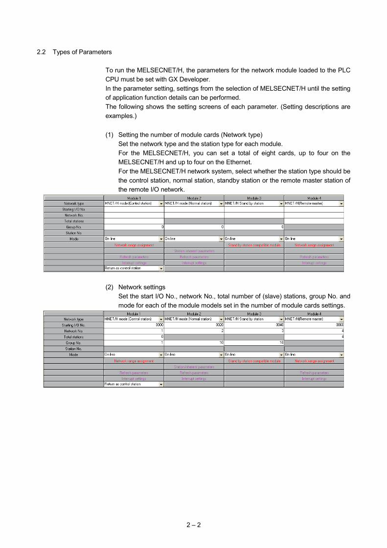
(1) Setting the number of module cards (Network type)
Set the network type and the station type for each module. For the MELSECNET/H, you can set a total of eight cards, up to four on the MELSECNET/H and up to four on the Ethernet. For the MELSECNET/H network system, select whether the station type should be the control station, normal station, standby station or the remote master station of the remote I/O network.
(2) Network settings
Set the start I/O No., network No., total number of (slave) stations, group No. and mode for each of the module models set in the number of module cards settings.
2 – 3
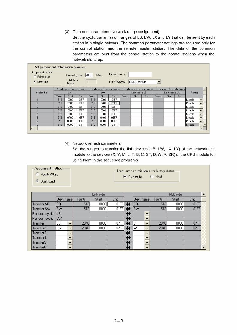
(3) Common parameters (Network range assignment)
Set the cyclic transmission ranges of LB, LW, LX and LY that can be sent by each station in a single network. The common parameter settings are required only for the control station and the remote master station. The data of the common parameters are sent from the control station to the normal stations when the network starts up.
(4) Network refresh parameters
Set the ranges to transfer the link devices (LB, LW, LX, LY) of the network link module to the devices (X, Y, M, L, T, B, C, ST, D, W, R, ZR) of the CPU module for using them in the sequence programs.
2 – 4
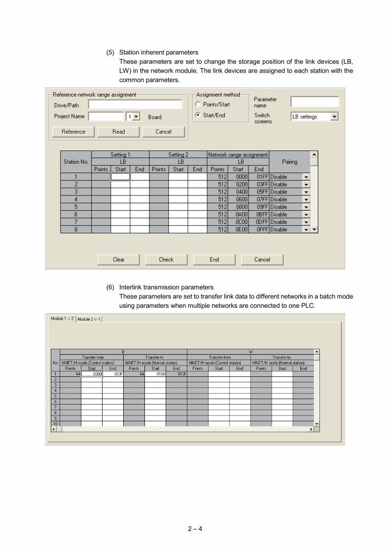
(5) Station inherent parameters
These parameters are set to change the storage position of the link devices (LB, LW) in the network module. The link devices are assigned to each station with the common parameters.
(6) Interlink transmission parameters
These parameters are set to transfer link data to different networks in a batch mode using parameters when multiple networks are connected to one PLC.
2 – 5
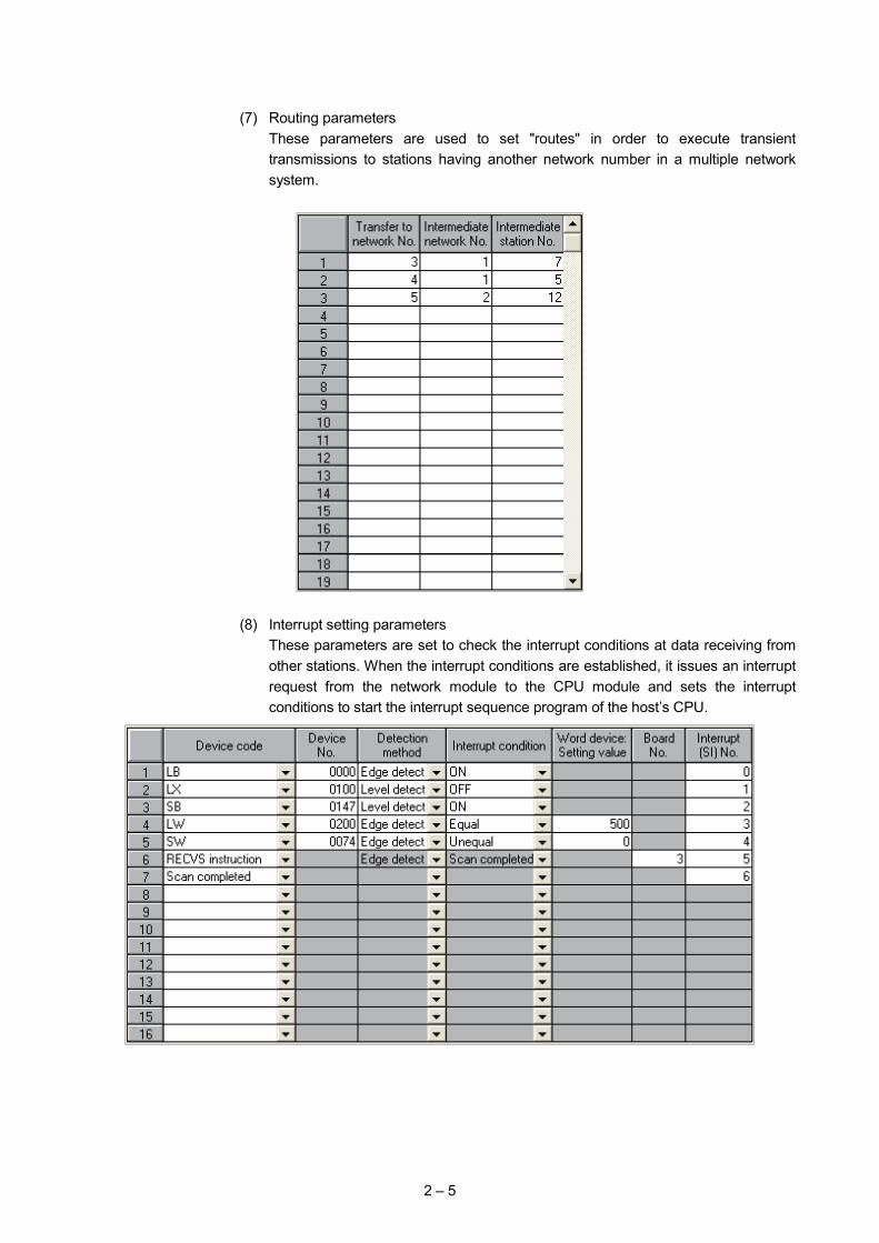
(7) Routing parameters
These parameters are used to set "routes" in order to execute transient transmissions to stations having another network number in a multiple network system.
(8) Interrupt setting parameters
These parameters are set to check the interrupt conditions at data receiving from other stations. When the interrupt conditions are established, it issues an interrupt request from the network module to the CPU module and sets the interrupt conditions to start the interrupt sequence program of the host’s CPU.
2 – 6
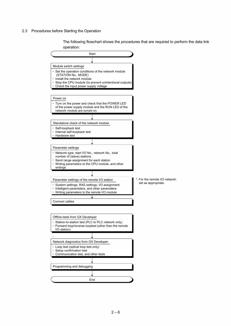
2.3 Procedures before Starting the Operation
The following flowchart shows the procedures that are required to perform the data link operation:
Parameter settings of the remote I/O stationSystem settings, RAS settings, I/O assignmentIntelligent parameters, and other parametersWriting parameters to the remote I/O module
Start
Power on
Turn on the power and check that the POWER LED of the power supply module and the RUN LED of the network module are turned on.
Standalone check of the network moduleSelf-loopback testInternal self-loopback testHardware test
Module switch settings
Set the operation conditions of the network module (STATION No., MODE)Install the network moduleStop the CPU module (to prevent unintentional outputs)Check the input power supply voltage
Parameter settings
Network type, start I/O No., network No., total number of (slave) stationsSend range assignment for each stationWriting parameters to the CPU module, and other writings
End
Programming and debugging
Offline tests from GX DeveloperStation-to-station test (PLC to PLC network only)Forward loop/reverse looptest (other than the remote I/O station)
Network diagnostics from GX DeveloperLoop test (optical loop test only)Setup confirmation testCommunication test, and other tests
Connect cables
*: For the remote I/O network, set as appropriate.
3 - 1
3
CHAPTER 3 ASSIGNMENT I (CYCLIC TRANSMISSION)
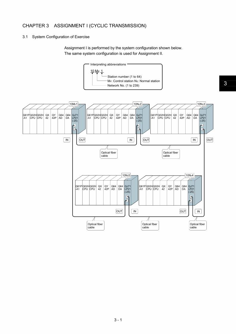
3.1 System Configuration of Exercise
Assignment I is performed by the system configuration shown below. The same system configuration is used for Assignment II.
Interpreting abbreviations
10 MP 1Station number (1 to 64)MP: Control station NS: Normal stationNetwork No. (1 to 239)
10MP1
OUT OUTIN OUTIN
OUT IN OUT IN
IN
Optical fiber cable
QJ71LP21(-25)
Q64DA
Q64AD
QY42P
Q02HCPU
Q02HCPU
QX42
Q61P-A1
QJ71LP21(-25)
Q64DA
Q64AD
QY42P
Q02HCPU
Q02HCPU
QX42
Q61P-A1
QJ71LP21(-25)
Q64DA
Q64AD
QY42P
Q02HCPU
Q02HCPU
QX42
Q61P-A1
QJ71LP21(-25)
Q64DA
Q64AD
QY42P
Q02HCPU
Q02HCPU
QX42
Q61P-A1
QJ71LP21(-25)
Q64DA
Q64AD
QY42P
Q02HCPU
Q02HCPU
QX42
Q61P-A1
10NS2 10NS3
Optical fiber cable
Optical fiber cable
Optical fiber cable
Optical fiber cable
10NS5 10NS4
3 - 2
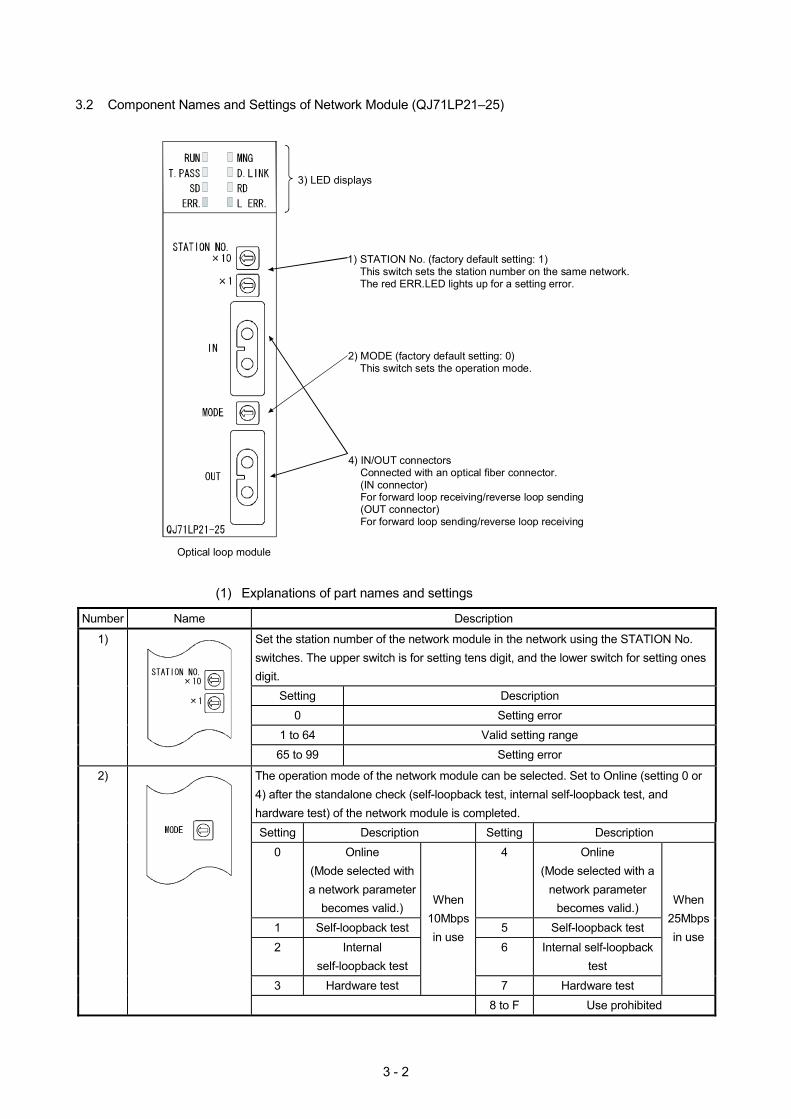
3.2 Component Names and Settings of Network Module (QJ71LP21–25)
3) LED displays
1) STATION No. (factory default setting: 1)This switch sets the station number on the same network.The red ERR.LED lights up for a setting error.
2) MODE (factory default setting: 0)This switch sets the operation mode.
4) IN/OUT connectorsConnected with an optical fiber connector.(IN connector)For forward loop receiving/reverse loop sending(OUT connector)For forward loop sending/reverse loop receiving
Optical loop module
(1) Explanations of part names and settings
Number Name Description
Set the station number of the network module in the network using the STATION No. switches. The upper switch is for setting tens digit, and the lower switch for setting ones digit.
Setting Description 0 Setting error
1 to 64 Valid setting range
1)
65 to 99 Setting error
The operation mode of the network module can be selected. Set to Online (setting 0 or 4) after the standalone check (self-loopback test, internal self-loopback test, and hardware test) of the network module is completed. Setting Description Setting Description
0 Online (Mode selected with a network parameter
becomes valid.)
4 Online (Mode selected with a
network parameter becomes valid.)
1 Self-loopback test 5 Self-loopback test 2 Internal
self-loopback test 6 Internal self-loopback
test 3 Hardware test
When 10Mbps in use
7 Hardware test
When 25Mbps in use
2)
8 to F Use prohibited
3 - 3
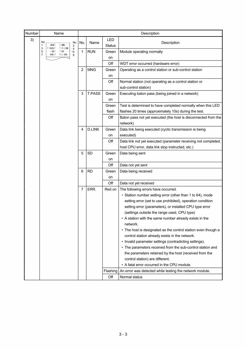
Number Name Description
No. Name LED
Status Description
1 RUN Green on
Module operating normally
Off WDT error occurred (hardware error) 2 MNG Green
on Operating as a control station or sub-control station
Off Normal station (not operating as a control station or sub-control station)
3 T.PASS Green on
Executing baton pass (being joined in a network)
Green flash
Test is determined to have completed normally when this LED flashes 20 times (approximately 10s) during the test.
Off Baton pass not yet executed (the host is disconnected from the network)
4 D.LINK Green on
Data link being executed (cyclic transmission is being executed)
Off Data link not yet executed (parameter receiving not completed, host CPU error, data link stop instructed, etc.)
5 SD Green on
Data being sent
Off Data not yet sent 6 RD Green
on Data being received
Off Data not yet received Red on The following errors have occurred.
• Station number setting error (other than 1 to 64), mode setting error (set to use prohibited), operation condition setting error (parameters), or installed CPU type error (settings outside the range used, CPU type)
• A station with the same number already exists in the network.
• The host is designated as the control station even though a control station already exists in the network.
• Invalid parameter settings (contradicting settings). • The parameters received from the sub-control station and
the parameters retained by the host (received from the control station) are different.
• A fatal error occurred in the CPU module. Flashing An error was detected while testing the network module.
3) No2468
No1357
7 ERR.
Off Normal status

3 - 4
Number Name Description
8 L ERR. Red on A communication error occurred. (One of the following communication errors has occurred): CRC : Error generated by an abnormal cable, noise, etc. OVER : This error occurs when the next data is received
before the last receive data is loaded into the module, and the data is overwritten. It is caused by a hardware error in the receive area of the network module.
AB.IF : This error occurs when more than the specified number of bits are set to "1" among the receive data in the frame, or when the receive data is shorter than the specified data length.
TIME : This error occurs when a baton pass was not handed to the host within the monitoring time.
DATA : This error is caused when abnormal code data is received.
UNDER : This error occurs when the internal processing of the send data was not executed at a fixed interval.
LOOP : This error occurs when the forward or reverse loop line is faulty and the power to the adjacent station, which sends data to the host station, is turned OFF or the cable connector is faulty.
<Corrective action> Check the cables and connectors. (Detached or loosened connectors, wrong IN/OUT connections, broken or damaged cables, improper cable routing, etc.)
3) No2468
No1357
Off No communication error
3 - 5
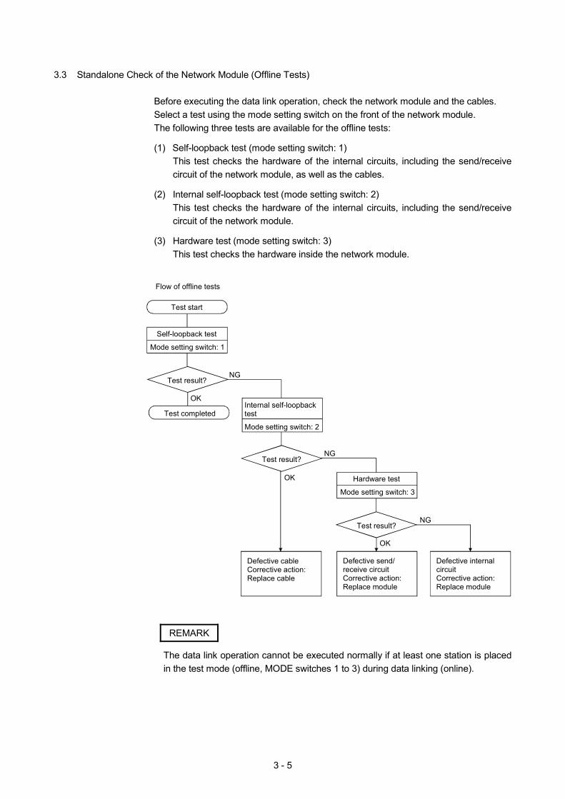
3.3 Standalone Check of the Network Module (Offline Tests)
Before executing the data link operation, check the network module and the cables. Select a test using the mode setting switch on the front of the network module. The following three tests are available for the offline tests:
(1) Self-loopback test (mode setting switch: 1)
This test checks the hardware of the internal circuits, including the send/receive circuit of the network module, as well as the cables.
(2) Internal self-loopback test (mode setting switch: 2)
This test checks the hardware of the internal circuits, including the send/receive circuit of the network module.
(3) Hardware test (mode setting switch: 3)
This test checks the hardware inside the network module.
Test start
Self-loopback test
Mode setting switch: 1
Test result?
Test completedInternal self-loopback test
Mode setting switch: 2
Test result?
Hardware test
Mode setting switch: 3
Test result?
Defective send/receive circuitCorrective action:Replace module
Defective cable Corrective action:Replace cable
Defective internalcircuitCorrective action:Replace module
NG
NG
NG
OK
OK
OK
Flow of offline tests
REMARK
The data link operation cannot be executed normally if at least one station is placed in the test mode (offline, MODE switches 1 to 3) during data linking (online).
3 - 6
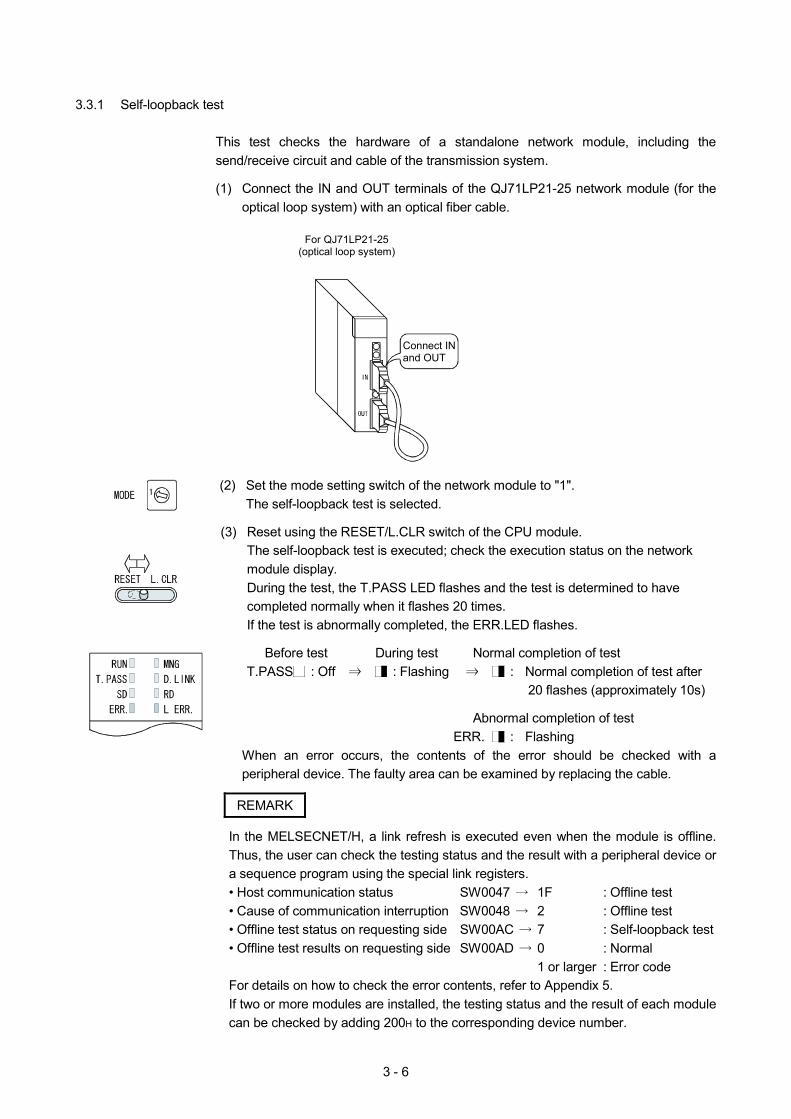
3.3.1 Self-loopback test
This test checks the hardware of a standalone network module, including the send/receive circuit and cable of the transmission system.
(1) Connect the IN and OUT terminals of the QJ71LP21-25 network module (for the
optical loop system) with an optical fiber cable.
For QJ71LP21-25(optical loop system)
Connect IN and OUT
(2) Set the mode setting switch of the network module to "1". The self-loopback test is selected.
(3) Reset using the RESET/L.CLR switch of the CPU module. The self-loopback test is executed; check the execution status on the network module display. During the test, the T.PASS LED flashes and the test is determined to have completed normally when it flashes 20 times. If the test is abnormally completed, the ERR.LED flashes.
Before test During test Normal completion of test T.PASS : Off : Flashing : Normal completion of test after
20 flashes (approximately 10s) Abnormal completion of test ERR. : Flashing
When an error occurs, the contents of the error should be checked with a peripheral device. The faulty area can be examined by replacing the cable.
REMARK
In the MELSECNET/H, a link refresh is executed even when the module is offline. Thus, the user can check the testing status and the result with a peripheral device or a sequence program using the special link registers. • Host communication status SW0047 1F : Offline test • Cause of communication interruption SW0048 2 : Offline test • Offline test status on requesting side SW00AC 7 : Self-loopback test • Offline test results on requesting side SW00AD 0 : Normal 1 or larger : Error code For details on how to check the error contents, refer to Appendix 5. If two or more modules are installed, the testing status and the result of each module can be checked by adding 200H to the corresponding device number.
3 - 7
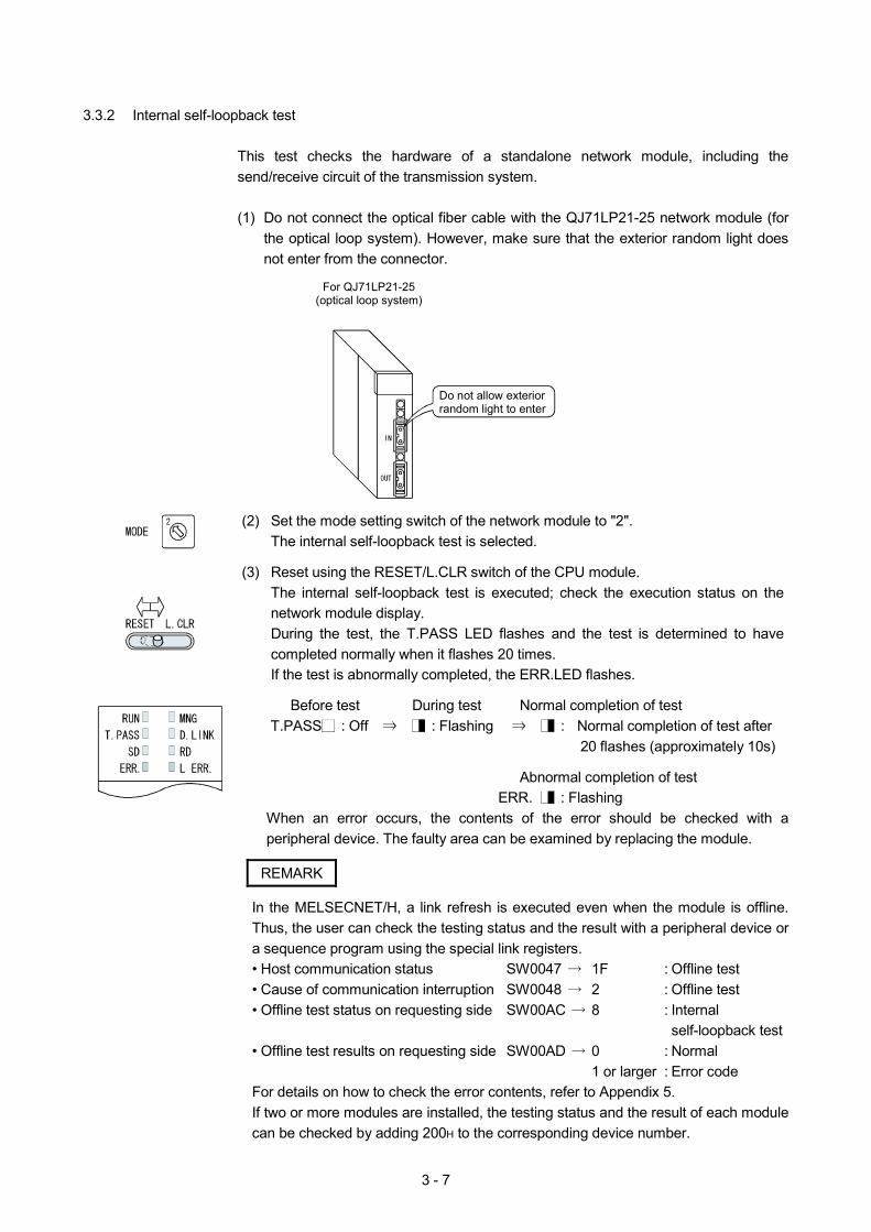
3.3.2 Internal self-loopback test
This test checks the hardware of a standalone network module, including the send/receive circuit of the transmission system.
(1) Do not connect the optical fiber cable with the QJ71LP21-25 network module (for
the optical loop system). However, make sure that the exterior random light does not enter from the connector.
For QJ71LP21-25
(optical loop system)
Do not allow exterior random light to enter
(2) Set the mode setting switch of the network module to "2". The internal self-loopback test is selected.
(3) Reset using the RESET/L.CLR switch of the CPU module. The internal self-loopback test is executed; check the execution status on the network module display. During the test, the T.PASS LED flashes and the test is determined to have completed normally when it flashes 20 times. If the test is abnormally completed, the ERR.LED flashes.
Before test During test Normal completion of test T.PASS : Off : Flashing : Normal completion of test after
20 flashes (approximately 10s) Abnormal completion of test ERR. : Flashing
When an error occurs, the contents of the error should be checked with a peripheral device. The faulty area can be examined by replacing the module.
REMARK
In the MELSECNET/H, a link refresh is executed even when the module is offline. Thus, the user can check the testing status and the result with a peripheral device or a sequence program using the special link registers. • Host communication status SW0047 1F : Offline test • Cause of communication interruption SW0048 2 : Offline test • Offline test status on requesting side SW00AC 8 : Internal
self-loopback test • Offline test results on requesting side SW00AD 0 : Normal 1 or larger : Error code For details on how to check the error contents, refer to Appendix 5. If two or more modules are installed, the testing status and the result of each module can be checked by adding 200H to the corresponding device number.
3 - 8
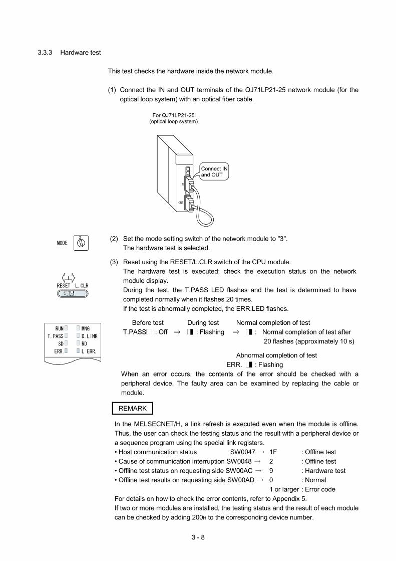
3.3.3 Hardware test
This test checks the hardware inside the network module.
(1) Connect the IN and OUT terminals of the QJ71LP21-25 network module (for the optical loop system) with an optical fiber cable.
For QJ71LP21-25
(optical loop system)
Connect IN and OUT
(2) Set the mode setting switch of the network module to "3".
The hardware test is selected.
(3) Reset using the RESET/L.CLR switch of the CPU module. The hardware test is executed; check the execution status on the network module display. During the test, the T.PASS LED flashes and the test is determined to have completed normally when it flashes 20 times. If the test is abnormally completed, the ERR.LED flashes.
Before test During test Normal completion of test T.PASS : Off : Flashing : Normal completion of test after
20 flashes (approximately 10 s) Abnormal completion of test ERR. : Flashing
When an error occurs, the contents of the error should be checked with a peripheral device. The faulty area can be examined by replacing the cable or module.
REMARK
In the MELSECNET/H, a link refresh is executed even when the module is offline. Thus, the user can check the testing status and the result with a peripheral device or a sequence program using the special link registers. • Host communication status SW0047 1F : Offline test • Cause of communication interruption SW0048 2 : Offline test • Offline test status on requesting side SW00AC 9 : Hardware test • Offline test results on requesting side SW00AD 0 : Normal 1 or larger : Error code For details on how to check the error contents, refer to Appendix 5. If two or more modules are installed, the testing status and the result of each module can be checked by adding 200H to the corresponding device number.
3 - 9
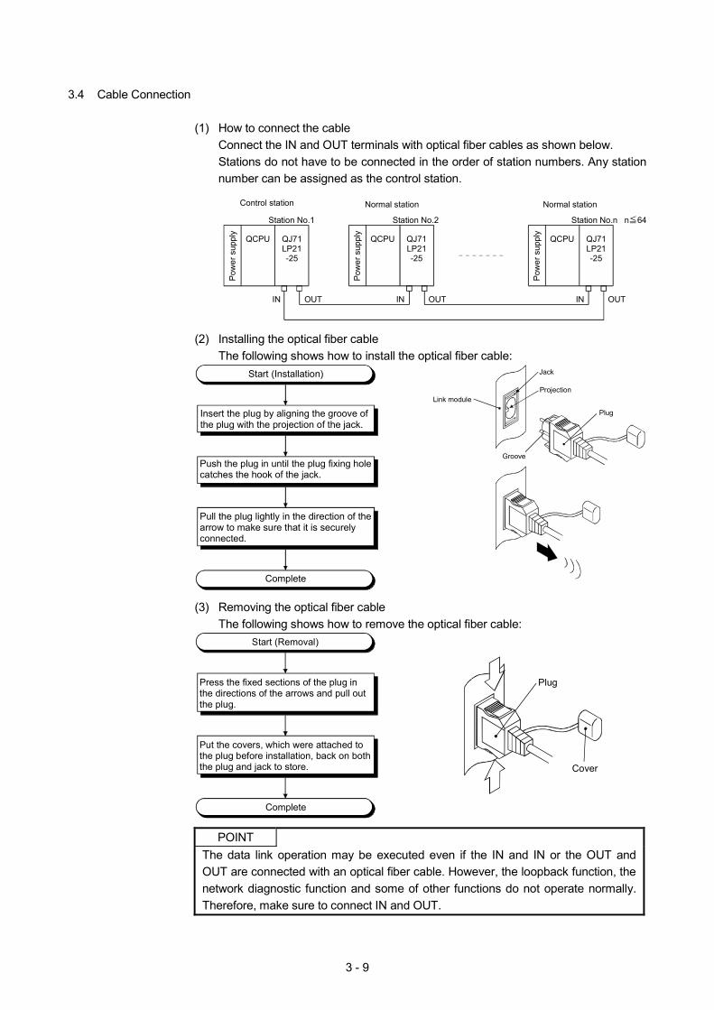
3.4 Cable Connection
(1) How to connect the cable Connect the IN and OUT terminals with optical fiber cables as shown below. Stations do not have to be connected in the order of station numbers. Any station number can be assigned as the control station.
QCPUP
ower
sup
ply
Control station
IN OUT
Station No.1
Normal station
n 64
Normal station
QJ71LP21-25
QCPU
Pow
er s
uppl
y
QJ71LP21-25
QCPU
Pow
er s
uppl
y
QJ71LP21-25
Station No.2 Station No.n
IN OUT IN OUT
(2) Installing the optical fiber cable
The following shows how to install the optical fiber cable:
Complete
Start (Installation)
Insert the plug by aligning the groove of the plug with the projection of the jack.
Push the plug in until the plug fixing hole catches the hook of the jack.
Pull the plug lightly in the direction of the arrow to make sure that it is securely connected.
Jack
Projection
Groove
Plug
Link module
(3) Removing the optical fiber cable
The following shows how to remove the optical fiber cable:
Press the fixed sections of the plug in the directions of the arrows and pull out the plug.
Complete
Start (Removal)
Put the covers, which were attached to the plug before installation, back on both the plug and jack to store.
Plug
Cover
POINT
The data link operation may be executed even if the IN and IN or the OUT and OUT are connected with an optical fiber cable. However, the loopback function, the network diagnostic function and some of other functions do not operate normally. Therefore, make sure to connect IN and OUT.
3 - 10
3.5 Write Operation to CPU Module
This section explains the operation from reading the program from a floppy disk to writing it to the CPU module.
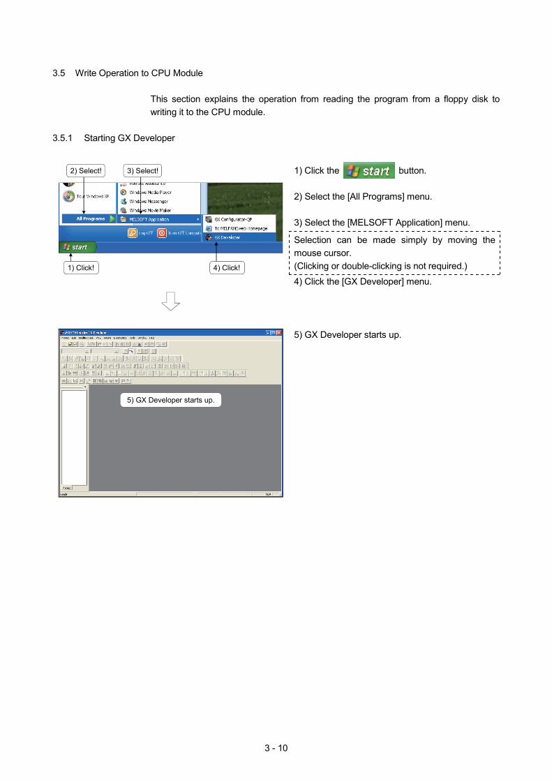
3.5.1 Starting GX Developer
1) Click the button. 2) Select the [All Programs] menu. 3) Select the [MELSOFT Application] menu.
Selection can be made simply by moving the mouse cursor. (Clicking or double-clicking is not required.)
4) Click the [GX Developer] menu.
2) Select!
1) Click!
5) GX Developer starts up.
3) Select!
4) Click!
5) GX Developer starts up.
3 - 11
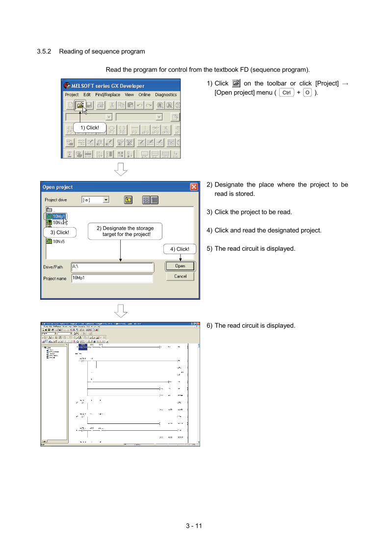
3.5.2 Reading of sequence program
Read the program for control from the textbook FD (sequence program).
1) Click on the toolbar or click [Project] [Open project] menu ( Ctrl + O ).
2) Designate the place where the project to be read is stored.
3) Click the project to be read. 4) Click and read the designated project. 5) The read circuit is displayed.
1) Click!
3) Click!
4) Click!
2) Designate the storage target for the project!
6) The read circuit is displayed.
3 - 12
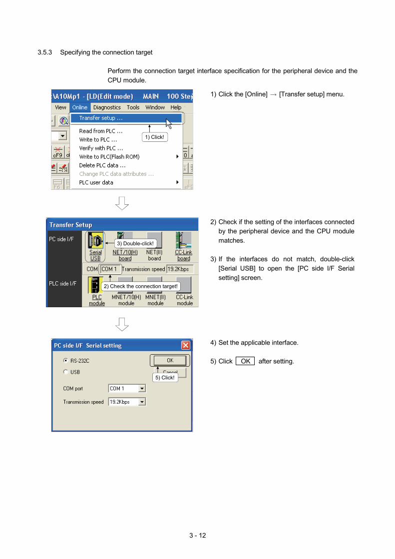
3.5.3 Specifying the connection target
Perform the connection target interface specification for the peripheral device and the CPU module.
1) Click the [Online] [Transfer setup] menu.
2) Check if the setting of the interfaces connected by the peripheral device and the CPU module matches.
3) If the interfaces do not match, double-click
[Serial USB] to open the [PC side I/F Serial setting] screen.
1) Click!
3) Double-click!
2) Check the connection target!
5) Click!
4) Set the applicable interface. 5) Click OK after setting.
3 - 13
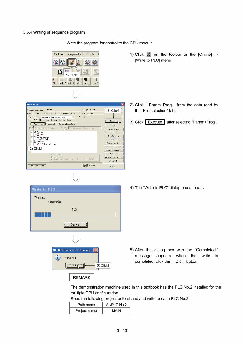
3.5.4 Writing of sequence program
Write the program for control to the CPU module.
1) Click on the toolbar or the [Online] [Write to PLC] menu.
2) Click Param+Prog from the data read by the "File selection" tab.
3) Click Execute after selecting "Param+Prog".
4) The "Write to PLC" dialog box appears.
1) Click!
3) Click!
2) Click!
5) Click!
5) After the dialog box with the "Completed." message appears when the write is completed, click the OK button.
REMARK
The demonstration machine used in this textbook has the PLC No.2 installed for the multiple CPU configuration. Read the following project beforehand and write to each PLC No.2.
Path name A: PLC No.2 Project name MAIN
3 - 14
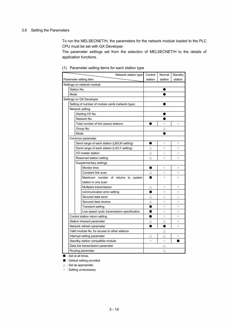
3.6 Setting the Parameters
To run the MELSECNET/H, the parameters for the network module loaded to the PLC CPU must be set with GX Developer. The parameter settings set from the selection of MELSECNET/H to the details of application functions.
(1) Parameter setting items for each station type
Network station type
Parameter setting item Control station
Normal station
Standby station
Settings on network module Station No. Mode Settings on GX Developer Setting of number of module cards (network type) Network setting Starting I/O No. Network No. Total number of link (slave) stations Group No. Mode Common parameter Send range of each station (LB/LW setting) Send range of each station (LX/LY setting) I/O master station Reserved station setting Supplementary settings Monitor time Constant link scan Maximum number of returns to system
station in one scan
Multiplex transmission communication error setting Secured data send Secured data receive Transient setting Low speed cyclic transmission specification Control station return setting Station inherent parameter Network refresh parameter Valid module No. for access to other stations Interrupt setting parameter Standby station compatible module Data link transmission parameter Routing parameter
: Set at all times. : Default setting provided. : Set as appropriate. : Setting unnecessary.
3 - 15
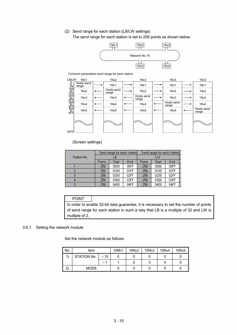
(2) Send range for each station (LB/LW settings)
The send range for each station is set to 256 points as shown below.
Hosts sendrange
1MP1
Common parameters send range for each station
0FF
1001FF2002FF3003FF4004FF
1FFF
LB/LW
1MP1
Network No.10
1NS2 1NS3 1NS4 1NS5
1NS2
1NS3
1NS4
1NS5
1MP1
1NS3
1NS4
1NS5
1MP1
1NS2
1NS4
1NS5
1MP1
1NS2
1NS5
1NS3
1MP1
1NS2
1NS3
1NS4
1NS2 1NS3
1NS41NS5
to
to
to
to
to
Hosts sendrange
Hosts sendrange
Hosts sendrange
Hosts sendrange
(Screen settings)
POINT
In order to enable 32-bit data guarantee, it is necessary to set the number of points of send range for each station in such a way that LB is a multiple of 32 and LW is multiple of 2.
3.6.1 Setting the network module
Set the network module as follows.
No. Item 10MP1 10NS2 10NS3 10NS4 10NS5
10 0 0 0 0 0 1) STATION No. 1 1 2 3 4 5
2) MODE 0 0 0 0 0
3 - 16
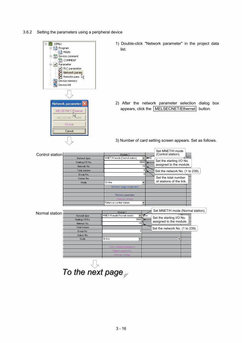
3.6.2 Setting the parameters using a peripheral device
1) Double-click "Network parameter" in the project data list.
2) After the network parameter selection dialog boxappears, click the MELSECNET/Ethernet button.
3) Number of card setting screen appears. Set as follows.
To the next pageTo the next pageTo the next page
Control station
Set the network No. (1 to 239).
Set the starting I/O No. assigned to the module.
Normal stationSet MNET/H mode (Normal station).
Set MNET/H mode (Control station).
Set the total number of stations of the link.
Set the starting I/O No. assigned to the module.
Set the network No. (1 to 239).
3 - 17
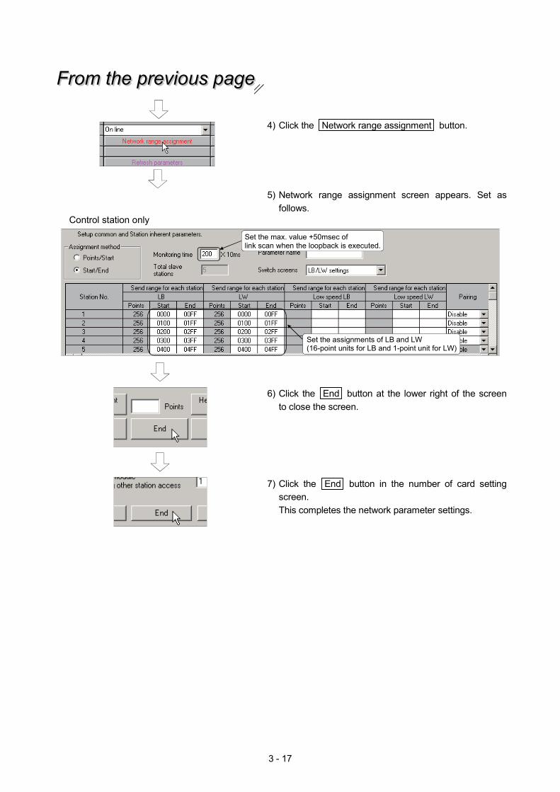
4) Click the Network range assignment button.
From the previous pageFrom the previous pageFrom the previous page
5) Network range assignment screen appears. Set as follows.
Control station only
Set the max. value +50msec of link scan when the loopback is executed.
Set the assignments of LB and LW (16-point units for LB and 1-point unit for LW)
6) Click the End button at the lower right of the screen to close the screen.
7) Click the End button in the number of card setting screen. This completes the network parameter settings.
3 - 18
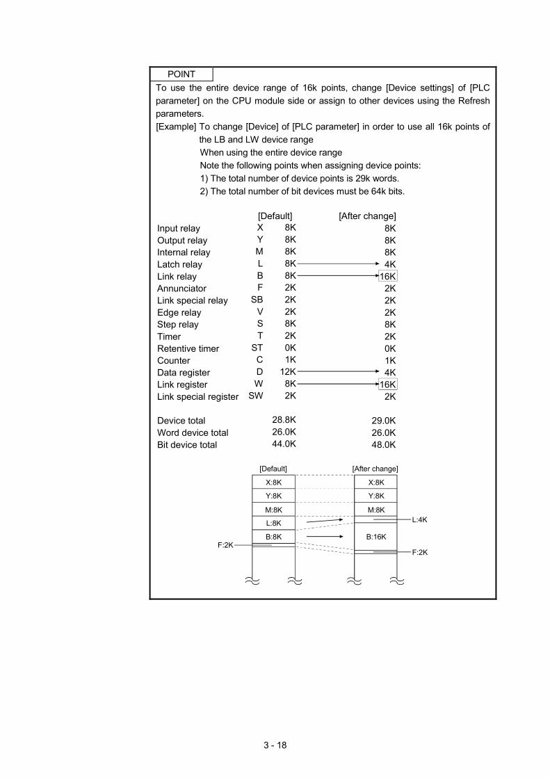
POINT
To use the entire device range of 16k points, change [Device settings] of [PLC parameter] on the CPU module side or assign to other devices using the Refresh parameters. [Example] To change [Device] of [PLC parameter] in order to use all 16k points of
the LB and LW device range When using the entire device range Note the following points when assigning device points: 1) The total number of device points is 29k words. 2) The total number of bit devices must be 64k bits.
Input relayOutput relayInternal relayLatch relayLink relayAnnunciatorLink special relayEdge relayStep relayTimerRetentive timerCounterData registerLink registerLink special register
Device totalWord device totalBit device total
8K8K8K8K8K2K2K2K8K2K0K1K
12K8K2K
28.8K26.0K44.0K
XYMLBF
SBVST
STCDW
SW
8K8K8K4K
16K2K2K2K8K2K0K1K4K
16K2K
29.0K26.0K48.0K
[Default] [After change]
X:8K
[Default]
Y:8K
M:8K
L:8K
B:8KF:2K
[After change]
X:8K
Y:8K
M:8K
B:16K
L:4K
F:2K
3 - 19
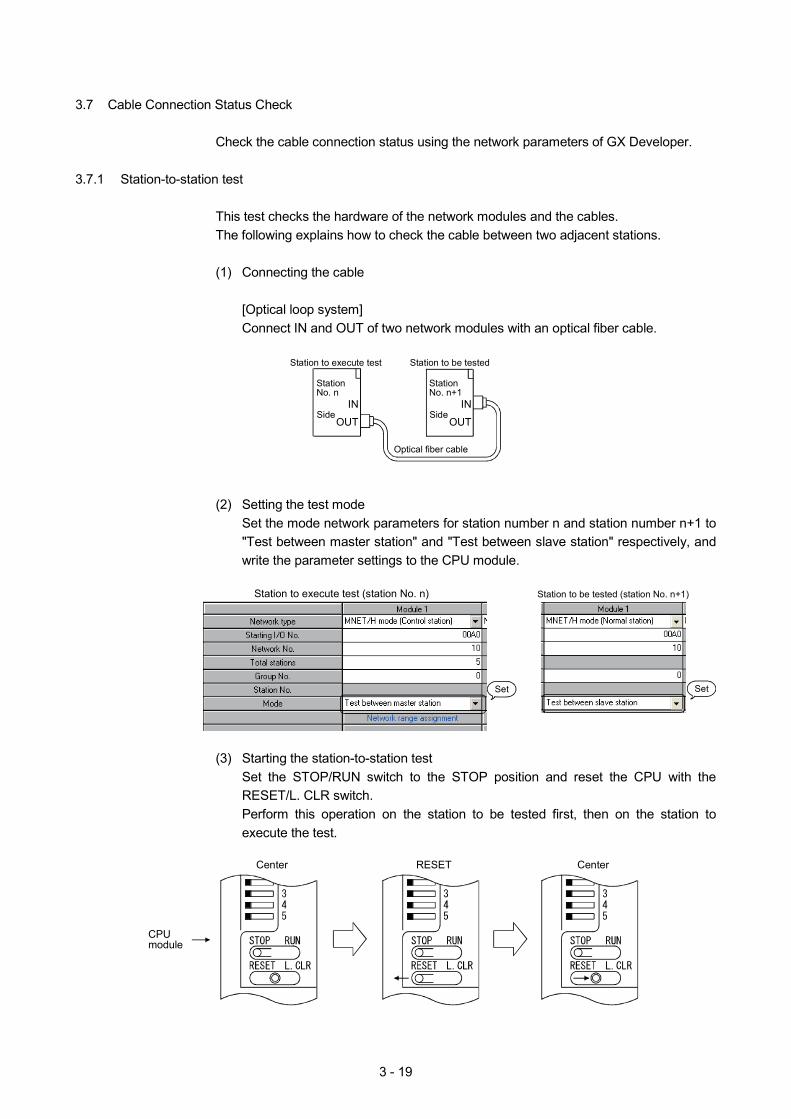
3.7 Cable Connection Status Check
Check the cable connection status using the network parameters of GX Developer. 3.7.1 Station-to-station test
This test checks the hardware of the network modules and the cables. The following explains how to check the cable between two adjacent stations.
(1) Connecting the cable
[Optical loop system] Connect IN and OUT of two network modules with an optical fiber cable.
Side
Station No. n
Optical fiber cable
Station to execute test Station to be tested
IN
OUT
IN
OUTSide
Station No. n+1
(2) Setting the test mode Set the mode network parameters for station number n and station number n+1 to "Test between master station" and "Test between slave station" respectively, and write the parameter settings to the CPU module.
Station to execute test (station No. n) Station to be tested (station No. n+1)
SetSet
(3) Starting the station-to-station test
Set the STOP/RUN switch to the STOP position and reset the CPU with the RESET/L. CLR switch. Perform this operation on the station to be tested first, then on the station to execute the test.
Center RESET
CPU module
Center
3 - 20
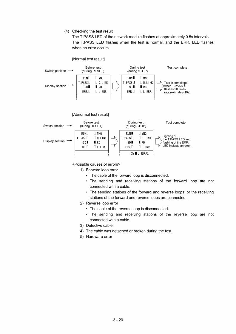
(4) Checking the test result
The T.PASS LED of the network module flashes at approximately 0.5s intervals. The T.PASS LED flashes when the test is normal, and the ERR. LED flashes when an error occurs.
[Normal test result]
Switch position
Display section
Before test(during RESET)
Test complete
Test is completedwhen T.PASSflashes 20 times(approximately 10s).
During test(during STOP)
[Abnormal test result]
Or L. ERR. L
Switch position
Display section
Before test(during RESET)
During test(during STOP)
Test complete
Lighting of the T.PASS LED and flashing of the ERR. LED indicate an error.
<Possible causes of errors>
1) Forward loop error • The cable of the forward loop is disconnected. • The sending and receiving stations of the forward loop are not
connected with a cable. • The sending stations of the forward and reverse loops, or the receiving
stations of the forward and reverse loops are connected. 2) Reverse loop error
• The cable of the reverse loop is disconnected. • The sending and receiving stations of the reverse loop are not
connected with a cable. 3) Defective cable 4) The cable was detached or broken during the test. 5) Hardware error
3 - 21
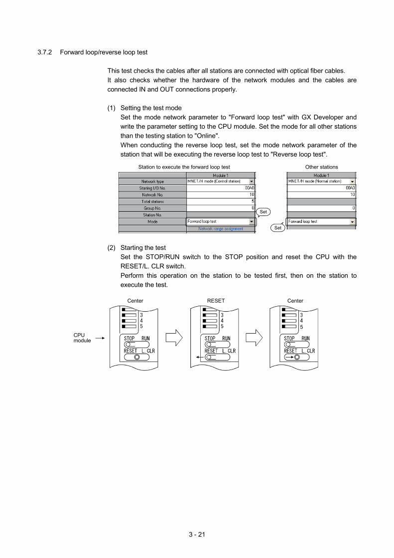
3.7.2 Forward loop/reverse loop test
This test checks the cables after all stations are connected with optical fiber cables. It also checks whether the hardware of the network modules and the cables are connected IN and OUT connections properly.
(1) Setting the test mode
Set the mode network parameter to "Forward loop test" with GX Developer and write the parameter setting to the CPU module. Set the mode for all other stations than the testing station to "Online". When conducting the reverse loop test, set the mode network parameter of the station that will be executing the reverse loop test to "Reverse loop test".
Station to execute the forward loop test Other stations
Set
Set
(2) Starting the test
Set the STOP/RUN switch to the STOP position and reset the CPU with the RESET/L. CLR switch. Perform this operation on the station to be tested first, then on the station to execute the test.
5
Center RESET
CPU module
Center
3 - 22
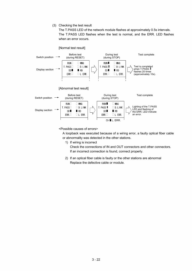
(3) Checking the test result
The T.PASS LED of the network module flashes at approximately 0.5s intervals. The T.PASS LED flashes when the test is normal, and the ERR. LED flashes when an error occurs.
[Normal test result]
Test complete
Switch position
Display section
Before test(during RESET)
Test is completedwhen T.PASSflashes 20 times(approximately 10s).
During test(during STOP)
[Abnormal test result]
Switch position
Display section
Before test(during RESET)
Test complete
Lighting of the T.PASS LED and flashing of the ERR. LED indicate an error.
Or L. ERR. L
During test(during STOP)
<Possible causes of errors>
A loopback was executed because of a wiring error, a faulty optical fiber cable or abnormality was detected in the other stations.
1) If wiring is incorrect Check the connections of IN and OUT connectors and other connectors. If an incorrect connection is found, connect properly.
2) If an optical fiber cable is faulty or the other stations are abnormal
Replace the defective cable or module.
3 - 23
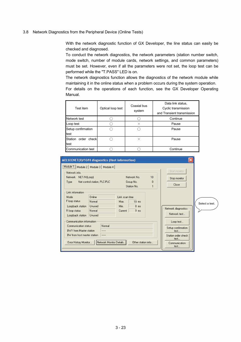
3.8 Network Diagnostics from the Peripheral Device (Online Tests)
With the network diagnostic function of GX Developer, the line status can easily be checked and diagnosed. To conduct the network diagnostics, the network parameters (station number switch, mode switch, number of module cards, network settings, and common parameters) must be set. However, even if all the parameters were not set, the loop test can be performed while the "T.PASS" LED is on. The network diagnostics function allows the diagnostics of the network module while maintaining it in the online status when a problem occurs during the system operation. For details on the operations of each function, see the GX Developer Operating Manual.
Test item Optical loop test Coaxial bus
system
Data link status, Cyclic transmission
and Transient transmission
Network test Continue Loop test Pause Setup confirmation test
Pause
Station order check test
Pause
Communication test Continue
Select a test.
3 - 24
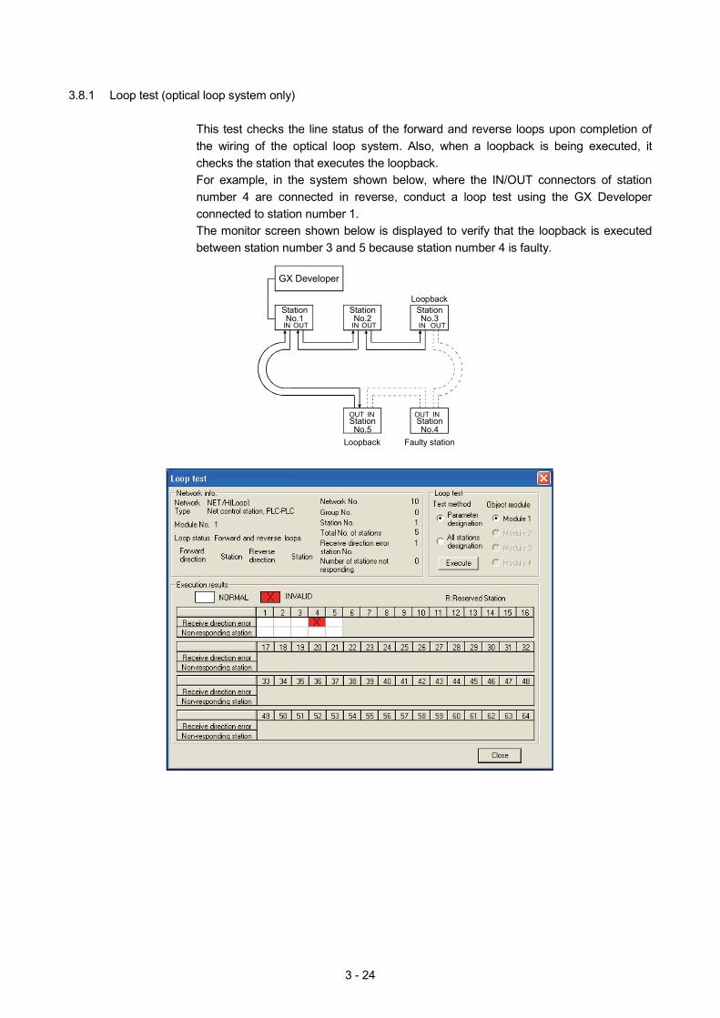
3.8.1 Loop test (optical loop system only)
This test checks the line status of the forward and reverse loops upon completion of the wiring of the optical loop system. Also, when a loopback is being executed, it checks the station that executes the loopback. For example, in the system shown below, where the IN/OUT connectors of station number 4 are connected in reverse, conduct a loop test using the GX Developer connected to station number 1. The monitor screen shown below is displayed to verify that the loopback is executed between station number 3 and 5 because station number 4 is faulty.
GX Developer
StationNo.1
Loopback
IN OUT IN OUTIN OUT
INOUT INOUT
Loopback Faulty station
StationNo.2
StationNo.3
StationNo.4
StationNo.5
3 - 25
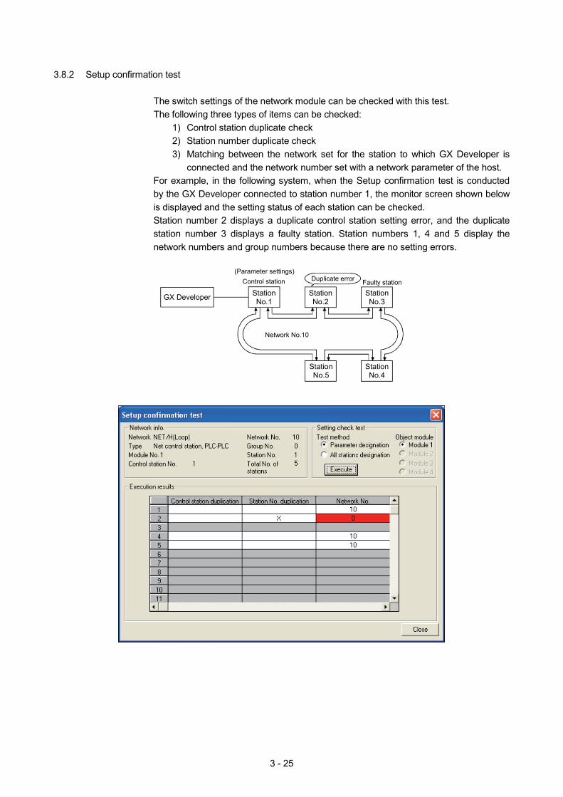
3.8.2 Setup confirmation test
The switch settings of the network module can be checked with this test. The following three types of items can be checked:
1) Control station duplicate check 2) Station number duplicate check 3) Matching between the network set for the station to which GX Developer is
connected and the network number set with a network parameter of the host. For example, in the following system, when the Setup confirmation test is conducted by the GX Developer connected to station number 1, the monitor screen shown below is displayed and the setting status of each station can be checked. Station number 2 displays a duplicate control station setting error, and the duplicate station number 3 displays a faulty station. Station numbers 1, 4 and 5 display the network numbers and group numbers because there are no setting errors.
StationNo.1
(Parameter settings)Control station
Network No.10
Duplicate error Faulty station
GX Developer StationNo.2
StationNo.3
StationNo.4
StationNo.5
3 - 26
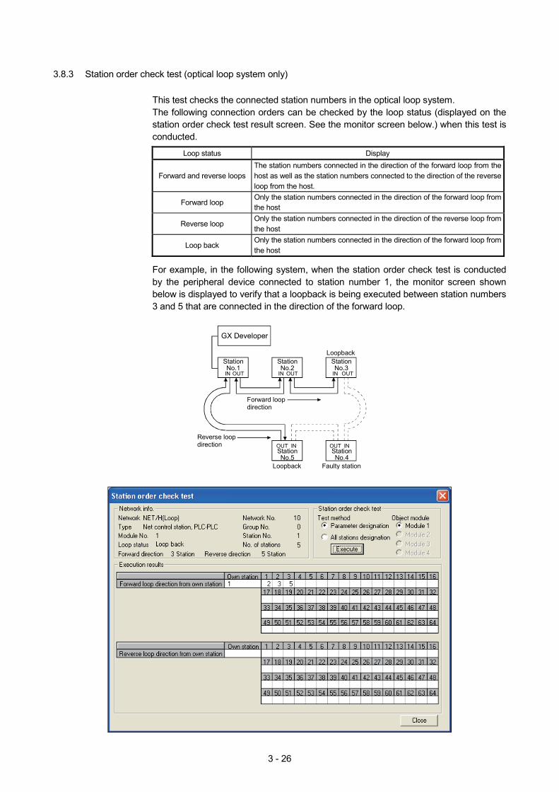
3.8.3 Station order check test (optical loop system only)
This test checks the connected station numbers in the optical loop system. The following connection orders can be checked by the loop status (displayed on the station order check test result screen. See the monitor screen below.) when this test is conducted.
Loop status Display
Forward and reverse loops The station numbers connected in the direction of the forward loop from the host as well as the station numbers connected to the direction of the reverse loop from the host.
Forward loop Only the station numbers connected in the direction of the forward loop from the host
Reverse loop Only the station numbers connected in the direction of the reverse loop from the host
Loop back Only the station numbers connected in the direction of the forward loop from the host
For example, in the following system, when the station order check test is conducted by the peripheral device connected to station number 1, the monitor screen shown below is displayed to verify that a loopback is being executed between station numbers 3 and 5 that are connected in the direction of the forward loop.
Forward loop direction
IN OUT IN OUT
GX Developer
IN OUT
INOUT INOUTReverse loop direction
StationNo.1
StationNo.2
StationNo.3
StationNo.4
StationNo.5
Loopback
Loopback Faulty station
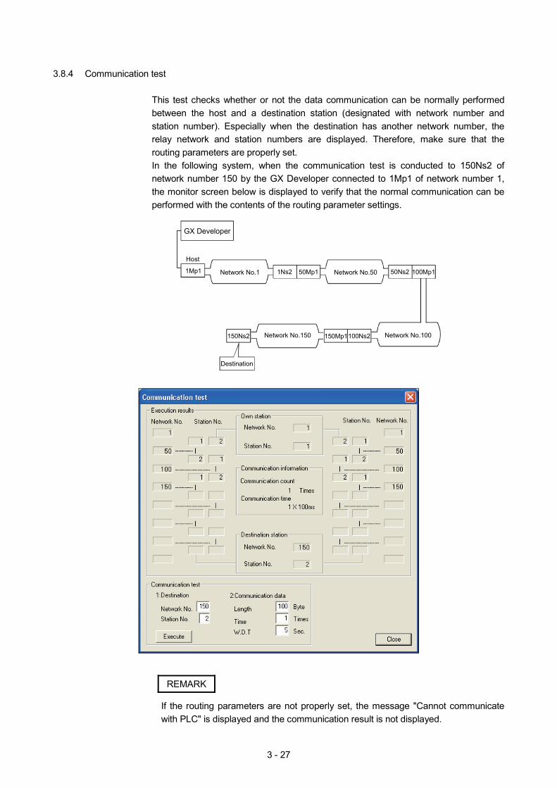
3 - 27
3.8.4 Communication test
This test checks whether or not the data communication can be normally performed between the host and a destination station (designated with network number and station number). Especially when the destination has another network number, the relay network and station numbers are displayed. Therefore, make sure that the routing parameters are properly set. In the following system, when the communication test is conducted to 150Ns2 of network number 150 by the GX Developer connected to 1Mp1 of network number 1, the monitor screen below is displayed to verify that the normal communication can be performed with the contents of the routing parameter settings.
Host
1Mp1 Network No.1 1Ns2 50Mp1
Destination
GX Developer
50Ns2 100Mp1
100Ns2150Mp1150Ns2
Network No.50
Network No.100Network No.150
REMARK
If the routing parameters are not properly set, the message "Cannot communicate with PLC" is displayed and the communication result is not displayed.

3 - 28
3.9 Sequence Program
The following shows the program of 10MP1. When turning X2 ON, Y71 of the host station lights and Y71 from 10Ns2 to 10Ns5 flash. When turning X3 ON, 10 second timer starts measuring and is displayed on Y40 to Y47 of 10Ns2 to 10Ns5.
Path name A: Assignment I
Project name 10Mp1
Host status
SB20: Network module status0
SB20
Host send data Timer measurement
Other station receive data
X2
SW74.1 B100 SM41128
N0 M0
SW74.0
4)
5)4)
9)
37
13)
46
17)
55
64
65
8)
12)
16)
20)
5 B0
Y713)
2)
M0N0MC
T0K99
Y72
Y73
Y74
Y75
T0RST
W0T0MOV
K2Y40W0BCD
K2Y48W100BCD
K2Y50W200BCD
K2Y58W300BCD
K2Y60W400BCD
N0MCR
END
21)
SB47 SB49
X3
T0
1)
SB47: Baton pass statusSB49: Data link status
6) 7)
SW74.2 B200 SM41110) 11)
SW74.3 B300 SM41114) 15)
SW74.4 B400 SM41118) 19)
Timer reset with time-out
Transmits T0 data to W0
Flashes during data receive from 10Ns2
Displays W100 data to 7 segment LED
Flashes during data receive from 10Ns3
Displays W200 data to 7 segment LED
Flashes during data receive from 10Ns4
Displays W300 data to 7 segment LED
Flashes during data receive from 10Ns5
Displays W400 data to 7 segment LED
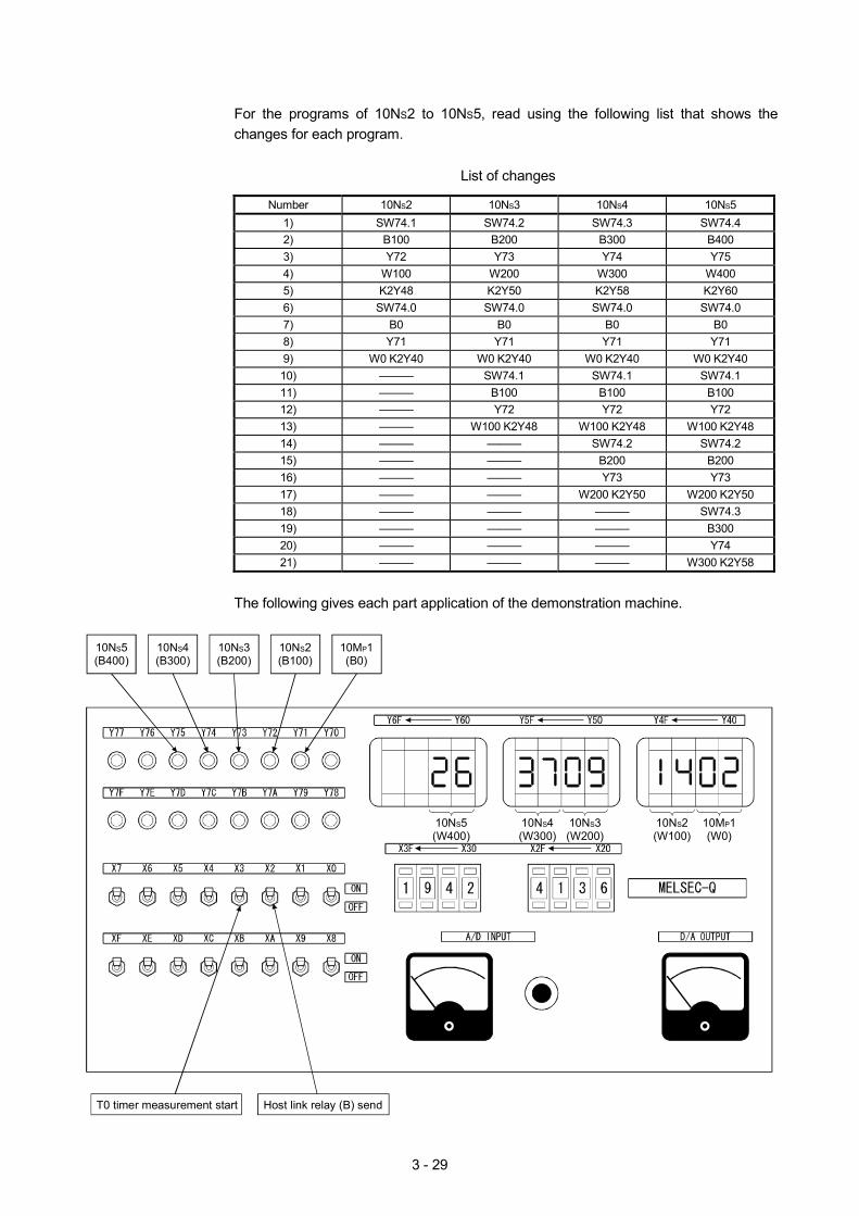
3 - 29
For the programs of 10NS2 to 10NS5, read using the following list that shows the changes for each program.
List of changes
Number 10NS2 10NS3 10NS4 10NS5
1) SW74.1 SW74.2 SW74.3 SW74.4 2) B100 B200 B300 B400 3) Y72 Y73 Y74 Y75 4) W100 W200 W300 W400 5) K2Y48 K2Y50 K2Y58 K2Y60 6) SW74.0 SW74.0 SW74.0 SW74.0 7) B0 B0 B0 B0 8) Y71 Y71 Y71 Y71 9) W0 K2Y40 W0 K2Y40 W0 K2Y40 W0 K2Y40 10) ——— SW74.1 SW74.1 SW74.1 11) ——— B100 B100 B100 12) ——— Y72 Y72 Y72 13) ——— W100 K2Y48 W100 K2Y48 W100 K2Y48 14) ——— ——— SW74.2 SW74.2 15) ——— ——— B200 B200 16) ——— ——— Y73 Y73 17) ——— ——— W200 K2Y50 W200 K2Y50 18) ——— ——— ——— SW74.3 19) ——— ——— ——— B300 20) ——— ——— ——— Y74 21) ——— ——— ——— W300 K2Y58
The following gives each part application of the demonstration machine.
Host link relay (B) sendT0 timer measurement start
10NS5(W400)
10NS5(B400)
10NS4(B300)
10NS3(B200)
10NS2(B100)
10MP1(B0)
10NS4(W300)
10NS3(W200)
10NS2(W100)
10MP1(W0)

3 - 30
MEMO

4 - 1
4
CHAPTER 4 ASSIGNMENT II (TRANSIENT TRANSMISSION)
The configuration of the exercise system is the same as that of Assignment I. 4.1 Transient Transmission Function
The transient transmission function performs data communication only when it is requested between stations. The transient transmission function can be requested by GX Developer, the intelligent function module, the dedicated link instructions (SEND, RECV, READ, WRITE, REQ, ZNRD, ZNWR and RECV), etc. In the MELSECNET/H, data communication can be performed with other stations having the same network number (the same network as the host is connected), as well as with the stations having other network numbers.
4.1.1 Types and descriptions of dedicated link instructions
The following table outlines the instructions that can be used for the MELSECNET/H. For details on the format and program examples of each instruction, see the applicable section listed in the Reference section column.
Dedicated Link Instruction List : Can be used by both the control and normal stations : Cannot be used
Executing station
Target station Instruction Name
QCPU Description
QCPU QnACPU AnUCPU
SEND Send data
RECV Receive data
SEND: Writes data to the target station (network module) having the target network number.
RECV: Reads the data sent with SEND to the CPU device.
CPUNetworkmodule
Channel 1
SEND RECV
Logical channel 1 (Channel 1)
Networkmodule
Channel 2Channel 3Channel 4Channel 5Channel 6Channel 7Channel 8
Logical channel 2 (Channel 2)Logical channel 3 (Channel 3)Logical channel 4 (Channel 4)Logical channel 5 (Channel 5)Logical channel 6 (Channel 6)Logical channel 7 (Channel 7)Logical channel 8 (Channel 8)
CPU
READ SREAD
Read word device from other station
Reads the CPU device data (16-bit units) from the target station having the target network number.
2594
READ
Word device
CPUNetworkmodule
Networkmodule CPU
2594
Word deviceChannel 1Channel 2Channel 3Channel 4Channel 5Channel 6Channel 7Channel 8
WRITE SWRITE
Write word device to other station
Writes data (16-bit units) to the CPU device of the target station having the target network number.
(SWRITE can turn on the device of the target station.)
WRITE 361
CPUNetworkmodule
Networkmodule CPU
Word deviceChannel 1Channel 2Channel 3Channel 4Channel 5Channel 6Channel 7Channel 8
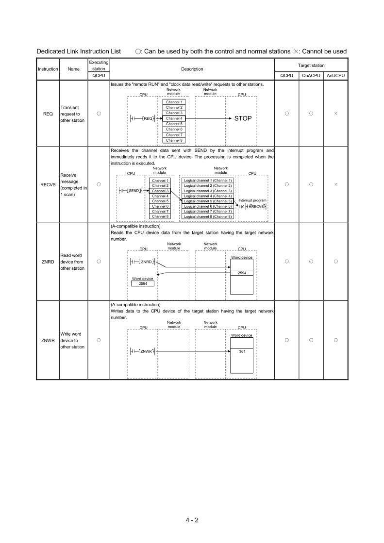
4 - 2
Dedicated Link Instruction List : Can be used by both the control and normal stations : Cannot be used
Executing station
Target station Instruction Name
QCPU Description
QCPU QnACPU AnUCPU
REQ Transient request to other station
Issues the "remote RUN" and "clock data read/write" requests to other stations.
CPUNetworkmodule
STOPREQ
CPUNetworkmodule
Channel 1Channel 2Channel 3Channel 4Channel 5Channel 6Channel 7Channel 8
RECVS
Receive message (completed in 1 scan)
Receives the channel data sent with SEND by the interrupt program and immediately reads it to the CPU device. The processing is completed when the instruction is executed.
SEND
RECVSI10
Interrupt program
CPUNetworkmodule
Networkmodule CPU
Channel 1Channel 2Channel 3Channel 4Channel 5Channel 6Channel 7Channel 8
Logical channel 1 (Channel 1)Logical channel 2 (Channel 2)Logical channel 3 (Channel 3)Logical channel 4 (Channel 4)Logical channel 5 (Channel 5)Logical channel 6 (Channel 6)Logical channel 7 (Channel 7)Logical channel 8 (Channel 8)
ZNRD Read word device from other station
(A-compatible instruction) Reads the CPU device data from the target station having the target network number.
CPUNetworkmodule
Word device
2594
ZNRD
CPU
2594Word device
Networkmodule
ZNWR Write word device to other station
(A-compatible instruction) Writes data to the CPU device of the target station having the target network number.
361ZNWR
CPUNetworkmodule CPU
Networkmodule
Word device
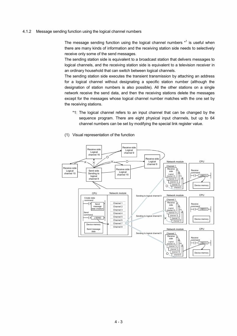
4 - 3
4.1.2 Message sending function using the logical channel numbers
The message sending function using the logical channel numbers *1 is useful when there are many kinds of information and the receiving station side needs to selectively receive only some of the send messages. The sending station side is equivalent to a broadcast station that delivers messages to logical channels, and the receiving station side is equivalent to a television receiver in an ordinary household that can switch between logical channels. The sending station side executes the transient transmission by attaching an address for a logical channel without designating a specific station number (although the designation of station numbers is also possible). All the other stations on a single network receive the send data, and then the receiving stations delete the messages except for the messages whose logical channel number matches with the one set by the receiving stations.
*1: The logical channel refers to an input channel that can be changed by the
sequence program. There are eight physical input channels, but up to 64 channel numbers can be set by modifying the special link register value.
(1) Visual representation of the function
CPUNetwork module
Send sideSending to
logicalchannel 9
Receive sideLogical
channel 16
Create data command
Sendmessage
data creation
J.SEND
Sendcommand
Device memory
Send messagedata
CPU Network module
8
3
Channel 1
2Receiveside
Logicalchannel 15
Channel 1
J.RECV
Receivecommand
Device memory
8
32
8
32
Sending to logical channel 9
Receive sideLogical
channel 10
Receive sideLogical
channel 15
Receive sideLogical
channel 9
Receive sideLogical
channel 9
Channel 2Channel 3
Channel 4
Channel 5Channel 6Channel 7
Channel 8
Sending to logical channel 9
Sending to logical channel 9
CPUNetwork module
CPUNetwork module
channel 14
channel 12
channel 10
channel 9
Receiveside
Channel 1
Logicalchannel 15
channel 14
channel 12
channel 10
channel 13
J.RECV
Receivecommand
Device memory
J.RECV
Receivecommand
Device memory
Channel 1Receive
sideLogical
channel 15channel 14
channel 12
channel 16
channel 9
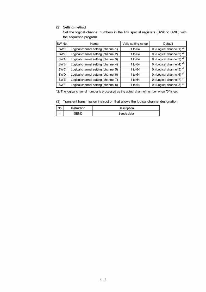
4 - 4
(2) Setting method
Set the logical channel numbers in the link special registers (SW8 to SWF) with the sequence program.
SW No. Name Valid setting range Default
SW8 Logical channel setting (channel 1) 1 to 64 0: (Logical channel 1) *2 SW9 Logical channel setting (channel 2) 1 to 64 0: (Logical channel 2) *2 SWA Logical channel setting (channel 3) 1 to 64 0: (Logical channel 3) *2 SWB Logical channel setting (channel 4) 1 to 64 0: (Logical channel 4) *2 SWC Logical channel setting (channel 5) 1 to 64 0: (Logical channel 5) *2 SWD Logical channel setting (channel 6) 1 to 64 0: (Logical channel 6) *2 SWE Logical channel setting (channel 7) 1 to 64 0: (Logical channel 7) *2 SWF Logical channel setting (channel 8) 1 to 64 0: (Logical channel 8) *2
*2: The logical channel number is processed as the actual channel number when "0" is set.
(3) Transient transmission instruction that allows the logical channel designation
No. Instruction Description
1 SEND Sends data
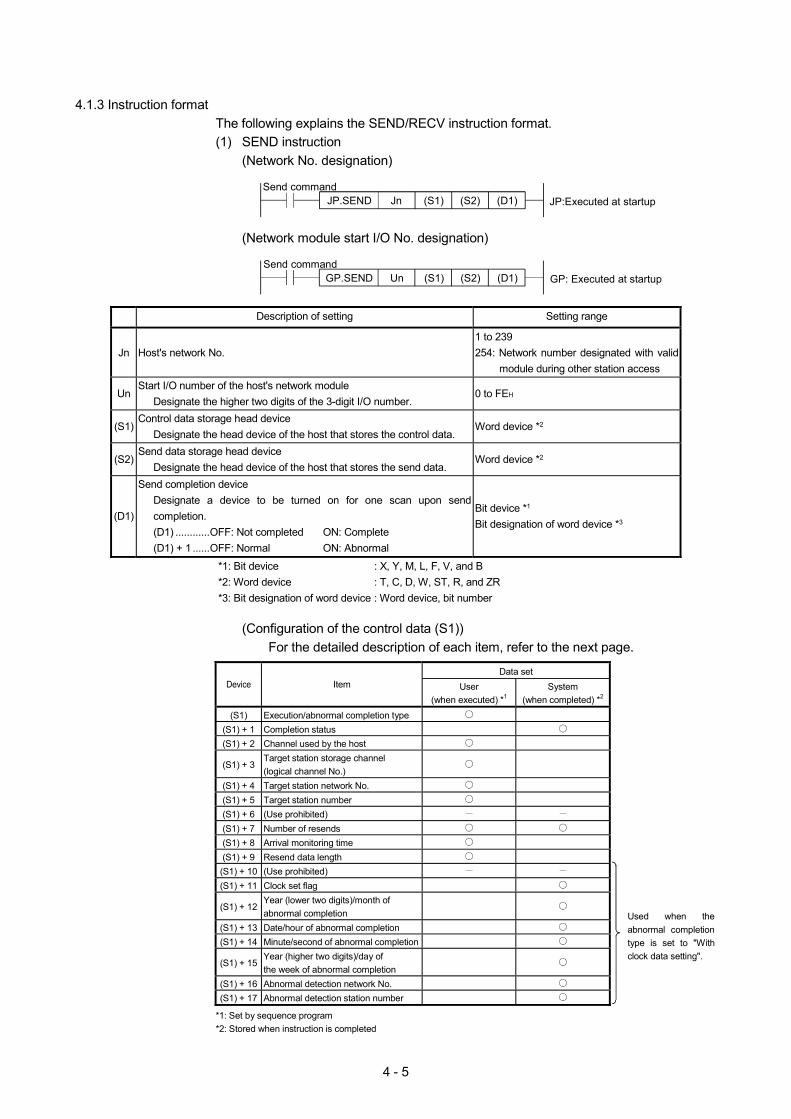
4 - 5
4.1.3 Instruction format
The following explains the SEND/RECV instruction format. (1) SEND instruction
(Network No. designation)
JP.SEND JP:Executed at startupSend command
Jn (S1) (S2) (D1)
(Network module start I/O No. designation)
GP.SEND GP: Executed at startupSend command
Un (S1) (S2) (D1)
Description of setting Setting range
Jn Host's network No. 1 to 239 254: Network number designated with valid
module during other station access
Un Start I/O number of the host's network module
Designate the higher two digits of the 3-digit I/O number. 0 to FEH
(S1) Control data storage head device
Designate the head device of the host that stores the control data. Word device *2
(S2) Send data storage head device
Designate the head device of the host that stores the send data. Word device *2
(D1)
Send completion device Designate a device to be turned on for one scan upon send completion. (D1) ............OFF: Not completed ON: Complete (D1) + 1 ......OFF: Normal ON: Abnormal
Bit device *1
Bit designation of word device *3
*1: Bit device : X, Y, M, L, F, V, and B *2: Word device : T, C, D, W, ST, R, and ZR *3: Bit designation of word device : Word device, bit number
(Configuration of the control data (S1))
For the detailed description of each item, refer to the next page.
Data set Device Item User
(when executed) *1 System
(when completed) *2
(S1) Execution/abnormal completion type (S1) + 1 Completion status (S1) + 2 Channel used by the host
(S1) + 3 Target station storage channel (logical channel No.)
(S1) + 4 Target station network No. (S1) + 5 Target station number (S1) + 6 (Use prohibited) (S1) + 7 Number of resends (S1) + 8 Arrival monitoring time (S1) + 9 Resend data length (S1) + 10 (Use prohibited) (S1) + 11 Clock set flag
(S1) + 12 Year (lower two digits)/month of abnormal completion
(S1) + 13 Date/hour of abnormal completion (S1) + 14 Minute/second of abnormal completion
(S1) + 15 Year (higher two digits)/day of the week of abnormal completion
(S1) + 16 Abnormal detection network No. (S1) + 17 Abnormal detection station number
Used when the abnormal completion type is set to "With clock data setting".
*1: Set by sequence program *2: Stored when instruction is completed

4 - 6
Detailed description of the control data
Device Item Description
(S1) Execution/abnormal completion type
b15 b7 b0
0 2) 1)0to to
1) Execution type (bit 0)
0: No arrival confirmation When the target station is on the local network : Completed when data is sent from the
host.
Executionsource
Targetstation
Complete
When the target station is on the other network : Completed when the data arrives at
the relay station on the network of the local station.
Executionsource
Relaystation
Complete
Targetstation
1: With arrival confirmation
Completed when the data is stored in the target station's designated channel.
Executionsource
Relaystation
Complete
Targetstation
Targetstation
2) Abnormal completion type (bit 7)
Sets the clock data set status at abnormal completion. 0: Does not set the clock data : Does not store the clock data at error
occurrence in (S1) + 11 to (S1) + 17. 1: Sets the clock data : Stores the clock data at error occurrence
in (S1) + 11 to (S1) + 17.
(S1) + 1 Completion status Stores the status when an instruction is completed.
0 : Normal Other than 0 : Abnormal (Refer to Appendix 5 for error codes)
(S1) + 2 Channel used by the host Designates the channel to be used by the host.
1 to 8 (channels)
(S1) + 3 Target station storage channel (logical channel No.)
Designates the target station's channel to store the data. 1 to 64 (logical channel)
(S1) + 4 Target station network No.
Designates the network No. of the target station. 1 to 239 : Network No. 254 : Designates with the parameter setting, "Valid module during other station
access" setting, when 254 is designated in Jn.
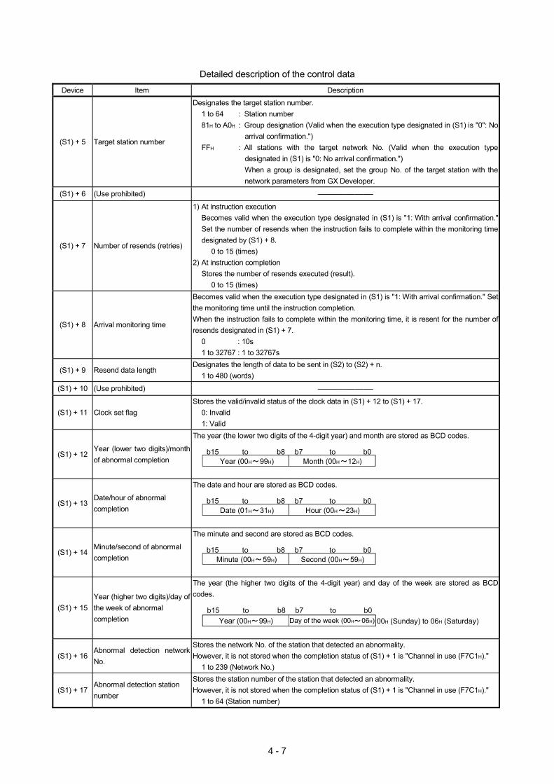
4 - 7
Detailed description of the control data
Device Item Description
(S1) + 5 Target station number
Designates the target station number. 1 to 64 : Station number 81H to A0H : Group designation (Valid when the execution type designated in (S1) is "0": No
arrival confirmation.") FFH : All stations with the target network No. (Valid when the execution type
designated in (S1) is "0: No arrival confirmation.") When a group is designated, set the group No. of the target station with thenetwork parameters from GX Developer.
(S1) + 6 (Use prohibited) ——————
(S1) + 7 Number of resends (retries)
1) At instruction execution Becomes valid when the execution type designated in (S1) is "1: With arrival confirmation." Set the number of resends when the instruction fails to complete within the monitoring time designated by (S1) + 8.
0 to 15 (times) 2) At instruction completion
Stores the number of resends executed (result). 0 to 15 (times)
(S1) + 8 Arrival monitoring time
Becomes valid when the execution type designated in (S1) is "1: With arrival confirmation." Set the monitoring time until the instruction completion. When the instruction fails to complete within the monitoring time, it is resent for the number of resends designated in (S1) + 7.
0 : 10s 1 to 32767 : 1 to 32767s
(S1) + 9 Resend data length Designates the length of data to be sent in (S2) to (S2) + n.
1 to 480 (words)
(S1) + 10 (Use prohibited) ——————
(S1) + 11 Clock set flag Stores the valid/invalid status of the clock data in (S1) + 12 to (S1) + 17.
0: Invalid 1: Valid
(S1) + 12 Year (lower two digits)/month of abnormal completion
The year (the lower two digits of the 4-digit year) and month are stored as BCD codes.
b15 b7 b0b8Year (00H 99H)
to toMonth (00H 12H)
(S1) + 13 Date/hour of abnormal completion
The date and hour are stored as BCD codes.
b15 b7 b0b8Date (01H 31H)
to to Hour (00H 23H)
(S1) + 14 Minute/second of abnormal completion
The minute and second are stored as BCD codes.
b15 b7 b0b8Minute (00H 59H)
to to Second (00H 59H)
(S1) + 15 Year (higher two digits)/day of the week of abnormal completion
The year (the higher two digits of the 4-digit year) and day of the week are stored as BCD codes.
00H (Sunday) to 06H (Saturday)b15 b7 b0b8to to
Year (00H 99H) Day of the week (00H 06H)
(S1) + 16 Abnormal detection network No.
Stores the network No. of the station that detected an abnormality. However, it is not stored when the completion status of (S1) + 1 is "Channel in use (F7C1H)."
1 to 239 (Network No.)
(S1) + 17 Abnormal detection station number
Stores the station number of the station that detected an abnormality. However, it is not stored when the completion status of (S1) + 1 is "Channel in use (F7C1H)."
1 to 64 (Station number)
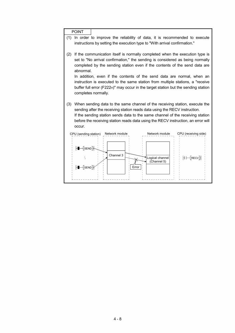
4 - 8
POINT
(1) In order to improve the reliability of data, it is recommended to execute instructions by setting the execution type to "With arrival confirmation."
(2) If the communication itself is normally completed when the execution type is
set to "No arrival confirmation," the sending is considered as being normally completed by the sending station even if the contents of the send data are abnormal. In addition, even if the contents of the send data are normal, when an instruction is executed to the same station from multiple stations, a "receive buffer full error (F222H)" may occur in the target station but the sending station completes normally.
(3) When sending data to the same channel of the receiving station, execute the
sending after the receiving station reads data using the RECV instruction. If the sending station sends data to the same channel of the receiving station before the receiving station reads data using the RECV instruction, an error will occur.
CPU (sending station) Network module CPU (receiving side)
RECV
SEND
Channel 3
Error
Logical channel(Channel 5)
Network module
SEND
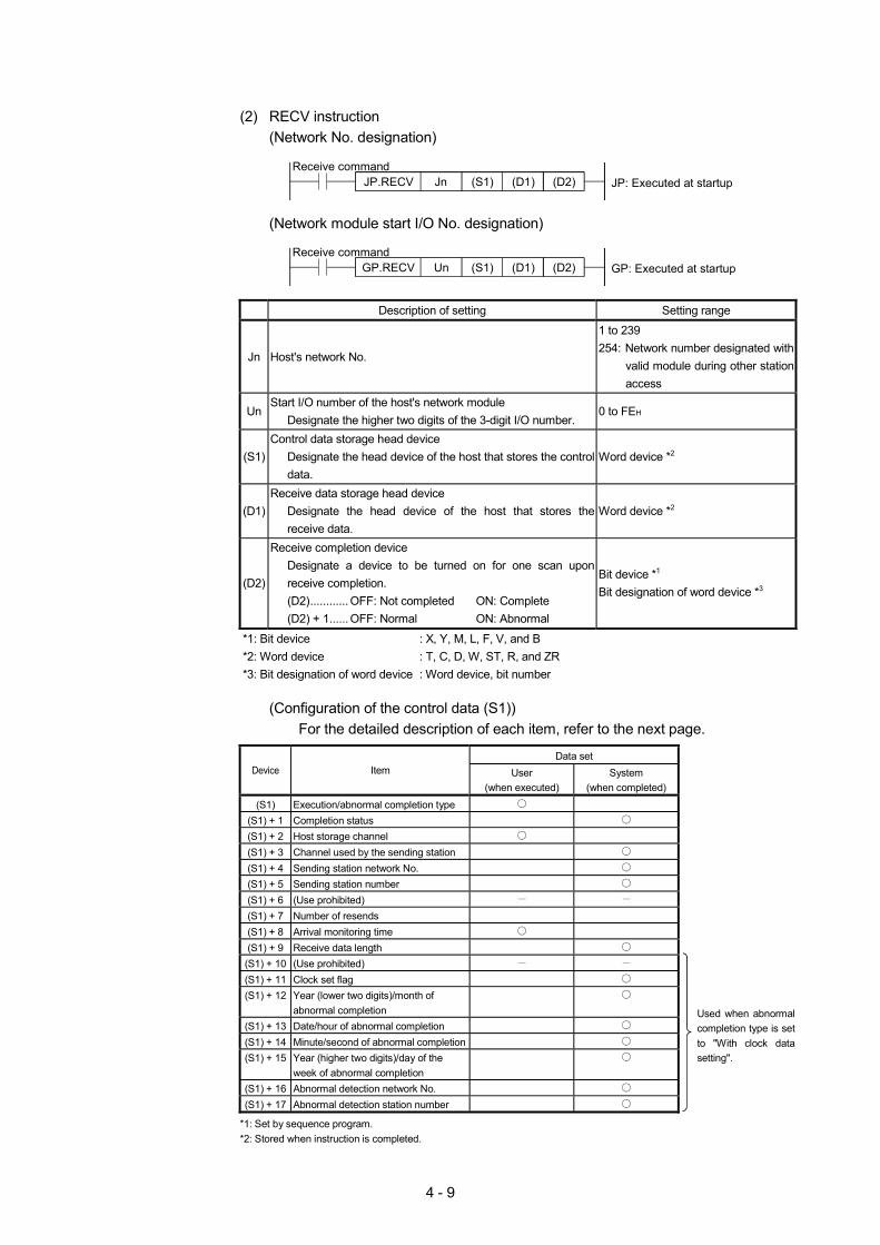
4 - 9
(2) RECV instruction
(Network No. designation)
JP.RECV JP: Executed at startupReceive command
Jn (S1) (D1) (D2)
(Network module start I/O No. designation)
GP.RECV GP: Executed at startupReceive command
Un (S1) (D1) (D2)
Description of setting Setting range
Jn Host's network No.
1 to 239 254: Network number designated with
valid module during other station access
UnStart I/O number of the host's network module
Designate the higher two digits of the 3-digit I/O number. 0 to FEH
(S1)Control data storage head device
Designate the head device of the host that stores the control data.
Word device *2
(D1)Receive data storage head device
Designate the head device of the host that stores the receive data.
Word device *2
(D2)
Receive completion device Designate a device to be turned on for one scan upon receive completion. (D2)............ OFF: Not completed ON: Complete (D2) + 1...... OFF: Normal ON: Abnormal
Bit device *1 Bit designation of word device *3
*1: Bit device : X, Y, M, L, F, V, and B *2: Word device : T, C, D, W, ST, R, and ZR *3: Bit designation of word device : Word device, bit number
(Configuration of the control data (S1))
For the detailed description of each item, refer to the next page.
Data set Device Item User
(when executed) System
(when completed) (S1) Execution/abnormal completion type
(S1) + 1 Completion status (S1) + 2 Host storage channel (S1) + 3 Channel used by the sending station (S1) + 4 Sending station network No. (S1) + 5 Sending station number (S1) + 6 (Use prohibited) (S1) + 7 Number of resends (S1) + 8 Arrival monitoring time (S1) + 9 Receive data length (S1) + 10 (Use prohibited) (S1) + 11 Clock set flag (S1) + 12 Year (lower two digits)/month of
abnormal completion
(S1) + 13 Date/hour of abnormal completion (S1) + 14 Minute/second of abnormal completion (S1) + 15 Year (higher two digits)/day of the
week of abnormal completion
(S1) + 16 Abnormal detection network No. (S1) + 17 Abnormal detection station number
Used when abnormal completion type is set to "With clock data setting".
*1: Set by sequence program. *2: Stored when instruction is completed.
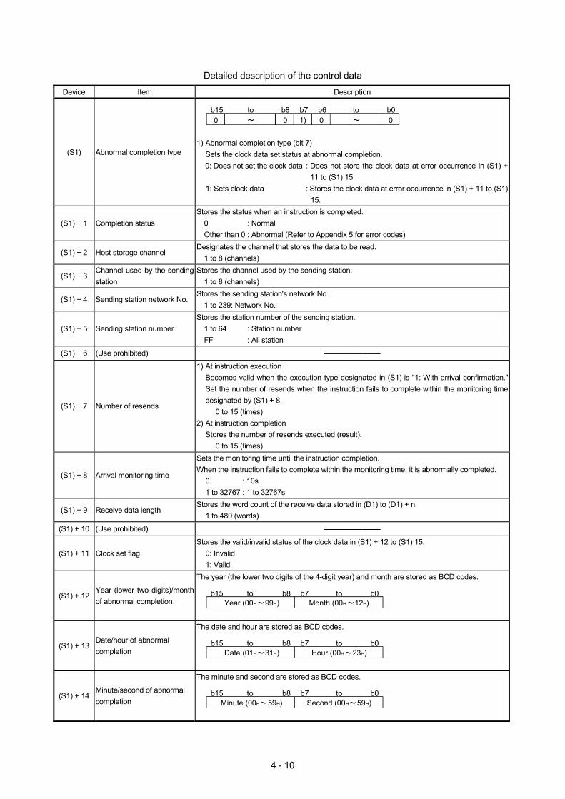
4 - 10
Detailed description of the control data
Device Item Description
(S1) Abnormal completion type
b15 b7 b0
1)b8 b6
0 0 0 0to to
1) Abnormal completion type (bit 7)
Sets the clock data set status at abnormal completion. 0: Does not set the clock data : Does not store the clock data at error occurrence in (S1) +
11 to (S1) 15. 1: Sets clock data : Stores the clock data at error occurrence in (S1) + 11 to (S1)
15.
(S1) + 1 Completion status Stores the status when an instruction is completed.
0 : Normal Other than 0 : Abnormal (Refer to Appendix 5 for error codes)
(S1) + 2 Host storage channel Designates the channel that stores the data to be read.
1 to 8 (channels)
(S1) + 3 Channel used by the sending station
Stores the channel used by the sending station. 1 to 8 (channels)
(S1) + 4 Sending station network No. Stores the sending station's network No.
1 to 239: Network No.
(S1) + 5 Sending station number Stores the station number of the sending station.
1 to 64 : Station number FFH : All station
(S1) + 6 (Use prohibited) ——————
(S1) + 7 Number of resends
1) At instruction execution Becomes valid when the execution type designated in (S1) is "1: With arrival confirmation." Set the number of resends when the instruction fails to complete within the monitoring time designated by (S1) + 8.
0 to 15 (times) 2) At instruction completion
Stores the number of resends executed (result). 0 to 15 (times)
(S1) + 8 Arrival monitoring time
Sets the monitoring time until the instruction completion. When the instruction fails to complete within the monitoring time, it is abnormally completed.
0 : 10s 1 to 32767 : 1 to 32767s
(S1) + 9 Receive data length Stores the word count of the receive data stored in (D1) to (D1) + n.
1 to 480 (words)
(S1) + 10 (Use prohibited) ——————
(S1) + 11 Clock set flag Stores the valid/invalid status of the clock data in (S1) + 12 to (S1) 15.
0: Invalid 1: Valid
(S1) + 12 Year (lower two digits)/month of abnormal completion
The year (the lower two digits of the 4-digit year) and month are stored as BCD codes.
b15 b7 b0b8Year (00H 99H)
to toMonth (00H 12H)
(S1) + 13 Date/hour of abnormal completion
The date and hour are stored as BCD codes.
b15 b7 b0b8Date (01H 31H)
to to Hour (00H 23H)
(S1) + 14 Minute/second of abnormal completion
The minute and second are stored as BCD codes.
b15 b7 b0b8Minute (00H 59H)
to to Second (00H 59H)
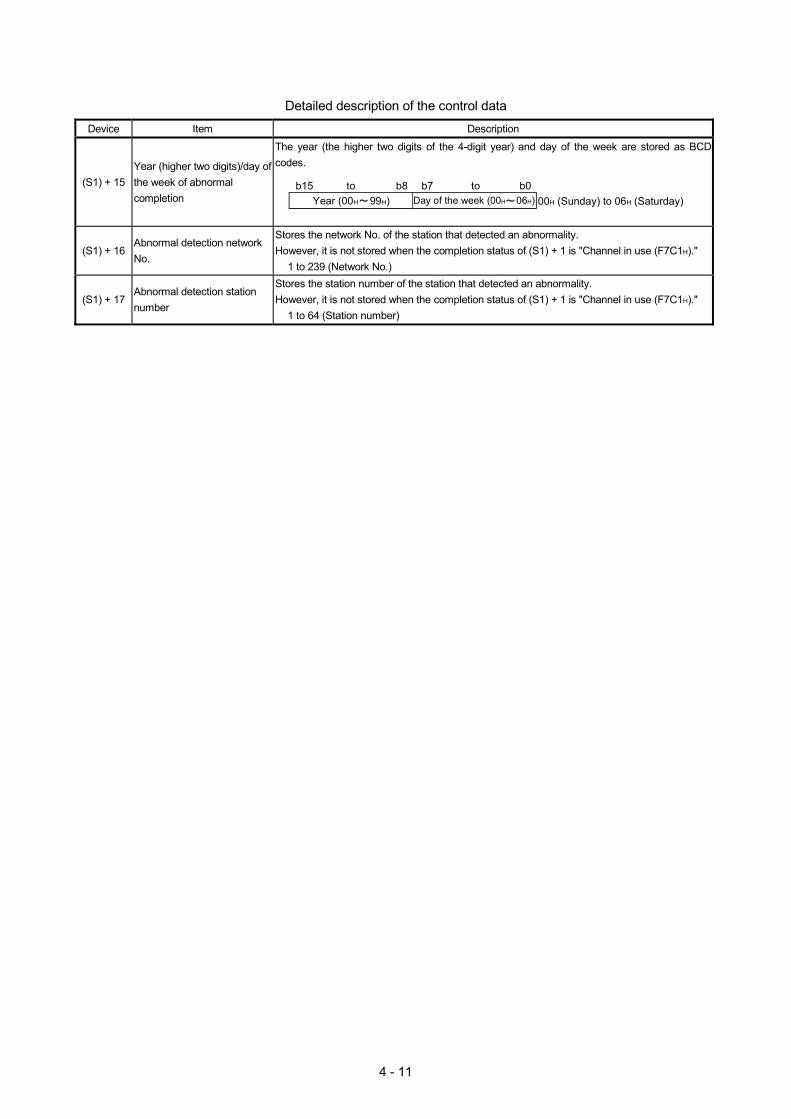
4 - 11
Detailed description of the control data
Device Item Description
(S1) + 15 Year (higher two digits)/day of the week of abnormal completion
The year (the higher two digits of the 4-digit year) and day of the week are stored as BCD codes.
00H (Sunday) to 06H (Saturday)b15 b7 b0b8to to
Year (00H 99H) Day of the week (00H 06H)
(S1) + 16 Abnormal detection network No.
Stores the network No. of the station that detected an abnormality. However, it is not stored when the completion status of (S1) + 1 is "Channel in use (F7C1H)."
1 to 239 (Network No.)
(S1) + 17 Abnormal detection station number
Stores the station number of the station that detected an abnormality. However, it is not stored when the completion status of (S1) + 1 is "Channel in use (F7C1H)."
1 to 64 (Station number)
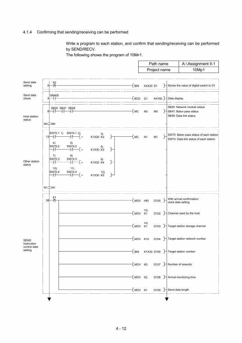
4 - 12
4.1.4 Confirming that sending/receiving can be performed
Write a program to each station, and confirm that sending/receiving can be performed by SEND/RECV. The following shows the program of 10MP1.
Path name A: Assignment II-1
Project name 10Mp1
Stores the value of digital switch to D10X0Send data
setting
Send data check
D1K4X20BIN
Data display4SM400
K4Y60D1BCD
Host station status
SB20: Network module statusSB47: Baton pass statusSB49: Data link status
8SB20
Other station status
SW70: Baton pass status of each stationSW74: Data link status of each station
13SW70.1
M0N0MC
M1N1MCK2K1X30=
K3K1X30=
K4K1X30=
K5K1X30=
1) 2) 3)
6)
9)
12)
4) 5)
7) 8)
10) 11)
SEND instruction control data setting
Number of resends
Arrival monitoring time
Target station number
Target station network number
Target station storage channel
Send data length
With arrival confirmation/clock data setting38
X1
Channel used by the host
N1 M1
N0 M0
D100H81MOV
D102K1MOV
D103K1MOV
D104K10MOV
D105K1X30BIN
D107K5MOV
D108K2MOV
D109K1MOV
13)
14)
SB47 SB49
SW74.1
SW70.2 SW74.2
SW70.3 SW74.3
SW70.4 SW74.4
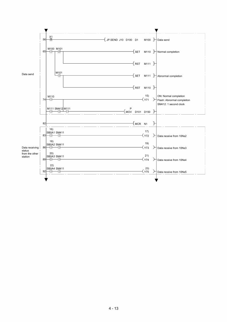
4 - 13
56X1
Data sendAbnormal completion
74
Data receiving status from the other station
M111 M111
SB0A1
92
M110
65M100 M101
SM412
SM411
Data receive from 10Ns5
Data receive from 10Ns4
Data receive from 10Ns3
Data receive from 10Ns2
82
83
86
89
Data send
Normal completion
ON: Normal completionFlash: Abnormal completionSM412: 1 second clock
M100D1D100
M110SET
M111RST
D150D101MOV
N1MCR
J10JP.SEND
M111SET
M110RST
P
Y71
Y72
Y73
Y74
Y75
16)
18)
20)
19)
17)
21)
22)23)
15)
M101
SB0A2 SM411
SB0A3 SM411
SB0A4 SM411
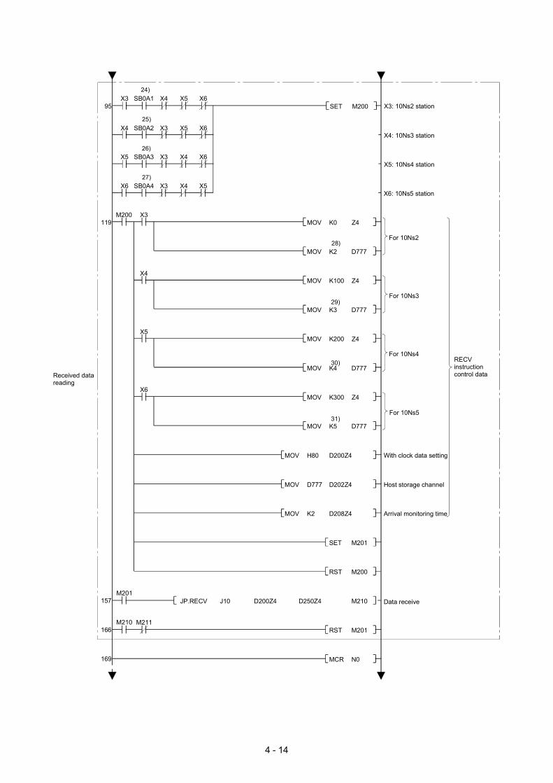
4 - 14
Received data reading
For 10Ns3
119
With clock data setting
169
M210 M211
Data receive157
166
For 10Ns2
X6: 10Ns5 station
For 10Ns4
For 10Ns5
Arrival monitoring time
M200 X3
Host storage channel
RECV instruction control data
X3: 10Ns2 station95X3
X4: 10Ns3 station
SB0A1 X4 X5 X6
X5: 10Ns4 station
Z4K0MOV
M200SET
D777K2MOV
Z4K100MOV
D777K3MOV
Z4K200MOV
D777K4MOV
Z4K300MOV
D777K5MOV
D200Z4H80
M201SET
M200RST
M210D250Z4D200Z4
M201RST
N0MCR
MOV
D202Z4D777MOV
D208Z4K2MOV
J10JP.RECV
25)
26)
27)
28)
29)
30)
31)
24)
M201
X4 SB0A2 X3 X5 X6
X5 SB0A3 X3 X4 X6
X6 SB0A4 X3 X4 X5
X4
X5
X6

4 - 15
170X7
Display of 10Ns4 data
202
Display of 10Ns5 data
Display of station number
Display of 10Ns2 data
Display of 10Ns3 data
K1Y50K1X38BCD
K4Y40D250
END
K2K1X38=
K3K1X38=
K4K1X38=
K5K1X38=
BCD
K4Y40D350BCD
K4Y40D450BCD
K4Y40D550BCD
32)
33)
34)
35)
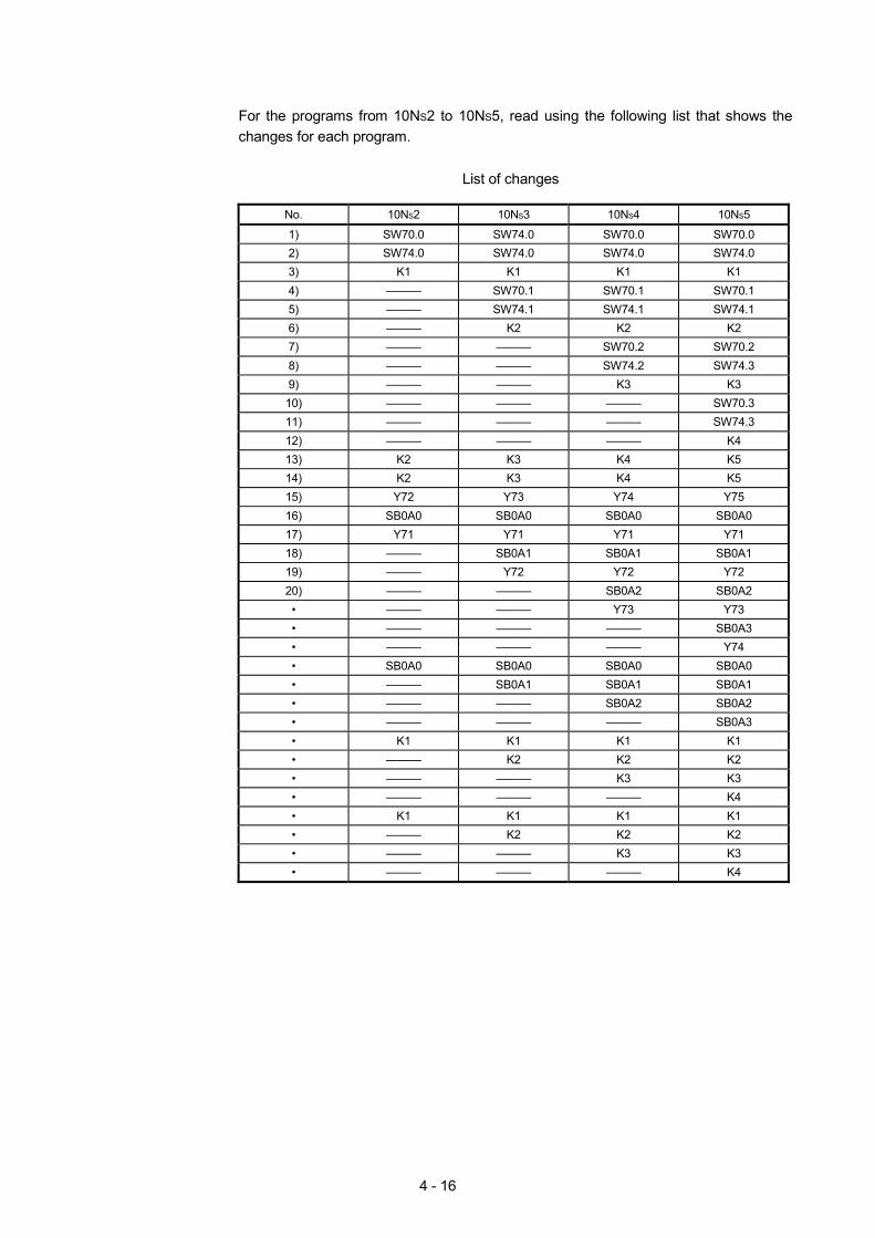
4 - 16
For the programs from 10NS2 to 10NS5, read using the following list that shows the changes for each program.
List of changes
No. 10NS2 10NS3 10NS4 10NS5
1) SW70.0 SW74.0 SW70.0 SW70.0 2) SW74.0 SW74.0 SW74.0 SW74.0 3) K1 K1 K1 K1 4) ——— SW70.1 SW70.1 SW70.1 5) ——— SW74.1 SW74.1 SW74.1 6) ——— K2 K2 K2 7) ——— ——— SW70.2 SW70.2 8) ——— ——— SW74.2 SW74.3 9) ——— ——— K3 K3 10) ——— ——— ——— SW70.3 11) ——— ——— ——— SW74.3 12) ——— ——— ——— K4 13) K2 K3 K4 K5 14) K2 K3 K4 K5 15) Y72 Y73 Y74 Y75 16) SB0A0 SB0A0 SB0A0 SB0A0 17) Y71 Y71 Y71 Y71 18) ——— SB0A1 SB0A1 SB0A1 19) ——— Y72 Y72 Y72 20) ——— ——— SB0A2 SB0A2 • ——— ——— Y73 Y73 • ——— ——— ——— SB0A3 • ——— ——— ——— Y74 • SB0A0 SB0A0 SB0A0 SB0A0 • ——— SB0A1 SB0A1 SB0A1 • ——— ——— SB0A2 SB0A2 • ——— ——— ——— SB0A3 • K1 K1 K1 K1 • ——— K2 K2 K2 • ——— ——— K3 K3 • ——— ——— ——— K4 • K1 K1 K1 K1 • ——— K2 K2 K2 • ——— ——— K3 K3 • ——— ——— ——— K4
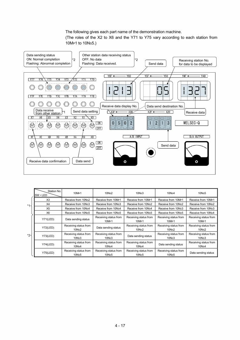
4 - 17
The following gives each part name of the demonstration machine. (The roles of the X2 to X6 and the Y71 to Y75 vary according to each station from 10MP1 to 10NS5.)
Receiving station No.for data to be displayedSend data
Receive data
Data send destination No.
Send data
Receive data display No.
OFF: No dataOther station data receiving status
Flashing: Data received.*2ON: Normal completion
Data sending status
Flashing: Abnormal completion
Data send
Data receivefrom other station *1
Receive data confirmation
Send data setting
*2
Station No. SW • LED
10MP1 10NS2 10NS3 10NS4 10NS5
X3 Receive from 10NS2 Receive from 10MP1 Receive from 10MP1 Receive from 10MP1 Receive from 10MP1 X4 Receive from 10NS3 Receive from 10NS3 Receive from 10NS2 Receive from 10NS2 Receive from 10NS2 X5 Receive from 10NS4 Receive from 10NS4 Receive from 10NS4 Receive from 10NS3 Receive from 10NS3
*1
X6 Receive from 10NS5 Receive from 10NS5 Receive from 10NS5 Receive from 10NS5 Receive from 10NS4
Y71(LED) Data sending status Receiving status from
10MP1 Receiving status from
10MP1 Receiving status from
10MP1 Receiving status from
10MP1
Y72(LED) Receiving status from
10NS2 Data sending status
Receiving status from 10NS2
Receiving status from 10NS2
Receiving status from 10NS2
Y73(LED) Receiving status from
10NS3 Receiving status from
10NS3 Data sending status
Receiving status from 10NS3
Receiving status from 10NS3
Y74(LED) Receiving status from
10NS4 Receiving status from
10NS4 Receiving status from
10NS4 Data sending status
Receiving status from 10NS4
*2
Y75(LED) Receiving status from
10NS5 Receiving status from
10NS5 Receiving status from
10NS5 Receiving status from
10NS5 Data sending status
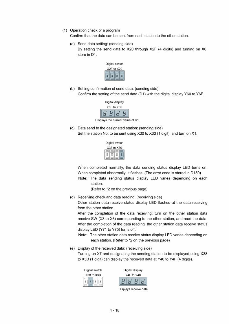
4 - 18
(1) Operation check of a program
Confirm that the data can be sent from each station to the other station.
(a) Send data setting: (sending side) By setting the send data to X20 through X2F (4 digits) and turning on X0, store in D1.
Digital switchX2F to X20
(b) Setting confirmation of send data: (sending side)
Confirm the setting of the send data (D1) with the digital display Y60 to Y6F.
Digital displayY6F to Y60
Displays the current value of D1.
(c) Data send to the designated station: (sending side)
Set the station No. to be sent using X30 to X33 (1 digit), and turn on X1.
Digital switchX33 to X30
When completed normally, the data sending status display LED turns on. When completed abnormally, it flashes. (The error code is stored in D150) Note: The data sending status display LED varies depending on each
station. (Refer to *2 on the previous page)
(d) Receiving check and data reading: (receiving side)
Other station data receive status display LED flashes at the data receiving from the other station. After the completion of the data receiving, turn on the other station data receive SW (X3 to X6) corresponding to the other station, and read the data. After the completion of the data reading, the other station data receive status display LED (Y71 to Y75) turns off. Note: The other station data receive status display LED varies depending on
each station. (Refer to *2 on the previous page)
(e) Display of the received data: (receiving side) Turning on X7 and designating the sending station to be displayed using X38 to X3B (1 digit) can display the received data at Y40 to Y4F (4 digits).
Digital displayY4F to Y40
Displays receive data
Digital switchX38 to X3B
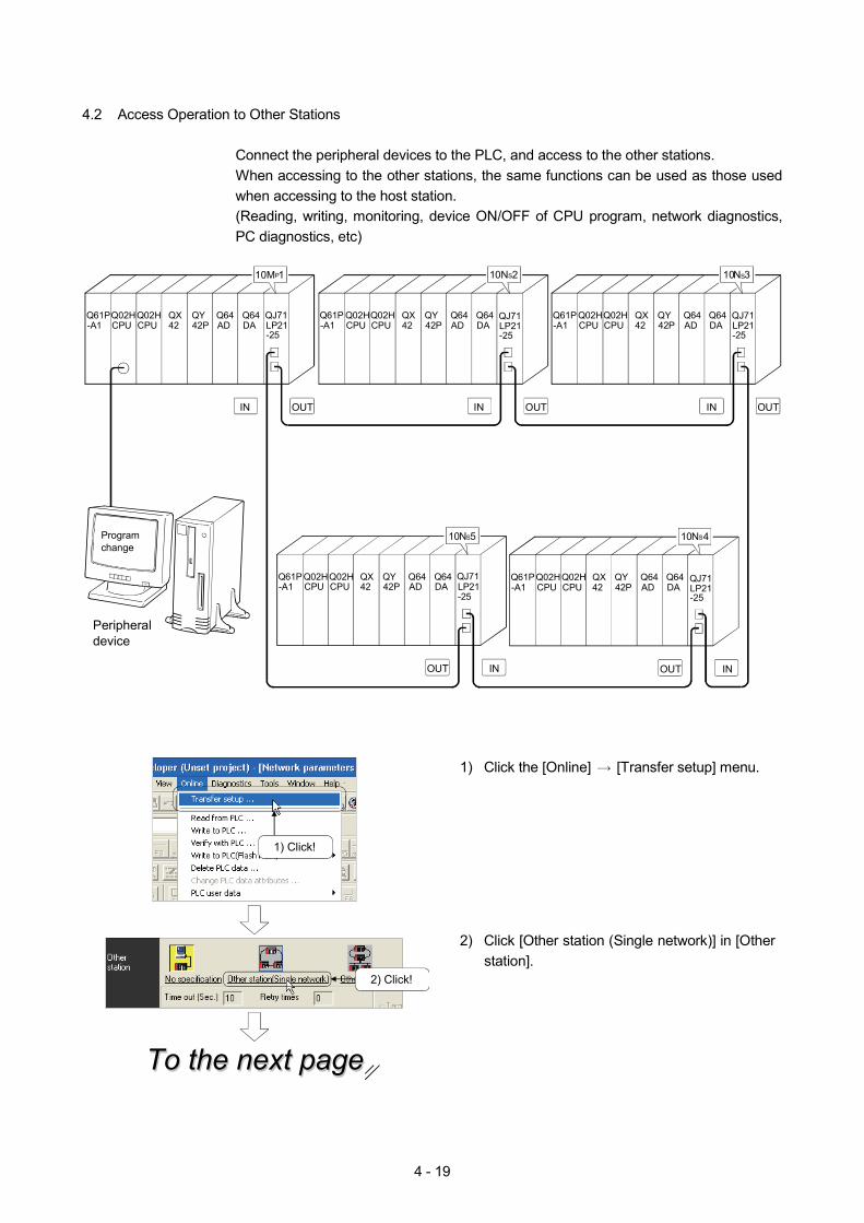
4 - 19
4.2 Access Operation to Other Stations
Connect the peripheral devices to the PLC, and access to the other stations. When accessing to the other stations, the same functions can be used as those used when accessing to the host station. (Reading, writing, monitoring, device ON/OFF of CPU program, network diagnostics, PC diagnostics, etc)
10NS5
Q64DA
Q64AD
QY42P
Q02HCPU
QX42
Q61P-A1
Q02HCPU
10NS4
Q64DA
Q64AD
QY42P
Q02HCPU
QX42
Q61P-A1
Q02HCPU
10NS3
Q64DA
Q64AD
QY42P
Q02HCPU
QX42
Q61P-A1
Q02HCPU
10NS2
Q64DA
Q64AD
QY42P
Q02HCPU
QX42
Q61P-A1
Q02HCPU
10MP1
OUT OUTIN OUTIN
OUT IN OUT IN
IN
QJ71LP21-25
Q64DA
Q64AD
QY42P
Q02HCPU
QX42
Q61P-A1
Q02HCPU
QJ71LP21-25
QJ71LP21-25
QJ71LP21-25
QJ71LP21-25
Peripheral device
Program change
1) Click the [Online] [Transfer setup] menu.
1) Click!
To the next pageTo the next pageTo the next page
2) Click!
2) Click [Other station (Single network)] in [Other
station].
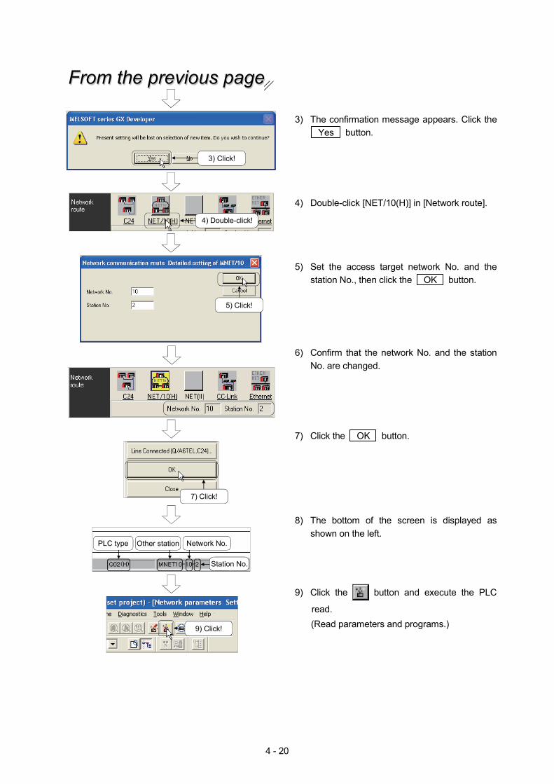
4 - 20
3) The confirmation message appears. Click the Yes button.
4) Double-click [NET/10(H)] in [Network route].
5) Set the access target network No. and the station No., then click the OK button.
6) Confirm that the network No. and the station No. are changed.
7) Click the OK button.
8) The bottom of the screen is displayed as shown on the left.
4) Double-click!
Network No.PLC type Other station
Station No.
From the previous pageFrom the previous pageFrom the previous page
3) Click!
5) Click!
7) Click!
9) Click!
9) Click the button and execute the PLC
read. (Read parameters and programs.)
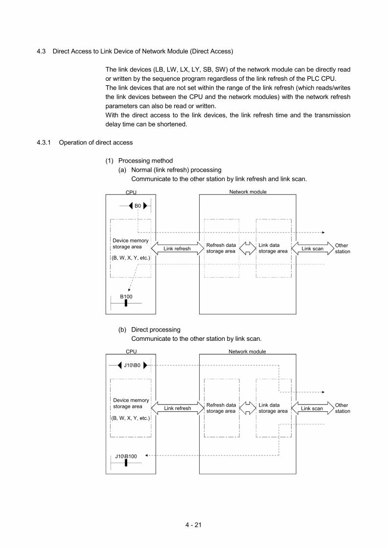
4 - 21
4.3 Direct Access to Link Device of Network Module (Direct Access)
The link devices (LB, LW, LX, LY, SB, SW) of the network module can be directly read or written by the sequence program regardless of the link refresh of the PLC CPU. The link devices that are not set within the range of the link refresh (which reads/writes the link devices between the CPU and the network modules) with the network refresh parameters can also be read or written. With the direct access to the link devices, the link refresh time and the transmission delay time can be shortened.
4.3.1 Operation of direct access
(1) Processing method (a) Normal (link refresh) processing
Communicate to the other station by link refresh and link scan.
CPU
Other station
B100
Network module
B0
Device memory storage area
(B, W, X, Y, etc.)
Link refreshRefresh data storage area
Link data storage area Link scan
(b) Direct processing
Communicate to the other station by link scan.
CPU
Other station
J10\B100
Network module
Device memory storage area
(B, W, X, Y, etc.)
Link refresh Refresh data storage area
Link data storage area Link scan
J10\B0
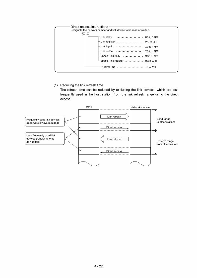
4 - 22
Link relay
Link register
Link input
Link output
Special link relay
Special link register
Network No
\
Direct access instructionsDesignate the network number and link device to be read or written.
B0 to 3FFF
W0 to 3FFF
X0 to 1FFF
Y0 to 1FFF
SB0 to 1FF
SW0 to 1FF
1 to 239
(1) Reducing the link refresh time The refresh time can be reduced by excluding the link devices, which are less frequently used in the host station, from the link refresh range using the direct access.
CPU
Link refresh
Network module
Link refresh
Direct access
Direct access
Send range to other stations
Receive range from other stations
Less frequently used link devices (read/write only as needed)
Frequently used link devices (read/write always required)
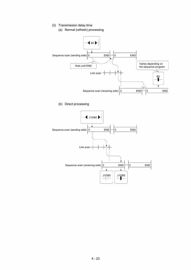
4 - 23
(2) Transmission delay time
(a) Normal (refresh) processing
0 END
B0
B0
0 ENDSequence scan (sending side)
Link scan
0 ENDSequence scan (receiving side)
Wait until END
0 END
Varies depending on the sequence program
(b) Direct processing
0 ENDSequence scan (sending side)
Link scan
0 ENDSequence scan (receiving side)
0 END
J10\B0
0 END
J10\B0
J10\B0
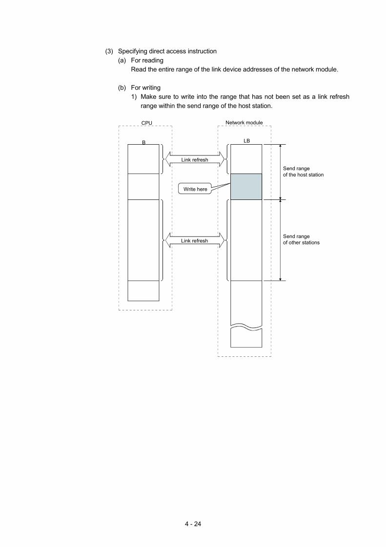
4 - 24
(3) Specifying direct access instruction
(a) For reading Read the entire range of the link device addresses of the network module.
(b) For writing
1) Make sure to write into the range that has not been set as a link refresh range within the send range of the host station.
LB
Network module
B
Link refresh
CPU
Write here
Link refresh
Send range of the host station
Send range of other stations
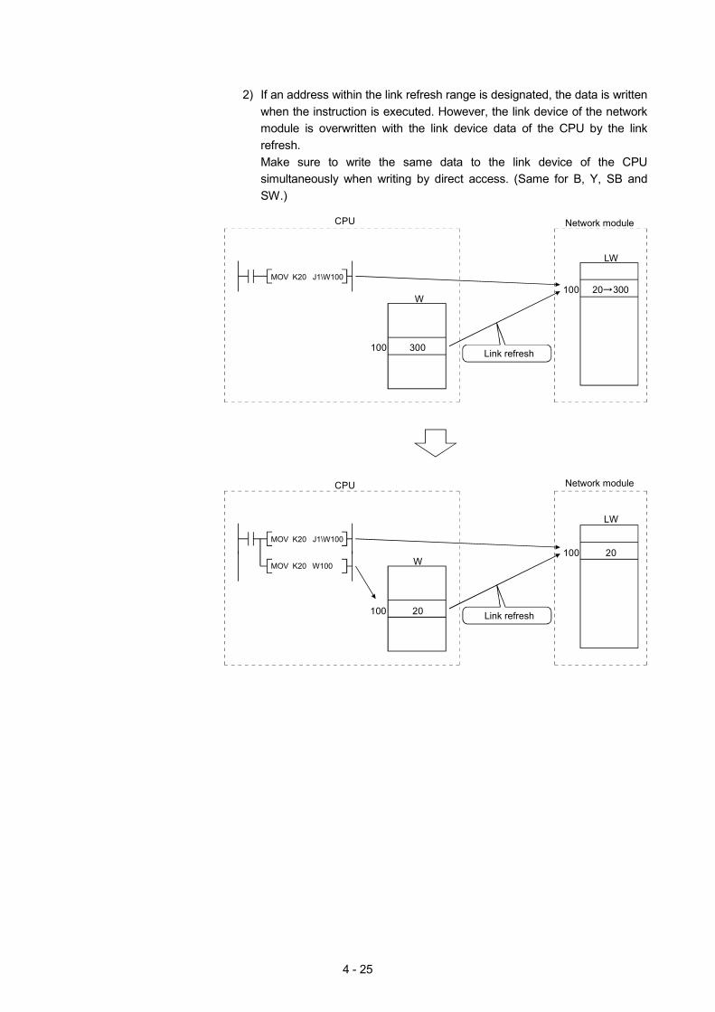
4 - 25
2) If an address within the link refresh range is designated, the data is written
when the instruction is executed. However, the link device of the network module is overwritten with the link device data of the CPU by the link refresh. Make sure to write the same data to the link device of the CPU simultaneously when writing by direct access. (Same for B, Y, SB and SW.)
CPU
20 300
LW
Network module
100
300
W
100
MOV K20 J1\W100
Link refresh
CPU
20
LW
Network module
100
20
W
100
MOV K20 J1\W100
MOV K20 W100
Link refresh
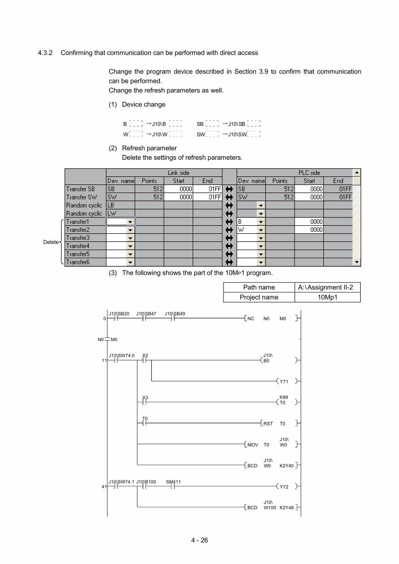
4 - 26
4.3.2 Confirming that communication can be performed with direct access
Change the program device described in Section 3.9 to confirm that communication can be performed. Change the refresh parameters as well.
(1) Device change
B J10\B
W J10\W
SB J10\SB
SW J10\SW
(2) Refresh parameter
Delete the settings of refresh parameters.
Delete
(3) The following shows the part of the 10MP1 program.
Path name A: Assignment II-2 Project name 10Mp1
0J10\SB20
X2
X3
T0
41
M0
J10\SW74.011
J10\SB47 J10\SB49
J10\SW74.1 J10\B100 SM411
B0
Y71
T0
Y72
M0N0NC
J10\
K99
T0RST
W0T0MOVJ10\
K2Y40W0BCD
K2Y48W100BCDJ10\
J10\
N0
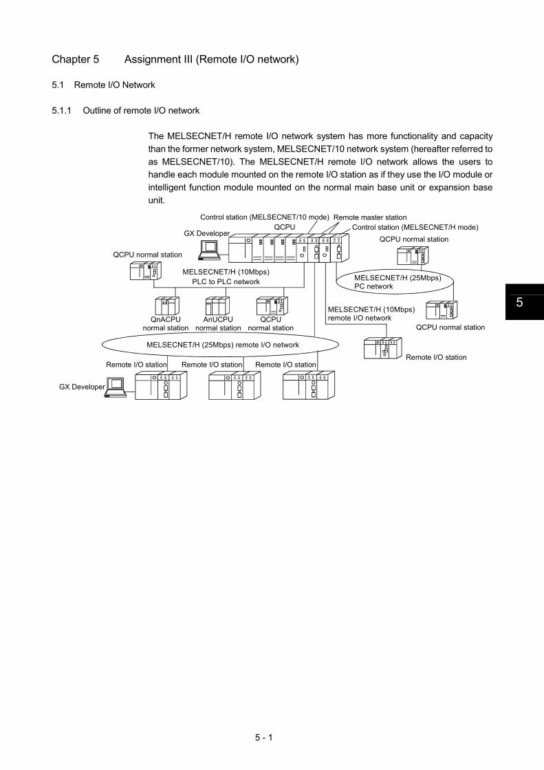
5 - 1
5
Chapter 5 Assignment III (Remote I/O network)
5.1 Remote I/O Network
5.1.1 Outline of remote I/O network
The MELSECNET/H remote I/O network system has more functionality and capacity than the former network system, MELSECNET/10 network system (hereafter referred to as MELSECNET/10). The MELSECNET/H remote I/O network allows the users to handle each module mounted on the remote I/O station as if they use the I/O module or intelligent function module mounted on the normal main base unit or expansion base unit.
Remote I/O station
QCPUGX Developer
Control station (MELSECNET/10 mode)Control station (MELSECNET/H mode)
GX Developer
QCPU normal station
QCPU normal station
QCPU normal station
Remote I/O station Remote I/O station Remote I/O station
MELSECNET/H (25Mbps)PC network
Remote master station
MELSECNET/H (10Mbps)remote I/O network
MELSECNET/H (25Mbps) remote I/O network
MELSECNET/H (10Mbps)PLC to PLC network
QnACPU normal station
AnUCPU normal station
QCPU normal station
5 - 2
POINT (1) Select the QCPU when a PLC is selected for the MELSECNET/H remote I/O
network. (2) The remote I/O network and the PLC to PLC network cannot be mixed on the
same MELSECNET/H network. Always build separate networks. (3) Only MELSECNET/H network modules can be connected to the
MELSECNET/H remote I/O network. They cannot be mixed with MELSECNET/10 network modules.
5.1.2 Features of remote I/O network
The MELSECNET/H remote I/O network has the following features.
(1) Achievement of a high-speed communication system (a) High-speed data sending at a communication rate of 10Mbps/25Mbps is
possible. (25Mbps is available for only the optical loop type.)
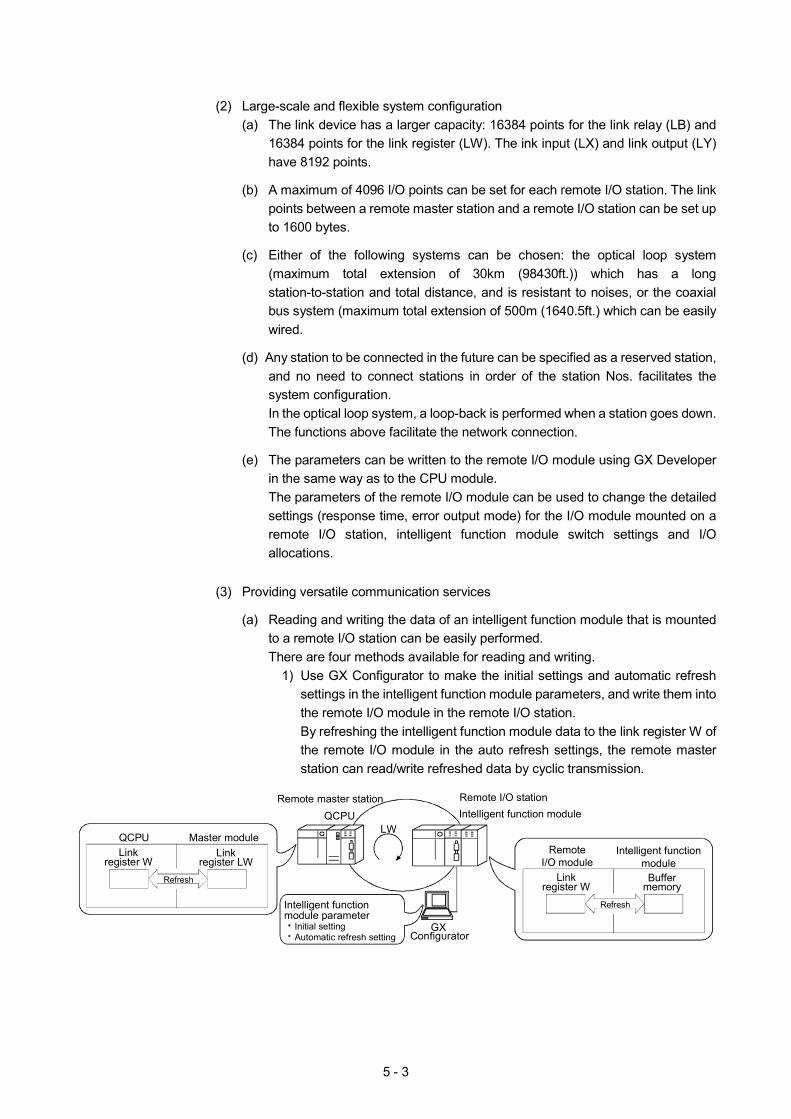
5 - 3
(2) Large-scale and flexible system configuration
(a) The link device has a larger capacity: 16384 points for the link relay (LB) and 16384 points for the link register (LW). The ink input (LX) and link output (LY) have 8192 points.
(b) A maximum of 4096 I/O points can be set for each remote I/O station. The link
points between a remote master station and a remote I/O station can be set up to 1600 bytes.
(c) Either of the following systems can be chosen: the optical loop system
(maximum total extension of 30km (98430ft.)) which has a long station-to-station and total distance, and is resistant to noises, or the coaxial bus system (maximum total extension of 500m (1640.5ft.) which can be easily wired.
(d) Any station to be connected in the future can be specified as a reserved station,
and no need to connect stations in order of the station Nos. facilitates the system configuration. In the optical loop system, a loop-back is performed when a station goes down. The functions above facilitate the network connection.
(e) The parameters can be written to the remote I/O module using GX Developer
in the same way as to the CPU module. The parameters of the remote I/O module can be used to change the detailed settings (response time, error output mode) for the I/O module mounted on a remote I/O station, intelligent function module switch settings and I/O allocations.
(3) Providing versatile communication services
(a) Reading and writing the data of an intelligent function module that is mounted
to a remote I/O station can be easily performed. There are four methods available for reading and writing.
1) Use GX Configurator to make the initial settings and automatic refresh settings in the intelligent function module parameters, and write them into the remote I/O module in the remote I/O station. By refreshing the intelligent function module data to the link register W of the remote I/O module in the auto refresh settings, the remote master station can read/write refreshed data by cyclic transmission.
QCPURemote master station Remote I/O station
Intelligent function moduleLW
GXConfigurator
Intelligent functionmodule parameter
Initial settingAutomatic refresh setting
RemoteI/O module
Intelligent functionmodule
Linkregister W
Buffermemory
Refresh
QCPU Master moduleLink
register WLink
register LWRefresh
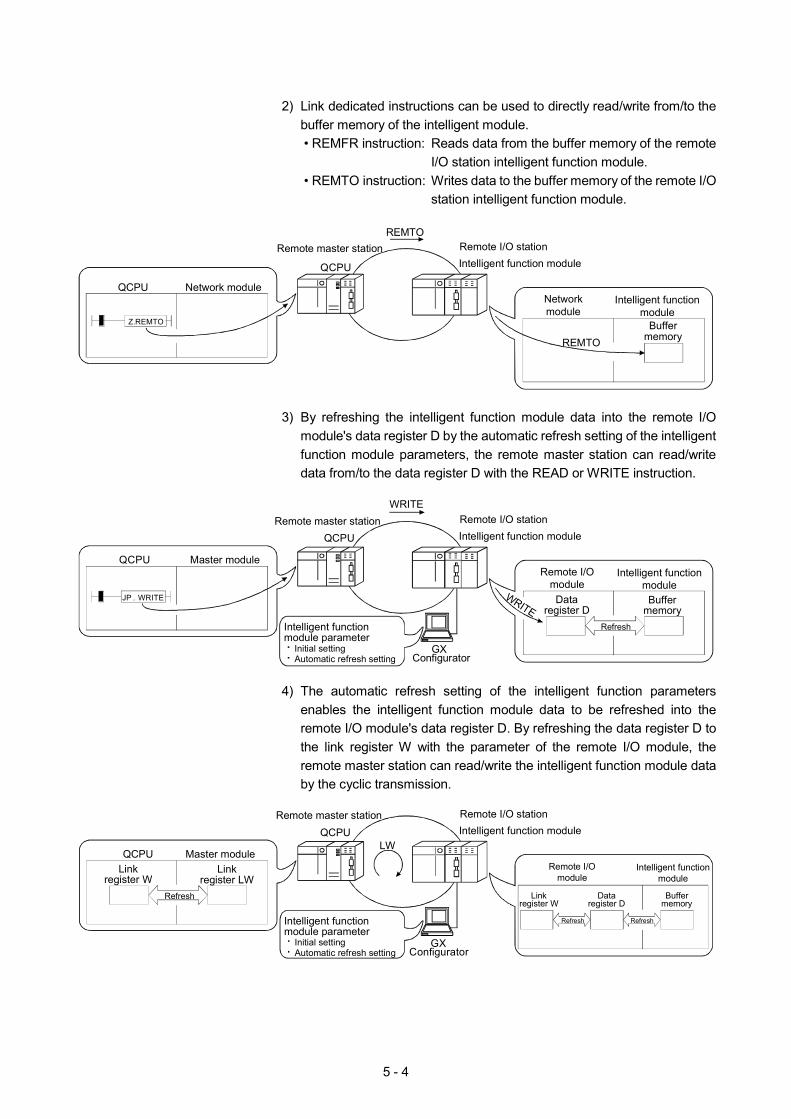
5 - 4
2) Link dedicated instructions can be used to directly read/write from/to the
buffer memory of the intelligent module. • REMFR instruction: Reads data from the buffer memory of the remote
I/O station intelligent function module. • REMTO instruction: Writes data to the buffer memory of the remote I/O
station intelligent function module.
QCPU
Remote master station Remote I/O stationIntelligent function module
REMTO
Networkmodule
Intelligent functionmodule
BuffermemoryREMTO
QCPU Network module
Z.REMTO
3) By refreshing the intelligent function module data into the remote I/O
module's data register D by the automatic refresh setting of the intelligent function module parameters, the remote master station can read/write data from/to the data register D with the READ or WRITE instruction.
QCPURemote master station Remote I/O station
Intelligent function module
GXConfigurator
Intelligent functionmodule parameter
Initial settingAutomatic refresh setting
Remote I/Omodule
Intelligent functionmodule
Dataregister D
Buffermemory
Refresh
QCPU Master module
WRITE
JP . WRITE WRITE
4) The automatic refresh setting of the intelligent function parameters
enables the intelligent function module data to be refreshed into the remote I/O module's data register D. By refreshing the data register D to the link register W with the parameter of the remote I/O module, the remote master station can read/write the intelligent function module data by the cyclic transmission.
QCPURemote master station Remote I/O station
Intelligent function moduleLW
GXConfigurator
Intelligent functionmodule parameter
Initial settingAutomatic refresh setting
Remote I/Omodule
Intelligent functionmodule
Linkregister W
Refresh
QCPU Master moduleLink
register WLink
register LWRefresh Data
register DBuffer
memory
Refresh
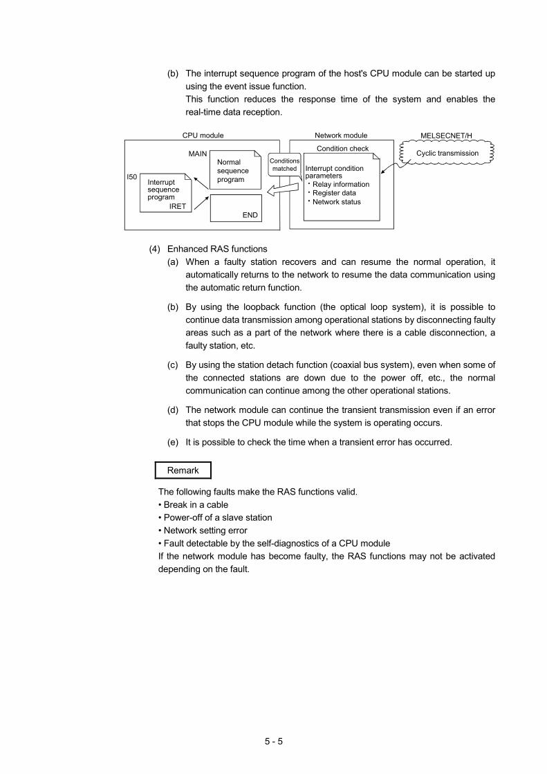
5 - 5
(b) The interrupt sequence program of the host's CPU module can be started up
using the event issue function. This function reduces the response time of the system and enables the real-time data reception.
END
MAIN
I50
CPU module Network module
Cyclic transmission
MELSECNET/H
Normal sequence program
Condition check
Interrupt condition parameters
Relay informationRegister dataNetwork status
Conditionsmatched
Interrupt sequence program
IRET
(4) Enhanced RAS functions
(a) When a faulty station recovers and can resume the normal operation, it automatically returns to the network to resume the data communication using the automatic return function.
(b) By using the loopback function (the optical loop system), it is possible to
continue data transmission among operational stations by disconnecting faulty areas such as a part of the network where there is a cable disconnection, a faulty station, etc.
(c) By using the station detach function (coaxial bus system), even when some of
the connected stations are down due to the power off, etc., the normal communication can continue among the other operational stations.
(d) The network module can continue the transient transmission even if an error
that stops the CPU module while the system is operating occurs.
(e) It is possible to check the time when a transient error has occurred.
Remark
The following faults make the RAS functions valid. • Break in a cable • Power-off of a slave station • Network setting error • Fault detectable by the self-diagnostics of a CPU module If the network module has become faulty, the RAS functions may not be activated depending on the fault.
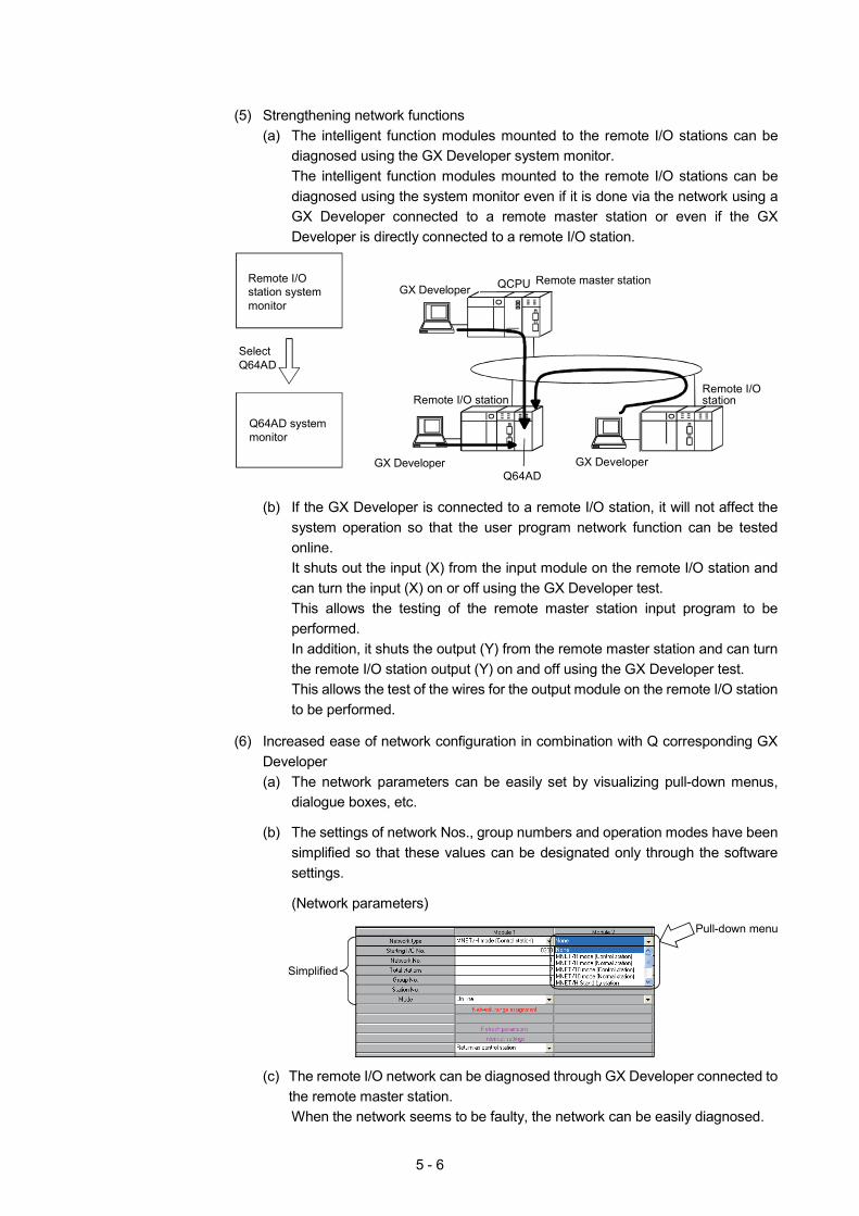
5 - 6
(5) Strengthening network functions
(a) The intelligent function modules mounted to the remote I/O stations can be diagnosed using the GX Developer system monitor. The intelligent function modules mounted to the remote I/O stations can be diagnosed using the system monitor even if it is done via the network using a GX Developer connected to a remote master station or even if the GX Developer is directly connected to a remote I/O station.
QCPUGX DeveloperRemote master station
Remote I/O stationRemote I/O station
GX Developer GX DeveloperQ64AD
Select Q64AD
Remote I/O station system monitor
Q64AD system monitor
(b) If the GX Developer is connected to a remote I/O station, it will not affect the
system operation so that the user program network function can be tested online. It shuts out the input (X) from the input module on the remote I/O station and can turn the input (X) on or off using the GX Developer test. This allows the testing of the remote master station input program to be performed. In addition, it shuts the output (Y) from the remote master station and can turn the remote I/O station output (Y) on and off using the GX Developer test. This allows the test of the wires for the output module on the remote I/O station to be performed.
(6) Increased ease of network configuration in combination with Q corresponding GX
Developer (a) The network parameters can be easily set by visualizing pull-down menus,
dialogue boxes, etc.
(b) The settings of network Nos., group numbers and operation modes have been simplified so that these values can be designated only through the software settings.
(Network parameters)
Pull-down menu
Simplified
(c) The remote I/O network can be diagnosed through GX Developer connected to the remote master station. When the network seems to be faulty, the network can be easily diagnosed.
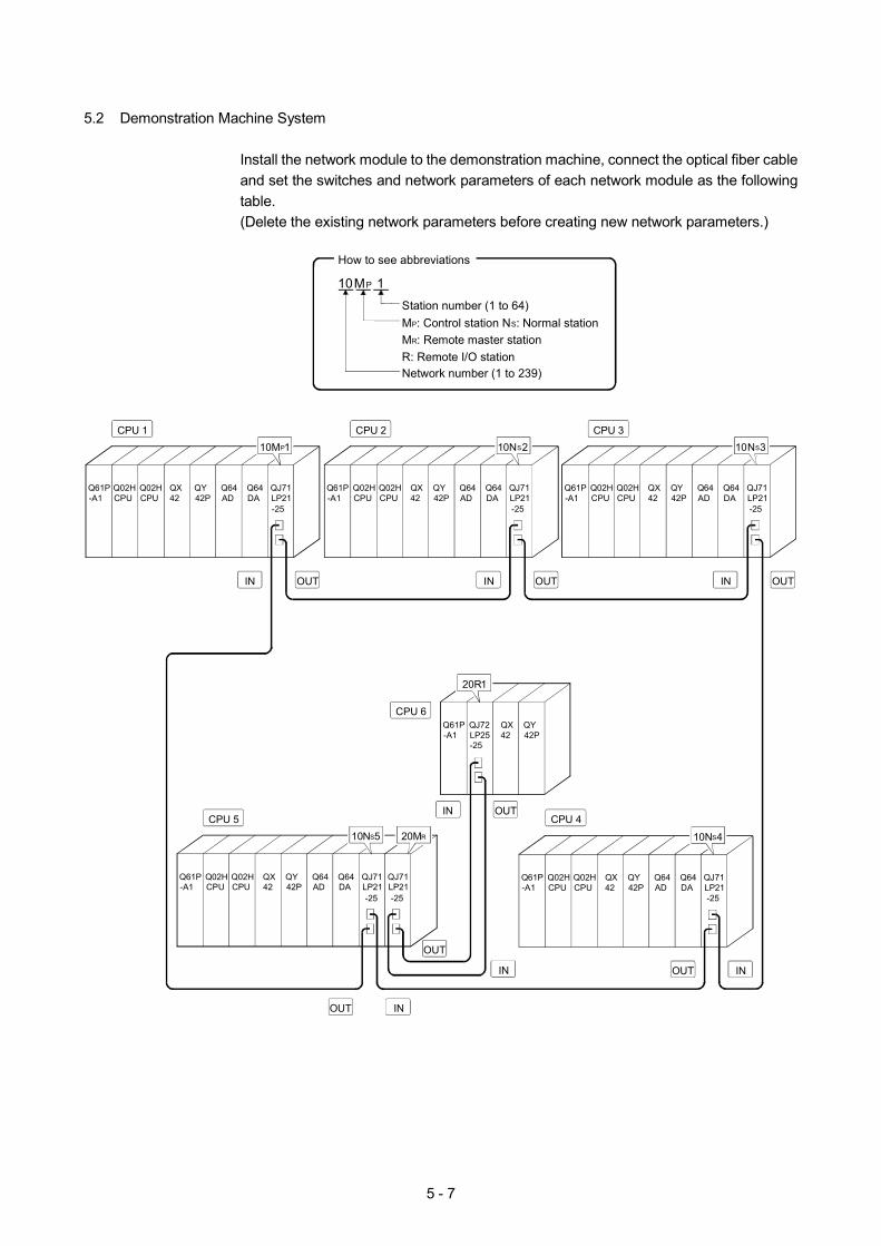
5 - 7
5.2 Demonstration Machine System
Install the network module to the demonstration machine, connect the optical fiber cable and set the switches and network parameters of each network module as the following table. (Delete the existing network parameters before creating new network parameters.)
QY42P
10NS5
QJ71LP21
Q64DA
Q64AD
QY42P
Q02HCPU
QX42
Q61P-A1
Q02HCPU
10NS4
QJ71LP21
Q64DA
Q64AD
QY42P
Q02HCPU
QX42
Q61P-A1
Q02HCPU
10NS3
QJ71LP21
Q64DA
Q64AD
QY42P
Q02HCPU
QX42
Q61P-A1
Q02HCPU
10NS2
QJ71LP21
Q64DA
Q64AD
QY42P
Q02HCPU
QX42
Q61P-A1
Q02HCPU
10MP1
OUT OUTIN OUTIN
OUT
OUT
OUT IN
IN
QJ71LP21
Q64DA
Q64AD
QY42P
Q02HCPU
QX42
Q61P-A1
Q02HCPU
Q61P-A1
QJ71LP21
IN
IN
QJ72LP25-25
QX42
20R1
20MR
IN OUT
How to see abbreviations
10MP 1Station number (1 to 64)MP: Control station NS: Normal stationMR: Remote master stationR: Remote I/O stationNetwork number (1 to 239)
CPU 1
CPU 5 CPU 4
CPU 6
CPU 2 CPU 3
-25 -25 -25
-25-25-25
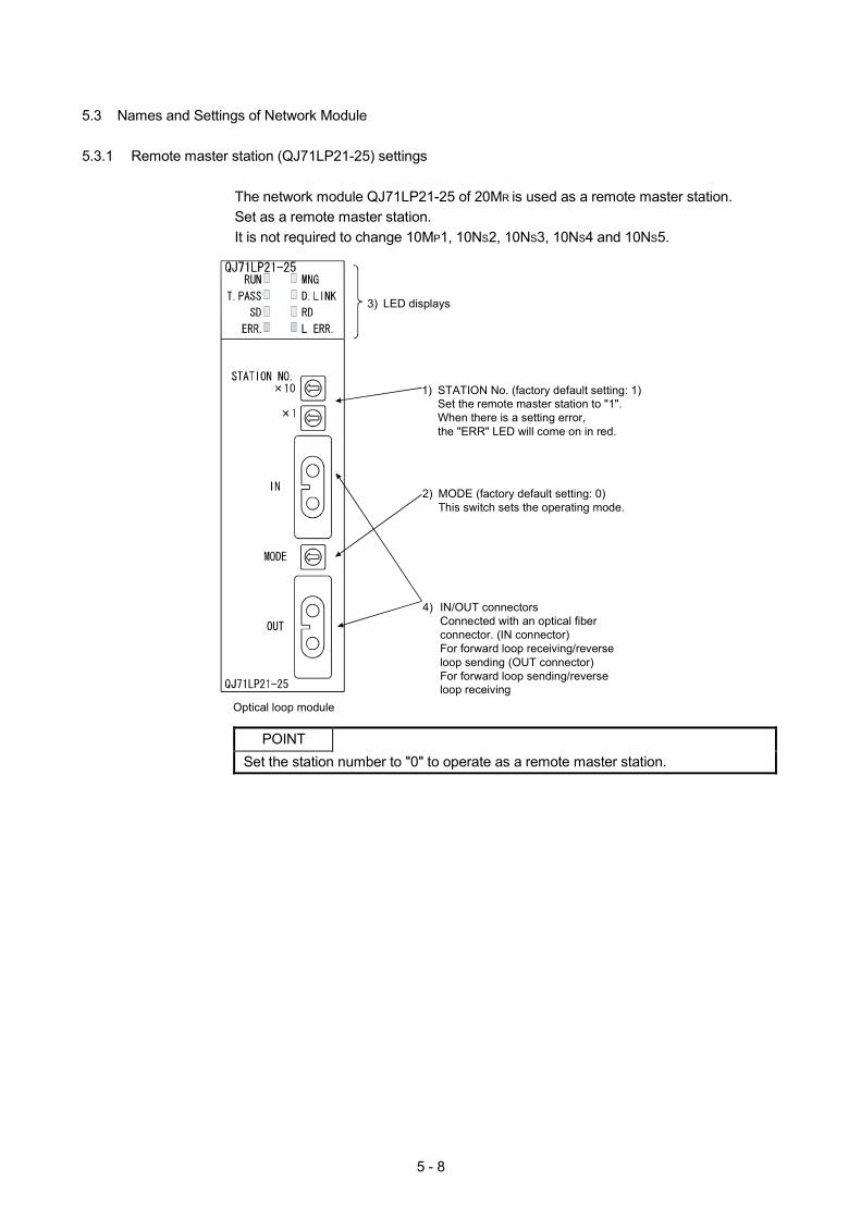
5 - 8
5.3 Names and Settings of Network Module
5.3.1 Remote master station (QJ71LP21-25) settings
The network module QJ71LP21-25 of 20MR is used as a remote master station. Set as a remote master station. It is not required to change 10MP1, 10NS2, 10NS3, 10NS4 and 10NS5.
3) LED displays
1) STATION No. (factory default setting: 1)Set the remote master station to "1".When there is a setting error, the "ERR" LED will come on in red.
2) MODE (factory default setting: 0)This switch sets the operating mode.
4) IN/OUT connectorsConnected with an optical fiber connector. (IN connector)For forward loop receiving/reverse loop sending (OUT connector)For forward loop sending/reverse loop receiving
Optical loop module
POINT
Set the station number to "0" to operate as a remote master station.
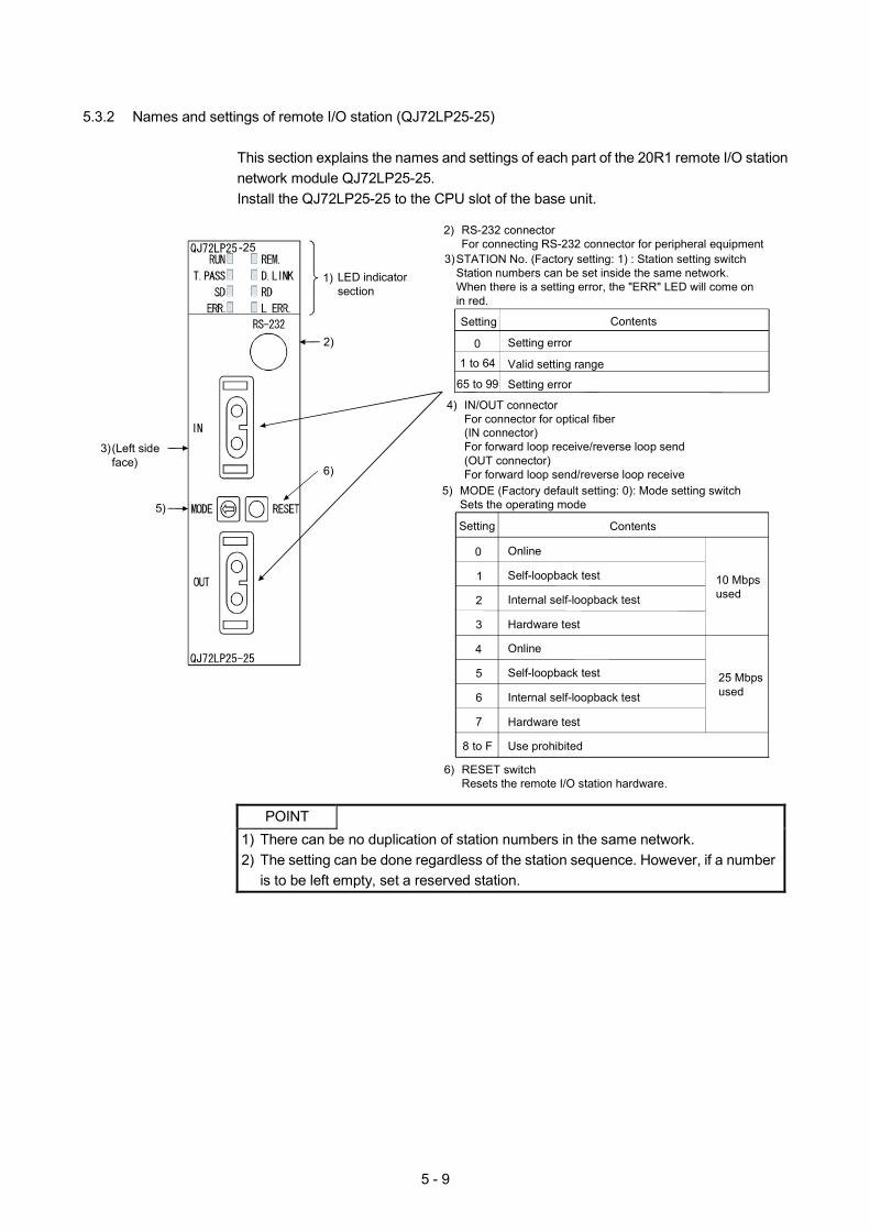
5 - 9
5.3.2 Names and settings of remote I/O station (QJ72LP25-25)
This section explains the names and settings of each part of the 20R1 remote I/O station network module QJ72LP25-25. Install the QJ72LP25-25 to the CPU slot of the base unit.
1) LED indicator section
3)STATION No. (Factory setting: 1) : Station setting switchStation numbers can be set inside the same network.When there is a setting error, the "ERR" LED will come on in red.
Setting
0
1 to 64
65 to 99
Valid setting range
Setting error
Setting error
Contents
5) MODE (Factory default setting: 0): Mode setting switchSets the operating mode
4) IN/OUT connectorFor connector for optical fiber(IN connector)For forward loop receive/reverse loop send(OUT connector)For forward loop send/reverse loop receive
3)(Left side face)
2) RS-232 connectorFor connecting RS-232 connector for peripheral equipment
Setting
0
Contents
Online
Self-loopback test
Use prohibited
Hardware test
Internal self-loopback test
1
2
3
8 to F
10 Mbps used
4 Online
Self-loopback test
Hardware test
Internal self-loopback test
5
6
7
25 Mbps used
6) RESET switchResets the remote I/O station hardware.
-25
2)
5)
6)
POINT
1) There can be no duplication of station numbers in the same network. 2) The setting can be done regardless of the station sequence. However, if a number
is to be left empty, set a reserved station.
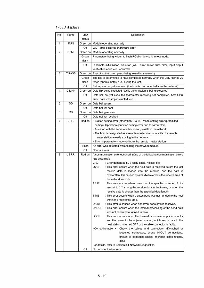
5 - 10
1) LED displays
No. Name LED
status Description
1 RUN Green on Module operating normally Off WDT error occurred (hardware error) 2 REM. Green on Module operating normally
Green flash
Parameters being written to flash ROM or device is in test mode.
Off In remote initialization, an error (WDT error, blown fuse error, input/output verification error, etc.) occurred.
3 T.PASS Green on Executing the baton pass (being joined in a network) Green
flash The test is determined to have completed normally when this LED flashes 20 times (approximately 10s) during the test.
Off Baton pass not yet executed (the host is disconnected from the network) 4 D.LINK Green on Data link being executed (cyclic transmission is being executed) Off Data link not yet executed (parameter receiving not completed, host CPU
error, data link stop instructed, etc.) 5 SD Green on Data being sent Off Data not yet sent 6 RD Green on Data being received Off Data not yet received
Red on • Station setting error (other than 1 to 64), Mode setting error (prohibited setting), Operation condition setting error due to parameters.
• A station with the same number already exists in the network. • The host is designated as a remote master station in spite of a remote
master station already existing in the network. • Error in parameters received from the remote master station.
Flash An error was detected while testing the network module.
7 ERR.
Off Normal status 8 L ERR. Red on A communication error occurred. (One of the following communication errors
has occurred): CRC : Error generated by a faulty cable, noises, etc. OVER : This error occurs when the next data is received before the last
receive data is loaded into the module, and the data is overwritten. It is caused by a hardware error in the receive area of the network module.
AB.IF : This error occurs when more than the specified number of bits are set to "1" among the receive data in the frame, or when the receive data is shorter than the specified data length.
TIME : This error occurs when a baton pass was not handed to the host within the monitoring time.
DATA : This error is caused when abnormal code data is received. UNDER : This error occurs when the internal processing of the send data
was not executed at a fixed interval. LOOP : This error occurs when the forward or reverse loop line is faulty
and the power to the adjacent station, which sends data to the host station, is turned OFF or the cable connector is faulty.
<Corrective action> Check the cables and connectors. (Detached or loosened connectors, wrong IN/OUT connections, broken or damaged cables, improper cable routing, etc.)
For details, refer to Section 8.1 Network Diagnostics. Off No communication error
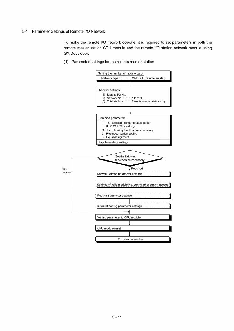
5 - 11
5.4 Parameter Settings of Remote I/O Network
To make the remote I/O network operate, it is required to set parameters in both the remote master station CPU module and the remote I/O station network module using GX Developer.
(1) Parameter settings for the remote master station
Network settings
1) Starting I/O No.2) Network No. 1 to 2393) Total stations Remote master station only
Setting the number of module cards
Network type MNET/H (Remote master)
Set the followingfunctions as necessary.
Network refresh parameter settings
Settings of valid module No. during other station access
Writing parameter to CPU module
Not required
Required
To cable connection
Routing parameter settings
Interrupt setting parameter settings
Common parameters1) Transmission range of each station
(LB/LW, LX/LY setting)Set the following functions as necessary.2) Reserved station setting3) Equal assignment
Supplementary settings
CPU module reset
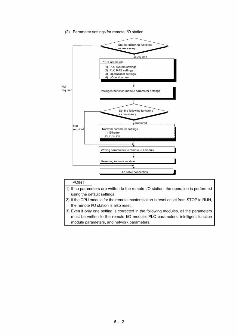
5 - 12
(2) Parameter settings for remote I/O station
Set the following functionsas necessary.
Network parameter settings1) Ethernet2) CC-Link
Writing parameters to remote I/O module
Notrequired
Required
To cable connection
PLC Parameters
1) PLC system settings2) PLC RAS settings3) Operational settings4) I/O assignment
Set the following functionsas necessary.
Required
Notrequired Intelligent function module parameter settings
Resetting network module
POINT
1) If no parameters are written to the remote I/O station, the operation is performed using the default settings.
2) If the CPU module for the remote master station is reset or set from STOP to RUN, the remote I/O station is also reset.
3) Even if only one setting is corrected in the following modules, all the parameters must be written to the remote I/O module: PLC parameters, intelligent function module parameters, and network parameters.
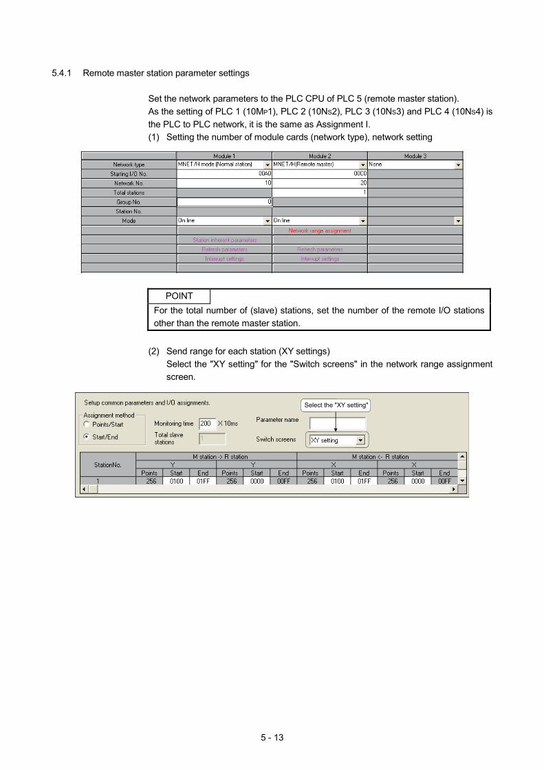
5 - 13
5.4.1 Remote master station parameter settings
Set the network parameters to the PLC CPU of PLC 5 (remote master station). As the setting of PLC 1 (10MP1), PLC 2 (10NS2), PLC 3 (10NS3) and PLC 4 (10NS4) is the PLC to PLC network, it is the same as Assignment I. (1) Setting the number of module cards (network type), network setting
POINT
For the total number of (slave) stations, set the number of the remote I/O stations other than the remote master station.
(2) Send range for each station (XY settings)
Select the "XY setting" for the "Switch screens" in the network range assignment screen.
Select the "XY setting"
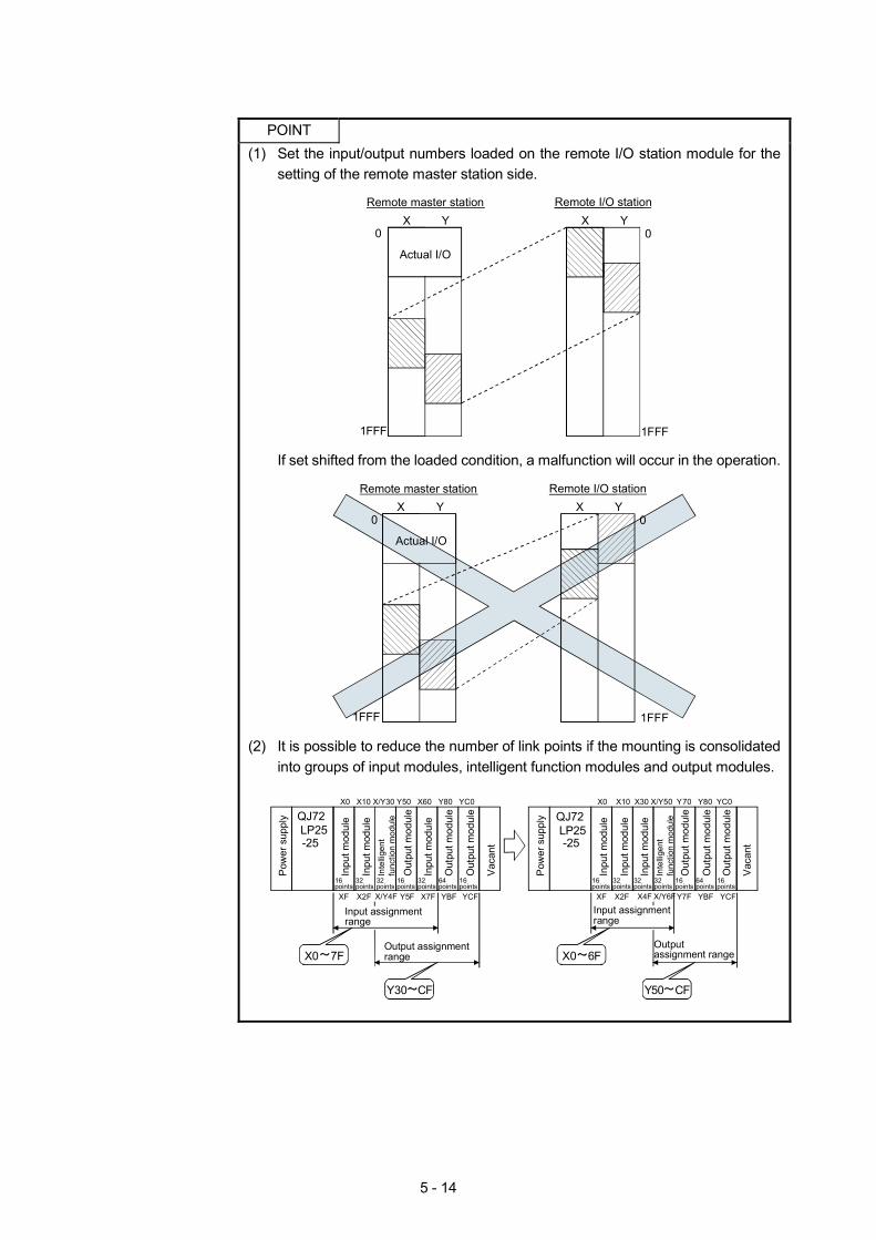
5 - 14
POINT (1) Set the input/output numbers loaded on the remote I/O station module for the
setting of the remote master station side.
Remote master station Remote I/O station
0
1FFF
0
1FFF
Actual I/O
X Y X Y
If set shifted from the loaded condition, a malfunction will occur in the operation.
Remote master station Remote I/O station
0
1FFF
0
1FFF
Actual I/O
X Y X Y
(2) It is possible to reduce the number of link points if the mounting is consolidated
into groups of input modules, intelligent function modules and output modules.
Pow
er s
uppl
y
Pow
er s
uppl
yQJ72 LP25
Inpu
t mod
ule
Inpu
t mod
ule
Inpu
t mod
ule
Out
put m
odul
e
Out
put m
odul
e
Vac
ant
Vac
ant
Out
put m
odul
e
XF
16points
Inpu
t mod
ule
16points
16points
16points
Out
put m
odul
e
16points
Out
put m
odul
e
16points
32points
Inpu
t mod
ule
32points
Inpu
t mod
ule
32points
32points
32points
64points
Out
put m
odul
e
64points
X2F Y5F YCFYBFX/Y4F X7F
Inte
llige
nt
func
tion
mod
ule
32points
Inte
llige
nt
func
tion
mod
ule
Input assignment range
Output assignment rangeX0 7F
Y30 CF
QJ72 LP25
XF X2F YCFYBFX4F Y7F
Input assignment range
Output assignment rangeX0 6F
Y50 CF
X0 X10 X/Y30 Y50 X60 Y80 YC0 X0 X10 X30 X/Y50 Y70 Y80 YC0
X/Y6F
-25 -25
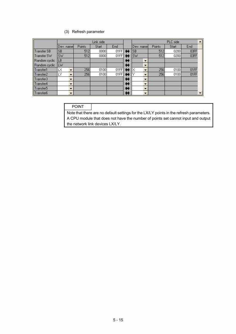
5 - 15
(3) Refresh parameter
POINT
Note that there are no default settings for the LX/LY points in the refresh parameters. A CPU module that does not have the number of points set cannot input and output the network link devices LX/LY.
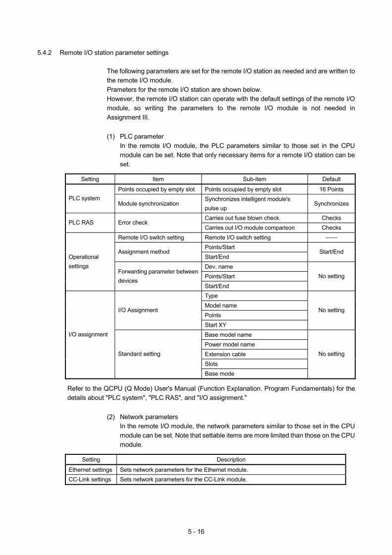
5 - 16
5.4.2 Remote I/O station parameter settings
The following parameters are set for the remote I/O station as needed and are written to the remote I/O module. Prameters for the remote I/O station are shown below. However, the remote I/O station can operate with the default settings of the remote I/O module, so writing the parameters to the remote I/O module is not needed in Assignment III.
(1) PLC parameter
In the remote I/O module, the PLC parameters similar to those set in the CPU module can be set. Note that only necessary items for a remote I/O station can be set.
Setting Item Sub-item Default
Points occupied by empty slot Points occupied by empty slot 16 Points PLC system
Module synchronization Synchronizes intelligent module's pulse up
Synchronizes
Carries out fuse blown check Checks PLC RAS Error check
Carries out I/O module comparison Checks Remote I/O switch setting Remote I/O switch setting ——
Points/Start Assignment method
Start/End Start/End
Dev. name Points/Start
Operational settings
Forwarding parameter between devices
Start/End
No setting
Type Model name Points
I/O Assignment
Start XY
No setting
Base model name Power model name Extension cable Slots
I/O assignment
Standard setting
Base mode
No setting
Refer to the QCPU (Q Mode) User's Manual (Function Explanation. Program Fundamentals) for the details about "PLC system", "PLC RAS", and "I/O assignment."
(2) Network parameters
In the remote I/O module, the network parameters similar to those set in the CPU module can be set. Note that settable items are more limited than those on the CPU module.
Setting Description
Ethernet settings Sets network parameters for the Ethernet module. CC-Link settings Sets network parameters for the CC-Link module.
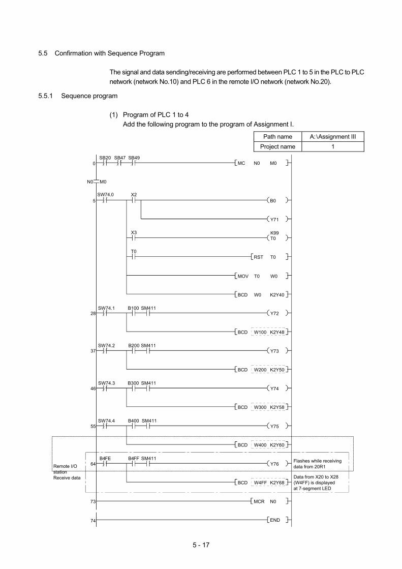
5 - 17
5.5 Confirmation with Sequence Program
The signal and data sending/receiving are performed between PLC 1 to 5 in the PLC to PLC network (network No.10) and PLC 6 in the remote I/O network (network No.20).
5.5.1 Sequence program
(1) Program of PLC 1 to 4 Add the following program to the program of Assignment I.
Path name A: Assignment III
Project name 1
0SB20 SB47 SB49
Remote I/O stationReceive data
N0 M0
X2SW74.05 B0
Y71
M0N0MC
X3T0K99
SW74.1 B100 SM41128 Y72
SW74.2 B200 SM41137 Y73
SW74.3 B300 SM41146 Y74
SW74.4 B400 SM41155 Y75
T0T0RST
W0T0MOV
K2Y40W0BCD
73 N0MCR
74 END
K2Y48W100BCD
K2Y50W200BCD
K2Y58W300BCD
K2Y60W400BCD
Flashes while receiving data from 20R1
B4FE B4FF SM41164 Y76
Data from X20 to X28 (W4FF) is displayed at 7-segment LED
K2Y68W4FFBCD
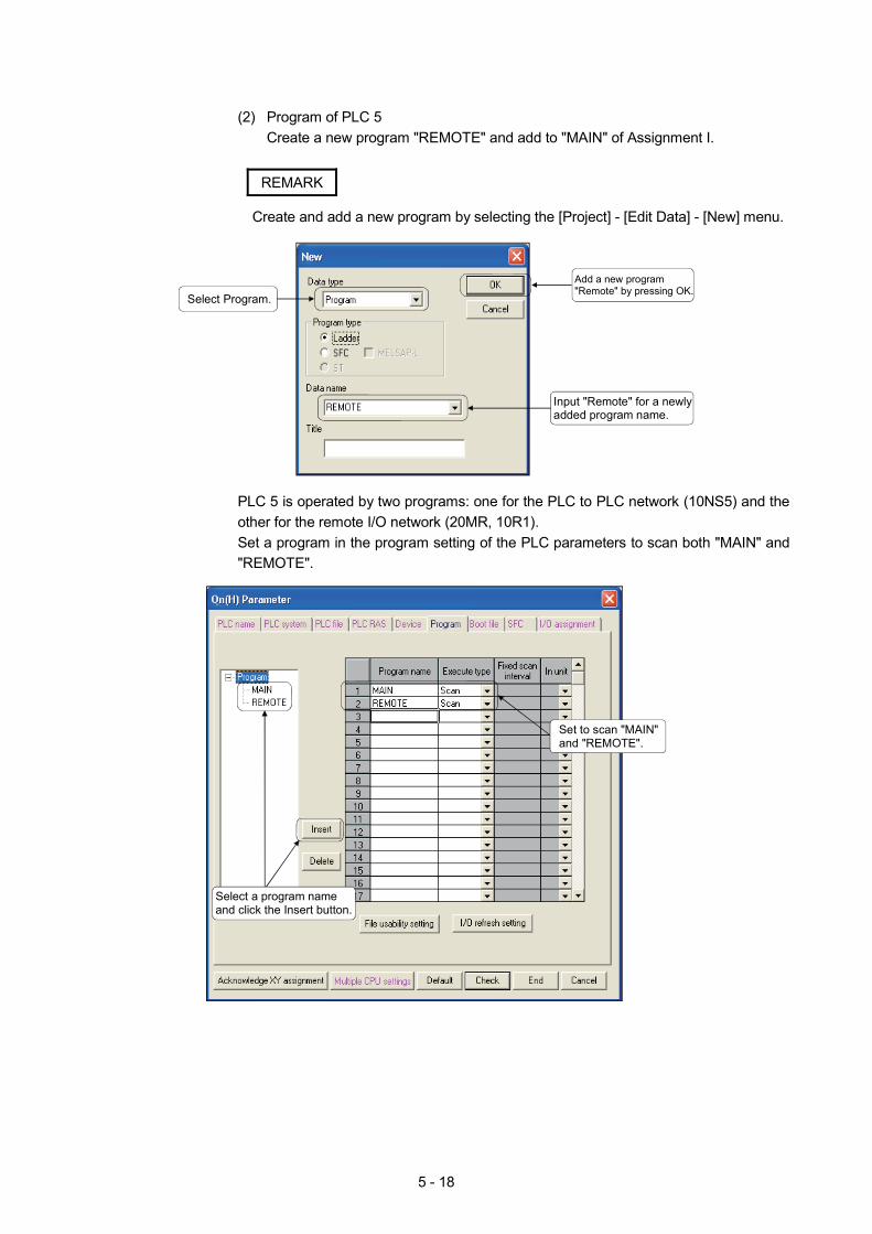
5 - 18
(2) Program of PLC 5
Create a new program "REMOTE" and add to "MAIN" of Assignment I.
REMARK
Create and add a new program by selecting the [Project] - [Edit Data] - [New] menu.
Add a new program"Remote" by pressing OK.
Input "Remote" for a newlyadded program name.
Select Program.
PLC 5 is operated by two programs: one for the PLC to PLC network (10NS5) and the other for the remote I/O network (20MR, 10R1). Set a program in the program setting of the PLC parameters to scan both "MAIN" and "REMOTE".
Set to scan "MAIN"and "REMOTE".
Select a program nameand click the Insert button.
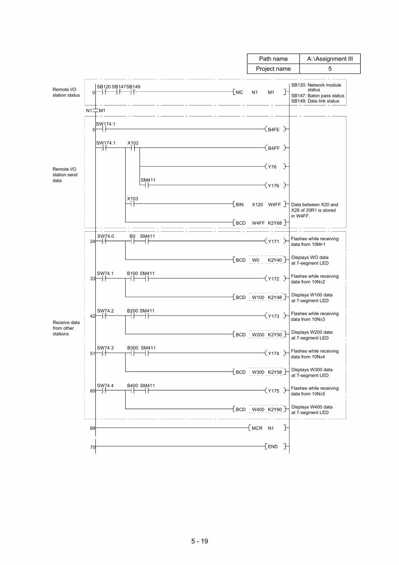
5 - 19
Path name A: Assignment III Project name 5
0SB120 SB147SB149
Receive data from other stations
N1 M1
SW174.15
B4FF
M1N1MC
Y76
SW74.0 B0 SM41124 Y171
SW74.1 B100 SM41133 Y172
SW74.2 B200 SM41142 Y173
SW74.3 B300 SM41151 Y174
W4FFX120BIN
K2Y68W4FFBCD
69 N1MCR
70 END
K2Y40W0BCD
K2Y48W100BCD
K2Y50W200BCD
K2Y58W300BCD
SW74.4 B400 SM41160 Y175
K2Y60W400BCD
B4FE
X103
SM411Y176
SB120: Network module statusSB147: Baton pass statusSB149: Data link status
Data between X20 and X28 of 20R1 is stored in W4FF.
Flashes while receiving data from 10MP1
Displays WO data at 7-segment LED
Flashes while receiving data from 10NS2
Displays W100 data at 7-segment LED
Flashes while receiving data from 10NS3
Displays W200 data at 7-segment LED
Flashes while receiving data from 10NS4
Displays W300 data at 7-segment LED
Flashes while receiving data from 10NS5
Displays W400 data at 7-segment LED
Remote I/O station send data
Remote I/O station status
X102SW174.1
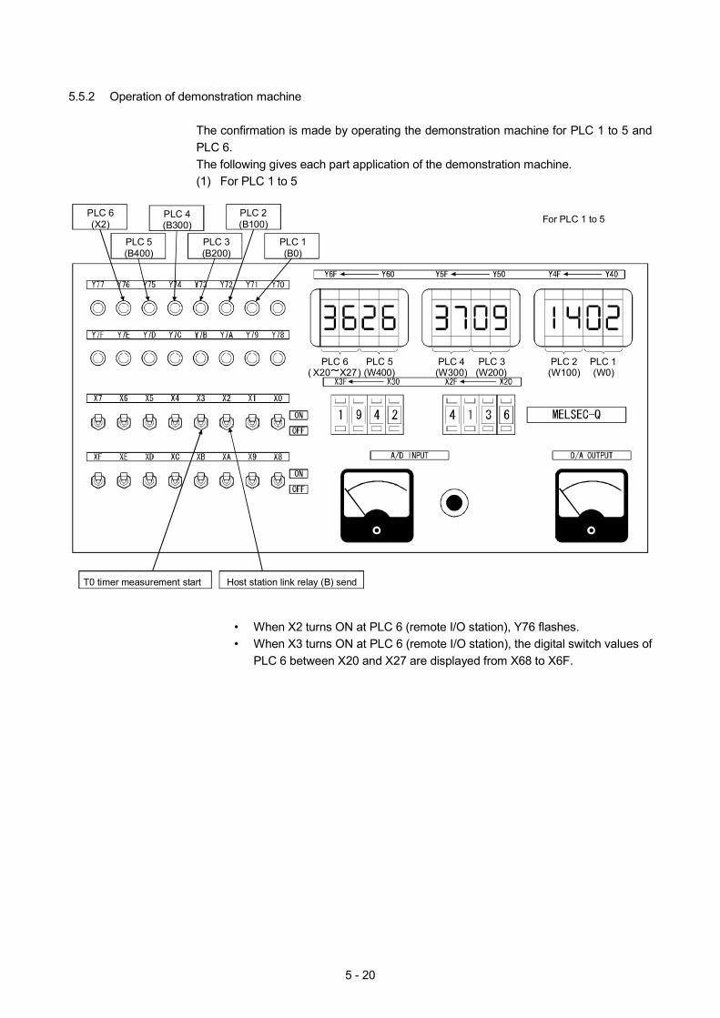
5 - 20
5.5.2 Operation of demonstration machine
The confirmation is made by operating the demonstration machine for PLC 1 to 5 and PLC 6. The following gives each part application of the demonstration machine. (1) For PLC 1 to 5
Host station link relay (B) sendT0 timer measurement start
(W400)PLC 4
(W300)PLC 3
(W200)PLC 2
(W100)PLC 1(W0)
PLC 1(B0)
PLC 6(X2)
PLC 5(B400)
PLC 3(B200)
PLC 2(B100)
PLC 4(B300) For PLC 1 to 5
( X20 X27)PLC 6 PLC 5
• When X2 turns ON at PLC 6 (remote I/O station), Y76 flashes. • When X3 turns ON at PLC 6 (remote I/O station), the digital switch values of
PLC 6 between X20 and X27 are displayed from X68 to X6F.
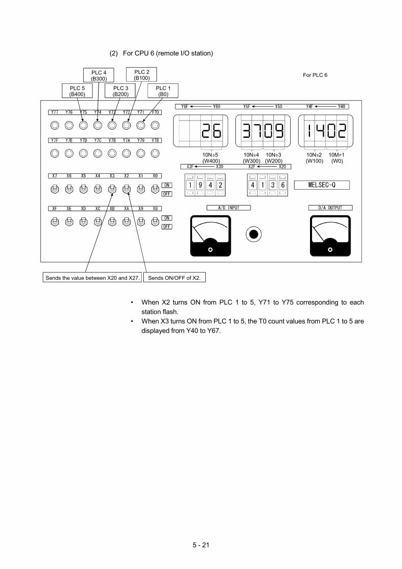
5 - 21
(2) For CPU 6 (remote I/O station)
Sends ON/OFF of X2.Sends the value between X20 and X27.
10NS5(W400)
10NS4(W300)
10NS3(W200)
10NS2(W100)
10MP1(W0)
PLC 1(B0)
PLC 5(B400)
PLC 3(B200)
PLC 2(B100)
PLC 4(B300)
For PLC 6
• When X2 turns ON from PLC 1 to 5, Y71 to Y75 corresponding to each
station flash. • When X3 turns ON from PLC 1 to 5, the T0 count values from PLC 1 to 5 are
displayed from Y40 to Y67.

5 - 22
MEMO
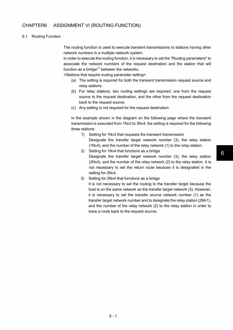
6 - 1
6
CHAPTER6 ASSIGNMENT VI (ROUTING FUNCTION)
6.1 Routing Function
The routing function is used to execute transient transmissions to stations having other network numbers in a multiple network system. In order to execute the routing function, it is necessary to set the "Routing parameters" to associate the network numbers of the request destination and the station that will function as a bridge*1 between the networks. <Stations that require routing parameter setting>
(a) The setting is required for both the transient transmission request source and relay stations.
(b) For relay stations, two routing settings are required: one from the request source to the request destination, and the other from the request destination back to the request source.
(c) Any setting is not required for the request destination.
In the example shown in the diagram on the following page where the transient transmission is executed from 1NS3 to 3NS4, the setting is required for the following three stations:
1) Setting for 1NS3 that requests the transient transmission Designate the transfer target network number (3), the relay station (1NS4), and the number of the relay network (1) to the relay station.
2) Setting for 1NS4 that functions as a bridge Designate the transfer target network number (3), the relay station (2NS4), and the number of the relay network (2) to the relay station. It is not necessary to set the return route because it is designated in the setting for 2NS4.
3) Setting for 2NS4 that functions as a bridge It is not necessary to set the routing to the transfer target because the host is on the same network as the transfer target network (3). However, it is necessary to set the transfer source network number (1) as the transfer target network number and to designate the relay station (2MP1), and the number of the relay network (2) to the relay station in order to trace a route back to the request source.
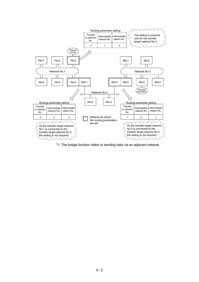
6 - 2
13
Intermediatenetwork No.
Transferto network
No.
Intermediatestation No.
4
23
Intermediatenetwork No.
Transferto network
No.
Intermediatestation No.
4 21
Intermediatenetwork No.
Transferto network
No.
Intermediatestation No.
1
Routing parameter setting
The setting is required only for the transfer target network No.3.
Routing parameter setting Routing parameter setting
Stations for whichthe routing parametersare set
Requestdestination
Requestsource
1MP1
1NS6
1NS2
1NS5
1NS3
1NS4 2MP1
Network No.1
3MP1
3NS5
3NS2
3NS4 3NS3
Network No.3
2NS4
2NS2 2NS3
Network No.2
*1: The bridge function refers to sending data via an adjacent network.
As the transfer target network No.1 is connected to the transfer target network No.2, the setting is not required.
As the transfer target network No.2 is connected to thetransfer target network No.3, the setting is not required.
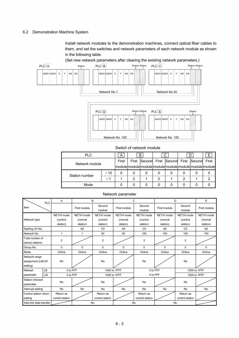
6 - 3
6.2 Demonstration Machine System
Install network modules to the demonstration machines, connect optical fiber cables to them, and set the switches and network parameters of each network module as shown in the following table. (Set new network parameters after clearing the existing network parameters.)
Network No.1 Network No.50
Network No. 150Network No. 100
X YX YX Y
Station1
Station2
Station1
Station2
Station1
Station2
Station2
Station1PLC A PLC B PLC C
PLC D PLC E
YX Y
Q02H AD DA AD DA AD DA
AD DAAD DA X
Q02H Q02HQ02H Q02HQ02H
Q02HQ02H Q02HQ02H
Switch of network module
PLC A B C D E
Network module First
moduleFirst
moduleSecond module
First module
Second module
First module
Second module
First module
10 0 0 0 0 0 0 0 0 Station number
1 1 2 1 2 1 2 1 2 Mode 0 0 0 0 0 0 0 0
Network parameter
A B C D E PLC
Item First module Second module
First module Second module
First module Second module
First module
Network type NET/H mode
(control station)
NET/H mode (normal station)
NET/H mode (control station)
NET/H mode (normal station)
NET/H mode (control station)
NET/H mode (normal station)
NET/H mode (control station)
NET/H mode(normal station)
Starting I/O No. A0 C0 A0 C0 A0 C0 A0
Network No. 1 1 50 50 100 100 150 150
Total number of (slave) stations
2 2 2 2
Group No. 0 0 0 0 0 0 0 0
Mode Online Online Online Online Online Online Online Online
Network range assignment (LB/LW setting)
No No No No
LB 0 to FFF 1000 to 1FFF 1000 to 1FFF Refresh parameter LW 0 to FFF 1000 to 1FFF
0 to FFF 0 to FFF 1000 to 1FFF
Station inherent parameter
No No No No
Interrupt setting No No No No No No No No
Control station return setting
Return as control station
Return as
control station
Return as control station
Return as
control station
Inter-link data transfer No No No
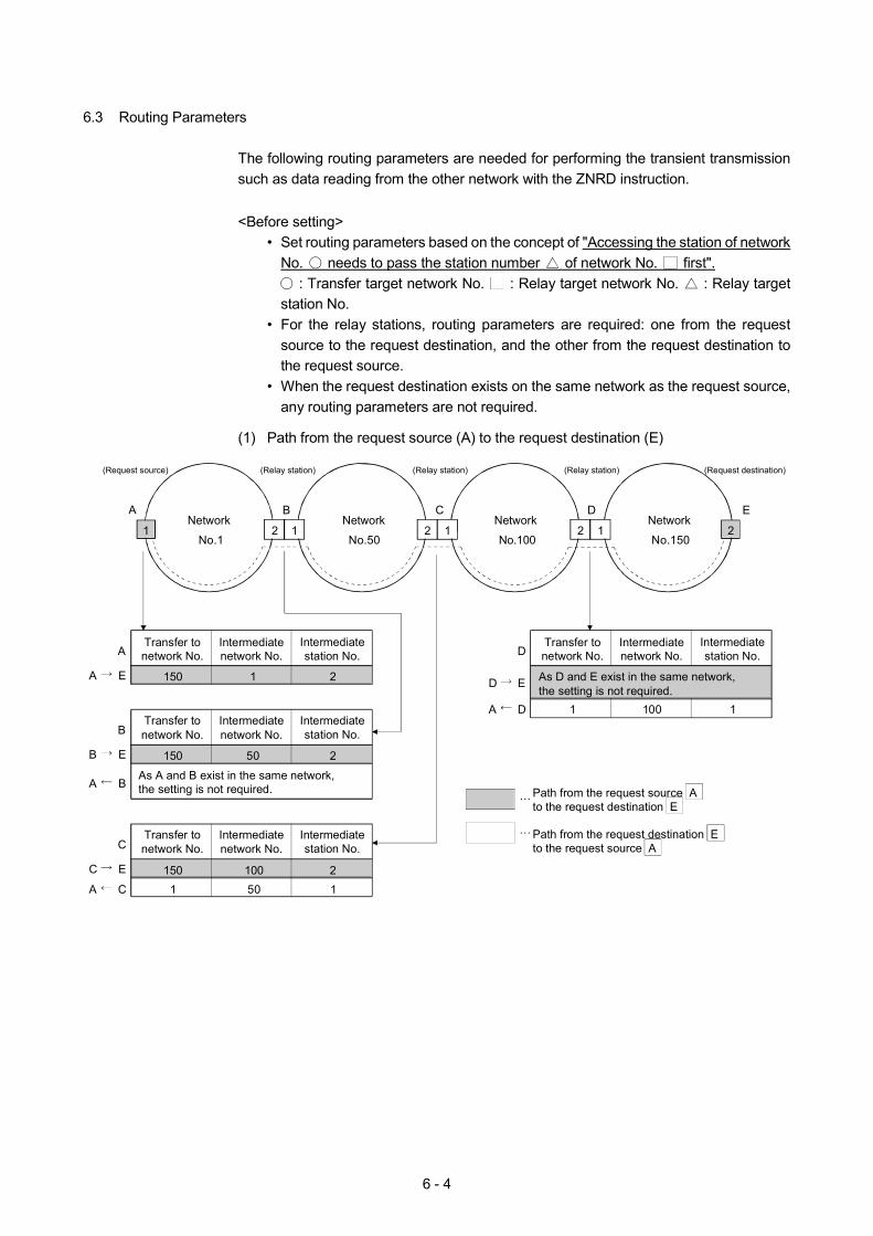
6 - 4
6.3 Routing Parameters
The following routing parameters are needed for performing the transient transmission such as data reading from the other network with the ZNRD instruction.
<Before setting>
• Set routing parameters based on the concept of "Accessing the station of network No. needs to pass the station number of network No. first".
: Transfer target network No. : Relay target network No. : Relay target station No.
• For the relay stations, routing parameters are required: one from the request source to the request destination, and the other from the request destination to the request source.
• When the request destination exists on the same network as the request source, any routing parameters are not required.
(1) Path from the request source (A) to the request destination (E)
(Request source)
A B C ENetwork
No.1
Network
No.50
Network
No.100
Network
No.1501 12 12 12 2
(Relay station) (Relay station) (Relay station) (Request destination)
Transfer tonetwork No.
Intermediatenetwork No.
Intermediatestation No.
Transfer tonetwork No.
Intermediatenetwork No.
Intermediatestation No.
Transfer tonetwork No.
Intermediatenetwork No.
Intermediatestation No.
Transfer tonetwork No.
Intermediatenetwork No.
Intermediatestation No.
150 1 2
A
A E
150 50 2
As A and B exist in the same network, the setting is not required.
B
B E
A B
150 100 2
C
C E
A C 1 50 1
As D and E exist in the same network, the setting is not required.
D
D E
1 100 1A D
Path from the request source A to the request destination E
Path from the request destination E to the request source A
D
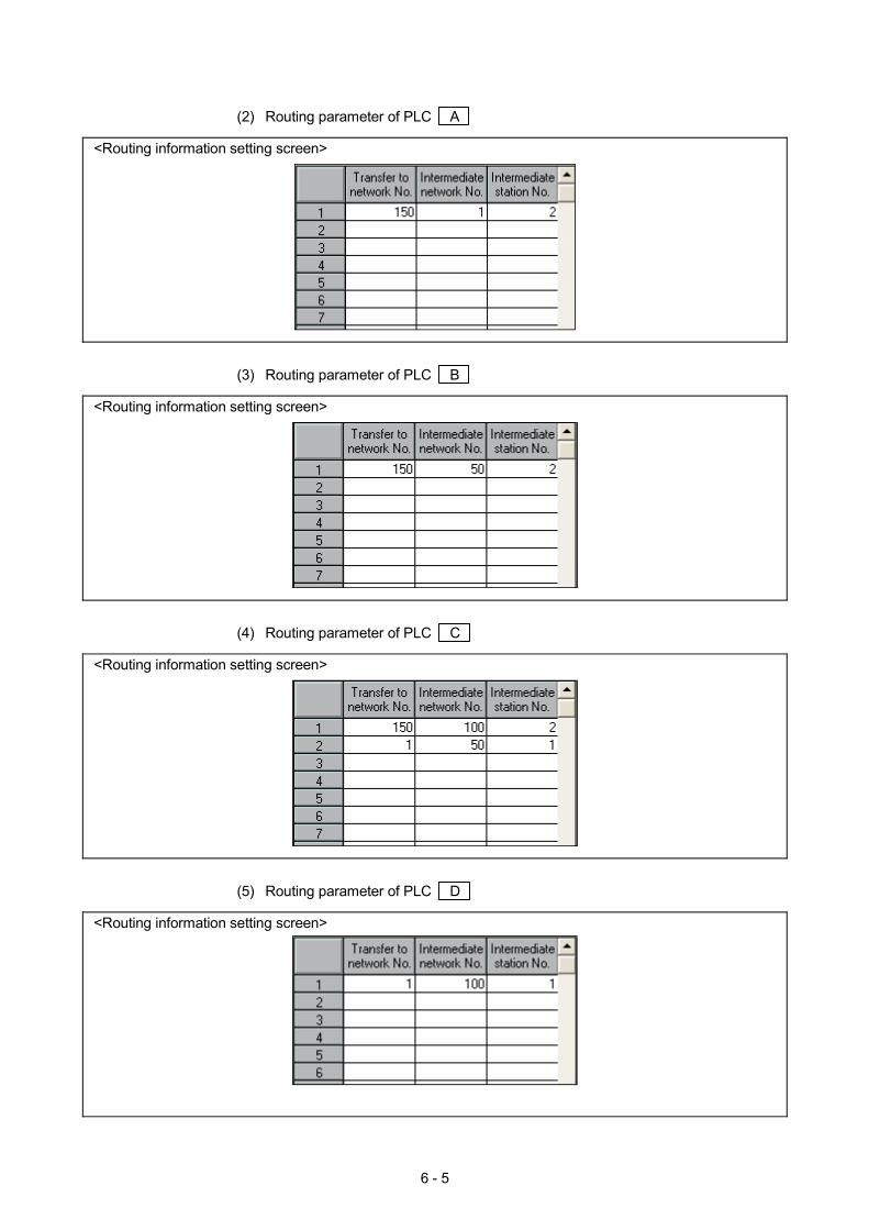
6 - 5
(2) Routing parameter of PLC A
<Routing information setting screen>
(3) Routing parameter of PLC B
<Routing information setting screen>
(4) Routing parameter of PLC C
<Routing information setting screen>
(5) Routing parameter of PLC D
<Routing information setting screen>
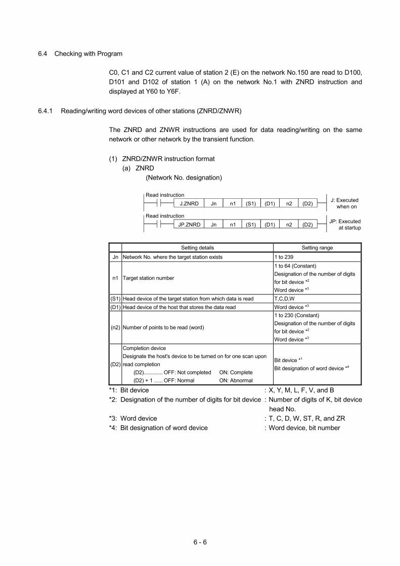
6 - 6
6.4 Checking with Program
C0, C1 and C2 current value of station 2 (E) on the network No.150 are read to D100, D101 and D102 of station 1 (A) on the network No.1 with ZNRD instruction and displayed at Y60 to Y6F.
6.4.1 Reading/writing word devices of other stations (ZNRD/ZNWR)
The ZNRD and ZNWR instructions are used for data reading/writing on the same network or other network by the transient function.
(1) ZNRD/ZNWR instruction format
(a) ZNRD (Network No. designation)
J.ZNRD J: Executed when on
Read instruction
JP.ZNRD JP: Executed at startup
Read instruction
Jn n1 n2
Jn n1 n2
(S1) (D1) (D2)
(S1) (D1) (D2)
Setting details Setting range
Jn Network No. where the target station exists 1 to 239
n1 Target station number
1 to 64 (Constant) Designation of the number of digits for bit device *2
Word device *3 (S1) Head device of the target station from which data is read T,C,D,W (D1) Head device of the host that stores the data read Word device *3
(n2) Number of points to be read (word)
1 to 230 (Constant) Designation of the number of digits for bit device *2 Word device *3
(D2)
Completion device Designate the host's device to be turned on for one scan upon read completion
(D2)............. OFF: Not completed ON: Complete (D2) + 1 ...... OFF: Normal ON: Abnormal
Bit device *1
Bit designation of word device *4
*1: Bit device : X, Y, M, L, F, V, and B *2: Designation of the number of digits for bit device : Number of digits of K, bit device
head No. *3: Word device : T, C, D, W, ST, R, and ZR *4: Bit designation of word device : Word device, bit number
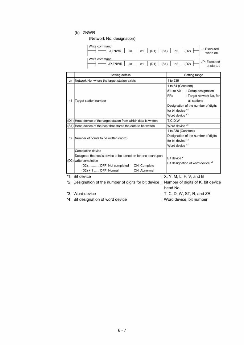
6 - 7
(b) ZNWR
(Network No. designation)
J.ZNWR J: Executed when on
Write command
JP.ZNWRJP: Executed at startup
Write command
Jn n1 n2
Jn n1 n2
(D1) (S1) (D2)
(D1) (S1) (D2)
Setting details Setting range
Jn Network No. where the target station exists 1 to 239
n1 Target station number
1 to 64 (Constant) 81H to A0H : Group designation FFH : Target network No, for
all stations Designation of the number of digits for bit device *2 Word device *3
(D1) Head device of the target station from which data is written T,C,D,W (S1) Head device of the host that stores the data to be written Word device *3
n2 Number of points to be written (word)
1 to 230 (Constant) Designation of the number of digits for bit device *2 Word device *3
(D2)
Completion device Designate the host's device to be turned on for one scan upon write completion
(D2)............. OFF: Not completed ON: Complete (D2) + 1 ...... OFF: Normal ON: Abnormal
Bit device *1 Bit designation of word device *4
*1: Bit device : X, Y, M, L, F, V, and B *2: Designation of the number of digits for bit device : Number of digits of K, bit device
head No. *3: Word device : T, C, D, W, ST, R, and ZR *4: Bit designation of word device : Word device, bit number
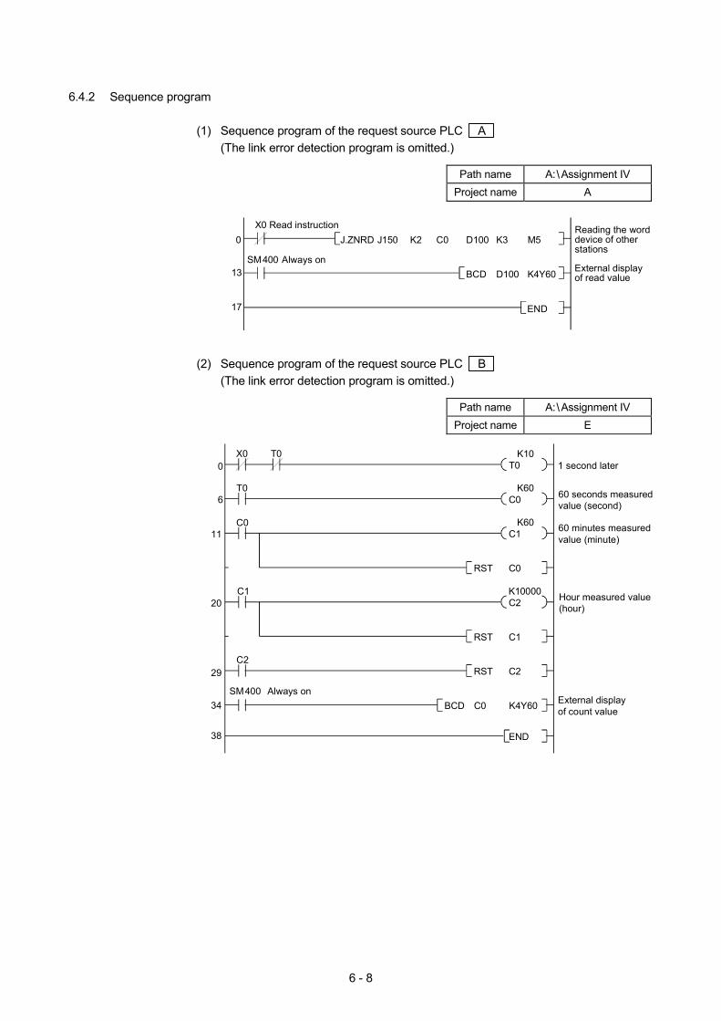
6 - 8
6.4.2 Sequence program
(1) Sequence program of the request source PLC A (The link error detection program is omitted.)
Path name A: Assignment IV
Project name A
K3C0X0 Read instruction
K4Y60D100 External display of read value
Reading the word device of other stations
END
D100K2J150J.ZNRD M5
BCD
0
13
17
SM400 Always on
(2) Sequence program of the request source PLC B
(The link error detection program is omitted.)
Path name A: Assignment IV Project name E
T0X0
1 second later
C0 60 seconds measuredvalue (second)
C1 60 minutes measuredvalue (minute)
C0RST
C2 Hour measured value(hour)
C1RST
C2RST
External display of count valueK4Y60
K60
K60
T0
T0
C0
C1
C2
SM400 Always onC0BCD
K10
K10000
0
6
34
29
20
11
38 END
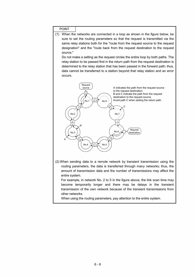
6 - 9
POINT (1) When the networks are connected in a loop as shown in the figure below, be
sure to set the routing parameters so that the request is transmitted via the same relay stations both for the "route from the request source to the request designation" and the "route back from the request destination to the request source." Do not make a setting as the request circles the entire loop by both paths. The relay station to be passed first in the return path from the request destination is determined to the relay station that has been passed in the forward path; thus, data cannot be transferred to a station beyond that relay station and an error occurs.
Requestsource
1
2 4
32
11
23
3 4
15
42
31
No.1 No.8
No.7
No.6Request
destination
No.5No.4
No.3
No.2
C
B
A
A indicates the path from the request source to the request destination.B and C indicate the path from the request destination to the request source.Avoid path C when setting the return path.
(2) When sending data to a remote network by transient transmission using the
routing parameters, the data is transferred through many networks; thus, the amount of transmission data and the number of transmissions may affect the entire system. For example, in network No. 2 to 5 in the figure above, the link scan time may become temporarily longer and there may be delays in the transient transmission of the own network because of the transient transmissions from other networks. When using the routing parameters, pay attention to the entire system.

6 - 10
MEMO
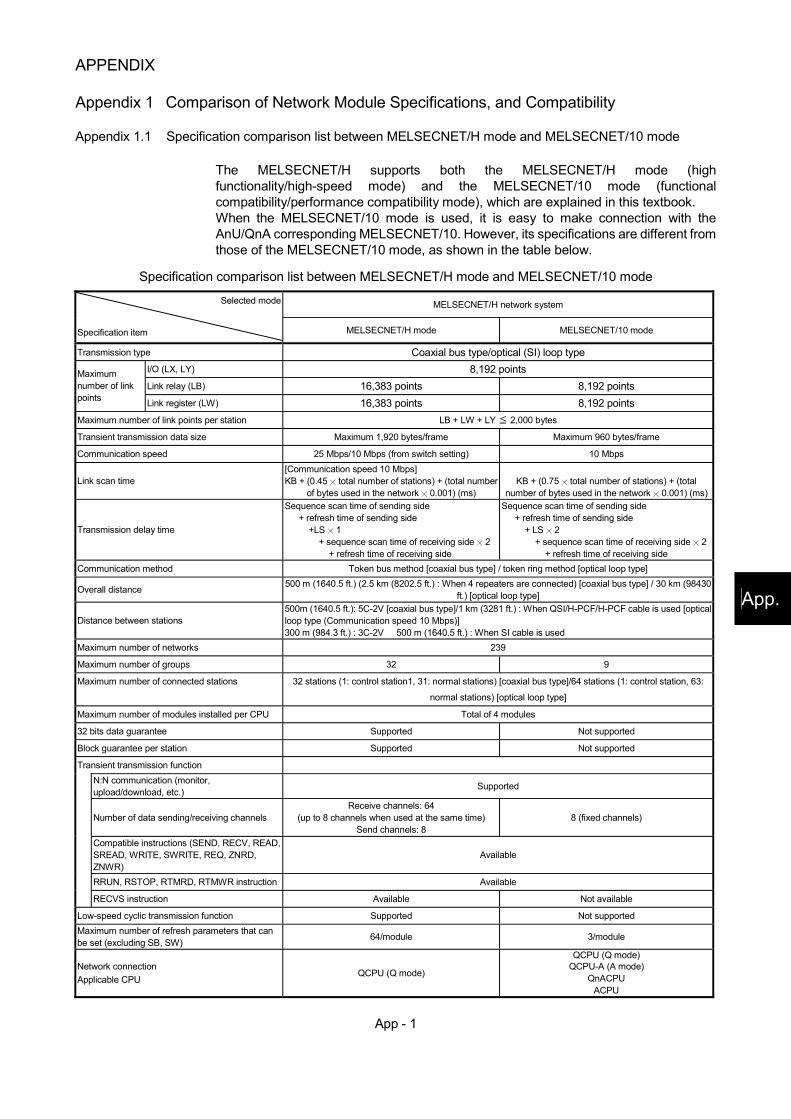
App - 1
App.
APPENDIX
Appendix 1 Comparison of Network Module Specifications, and Compatibility
Appendix 1.1 Specification comparison list between MELSECNET/H mode and MELSECNET/10 mode
The MELSECNET/H supports both the MELSECNET/H mode (high functionality/high-speed mode) and the MELSECNET/10 mode (functional compatibility/performance compatibility mode), which are explained in this textbook. When the MELSECNET/10 mode is used, it is easy to make connection with the AnU/QnA corresponding MELSECNET/10. However, its specifications are different from those of the MELSECNET/10 mode, as shown in the table below.
Specification comparison list between MELSECNET/H mode and MELSECNET/10 mode
MELSECNET/H network system Selected mode
Specification item MELSECNET/H mode MELSECNET/10 mode
Transmission type Coaxial bus type/optical (SI) loop type I/O (LX, LY) 8,192 points Link relay (LB) 16,383 points 8,192 points
Maximum number of link points Link register (LW) 16,383 points 8,192 points Maximum number of link points per station LB + LW + LY 2,000 bytes
Transient transmission data size Maximum 1,920 bytes/frame Maximum 960 bytes/frame
Communication speed 25 Mbps/10 Mbps (from switch setting) 10 Mbps
Link scan time [Communication speed 10 Mbps] KB + (0.45 total number of stations) + (total number
of bytes used in the network 0.001) (ms)
KB + (0.75 total number of stations) + (total
number of bytes used in the network 0.001) (ms)
Transmission delay time
Sequence scan time of sending side + refresh time of sending side
+LS 1 + sequence scan time of receiving side 2
+ refresh time of receiving side
Sequence scan time of sending side + refresh time of sending side
+ LS 2 + sequence scan time of receiving side 2
+ refresh time of receiving side Communication method Token bus method [coaxial bus type] / token ring method [optical loop type]
Overall distance 500 m (1640.5 ft.) (2.5 km (8202.5 ft.) : When 4 repeaters are connected) [coaxial bus type] / 30 km (98430 ft.) [optical loop type]
Distance between stations 500m (1640.5 ft.): 5C-2V [coaxial bus type]/1 km (3281 ft.) : When QSI/H-PCF/H-PCF cable is used [optical loop type (Communication speed 10 Mbps)] 300 m (984.3 ft.) : 3C-2V 500 m (1640.5 ft.) : When SI cable is used
Maximum number of networks 239
Maximum number of groups 32 9
Maximum number of connected stations 32 stations (1: control station1, 31: normal stations) [coaxial bus type]/64 stations (1: control station, 63:
normal stations) [optical loop type]
Maximum number of modules installed per CPU Total of 4 modules
32 bits data guarantee Supported Not supported
Block guarantee per station Supported Not supported
Transient transmission function
N:N communication (monitor, upload/download, etc.) Supported
Number of data sending/receiving channels
Receive channels: 64 (up to 8 channels when used at the same time)
Send channels: 8 8 (fixed channels)
Compatible instructions (SEND, RECV, READ, SREAD, WRITE, SWRITE, REQ, ZNRD, ZNWR)
Available
RRUN, RSTOP, RTMRD, RTMWR instruction Available
RECVS instruction Available Not available
Low-speed cyclic transmission function Supported Not supported Maximum number of refresh parameters that can be set (excluding SB, SW) 64/module 3/module
Network connection Applicable CPU
QCPU (Q mode)
QCPU (Q mode) QCPU-A (A mode)
QnACPU ACPU
App - 2
Appendix 1.2 Compatibility between the function version B and the function version A
The following explains the compatibility between the function version B and the function version A of the network module QJ71LP21(-25)/QJ71BR11 on PLC to PLC network.
The function version B is compatible within the range of the function version A. When replacing the network module from the function version A to the function version B, it is not required to change the settings for parameters, programs and switches.
The function version B has the following functions that are changed or added after the function version A. 1) Multiple CPU systems are supported 2) The dedicated link instructions are added (4 instructions) 3) The data length of the dedicated link instruction is changed (480 words to 960 words)
REMARK
The function version A of QJ71LP21/QJ71BR11 cannot be used for the remote master station of the remote I/O network.
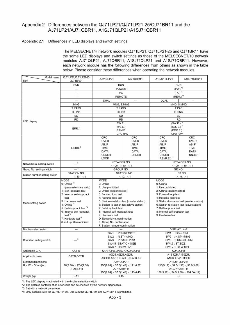
App - 3
Appendix 2 Differences between the QJ71LP21/QJ71LP21-25/QJ71BR11 and the
AJ71LP21/AJ71QBR11, A1SJ71QLP21/A1SJ71QBR11
Appendix 2.1 Differences in LED displays and switch settings
The MELSECNET/H network modules QJ71LP21, QJ71LP21-25 and QJ71BR11 have the same LED displays and switch settings as those of the MELSECNET/10 network modules AJ71QLP21, AJ71QBR11, A1SJ71QLP21 and A1SJ71QBR11. However, each network module has the following differences from others as shown in the table below. Please consider these differences when operating the network modules.
Model name
Item QJ71LP21, QJ71LP21-25
QJ71BR21 AJ71QLP21 AJ71QBR11 A1SJ71QLP21 A1SJ71QBR11
RUN RUN RUN — POWER (PW) *1 — PC (PC) *1 — REMOTE (REM.) *1 — DUAL — DUAL —
MNG MNG, S.MNG MNG, S.MNG T.PASS T.PASS T.PAS D.LINK D.LINK D.LINK
SD SD SD RD RD RD
ERR.*2
SW.E. M/S.E. PRM.E. CPU R/W
(SW.E.) *1 (M/S.E.) *1 (PRM.E.) *1 CPU R/W
LED display
L ERR.*2
CRC OVER AB.IF TIME DATA UNDER LOOP
CRC OVER AB.IF TIME DATA UNDER
CRC OVER AB.IF TIME DATA UNDER F.E.(R.E.) *1
CRC OVER AB.IF TIME DATA UNDER
Network No. setting switch —*3 NETWORK NO. 100, 10, 1
NETWORK NO. 100, 10, 1
Group No. setting switch —*3 GROUP NO. GR.NO.
Station number setting switch STATION NO. 10, 1
STATION NO. 10, 1
ST.NO. 10, 1
Mode setting switch
MODE 0: Online *3
(parameters are valid) 1: Self-loopback test 2: Internal self-loopback
test 3: Hardware test 4: Online *4 5: Self-loopback test *4 6: Internal self-loopback
test *4 7: Hardware test *4
8 and up: Use rohibited
MODE 0: Online 1: Use prohibited 2: Offline (disconnected) 3: Forward loop test 4: Reverse loop test 5: Station-to-station test (master station) 6: Station-to-station test (slave station) 7: Self-loopback test 8: Internal self-loopback test 9: Hardware test D: Network No. confirmation E: Group No. confirmation F: Station number confirmation
MODE 0: Online 1: Use prohibited 2: Offline (disconnected) 3: Forward loop test 4: Reverse loop test 5: Station-to-station test (master station) 6: Station-to-station test (slave station) 7: Self-loopback test 8: Internal self-loopback test 9: Hardware test
Display select switch — — DISPLAY L R
Condition setting switch —*3
SW1 : PC REMOTE SW2 : N.ST MNG SW3 : PRM D.PRM SW4,5 : STATION SIZE SW6,7 : LB/LW SIZE
SW1 : PC REM SW2 : N.ST MNG SW3 : PRM D.PRM SW4,5 : ST.SIZE SW6,7 : LB/LW SIZE
Applicable CPU QCPU Q4ARCPU,QnACPU,Q2ASCPU Q2ASCPU
Applicable base Q3 B,Q6 B A3 B,A5 B,A6 B, A38HB,A37RHB,A3 RB,A68RB
A1S3 B,A1S5 B, A1S6 B,A1S38HB
External dimensions H W D(mm(in.)) 98(3.86) 27.4(1.08)
90(3.54)
AJ71QLP21: 250(9.84) 37.5(1.48) 111(4.37)
AJ71QBR11: 250(9.84) 37.5(1.48) 113(4.45)
A1SJ71QLP21: 130(5.12) 34.5(1.36) 93.6(3.69)
A1SJ71QBR11: 130(5.12) 34.5(1.36) 104.6(4.12)
Weight (kg) 0.11 0.45 0.3 *1: The LED display is activated with the display selection switch. *2: The detailed contents of an error code can be checked by the network diagnostics. *3: Set with a network parameter. *4: Only possible with the QJ71LP21-25. Use with the QJ71LP21 and QJ71BR11 is prohibited.
App - 4
Appendix 2.2 Precautions when replacing the AJ71QLP21/AJ71QBR11 and the
A1SJ71QLP21/A1SJ71QBR11 with the QJ71LP21/QJ71LP21-25/QJ71BR11
The following are the precautions when replacing the QnACPU MELSECNET/10 network system with the QCPU MELSECNET/H network system:
(1) Switch settings of the network module
The MELSECNET/H network module does not have a network number setting switch, a group number setting switch and a condition setting switch (default parameter setting) of the MELSECNET/10 network module. Thus, these switches must be set with the network parameters.
(2) Correcting the network parameters
The corrections as described in item (1) above are required for the network parameters. In particular, when the default parameters are set in SW3 of the network module, there will be no parameter information about the network after converting from QnA to Q with GX Developer. When the default parameter is used, make sure to set the network parameters with GX Developer after the conversion.
(3) Correcting the sequence programs
It is not necessary to correct the sequence programs, such as the interlock program that use a link special relay or a link special register and the program for accessing other stations using the data link instructions. • The operations of the link special relays and link special registers used in the
MELSECNET/10 network are the same as those in the MELSECNET/H. • The interlock link special relay is required to use the data link instruction in the
MELSECNET/10 network, however, it is not required for the MELSECNET/H network. In addition, the sequence program will operate normally even if the interlock link special relay remains in the sequence program after conversion.
(4) Distance between optical fiber cable stations
The distance between stations will become shorter when changing network systems to a communication speed of 25Mbps depending on the optical fiber cable in use. In this event, set the communication speed to 10Mbps, or rewire the system with different optical fiber cables.
App - 5
Appendix 2.3 Precautions when changing over from the MELSECNET/10 remote I/O network to the
MELSECNET/H remote I/O network.
The following describes the precautions to take when switching from the AnUCPU, QnACPU MELSECNET/10 remote I/O network to the QCPU MELSECNET/H remote I/O network. (1) Cannot be mixed with other network modules.
The MELSECNET/10 network modules and MELSECNET/H network modules cannot be mixed. • The MELSECNET/H remote I/O modules cannot be connected to the
MELSECNET/10 master modules. • The MELSECNET/10 remote I/O modules cannot be connected to the
MELSECNET/H master modules. When changing remote I/O modules, use MELSECNET/H for all network modules.
(2) Switch settings of the network module
The network number setting switches and condition setting switches for the MELSECNET/10 network modules are not found on the MELSECNET/H network module. These settings must be made by the network parameters.
(3) Correction of remote master station network parameters
The network parameters for the remote master station require the corrections shown in (2) above.
(4) Setting of parameters to remote I/O station
• The I/O assignment settings set by the network parameters of the MELSECNET/10 remote I/O network master module are set by the remote I/O module PLC parameters on the MELSECNET/H remote I/O network.
• When changing the intelligent function modules mounted to the remote I/O station, it is necessary to make switch settings using the remote I/O station PLC parameters depending on model. For details, refer to the User's Manual for the intelligent function module being used.
(5) Correcting the sequence programs
It is not necessary to correct the sequence programs, such as the interlock program that use a link special relay or a link special register and the program for accessing other stations using the data link instructions. However, the data link instructions (ZNFR/ZNTO instructions) used for accessing the buffer memory of the intelligent function module of the remote I/O station and the data link instructions (ZNRD/ZNWR instructions) used for reading/writing of the other station word device cannot be used on the MELSECNET/H remote I/O network. Accordingly, on the MELSECNET/H, rewrite the ZNFR/ZNTO instructions to REMFR/REMTO instructions and the ZNRD/ZNWR instructions to READ/WRITE instructions. • The link special relays and link special register operations used in the
MELSECNET/10 remote I/O network are the same as that in the MELSECNET/H network.
(6) Distance between optical fiber cable stations
When the remote I/O network speed is changed to 25 Mbps depending on the optical fiber cable, the distance between stations will become shorter. In this event, set the communication speed to 10Mbps, or rewire the system with different optical fiber cables.
(7) The multiplex master and parallel master functions cannot be used since they are
not supported.
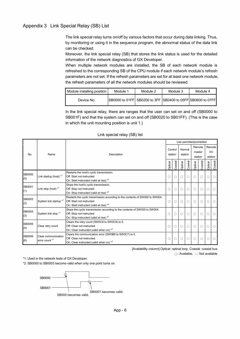
App - 6
Appendix 3 Link Special Relay (SB) List
The link special relay turns on/off by various factors that occur during data linking. Thus, by monitoring or using it in the sequence program, the abnormal status of the data link can be checked. Moreover, the link special relay (SB) that stores the link status is used for the detailed information of the network diagnostics of GX Developer. When multiple network modules are installed, the SB of each network module is refreshed to the corresponding SB of the CPU module if each network module’s refresh parameters are not set. If the refresh parameters are set for at least one network module, the refresh parameters of all the network modules should be reviewed.
Module installing position Module 1 Module 2 Module 3 Module 4
Device No. SB0000 to 01FF SB0200 to 3FF SB0400 to 05FF SB0600 to 07FF
In the link special relay, there are ranges that the user can set on and off (SB0000 to SB001F) and that the system can set on and off (SB0020 to SB01FF). (This is the case in which the unit mounting position is unit 1.)
Link special relay (SB) list
Use permitted/prohibited
Control
station
Normal
station
Remote
master
station
Remote
I/O
station No. Name Description
Opt
ical
Coa
xial
Opt
ical
Coa
xial
Opt
ical
Coa
xial
Opt
ical
Coa
xial
SB0000 (0)
Link startup (host) *1 Restarts the host's cyclic transmission. Off: Start not instructed On: Start instructed (valid at rise) *2
SB0001 (1)
Link stop (host) *1 Stops the host's cyclic transmission. Off: Stop not instructed On: Stop instructed (valid at rise) *2
SB0002 (2)
System link startup *1 Restarts the cyclic transmission according to the contents of SW000 to SW004. Off: Start not instructed On: Start instructed (valid at rise) *2
SB0003 (3)
System link stop *1 Stops the cyclic transmission according to the contents of SW000 to SW004. Off: Stop not instructed On: Stop instructed (valid at rise) *2
SB0005 (5)
Clear retry count Clears the retry count (SW0C8 to SW0C9) to 0. Off: Clear not instructed On: Clear instructed (valid when on) *2
SB0006 (6)
Clear communication error count *1
Clears the communication error (SW0B8 to SW0C7) to 0. Off: Clear not instructed On: Clear instructed (valid when on) *2
[Availability column] Optical: optical loop, Coaxial: coaxial bus
: Available, : Not available *1: Used in the network tests of GX Developer. *2: SB0000 to SB0003 become valid when only one point turns on.
SB000 becomes valid.SB0001 becomes valid.
SB0001
SB0000
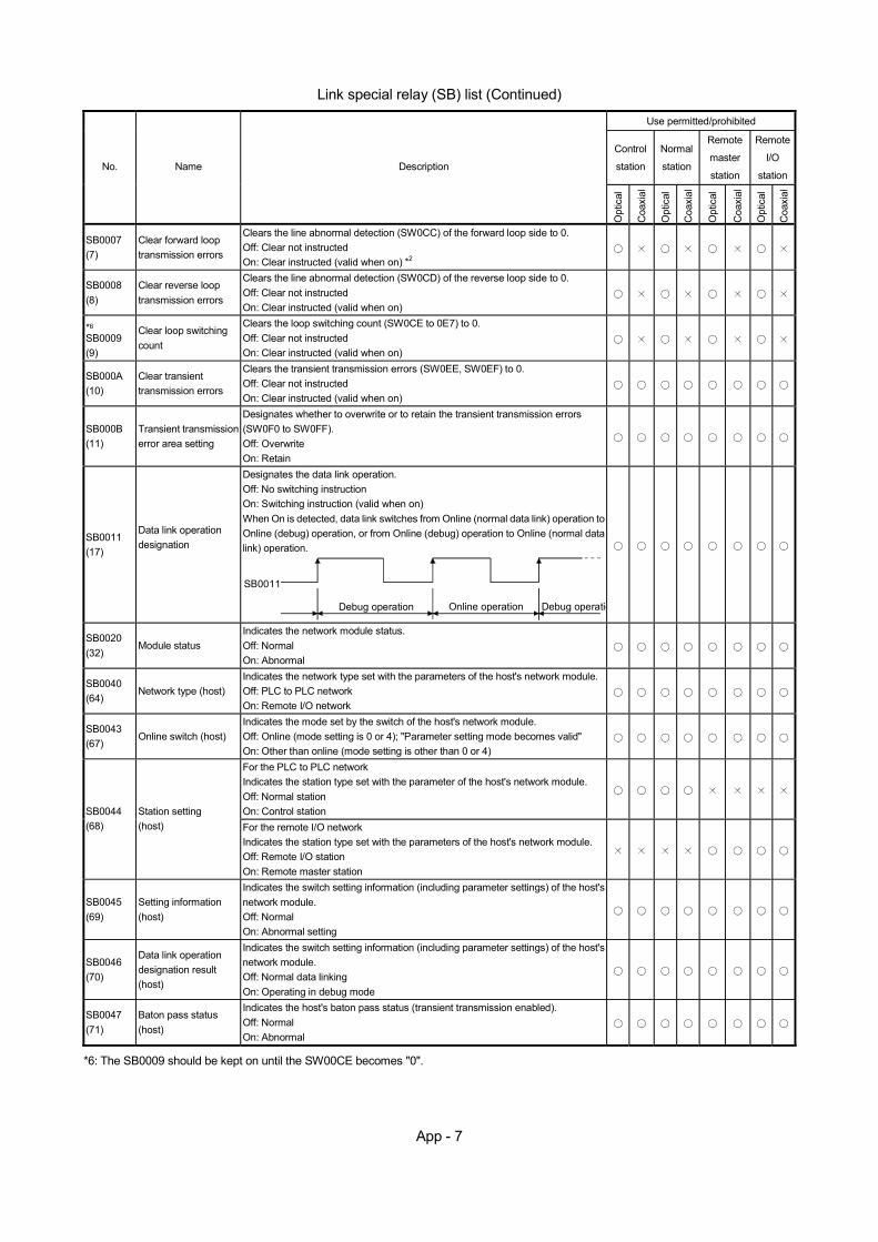
App - 7
Link special relay (SB) list (Continued)
Use permitted/prohibited
Control
station
Normal
station
Remote
master
station
Remote
I/O
station No. Name Description
Opt
ical
Coa
xial
Opt
ical
Coa
xial
Opt
ical
Coa
xial
Opt
ical
Coa
xial
SB0007 (7)
Clear forward loop transmission errors
Clears the line abnormal detection (SW0CC) of the forward loop side to 0. Off: Clear not instructed On: Clear instructed (valid when on) *2
SB0008 (8)
Clear reverse loop transmission errors
Clears the line abnormal detection (SW0CD) of the reverse loop side to 0. Off: Clear not instructed On: Clear instructed (valid when on)
*6 SB0009 (9)
Clear loop switching count
Clears the loop switching count (SW0CE to 0E7) to 0. Off: Clear not instructed On: Clear instructed (valid when on)
SB000A (10)
Clear transient transmission errors
Clears the transient transmission errors (SW0EE, SW0EF) to 0. Off: Clear not instructed On: Clear instructed (valid when on)
SB000B (11)
Transient transmission error area setting
Designates whether to overwrite or to retain the transient transmission errors (SW0F0 to SW0FF). Off: Overwrite On: Retain
SB0011 (17)
Data link operation designation
Designates the data link operation. Off: No switching instruction On: Switching instruction (valid when on) When On is detected, data link switches from Online (normal data link) operation to Online (debug) operation, or from Online (debug) operation to Online (normal data link) operation.
Debug operation Online operation
SB0011
Debug operatio
SB0020 (32)
Module status Indicates the network module status. Off: Normal On: Abnormal
SB0040 (64)
Network type (host) Indicates the network type set with the parameters of the host's network module. Off: PLC to PLC network On: Remote I/O network
SB0043 (67)
Online switch (host) Indicates the mode set by the switch of the host's network module. Off: Online (mode setting is 0 or 4); "Parameter setting mode becomes valid" On: Other than online (mode setting is other than 0 or 4)
For the PLC to PLC network Indicates the station type set with the parameter of the host's network module. Off: Normal station On: Control station
SB0044 (68)
Station setting (host) For the remote I/O network
Indicates the station type set with the parameters of the host's network module. Off: Remote I/O station On: Remote master station
SB0045 (69)
Setting information (host)
Indicates the switch setting information (including parameter settings) of the host's network module. Off: Normal On: Abnormal setting
SB0046 (70)
Data link operation designation result (host)
Indicates the switch setting information (including parameter settings) of the host's network module. Off: Normal data linking On: Operating in debug mode
SB0047 (71)
Baton pass status (host)
Indicates the host's baton pass status (transient transmission enabled). Off: Normal On: Abnormal
*6: The SB0009 should be kept on until the SW00CE becomes "0".

App - 8
Link special relay (SB) list (Continued)
Use permitted/prohibited
Control
station
Normal
station
Remote
master
station
Remote
I/O
station No. Name Description
Opt
ical
Coa
xial
Opt
ical
Coa
xial
Opt
ical
Coa
xial
Opt
ical
Coa
xial
Control station status (host)
For the PLC to PLC network Indicates the host's status. (Valid when SB0047 is off.) Off: Normal station On: Control station (SB0044 is on) Sub-control station (SB0044 is off)
*3 SB0048 (72)
Remote master station status (host)
For the remote I/O network Indicates the host's status. (Valid when SB0047 is off.) Off: Remote I/O station On: Remote master station
*3 SB0049 (73)
Host data link status Indicates the host's data link operation status. Off: Normal On: Abnormal (Set after refreshing completes.)
*3*4 SB004A (74)
Host CPU status (1) Indicates the host's CPU status. Off: Normal On: Minor error occurred
— —
*3*5
SB004B (75)
Host CPU status (2) Indicates the host's CPU status. Off: Normal On: Serious or fatal error occurred
— —
*3
SB004C (76)
Cyclic transmission start acknowledgment status
Indicates the startup acknowledgment status of the cyclic transmission. Off: Not acknowledged (SB0000 is off) On: Stop acknowledged (SB0000 is on)
*3
SB004D (77)
Cyclic transmission start completion status
Indicates the completion status of the cyclic transmission. Off: Not completed (SB0000 is off) On: Start completed (SB0000 is on)
*3
SB004E (78)
Cyclic transmission stop acknowledgment status
Indicates the stop acknowledgment status of the cyclic transmission. Off: Not acknowledged (SB0001 is off) On: Stop acknowledged (SB0001 is on)
*3
SB004F (79)
Cyclic transmission stop completion status
Indicates the stop completion status of the cyclic transmission. Off: Not completed (SB0001 is off) On: Stop completed (SB0001 is on)
*3 SB0050 (80)
Cyclic transmission start acknowledgment status
Indicates the startup acknowledgment status of the cyclic transmission. Off: Not acknowledged (SB0002 is off) On: Start acknowledged (SB0002 is on)
*3 SB0051 (81)
Cyclic transmission start completion status
Indicates the completion status of the cyclic transmission. Off: Not completed (SB0002 is off) On: Start completed (SB0002 is on)
*3 SB0052 (82)
Cyclic transmission stop acknowledgment status
Indicates the stop acknowledgment status of the cyclic transmission. Off: Not acknowledged (SB0003 is off) On: Start acknowledged (SB0003 is on)
*3 SB0053 (83)
Cyclic transmission stop completion status
Indicates the stop completion status of the cyclic transmission. Off: Not completed (SB0003 is off) On: Stop completed (SB0003 is on)
*3 SB0054 (84)
Parameter receive status
Indicates the parameter receive status. Off: Receive completed On: Not received
*3 SB0055 (85)
Received parameter error
Indicates the status of the received parameters. Off: Parameters normal On: Parameters abnormal
*3: Valid only when SB0047 is off. When it turns on (error), the last data are retained. *4: Minor errors (battery error, etc.) are the type of errors that do not affect the CPU operation. *5: Serious errors (WDT error, etc.) are the type of errors that stop the CPU operation.
Fatal errors (RAM error, etc.) are also the type of errors that stop the CPU operation. (Error code: 11 )
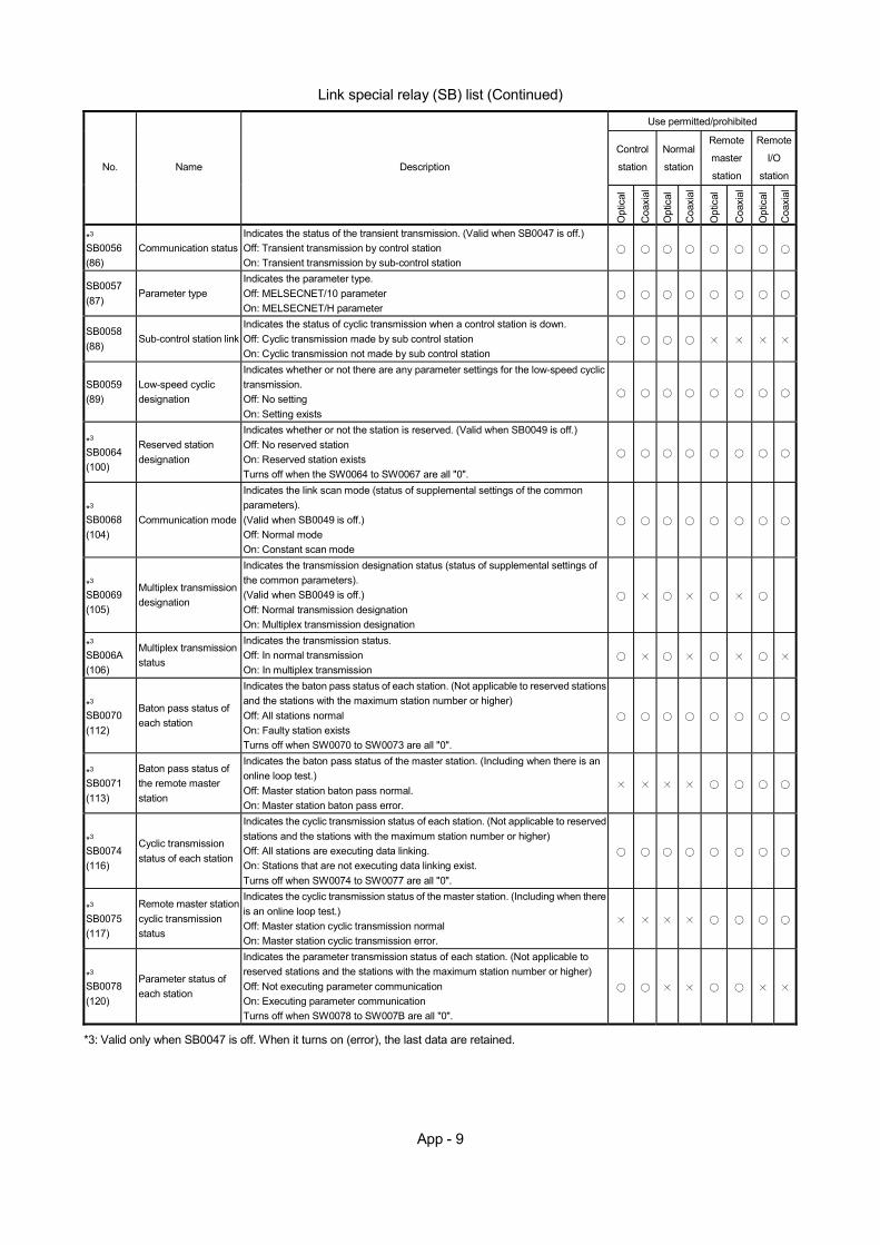
App - 9
Link special relay (SB) list (Continued)
Use permitted/prohibited
Control
station
Normal
station
Remote
master
station
Remote
I/O
station No. Name Description
Opt
ical
Coa
xial
Opt
ical
Coa
xial
Opt
ical
Coa
xial
Opt
ical
Coa
xial
*3 SB0056 (86)
Communication status Indicates the status of the transient transmission. (Valid when SB0047 is off.) Off: Transient transmission by control station On: Transient transmission by sub-control station
SB0057 (87)
Parameter type Indicates the parameter type. Off: MELSECNET/10 parameter On: MELSECNET/H parameter
SB0058 (88)
Sub-control station link Indicates the status of cyclic transmission when a control station is down. Off: Cyclic transmission made by sub control station On: Cyclic transmission not made by sub control station
SB0059 (89)
Low-speed cyclic designation
Indicates whether or not there are any parameter settings for the low-speed cyclic transmission. Off: No setting On: Setting exists
*3
SB0064 (100)
Reserved station designation
Indicates whether or not the station is reserved. (Valid when SB0049 is off.) Off: No reserved station On: Reserved station exists Turns off when the SW0064 to SW0067 are all "0".
*3
SB0068 (104)
Communication mode
Indicates the link scan mode (status of supplemental settings of the common parameters). (Valid when SB0049 is off.) Off: Normal mode On: Constant scan mode
*3
SB0069 (105)
Multiplex transmission designation
Indicates the transmission designation status (status of supplemental settings of the common parameters). (Valid when SB0049 is off.) Off: Normal transmission designation On: Multiplex transmission designation
*3
SB006A (106)
Multiplex transmission status
Indicates the transmission status. Off: In normal transmission On: In multiplex transmission
*3 SB0070 (112)
Baton pass status of each station
Indicates the baton pass status of each station. (Not applicable to reserved stations and the stations with the maximum station number or higher) Off: All stations normal On: Faulty station exists Turns off when SW0070 to SW0073 are all "0".
*3 SB0071 (113)
Baton pass status of the remote master station
Indicates the baton pass status of the master station. (Including when there is an online loop test.) Off: Master station baton pass normal. On: Master station baton pass error.
*3 SB0074 (116)
Cyclic transmission status of each station
Indicates the cyclic transmission status of each station. (Not applicable to reserved stations and the stations with the maximum station number or higher) Off: All stations are executing data linking. On: Stations that are not executing data linking exist. Turns off when SW0074 to SW0077 are all "0".
*3 SB0075 (117)
Remote master station cyclic transmission status
Indicates the cyclic transmission status of the master station. (Including when there is an online loop test.) Off: Master station cyclic transmission normal On: Master station cyclic transmission error.
*3 SB0078 (120)
Parameter status of each station
Indicates the parameter transmission status of each station. (Not applicable to reserved stations and the stations with the maximum station number or higher) Off: Not executing parameter communication On: Executing parameter communication Turns off when SW0078 to SW007B are all "0".
*3: Valid only when SB0047 is off. When it turns on (error), the last data are retained.
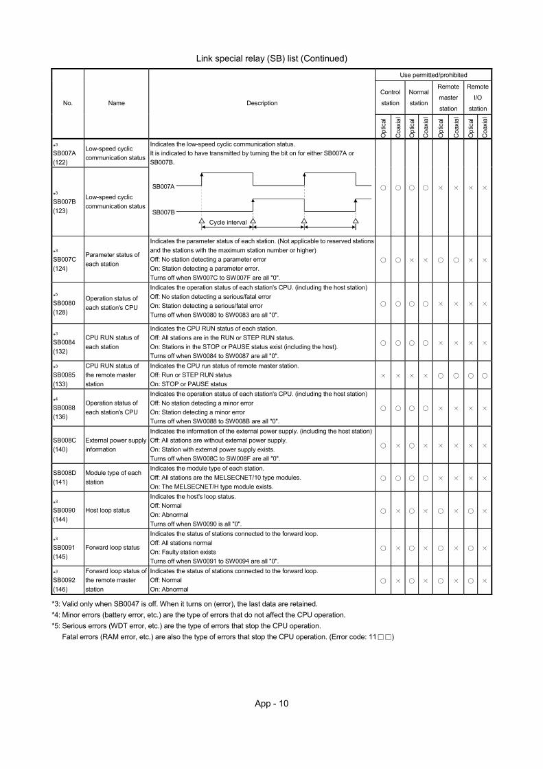
App - 10
Link special relay (SB) list (Continued)
Use permitted/prohibited
Control
station
Normal
station
Remote
master
station
Remote
I/O
station No. Name Description
Opt
ical
Coa
xial
Opt
ical
Coa
xial
Opt
ical
Coa
xial
Opt
ical
Coa
xial
*3 SB007A (122)
Low-speed cyclic communication status
*3 SB007B (123)
Low-speed cyclic communication status
Indicates the low-speed cyclic communication status. It is indicated to have transmitted by turning the bit on for either SB007A or SB007B.
SB007A
SB007BCycle interval
*3 SB007C (124)
Parameter status of each station
Indicates the parameter status of each station. (Not applicable to reserved stations and the stations with the maximum station number or higher) Off: No station detecting a parameter error On: Station detecting a parameter error. Turns off when SW007C to SW007F are all "0".
*5 SB0080 (128)
Operation status of each station's CPU
Indicates the operation status of each station's CPU. (including the host station) Off: No station detecting a serious/fatal error On: Station detecting a serious/fatal error Turns off when SW0080 to SW0083 are all "0".
*3
SB0084 (132)
CPU RUN status of each station
Indicates the CPU RUN status of each station. Off: All stations are in the RUN or STEP RUN status. On: Stations in the STOP or PAUSE status exist (including the host). Turns off when SW0084 to SW0087 are all "0".
*3
SB0085 (133)
CPU RUN status of the remote master station
Indicates the CPU run status of remote master station. Off: Run or STEP RUN status On: STOP or PAUSE status
*4
SB0088 (136)
Operation status of each station's CPU
Indicates the operation status of each station's CPU. (including the host station) Off: No station detecting a minor error On: Station detecting a minor error Turns off when SW0088 to SW008B are all "0".
SB008C (140)
External power supply information
Indicates the information of the external power supply. (including the host station)Off: All stations are without external power supply. On: Station with external power supply exists. Turns off when SW008C to SW008F are all "0".
SB008D (141)
Module type of each station
Indicates the module type of each station. Off: All stations are the MELSECNET/10 type modules. On: The MELSECNET/H type module exists.
*3 SB0090 (144)
Host loop status
Indicates the host's loop status. Off: Normal On: Abnormal Turns off when SW0090 is all "0".
*3 SB0091 (145)
Forward loop status
Indicates the status of stations connected to the forward loop. Off: All stations normal On: Faulty station exists Turns off when SW0091 to SW0094 are all "0".
*3 SB0092 (146)
Forward loop status of the remote master station
Indicates the status of stations connected to the forward loop. Off: Normal On: Abnormal
*3: Valid only when SB0047 is off. When it turns on (error), the last data are retained. *4: Minor errors (battery error, etc.) are the type of errors that do not affect the CPU operation. *5: Serious errors (WDT error, etc.) are the type of errors that stop the CPU operation.
Fatal errors (RAM error, etc.) are also the type of errors that stop the CPU operation. (Error code: 11 )
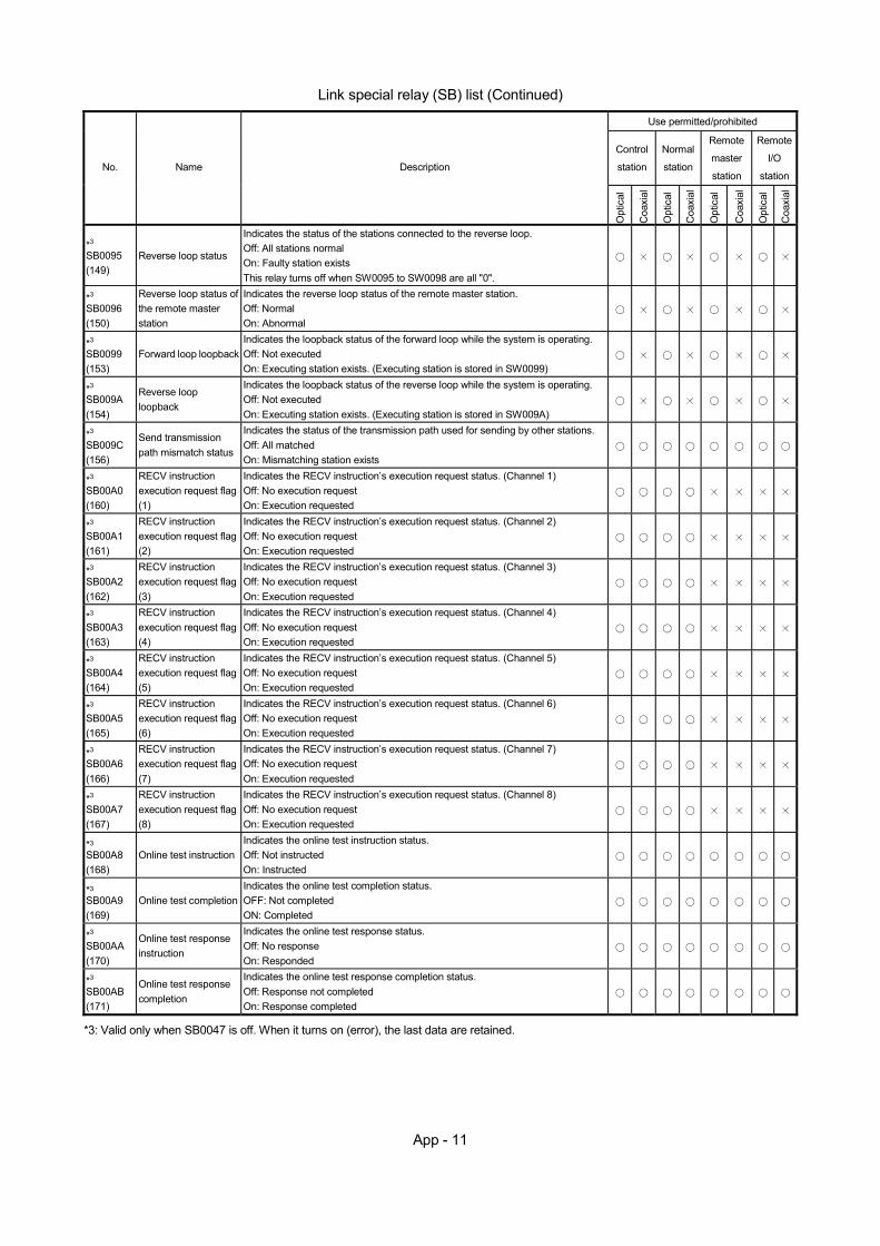
App - 11
Link special relay (SB) list (Continued)
Use permitted/prohibited
Control
station
Normal
station
Remote
master
station
Remote
I/O
station No. Name Description
Opt
ical
Coa
xial
Opt
ical
Coa
xial
Opt
ical
Coa
xial
Opt
ical
Coa
xial
*3 SB0095 (149)
Reverse loop status
Indicates the status of the stations connected to the reverse loop. Off: All stations normal On: Faulty station exists This relay turns off when SW0095 to SW0098 are all "0".
*3 SB0096 (150)
Reverse loop status of the remote master station
Indicates the reverse loop status of the remote master station. Off: Normal On: Abnormal
*3 SB0099 (153)
Forward loop loopback Indicates the loopback status of the forward loop while the system is operating. Off: Not executed On: Executing station exists. (Executing station is stored in SW0099)
*3 SB009A (154)
Reverse loop loopback
Indicates the loopback status of the reverse loop while the system is operating. Off: Not executed On: Executing station exists. (Executing station is stored in SW009A)
*3 SB009C (156)
Send transmission path mismatch status
Indicates the status of the transmission path used for sending by other stations. Off: All matched On: Mismatching station exists
*3 SB00A0 (160)
RECV instruction execution request flag (1)
Indicates the RECV instruction’s execution request status. (Channel 1) Off: No execution request On: Execution requested
*3 SB00A1 (161)
RECV instruction execution request flag (2)
Indicates the RECV instruction’s execution request status. (Channel 2) Off: No execution request On: Execution requested
*3 SB00A2 (162)
RECV instruction execution request flag (3)
Indicates the RECV instruction’s execution request status. (Channel 3) Off: No execution request On: Execution requested
*3 SB00A3 (163)
RECV instruction execution request flag (4)
Indicates the RECV instruction’s execution request status. (Channel 4) Off: No execution request On: Execution requested
*3 SB00A4 (164)
RECV instruction execution request flag (5)
Indicates the RECV instruction’s execution request status. (Channel 5) Off: No execution request On: Execution requested
*3 SB00A5 (165)
RECV instruction execution request flag (6)
Indicates the RECV instruction’s execution request status. (Channel 6) Off: No execution request On: Execution requested
*3 SB00A6 (166)
RECV instruction execution request flag (7)
Indicates the RECV instruction’s execution request status. (Channel 7) Off: No execution request On: Execution requested
*3 SB00A7 (167)
RECV instruction execution request flag (8)
Indicates the RECV instruction’s execution request status. (Channel 8) Off: No execution request On: Execution requested
*3 SB00A8 (168)
Online test instruction Indicates the online test instruction status. Off: Not instructed On: Instructed
*3 SB00A9 (169)
Online test completion Indicates the online test completion status. OFF: Not completed ON: Completed
*3 SB00AA (170)
Online test response instruction
Indicates the online test response status. Off: No response On: Responded
*3 SB00AB (171)
Online test response completion
Indicates the online test response completion status. Off: Response not completed On: Response completed
*3: Valid only when SB0047 is off. When it turns on (error), the last data are retained.
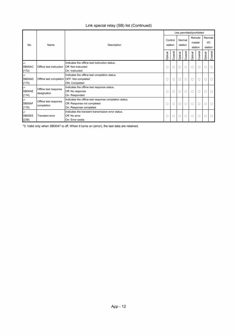
App - 12
Link special relay (SB) list (Continued)
Use permitted/prohibited
Control
station
Normal
station
Remote
master
station
Remote
I/O
station No. Name Description
Opt
ical
Coa
xial
Opt
ical
Coa
xial
Opt
ical
Coa
xial
Opt
ical
Coa
xial
*3 SB00AC (172)
Offline test instruction Indicates the offline test instruction status. Off: Not instructed On: Instructed
*3 SB00AD (173)
Offline test completion Indicates the offline test completion status. OFF: Not completed ON: Completed
*3 SB00AE (174)
Offline test response designation
Indicates the offline test response status. Off: No response On: Responded
*3 SB00AF (175)
Offline test response completion
Indicates the offline test response completion status. Off: Response not completed On: Response completed
*3 SB00EE (238)
Transient error Indicates the transient transmission error status. Off: No error On: Error exists
*3: Valid only when SB0047 is off. When it turns on (error), the last data are retained.
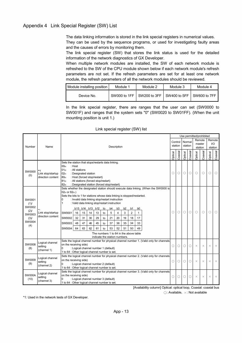
App - 13
Appendix 4 Link Special Register (SW) List
The data linking information is stored in the link special registers in numerical values. They can be used by the sequence programs, or used for investigating faulty areas and the causes of errors by monitoring them. The link special register (SW) that stores the link status is used for the detailed information of the network diagnostics of GX Developer. When multiple network modules are installed, the SW of each network module is refreshed to the SW of the CPU module shown below if each network module's refresh parameters are not set. If the refresh parameters are set for at least one network module, the refresh parameters of all the network modules should be reviewed.
Module installing position Module 1 Module 2 Module 3 Module 4
Device No. SW000 to 1FF SW200 to 3FF SW400 to 5FF SW600 to 7FF
In the link special register, there are ranges that the user can set (SW0000 to SW001F) and ranges that the system sets "0" (SW0020 to SW01FF). (When the unit mounting position is unit 1.)
Link special register (SW) list
Use permitted/prohibited
Control station
Normal station
Remote master station
Remote I/O
station Number Name Description
Opt
ical
Coa
xial
Opt
ical
Coa
xial
Opt
ical
Coa
xial
Opt
ical
Coa
xial
SW0000 (0)
*1 Link stop/startup direction content
Sets the station that stops/restarts data linking. 00H : Host 01H : All stations 02H : Designated station 80H : Host (forced stop/restart) 81H : All stations (forced stop/restart) 82H : Designated station (forced stop/restart)
SW0001 (1)/
SW0002 (2)/
SW0003 (3)/
SW0004 (4)
*1 Link stop/startup direction content
Sets whether the designated station should execute data linking. (When the SW0000 is 02H or 82H.) Sets the bits to 1 for stations whose data linking is stopped/restarted. 0 : Invalid data linking stop/restart instruction 1 : Valid data linking stop/restart instruction
16
32
48
64
15 14 13 5 4 3 2 1
31 30
47 46
63 62
29
45
61
21 20 19 18 17
37 36 35 34 33
53 52 51 50 49
to
to
to
to
b15 b14 b13 b12 b4 b3 b2 b1 b0SW0001
SW0002
SW0003
SW0004
The numbers 1 to 64 in the above table indicate the station numbers.
to
SW0008 (8)
Logical channel setting (channel 1)
Sets the logical channel number for physical channel number 1. (Valid only for channels on the receiving side) 0 : Logical channel number 1 (default) 1 to 64 : Other logical channel number is set.
SW0009 (9)
Logical channel setting (channel 2)
Sets the logical channel number for physical channel number 2. (Valid only for channels on the receiving side) 0 : Logical channel number 2 (default) 1 to 64 : Other logical channel number is set.
SW000A (10)
Logical channel setting (channel 3)
Sets the logical channel number for physical channel number 3. (Valid only for channels on the receiving side) 0 : Logical channel number 3 (default) 1 to 64 : Other logical channel number is set.
[Availability column] Optical: optical loop, Coaxial: coaxial bus : Available, : Not available
*1: Used in the network tests of GX Developer.
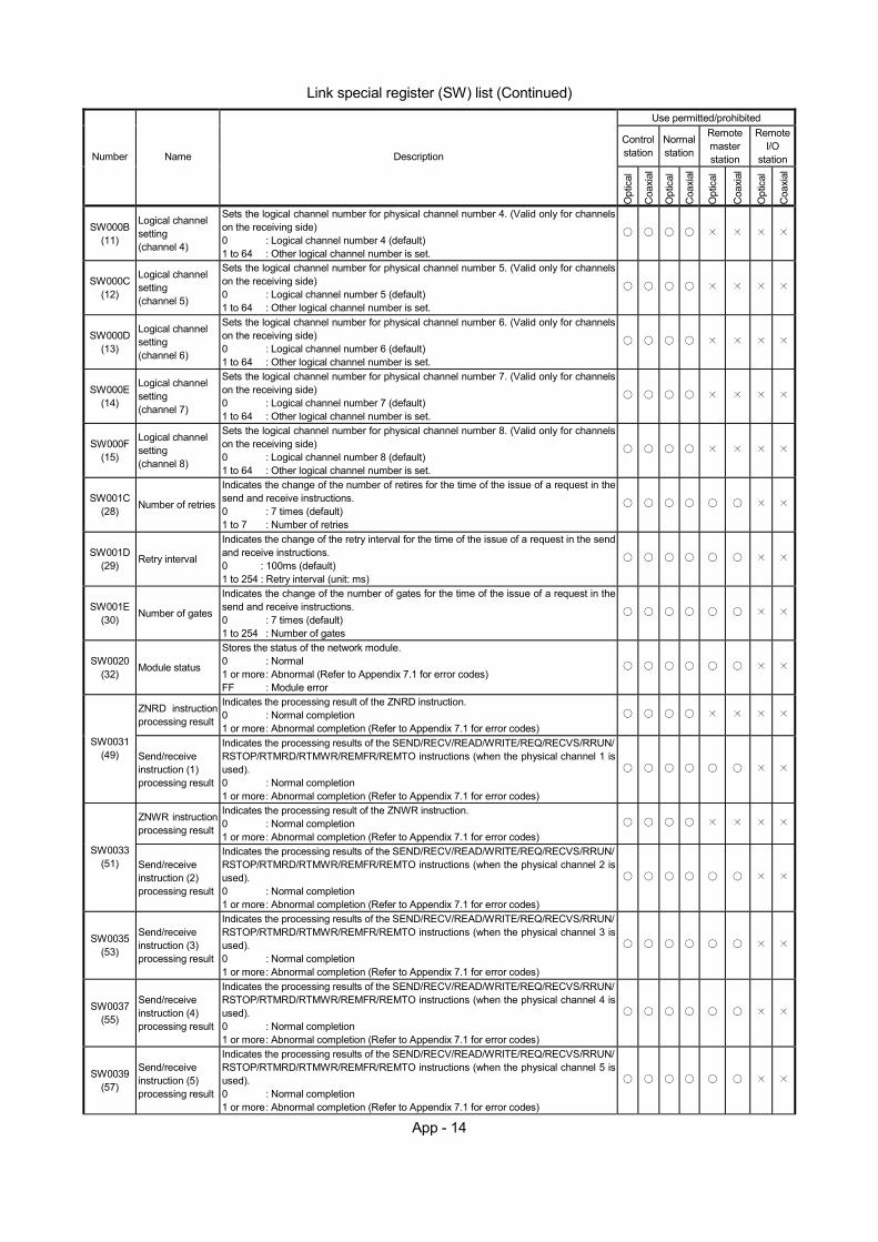
App - 14
Link special register (SW) list (Continued)
Use permitted/prohibited
Control station
Normal station
Remote master station
Remote I/O
station Number Name Description
Opt
ical
Coa
xial
Opt
ical
Coa
xial
Opt
ical
Coa
xial
Opt
ical
Coa
xial
SW000B (11)
Logical channel setting (channel 4)
Sets the logical channel number for physical channel number 4. (Valid only for channels on the receiving side) 0 : Logical channel number 4 (default) 1 to 64 : Other logical channel number is set.
SW000C (12)
Logical channel setting (channel 5)
Sets the logical channel number for physical channel number 5. (Valid only for channels on the receiving side) 0 : Logical channel number 5 (default) 1 to 64 : Other logical channel number is set.
SW000D (13)
Logical channel setting (channel 6)
Sets the logical channel number for physical channel number 6. (Valid only for channels on the receiving side) 0 : Logical channel number 6 (default) 1 to 64 : Other logical channel number is set.
SW000E (14)
Logical channel setting (channel 7)
Sets the logical channel number for physical channel number 7. (Valid only for channels on the receiving side) 0 : Logical channel number 7 (default) 1 to 64 : Other logical channel number is set.
SW000F (15)
Logical channel setting (channel 8)
Sets the logical channel number for physical channel number 8. (Valid only for channels on the receiving side) 0 : Logical channel number 8 (default) 1 to 64 : Other logical channel number is set.
SW001C (28) Number of retries
Indicates the change of the number of retires for the time of the issue of a request in the send and receive instructions. 0 : 7 times (default) 1 to 7 : Number of retries
SW001D (29) Retry interval
Indicates the change of the retry interval for the time of the issue of a request in the send and receive instructions. 0 : 100ms (default) 1 to 254 : Retry interval (unit: ms)
SW001E (30) Number of gates
Indicates the change of the number of gates for the time of the issue of a request in the send and receive instructions. 0 : 7 times (default) 1 to 254 : Number of gates
SW0020 (32) Module status
Stores the status of the network module. 0 : Normal 1 or more : Abnormal (Refer to Appendix 7.1 for error codes) FF : Module error
ZNRD instruction processing result
Indicates the processing result of the ZNRD instruction. 0 : Normal completion 1 or more : Abnormal completion (Refer to Appendix 7.1 for error codes)
SW0031 (49) Send/receive
instruction (1) processing result
Indicates the processing results of the SEND/RECV/READ/WRITE/REQ/RECVS/RRUN/RSTOP/RTMRD/RTMWR/REMFR/REMTO instructions (when the physical channel 1 is used). 0 : Normal completion 1 or more : Abnormal completion (Refer to Appendix 7.1 for error codes)
ZNWR instruction processing result
Indicates the processing result of the ZNWR instruction. 0 : Normal completion 1 or more : Abnormal completion (Refer to Appendix 7.1 for error codes)
SW0033 (51) Send/receive
instruction (2) processing result
Indicates the processing results of the SEND/RECV/READ/WRITE/REQ/RECVS/RRUN/RSTOP/RTMRD/RTMWR/REMFR/REMTO instructions (when the physical channel 2 is used). 0 : Normal completion 1 or more : Abnormal completion (Refer to Appendix 7.1 for error codes)
SW0035 (53)
Send/receive instruction (3) processing result
Indicates the processing results of the SEND/RECV/READ/WRITE/REQ/RECVS/RRUN/RSTOP/RTMRD/RTMWR/REMFR/REMTO instructions (when the physical channel 3 is used). 0 : Normal completion 1 or more : Abnormal completion (Refer to Appendix 7.1 for error codes)
SW0037 (55)
Send/receive instruction (4) processing result
Indicates the processing results of the SEND/RECV/READ/WRITE/REQ/RECVS/RRUN/RSTOP/RTMRD/RTMWR/REMFR/REMTO instructions (when the physical channel 4 is used). 0 : Normal completion 1 or more : Abnormal completion (Refer to Appendix 7.1 for error codes)
SW0039 (57)
Send/receive instruction (5) processing result
Indicates the processing results of the SEND/RECV/READ/WRITE/REQ/RECVS/RRUN/RSTOP/RTMRD/RTMWR/REMFR/REMTO instructions (when the physical channel 5 is used). 0 : Normal completion 1 or more : Abnormal completion (Refer to Appendix 7.1 for error codes)
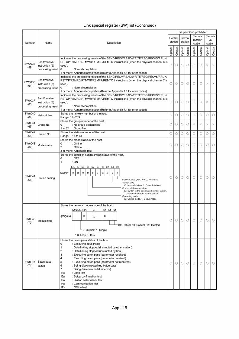
App - 15
Link special register (SW) list (Continued)
Use permitted/prohibited
Control station
Normal station
Remote master station
Remote I/O
station Number Name Description
Opt
ical
Coa
xial
Opt
ical
Coa
xial
Opt
ical
Coa
xial
Opt
ical
Coa
xial
SW003B (59)
Send/receive instruction (6) processing result
Indicates the processing results of the SEND/RECV/READ/WRITE/REQ/RECVS/RRUN/RSTOP/RTMRD/RTMWR/REMFR/REMTO instructions (when the physical channel 6 is used). 0 : Normal completion 1 or more : Abnormal completion (Refer to Appendix 7.1 for error codes)
SW003D (61)
Send/receive instruction (7) processing result
Indicates the processing results of the SEND/RECV/READ/WRITE/REQ/RECVS/RRUN/RSTOP/RTMRD/RTMWR/REMFR/REMTO instructions (when the physical channel 7 is used). 0 : Normal completion 1 or more : Abnormal completion (Refer to Appendix 7.1 for error codes)
SW003F (63)
Send/receive instruction (8) processing result
Indicates the processing results of the SEND/RECV/READ/WRITE/REQ/RECVS/RRUN/RSTOP/RTMRD/RTMWR/REMFR/REMTO instructions (when the physical channel 8 is used). 0 : Normal completion 1 or more : Abnormal completion (Refer to Appendix 7.1 for error codes)
SW0040 (64) Network No. Stores the network number of the host.
Range: 1 to 239
SW0041 (65) Group No.
Stores the group number of the host. 0 : No group designation 1 to 32 : Group No.
SW0042 (66) Station No. Stores the station number of the host.
Range : 1 to 64
SW0043 (67) Mode status
Stores the mode status of the host. 0 : Online 2 : Offline 3 or more : Applicable test
SW0044 (68) Station setting
Stores the condition setting switch status of the host. 0 : OFF 1 : ON
0 to 9 8 7 3 2 1SW0044
b15 to b8 b7 b6 b2 b1 b0
0
b9
Network type (PLC to PLC network)Station type
(0: Normal station, 1: Control station)Control station operation
(0: Switch to the designated control station,1: Keep the current control station)
Operating mode(0: Online mode, 1: Debug mode)
to
to
SW0046 (70) Module type
Stores the network module type of the host.
0 0SW0046
b15b14b13 to b2 b1 b0
to
0: Duplex 1: Single
01: Optical 10: Coaxial 11: Twisted
0: Loop 1: Bus
SW0047 (71)
Baton pass status
Stores the baton pass status of the host. 0 : Executing data linking 1 : Data linking stopped (instructed by other station) 2 : Data linking stopped (instructed by host) 3 : Executing baton pass (parameter received) 4 : Executing baton pass (parameter received) 5 : Executing baton pass (parameter not received) 6 : Being disconnected (no baton pass) 7 : Being disconnected (line error) 11H : Loop test 12H : Setup confirmation test 13H : Station order check test 14H : Communication test 1FH : Offline test
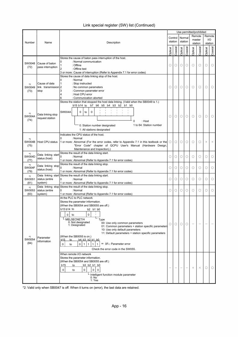
App - 16
Link special register (SW) list (Continued)
Use permitted/prohibited
Control station
Normal station
Remote master station
Remote I/O
station Number Name Description
Opt
ical
Coa
xial
Opt
ical
Coa
xial
Opt
ical
Coa
xial
Opt
ical
Coa
xial
SW0048 (72)
Cause of baton pass interruption
Stores the cause of baton pass interruption of the host. 0 : Normal communication 1 : Offline 2 : Offline test 3 or more : Cause of interruption (Refer to Appendix 7.1 for error codes)
*2 SW0049
(73)
Cause of data link transmission stop
Stores the cause of data linking stop of the host. 0 : Normal 1 : Stop instructed 2 : No common parameters 3 : Common parameter error 4 : Host CPU error 6 : Communication aborted
*2 SW004A
(74)
Data linking stop request station
Stores the station that stopped the host data linking. (Valid when the SB0049 is 1.)
toSW004A
0 : Host1 to 64: Station number
b15 b14 to b2 b1 b0
0: Station number designated1: All stations designated
b7 b6 b5 b4 b3
0 0
*2 SW004B
(75) Host CPU status
Indicates the CPU status of the host. 0 : Normal 1 or more : Abnormal (For the error codes, refer to Appendix 7.1 in this textbook or the
"Error Code" chapter of QCPU User's Manual (Hardware Design, Maintenance and Inspection).)
*2 SW004D
(77)
Data linking start status (host)
Stores the result of the data linking start. 0 : Normal 1 or more : Abnormal (Refer to Appendix 7.1 for error codes)
*2 SW004F
(79)
Data linking stop status (host)
Stores the result of the data linking stop. 0 : Normal 1 or more : Abnormal (Refer to Appendix 7.1 for error codes)
*2 SW0051
(81)
Data linking start status (entire system)
Stores the result of the data linking start. 0 : Normal 1 or more : Abnormal (Refer to Appendix 7.1 for error codes)
*2 SW0053
(83)
Data linking stop status (entire system)
Stores the result of the data linking stop. 0 : Normal 1 or more : Abnormal (Refer to Appendix 7.1 for error codes)
At the PLC to PLC network Stores the parameter information. (When the SB0054 and SB0055 are off.)
0 0
b15 b14 to b2 b1 b0
to
MELSECNET/H0: Not designated1: Designated
Type00: Use only common parameters01: Common parameters + station specific parameters10: Use only default parameters11: Default parameters + station specific parameters
(When the SB0055 is on.)
0b15 b2 b1 b0
tob3b410 1 1 1 0FH: Parameter error
Check the error code in the SW055.
to
*2 SW0054
(84)
Parameter information
When remote I/O network Stores the parameter information. (When the SB0054 and SB0055 are off.)
0
b15 b2 b1 b0
to
b3
0 0 0
to
Intelligent function module parameter0: No1: Yes
*2: Valid only when SB0047 is off. When it turns on (error), the last data are retained.
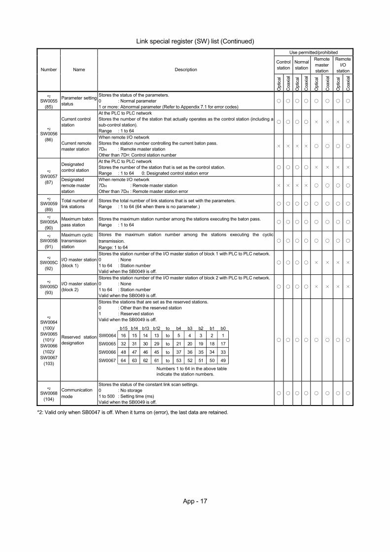
App - 17
Link special register (SW) list (Continued)
Use permitted/prohibited
Control station
Normal station
Remote master station
Remote I/O
station Number Name Description
Opt
ical
Coa
xial
Opt
ical
Coa
xial
Opt
ical
Coa
xial
Opt
ical
Coa
xial
*2 SW0055
(85)
Parameter setting status
Stores the status of the parameters. 0 : Normal parameter 1 or more : Abnormal parameter (Refer to Appendix 7.1 for error codes)
Current control station
At the PLC to PLC network Stores the number of the station that actually operates as the control station (including a sub-control station). Range : 1 to 64
*2 SW0056
(86) Current remote master station
When remote I/O network Stores the station number controlling the current baton pass. 7DH : Remote master station Other than 7DH: Control station number
Designated control station
At the PLC to PLC network Stores the number of the station that is set as the control station. Range : 1 to 64 0: Designated control station error
*2
SW0057 (87) Designated
remote master station
When remote I/O network 7DH : Remote master station Other than 7DH : Remote master station error
*2 SW0059
(89)
Total number of link stations
Stores the total number of link stations that is set with the parameters. Range : 1 to 64 (64 when there is no parameter.)
*2 SW005A
(90)
Maximum baton pass station
Stores the maximum station number among the stations executing the baton pass. Range : 1 to 64
*2 SW005B
(91)
Maximum cyclic transmission station
Stores the maximum station number among the stations executing the cyclic transmission. Range: 1 to 64
*2 SW005C
(92)
I/O master station (block 1)
Stores the station number of the I/O master station of block 1 with PLC to PLC network. 0 : None 1 to 64 : Station number Valid when the SB0049 is off.
*2 SW005D
(93)
I/O master station (block 2)
Stores the station number of the I/O master station of block 2 with PLC to PLC network. 0 : None 1 to 64 : Station number Valid when the SB0049 is off.
*2 SW0064
(100)/ SW0065
(101)/ SW0066
(102)/ SW0067
(103)
Reserved station designation
Stores the stations that are set as the reserved stations. 0 : Other than the reserved station 1 : Reserved station Valid when the SB0049 is off.
16
32
48
64
15 14 13 5 4 3 2 1
31 30
47 46
63 62
29
45
61
21 20 19 18 17
37 36 35 34 33
53 52 51 50 49
to
to
to
to
b15 b14 b13 b12 b4 b3 b2 b1 b0SW0064
SW0065
SW0066
SW0067
Numbers 1 to 64 in the above table indicate the station numbers.
to
*2 SW0068
(104)
Communication mode
Stores the status of the constant link scan settings. 0 : No storage 1 to 500 : Setting time (ms) Valid when the SB0049 is off.
*2: Valid only when SB0047 is off. When it turns on (error), the last data are retained.
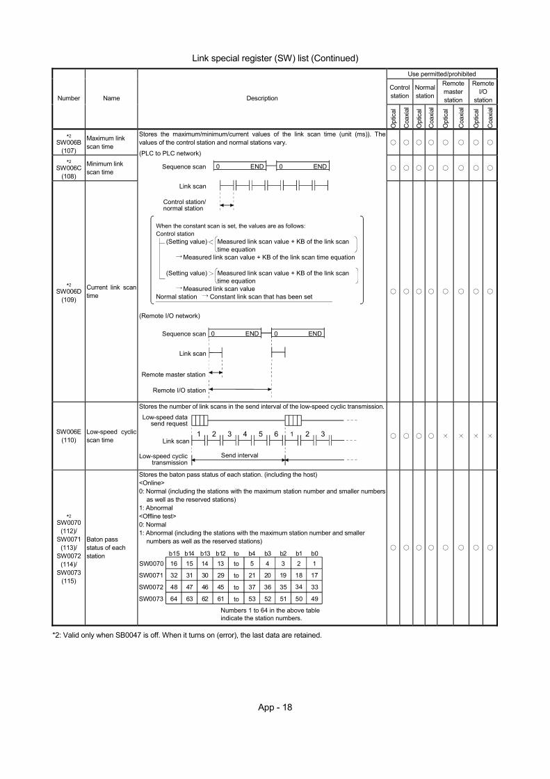
App - 18
Link special register (SW) list (Continued)
Use permitted/prohibited
Control station
Normal station
Remote master station
Remote I/O
station Number Name Description
Opt
ical
Coa
xial
Opt
ical
Coa
xial
Opt
ical
Coa
xial
Opt
ical
Coa
xial
*2 SW006B
(107)
Maximum link scan time
*2 SW006C
(108)
Minimum link scan time
*2 SW006D
(109)
Current link scan time
Stores the maximum/minimum/current values of the link scan time (unit (ms)). The values of the control station and normal stations vary.
Sequence scan
Link scan
Control station/normal station
0 END 0 END
When the constant scan is set, the values are as follows:Control station
(Setting value) Measured link scan value + KB of the link scan time equation
Measured link scan value + KB of the link scan time equation
(Setting value) Measured link scan value + KB of the link scan time equation
Measured link scan valueNormal station Constant link scan that has been set
(PLC to PLC network)
Sequence scan
Link scan
Remote I/O station
0 END 0 END
(Remote I/O network)
Remote master station
SW006E (110)
Low-speed cyclic scan time
Stores the number of link scans in the send interval of the low-speed cyclic transmission. Low-speed data
send request
Link scan
Low-speed cyclictransmission
1 2 3 4 5 6 1 2 3
Send interval
*2 SW0070
(112)/ SW0071
(113)/ SW0072
(114)/ SW0073
(115)
Baton pass status of each station
Stores the baton pass status of each station. (including the host) <Online> 0: Normal (including the stations with the maximum station number and smaller numbers
as well as the reserved stations) 1: Abnormal <Offline test> 0: Normal 1: Abnormal (including the stations with the maximum station number and smaller
numbers as well as the reserved stations)
16
32
48
64
15 14 13 5 4 3 2 1
31 30
47 46
63 62
29
45
61
21 20 19 18 17
37 36 35 34 33
53 52 51 50 49
to
to
to
to
b15 b14 b13 b12 b4 b3 b2 b1 b0SW0070
SW0071
SW0072
SW0073
Numbers 1 to 64 in the above table indicate the station numbers.
to
*2: Valid only when SB0047 is off. When it turns on (error), the last data are retained.
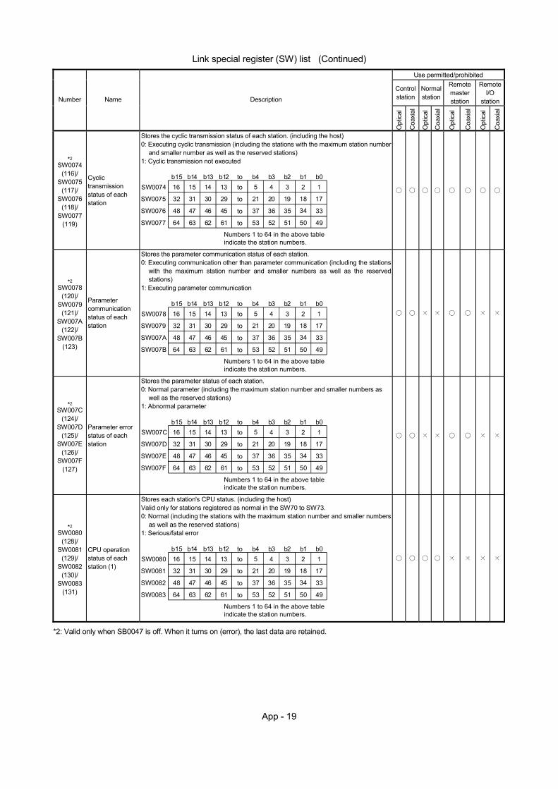
App - 19
Link special register (SW) list (Continued)
Use permitted/prohibited
Control station
Normal station
Remote master station
Remote I/O
station Number Name Description
Opt
ical
Coa
xial
Opt
ical
Coa
xial
Opt
ical
Coa
xial
Opt
ical
Coa
xial
*2 SW0074
(116)/ SW0075
(117)/ SW0076
(118)/ SW0077
(119)
Cyclic transmission status of each station
Stores the cyclic transmission status of each station. (including the host) 0: Executing cyclic transmission (including the stations with the maximum station number
and smaller number as well as the reserved stations) 1: Cyclic transmission not executed
16
32
48
64
15 14 13 5 4 3 2 1
31 30
47 46
63 62
29
45
61
21 20 19 18 17
37 36 35 34 33
53 52 51 50 49
to
to
to
to
b15 b14 b13 b12 b4 b3 b2 b1 b0SW0074
SW0075
SW0076
SW0077
Numbers 1 to 64 in the above table indicate the station numbers.
to
*2 SW0078
(120)/ SW0079
(121)/ SW007A
(122)/ SW007B
(123)
Parameter communication status of each station
Stores the parameter communication status of each station. 0: Executing communication other than parameter communication (including the stations
with the maximum station number and smaller numbers as well as the reserved stations)
1: Executing parameter communication
16
32
48
64
15 14 13 5 4 3 2 1
31 30
47 46
63 62
29
45
61
21 20 19 18 17
37 36 35 34 33
53 52 51 50 49
to
to
to
to
b15 b14 b13 b12 b4 b3 b2 b1 b0SW0078
SW0079
SW007A
SW007B
Numbers 1 to 64 in the above table indicate the station numbers.
to
*2 SW007C
(124)/ SW007D
(125)/ SW007E
(126)/ SW007F
(127)
Parameter error status of each station
Stores the parameter status of each station. 0: Normal parameter (including the maximum station number and smaller numbers as
well as the reserved stations) 1: Abnormal parameter
16
32
48
64
15 14 13 5 4 3 2 1
31 30
47 46
63 62
29
45
61
21 20 19 18 17
37 36 35 34 33
53 52 51 50 49
to
to
to
to
b15 b14 b13 b12 b4 b3 b2 b1 b0SW007C
SW007D
SW007E
SW007F
Numbers 1 to 64 in the above table indicate the station numbers.
to
*2 SW0080
(128)/ SW0081
(129)/ SW0082
(130)/ SW0083
(131)
CPU operation status of each station (1)
Stores each station's CPU status. (including the host) Valid only for stations registered as normal in the SW70 to SW73. 0: Normal (including the stations with the maximum station number and smaller numbers
as well as the reserved stations) 1: Serious/fatal error
16
32
48
64
15 14 13 5 4 3 2 1
31 30
47 46
63 62
29
45
61
21 20 19 18 17
37 36 35 34 33
53 52 51 50 49
to
to
to
to
b15 b14 b13 b12 b4 b3 b2 b1 b0SW0080
SW0081
SW0082
SW0083
Numbers 1 to 64 in the above table indicate the station numbers.
to
*2: Valid only when SB0047 is off. When it turns on (error), the last data are retained.

App - 20
Link special register (SW) list (Continued)
Use permitted/prohibited
Control station
Normal station
Remote master station
Remote I/O
station Number Name Description
Opt
ical
Coa
xial
Opt
ical
Coa
xial
Opt
ical
Coa
xial
Opt
ical
Coa
xial
*2 SW0084
(132)/ SW0085
(133)/ SW0086
(134)/ SW0087
(135)
CPU RUN status of each station
Stores the CPU RUN status of each station. (including the host) Valid only for stations registered as normal in the SW70 to SW73. 0: RUN or STEP RUN (including the stations with the maximum station number and
smaller numbers as well as the reserved stations) 1: STOP,PAUSE,ERROR
16
32
48
64
15 14 13 5 4 3 2 1
31 30
47 46
63 62
29
45
61
21 20 19 18 17
37 36 35 34 33
53 52 51 50 49
to
to
to
to
b15 b14 b13 b12 b4 b3 b2 b1 b0SW0084
SW0085
SW0086
SW0087
Numbers 1 to 64 in the above table indicate the station numbers.
to
*2 SW0088
(136)/ SW0089
(137)/ SW008A
(138)/ SW008B
(139)
CPU operation status of each station (2)
Stores each station's CPU status. (including the host) Valid only for stations registered as normal in the SW70 to SW73. 0: Normal (including the stations with the maximum station number and smaller numbers
as well as the reserved stations) 1: Minor error
16
32
48
64
15 14 13 5 4 3 2 1
31 30
47 46
63 62
29
45
61
21 20 19 18 17
37 36 35 34 33
53 52 51 50 49
to
to
to
to
b15 b14 b13 b12 b4 b3 b2 b1 b0SW0088
SW0089
SW008A
SW008B
Numbers 1 to 64 in the above table indicate the station numbers.
to
*2 SW0090
(144)
Loopback information
Stores the loop status of the host. 0: Loop normal 1: Forward loop error 2: Reverse loop error 3: Loopback 4: Data linking disabled
*2 SW0091
(145)/ SW0092
(146)/ SW0093
(147)/ SW0094
(148)
Forward loop status of each station
Stores the forward loop status of each station. (including the host) 0: Normal (including the station with the maximum station number and smaller numbers
as well as the reserved stations) 1: Abnormal
The disconnected station remains in the status when it was disconnected.
16
32
48
64
15 14 13 5 4 3 2 1
31 30
47 46
63 62
29
45
61
21 20 19 18 17
37 36 35 34 33
53 52 51 50 49
to
to
to
to
b15 b14 b13 b12 b4 b3 b2 b1 b0SW0091
SW0092
SW0093
SW0094
Numbers 1 to 64 in the above table indicate the station numbers.
to
*2 SW0095
(149)/ SW0096
(150)/ SW0097
(151)/ SW0098
(152)
Reverse loop status of each station
Stores the reverse loop status of each station. (including the host) 0: Normal (including the stations with the maximum station number and smaller numbers
as well as the reserved stations) 1: Abnormal
The disconnected station remains in the status when it was disconnected.
16
32
48
64
15 14 13 5 4 3 2 1
31 30
47 46
63 62
29
45
61
21 20 19 18 17
37 36 35 34 33
53 52 51 50 49
to
to
to
to
b15 b14 b13 b12 b4 b3 b2 b1 b0SW0095
SW0096
SW0097
SW0098
Numbers 1 to 64 in the above table indicate the station numbers.
to
*2: Valid only when SB0047 is off. When it turns on (error), the last data are retained.
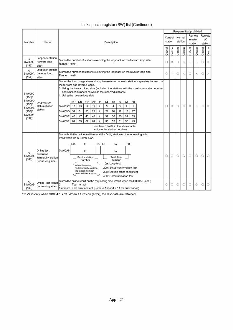
App - 21
Link special register (SW) list (Continued)
Use permitted/prohibited
Control station
Normal station
Remote master station
Remote I/O
stationNumber Name Description
Opt
ical
Coa
xial
Opt
ical
Coa
xial
Opt
ical
Coa
xial
Opt
ical
Coa
xial
*2 SW0099
(153)
Loopback station (forward loop side)
Stores the number of stations executing the loopback on the forward loop side. Range: 1 to 64
*2 SW009A
(154)
Loopback station (reverse loop side)
Stores the number of stations executing the loopback on the reverse loop side. Range: 1 to 64
SW009C (156)/
SW009D (157)/
SW009E (158)/
SW009F (159)
Loop usage status of each station
Stores the loop usage status during transmission at each station, separately for each of the forward and reverse loops. 0: Using the forward loop side (including the stations with the maximum station number
and smaller numbers as well as the reserved stations) 1: Using the reverse loop side
16
32
48
64
15 14 13 5 4 3 2 1
31 30
47 46
63 62
29
45
61
21 20 19 18 17
37 36 35 34 33
53 52 51 50 49
to
to
to
to
b15 b14 b13 b12 b4 b3 b2 b1 b0SW009C
SW009D
SW009E
SW009F
Numbers 1 to 64 in the above table indicate the station numbers.
to
*2 SW00A8
(168)
Online test execution item/faulty station (requesting side)
Stores both the online test item and the faulty station on the requesting side. Valid when the SB00A9 is on.
SW00A8
b15 b0
to
to b8 b7
to
to
Faulty stationnumber
Test itemnumber
10H: Loop test20H: Setup confirmation test30H: Station order check test40H: Communication test
When there are multiple faulty stations, the station number detected first is stored.
*2 SW00A9
(169)
Online test result (requesting side)
Stores the online result on the requesting side. (Valid when the SB00A9 is on.) 0 : Test normal 1 or more : Test error content (Refer to Appendix 7.1 for error codes)
*2: Valid only when SB0047 is off. When it turns on (error), the last data are retained.
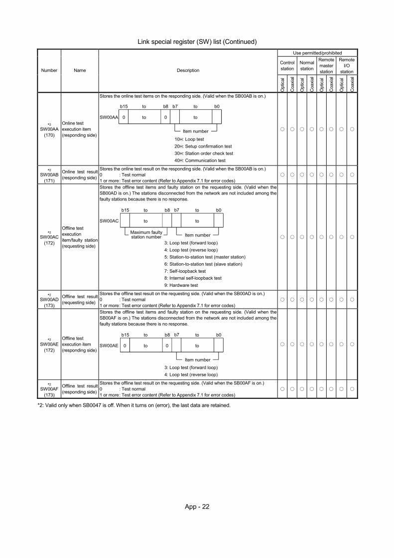
App - 22
Link special register (SW) list (Continued)
Use permitted/prohibited
Control station
Normal station
Remote master station
Remote I/O
station Number Name Description
Opt
ical
Coa
xial
Opt
ical
Coa
xial
Opt
ical
Coa
xial
Opt
ical
Coa
xial
*2 SW00AA
(170)
Online test execution item (responding side)
Stores the online test items on the responding side. (Valid when the SB00AB is on.)
SW00AA
b15 b0
to
to b8 b7
to
to
Item number
10H: Loop test20H: Setup confirmation test30H: Station order check test40H: Communication test
0 0
*2 SW00AB
(171)
Online test result (responding side)
Stores the online test result on the responding side. (Valid when the SB00AB is on.) 0 : Test normal 1 or more : Test error content (Refer to Appendix 7.1 for error codes)
*2 SW00AC
(172)
Offline test execution item/faulty station (requesting side)
Stores the offline test items and faulty station on the requesting side. (Valid when the SB00AD is on.) The stations disconnected from the network are not included among the faulty stations because there is no response.
SW00AC
b15 b0
to
to b8 b7
to
to
Maximum faultystation number Item number
3: Loop test (forward loop)4: Loop test (reverse loop)5: Station-to-station test (master station)6: Station-to-station test (slave station)7: Self-loopback test8: Internal self-loopback test9: Hardware test
*2 SW00AD
(173)
Offline test result (requesting side)
Stores the offline test result on the requesting side. (Valid when the SB00AD is on.) 0 : Test normal 1 or more : Test error content (Refer to Appendix 7.1 for error codes)
*2 SW00AE
(172)
Offline test execution item (responding side)
Stores the offline test items and faulty station on the requesting side. (Valid when the SB00AF is on.) The stations disconnected from the network are not included among the faulty stations because there is no response.
SW00AE
b15 b0
to
to b8 b7
to
to
Item number
3: Loop test (forward loop)4: Loop test (reverse loop)
0 0
*2 SW00AF
(173)
Offline test result (responding side)
Stores the offline test result on the requesting side. (Valid when the SB00AF is on.) 0 : Test normal 1 or more : Test error content (Refer to Appendix 7.1 for error codes)
*2: Valid only when SB0047 is off. When it turns on (error), the last data are retained.
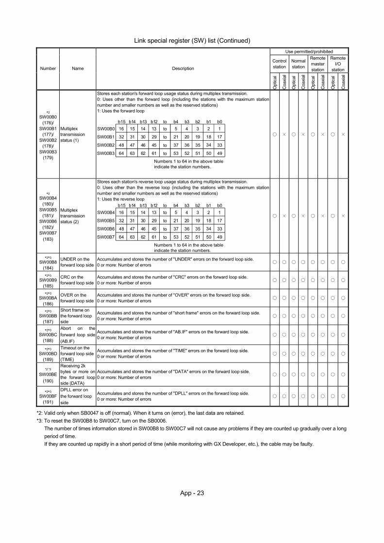
App - 23
Link special register (SW) list (Continued)
Use permitted/prohibited
Control station
Normal station
Remote master station
Remote I/O
station Number Name Description
Opt
ical
Coa
xial
Opt
ical
Coa
xial
Opt
ical
Coa
xial
Opt
ical
Coa
xial
*2 SW00B0
(176)/ SW00B1
(177)/ SW00B2
(178)/ SW00B3
(179)
Multiplex transmission status (1)
Stores each station's forward loop usage status during multiplex transmission. 0: Uses other than the forward loop (including the stations with the maximum station number and smaller numbers as well as the reserved stations) 1: Uses the forward loop
16
32
48
64
15 14 13 5 4 3 2 1
31 30
47 46
63 62
29
45
61
21 20 19 18 17
37 36 35 34 33
53 52 51 50 49
to
to
to
to
b15 b14 b13 b12 b4 b3 b2 b1 b0SW00B0
SW00B1
SW00B2
SW00B3
Numbers 1 to 64 in the above table indicate the station numbers.
to
*2 SW00B4
(180)/ SW00B5
(181)/ SW00B6
(182)/ SW00B7
(183)
Multiplex transmission status (2)
Stores each station's reverse loop usage status during multiplex transmission. 0: Uses other than the reverse loop (including the stations with the maximum station number and smaller numbers as well as the reserved stations) 1: Uses the reverse loop
16
32
48
64
15 14 13 5 4 3 2 1
31 30
47 46
63 62
29
45
61
21 20 19 18 17
37 36 35 34 33
53 52 51 50 49
to
to
to
to
b15 b14 b13 b12 b4 b3 b2 b1 b0SW00B4
SW00B5
SW00B6
SW00B7
Numbers 1 to 64 in the above table indicate the station numbers.
to
*2*3 SW00B8
(184)
UNDER on the forward loop side
Accumulates and stores the number of "UNDER" errors on the forward loop side. 0 or more: Number of errors
*2*3 SW00B9
(185)
CRC on the forward loop side
Accumulates and stores the number of "CRC" errors on the forward loop side. 0 or more: Number of errors
*2*3 SW00BA
(186)
OVER on the forward loop side
Accumulates and stores the number of "OVER" errors on the forward loop side. 0 or more: Number of errors
*2*3 SW00BB
(187)
Short frame on the forward loop side
Accumulates and stores the number of "short frame" errors on the forward loop side. 0 or more: Number of errors
*2*3 SW00BC
(188)
Abort on the forward loop side (AB.IF)
Accumulates and stores the number of "AB.IF" errors on the forward loop side. 0 or more: Number of errors
*2*3 SW00BD
(189)
Timeout on the forward loop side (TIME)
Accumulates and stores the number of "TIME" errors on the forward loop side. 0 or more: Number of errors
*2 *3 SW00BE
(190)
Receiving 2k bytes or more on the forward loop side (DATA)
Accumulates and stores the number of "DATA" errors on the forward loop side. 0 or more: Number of errors
*2*3 SW00BF
(191)
DPLL error on the forward loop side
Accumulates and stores the number of "DPLL" errors on the forward loop side. 0 or more: Number of errors
*2: Valid only when SB0047 is off (normal). When it turns on (error), the last data are retained. *3: To reset the SW00B8 to SW00C7, turn on the SB0006.
The number of times information stored in SW00B8 to SW00C7 will not cause any problems if they are counted up gradually over a long period of time. If they are counted up rapidly in a short period of time (while monitoring with GX Developer, etc.), the cable may be faulty.
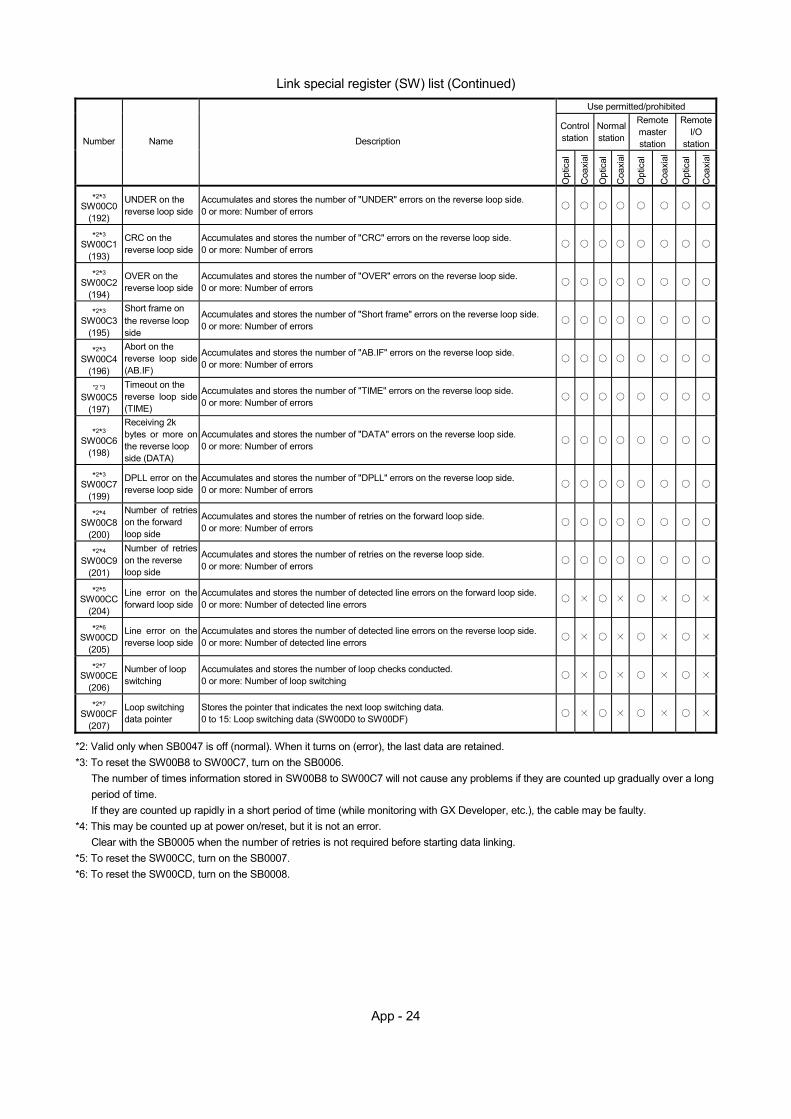
App - 24
Link special register (SW) list (Continued)
Use permitted/prohibited
Control station
Normal station
Remote master station
Remote I/O
station Number Name Description
Opt
ical
Coa
xial
Opt
ical
Coa
xial
Opt
ical
Coa
xial
Opt
ical
Coa
xial
*2*3 SW00C0
(192)
UNDER on the reverse loop side
Accumulates and stores the number of "UNDER" errors on the reverse loop side. 0 or more: Number of errors
*2*3 SW00C1
(193)
CRC on the reverse loop side
Accumulates and stores the number of "CRC" errors on the reverse loop side. 0 or more: Number of errors
*2*3 SW00C2
(194)
OVER on the reverse loop side
Accumulates and stores the number of "OVER" errors on the reverse loop side. 0 or more: Number of errors
*2*3 SW00C3
(195)
Short frame on the reverse loop side
Accumulates and stores the number of "Short frame" errors on the reverse loop side. 0 or more: Number of errors
*2*3 SW00C4
(196)
Abort on the reverse loop side (AB.IF)
Accumulates and stores the number of "AB.IF" errors on the reverse loop side. 0 or more: Number of errors
*2 *3 SW00C5
(197)
Timeout on the reverse loop side (TIME)
Accumulates and stores the number of "TIME" errors on the reverse loop side. 0 or more: Number of errors
*2*3 SW00C6
(198)
Receiving 2k bytes or more on the reverse loop side (DATA)
Accumulates and stores the number of "DATA" errors on the reverse loop side. 0 or more: Number of errors
*2*3 SW00C7
(199)
DPLL error on the reverse loop side
Accumulates and stores the number of "DPLL" errors on the reverse loop side. 0 or more: Number of errors
*2*4 SW00C8
(200)
Number of retries on the forward loop side
Accumulates and stores the number of retries on the forward loop side. 0 or more: Number of errors
*2*4 SW00C9
(201)
Number of retries on the reverse loop side
Accumulates and stores the number of retries on the reverse loop side. 0 or more: Number of errors
*2*5 SW00CC
(204)
Line error on the forward loop side
Accumulates and stores the number of detected line errors on the forward loop side. 0 or more: Number of detected line errors
*2*6 SW00CD
(205)
Line error on the reverse loop side
Accumulates and stores the number of detected line errors on the reverse loop side. 0 or more: Number of detected line errors
*2*7 SW00CE
(206)
Number of loop switching
Accumulates and stores the number of loop checks conducted. 0 or more: Number of loop switching
*2*7 SW00CF
(207)
Loop switching data pointer
Stores the pointer that indicates the next loop switching data. 0 to 15: Loop switching data (SW00D0 to SW00DF)
*2: Valid only when SB0047 is off (normal). When it turns on (error), the last data are retained. *3: To reset the SW00B8 to SW00C7, turn on the SB0006.
The number of times information stored in SW00B8 to SW00C7 will not cause any problems if they are counted up gradually over a long period of time. If they are counted up rapidly in a short period of time (while monitoring with GX Developer, etc.), the cable may be faulty.
*4: This may be counted up at power on/reset, but it is not an error. Clear with the SB0005 when the number of retries is not required before starting data linking.
*5: To reset the SW00CC, turn on the SB0007. *6: To reset the SW00CD, turn on the SB0008.
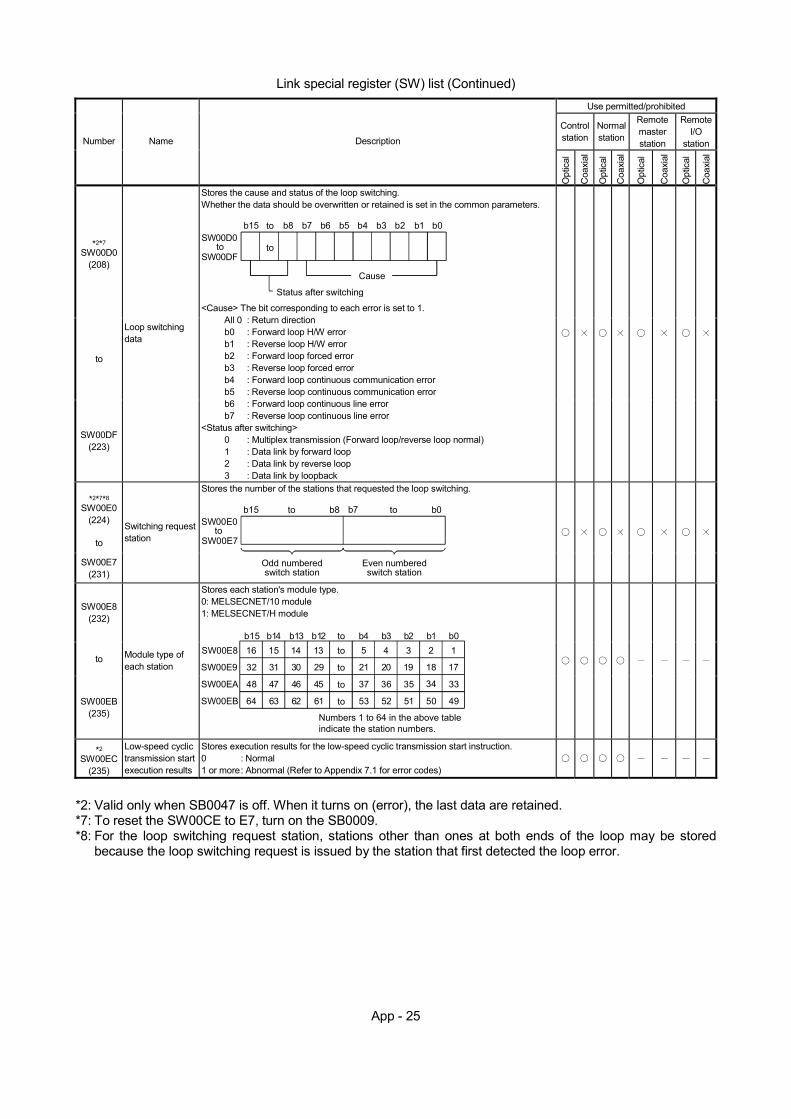
App - 25
Link special register (SW) list (Continued)
Use permitted/prohibited
Control station
Normal station
Remote master station
Remote I/O
station Number Name Description
Opt
ical
Coa
xial
Opt
ical
Coa
xial
Opt
ical
Coa
xial
Opt
ical
Coa
xial
*2*7 SW00D0
(208)
to
SW00DF (223)
Loop switching data
Stores the cause and status of the loop switching. Whether the data should be overwritten or retained is set in the common parameters.
toto
Cause
b15 to b8 b7 b6 b5 b4 b3 b2 b1 b0
Status after switching
SW00D0
SW00DF
<Cause> The bit corresponding to each error is set to 1. All 0 : Return direction b0 : Forward loop H/W error b1 : Reverse loop H/W error b2 : Forward loop forced error b3 : Reverse loop forced error b4 : Forward loop continuous communication error b5 : Reverse loop continuous communication error b6 : Forward loop continuous line error b7 : Reverse loop continuous line error <Status after switching> 0 : Multiplex transmission (Forward loop/reverse loop normal) 1 : Data link by forward loop 2 : Data link by reverse loop 3 : Data link by loopback
*2*7*8 SW00E0
(224)
to
SW00E7 (231)
Switching request station
Stores the number of the stations that requested the loop switching.
b15 b0to
to
b8 b7 to
Odd numberedswitch station
Even numberedswitch station
SW00E0
SW00E7
SW00E8 (232)
to
SW00EB (235)
Module type of each station
Stores each station's module type. 0: MELSECNET/10 module 1: MELSECNET/H module
16
32
48
64
15 14 13 5 4 3 2 1
31 30
47 46
63 62
29
45
61
21 20 19 18 17
37 36 35 34 33
53 52 51 50 49
to
to
to
to
b15 b14 b13 b12 b4 b3 b2 b1 b0SW00E8
SW00E9
SW00EA
SW00EB
Numbers 1 to 64 in the above table indicate the station numbers.
to
*2
SW00EC (235)
Low-speed cyclic transmission start execution results
Stores execution results for the low-speed cyclic transmission start instruction. 0 : Normal 1 or more : Abnormal (Refer to Appendix 7.1 for error codes)
*2: Valid only when SB0047 is off. When it turns on (error), the last data are retained. *7: To reset the SW00CE to E7, turn on the SB0009. *8: For the loop switching request station, stations other than ones at both ends of the loop may be stored
because the loop switching request is issued by the station that first detected the loop error.
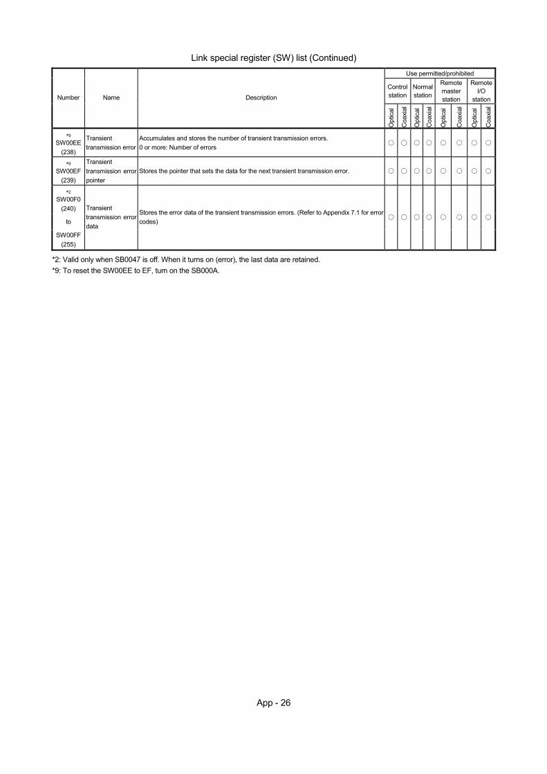
App - 26
Link special register (SW) list (Continued)
Use permitted/prohibited
Control station
Normal station
Remote master station
Remote I/O
station Number Name Description
Opt
ical
Coa
xial
Opt
ical
Coa
xial
Opt
ical
Coa
xial
Opt
ical
Coa
xial
*9 SW00EE
(238)
Transient transmission error
Accumulates and stores the number of transient transmission errors. 0 or more: Number of errors
*9 SW00EF
(239)
Transient transmission error pointer
Stores the pointer that sets the data for the next transient transmission error.
*2 SW00F0
(240)
to
SW00FF (255)
Transient transmission error data
Stores the error data of the transient transmission errors. (Refer to Appendix 7.1 for error codes)
*2: Valid only when SB0047 is off. When it turns on (error), the last data are retained. *9: To reset the SW00EE to EF, turn on the SB000A.
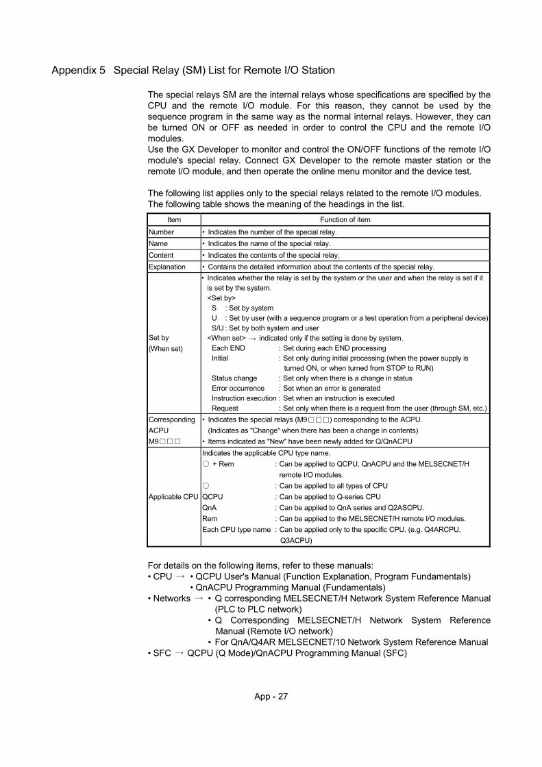
App - 27
Appendix 5 Special Relay (SM) List for Remote I/O Station
The special relays SM are the internal relays whose specifications are specified by the CPU and the remote I/O module. For this reason, they cannot be used by the sequence program in the same way as the normal internal relays. However, they can be turned ON or OFF as needed in order to control the CPU and the remote I/O modules. Use the GX Developer to monitor and control the ON/OFF functions of the remote I/O module's special relay. Connect GX Developer to the remote master station or the remote I/O module, and then operate the online menu monitor and the device test.
The following list applies only to the special relays related to the remote I/O modules. The following table shows the meaning of the headings in the list.
Item Function of item
Number • Indicates the number of the special relay. Name • Indicates the name of the special relay. Content • Indicates the contents of the special relay. Explanation • Contains the detailed information about the contents of the special relay.
Set by (When set)
• Indicates whether the relay is set by the system or the user and when the relay is set if it is set by the system. <Set by>
S : Set by system U : Set by user (with a sequence program or a test operation from a peripheral device)S/U : Set by both system and user
<When set> indicated only if the setting is done by system. Each END : Set during each END processing Initial : Set only during initial processing (when the power supply is
turned ON, or when turned from STOP to RUN) Status change : Set only when there is a change in status Error occurrence : Set when an error is generated Instruction execution : Set when an instruction is executed Request : Set only when there is a request from the user (through SM, etc.)
Corresponding ACPU M9
• Indicates the special relays (M9 ) corresponding to the ACPU. (Indicates as "Change" when there has been a change in contents)
• Items indicated as "New" have been newly added for Q/QnACPU
Applicable CPU
Indicates the applicable CPU type name. + Rem : Can be applied to QCPU, QnACPU and the MELSECNET/H
remote I/O modules. : Can be applied to all types of CPU
QCPU : Can be applied to Q-series CPU QnA : Can be applied to QnA series and Q2ASCPU. Rem : Can be applied to the MELSECNET/H remote I/O modules. Each CPU type name : Can be applied only to the specific CPU. (e.g. Q4ARCPU,
Q3ACPU)
For details on the following items, refer to these manuals: • CPU • QCPU User's Manual (Function Explanation, Program Fundamentals)
• QnACPU Programming Manual (Fundamentals) • Networks • Q corresponding MELSECNET/H Network System Reference Manual
(PLC to PLC network) • Q Corresponding MELSECNET/H Network System Reference
Manual (Remote I/O network) • For QnA/Q4AR MELSECNET/10 Network System Reference Manual
• SFC QCPU (Q Mode)/QnACPU Programming Manual (SFC)
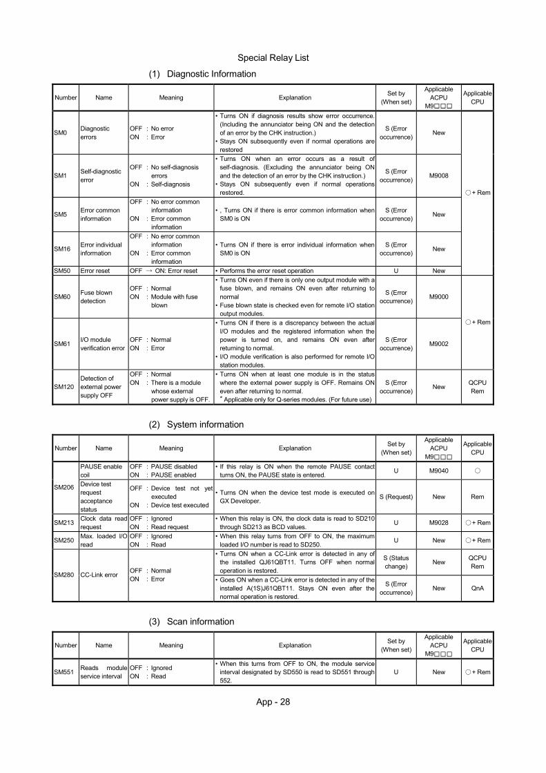
App - 28
Special Relay List
(1) Diagnostic Information Number Name Meaning Explanation Set by
(When set)
Applicable ACPU
M9
Applicable CPU
SM0 Diagnostic errors
OFF : No error ON : Error
• Turns ON if diagnosis results show error occurrence.(Including the annunciator being ON and the detection of an error by the CHK instruction.)
• Stays ON subsequently even if normal operations are restored
S (Error occurrence)
New
SM1 Self-diagnostic error
OFF : No self-diagnosis errors
ON : Self-diagnosis
• Turns ON when an error occurs as a result of self-diagnosis. (Excluding the annunciator being ON and the detection of an error by the CHK instruction.)
• Stays ON subsequently even if normal operations restored.
S (Error occurrence)
M9008
SM5 Error common information
OFF : No error common information
ON : Error common information
• , Turns ON if there is error common information when SM0 is ON
S (Error occurrence) New
SM16 Error individual information
OFF : No error common information
ON : Error common information
• Turns ON if there is error individual information when SM0 is ON
S (Error occurrence) New
SM50 Error reset OFF ON: Error reset • Performs the error reset operation U New
+ Rem
SM60 Fuse blown detection
OFF : Normal ON : Module with fuse
blown
• Turns ON even if there is only one output module with a fuse blown, and remains ON even after returning to normal
• Fuse blown state is checked even for remote I/O station output modules.
S (Error occurrence) M9000
SM61 I/O module verification error
OFF : Normal ON : Error
• Turns ON if there is a discrepancy between the actual I/O modules and the registered information when the power is turned on, and remains ON even after returning to normal.
• I/O module verification is also performed for remote I/O station modules.
S (Error occurrence)
M9002
+ Rem
SM120 Detection of external power supply OFF
OFF : Normal ON : There is a module
whose external power supply is OFF.
• Turns ON when at least one module is in the status where the external power supply is OFF. Remains ON even after returning to normal. * Applicable only for Q-series modules. (For future use)
S (Error occurrence)
New QCPU Rem
(2) System information
Number Name Meaning Explanation Set by
(When set)
Applicable ACPU
M9
Applicable CPU
PAUSE enable coil
OFF : PAUSE disabled ON : PAUSE enabled
• If this relay is ON when the remote PAUSE contact turns ON, the PAUSE state is entered. U M9040
SM206 Device test request acceptance status
OFF : Device test not yet executed
ON : Device test executed
• Turns ON when the device test mode is executed on GX Developer. S (Request) New Rem
SM213 Clock data read request
OFF : Ignored ON : Read request
• When this relay is ON, the clock data is read to SD210 through SD213 as BCD values.
U M9028 + Rem
SM250 Max. loaded I/O read
OFF : Ignored ON : Read
• When this relay turns from OFF to ON, the maximum loaded I/O number is read to SD250.
U New + Rem
• Turns ON when a CC-Link error is detected in any of the installed QJ61QBT11. Turns OFF when normal operation is restored.
S (Status change) New QCPU
Rem SM280 CC-Link error OFF : Normal
ON : Error • Goes ON when a CC-Link error is detected in any of the installed A(1S)J61QBT11. Stays ON even after the normal operation is restored.
S (Error occurrence)
New QnA
(3) Scan information
Number Name Meaning Explanation Set by
(When set)
Applicable ACPU
M9
Applicable CPU
SM551 Reads module service interval
OFF : Ignored ON : Read
• When this turns from OFF to ON, the module service interval designated by SD550 is read to SD551 through 552.
U New + Rem
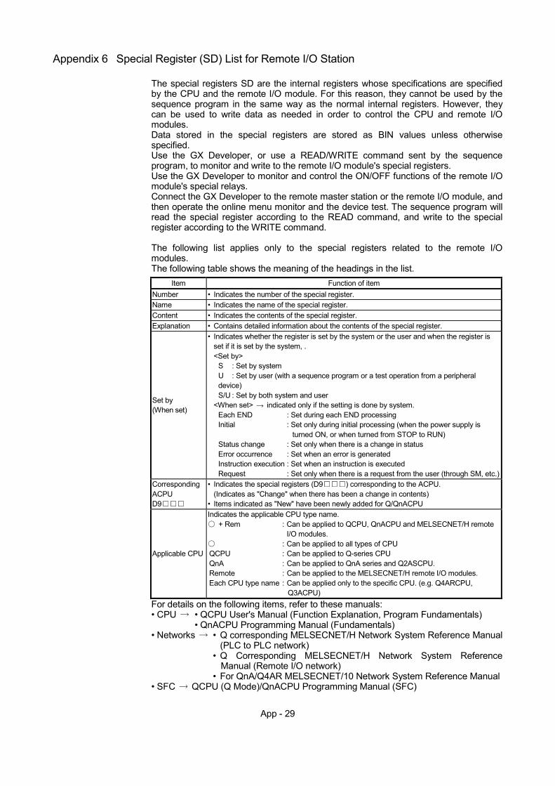
App - 29
Appendix 6 Special Register (SD) List for Remote I/O Station
The special registers SD are the internal registers whose specifications are specified by the CPU and the remote I/O module. For this reason, they cannot be used by the sequence program in the same way as the normal internal registers. However, they can be used to write data as needed in order to control the CPU and remote I/O modules. Data stored in the special registers are stored as BIN values unless otherwise specified. Use the GX Developer, or use a READ/WRITE command sent by the sequence program, to monitor and write to the remote I/O module's special registers. Use the GX Developer to monitor and control the ON/OFF functions of the remote I/O module's special relays. Connect the GX Developer to the remote master station or the remote I/O module, and then operate the online menu monitor and the device test. The sequence program will read the special register according to the READ command, and write to the special register according to the WRITE command.
The following list applies only to the special registers related to the remote I/O modules. The following table shows the meaning of the headings in the list.
Item Function of item
Number • Indicates the number of the special register. Name • Indicates the name of the special register. Content • Indicates the contents of the special register. Explanation • Contains detailed information about the contents of the special register.
Set by (When set)
• Indicates whether the register is set by the system or the user and when the register is set if it is set by the system, . <Set by>
S : Set by system U : Set by user (with a sequence program or a test operation from a peripheral device) S/U : Set by both system and user
<When set> indicated only if the setting is done by system. Each END : Set during each END processing Initial : Set only during initial processing (when the power supply is
turned ON, or when turned from STOP to RUN) Status change : Set only when there is a change in status Error occurrence : Set when an error is generated Instruction execution : Set when an instruction is executed Request : Set only when there is a request from the user (through SM, etc.)
Corresponding ACPU D9
• Indicates the special registers (D9 ) corresponding to the ACPU. (Indicates as "Change" when there has been a change in contents)
• Items indicated as "New" have been newly added for Q/QnACPU
Applicable CPU
Indicates the applicable CPU type name. + Rem : Can be applied to QCPU, QnACPU and MELSECNET/H remote
I/O modules. : Can be applied to all types of CPU
QCPU : Can be applied to Q-series CPU QnA : Can be applied to QnA series and Q2ASCPU. Remote : Can be applied to the MELSECNET/H remote I/O modules. Each CPU type name : Can be applied only to the specific CPU. (e.g. Q4ARCPU,
Q3ACPU) For details on the following items, refer to these manuals: • CPU • QCPU User's Manual (Function Explanation, Program Fundamentals)
• QnACPU Programming Manual (Fundamentals) • Networks • Q corresponding MELSECNET/H Network System Reference Manual
(PLC to PLC network) • Q Corresponding MELSECNET/H Network System Reference
Manual (Remote I/O network) • For QnA/Q4AR MELSECNET/10 Network System Reference Manual
• SFC QCPU (Q Mode)/QnACPU Programming Manual (SFC)
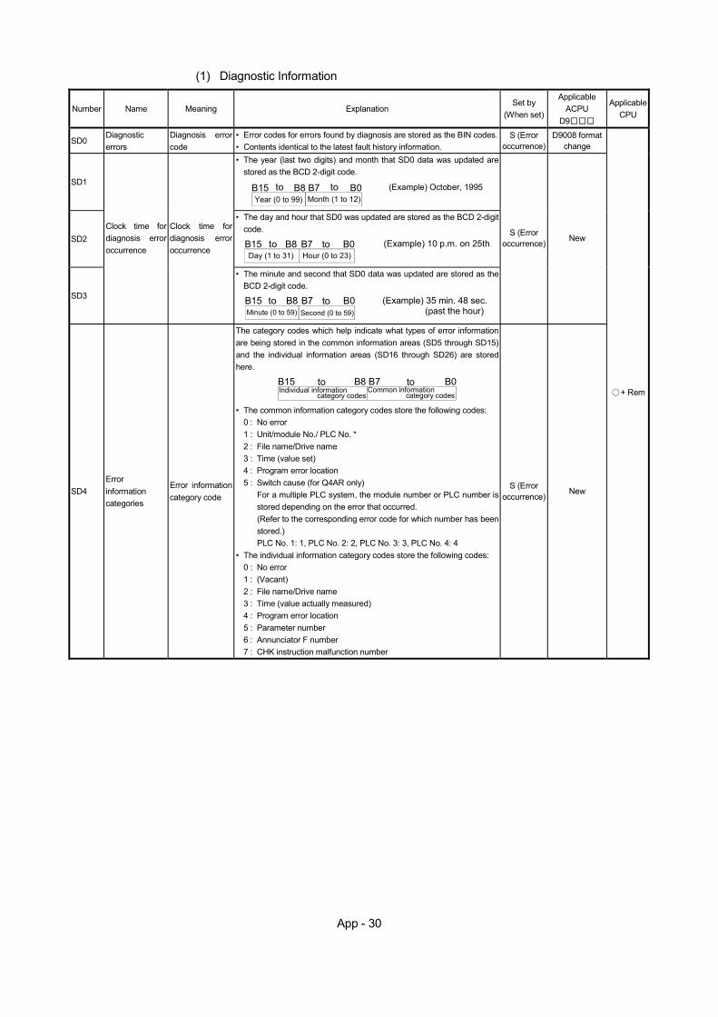
App - 30
(1) Diagnostic Information
Number Name Meaning Explanation Set by
(When set)
Applicable ACPU
D9
Applicable CPU
SD0 Diagnostic errors
Diagnosis error code
• Error codes for errors found by diagnosis are stored as the BIN codes.• Contents identical to the latest fault history information.
S (Error occurrence)
D9008 format change
SD1
• The year (last two digits) and month that SD0 data was updated arestored as the BCD 2-digit code.
Year (0 to 99) Month (1 to 12)B15 B7 B0B8to to (Example) October, 1995
SD2
• The day and hour that SD0 was updated are stored as the BCD 2-digit code.
Day (1 to 31) Hour (0 to 23)B15 B7 B0B8to to (Example) 10 p.m. on 25th
SD3
Clock time for diagnosis error occurrence
Clock time for diagnosis error occurrence
• The minute and second that SD0 data was updated are stored as the BCD 2-digit code.
Minute (0 to 59) Second (0 to 59)B15 B7 B0B8to to (Example) 35 min. 48 sec.
(past the hour)
S (Error occurrence) New
SD4 Error information categories
Error information category code
The category codes which help indicate what types of error information are being stored in the common information areas (SD5 through SD15) and the individual information areas (SD16 through SD26) are stored here.
Individual information Common informationB15 B7 B0B8to to
category codes category codes
• The common information category codes store the following codes: 0 : No error 1 : Unit/module No./ PLC No. * 2 : File name/Drive name 3 : Time (value set) 4 : Program error location 5 : Switch cause (for Q4AR only)
For a multiple PLC system, the module number or PLC number is stored depending on the error that occurred. (Refer to the corresponding error code for which number has been stored.) PLC No. 1: 1, PLC No. 2: 2, PLC No. 3: 3, PLC No. 4: 4
• The individual information category codes store the following codes: 0 : No error 1 : (Vacant) 2 : File name/Drive name 3 : Time (value actually measured) 4 : Program error location 5 : Parameter number 6 : Annunciator F number 7 : CHK instruction malfunction number
S (Error occurrence)
New
+ Rem
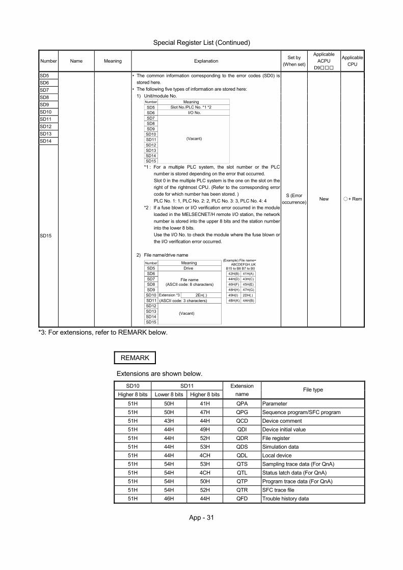
App - 31
Special Register List (Continued)
Number Name Meaning Explanation Set by
(When set)
Applicable ACPU
D9
Applicable CPU
SD5 SD6 SD7 SD8 SD9 SD10 SD11 SD12 SD13 SD14
SD15
• The common information corresponding to the error codes (SD0) is stored here.
• The following five types of information are stored here: 1) Unit/module No.
Number
SD5SD6SD7SD8SD9SD10SD11SD12SD13SD14SD15
MeaningSlot No./PLC No. *1 *2
I/O No.
(Vacant)
*1 : For a multiple PLC system, the slot number or the PLC number is stored depending on the error that occurred. Slot 0 in the multiple PLC system is the one on the slot on the right of the rightmost CPU. (Refer to the corresponding error code for which number has been stored. ) PLC No. 1: 1, PLC No. 2: 2, PLC No. 3: 3, PLC No. 4: 4
*2 : If a fuse blown or I/O verification error occurred in the module loaded in the MELSECNET/H remote I/O station, the network number is stored into the upper 8 bits and the station number into the lower 8 bits. Use the I/O No. to check the module where the fuse blown or the I/O verification error occurred.
2) File name/drive name
NumberSD5SD6SD7SD8SD9
SD10SD11SD12SD13SD14SD15
MeaningDrive
2EH(.)
File name(ASCII code: 8 characters)
Extension *3 (ASCII code: 3 characters)
(Vacant)
(Example) File name=ABCDEFGH.IJK
42H(B) 41H(A)44H(D) 43H(C)46H(F) 45H(E)48H(H) 47H(G)49H(I) 2DH(.)4BH(K) 4AH(B)
B15 to B8 B7 to B0
S (Error occurrence)
New + Rem
*3: For extensions, refer to REMARK below.
REMARK
Extensions are shown below.
SD10 SD11 Higher 8 bits Lower 8 bits Higher 8 bits
Extension name
File type
51H 50H 41H QPA Parameter 51H 50H 47H QPG Sequence program/SFC program 51H 43H 44H QCD Device comment 51H 44H 49H QDI Device initial value 51H 44H 52H QDR File register 51H 44H 53H QDS Simulation data 51H 44H 4CH QDL Local device 51H 54H 53H QTS Sampling trace data (For QnA) 51H 54H 4CH QTL Status latch data (For QnA) 51H 54H 50H QTP Program trace data (For QnA) 51H 54H 52H QTR SFC trace file 51H 46H 44H QFD Trouble history data
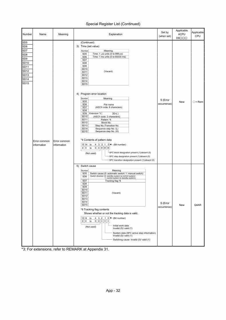
App - 32
Special Register List (Continued)
Number Name Meaning Explanation Set by
(when set)
Applicable ACPU
D9
Applicable CPU
SD5 SD6 SD7 SD8 SD9 SD10 SD11 SD12 SD13 SD14
(Continued) 3) Time (set value)
Number
SD5SD6SD7SD8SD9
SD10SD11SD12SD13SD14SD15
MeaningTime: 1 s units (0 to 999 s)
(Vacant)
Time: 1 ms units (0 to 65535 ms)
4) Program error location
NumberSD5SD6SD7SD8SD9SD10SD11SD12SD13SD14SD15
Meaning
2EH(.)
File name(ASCII code: 8 characters)
Extension *3(ASCII code: 3 characters)
Pattern *4Block No.
Step No./Transition No.Sequence step No. (L)Sequence step No. (H)
*4 Contents of pattern data
000 0 to0123415 14 to
(Not used)
(Bit number)
SFC block designation present (1)/absent (0)
SFC step designation present (1)/absent (0)
SFC transition designation present (1)/absent (0)
S (Error occurrence)
New + Rem
SD15
Error common information
Error common information
5) Switch cause NumberSD5SD6
SD7SD8SD9SD10SD11SD12SD13SD14SD15
MeaningSwitch cause (0: automatic switch/ 1: manual switch)
(Vacant)
Switch direction (0: standby system to control system/
Tracking flag *61: control system to standby system)
*6 Tracking flag contents Shows whether or not the tracking data is valid.
Initial work dataInvalid (0)/ valid (1)
000 0 to0123415 14 to
System data (SFC active step information)Invalid (0)/ valid (1)
Switching cause Invalid (0)/ valid (1)
(Not used)
(Bit number)
S (Error occurrence)
New Q4AR
*3: For extensions, refer to REMARK at Appendix 31.
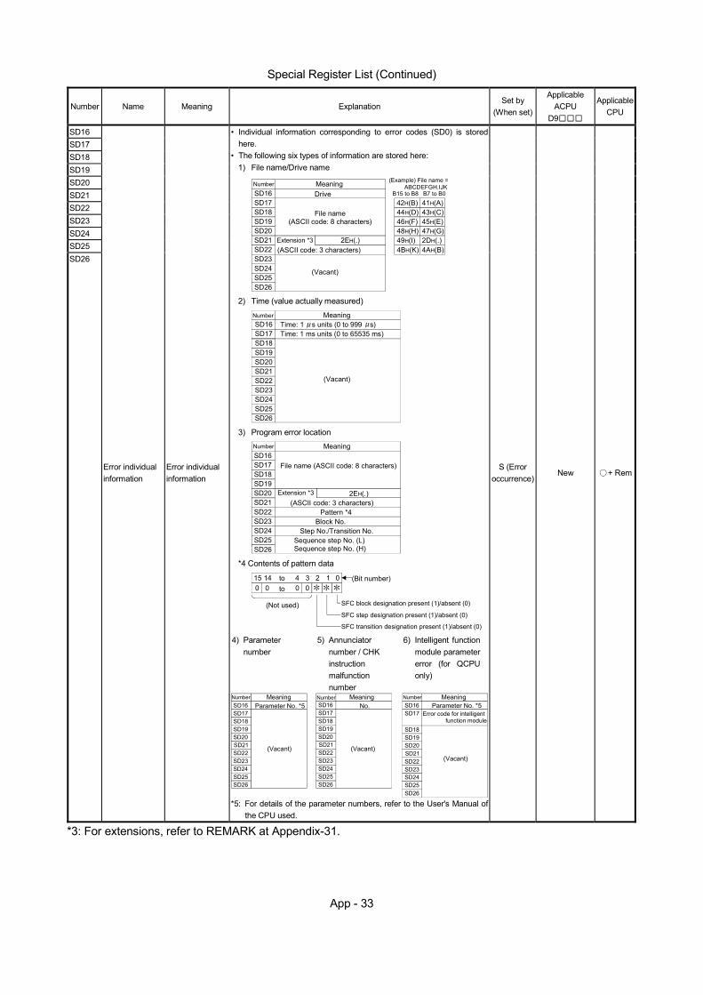
App - 33
Special Register List (Continued)
Number Name Meaning Explanation Set by
(When set)
Applicable ACPU
D9
Applicable CPU
SD16 SD17 SD18 SD19 SD20 SD21 SD22 SD23 SD24 SD25 SD26
Error individual information
Error individual information
• Individual information corresponding to error codes (SD0) is stored here.
• The following six types of information are stored here: 1) File name/Drive name
NumberSD16SD17SD18SD19SD20SD21SD22SD23SD24SD25SD26
MeaningDrive
2EH(.)
File name(ASCII code: 8 characters)
Extension *3(ASCII code: 3 characters)
(Vacant)
(Example) File name =ABCDEFGH.IJK
42H(B) 41H(A)44H(D) 43H(C)46H(F) 45H(E)48H(H) 47H(G)49H(I) 2DH(.)4BH(K) 4AH(B)
B15 to B8 B7 to B0
2) Time (value actually measured)
NumberSD16SD17SD18SD19SD20SD21SD22SD23SD24SD25SD26
MeaningTime: 1 s units (0 to 999 s)
(Vacant)
Time: 1 ms units (0 to 65535 ms)
3) Program error location NumberSD16SD17SD18SD19SD20SD21SD22SD23SD24SD25
Meaning
2EH(.)
File name (ASCII code: 8 characters)
Extension *3(ASCII code: 3 characters)
Pattern *4Block No.
Step No./Transition No.Sequence step No. (L)Sequence step No. (H)SD26
*4 Contents of pattern data
SFC block designation present (1)/absent (0)
000 0 to0123415 14 to
SFC step designation present (1)/absent (0)
SFC transition designation present (1)/absent (0)
(Not used)
(Bit number)
4) Parameter number
5) Annunciator number / CHK instruction malfunction number
6) Intelligent function module parameter error (for QCPU only)
NumberSD16SD17SD18SD19SD20SD21SD22SD23SD24SD25SD26
MeaningParameter No. *5
(Vacant)
SD16SD17SD18SD19SD20SD21SD22SD23SD24SD25SD26
No. SD16SD17
SD18SD19SD20SD21SD22SD23SD24SD25SD26
Error code for intelligent function module
Number NumberMeaning MeaningParameter No. *5
(Vacant)(Vacant)
*5: For details of the parameter numbers, refer to the User's Manual of the CPU used.
S (Error occurrence)
New + Rem
*3: For extensions, refer to REMARK at Appendix-31.

App - 34
Special Register List (Continued)
Number Name Meaning Explanation Set by
(when set)
Applicable ACPU
D9
Applicable CPU
SD50 Error reset Error number for error reset to be performed
• Stores the error number for which the error reset is performed U New + Rem
SD53 AC DOWN detection
Number of times for AC DOWN
• Each time the voltage falls below 85% of the rating (AC power/ 65% DC power) while the CPU module is calculating, it will be saved as a BIN code with 1 added to the value.
S (Error occurrence)
D9005 + Rem
SD60 Fuse blown number
Number of module with fuse blown
• Stores the smallest station I/O number of the module where a fuse blown has occurred.
S (Error occurrence)
D9000
SD61 I/O module verification error number
I/O module verification error module number
• Stores the smallest I/O number of the module where an I/O module verification error has occurred.
S (Error occurrence)
D9002
+ Rem
SD105
xCH1 transmission speed setting (RS232)
Stores the preset transmission speed when GX Developer is used.
K3: 300bps, K6: 600bps, K24: 2400bps, K48: 4800bps K96: 9600bps, K192: 19.2kbps, K384: 38.4kbps K576: 57.6kbps, K1152: 115.2kbps
S New
SD120 Error No. for external power supply OFF
Module No. which has external power supply error
• Stores the smallest head No. of the module whose external power supply is OFF.
* Applicable only for Q-series modules (For future use)
S (Error occurrence)
New
QCPU Rem
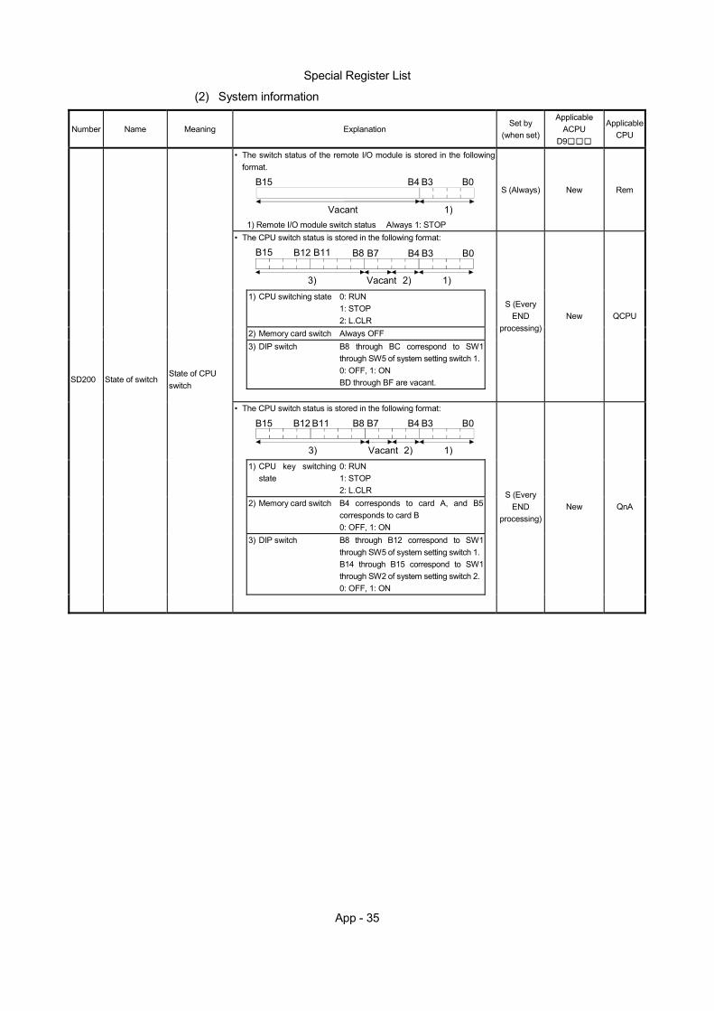
App - 35
Special Register List
(2) System information
Number Name Meaning Explanation Set by
(when set)
Applicable ACPU
D9
Applicable CPU
• The switch status of the remote I/O module is stored in the following format.
B15 B4 B3 B0
Vacant 1)
1) Remote I/O module switch status Always 1: STOP
S (Always) New Rem
• The CPU switch status is stored in the following format:
B15 B12 B11 B8 B7 B4 B3 B0
Vacant3) 2) 1)
1) CPU switching state 0: RUN 1: STOP 2: L.CLR
2) Memory card switch Always OFF 3) DIP switch B8 through BC correspond to SW1
through SW5 of system setting switch 1. 0: OFF, 1: ON BD through BF are vacant.
S (Every END
processing) New QCPU
• The CPU switch status is stored in the following format:
B15 B12 B11 B8 B7 B4 B3 B0
Vacant3) 2) 1)
1) CPU key switching state
0: RUN 1: STOP 2: L.CLR
2) Memory card switch B4 corresponds to card A, and B5 corresponds to card B 0: OFF, 1: ON
3) DIP switch B8 through B12 correspond to SW1 through SW5 of system setting switch 1. B14 through B15 correspond to SW1 through SW2 of system setting switch 2. 0: OFF, 1: ON
SD200 State of switch State of CPU switch
S (Every END
processing) New QnA
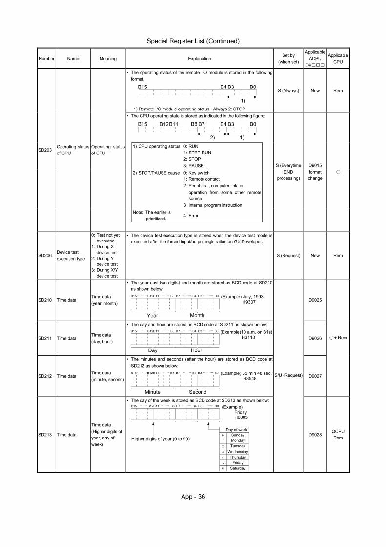
App - 36
Special Register List (Continued)
Number Name Meaning Explanation Set by
(when set)
ApplicableACPU
D9
Applicable CPU
• The operating status of the remote I/O module is stored in the following format.
B15 B4 B3 B0
1)
1) Remote I/O module operating status Always 2: STOP
S (Always) New Rem
• The CPU operating state is stored as indicated in the following figure:
B15 B12B11 B8 B7 B4 B3 B0
2) 1)
1) CPU operating status 0: RUN 1: STEP-RUN 2: STOP 3: PAUSE
2) STOP/PAUSE cause 0: Key switch 1: Remote contact 2: Peripheral, computer link, or
operation from some other remote source
3 Internal program instruction
Note: The earlier is prioritized.
4: Error
SD203 Operating status of CPU
Operating status of CPU
S (Everytime END
processing)
D9015 format change
SD206 Device test execution type
0: Test not yet executed
1: During X device test
2: During Y device test
3: During X/Y device test
• The device test execution type is stored when the device test mode is executed after the forced input/output registration on GX Developer.
S (Request) New Rem
SD210 Time data Time data (year, month)
• The year (last two digits) and month are stored as BCD code at SD210 as shown below: B15 B12B11 B8 B7 B4 B3 B0
Year Month
(Example) July, 1993 H9307
D9025
SD211 Time data Time data (day, hour)
• The day and hour are stored as BCD code at SD211 as shown below: B15 B12B11 B8 B7 B4 B3 B0
Day Hour
(Example)10 a.m. on 31st H3110 D9026
SD212 Time data Time data (minute, second)
• The minutes and seconds (after the hour) are stored as BCD code at SD212 as shown below:
(Example) 35 min 48 sec. H3548
B15 B12B11 B8 B7 B4 B3 B0
Minute Second
D9027
+ Rem
SD213 Time data
Time data (Higher digits of year, day of week)
• The day of the week is stored as BCD code at SD213 as shown below: B15 B12B11 B8 B7 B4 B3 B0
Higher digits of year (0 to 99)
Day of week0
1
2
3
4
56
SundayMondayTuesday
WednesdayThursday
FridaySaturday
(Example) Friday H0005
S/U (Request)
D9028 QCPU Rem
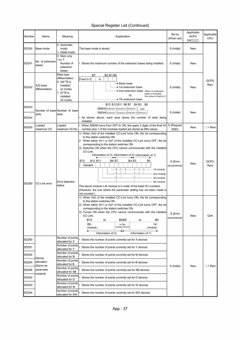
App - 37
Special Register List (Continued)
Number Name Meaning Explanation Set by
(When set)
Applicable ACPU
D9
Applicable CPU
SD240 Base mode 0: Automatic
mode 1: Detail mode
The base mode is stored. S (Initial) New
SD241 No. of extension bases
0: Main only 1 to 7:
Number of extension bases
• Stores the maximum number of the extension bases being installed. S (Initial) New
SD242 A/Q base differentiation
Base type differentiation 0: QA**B is
installed (A mode)
1: Q**B is installed (Q mode)
B0Fixed to 0
Basic base
B1B2B7
1st extension base2nd extension base
to7th extension base
to
When no extensionbase is mounted,the value is fixed to 0.
S (Initial) New
SD243
SD244
Number of base slots
Number of base slots
SM243 Extension 3 Main
SM244
B15 B12 B11 B8 B7 B4 B3 B0
Extension 7 Extension 6
Extension 2
Extension 5
Extension 1
Extension 4
• As shown above, each area stores the number of slots being installed.
S (Initial) New
QCPU Rem
SD250 Loaded maximum I/O
Loaded maximum I/O No.
• When SM250 turns from OFF to ON, the upper 2 digits of the final I/O number plus 1 of the modules loaded are stored as BIN values.
S (Request END)
New + Rem
1) When Xn0 of the installed CC-Link turns ON, the bit corresponding to the station switches ON.
2 When either Xn1 or XnF of the installed CC-Link turns OFF, the bit corresponding to the station switches ON.
3) Switches ON when the CPU cannot communicate with the installed CC-Link.
B0
1st module
B3B4B7B8B11B12B15Vacant
Information of 3) Information of 2) Information of 1)
2nd module
3rd module4th module
The above module n-th module is in order of the head I/O numbers. (However, the one where the parameter setting has not been made is not counted.)
S (Error occurrence)
New QCPU Rem
SD280 CC-Link error Error detection status
1) When Xn0 of the installed CC-Link turns ON, the bit corresponding to the station switches ON.
2) When either Xn1 or XnF of the installed CC-Link turns OFF, the bit corresponding to the station switches ON.
3) Turnss ON when the CPU cannot communicate with the installed CC-Link.
B15 B8B9 B08thmodule... module
1st...module
Information of 2)
toto
module1st 8th
Information of 1)
S (Error occurrence)
New QnA
SD290 Number of points allocated for X • Stores the number of points currently set for X devices
SD291 Number of points allocated for Y • Stores the number of points currently set for Y devices
SD292 Number of points allocated for M • Stores the number of points currently set for M devices
SD294 Number of points allocated for B • Stores the number of points currently set for B devices
SD296 Number of points allocated for SB • Stores the number of points currently set for SB devices
SD302 Number of points allocated for D • Stores the number of points currently set for D devices
SD303 Number of points allocated for W • Stores the number of points currently set for W devices
SD304
Device allocation (Same as parameter contents
Number of points allocated for SW • Stores the number of points currently set for SW devices
S (Initial) New + Rem
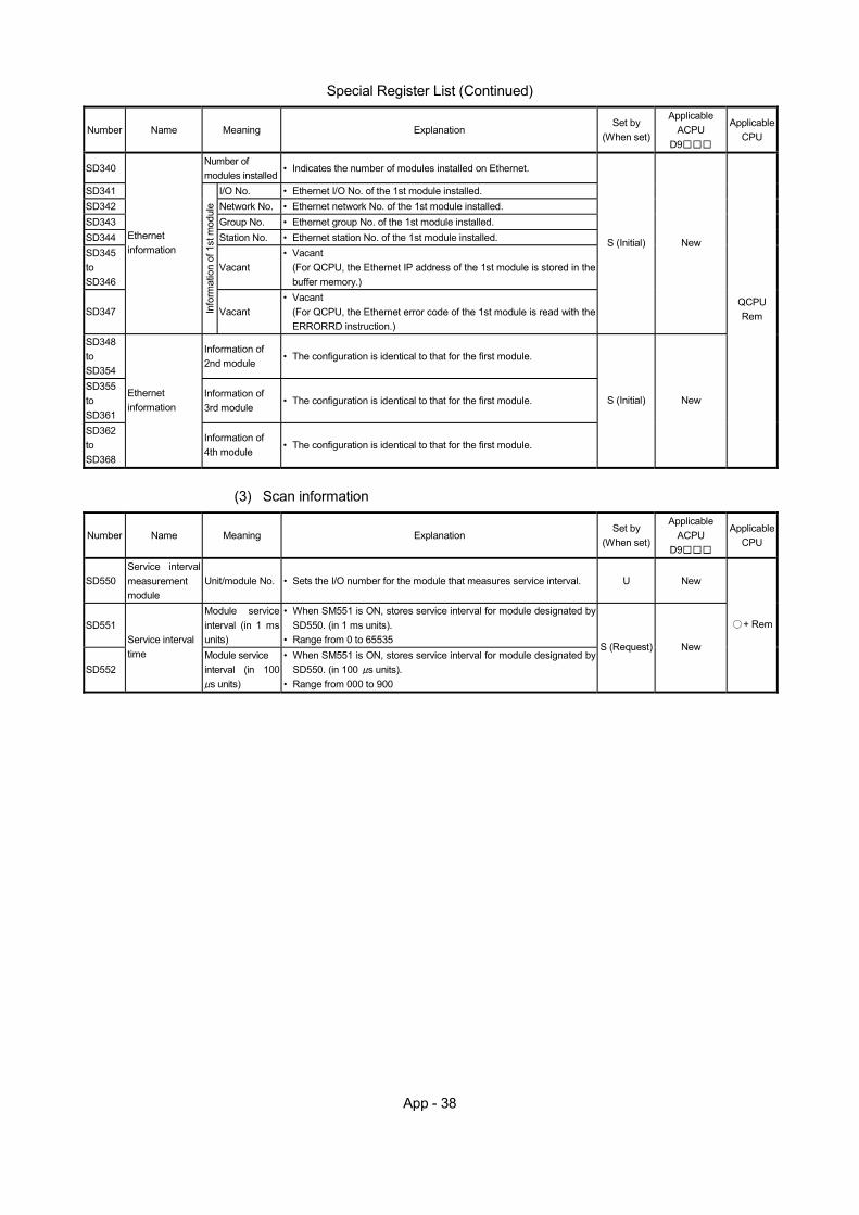
App - 38
Special Register List (Continued)
Number Name Meaning Explanation Set by
(When set)
Applicable ACPU
D9
Applicable CPU
SD340 Number of modules installed
• Indicates the number of modules installed on Ethernet.
SD341 I/O No. • Ethernet I/O No. of the 1st module installed. SD342 Network No. • Ethernet network No. of the 1st module installed. SD343 Group No. • Ethernet group No. of the 1st module installed. SD344 Station No. • Ethernet station No. of the 1st module installed. SD345 to SD346
Vacant • Vacant
(For QCPU, the Ethernet IP address of the 1st module is stored in the buffer memory.)
SD347
Ethernet information
Info
rmat
ion
of 1
st m
odul
e
Vacant • Vacant
(For QCPU, the Ethernet error code of the 1st module is read with the ERRORRD instruction.)
S (Initial) New
SD348 to SD354
Information of 2nd module
• The configuration is identical to that for the first module.
SD355 to SD361
Information of 3rd module
• The configuration is identical to that for the first module.
SD362 to SD368
Ethernet information
Information of 4th module
• The configuration is identical to that for the first module.
S (Initial) New
QCPU Rem
(3) Scan information
Number Name Meaning Explanation Set by
(When set)
Applicable ACPU
D9
Applicable CPU
SD550 Service interval measurement module
Unit/module No. • Sets the I/O number for the module that measures service interval. U New
SD551 Module service interval (in 1 ms units)
• When SM551 is ON, stores service interval for module designated by SD550. (in 1 ms units).
• Range from 0 to 65535
SD552
Service interval time Module service
interval (in 100 s units)
• When SM551 is ON, stores service interval for module designated by SD550. (in 100 s units).
• Range from 000 to 900
S (Request) New
+ Rem
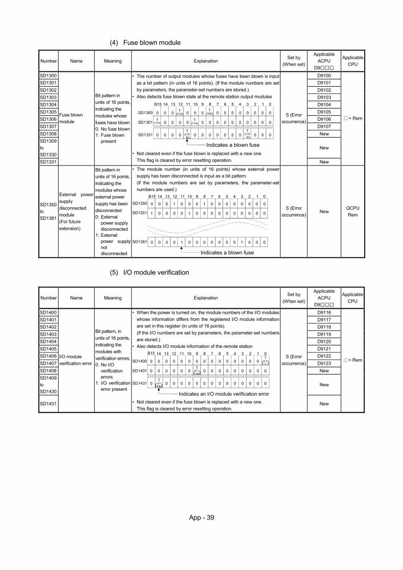
App - 39
(4) Fuse blown module
Number Name Meaning Explanation Set by
(When set)
Applicable ACPU
D9
Applicable CPU
SD1300 D9100 SD1301 D9101 SD1302 D9102 SD1303 D9103 SD1304 D9104 SD1305 D9105 SD1306 D9106 SD1307 D9107 SD1308 New SD1309 to SD1330
New
SD1331
Fuse blown module
Bit pattern in units of 16 points, indicating the modules whose fuses have blown 0: No fuse blown 1: Fuse blown
present
• The number of output modules whose fuses have been blown is input as a bit pattern (in units of 16 points). (If the module numbers are set by parameters, the parameter-set numbers are stored.)
• Also detects fuse blown state at the remote station output modules B15 14 13 12 11 10 9 8 7 6 5 4 3 2 1 0
0 0 0 1(YC0) 0 0 0 0 0 0 0 0 0 0 0
1(Y80)SD1300
0 01
(Y1F0) 0 0 0 0 0 0 0 0 0 01(Y1A)SD1301 0 0
0 01
(Y1F B0)
0 0 0 0 0 0 0 0SD1331 0 001
(Y1F 30)
0
Indicates a blown fuse
• Not cleared even if the fuse blown is replaced with a new one. This flag is cleared by error resetting operation.
S (Error occurrence)
New
+ Rem
SD1350 to SD1381
External power supply disconnected module (For future extension)
Bit pattern in units of 16 points, indicating the modules whose external power supply has been disconnected 0: External
power supply disconnected
1: External power supply not disconnected
• The module number (in units of 16 points) whose external power supply has been disconnected is input as a bit pattern. (If the module numbers are set by parameters, the parameter-set numbers are used.)
B15 14 13 12 11 10 9 8 7 6 5 4 3 2 1 0
0 0 0 1 0 0 0 0 0 0 0 0 0 0 01SD1350
0 01 0 0 0 0 0 0 0 0 0 01SD1351 0 0
0 0 1 0 0 0 0 0 0 0 0SD1381 0 00 10
Indicates a blown fuse
S (Error occurrence)
New QCPU Rem
(5) I/O module verification
Number Name Meaning Explanation Set by
(When set)
Applicable ACPU
D9
Applicable CPU
SD1400 D9116 SD1401 D9117 SD1402 D9118 SD1403 D9119 SD1404 D9120 SD1405 D9121 SD1406 D9122 SD1407 D9123 SD1408 New SD1409 to SD1430
New
SD1431
I/O module verification error
Bit pattern, in units of 16 points, indicating the modules with verification errors. 0: No I/O
verification errors
1: I/O verification error present
• When the power is turned on, the module numbers of the I/O modules whose information differs from the registered I/O module information are set in this register (in units of 16 points). (If the I/O numbers are set by parameters, the parameter-set numbers are stored.)
• Also detects I/O module information of the remote station B15 14 13 12 11 10 9 8 7 6 5 4 3 2 1 0
0 0 0 0 0 0 0 0 0 0 0 0 0SD1400
0 0 0 0 0 0 0 0 0 0 0SD1401 0 0
0 0 0 0 0 0 0 0 0SD1431 0 000
Indicates an I/O module verification error
0 0
00
001
( )X Y1FE0
X Y0
1( )X Y190
1( )
• Not cleared even if the fuse blown is replaced with a new one. This flag is cleared by error resetting operation.
S (Error occurrence)
New
+ Rem
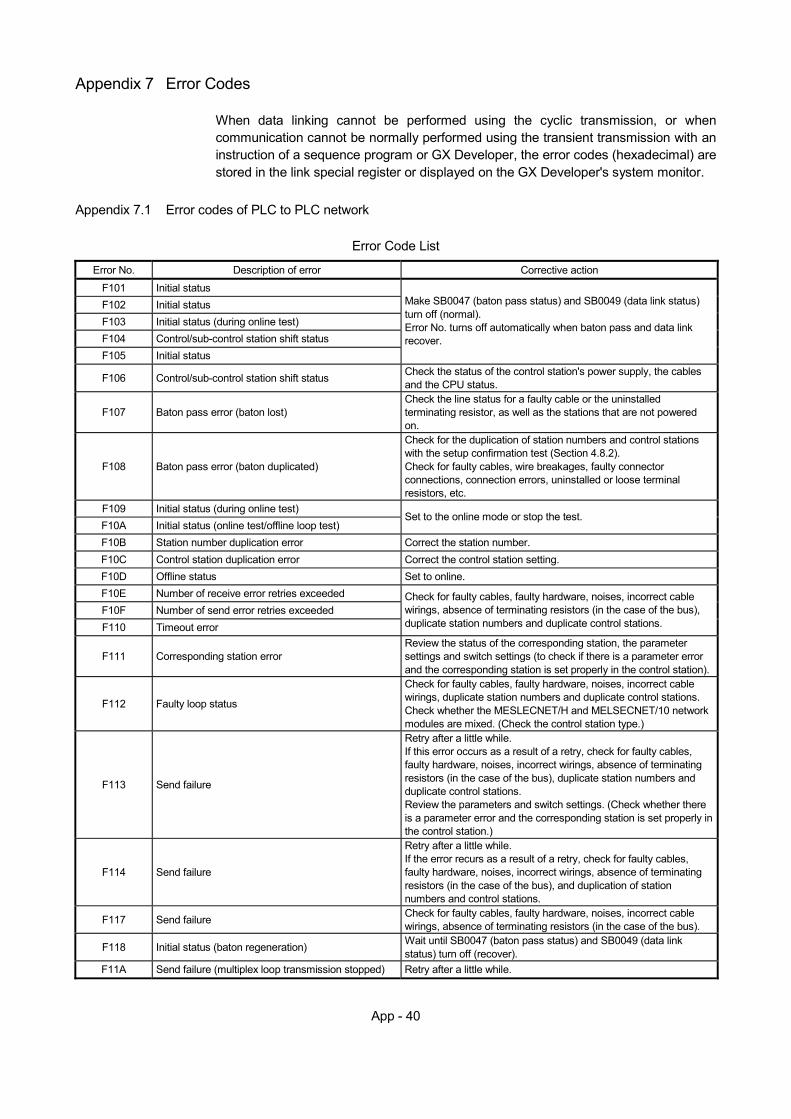
App - 40
Appendix 7 Error Codes
When data linking cannot be performed using the cyclic transmission, or when communication cannot be normally performed using the transient transmission with an instruction of a sequence program or GX Developer, the error codes (hexadecimal) are stored in the link special register or displayed on the GX Developer's system monitor.
Appendix 7.1 Error codes of PLC to PLC network
Error Code List
Error No. Description of error Corrective action
F101 Initial status F102 Initial status F103 Initial status (during online test) F104 Control/sub-control station shift status F105 Initial status
Make SB0047 (baton pass status) and SB0049 (data link status) turn off (normal). Error No. turns off automatically when baton pass and data link recover.
F106 Control/sub-control station shift status Check the status of the control station's power supply, the cables and the CPU status.
F107 Baton pass error (baton lost) Check the line status for a faulty cable or the uninstalled terminating resistor, as well as the stations that are not powered on.
F108 Baton pass error (baton duplicated)
Check for the duplication of station numbers and control stations with the setup confirmation test (Section 4.8.2). Check for faulty cables, wire breakages, faulty connector connections, connection errors, uninstalled or loose terminal resistors, etc.
F109 Initial status (during online test) F10A Initial status (online test/offline loop test)
Set to the online mode or stop the test.
F10B Station number duplication error Correct the station number. F10C Control station duplication error Correct the control station setting. F10D Offline status Set to online. F10E Number of receive error retries exceeded F10F Number of send error retries exceeded F110 Timeout error
Check for faulty cables, faulty hardware, noises, incorrect cable wirings, absence of terminating resistors (in the case of the bus), duplicate station numbers and duplicate control stations.
F111 Corresponding station error Review the status of the corresponding station, the parameter settings and switch settings (to check if there is a parameter error and the corresponding station is set properly in the control station).
F112 Faulty loop status
Check for faulty cables, faulty hardware, noises, incorrect cable wirings, duplicate station numbers and duplicate control stations. Check whether the MESLECNET/H and MELSECNET/10 network modules are mixed. (Check the control station type.)
F113 Send failure
Retry after a little while. If this error occurs as a result of a retry, check for faulty cables, faulty hardware, noises, incorrect wirings, absence of terminating resistors (in the case of the bus), duplicate station numbers and duplicate control stations. Review the parameters and switch settings. (Check whether there is a parameter error and the corresponding station is set properly in the control station.)
F114 Send failure
Retry after a little while. If the error recurs as a result of a retry, check for faulty cables, faulty hardware, noises, incorrect wirings, absence of terminating resistors (in the case of the bus), and duplication of station numbers and control stations.
F117 Send failure Check for faulty cables, faulty hardware, noises, incorrect cable wirings, absence of terminating resistors (in the case of the bus).
F118 Initial status (baton regeneration) Wait until SB0047 (baton pass status) and SB0049 (data link status) turn off (recover).
F11A Send failure (multiplex loop transmission stopped) Retry after a little while.
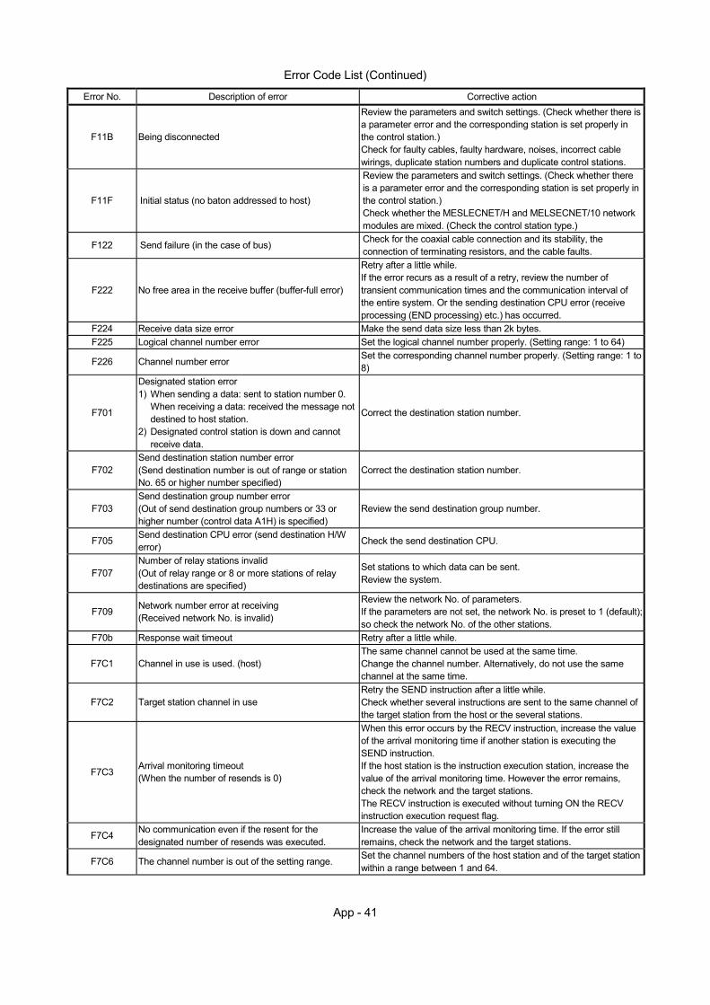
App - 41
Error Code List (Continued)
Error No. Description of error Corrective action
F11B Being disconnected
Review the parameters and switch settings. (Check whether there is a parameter error and the corresponding station is set properly in the control station.) Check for faulty cables, faulty hardware, noises, incorrect cable wirings, duplicate station numbers and duplicate control stations.
F11F Initial status (no baton addressed to host)
Review the parameters and switch settings. (Check whether there is a parameter error and the corresponding station is set properly in the control station.) Check whether the MESLECNET/H and MELSECNET/10 network modules are mixed. (Check the control station type.)
F122 Send failure (in the case of bus) Check for the coaxial cable connection and its stability, the connection of terminating resistors, and the cable faults.
F222 No free area in the receive buffer (buffer-full error)
Retry after a little while. If the error recurs as a result of a retry, review the number of transient communication times and the communication interval of the entire system. Or the sending destination CPU error (receive processing (END processing) etc.) has occurred.
F224 Receive data size error Make the send data size less than 2k bytes. F225 Logical channel number error Set the logical channel number properly. (Setting range: 1 to 64)
F226 Channel number error Set the corresponding channel number properly. (Setting range: 1 to 8)
F701
Designated station error 1) When sending a data: sent to station number 0.
When receiving a data: received the message not destined to host station.
2) Designated control station is down and cannot receive data.
Correct the destination station number.
F702 Send destination station number error (Send destination number is out of range or station No. 65 or higher number specified)
Correct the destination station number.
F703 Send destination group number error (Out of send destination group numbers or 33 or higher number (control data A1H) is specified)
Review the send destination group number.
F705 Send destination CPU error (send destination H/W error) Check the send destination CPU.
F707 Number of relay stations invalid (Out of relay range or 8 or more stations of relay destinations are specified)
Set stations to which data can be sent. Review the system.
F709 Network number error at receiving (Received network No. is invalid)
Review the network No. of parameters. If the parameters are not set, the network No. is preset to 1 (default); so check the network No. of the other stations.
F70b Response wait timeout Retry after a little while.
F7C1 Channel in use is used. (host) The same channel cannot be used at the same time. Change the channel number. Alternatively, do not use the same channel at the same time.
F7C2 Target station channel in use Retry the SEND instruction after a little while. Check whether several instructions are sent to the same channel of the target station from the host or the several stations.
F7C3 Arrival monitoring timeout (When the number of resends is 0)
When this error occurs by the RECV instruction, increase the value of the arrival monitoring time if another station is executing the SEND instruction. If the host station is the instruction execution station, increase the value of the arrival monitoring time. However the error remains, check the network and the target stations. The RECV instruction is executed without turning ON the RECV instruction execution request flag.
F7C4 No communication even if the resent for the designated number of resends was executed.
Increase the value of the arrival monitoring time. If the error still remains, check the network and the target stations.
F7C6 The channel number is out of the setting range. Set the channel numbers of the host station and of the target station within a range between 1 and 64.
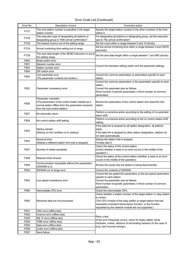
App - 42
Error Code List (Continued)
Error No. Description of error Corrective action
F7C7 The host station number is specified in the target station number.
Specify the target station number to the other numbers of the host station’s.
F7C8 The execution type of designating all stations or designating group is "With arrival confirmation".
For designating all stations or designating group, set the execution type to "No arrival confirmation".
F7C9 The resend count is out of the setting range. Set the count within a range between 0 and 15 (times).
F7CA Arrival monitoring time setting out of range Set the arrival monitoring time within a range between 0 and 32676 (seconds).
F7CB The sent data length of the SEND instruction is out of the setting range.
Set the sent data length within a range between 1 and 960 (words).
F800 Mode switch error F801 Network number error F803 Station number error F804 DIP switch error
Correct the hardware setting switch and the parameter settings.
F820 Link parameter error (The parameter contents are broken.)
Correct the common parameters or parameters specific to each station.
F823 Parameter consistency error
Correct the common parameters or the parameters specific to each station. Correct the parameter size as follows. Word number of specific parameters ≤ Word number of common parameters
F826
Parameter mismatch (The parameters of the control station started as a normal station differs from the parameters received from the sub-control station)
Review the parameters of the control station and reset the host station.
F827 No automatic return Perform a corrective action according to the setting of no automatic return shift.
F828 No control station shift setting Perform a corrective action according to the no control station shift setting.
F832 Startup denied (Startup on the condition of no startup)
If the data link is stopped by all station designation, all stations starts. If the data link is stopped by other station designation, stations do not start automatically.
F833 Keyword error (Started a different station from that is stopped)
Startup the station that is stopped. Forcibly start it.
F837 Number of retries exceeded Check the status of the control station. (Check whether a reset or an error occurs in the middle of the operation.)
F838 Relevant timer timeout Check the status of the control station (whether a reset or an error occurs in the middle of the operation)
F839 Communication impossible without link parameters (SW0056 is 0) Review the cause why the station is being disconnected.
F83A SW0000 out of range error Correct the contents of SW0000.
F842 Low speed consistency error
Correct the low speed link parameters or the low speed parameters specific to each station Correct the parameter size as follows. Word number of specific parameters ≤ Word number of common parameters
F906 Intermediate CPU error Check the intermediate CPU.
F982 Received data are not processed.
Check whether a station number of the target station or relay station is correct. (The CPU module of the relay station or target station that has requested a transient transmission function, or the function requested by the network module are not supported.)
FD01 CRC error (offline test) FD02 Overrun error (offline test) FD03 AB. IF error (offline test) FD04 TIME error (offline test) FD05 Data error (offline test) FD06 Under error (offline test) FD07 Send failure
Retry a test. (If the error frequently occurs, check for faulty cables, faulty hardware, noises, absence of terminating resistors (in the case of bus), and incorrect wirings.)
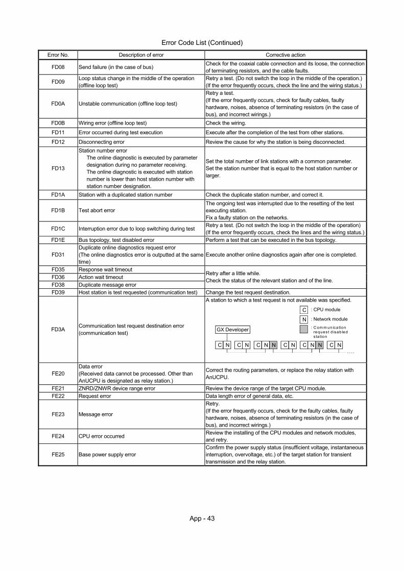
App - 43
Error Code List (Continued)
Error No. Description of error Corrective action
FD08 Send failure (in the case of bus) Check for the coaxial cable connection and its loose, the connection of terminating resistors, and the cable faults.
FD09 Loop status change in the middle of the operation (offline loop test)
Retry a test. (Do not switch the loop in the middle of the operation.) (If the error frequently occurs, check the line and the wiring status.)
FD0A Unstable communication (offline loop test)
Retry a test. (If the error frequently occurs, check for faulty cables, faulty hardware, noises, absence of terminating resistors (in the case of bus), and incorrect wirings.)
FD0B Wiring error (offline loop test) Check the wiring.
FD11 Error occurred during test execution Execute after the completion of the test from other stations.
FD12 Disconnecting error Review the cause for why the station is being disconnected.
FD13
Station number error The online diagnostic is executed by parameter designation during no parameter receiving. The online diagnostic is executed with station number is lower than host station number with station number designation.
Set the total number of link stations with a common parameter. Set the station number that is equal to the host station number or larger.
FD1A Station with a duplicated station number Check the duplicate station number, and correct it.
FD1B Test abort error The ongoing test was interrupted due to the resetting of the test executing station. Fix a faulty station on the networks.
FD1C Interruption error due to loop switching during test Retry a test. (Do not switch the loop in the middle of the operation) (If the error frequently occurs, check the lines and the wiring status.)
FD1E Bus topology, test disabled error Perform a test that can be executed in the bus topology.
FD31 Duplicate online diagnostics request error (The online diagnostics error is outputted at the same time)
Execute another online diagnostics again after one is completed.
FD35 Response wait timeout FD36 Action wait timeout FD38 Duplicate message error
Retry after a little while. Check the status of the relevant station and of the line.
FD39 Host station is test requested (communication test) Change the test request destination.
FD3A Communication test request destination error (communication test)
A station to which a test request is not available was specified.
C
N
C C C C C CN N N N N N N N
: CPU module
: Network module
: C om m un ica tion reques t d isab led sta tion
GX Developer
FE20 Data error (Received data cannot be processed. Other than AnUCPU is designated as relay station.)
Correct the routing parameters, or replace the relay station with AnUCPU.
FE21 ZNRD/ZNWR device range error Review the device range of the target CPU module. FE22 Request error Data length error of general data, etc.
FE23 Message error
Retry. (If the error frequently occurs, check for the faulty cables, faulty hardware, noises, absence of terminating resistors (in the case of bus), and incorrect wirings.)
FE24 CPU error occurred Review the installing of the CPU modules and network modules, and retry.
FE25 Base power supply error Confirm the power supply status (insufficient voltage, instantaneous interruption, overvoltage, etc.) of the target station for transient transmission and the relay station.
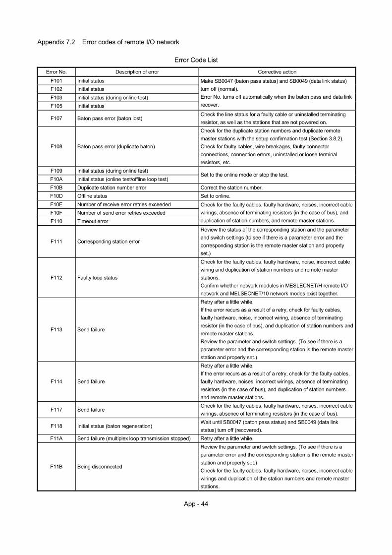
App - 44
Appendix 7.2 Error codes of remote I/O network
Error Code List
Error No. Description of error Corrective action
F101 Initial status F102 Initial status F103 Initial status (during online test) F105 Initial status
Make SB0047 (baton pass status) and SB0049 (data link status) turn off (normal). Error No. turns off automatically when the baton pass and data link recover.
F107 Baton pass error (baton lost) Check the line status for a faulty cable or uninstalled terminating resistor, as well as the stations that are not powered on.
F108 Baton pass error (duplicate baton)
Check for the duplicate station numbers and duplicate remote master stations with the setup confirmation test (Section 3.8.2). Check for faulty cables, wire breakages, faulty connector connections, connection errors, uninstalled or loose terminal resistors, etc.
F109 Initial status (during online test) F10A Initial status (online test/offline loop test)
Set to the online mode or stop the test.
F10B Duplicate station number error Correct the station number. F10D Offline status Set to online. F10E Number of receive error retries exceeded F10F Number of send error retries exceeded F110 Timeout error
Check for the faulty cables, faulty hardware, noises, incorrect cable wirings, absence of terminating resistors (in the case of bus), and duplication of station numbers, and remote master stations.
F111 Corresponding station error
Review the status of the corresponding station and the parameter and switch settings (to see if there is a parameter error and the corresponding station is the remote master station and properly set.)
F112 Faulty loop status
Check for the faulty cables, faulty hardware, noise, incorrect cable wiring and duplication of station numbers and remote master stations. Confirm whether network modules in MESLECNET/H remote I/O network and MELSECNET/10 network modes exist together.
F113 Send failure
Retry after a little while. If the error recurs as a result of a retry, check for faulty cables, faulty hardware, noise, incorrect wiring, absence of terminating resistor (in the case of bus), and duplication of station numbers and remote master stations. Review the parameter and switch settings. (To see if there is a parameter error and the corresponding station is the remote master station and properly set.)
F114 Send failure
Retry after a little while. If the error recurs as a result of a retry, check for the faulty cables, faulty hardware, noises, incorrect wirings, absence of terminating resistors (in the case of bus), and duplication of station numbers and remote master stations.
F117 Send failure Check for the faulty cables, faulty hardware, noises, incorrect cable wirings, absence of terminating resistors (in the case of bus).
F118 Initial status (baton regeneration) Wait until SB0047 (baton pass status) and SB0049 (data link status) turn off (recovered).
F11A Send failure (multiplex loop transmission stopped) Retry after a little while.
F11B Being disconnected
Review the parameter and switch settings. (To see if there is a parameter error and the corresponding station is the remote master station and properly set.) Check for the faulty cables, faulty hardware, noises, incorrect cable wirings and duplication of the station numbers and remote master stations.
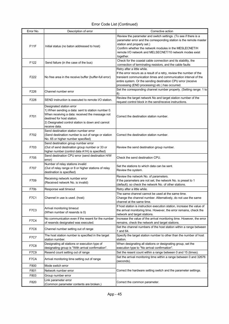
App - 45
Error Code List (Continued)
Error No. Description of error Corrective action
F11F Initial status (no baton addressed to host)
Review the parameter and switch settings. (To see if there is a parameter error and the corresponding station is the remote master station and properly set.) Confirm whether the network modules in the MESLECNET/H remote I/O network and MELSECNET/10 network modes exist together.
F122 Send failure (in the case of the bus) Check for the coaxial cable connection and its stability, the connection of terminating resistors, and the cable faults
F222 No free area in the receive buffer (buffer-full error)
Retry after a little while. If the error recurs as a result of a retry, review the number of the transient communication times and communication interval of the entire system. Or the sending destination CPU error (receive processing (END processing) etc.) has occurred.
F226 Channel number error Set the corresponding channel number properly. (Setting range: 1 to 8)
F228 SEND instruction is executed to remote I/O station. Review the target network No and target station number of the request control block in the send/receive instructions.
F701
Designated station error 1) When sending a data: sent to station number 0. When receiving a data: received the message not destined for host station. 2) Designated control station is down and cannot receive data.
Correct the destination station number.
F702 Send destination station number error (Send destination number is out of range or station No. 65 or higher number specified)
Correct the destination station number.
F703 Send destination group number error (Out of send destination group number or 33 or higher number (control data A1H) is specified)
Review the send destination group number.
F705 Send destination CPU error (send destination H/W error)
Check the send destination CPU.
F707 Number of relay stations invalid (Out of relay range or 8 or higher stations of relay destination is specified)
Set the stations to which data can be sent. Review the system.
F709 Receiving network number error (Received network No. is invalid)
Review the network No. of parameters. If the parameters are not set, the network No. is preset to 1 (default); so check the network No. of other stations.
F70b Response wait timeout Retry after a little while.
F7C1 Channel in use is used. (host) The same channel cannot be used at the same time. Change the channel number. Alternatively, do not use the same channel at the same time.
F7C3 Arrival monitoring timeout (When number of resends is 0)
If host station is instruction execution station, increase the value of the arrival monitoring time. However, the error remains, check the network and target stations.
F7C4 No communication even if the resent for the number of resends designated was executed.
Increase the value of the arrival monitoring time. However, the error remains, check the network and target stations.
F7C6 Channel number setting out of range Set the channel numbers of the host station within a range between 1 and 64.
F7C7 The host station number is specified in the target station number.
Specify the target station number to other than the number of host station.
F7C8 Designating all stations or execution type of designating group is "With arrival confirmation".
When designating all stations or designating group, set the execution type to "No arrival confirmation".
F7C9 Resend count setting out of range Set the resent count within a range between 0 and 15 (times).
F7CA Arrival monitoring time setting out of range Set the arrival monitoring time within a range between 0 and 32676 (seconds).
F800 Mode switch error F801 Network number error F803 Group number error
Correct the hardware setting switch and the parameter settings.
F820 Link parameter error (Common parameter contents are broken.)
Correct the common parameter.

App - 46
Error Code List (Continued)
Error No. Description of error Corrective action
F832 Startup denied (Startup on condition of no startup)
If the data link is stopped under all stations designation, start all stations. If the data link is stopped under other stations designation, the automatic start is denied.
F833 Keyword error (Startup on the station that is not station stopped)
Startup on the station that is station stopped. Forcibly start it.
F837 Exceeded number of retries Check the status of the remote master station. (Check whether resetting or an error occurs in the middle of the operation)
F838 Relevant timer timeout Check the status of the remote master station (to see if resetting or an error occurs in the middle of the operation)
F839 Communication impossible without link parameter (SW0056 is 0)
Review the cause for why the station is being disconnected.
F83A SW0000 out of range error Correct the contents of SW0000. F906 Intermediate CPU error Check the intermediate CPU.
F982 Receiving data that cannot be processed
Check whether the station number of the target station or relay station is correct. (The CPU module of relay station or target station that requested transient transmission function, or the function requested with network module are not supported.)
FD01 CRC error (offline test) FD02 Overrun error (offline test) FD03 AB. IF error (offline test) FD04 TIME error (offline test) FD05 Data error (offline test) FD06 Under error (offline test) FD07 Send failure
Retry a test. (If the error frequently occurs, check for the faulty cables, faulty hardware, noises, absence of terminating resistors (in the case of the bus), and incorrect wirings.)
FD08 Send failure (in the case of bus) Check for the coaxial cable connection and its stability, the connection of terminating resistors, and the cable faults
FD09 Loop status changed in the middle of the operation (offline loop test)
Retry a test. (Do not switch the loop in the middle of the operation) (If the error frequently occurs, check the line and the wiring status.)
FD0A Unstable communication (offline loop test)
Retry a test. (If the error frequently occurs, check for the faulty cables, faulty hardware, noises, absence of terminating resistosr (in the case of bus), and incorrect wirings.)
FD0B Wiring error (offline loop test) Check the wirings. FD11 Error occurred during test execution Execute after the completion of the test from other stations. FD12 Disconnecting error Review the cause for why the station is being disconnected.
FD1A Station with duplicated station number Check the duplicate station number, and correct it.
FD1B Test abort error The ongoing test was interrupted due to the resetting of the test executing station. Fix a faulty station on the networks.
FD1C Interruption error due to loop switching during test Retry a test. (Do not switch the loop in the middle of the operation) (If the error frequently occurs, check the line and the wiring status.)
FD1E Bus topology, test disabled error Perform a test that can be executed in the bus topology.
FD31 Duplicate online diagnostics request error (Online diagnostics error is outputted at the same time)
Execute the online diagnostics again after another is completed.
FD35 Response wait timeout FD36 Action wait time-out occurred FD38 Duplicate message error
Retry after a little while. Check the status of the relevant station and of the line.
FD39 Host station is test requested (communication test) Change the test request destination.
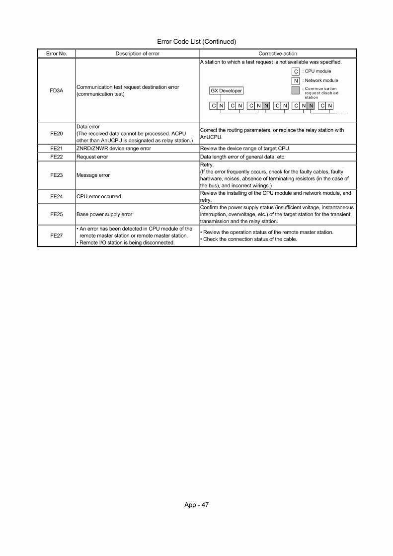
App - 47
Error Code List (Continued)
Error No. Description of error Corrective action
FD3A Communication test request destination error (communication test)
A station to which a test request is not available was specified.
C
N
C C C C C CN N N N N N N N
: CPU module
: Network module
: C om m un ica tion reques t d isab led sta tion
GX Developer
FE20 Data error (The received data cannot be processed. ACPU other than AnUCPU is designated as relay station.)
Correct the routing parameters, or replace the relay station with AnUCPU.
FE21 ZNRD/ZNWR device range error Review the device range of target CPU. FE22 Request error Data length error of general data, etc.
FE23 Message error
Retry. (If the error frequently occurs, check for the faulty cables, faulty hardware, noises, absence of terminating resistors (in the case of the bus), and incorrect wirings.)
FE24 CPU error occurred Review the installing of the CPU module and network module, and retry.
FE25 Base power supply error Confirm the power supply status (insufficient voltage, instantaneous interruption, overvoltage, etc.) of the target station for the transient transmission and the relay station.
FE27 • An error has been detected in CPU module of the
remote master station or remote master station. • Remote I/O station is being disconnected.
• Review the operation status of the remote master station. • Check the connection status of the cable.
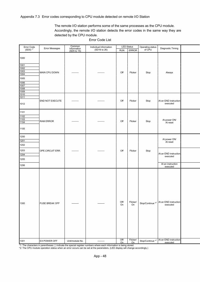
App - 48
Appendix 7.3 Error codes corresponding to CPU module detected on remote I/O Station
The remote I/O station performs some of the same processes as the CPU module. Accordingly, the remote I/O station detects the error codes in the same way they are detected by the CPU module.
Error Code List
LED Status Error Code (SD0) *1 Error Messages
Common Information (SD5 to 15)
Individual Information (SD16 to 26) RUN ERROR
Operating status of CPU Diagnostic Timing
1000
1001 1002 1003 1004
1005
1006 1007 1008 1009
MAIN CPU DOWN ——— ——— Off Flicker Stop Always
1010 1011
1012 END NOT EXECUTE ——— ——— Off Flicker Stop At an END instruction
executed
1101
1102 1103 1104
1105
RAM ERROR ——— ——— Off Flicker Stop At power ON/ At reset
1200
1201
1202
At power ON/ At reset
1203
1204
1205
At an END instruction executed
1206
OPE.CIRCUIT ERR. ——— ——— Off Flicker Stop
At an instruction executed
1300 FUSE BREAK OFF ——— ——— Off/ On
Flicker/ On Stop/Continue *2 At an END instruction
executed
1301 EX POWER OFF Unit/module No. ——— Off/ On
Flicker/ On Stop/Continue *2 At an END instruction
executed
*1: The characters in parentheses ( ) indicate the special register numbers where each information is being stored. *2: The CPU module operation status when an error occurs can be set at the parameters. (LED display will change accordingly.)
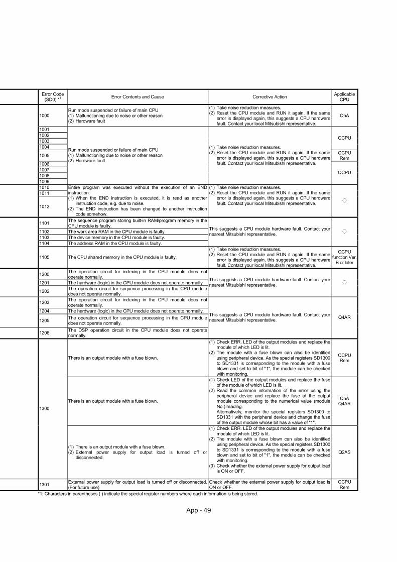
App - 49
Error Code (SD0) *1 Error Contents and Cause Corrective Action Applicable
CPU
1000 Run mode suspended or failure of main CPU (1) Malfunctioning due to noise or other reason (2) Hardware fault
(1) Take noise reduction measures. (2) Reset the CPU module and RUN it again. If the same
error is displayed again, this suggests a CPU hardware fault. Contact your local Mitsubishi representative.
QnA
1001 1002 1003 1004
QCPU
1005 QCPU Rem
1006 1007 1008 1009
Run mode suspended or failure of main CPU (1) Malfunctioning due to noise or other reason (2) Hardware fault
(1) Take noise reduction measures. (2) Reset the CPU module and RUN it again. If the same
error is displayed again, this suggests a CPU hardware fault. Contact your local Mitsubishi representative.
QCPU
1010 1011
1012
Entire program was executed without the execution of an END instruction. (1) When the END instruction is executed, it is read as another
instruction code, e.g. due to noise. (2) The END instruction has been changed to another instruction
code somehow.
(1) Take noise reduction measures. (2) Reset the CPU module and RUN it again. If the same
error is displayed again, this suggests a CPU hardware fault. Contact your local Mitsubishi representative.
1101 The sequence program storing built-in RAM/program memory in the CPU module is faulty.
1102 The work area RAM in the CPU module is faulty. 1103 The device memory in the CPU module is faulty.
1104 The address RAM in the CPU module is faulty.
This suggests a CPU module hardware fault. Contact your nearest Mitsubishi representative.
1105 The CPU shared memory in the CPU module is faulty.
(1) Take noise reduction measures. (2) Reset the CPU module and RUN it again. If the same
error is displayed again, this suggests a CPU hardware fault. Contact your local Mitsubishi representative.
QCPU function Ver.
B or later
1200 The operation circuit for indexing in the CPU module does not operate normally.
1201 The hardware (logic) in the CPU module does not operate normally. 1202 The operation circuit for sequence processing in the CPU module
does not operate normally.
This suggests a CPU module hardware fault. Contact your nearest Mitsubishi representative.
1203 The operation circuit for indexing in the CPU module does not operate normally.
1204 The hardware (logic) in the CPU module does not operate normally.
1205 The operation circuit for sequence processing in the CPU module does not operate normally.
1206 The DSP operation circuit in the CPU module does not operate normally.
This suggests a CPU module hardware fault. Contact your nearest Mitsubishi representative. Q4AR
There is an output module with a fuse blown.
(1) Check ERR. LED of the output modules and replace the module of which LED is lit.
(2) The module with a fuse blown can also be identified using peripheral device. As the special registers SD1300 to SD1331 is corresponding to the module with a fuse blown and set to bit of "1", the module can be checked with monitoring.
QCPU Rem
There is an output module with a fuse blown.
(1) Check LED of the output modules and replace the fuse of the module of which LED is lit.
(2) Read the common information of the error using the peripheral device and replace the fuse at the output module corresponding to the numerical value (module No.) reading. Alternatively, monitor the special registers SD1300 to SD1331 with the peripheral device and change the fuse of the output module whose bit has a value of "1".
QnA Q4AR
1300
(1) There is an output module with a fuse blown. (2) External power supply for output load is turned off or
disconnected.
(1) Check ERR. LED of the output modules and replace the module of which LED is lit.
(2) The module with a fuse blown can also be identified using peripheral device. As the special registers SD1300 to SD1331 is corresponding to the module with a fuse blown and set to bit of "1", the module can be checked with monitoring.
(3) Check whether the external power supply for output load is ON or OFF.
Q2AS
1301 External power supply for output load is turned off or disconnected. (For future use)
Check whether the external power supply for output load is ON or OFF.
QCPU Rem
*1: Characters in parentheses ( ) indicate the special register numbers where each information is being stored.
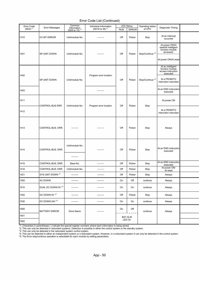
App - 50
Error Code List (Continued)
LED Status Error Code (SD0) *1 Error Messages
Common Information
(SD5 to 15) *1
Individual Information (SD16 to 26) *1 RUN ERROR
Operating status of CPU Diagnostic Timing
1310 I/O INT ERROR Unit/module No. ——— Off Flicker Stop At an interrupt occurred
At power ON/At reset/At intelligent function module
accessed. 1401 SP.UNIT DOWN Unit/module No. ——— Off Flicker Stop/Continue *5
At power ON/At reset
At an intelligent function module
access instruction executed
1402 Program error location At a FROM/TO
instruction executed
1403
SP.UNIT DOWN Unit/module No.
———
Off Flicker Stop/Continue *5
At an END instructionexecuted
1411 At power ON
1412
CONTROL-BUS ERR. Unit/module No. Program error location Off Flicker Stop
At a FROM/TO instruction executed
1413 CONTROL-BUS. ERR. ——— ——— Off Flicker Stop Always
Unit/module No.
1414 CONTROL-BUS. ERR.
———
——— Off Flicker Stop At an END instruction executed
1415 CONTROL-BUS. ERR. Base No. ——— Off Flicker Stop At an END instruction executed
1416 CONTROL-BUS. ERR. Unit/module No. ——— Off Flicker Stop At power ON/ At reset
1421 SYS.UNIT DOWN *3 ——— ——— Off Flicker Stop Always
1500 AC DOWN ——— ——— On Off continue Always
1510 DUAL DC DOWN 5V *3 ——— ——— On On continue Always
1520 DC DOWN 5V *4 ——— ——— Off Flicker Stop Always
1530 DC DOWN 24V *2 ——— ——— On On continue Always
1600 On Off
1601
1602
BATTERY ERROR Drive Name ———
BAT.ALM LED On
continue Always
*1: Characters in parentheses ( ) indicate the special register numbers where each information is being stored. *2: This can only be detected in redundant systems. Detection is possible in either the control system or the standby system. *3: This can only be detected in the redundant system control system. *4: This can be detected in either an independent system or a redundant system. However, in a redundant system it can only be detected in the control system. *5: The Error stop/continue operation is selectable for each module by setting parameters.

App - 51
Error Code (SD0) *1 Error Contents and Cause Corrective Action Applicable
CPU
1310 An interruption has occurred although there is no interrupt module.
This suggests a hardware fault for any of the mounted modules. Therefore, check the mounted modules and change the faulty module. Contact your nearest Mitsubishi representative.
• There was no response from the intelligent function module at initial updated.
• The size of the buffer memory of the intelligent function module is wrong.
This suggests a CPU module hardware fault. Contact your nearest Mitsubishi representative.
QCPU Rem
1401 When parameter I/O allocation was being made, there was no return signal from the special function module at initial communication. When error is generated, the head I/O number of the special function module that corresponds to the common information is stored.
This suggests a hardware fault for the special function module that was accessed. Contact your nearest Mitsubishi representative.
QnA
The intelligent function module was accessed in the program, but there was no response.
This suggests a CPU module hardware fault. Contact your nearest Mitsubishi representative.
QCPU Rem
1402 The special function module was accessed at the execution of a FROM/TO instruction set, but there was no response. When an error is generated, the program error location corresponding to the individual information is stored.
This suggests a hardware fault for the special function module that was accessed. Contact your nearest Mitsubishi representative.
QnA
1403
• There was no response from the intelligent function module when the END instruction is executed.
• An error occurrence was detected at the intelligent function module.
This suggests a hardware fault for the special function module that was accessed. Contact your nearest Mitsubishi representative.
QCPU Rem
1411
When performing a parameter I/O allocation, the special function module could not be accessed during initial communications. When error is generated, the head I/O number of the special function module that corresponds to the common information is stored.
Rem
1412
The FROM/TO instruction set could not be executed, due to a system bus error with the special function module. When an error is generated, the program error location corresponding to the individual information is stored.
This suggests an error for the special function module, CPU module or base module. Contact your nearest Mitsubishi representative.
The QCPU of function version A is mounted.
(1) Remove the QCPU of function version A from the base module.
(2) This suggests an error for the intelligent function module, CPU module or base module. Contact your nearest Mitsubishi representative.
QCPU function Ver.
B or later
1413
An error was detected on the Q bus. • Weight length timeout, arbitration timeout
This suggests an error for the special function module, CPU module or base module. Contact your nearest Mitsubishi representative.
QCPU Rem
Fault of the mounted module was detected. The QCPU of function version A is mounted.
(1) Remove the QCPU of function version A from the base module.
(2) This suggests an error for the intelligent function module, CPU module or base module. Contact your nearest Mitsubishi representative.
QCPU function Ver.
B or later
1414
An error was detected on the Q bus. This suggests an error for the special function module, CPU module or base module. Contact your nearest Mitsubishi representative.
QCPU Rem
1415 Fault of the main and extension base module was detected.
1416 A bus fault was detected at power-on or reset.
This suggests an error for the intelligent function module, CPU module or base module. Contact your nearest Mitsubishi representative.
QCPU function Ver.
B or later
1421 Hardware fault at the system management module AS92R. This suggests a hardware fault. Contact your nearest
Mitsubishi representative. Q4AR
1500 An instantaneous power supply interruption has occurred. The power supply went off. Check the power supply.
Rem
1510 The power supply voltage (5VDC) of either of the two power supply modules on the power supply duplex extension base module dropped to 85% or less of the rated voltage.
1520 The power supply voltage (5VDC) of the power supply module on the extension base unit dropped to 85% or less of the rated voltage.
Check the supply voltage of the power supply module. If the voltage is abnormal, replace the power supply module.
1530 The 24 VDC power supplied to the system management module AS92R has dropped to 85% or less of the rated voltage. Check the power supply.
Q4AR
1600 (1) Voltage in the CPU module battery has dropped below stipulated
level. (2) The lead connector of CPU module battery is not set.
(1) Change the battery. (2) If the battery is used for built-in RAM or for the back-up
power function, set a lead connector.
1601 Voltage of the battery on memory card 1 has dropped below stipulated level. Change the battery.
1602 Voltage of the battery on memory card 2 has dropped below stipulated level. Change the battery. QnA
*1: Characters in parentheses ( ) indicate the special register numbers where each information is being stored.
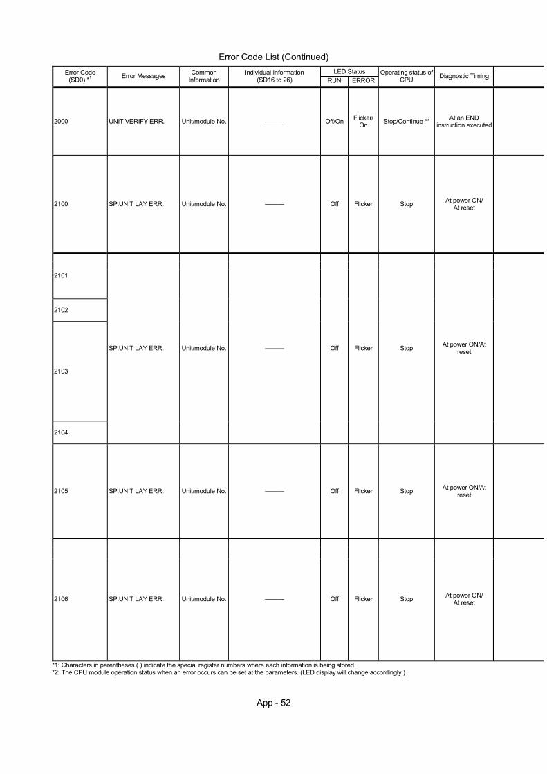
App - 52
Error Code List (Continued)
LED Status Error Code (SD0) *1 Error Messages Common
Information Individual Information
(SD16 to 26) RUN ERROROperating status of
CPU Diagnostic Timing
2000 UNIT VERIFY ERR. Unit/module No. ——— Off/On Flicker/On Stop/Continue *2 At an END
instruction executed
2100 SP.UNIT LAY ERR. Unit/module No. ——— Off Flicker Stop At power ON/ At reset
2101
2102
2103
2104
SP.UNIT LAY ERR. Unit/module No. ——— Off Flicker Stop At power ON/At reset
2105 SP.UNIT LAY ERR. Unit/module No. ——— Off Flicker Stop At power ON/At reset
2106 SP.UNIT LAY ERR. Unit/module No. ——— Off Flicker Stop At power ON/ At reset
*1: Characters in parentheses ( ) indicate the special register numbers where each information is being stored. *2: The CPU module operation status when an error occurs can be set at the parameters. (LED display will change accordingly.)
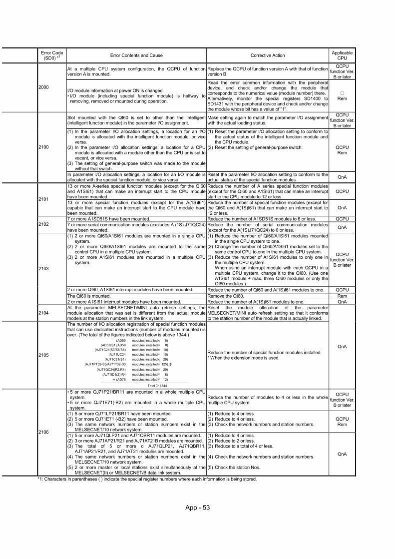
App - 53
Error Code (SD0) *1 Error Contents and Cause Corrective Action Applicable
CPU
At a multiple CPU system configuration, the QCPU of function version A is mounted.
Replace the QCPU of function version A with that of function version B.
QCPU function Ver.
B or later
2000 I/O module information at power ON is changed. • I/O module (including special function module) is halfway to
removing, removed or mounted during operation.
Read the error common information with the peripheral device, and check and/or change the module that corresponds to the numerical value (module number) there. Alternatively, monitor the special registers SD1400 to SD1431 with the peripheral device and check and/or change the module whose bit has a value of "1".
Rem
Slot mounted with the QI60 is set to other than the Intelligent (intelligent function module) in the parameter I/O assignment.
Make setting again to match the parameter I/O assignment with the actual loading status.
QCPU function Ver.
B or later (1) In the parameter I/O allocation settings, a location for an I/O
module is allocated with the intelligent function module, or vice versa.
(2) In the parameter I/O allocation settings, a location for a CPU module is allocated with a module other than the CPU or is set to vacant, or vice versa.
(3) The setting of general-purpose switch was made to the module without that switch.
(1) Reset the parameter I/O allocation setting to conform to the actual status of the intelligent function module and the CPU module.
(2) Reset the setting of general-purpose switch.
QCPU Rem
2100
In parameter I/O allocation settings, a location for an I/O module is allocated with the special function module, or vice versa.
Reset the parameter I/O allocation setting to conform to the actual status of the special function modules. QnA
13 or more A-series special function modules (except for the QI60 and A1SI61) that can make an interrupt start to the CPU module have been mounted.
Reduce the number of A series special function modules (except for the QI60 and A1SI61) that can make an interrupt start to the CPU module to 12 or less.
QCPU
2101 13 or more special function modules (except for the A(1S)I61) capable that can make an interrupt start to the CPU module have been mounted.
Reduce the number of special function modules (except for the QI60 and A(1S)I61) that can make an interrupt start to 12 or less.
QnA
7 or more A1SD51S have been mounted. Reduce the number of A1SD51S modules to 6 or less. QCPU
2102 7 or more serial communication modules (excludes A (1S) J71QC24) have been mounted.
Reduce the number of serial communication modules (except for the A(1S)J71QC24) to 6 or less. QnA
(1) 2 or more QI60/A1SI61 modules are mounted in a single CPU system.
(2) 2 or more QI60/A1SI61 modules are mounted to the same control CPU in a multiple CPU system.
(3) 2 or more A1SI61 modules are mounted in a multiple CPU system.
(1) Reduce the number of QI60/A1SI61 modules mounted in the single CPU system to one.
(2) Change the number of QI60/A1SI61 modules set to the same control CPU to one in the multiple CPU system.
(3) Reduce the number of A1SI61 modules to only one in the multiple CPU system. When using an interrupt module with each QCPU in a multiple CPU system, change it to the QI60. (Use one A1SI61 module + max. three QI60 modules or only the QI60 modules.)
QCPU function Ver.
B or later
2 or more QI60, A1SI61 interrupt modules have been mounted. Reduce the number of QI60 and A(1S)I61 modules to one. QCPU The QI60 is mounted. Remove the QI60. Rem
2103
2 or more A1SI61 interrupt modules have been mounted. Reduce the number of A(1S)I61 modules to one. QnA
2104 At the parameter MELSECNET/MINI auto refresh settings, the module allocation that was set is different from the actual module models at the station numbers in the link system.
Reset the module allocation of the parameter MELSECNET/MINI auto refresh setting so that it conforms to the station number of the module that is actually linked.
2105
The number of I/O allocation registration of special function modules that can use dedicated instructions (number of modules mounted) is over. (The total of the figures indicated below is above 1344.)
Total 1344
(AD59 modules installed 5) (AD57(S1)/AD58 modules installed 8)
(AJ71C24(S3/S6/S8) modules installed 10)(AJ71UC24 modules installed 10)
(AJ71C21(S1) modules installed 29)(AJ71PT32-S3/AJ71T32-S3 modules installed 125)
(AJ71QC24(R2,R4) modules installed 29) (AJ71ID1(2)-R4 modules installed 8)
(AD75 modules installed 12)
Reduce the number of special function modules installed. * When the extension mode is used.
QnA
• 5 or more QJ71P21/BR11 are mounted in a whole multiple CPU system.
• 5 or more QJ71E71(-B2) are mounted in a whole multiple CPU system.
Reduce the number of modules to 4 or less in the whole multiple CPU system.
QCPU function Ver.
B or later
(1) 5 or more QJ71LP21/BR11 have been mounted. (2) 5 or more QJ71E71 (-B2) have been mounted. (3) The same network numbers or station numbers exist in the
MELSECNET/10 network system.
(1) Reduce to 4 or less. (2) Reduce to 4 or less. (3) Check the network numbers and station numbers.
QCPU Rem
2106 (1) 5 or more AJ71QLP21 and AJ71QBR11 modules are mounted. (2) 3 or more AJ71AP21/R21 and AJ71AT21B modules are mounted. (3) The total of 5 or more d AJ71QLP21, AJ71QBR11,
AJ71AP21/R21, and AJ71AT21 modules are mounted. (4) The same network numbers or station numbers exist in the
MELSECNET/10 network system. (5) 2 or more master or local stations exist simultaneously at the
MELSECNET(II) or MELSECNET/B data link system.
(1) Reduce to 4 or less. (2) Reduce to 2 or less. (3) Reduce to a total of 4 or less. (4) Check the network numbers and station numbers. (5) Check the station Nos.
QnA
*1: Characters in parentheses ( ) indicate the special register numbers where each information is being stored.
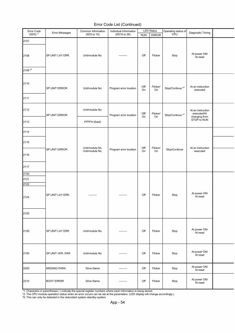
App - 54
Error Code List (Continued)
LED Status Error Code (SD0) *1 Error Messages Common Information
(SD5 to 15) Individual Information
(SD16 to 26) RUN ERROROperating status of
CPU Diagnostic Timing
2107
2108
2109 *6
SP.UNIT LAY ERR. Unit/module No. ——— Off Flicker Stop At power ON/ At reset
2110
2111
SP.UNIT ERROR Unit/module No. Program error location Off/ On
Flicker/ On Stop/Continue *2 At an instruction
executed
2112 Unit/module No.
2113
SP.UNIT ERROR
FFFFH (fixed)
Program error location Off/ On
Flicker/ On Stop/Continue *2
At an instruction executed/At
changing from STOP to RUN
2114
2115
2116
2117
SP.UNIT ERROR Unit/module No. Unit/module No. Program error location Off/
On Flicker/
On Stop/Continue At an instruction executed
2120
2121
2122
2124
2125
SP.UNIT LAY ERR. ——— ——— Off Flicker Stop At power ON/ At reset
2126 SP.UNIT LAY ERR. Unit/module No. ——— Off Flicker Stop At power ON/ At reset
2150 SP.UNIT VER. ERR. Unit/module No. ——— Off Flicker Stop At power ON/ At reset
2200 MISSING PARA. Drive Name ——— Off Flicker Stop At power ON/ At reset
2210 BOOT ERR0R Drive Name ——— Off Flicker Stop At power ON/ At reset
*1: Characters in parentheses ( ) indicate the special register numbers where each information is being stored. *2: The CPU module operation status when an error occurs can be set at the parameters. (LED display will change accordingly.) *6: This can only be detected in the redundant system standby system.
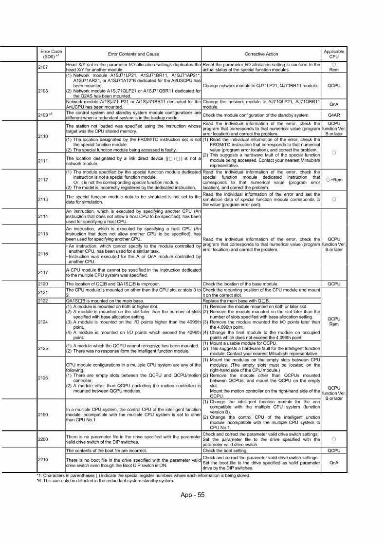
App - 55
Error Code (SD0) *1 Error Contents and Cause Corrective Action Applicable
CPU
2107 Head X/Y set in the parameter I/O allocation settings duplicates the head X/Y for another module.
Reset the parameter I/O allocation setting to conform to the actual status of the special function modules.
Rem
(1) Network module A1SJ71LP21, A1SJ71BR11, A1SJ71AP21*, A1SJ71AR21, or A1SJ71AT2*B dedicated for the A2USCPU has been mounted.
(2) Network module A1SJ71QLP21 or A1SJ71QBR11 dedicated for the Q2AS has been mounted.
Change network module to QJ71LP21, QJ71BR11 module. QCPU 2108
Network module A(1S)J71LP21 or A(1S)J71BR11 dedicated for the AnUCPU has been mounted.
Change the network module to AJ71QLP21, AJ71QBR11 module. QnA
2109 *6 The control system and standby system module configurations are different when a redundant system is in the backup mode. Check the module configuration of the standby system. Q4AR
The station not loaded was specified using the instruction whose target was the CPU shared memory.
Read the individual information of the error, check the program that corresponds to that numerical value (program error location) and correct the problem.
QCPU function Ver.
B or later
2110 (1) The location designated by the FROM/TO instruction set is not
the special function module. (2) The special function module being accessed is faulty.
2111 The location designated by a link direct device (j ) is not a network module.
(1) Read the individual information of the error, check the FROM/TO instruction that corresponds to that numerical value (program error location), and correct the problem.
(2) This suggests a hardware fault of the special function module being accessed. Contact your nearest Mitsubishi representative.
2112
(1) The module specified by the special function module dedicated instruction is not a special function module. Or, it is not the corresponding special function module.
(2) The model is incorrectly registered by the dedicated instruction.
Read the individual information of the error, check the special function module dedicated instruction that corresponds to that numerical value (program error location), and correct the problem.
+Rem
2113 The special function module data to be simulated is not set to the data for simulation.
Read the individual information of the error and set the simulation data of special function module corresponds to the value (program error part).
2114 An instruction, which is executed by specifying another CPU (An instruction that does not allow a host CPU to be specified), has been used for specifying a host CPU.
2115 An instruction, which is executed by specifying a host CPU (An instruction that does not allow another CPU to be specified), has been used for specifying another CPU.
2116
• An instruction, which cannot specify to the module controlled by another CPU, has been used for a similar task.
• Instruction was executed for the A or QnA module controlled by another CPU.
2117 A CPU module that cannot be specified in the instruction dedicated to the multiple CPU system was specified.
Read the individual information of the error, check the program that corresponds to that numerical value (program error location) and correct the problem.
QCPU function Ver.
B or later
2120 The location of Q B and QA1S B is improper. Check the location of the base module. QCPU
2121 The CPU module is mounted on other than the CPU slot or slots 0 to 2.
Check the mounting position of the CPU module and mount it on the correct slot.
2122 QA1S B is mounted on the main base. Replace the main base with Q B.
2124
(1) A module is mounted on 65th or higher slot. (2) A module is mounted on the slot later than the number of slots
specified with base allocation setting. (3) A module is mounted on the I/O points higher than the 4096th
point. (4) A module is mounted on I/O points which exceed the 4096th
point.
(1) Remove the module mounted on 65th or later slot. (2) Remove the module mounted on the slot later than the
number of slots specified with base allocation setting. (3) Remove the module mounted the I/O points later than
the 4,096th point. (4) Change the final module to the module on occupied
points which does not exceed the 4,096th point.
2125 (1) A module which the QCPU cannot recognize has been mounted.(2) There was no response form the intelligent function module.
(1) Mount a usable module for QCPU. (2) This suggests a hardware fault for the intelligent function
module. Contact your nearest Mitsubishi representative.
QCPU Rem
2126
CPU module configurations in a multiple CPU system are any of the following. (1) There are empty slots between the QCPU and QCPU/motion
controller. (2) A module other than QCPU (including the motion controller) is
mounted between QCPU modules.
(1) Mount the modules on the empty slots between CPU modules. (The empty slots must be located on the right-hand side of the CPU module.)
(2) Remove the module other than QCPUs mounted between QCPUs, and mount the QCPU on the empty slot. Mount the motion controller on the right-hand side of the QCPU.
2150 In a multiple CPU system, the control CPU of the intelligent function module incompatible with the multiple CPU system is set to other than CPU No.1.
(1) Change the intelligent function module for the one compatible with the multiple CPU system (function version B).
(2) Change the control CPU of the intelligent unction module incompatible with the multiple CPU system to CPU No.1.
QCPU function Ver.
B or later
2200 There is no parameter file in the drive specified with the parameter valid drive switch of the DIP switches.
Check and correct the parameter valid drive switch settings.Set the parameter file to the drive specified with the parameter valid drive switch.
The contents of the boot file are incorrect. Check the boot setting. QCPU
2210 There is no boot file in the drive specified with the parameter valid drive switch even though the Boot DIP switch is ON.
Check and correct the parameter valid drive switch settings.Set the boot file to the drive specified as valid parameter drive by the DIP switches.
QnA
*1: Characters in parentheses ( ) indicate the special register numbers where each information is being stored. *6: This can only be detected in the redundant system standby system.
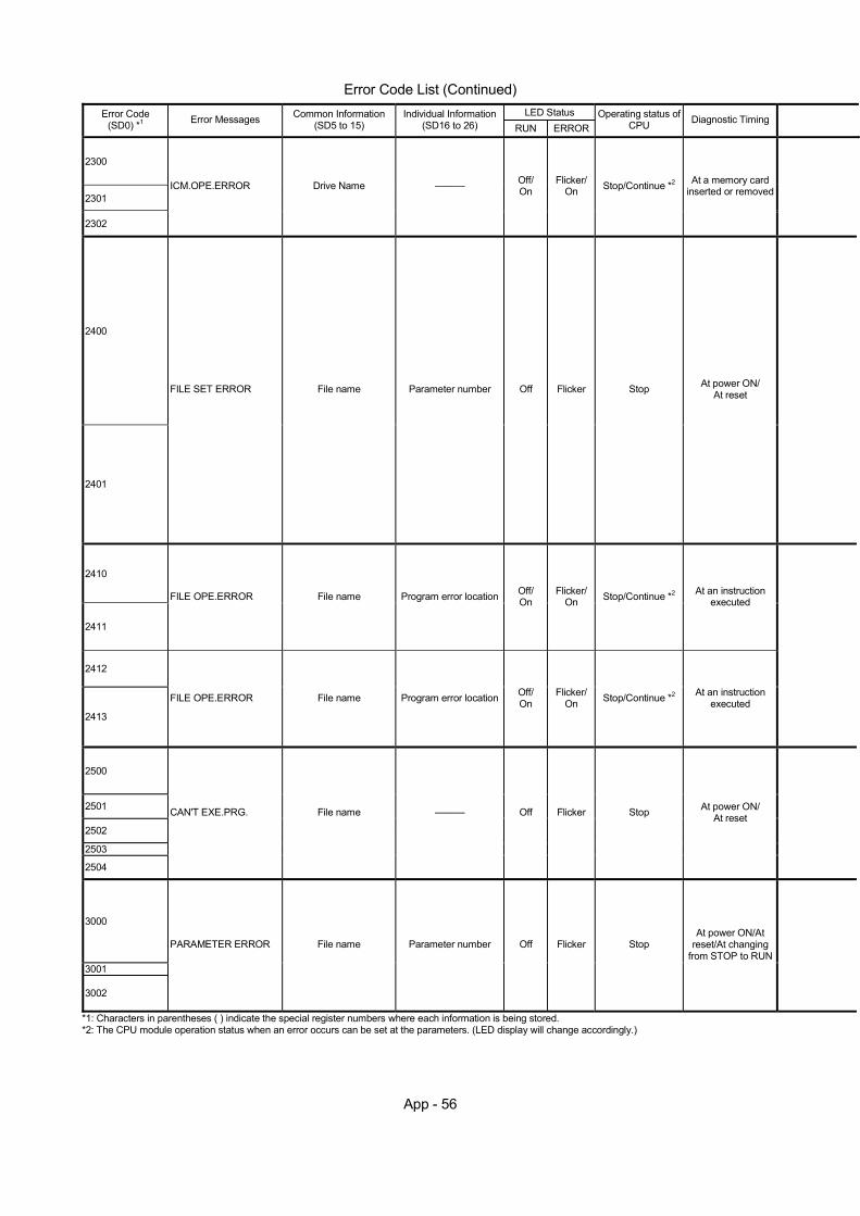
App - 56
Error Code List (Continued)
LED Status Error Code (SD0) *1 Error Messages Common Information
(SD5 to 15) Individual Information
(SD16 to 26) RUN ERROROperating status of
CPU Diagnostic Timing
2300
2301
2302
ICM.OPE.ERROR Drive Name ——— Off/ On
Flicker/ On Stop/Continue *2 At a memory card
inserted or removed
2400
2401
FILE SET ERROR File name Parameter number Off Flicker Stop At power ON/ At reset
2410
2411
FILE OPE.ERROR File name Program error location Off/ On
Flicker/ On Stop/Continue *2 At an instruction
executed
2412
2413
FILE OPE.ERROR File name Program error location Off/ On
Flicker/ On Stop/Continue *2 At an instruction
executed
2500
2501
2502
2503
2504
CAN'T EXE.PRG. File name ——— Off Flicker Stop At power ON/ At reset
3000
3001
3002
PARAMETER ERROR File name Parameter number Off Flicker Stop At power ON/At
reset/At changing from STOP to RUN
*1: Characters in parentheses ( ) indicate the special register numbers where each information is being stored. *2: The CPU module operation status when an error occurs can be set at the parameters. (LED display will change accordingly.)

App - 57
Error Code (SD0) *1 Error Contents and Cause Corrective Action Applicable
CPU
2300
(1) A memory card was removed without switching the memory card in/out switch OFF.
(2) The memory card in/out switch is turned ON although a memory card is not actually installed.
(1) Remove memory card after placing the memory card in/out switch OFF.
(2) Turn ON the card insert switch after installing a memory card.
2301 (1) The memory card has not been formatted. (2) Memory card format status is incorrect.
2302 A memory card that cannot be used with the Q/QnACPU module has been installed.
(1) Format the memory card. (2) Reformat the memory card.
Check the memory card.
Automatic write to standard ROM was performed on the QCPU module that is incompatible with automatic write to standard ROM. (Memory card where automatic write to standard ROM was selected in the boot file was installed and the parameter valid drive was set to the memory card.)
(1) Execute automatic write to standard ROM on the QCPU module which is compatible with automatic write to standard ROM.
(2) Using GX Developer, perform write of parameters and programs to standard ROM.
(3) Change the memory card to the one where automatic write to standard ROM has not been set, and perform the boot operation from the memory card.
QCPU function Ver.
B or later
The file designated in the parameters cannot be found.
Read the individual information of the error using peripheral device, check and correct the parameter drive name and file name correspond to the numerical values there (parameter number). Create a file designated in the parameters.
2400
The Ethernet parameter, which was added in QnACPU with the function version "B," has been set to QnACPU without the function version "B."
Change to QnACPU with the function version "B". Delete the Ethernet parameter. QnA
Program memory capacity was exceeded by performing boot operation or automatic write to standard ROM.
(1) Check and correct the parameters (boot setting). (2) Delete unnecessary files in the program memory. (3) Choose "Clear program memory" for boot in the
parameter so that boot is started after the program memory is cleared.
QCPU function Ver.
B or later
2401
The file designated in the parameter has not been created.
Read the individual information of the error using peripheral device, check and correct the parameter drive name and file name correspond to the numerical values there (parameter number). Check the space remaining in the memory card.
2410 The file designated in a sequence program cannot be found.
Read the individual information of the error using the peripheral device, check and correct the program that corresponds to that numerical value (program error location). Create a file designated in the parameters.
2411 File that cannot be specified in a sequence program (comment file, etc.)
Read the individual information of the error using the peripheral device, check and correct the program that corresponds to that numerical value (program error location).
2412 SFC program file that cannot be designated by the sequence program
Read the individual information of the error using the peripheral device, check and correct the program that corresponds to that numerical value (program error location).
2413 A data does not write to the file designated in a sequence program.
Read the individual information of the error using the peripheral device, check and correct the program that corresponds to that numerical value (program error location). Check whether the designated file has not been write protected.
2500 There is a program file that uses a device that is out of the device allocation range set in the parameter device setting.
Read the common information of the error using the peripheral device, check and correct the device allocation of the program file and the device allocation of parameter device setting that correspond to the numerical values (file name).
2501 There are multiple program files although "none" has been set at the parameter program settings.
Edit the PLC parameter program setting to "yes". Alternatively, delete unnecessary programs.
2502 The program file does not correspond to Q/QnACPU. Alternatively, the file contents are not those of a sequence program.
Check whether the program version is .QPG, and whether the file contents are those of a sequence program.
2503
2504
There are no program files at all. Two or more SFC normal programs and control programs have been executed.
Check program configuration. Check parameters and program configuration.
In a multiple CPU system, the intelligent function module under control of another CPU is specified in the interrupt pointer setting of the parameter.
(1) Specify the head I/O number of the intelligent function module under control of the host CPU.
(2) Delete the interrupt pointer setting of the parameter.
QCPU function Ver.
B or later 3000 The settings of timer time limit setting, the RUN-PAUSE contact, the
common pointer number, general data processing, number of empty slots, or system interrupt settings are set outside the range that can be used by the CPU module.
3001 Parameter contents are broken.
Rem
3002 When "Use the following file" is selected for the file register in the PLC file setting of the PLC parameter dialog box, the specified file does not exist in QCPU although the file register capacity has been set.
(1) Read the detailed information of the error using the peripheral device, check the parameter items corresponding to those numerical values (parameter numbers), and correct when necessary.
(2) If the error is still generated following the correction of the parameter settings, the possible cause is the memory error of the CPU module's built-in RAM or the memory card. Contact your nearest Mitsubishi representative.
*1: Characters in parentheses ( ) indicate the special register numbers where each information is being stored.
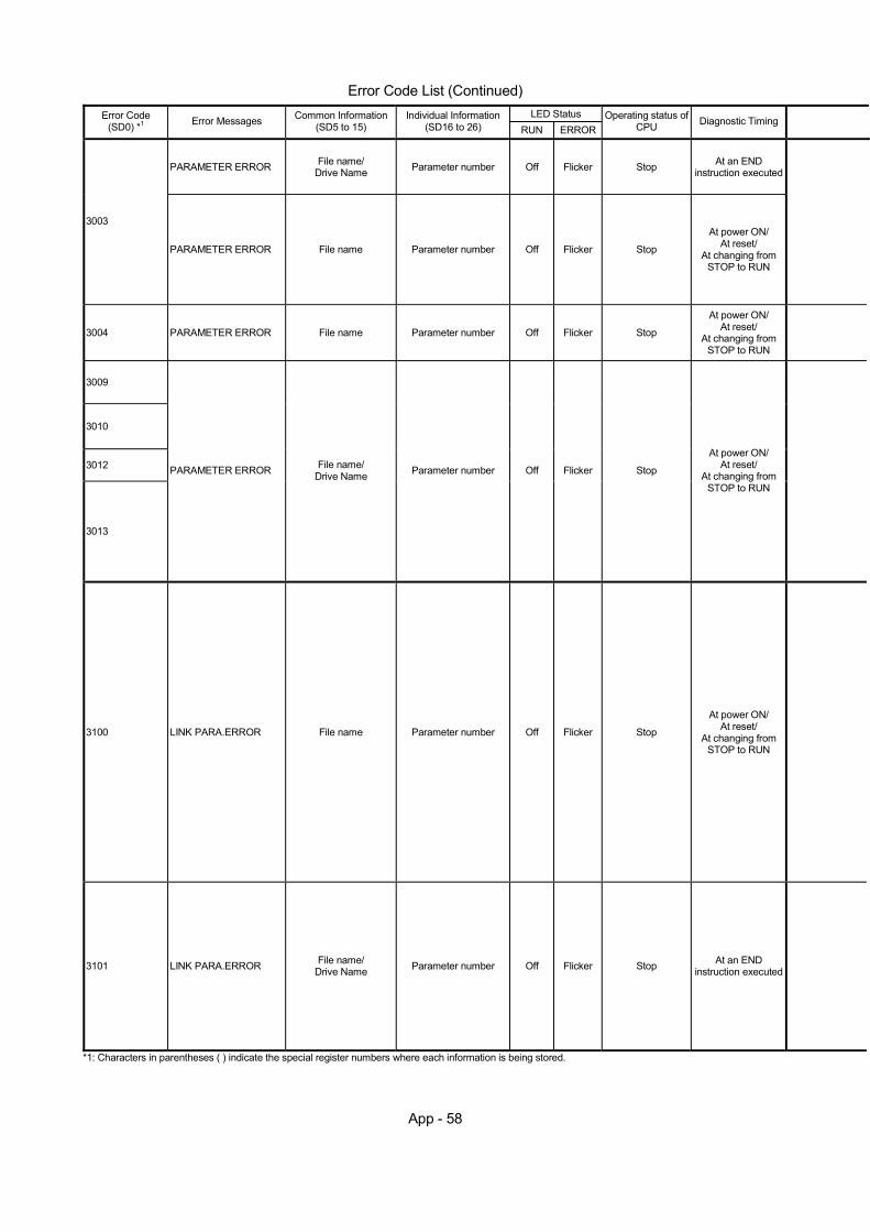
App - 58
Error Code List (Continued)
LED Status Error Code (SD0) *1 Error Messages Common Information
(SD5 to 15) Individual Information
(SD16 to 26) RUN ERROROperating status of
CPU Diagnostic Timing
PARAMETER ERROR File name/ Drive Name Parameter number Off Flicker Stop At an END
instruction executed
3003
PARAMETER ERROR File name Parameter number Off Flicker Stop
At power ON/ At reset/
At changing from STOP to RUN
3004 PARAMETER ERROR File name Parameter number Off Flicker Stop
At power ON/ At reset/
At changing from STOP to RUN
3009
3010
3012
3013
PARAMETER ERROR File name/ Drive Name Parameter number Off Flicker Stop
At power ON/ At reset/
At changing from STOP to RUN
3100 LINK PARA.ERROR File name Parameter number Off Flicker Stop
At power ON/ At reset/
At changing from STOP to RUN
3101 LINK PARA.ERROR File name/ Drive Name Parameter number Off Flicker Stop At an END
instruction executed
*1: Characters in parentheses ( ) indicate the special register numbers where each information is being stored.
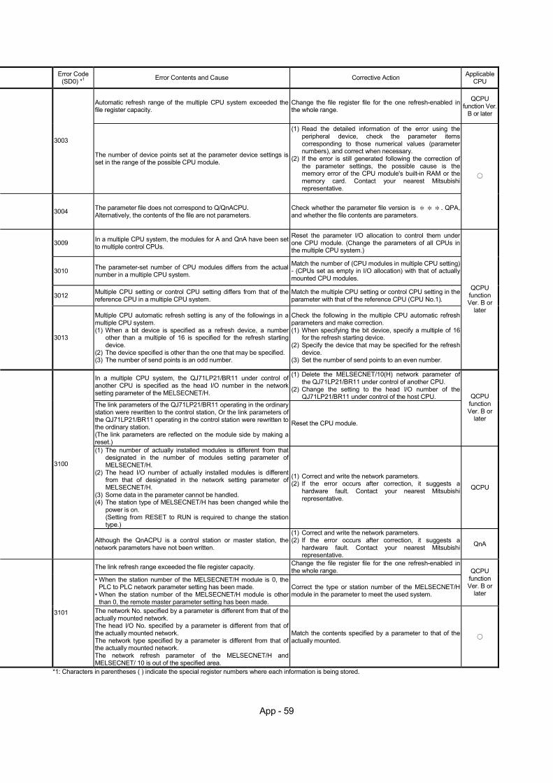
App - 59
Error Code (SD0) *1 Error Contents and Cause Corrective Action Applicable
CPU
Automatic refresh range of the multiple CPU system exceeded the file register capacity.
Change the file register file for the one refresh-enabled in the whole range.
QCPU function Ver.
B or later
3003
The number of device points set at the parameter device settings is set in the range of the possible CPU module.
(1) Read the detailed information of the error using the peripheral device, check the parameter items corresponding to those numerical values (parameter numbers), and correct when necessary.
(2) If the error is still generated following the correction of the parameter settings, the possible cause is the memory error of the CPU module's built-in RAM or the memory card. Contact your nearest Mitsubishi representative.
3004 The parameter file does not correspond to Q/QnACPU. Alternatively, the contents of the file are not parameters.
Check whether the parameter file version is . QPA, and whether the file contents are parameters.
3009 In a multiple CPU system, the modules for A and QnA have been set to multiple control CPUs.
Reset the parameter I/O allocation to control them under one CPU module. (Change the parameters of all CPUs in the multiple CPU system.)
3010 The parameter-set number of CPU modules differs from the actual number in a multiple CPU system.
Match the number of (CPU modules in multiple CPU setting) - (CPUs set as empty in I/O allocation) with that of actually mounted CPU modules.
3012 Multiple CPU setting or control CPU setting differs from that of the reference CPU in a multiple CPU system.
Match the multiple CPU setting or control CPU setting in the parameter with that of the reference CPU (CPU No.1).
3013
Multiple CPU automatic refresh setting is any of the followings in a multiple CPU system. (1) When a bit device is specified as a refresh device, a number
other than a multiple of 16 is specified for the refresh starting device.
(2) The device specified is other than the one that may be specified. (3) The number of send points is an odd number.
Check the following in the multiple CPU automatic refresh parameters and make correction. (1) When specifying the bit device, specify a multiple of 16
for the refresh starting device. (2) Specify the device that may be specified for the refresh
device. (3) Set the number of send points to an even number.
QCPU function Ver. B or
later
In a multiple CPU system, the QJ71LP21/BR11 under control of another CPU is specified as the head I/O number in the network setting parameter of the MELSECNET/H.
(1) Delete the MELSECNET/10(H) network parameter of the QJ71LP21/BR11 under control of another CPU.
(2) Change the setting to the head I/O number of the QJ71LP21/BR11 under control of the host CPU.
The link parameters of the QJ71LP21/BR11 operating in the ordinary station were rewritten to the control station, Or the link parameters of the QJ71LP21/BR11 operating in the control station were rewritten to the ordinary station. (The link parameters are reflected on the module side by making a reset.)
Reset the CPU module.
QCPU function Ver. B or
later
(1) The number of actually installed modules is different from that designated in the number of modules setting parameter of MELSECNET/H.
(2) The head I/O number of actually installed modules is different from that of designated in the network setting parameter of MELSECNET/H.
(3) Some data in the parameter cannot be handled. (4) The station type of MELSECNET/H has been changed while the
power is on. (Setting from RESET to RUN is required to change the station type.)
(1) Correct and write the network parameters. (2) If the error occurs after correction, it suggests a
hardware fault. Contact your nearest Mitsubishi representative.
QCPU
3100
Although the QnACPU is a control station or master station, the network parameters have not been written.
(1) Correct and write the network parameters. (2) If the error occurs after correction, it suggests a
hardware fault. Contact your nearest Mitsubishi representative.
QnA
The link refresh range exceeded the file register capacity. Change the file register file for the one refresh-enabled in the whole range.
• When the station number of the MELSECNET/H module is 0, the PLC to PLC network parameter setting has been made.
• When the station number of the MELSECNET/H module is other than 0, the remote master parameter setting has been made.
Correct the type or station number of the MELSECNET/H module in the parameter to meet the used system.
QCPU function Ver. B or
later
3101 The network No. specified by a parameter is different from that of the actually mounted network. The head I/O No. specified by a parameter is different from that of the actually mounted network. The network type specified by a parameter is different from that of the actually mounted network. The network refresh parameter of the MELSECNET/H and MELSECNET/ 10 is out of the specified area.
Match the contents specified by a parameter to that of the actually mounted.
*1: Characters in parentheses ( ) indicate the special register numbers where each information is being stored.
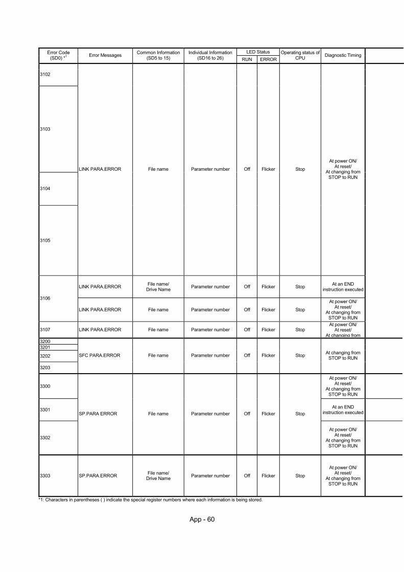
App - 60
LED Status Error Code (SD0) *1 Error Messages Common Information
(SD5 to 15) Individual Information
(SD16 to 26) RUN ERROROperating status of
CPU Diagnostic Timing
3102
3103
3104
3105
LINK PARA.ERROR File name Parameter number Off Flicker Stop
At power ON/ At reset/
At changing from STOP to RUN
LINK PARA.ERROR File name/ Drive Name Parameter number Off Flicker Stop At an END
instruction executed
3106
LINK PARA.ERROR File name Parameter number Off Flicker Stop
At power ON/ At reset/
At changing from STOP to RUN
3107 LINK PARA.ERROR File name Parameter number Off Flicker Stop At power ON/
At reset/ At changing from
3200 3201
3202
3203
SFC PARA.ERROR File name Parameter number Off Flicker Stop At changing from STOP to RUN
3300
At power ON/ At reset/
At changing from STOP to RUN
3301 At an END instruction executed
3302
SP.PARA ERROR File name Parameter number Off Flicker Stop
At power ON/ At reset/
At changing from STOP to RUN
3303 SP.PARA.ERROR File name/ Drive Name Parameter number Off Flicker Stop
At power ON/ At reset/
At changing from STOP to RUN
*1: Characters in parentheses ( ) indicate the special register numbers where each information is being stored.
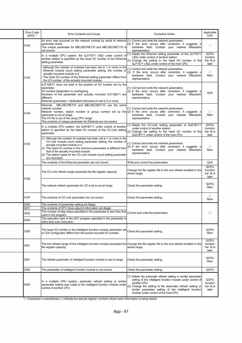
App - 61
Error Code (SD0) *1 Error Contents and Cause Corrective Action Applicable
CPU
3102
An error was occurred on the network module by result of network parameter check. The unique parameter for MELSECNET/H and MELSECNET/10 is not correct.
(1) Correct and write the network parameters. (2) If the error occurs after correction, it suggests a
hardware fault. Contact your nearest Mitsubishi representative.
In a multiple CPU system, the QJ71E71 (-B2) under control of another station is specified as the head I/O number of the Ethernet setting parameter.
(1) Delete the Ethernet setting parameter of the QJ71E71 (-B2) under control of another station.
(2) Change the setting to the head I/O number of the QJ71E71 (-B2) under control of the host CPU.
QCPU function Ver. B or
later • Although the number of modules has been set to 1 or more in the
Ethernet module count setting parameter setting, the number of actually mounted module is 0.
• The head I/O number of the Ethernet setting parameter differs from the I/O number. of the actually mounted module.
(1) Correct and write the network parameters. (2) If the error occurs after correction, it suggests a
hardware fault. Contact your nearest Mitsubishi representative.
Rem
3103
AJ71QE71 does not exist in the position of I/O number set by the parameter. I/O number designation is overlapping. Numbers of the parameter and actually mounted AJ71QE71 are different. Ethernet (parameter + dedicated instruction) is set to 5 or more.
(1) Correct and write the network parameters. (2) If the error occurs after correction, it suggests a
hardware fault. Contact your nearest Mitsubishi representative.
QnA
3104
Ethernet , MELSECNET/H and MELSECNET/10 use the same network number. Network number, station number or group number set by the parameter is out of range. The I/O No.is out of the using CPU range. The contents of unique parameter for Ethernet are not correct.
(1) Correct and write the network parameters. (2) If the error occurs after correction, it suggests a
hardware fault. Contact your nearest Mitsubishi representative.
Rem
In a multiple CPU system, the QJ61BT11 under control of another station is specified as the head I/O number of the CC-Link setting parameter.
(1) Delete the CC-Link setting parameter of QJ61BT11 under control of another station.
(2) Change the setting to the head I/O number of the QJ61BT11 under control of the host CPU.
QCPU function Ver. B or
later (1) Although the number of modules has been set to 1 or more in the
CC-Link module count setting parameter setting, the number of actually mounted module is 0.
(2) The head I/O number in the common parameters is different from that of the actually mounted module.
(3) The station types for the CC-Link module count setting parameter are mismatch.
(1) Correct and write the network parameters. (2) If the error occurs after correction, it suggests a
hardware fault. Contact your nearest Mitsubishi representative.
Rem
3105
The contents of the Ethernet parameter are not correct. Write and correct the parameters. QnA
The CC-Link refresh range exceeded the file register capacity. Change the file register file to the one refresh-enabled in the whole range.
QCPU function Ver. B or
later
3106
The network refresh parameter for CC-Link is out of range. Check the parameter setting. QCPU Rem
3107 The contents of CC-Link parameter are not correct. Check the parameter setting. Rem
3200 The contents of parameter setting are illegal. 3201 The contents of SFC block adjunct information are illegal.
3202 The number of step relays specified in the parameter is less than that used in the program.
3203 The execution type of the SFC program specified in the parameter is other than scan execution.
Correct and write the parameters.
3300 The head I/O number in the intelligent function module parameter set on GX Configurator differs from the actual mounted I/O number.
Check the parameter setting.
QCPU Rem
3301 The link refresh range of the intelligent function module exceeded the file register capacity.
Change the file register file to the one refresh-enabled in the whole range.
QCPU function Ver. B or
later
3301 The refresh parameter of intelligent function module is out of range. Check the parameter setting.
QCPU Rem
3302 The parameter of intelligent function module is not correct. Check the parameter setting. QCPU
3303 In a multiple CPU system, automatic refresh setting or similar parameter setting was made to the intelligent function module under control of another CPU.
(1) Delete the automatic refresh setting or similar parameter setting of the intelligent function module under control of another CPU.
(2) Change the setting to the automatic refresh setting or similar parameter setting of the intelligent function module under control of the host CPU.
QCPU function Ver. B or
later
*1: Characters in parentheses ( ) indicate the special register numbers where each information is being stored.
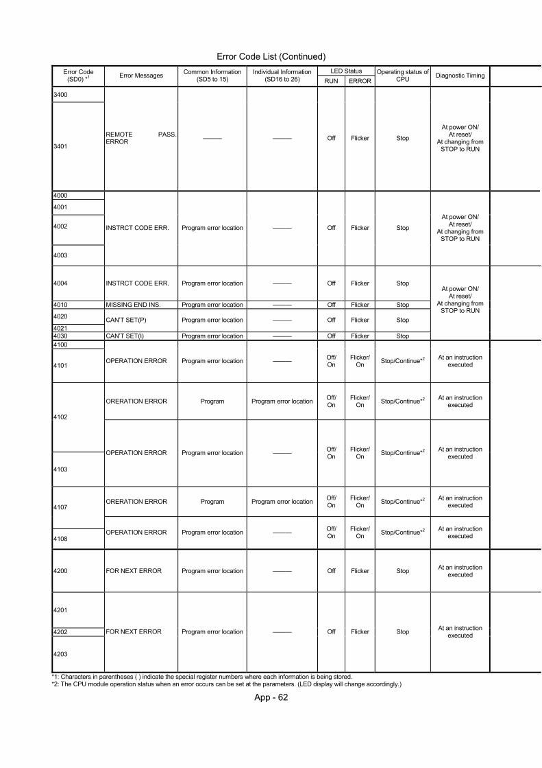
App - 62
Error Code List (Continued)
LED Status Error Code (SD0) *1 Error Messages Common Information
(SD5 to 15) Individual Information
(SD16 to 26) RUN ERROROperating status of
CPU Diagnostic Timing
3400
3401
REMOTE PASS. ERROR ——— ——— Off Flicker Stop
At power ON/ At reset/
At changing from STOP to RUN
4000
4001
4002
4003
INSTRCT CODE ERR. Program error location ——— Off Flicker Stop
At power ON/ At reset/
At changing from STOP to RUN
4004 INSTRCT CODE ERR. Program error location ——— Off Flicker Stop
4010 MISSING END INS. Program error location ——— Off Flicker Stop
4020
4021 CAN’T SET(P) Program error location ——— Off Flicker Stop
4030 CAN’T SET(I) Program error location ——— Off Flicker Stop
At power ON/ At reset/
At changing from STOP to RUN
4100
4101 OPERATION ERROR Program error location ——— Off/
On Flicker/
On Stop/Continue*2 At an instruction executed
ORERATION ERROR Program Program error location Off/ On
Flicker/ On Stop/Continue*2 At an instruction
executed
4102
4103
OPERATION ERROR Program error location ——— Off/ On
Flicker/ On Stop/Continue*2 At an instruction
executed
ORERATION ERROR Program Program error location Off/ On
Flicker/ On Stop/Continue*2 At an instruction
executed
4107
4108 OPERATION ERROR Program error location ——— Off/
On Flicker/
On Stop/Continue*2 At an instruction executed
4200 FOR NEXT ERROR Program error location ——— Off Flicker Stop At an instruction executed
4201
4202
4203
FOR NEXT ERROR Program error location ——— Off Flicker Stop At an instruction executed
*1: Characters in parentheses ( ) indicate the special register numbers where each information is being stored. *2: The CPU module operation status when an error occurs can be set at the parameters. (LED display will change accordingly.)
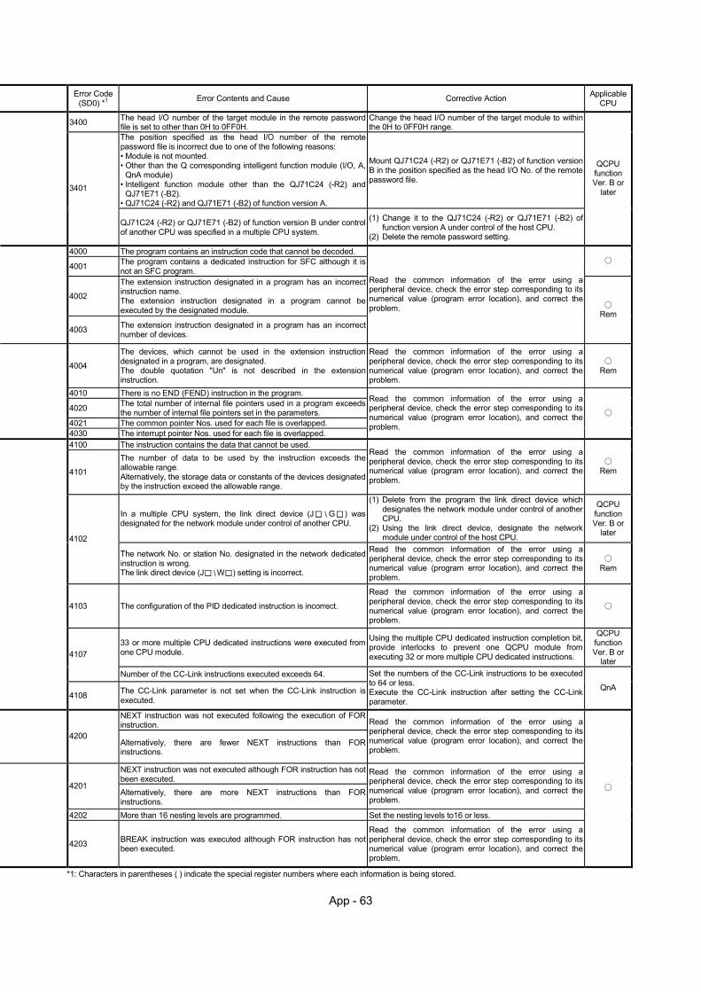
App - 63
Error Code (SD0) *1 Error Contents and Cause Corrective Action Applicable
CPU
3400 The head I/O number of the target module in the remote password file is set to other than 0H to 0FF0H.
Change the head I/O number of the target module to within the 0H to 0FF0H range.
The position specified as the head I/O number of the remote password file is incorrect due to one of the following reasons: • Module is not mounted. • Other than the Q corresponding intelligent function module (I/O, A,
QnA module) • Intelligent function module other than the QJ71C24 (-R2) and
QJ71E71 (-B2). • QJ71C24 (-R2) and QJ71E71 (-B2) of function version A.
Mount QJ71C24 (-R2) or QJ71E71 (-B2) of function version B in the position specified as the head I/O No. of the remote password file.
3401
QJ71C24 (-R2) or QJ71E71 (-B2) of function version B under control of another CPU was specified in a multiple CPU system.
(1) Change it to the QJ71C24 (-R2) or QJ71E71 (-B2) of function version A under control of the host CPU.
(2) Delete the remote password setting.
QCPU function Ver. B or
later
4000 The program contains an instruction code that cannot be decoded.
4001 The program contains a dedicated instruction for SFC although it is not an SFC program.
4002
The extension instruction designated in a program has an incorrect instruction name. The extension instruction designated in a program cannot be executed by the designated module.
4003 The extension instruction designated in a program has an incorrect number of devices.
Read the common information of the error using a peripheral device, check the error step corresponding to its numerical value (program error location), and correct the problem.
Rem
4004
The devices, which cannot be used in the extension instruction designated in a program, are designated. The double quotation "Un" is not described in the extension instruction.
Read the common information of the error using a peripheral device, check the error step corresponding to its numerical value (program error location), and correct the problem.
Rem
4010 There is no END (FEND) instruction in the program.
4020 The total number of internal file pointers used in a program exceeds the number of internal file pointers set in the parameters.
4021 The common pointer Nos. used for each file is overlapped.
4030 The interrupt pointer Nos. used for each file is overlapped.
Read the common information of the error using a peripheral device, check the error step corresponding to its numerical value (program error location), and correct the problem.
4100 The instruction contains the data that cannot be used.
4101
The number of data to be used by the instruction exceeds the allowable range. Alternatively, the storage data or constants of the devices designated by the instruction exceed the allowable range.
Read the common information of the error using a peripheral device, check the error step corresponding to its numerical value (program error location), and correct the problem.
Rem
In a multiple CPU system, the link direct device (J G ) was designated for the network module under control of another CPU.
(1) Delete from the program the link direct device which designates the network module under control of another CPU.
(2) Using the link direct device, designate the network module under control of the host CPU.
QCPU function Ver. B or
later 4102
The network No. or station No. designated in the network dedicated instruction is wrong. The link direct device (J W ) setting is incorrect.
Read the common information of the error using a peripheral device, check the error step corresponding to its numerical value (program error location), and correct the problem.
Rem
4103 The configuration of the PID dedicated instruction is incorrect.
Read the common information of the error using a peripheral device, check the error step corresponding to its numerical value (program error location), and correct the problem.
33 or more multiple CPU dedicated instructions were executed from one CPU module.
Using the multiple CPU dedicated instruction completion bit, provide interlocks to prevent one QCPU module from executing 32 or more multiple CPU dedicated instructions.
QCPU function Ver. B or
later 4107
Number of the CC-Link instructions executed exceeds 64.
4108 The CC-Link parameter is not set when the CC-Link instruction is executed.
Set the numbers of the CC-Link instructions to be executed to 64 or less. Execute the CC-Link instruction after setting the CC-Link parameter.
QnA
NEXT instruction was not executed following the execution of FOR instruction.
4200 Alternatively, there are fewer NEXT instructions than FOR instructions.
Read the common information of the error using a peripheral device, check the error step corresponding to its numerical value (program error location), and correct the problem.
NEXT instruction was not executed although FOR instruction has not been executed.
4201 Alternatively, there are more NEXT instructions than FOR instructions.
Read the common information of the error using a peripheral device, check the error step corresponding to its numerical value (program error location), and correct the problem.
4202 More than 16 nesting levels are programmed. Set the nesting levels to16 or less.
4203 BREAK instruction was executed although FOR instruction has not been executed.
Read the common information of the error using a peripheral device, check the error step corresponding to its numerical value (program error location), and correct the problem.
*1: Characters in parentheses ( ) indicate the special register numbers where each information is being stored.
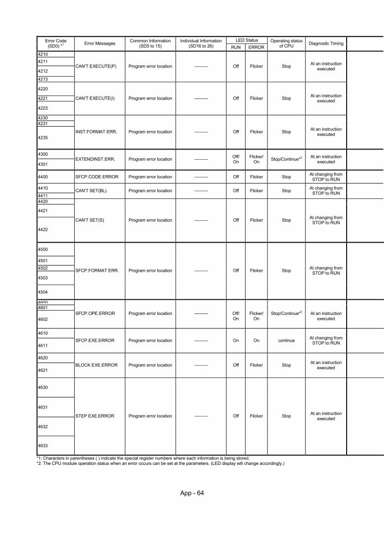
App - 64
LED Status Error Code
(SD0) *1 Error Messages Common Information (SD5 to 15)
Individual Information (SD16 to 26) RUN ERROR
Operating status of CPU Diagnostic Timing
4210 4211
4212
4213
CAN’T EXECUTE(P) Program error location ——— Off Flicker Stop At an instruction executed
4220
4221
4223
CAN’T EXECUTE(I) Program error location ——— Off Flicker Stop At an instruction executed
4230 4231
4235 INST.FORMAT ERR. Program error location ——— Off Flicker Stop At an instruction
executed
4300
4301 EXTENDINST.ERR. Program error location ——— Off/
On Flicker/
On Stop/Continue*2 At an instruction executed
4400 SFCP.CODE ERROR Program error location ——— Off Flicker Stop At changing from STOP to RUN
4410
4411 CAN’T SET(BL) Program error location ——— Off Flicker Stop At changing from
STOP to RUN
4420
4421
4422
CAN’T SET(S) Program error location ——— Off Flicker Stop At changing from STOP to RUN
4500
4501 4502
4503
4504
SFCP.FORMAT ERR. Program error location ——— Off Flicker Stop At changing from STOP to RUN
46004601
4602 SFCP.OPE.ERROR Program error location ——— Off/
On Flicker/
On Stop/Continue*2 At an instruction
executed
4610
4611 SFCP.EXE.ERROR Program error location ——— On On continue At changing from
STOP to RUN
4620
4621 BLOCK EXE.ERROR Program error location ——— Off Flicker Stop At an instruction
executed
4630
4631
4632
4633
STEP EXE.ERROR Program error location ——— Off Flicker Stop At an instruction executed
*1: Characters in parentheses ( ) indicate the special register numbers where each information is being stored. *2: The CPU module operation status when an error occurs can be set at the parameters. (LED display will change accordingly.)
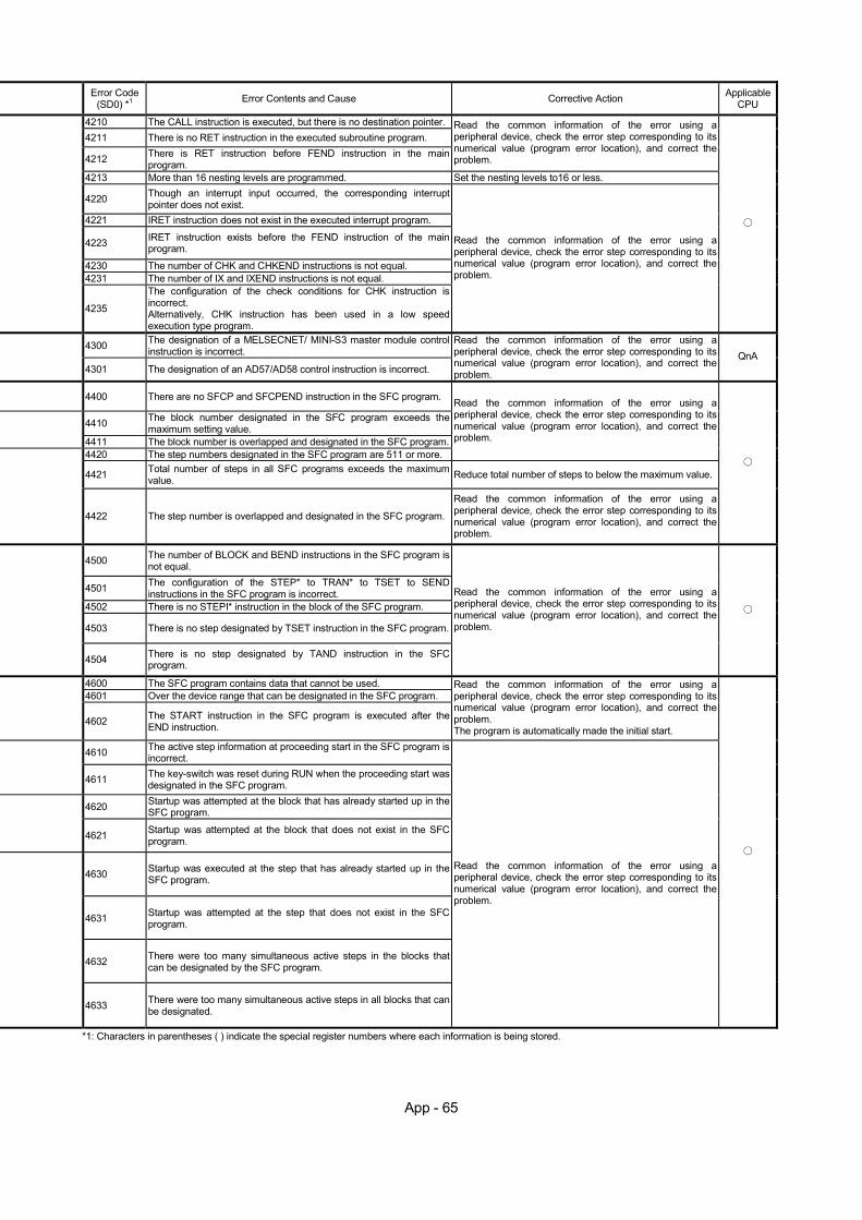
App - 65
Error Code (SD0) *1 Error Contents and Cause Corrective Action Applicable
CPU
4210 The CALL instruction is executed, but there is no destination pointer. 4211 There is no RET instruction in the executed subroutine program.
4212 There is RET instruction before FEND instruction in the main program.
Read the common information of the error using a peripheral device, check the error step corresponding to its numerical value (program error location), and correct the problem.
4213 More than 16 nesting levels are programmed. Set the nesting levels to16 or less.
4220 Though an interrupt input occurred, the corresponding interrupt pointer does not exist.
4221 IRET instruction does not exist in the executed interrupt program.
4223 IRET instruction exists before the FEND instruction of the main program.
4230 The number of CHK and CHKEND instructions is not equal. 4231 The number of IX and IXEND instructions is not equal.
4235
The configuration of the check conditions for CHK instruction is incorrect. Alternatively, CHK instruction has been used in a low speed execution type program.
Read the common information of the error using a peripheral device, check the error step corresponding to its numerical value (program error location), and correct the problem.
4300 The designation of a MELSECNET/ MINI-S3 master module control instruction is incorrect.
4301 The designation of an AD57/AD58 control instruction is incorrect.
Read the common information of the error using a peripheral device, check the error step corresponding to its numerical value (program error location), and correct the problem.
QnA
4400 There are no SFCP and SFCPEND instruction in the SFC program.
4410 The block number designated in the SFC program exceeds the maximum setting value.
4411 The block number is overlapped and designated in the SFC program.4420 The step numbers designated in the SFC program are 511 or more.
Read the common information of the error using a peripheral device, check the error step corresponding to its numerical value (program error location), and correct the problem.
4421 Total number of steps in all SFC programs exceeds the maximum value. Reduce total number of steps to below the maximum value.
4422 The step number is overlapped and designated in the SFC program.
Read the common information of the error using a peripheral device, check the error step corresponding to its numerical value (program error location), and correct the problem.
4500 The number of BLOCK and BEND instructions in the SFC program is not equal.
4501 The configuration of the STEP* to TRAN* to TSET to SEND instructions in the SFC program is incorrect.
4502 There is no STEPI* instruction in the block of the SFC program.
4503 There is no step designated by TSET instruction in the SFC program.
4504 There is no step designated by TAND instruction in the SFC program.
Read the common information of the error using a peripheral device, check the error step corresponding to its numerical value (program error location), and correct the problem.
4600 The SFC program contains data that cannot be used. 4601 Over the device range that can be designated in the SFC program.
4602 The START instruction in the SFC program is executed after the
END instruction.
Read the common information of the error using a peripheral device, check the error step corresponding to its numerical value (program error location), and correct the problem. The program is automatically made the initial start.
4610 The active step information at proceeding start in the SFC program is incorrect.
4611 The key-switch was reset during RUN when the proceeding start was
designated in the SFC program.
4620 Startup was attempted at the block that has already started up in the SFC program.
4621 Startup was attempted at the block that does not exist in the SFC
program.
4630 Startup was executed at the step that has already started up in the SFC program.
4631 Startup was attempted at the step that does not exist in the SFC program.
4632 There were too many simultaneous active steps in the blocks that can be designated by the SFC program.
4633 There were too many simultaneous active steps in all blocks that can be designated.
Read the common information of the error using a peripheral device, check the error step corresponding to its numerical value (program error location), and correct the problem.
*1: Characters in parentheses ( ) indicate the special register numbers where each information is being stored.
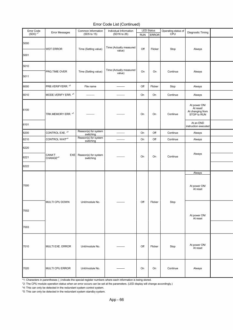
App - 66
Error Code List (Continued)
LED Status Error Code (SD0) *1 Error Messages Common Information
(SD5 to 15) Individual Information
(SD16 to 26) RUN ERROROperating status of
CPU Diagnostic Timing
5000
5001
WDT ERROR Time (Setting value) Time (Actually measured value) Off Flicker Stop Always
5010
5011
PRG.TIME OVER Time (Setting value) Time (Actually measured value) On On Continue Always
6000 PRB.VERIFYERR. *5 File name ——— Off Flicker Stop Always
6010 MODE.VERIFY ERR. *5 ——— ——— On On Continue Always
6100
At power ON/ At reset/
At changing from STOP to RUN
6101
TRK.MEMORY ERR. *3 ——— ——— On On Continue
At an END instruction executed
6200 CONTROL EXE. *4 Reason(s) for system switching ——— On Off Continue Always
6210 CONTROL WAIT*4 Reason(s) for system switching ——— On Off Continue Always
6220
6221
6222
CANA’T EXE CHANGE*4
Reason(s) for system switching ——— On On Continue
Always
Always
7000 At power ON/ At reset
7002
7003
MULTI CPU DOWN Unit/module No. ——— Off Flicker Stop
At power ON/ At reset
7010 MULTI EXE. ERROR Unit/module No. ——— Off Flicker Stop At power ON/ At reset
7020 MULTI CPU ERROR Unit/module No. ——— On On Continue Always
*1: Characters in parentheses ( ) indicate the special register numbers where each information is being stored. *2: The CPU module operation status when an error occurs can be set at the parameters. (LED display will change accordingly.) *4: This can only be detected in the redundant system control system. *5: This can only be detected in the redundant system standby system.
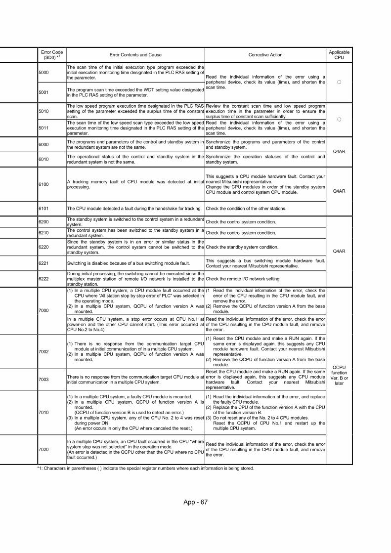
App - 67
Error Code (SD0) *1 Error Contents and Cause Corrective Action Applicable
CPU
5000 The scan time of the initial execution type program exceeded the initial execution monitoring time designated in the PLC RAS setting of the parameter.
5001 The program scan time exceeded the WDT setting value designated in the PLC RAS setting of the parameter.
Read the individual information of the error using a peripheral device, check its value (time), and shorten the scan time.
5010 The low speed program execution time designated in the PLC RAS setting of the parameter exceeded the surplus time of the constant scan.
Review the constant scan time and low speed program execution time in the parameter in order to ensure the surplus time of constant scan sufficiently.
5011 The scan time of the low speed scan type exceeded the low speed execution monitoring time designated in the PLC RAS setting of the parameter.
Read the individual information of the error using a peripheral device, check its value (time), and shorten the scan time.
6000 The programs and parameters of the control and standby system in the redundant system are not the same.
Synchronize the programs and parameters of the control and standby system.
6010 The operational status of the control and standby system in the redundant system is not the same.
Synchronize the operation statuses of the control and standby system.
Q4AR
6100 A tracking memory fault of CPU module was detected at initial processing.
This suggests a CPU module hardware fault. Contact your nearest Mitsubishi representative. Change the CPU modules in order of the standby system CPU module and control system CPU module.
6101 The CPU module detected a fault during the handshake for tracking. Check the condition of the other stations.
Q4AR
6200 The standby system is switched to the control system in a redundant system. Check the control system condition.
6210 The control system has been switched to the standby system in a redundant system. Check the control system condition.
6220 Since the standby system is in an error or similar status in the redundant system, the control system cannot be switched to the standby system.
Check the standby system condition.
6221 Switching is disabled because of a bus switching module fault. This suggests a bus switching module hardware fault. Contact your nearest Mitsubishi representative.
6222 During initial processing, the switching cannot be executed since the multiplex master station of remote I/O network is installed to the standby station.
Check the remote I/O network setting.
Q4AR
(1) In a multiple CPU system, a CPU module fault occurred at the CPU where "All station stop by stop error of PLC" was selected in the operating mode.
(2) In a multiple CPU system, QCPU of function version A was mounted.
(1 Read the individual information of the error, check the error of the CPU resulting in the CPU module fault, and remove the error.
(2) Remove the QCPU of function version A from the base module. 7000
In a multiple CPU system, a stop error occurs at CPU No.1 at power-on and the other CPU cannot start. (This error occurred at CPU No.2 to No.4)
Read the individual information of the error, check the error of the CPU resulting in the CPU module fault, and remove the error.
7002
(1) There is no response from the communication target CPU module at initial communication of in a multiple CPU system.
(2) In a multiple CPU system, QCPU of function version A was mounted.
(1) Reset the CPU module and make a RUN again. If the same error is displayed again, this suggests any CPU module hardware fault. Contact your nearest Mitsubishi representative.
(2) Remove the QCPU of function version A from the base module.
7003 There is no response from the communication target CPU module at initial communication in a multiple CPU system.
Reset the CPU module and make a RUN again. If the same error is displayed again, this suggests any CPU module hardware fault. Contact your nearest Mitsubishi representative.
7010
(1) In a multiple CPU system, a faulty CPU module is mounted. (2) In a multiple CPU system, QCPU of function version A is
mounted. (QCPU of function version B is used to detect an error.)
(3) In a multiple CPU system, any of the CPU No. 2 to 4 was reset during power ON. (An error occurs in only the CPU where canceled the reset.)
(1) Read the individual information of the error, and replace the faulty CPU module.
(2) Replace the CPU of the function version A with the CPU of the function version B.
(3) Do not reset any of the No. 2 to 4 CPU modules. Reset the QCPU of CPU No.1 and restart up the multiple CPU system.
7020
In a multiple CPU system, an CPU fault occurred in the CPU "where system stop was not selected" in the operation mode. (An error is detected in the QCPU other than the CPU where no CPU fault occurred.)
Read the individual information of the error, check the error of the CPU resulting in the CPU module fault, and remove the error.
QCPU function Ver. B or
later
*1: Characters in parentheses ( ) indicate the special register numbers where each information is being stored.
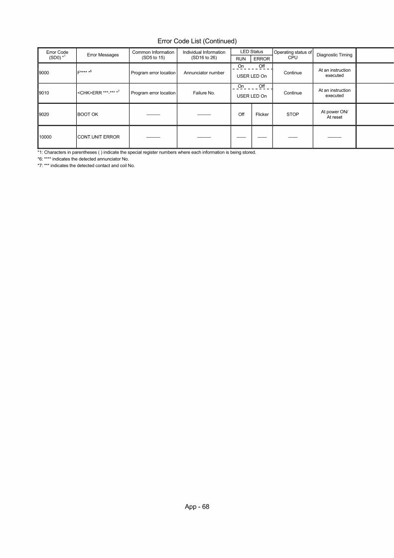
App - 68
Error Code List (Continued)
LED Status Error Code (SD0) *1 Error Messages Common Information
(SD5 to 15) Individual Information
(SD16 to 26) RUN ERROROperating status of
CPU Diagnostic Timing
On Off 9000 F**** *6 Program error location Annunciator number
USER LED On Continue At an instruction
executed
On Off 9010 <CHK>ERR ***-*** *7 Program error location Failure No.
USER LED On Continue At an instruction
executed
9020 BOOT OK ——— ——— Off Flicker STOP At power ON/ At reset
10000 CONT.UNIT ERROR ——— ——— —— —— —— ———
*1: Characters in parentheses ( ) indicate the special register numbers where each information is being stored. *6: **** indicates the detected annunciator No. *7: *** indicates the detected contact and coil No.

App - 69
Error Code (SD0) *1 Error Contents and Cause Corrective Action Applicable
CPU
9000 Annunciator F was turned ON Read the individual information of the error using a peripheral device, and check the program of its numerical value (annunciator number).
9010 An error was detected by the CHK instruction. Read the individual information of the error using a peripheral device, and check the program of its numerical value (error number).
9020 Storage of data onto ROM was completed normally in automatic write to standard ROM. (BOOT LED also flickers.)
Set the parameter valid drive to the standard ROM. Then, switch power on again and perform boot operation from the standard ROM.
QCPU function Ver. B or
later
10000 An error occurred in the CPU module other than the QCPU. Check the details of the generated error by software package of applicable CPU module.
QCPU function Ver. B or
later *1: Characters in parentheses ( ) indicate the special register numbers where each information is being stored.
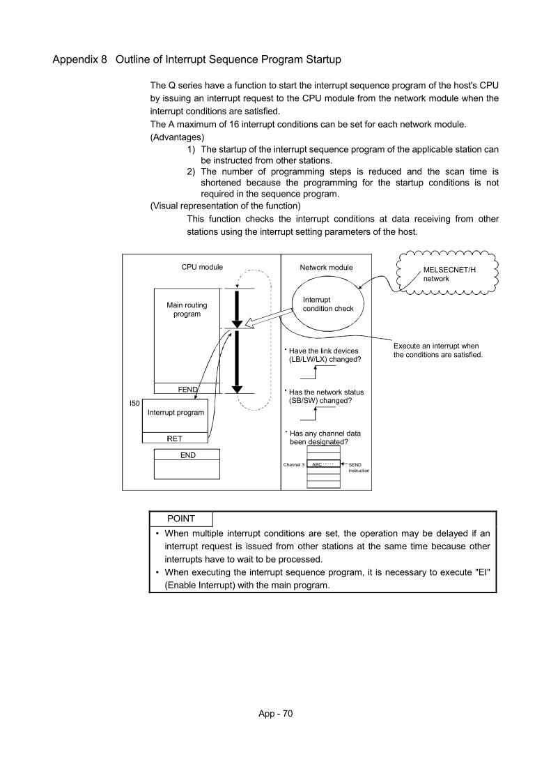
App - 70
Appendix 8 Outline of Interrupt Sequence Program Startup
The Q series have a function to start the interrupt sequence program of the host's CPU by issuing an interrupt request to the CPU module from the network module when the interrupt conditions are satisfied. The A maximum of 16 interrupt conditions can be set for each network module. (Advantages)
1) The startup of the interrupt sequence program of the applicable station can be instructed from other stations.
2) The number of programming steps is reduced and the scan time is shortened because the programming for the startup conditions is not required in the sequence program.
(Visual representation of the function) This function checks the interrupt conditions at data receiving from other stations using the interrupt setting parameters of the host.
END
IRET
Interrupt program
Network module
Interruptcondition check
Execute an interrupt whenthe conditions are satisfied.
MELSECNET/Hnetwork
FEND
Main routingprogram
CPU module
I50
Have the link devices(LB/LW/LX) changed?
Has any channel databeen designated?
Channel 3 SENDinstruction
ABC
Has the network status(SB/SW) changed?
POINT
• When multiple interrupt conditions are set, the operation may be delayed if an interrupt request is issued from other stations at the same time because other interrupts have to wait to be processed.
• When executing the interrupt sequence program, it is necessary to execute "EI" (Enable Interrupt) with the main program.
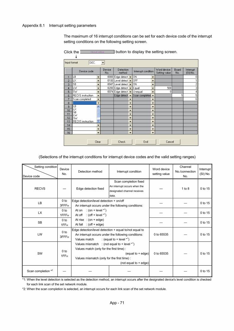
App - 71
Appendix 8.1 Interrupt setting parameters
The maximum of 16 interrupt conditions can be set for each device code of the interrupt setting conditions on the following setting screen.
button to display the setting screen.Click the
(Selections of the interrupt conditions for interrupt device codes and the valid setting ranges)
Setting condition
Device code
Device No.
Detection method Interrupt condition Word device setting value
Channel No./connection
No.
Interrupt (SI) No.
RECVS — Edge detection fixed
Scan completion fixed An interrupt occurs when the
designated channel receives
data.
— 1 to 8 0 to 15
LB 0 to
3FFFH — — 0 to 15
LX 0 to
1FFFH — — 0 to 15
SB 0 to
1FFH
Edge detection/level detection + on/off An interrupt occurs under the following conditions: At on : (on + level *1) At off : (off + level *1) At rise : (on + edge) At fall : (off + edge) — — 0 to 15
LW 0 to
3FFFH 0 to 65535 — 0 to 15
SW 0 to
1FFH
Edge detection/level detection + equal to/not equal to An interrupt occurs under the following conditions: Values match : (equal to + level *1) Values mismatch : (not equal to + level *1) Values match (only for the first time) :
(equal to + edge)Values mismatch (only for the first time) :
(not equal to + edge)
0 to 65535 — 0 to 15
Scan completion *2 — — — — — 0 to 15
*1: When the level detection is selected as the detection method, an interrupt occurs after the designated device's level condition is checked for each link scan of the set network module.
*2: When the scan completion is selected, an interrupt occurs for each link scan of the set network module.
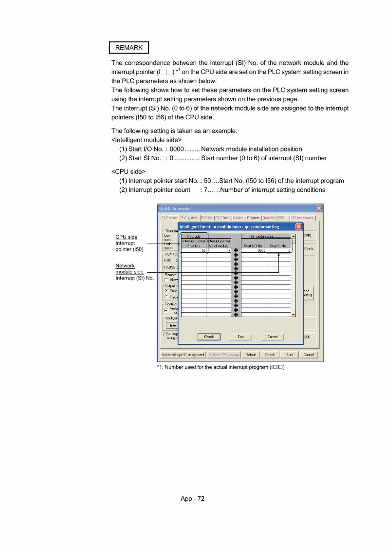
App - 72
REMARK
The correspondence between the interrupt (SI) No. of the network module and the interrupt pointer (I ) *1 on the CPU side are set on the PLC system setting screen in the PLC parameters as shown below. The following shows how to set these parameters on the PLC system setting screen using the interrupt setting parameters shown on the previous page. The interrupt (SI) No. (0 to 6) of the network module side are assigned to the interrupt pointers (I50 to I56) of the CPU side.
The following setting is taken as an example. <Intelligent module side>
(1) Start I/O No. : 0000......... Network module installation position (2) Start SI No. : 0 ............... Start number (0 to 6) of interrupt (SI) number
<CPU side>
(1) Interrupt pointer start No. : 50….Start No. (I50 to I56) of the interrupt program (2) Interrupt pointer count : 7……Number of interrupt setting conditions
CPU sideInterrupt pointer (I50)
Network module sideInterrupt (SI) No.
*1: Number used for the actual interrupt program (I )
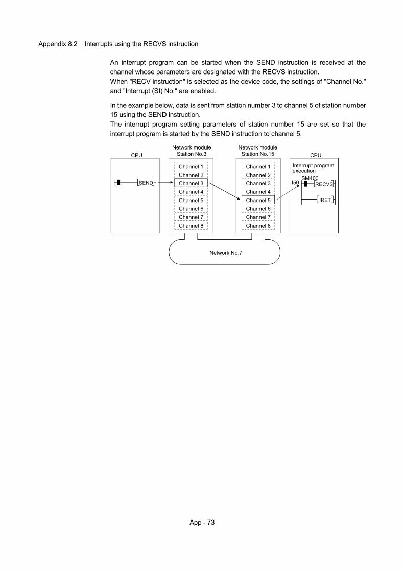
App - 73
Appendix 8.2 Interrupts using the RECVS instruction
An interrupt program can be started when the SEND instruction is received at the channel whose parameters are designated with the RECVS instruction. When "RECV instruction" is selected as the device code, the settings of "Channel No." and "Interrupt (SI) No." are enabled.
In the example below, data is sent from station number 3 to channel 5 of station number 15 using the SEND instruction. The interrupt program setting parameters of station number 15 are set so that the interrupt program is started by the SEND instruction to channel 5.
CPUNetwork module
Station No.3Network module
Station No.15 CPU
Network No.7
Interrupt program execution
IRET
I50
Channel 1Channel 2Channel 3Channel 4Channel 5Channel 6Channel 7Channel 8
Channel 1Channel 2Channel 3Channel 4Channel 5Channel 6Channel 7Channel 8
SEND RECVSSM400
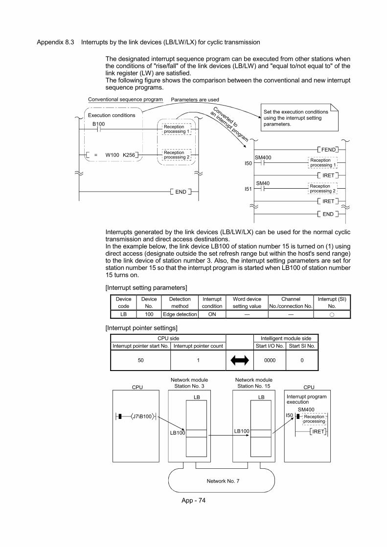
App - 74
Appendix 8.3 Interrupts by the link devices (LB/LW/LX) for cyclic transmission
The designated interrupt sequence program can be executed from other stations when the conditions of "rise/fall" of the link devices (LB/LW) and "equal to/not equal to" of the link register (LW) are satisfied. The following figure shows the comparison between the conventional and new interrupt sequence programs.
Reception processing 1
K256 Reception processing 2
Execution conditions
B100
END
FEND
Reception processing 1
SM400
IRET
Reception processing 2
SM40
IRET
END
Conventional sequence program
Set the execution conditions using the interrupt setting parameters.
I50
I51
Converted to
an interrupt program
Parameters are used
= W100
Interrupts generated by the link devices (LB/LW/LX) can be used for the normal cyclic transmission and direct access destinations. In the example below, the link device LB100 of station number 15 is turned on (1) using direct access (designate outside the set refresh range but within the host's send range) to the link device of station number 3. Also, the interrupt setting parameters are set for station number 15 so that the interrupt program is started when LB100 of station number 15 turns on.
[Interrupt setting parameters]
Device code
Device No.
Detection method
Interrupt condition
Word device setting value
Channel No./connection No.
Interrupt (SI) No.
LB 100 Edge detection ON — —
[Interrupt pointer settings] CPU side Intelligent module side
Interrupt pointer start No. Interrupt pointer count Start I/O No. Start SI No.
50 1 0000 0
CPUNetwork module
Station No. 3Network moduleStation No. 15 CPU
Network No. 7
Interrupt program execution
Receptionprocessing
IRET
I50J7\B100
LB100 LB100
LB LB
SM400

App - 75
REMARK
(1) When the sequence program executes at high speed, the scan time may take longer because the execution time of the interrupt program affects the performance of the interrupt program.
(2) When multiple interrupts occur at the same time, the operation delay may occur.
(3) This function cannot be used during offline or online testing.
(4) Do not start the interrupt sequence program by the designated device's rise (PLS
instruction, etc.) and fall (PLF instruction, etc.); the change in the device may not be read.
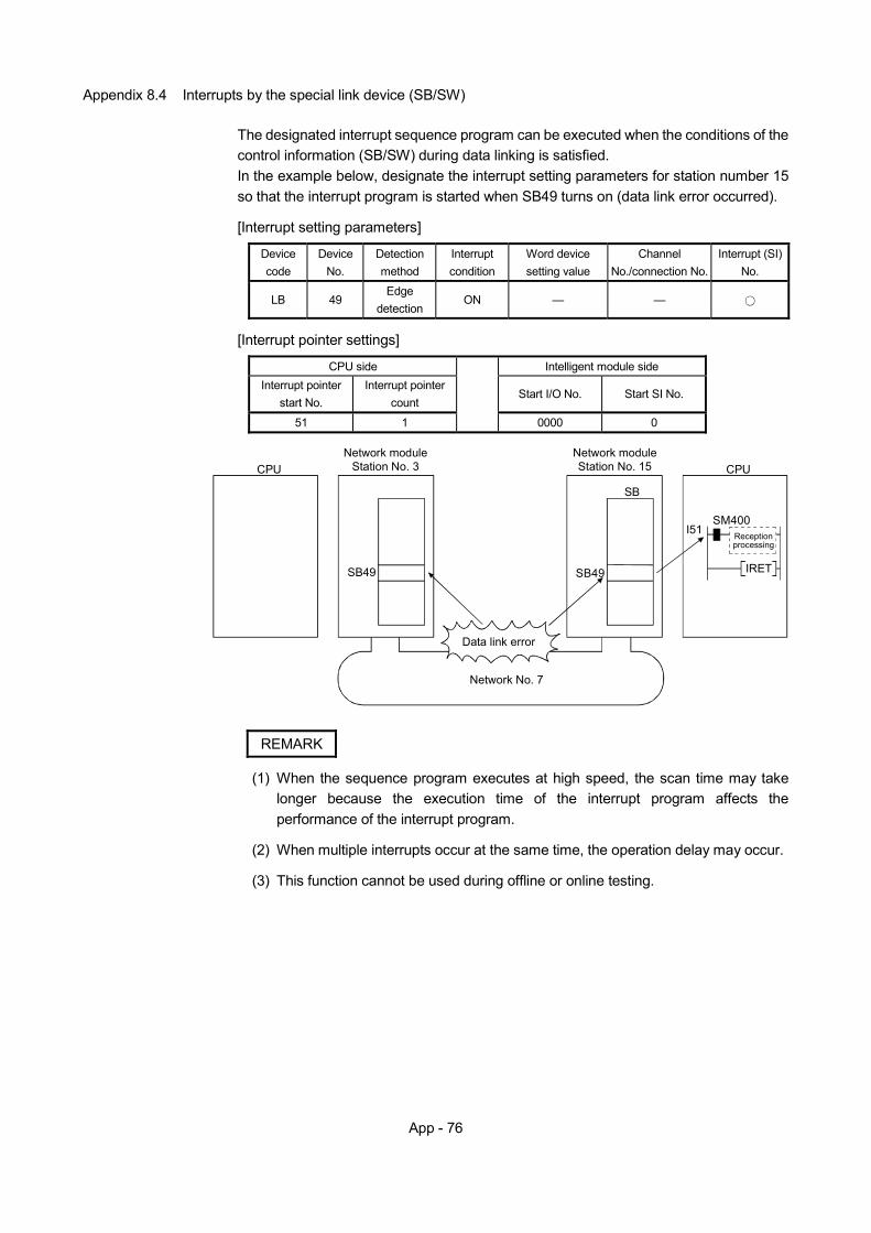
App - 76
Appendix 8.4 Interrupts by the special link device (SB/SW)
The designated interrupt sequence program can be executed when the conditions of the control information (SB/SW) during data linking is satisfied. In the example below, designate the interrupt setting parameters for station number 15 so that the interrupt program is started when SB49 turns on (data link error occurred).
[Interrupt setting parameters]
Device code
Device No.
Detection method
Interrupt condition
Word device setting value
Channel No./connection No.
Interrupt (SI) No.
LB 49 Edge
detection ON — —
[Interrupt pointer settings]
CPU side Intelligent module side
Interrupt pointer start No.
Interrupt pointer count
Start I/O No. Start SI No.
51 1
0000 0
CPUNetwork module
Station No. 3Network moduleStation No. 15 CPU
Network No. 7
Receptionprocessing
IRET
I51
SB49 SB49
Data link error
SB
SM400
REMARK
(1) When the sequence program executes at high speed, the scan time may take longer because the execution time of the interrupt program affects the performance of the interrupt program.
(2) When multiple interrupts occur at the same time, the operation delay may occur.
(3) This function cannot be used during offline or online testing.
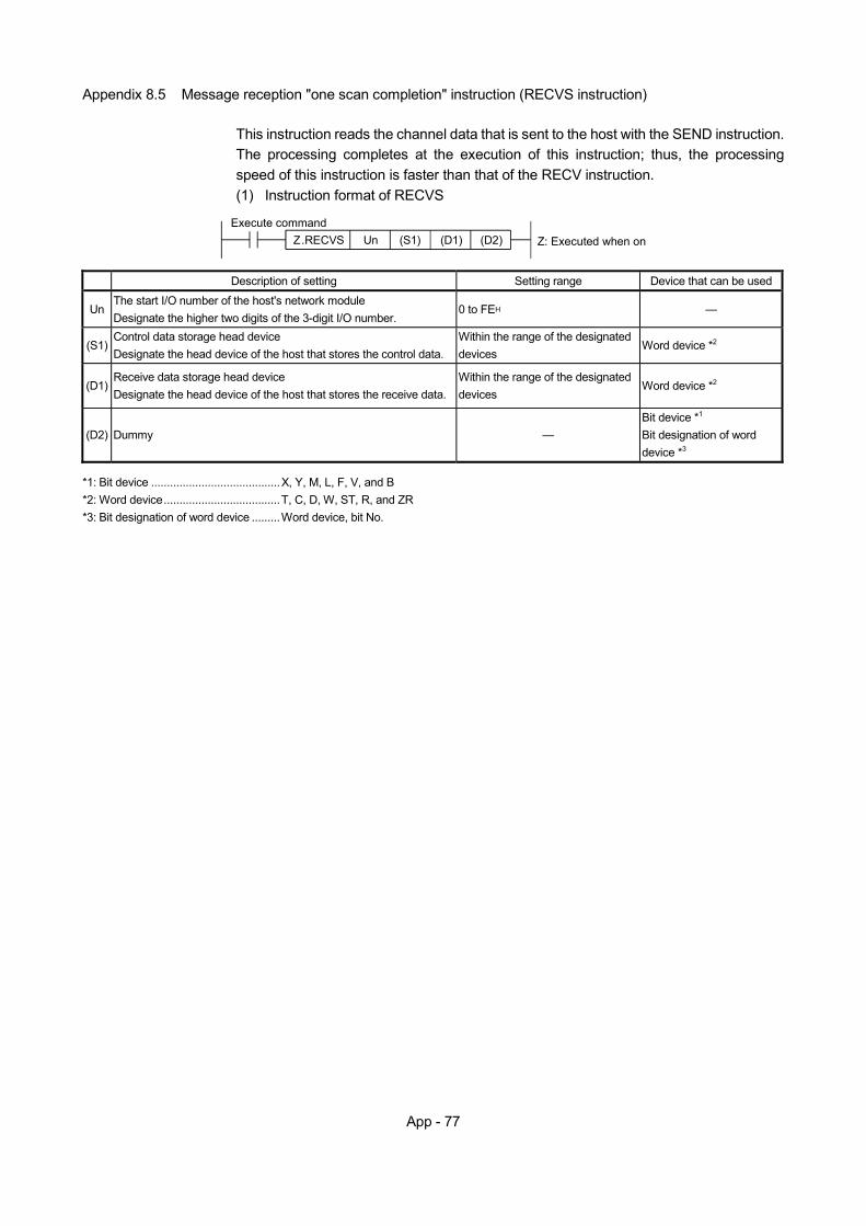
App - 77
Appendix 8.5 Message reception "one scan completion" instruction (RECVS instruction)
This instruction reads the channel data that is sent to the host with the SEND instruction. The processing completes at the execution of this instruction; thus, the processing speed of this instruction is faster than that of the RECV instruction. (1) Instruction format of RECVS
Z.RECVS Z: Executed when onUnExecute command
(S1) (D1) (D2)
Description of setting Setting range Device that can be used
Un The start I/O number of the host's network module Designate the higher two digits of the 3-digit I/O number.
0 to FEH —
(S1) Control data storage head device Designate the head device of the host that stores the control data.
Within the range of the designated devices
Word device *2
(D1) Receive data storage head device Designate the head device of the host that stores the receive data.
Within the range of the designated devices
Word device *2
(D2) Dummy — Bit device *1
Bit designation of word device *3
*1: Bit device .........................................X, Y, M, L, F, V, and B *2: Word device.....................................T, C, D, W, ST, R, and ZR *3: Bit designation of word device .........Word device, bit No.
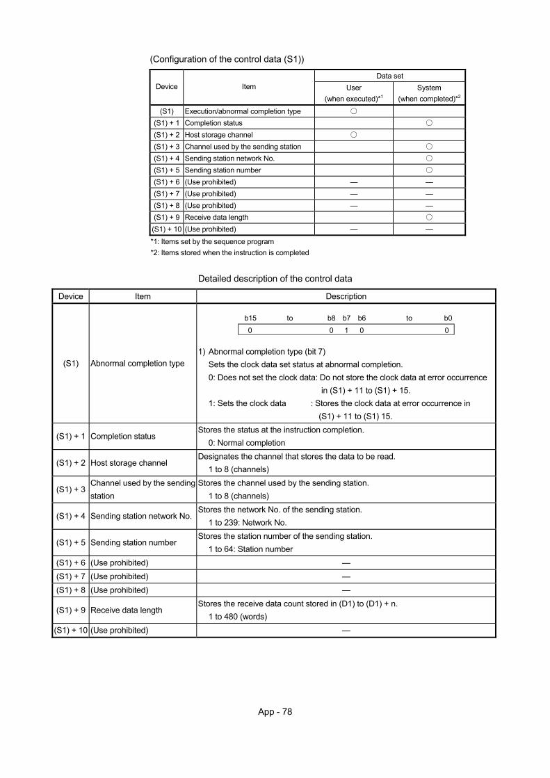
App - 78
(Configuration of the control data (S1))
Data set
Device Item User (when executed)*1
System (when completed)*2
(S1) Execution/abnormal completion type (S1) + 1 Completion status (S1) + 2 Host storage channel (S1) + 3 Channel used by the sending station (S1) + 4 Sending station network No. (S1) + 5 Sending station number (S1) + 6 (Use prohibited) — — (S1) + 7 (Use prohibited) — — (S1) + 8 (Use prohibited) — — (S1) + 9 Receive data length (S1) + 10 (Use prohibited) — —
*1: Items set by the sequence program *2: Items stored when the instruction is completed
Detailed description of the control data
Device Item Description
(S1) Abnormal completion type
0 10 0 0
b15 b8 b7 b6 b0toto
1) Abnormal completion type (bit 7)
Sets the clock data set status at abnormal completion. 0: Does not set the clock data: Do not store the clock data at error occurrence
in (S1) + 11 to (S1) + 15. 1: Sets the clock data : Stores the clock data at error occurrence in
(S1) + 11 to (S1) 15.
(S1) + 1 Completion status Stores the status at the instruction completion.
0: Normal completion
(S1) + 2 Host storage channel Designates the channel that stores the data to be read.
1 to 8 (channels)
(S1) + 3 Channel used by the sending station
Stores the channel used by the sending station. 1 to 8 (channels)
(S1) + 4 Sending station network No. Stores the network No. of the sending station.
1 to 239: Network No.
(S1) + 5 Sending station number Stores the station number of the sending station.
1 to 64: Station number (S1) + 6 (Use prohibited) — (S1) + 7 (Use prohibited) — (S1) + 8 (Use prohibited) —
(S1) + 9 Receive data length Stores the receive data count stored in (D1) to (D1) + n.
1 to 480 (words) (S1) + 10 (Use prohibited) —
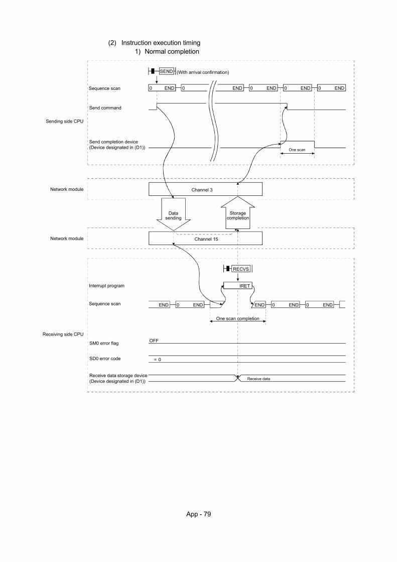
App - 79
(2) Instruction execution timing
1) Normal completion
0 ENDSequence scan 0 END 0 END 0 END 0 END
Send command
SEND (With arrival confirmation)
One scan
Sending side CPU
Send completion device(Device designated in (D1))
Network module
Network module Channel 15
Channel 3
Datasending
Storagecompletion
Sequence scan 0 END0 END
SM0 error flag
RECVS
END
Receive data
Receiving side CPU
IRET
0 END
One scan completion
OFF
= 0SD0 error code
END
Receive data storage device (Device designated in (D1))
Interrupt program
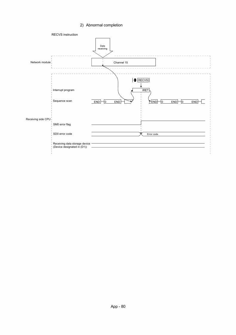
App - 80
2) Abnormal completion
Network module Channel 15
Datareceiving
Sequence scan 0 END0 END
SM0 error flag
RECVS
END
Receiving side CPU
IRET
0 END
SD0 error code Error code
END
Receiving data storage device (Device designated in (D1))
Interrupt program
RECVS instruction
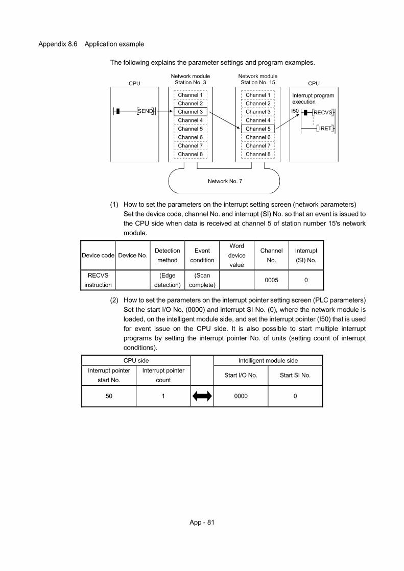
App - 81
Appendix 8.6 Application example
The following explains the parameter settings and program examples.
CPUNetwork module
Station No. 3 CPUNetwork moduleStation No. 15
Network No. 7
Interrupt program execution
IRET
I50
Channel 1
SEND RECVS
Channel 2Channel 3Channel 4Channel 5Channel 6Channel 7Channel 8
Channel 1Channel 2Channel 3Channel 4Channel 5Channel 6Channel 7Channel 8
(1) How to set the parameters on the interrupt setting screen (network parameters)
Set the device code, channel No. and interrupt (SI) No. so that an event is issued to the CPU side when data is received at channel 5 of station number 15's network module.
Device code Device No. Detection method
Event condition
Word device value
Channel No.
Interrupt (SI) No.
RECVS instruction
(Edge
detection) (Scan
complete) 0005 0
(2) How to set the parameters on the interrupt pointer setting screen (PLC parameters)
Set the start I/O No. (0000) and interrupt SI No. (0), where the network module is loaded, on the intelligent module side, and set the interrupt pointer (I50) that is used for event issue on the CPU side. It is also possible to start multiple interrupt programs by setting the interrupt pointer No. of units (setting count of interrupt conditions).
CPU side Intelligent module side
Interrupt pointer start No.
Interrupt pointer count
Start I/O No. Start SI No.
50 1 0000 0
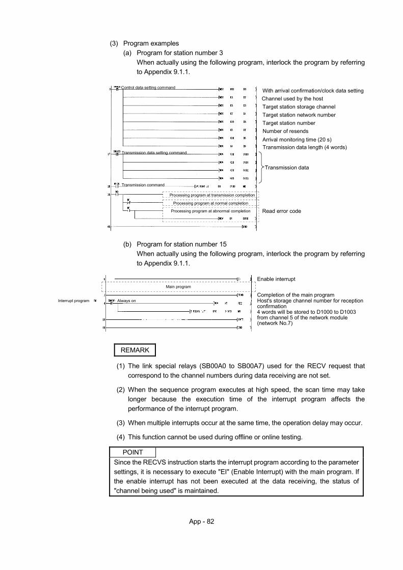
App - 82
(3) Program examples
(a) Program for station number 3 When actually using the following program, interlock the program by referring to Appendix 9.1.1.
Control data setting command With arrival confirmation/clock data setting
Channel used by the hostTarget station storage channel
Arrival monitoring time (20 s)
Transmission data setting command
Read error code
Transmission command
Transmission data
Transmission data length (4 words)
Number of resendsTarget station numberTarget station network number
Processing program at transmission completion
Processing program at normal completion
Processing program at abnormal completion
(b) Program for station number 15
When actually using the following program, interlock the program by referring to Appendix 9.1.1.
Always on
Enable interrupt
Completion of the main programMain program
4 words will be stored to D1000 to D1003 from channel 5 of the network module (network No.7)
Host's storage channel number for reception confirmation
Interrupt program
REMARK
(1) The link special relays (SB00A0 to SB00A7) used for the RECV request that correspond to the channel numbers during data receiving are not set.
(2) When the sequence program executes at high speed, the scan time may take
longer because the execution time of the interrupt program affects the performance of the interrupt program.
(3) When multiple interrupts occur at the same time, the operation delay may occur.
(4) This function cannot be used during offline or online testing.
POINT
Since the RECVS instruction starts the interrupt program according to the parameter settings, it is necessary to execute "EI" (Enable Interrupt) with the main program. If the enable interrupt has not been executed at the data receiving, the status of "channel being used" is maintained.
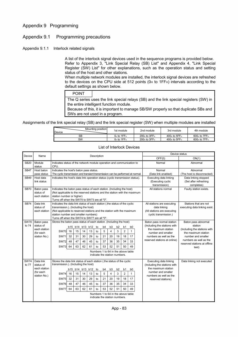
App - 83
Appendix 9 Programming
Appendix 9.1 Programming precautions
Appendix 9.1.1 Interlock related signals
A list of the interlock signal devices used in the sequence programs is provided below. Refer to Appendix 3, "Link Special Relay (SB) List" and Appendix 4, "Link Special Register (SW) List" for other explanations, such as the operation status and setting status of the host and other stations. When multiple network modules are installed, the interlock signal devices are refreshed to the devices on the CPU side at 512 points (0H to 1FFH) intervals according to the default settings as shown below.
POINT
The Q series uses the link special relays (SB) and the link special registers (SW) in the entire intelligent function module. Because of this, it is important to manage SB/SW properly so that duplicate SBs and SWs are not used in a program.
Assignments of the link special relay (SB) and the link special register (SW) when multiple modules are installed
Mounting positionDevice 1st module 2nd module 3rd module 4th module
SB 0H to 1FFH 200H to 3FFH 400H to 5FFH 600H to 7FFH SW 0H to 1FFH 200H to 3FFH 400H to 5FFH 600H to 7FFH
List of Interlock Devices
Device status Device Name Description
OFF(0) ON(1) SB20 Module
status Indicates status of the network module operation and communication to CPU.
Normal Abnormal
SB47 Host baton pass status
Indicates the host's baton pass status. The cyclic transmission and transient transmission can be performed at normal.
Normal (Data link enabled)
Abnormal (The host is disconnected)
SB49 Host data link status
Indicates the host's data link operation status (cyclic transmission status). Executing data linking (Executing cyclic
transmission)
Data linking stopped (Set after refreshing
completes) SB70 Baton pass
status of each station
Indicates the baton pass status of each station. (Including the host) (Not applicable to the reserved stations and the station with the maximum station number or higher) Turns off when the SW70 to SW73 are all "0".
All stations normal Faulty station exists.
SB74 Data link status of each station
Indicates the data link status of each station (.the status of the cyclic transmission.). (Including the host) (Not applicable to reserved stations and the station with the maximum station number and smaller numbers) Turns off when the SW74 to SW77 are all "0".
All stations are executing data linking
(All stations are executing cyclic transmission.)
Stations that are not executing data linking exist.
SW70 to 74
Baton pass status of each station (for each station No.)
Stores the baton pass status of each station. (Including the host)
16
32
48
64
15 14 13 5 4 3 2 1
31 30
47 46
63 62
29
45
61
21 20 19 18 17
37 36 35 34 33
53 52 51 50 49
to
to
to
to
b15 b14 b13 b12 b4 b3 b2 b1 b0SW70
SW71
SW72
SW73
Numbers 1 to 64 in the above table indicate the station numbers.
to
Baton pass normal station (Including the stations with
the maximum station number and smaller
numbers as well as the reserved stations at online)
Baton pass abnormal station
(Including the stations with the maximum station number and smaller
numbers as well as the reserved stations at offline
test)
SW74 to 77
Data link status of each station (for each station No.)
Stores the data link status of each station (.the status of the cyclic transmission.). (Including the host)
16
32
48
64
15 14 13 5 4 3 2 1
31 30
47 46
63 62
29
45
61
21 20 19 18 17
37 36 35 34 33
53 52 51 50 49
to
to
to
to
b15 b14 b13 b12 b4 b3 b2 b1 b0SW74
SW75
SW76
SW77
Numbers 1 to 64 in the above table indicate the station numbers.
to
Executing data linking (Including the stations with
the maximum station number and smaller
numbers as well as the reserved stations)
Data linking not executed
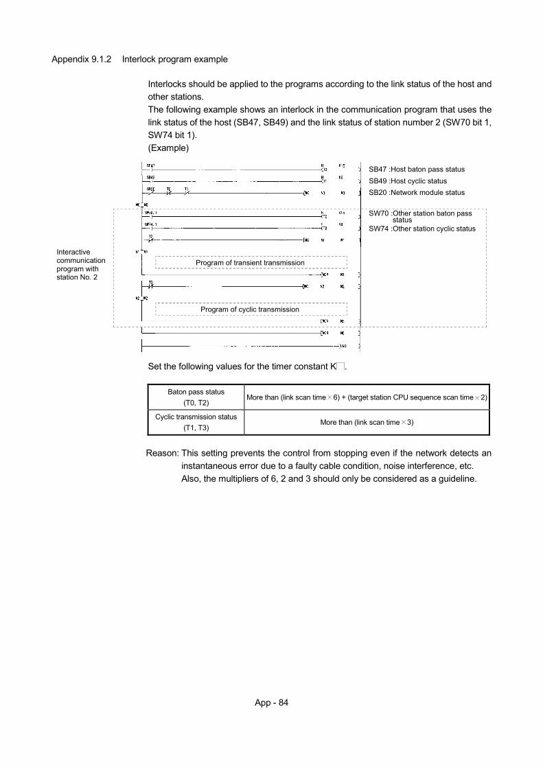
App - 84
Appendix 9.1.2 Interlock program example
Interlocks should be applied to the programs according to the link status of the host and other stations. The following example shows an interlock in the communication program that uses the link status of the host (SB47, SB49) and the link status of station number 2 (SW70 bit 1, SW74 bit 1). (Example)
SB49 :Host cyclic statusSB47 :Host baton pass status
SB20 :Network module status
SW70 :Other station baton pass statusSW74 :Other station cyclic status
Interactive communication program with station No. 2
Program of transient transmission
Program of cyclic transmission
Set the following values for the timer constant K .
Baton pass status
(T0, T2) More than (link scan time 6) + (target station CPU sequence scan time 2)
Cyclic transmission status (T1, T3)
More than (link scan time 3)
Reason: This setting prevents the control from stopping even if the network detects an
instantaneous error due to a faulty cable condition, noise interference, etc. Also, the multipliers of 6, 2 and 3 should only be considered as a guideline.
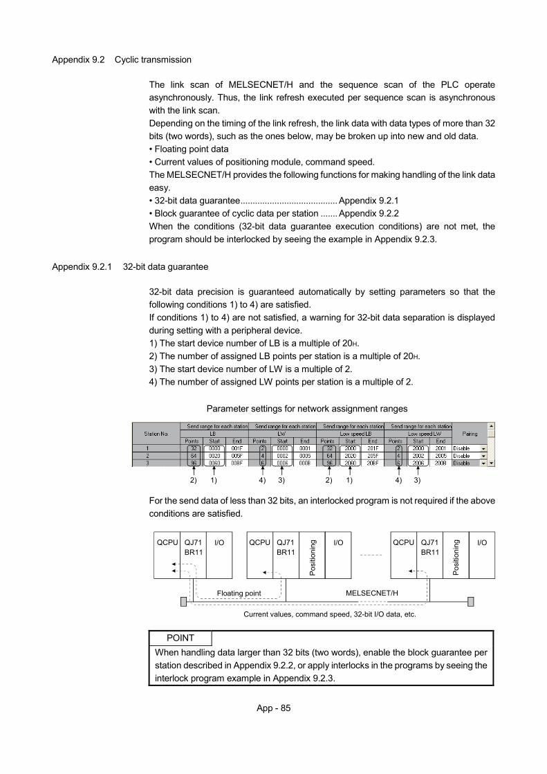
App - 85
Appendix 9.2 Cyclic transmission
The link scan of MELSECNET/H and the sequence scan of the PLC operate asynchronously. Thus, the link refresh executed per sequence scan is asynchronous with the link scan. Depending on the timing of the link refresh, the link data with data types of more than 32 bits (two words), such as the ones below, may be broken up into new and old data. • Floating point data • Current values of positioning module, command speed. The MELSECNET/H provides the following functions for making handling of the link data easy. • 32-bit data guarantee........................................ Appendix 9.2.1 • Block guarantee of cyclic data per station ....... Appendix 9.2.2 When the conditions (32-bit data guarantee execution conditions) are not met, the program should be interlocked by seeing the example in Appendix 9.2.3.
Appendix 9.2.1 32-bit data guarantee
32-bit data precision is guaranteed automatically by setting parameters so that the following conditions 1) to 4) are satisfied. If conditions 1) to 4) are not satisfied, a warning for 32-bit data separation is displayed during setting with a peripheral device. 1) The start device number of LB is a multiple of 20H. 2) The number of assigned LB points per station is a multiple of 20H. 3) The start device number of LW is a multiple of 2. 4) The number of assigned LW points per station is a multiple of 2.
Parameter settings for network assignment ranges
4)4) 2)2) 1) 3) 1) 3)
For the send data of less than 32 bits, an interlocked program is not required if the above conditions are satisfied.
QCPU QJ71BR11
I/O QCPU QJ71BR11
I/O
Pos
ition
ing QCPU QJ71
BR11I/O
Posi
tioni
ng
Floating point
Current values, command speed, 32-bit I/O data, etc.
MELSECNET/H
POINT
When handling data larger than 32 bits (two words), enable the block guarantee per station described in Appendix 9.2.2, or apply interlocks in the programs by seeing the interlock program example in Appendix 9.2.3.
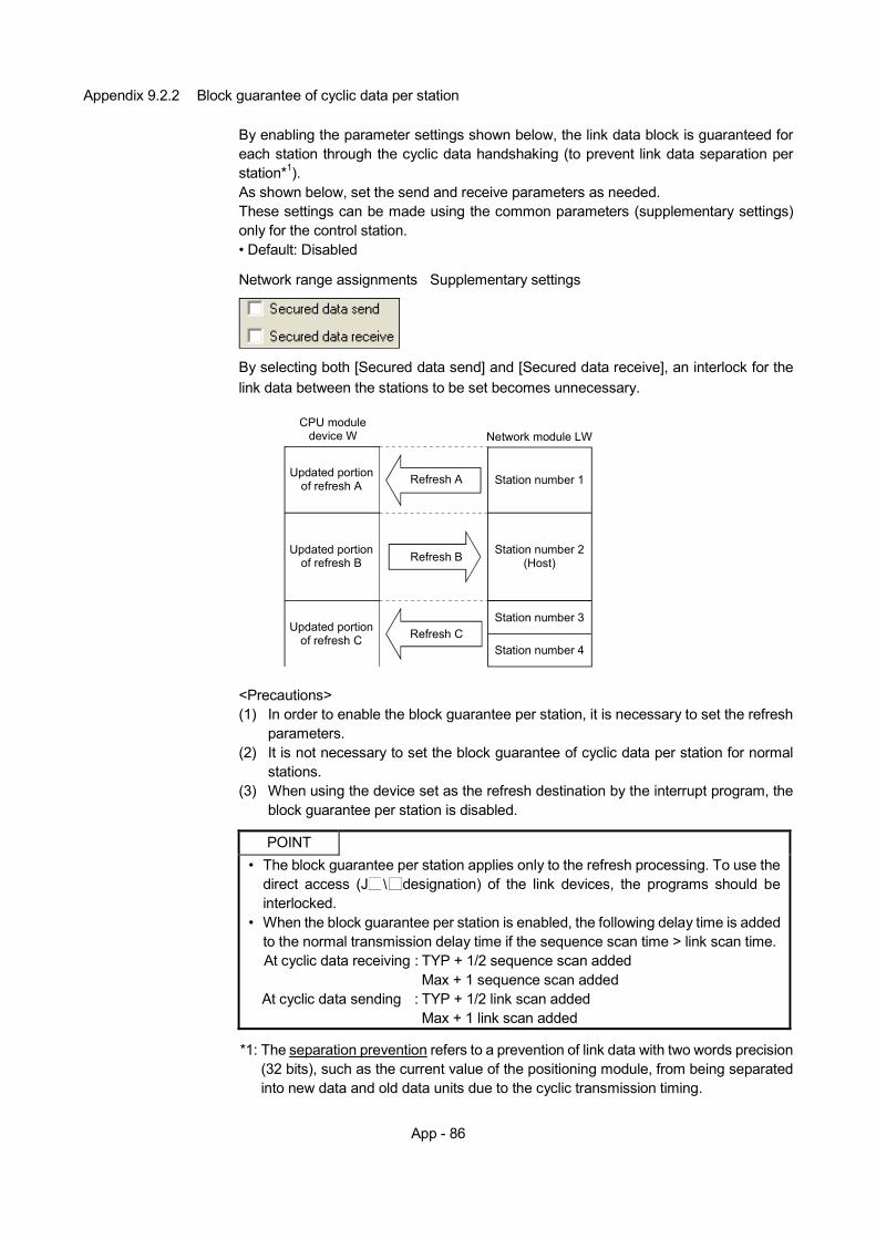
App - 86
Appendix 9.2.2 Block guarantee of cyclic data per station
By enabling the parameter settings shown below, the link data block is guaranteed for each station through the cyclic data handshaking (to prevent link data separation per station*1). As shown below, set the send and receive parameters as needed. These settings can be made using the common parameters (supplementary settings) only for the control station. • Default: Disabled
Network range assignments Supplementary settings
By selecting both [Secured data send] and [Secured data receive], an interlock for the link data between the stations to be set becomes unnecessary.
Network module LWCPU module
device W
Refresh A
Refresh B
Updated portionof refresh A
Refresh C
Updated portionof refresh B
Updated portionof refresh C
Station number 1
Station number 2(Host)
Station number 3
Station number 4
<Precautions> (1) In order to enable the block guarantee per station, it is necessary to set the refresh
parameters. (2) It is not necessary to set the block guarantee of cyclic data per station for normal
stations. (3) When using the device set as the refresh destination by the interrupt program, the
block guarantee per station is disabled.
POINT • The block guarantee per station applies only to the refresh processing. To use the
direct access (J designation) of the link devices, the programs should be interlocked.
• When the block guarantee per station is enabled, the following delay time is added to the normal transmission delay time if the sequence scan time > link scan time. At cyclic data receiving : TYP + 1/2 sequence scan added Max + 1 sequence scan added At cyclic data sending : TYP + 1/2 link scan added Max + 1 link scan added
*1: The separation prevention refers to a prevention of link data with two words precision
(32 bits), such as the current value of the positioning module, from being separated into new data and old data units due to the cyclic transmission timing.
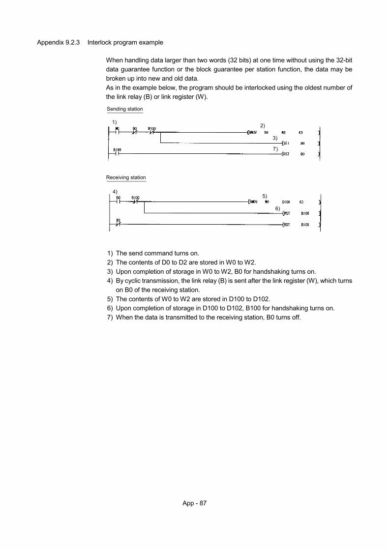
App - 87
Appendix 9.2.3 Interlock program example
When handling data larger than two words (32 bits) at one time without using the 32-bit data guarantee function or the block guarantee per station function, the data may be broken up into new and old data. As in the example below, the program should be interlocked using the oldest number of the link relay (B) or link register (W).
4)
Receiving station
6)
5)
1)
Sending station
2)
7)
3)
1) The send command turns on. 2) The contents of D0 to D2 are stored in W0 to W2. 3) Upon completion of storage in W0 to W2, B0 for handshaking turns on. 4) By cyclic transmission, the link relay (B) is sent after the link register (W), which turns
on B0 of the receiving station. 5) The contents of W0 to W2 are stored in D100 to D102. 6) Upon completion of storage in D100 to D102, B100 for handshaking turns on. 7) When the data is transmitted to the receiving station, B0 turns off.
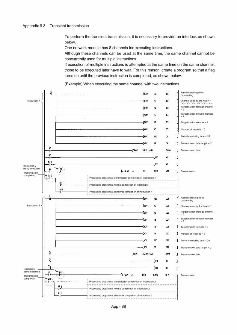
App - 88
Appendix 9.3 Transient transmission
To perform the transient transmission, it is necessary to provide an interlock as shown below. One network module has 8 channels for executing instructions. Although these channels can be used at the same time, the same channel cannot be concurrently used for multiple instructions. If execution of multiple instructions is attempted at the same time on the same channel, those to be executed later have to wait. For this reason, create a program so that a flag turns on until the previous instruction is completed, as shown below.
(Example) When executing the same channel with two instructions
Arrival checking/clock data setting
Channel used by the host = 1
Target station storage channel = 2
Target station network number = 7
Target station number = 2
Number of resends = 5
Arrival monitoring time = 20
Transmission data length = 2
Transmission data
Transmission
Arrival checking/clock data setting
Channel used by the host = 1
Target station storage channel = 3
Target station network number = 8
Target station number = 3
Number of resends = 5
Arrival monitoring time = 20
Transmission data length = 2
Transmission data
Transmission
Processing program at transmission completion of instruction 1
Processing program at normal completion of instruction 1
Processing program at abnormal completion of instruction 1
Processing program at transmission completion of instruction 2
Processing program at normal completion of instruction 2
Processing program at abnormal completion of instruction 2
Instruction 1
Instruction 2
Instruction 2 being executed
Transmission completion
Instruction 1 being executed
Transmission completion
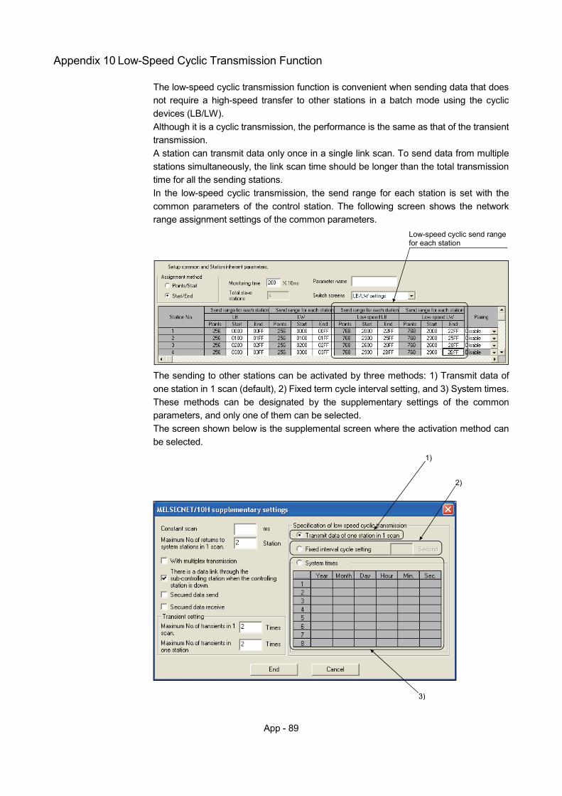
App - 89
Appendix 10 Low-Speed Cyclic Transmission Function
The low-speed cyclic transmission function is convenient when sending data that does not require a high-speed transfer to other stations in a batch mode using the cyclic devices (LB/LW). Although it is a cyclic transmission, the performance is the same as that of the transient transmission. A station can transmit data only once in a single link scan. To send data from multiple stations simultaneously, the link scan time should be longer than the total transmission time for all the sending stations. In the low-speed cyclic transmission, the send range for each station is set with the common parameters of the control station. The following screen shows the network range assignment settings of the common parameters.
Low-speed cyclic send range for each station
The sending to other stations can be activated by three methods: 1) Transmit data of one station in 1 scan (default), 2) Fixed term cycle interval setting, and 3) System times. These methods can be designated by the supplementary settings of the common parameters, and only one of them can be selected. The screen shown below is the supplemental screen where the activation method can be selected.
1)
2)
3)
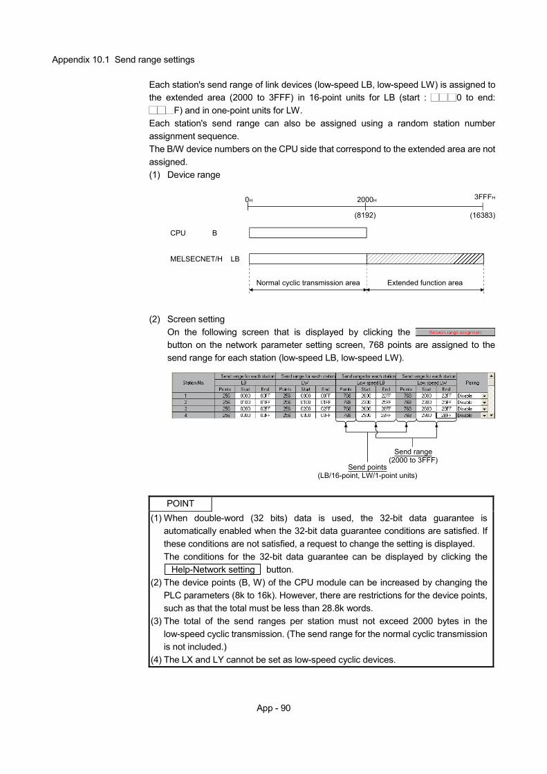
App - 90
Appendix 10.1 Send range settings
Each station's send range of link devices (low-speed LB, low-speed LW) is assigned to the extended area (2000 to 3FFF) in 16-point units for LB (start : 0 to end:
F) and in one-point units for LW. Each station's send range can also be assigned using a random station number assignment sequence. The B/W device numbers on the CPU side that correspond to the extended area are not assigned. (1) Device range
MELSECNET/H LB
CPU B
0H 2000H 3FFFH
(8192) (16383)
Normal cyclic transmission area Extended function area
(2) Screen setting
On the following screen that is displayed by clicking the button on the network parameter setting screen, 768 points are assigned to the send range for each station (low-speed LB, low-speed LW).
Send points(LB/16-point, LW/1-point units)
Send range(2000 to 3FFF)
POINT
(1) When double-word (32 bits) data is used, the 32-bit data guarantee is automatically enabled when the 32-bit data guarantee conditions are satisfied. If these conditions are not satisfied, a request to change the setting is displayed. The conditions for the 32-bit data guarantee can be displayed by clicking the Help-Network setting button.
(2) The device points (B, W) of the CPU module can be increased by changing the PLC parameters (8k to 16k). However, there are restrictions for the device points, such as that the total must be less than 28.8k words.
(3) The total of the send ranges per station must not exceed 2000 bytes in the low-speed cyclic transmission. (The send range for the normal cyclic transmission is not included.)
(4) The LX and LY cannot be set as low-speed cyclic devices.
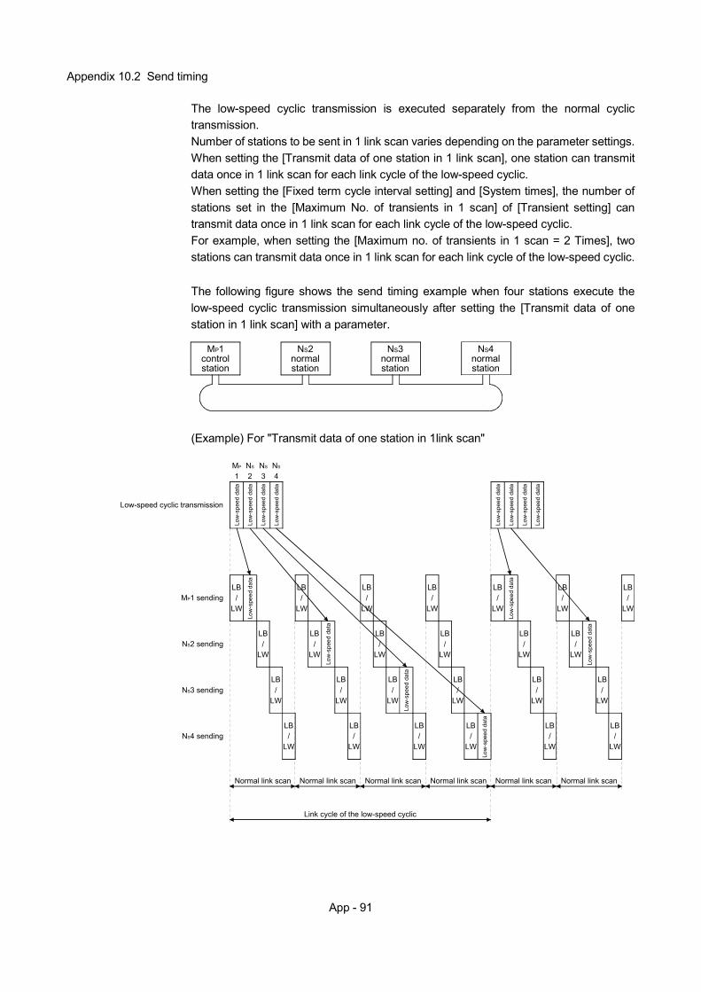
App - 91
Appendix 10.2 Send timing
The low-speed cyclic transmission is executed separately from the normal cyclic transmission. Number of stations to be sent in 1 link scan varies depending on the parameter settings. When setting the [Transmit data of one station in 1 link scan], one station can transmit data once in 1 link scan for each link cycle of the low-speed cyclic. When setting the [Fixed term cycle interval setting] and [System times], the number of stations set in the [Maximum No. of transients in 1 scan] of [Transient setting] can transmit data once in 1 link scan for each link cycle of the low-speed cyclic. For example, when setting the [Maximum no. of transients in 1 scan = 2 Times], two stations can transmit data once in 1 link scan for each link cycle of the low-speed cyclic.
The following figure shows the send timing example when four stations execute the low-speed cyclic transmission simultaneously after setting the [Transmit data of one station in 1 link scan] with a parameter.
NS2
normalstation
NS3normalstation
MP1controlstation
NS4normalstation
(Example) For "Transmit data of one station in 1link scan"
Low
-spe
ed d
ata
LB/
LW
LB/
LW
LB/
LW
LB/
LW
LB/
LW
LB/
LW
LB/
LW
LB/
LW
LB/
LW
LB/
LW
LB/
LW
LB/
LW
LB/
LW
LB/
LW
LB/
LW
LB/
LW
LB/
LW
LB/
LW
LB/
LW
LB/
LW
LB/
LW
LB/
LW
LB/
LW
LB/
LW
LB/
LWMP1 sending
NS2 sending
NS3 sending
NS4 sending
Low-speed cyclic transmission
MP
1NS
2NS
3NS
4
Normal link scan Normal link scan Normal link scan Normal link scan Normal link scan Normal link scan
Link cycle of the low-speed cyclic
Low
-spe
ed d
ata
Low
-spe
ed d
ata
Low
-spe
ed d
ata
Low
-spe
ed d
ata
Low
-spe
ed d
ata
Low
-spe
ed d
ata
Low
-spe
ed d
ata
Low
-spe
ed d
ata
Low
-spe
ed d
ata
Low
-spe
ed d
ata
Low
-spe
ed d
ata
Low
-spe
ed d
ata
Low
-spe
ed d
ata
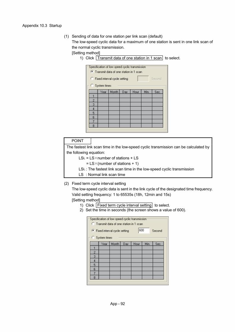
App - 92
Appendix 10.3 Startup
(1) Sending of data for one station per link scan (default) The low-speed cyclic data for a maximum of one station is sent in one link scan of the normal cyclic transmission. [Setting method]
1) Click Transmit data of one station in 1 scan to select.
POINT
The fastest link scan time in the low-speed cyclic transmission can be calculated by the following equation:
LSL = LS number of stations + LS = LS (number of stations + 1)
LSL : The fastest link scan time in the low-speed cyclic transmission LS : Normal link scan time
(2) Fixed term cycle interval setting
The low-speed cyclic data is sent in the link cycle of the designated time frequency. Valid setting frequency: 1 to 65535s (18h, 12min and 15s) [Setting method]
1) Click Fixed term cycle interval setting to select. 2) Set the time in seconds (the screen shows a value of 600).
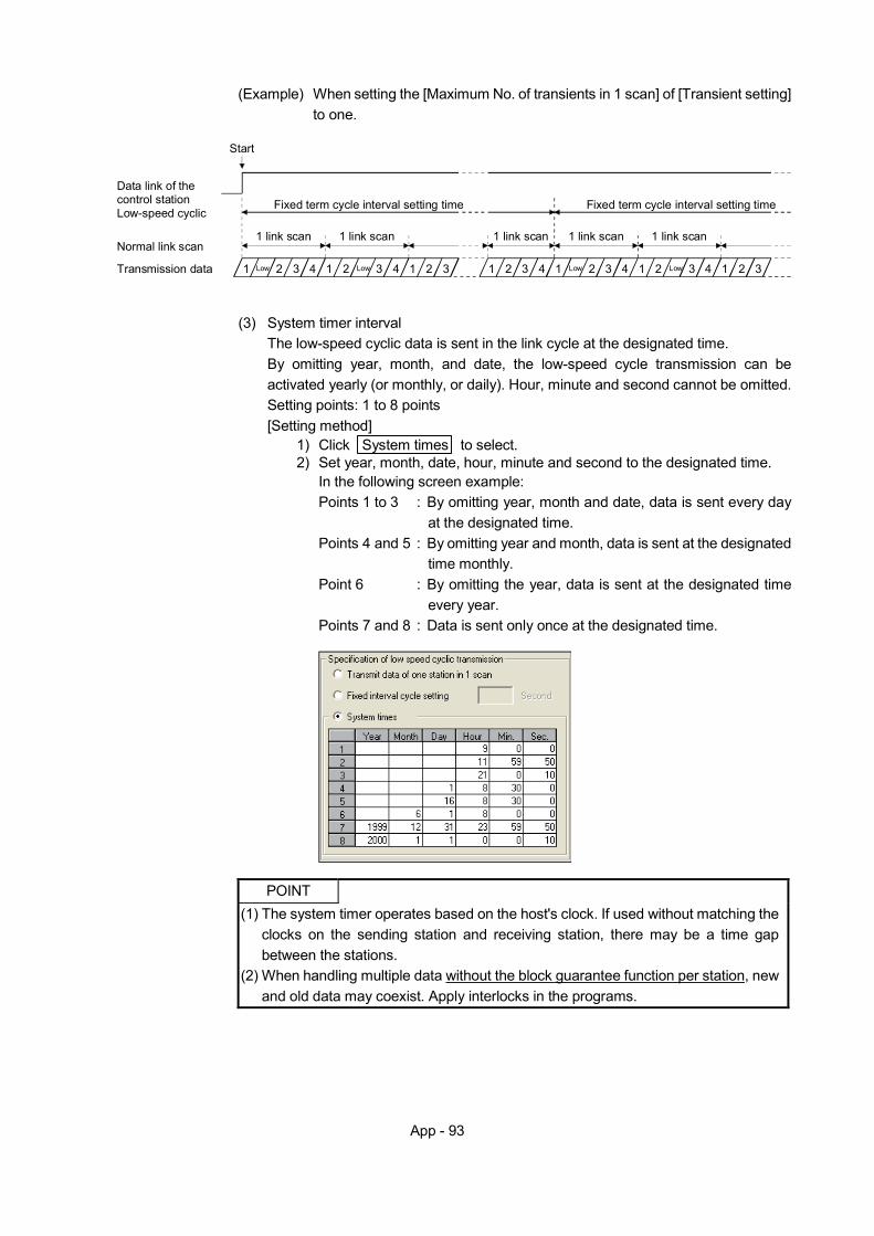
App - 93
(Example) When setting the [Maximum No. of transients in 1 scan] of [Transient setting]
to one.
Start
Fixed term cycle interval setting time
1 link scan
1
1 link scan
Low 2 3 4 1 2 3 4 1 2 3
Fixed term cycle interval setting time
1 link scan
1
1 link scan
2 3 4 1 2 3 4 1 2 3
1 link scan
1 2 3 4
Data link of thecontrol stationLow-speed cyclic
Normal link scan
Transmission data Low Low Low
(3) System timer interval
The low-speed cyclic data is sent in the link cycle at the designated time. By omitting year, month, and date, the low-speed cycle transmission can be activated yearly (or monthly, or daily). Hour, minute and second cannot be omitted. Setting points: 1 to 8 points [Setting method]
1) Click System times to select. 2) Set year, month, date, hour, minute and second to the designated time.
In the following screen example: Points 1 to 3 : By omitting year, month and date, data is sent every day
at the designated time. Points 4 and 5 : By omitting year and month, data is sent at the designated
time monthly. Point 6 : By omitting the year, data is sent at the designated time
every year. Points 7 and 8 : Data is sent only once at the designated time.
POINT
(1) The system timer operates based on the host's clock. If used without matching the clocks on the sending station and receiving station, there may be a time gap between the stations.
(2) When handling multiple data without the block guarantee function per station, new and old data may coexist. Apply interlocks in the programs.

App - 94
MEMO

MELSECNET/H course(Q-series)
Mitsubishi Programmable Logic Controller Training ManualMELSECNET/H course(Q-series)
ME
LSE
CN
ET
/H course(Q
-series)
Mitsubishi Programmable Logic Controller
Training Manual
MODEL
MODELCODE
SCHOOL-Q-NET10H-E
13JW52
SH(NA)-080619ENG-A(0601)MEE
Specifications subject to change without notice.
When exported from Japan, this manual does not require application to theMinistry of Economy, Trade and Industry for service transaction permission.
HEAD OFFICE : TOKYO BUILDING, 2-7-3 MARUNOUCHI, CHIYODA-KU, TOKYO 100-8310, JAPANNAGOYA WORKS : 1-14 , YADA-MINAMI 5-CHOME , HIGASHI-KU, NAGOYA , JAPAN