please read all instructional literature carefully and ... · for functional safety applications...
TRANSCRIPT

IM_ONE_Safety-06www.ueonline.com 1
Table of ContentsGeneral.........................................................................................................................................................................................................2
Mounting...................................................................................................................................................................................................2-3
Process Connections and Sensor Installation..........................................................................................................................................3-4
Wiring and Wiring Diagrams......................................................................................................................................................................4-7
Theory Of Operation................................................................................................................................................................................8-9Product Description..............................................................................................................................................................8Process Display Module........................................................................................................................................................8High Power Safety Relay Output...........................................................................................................................................8I Am Working (IAW)...............................................................................................................................................................9
Display Features and Diagnostics................................................................................................................................................................9Set Point Response...............................................................................................................................................................9Fault Conditions.....................................................................................................................................................................9
Programming.......................................................................................................................................................................................... .......Step 1: Prior to Programming............................................................................................................................................. Step 2: Entering the Programming Mode...........................................................................................................................Step 3: Exiting the Programming Mode.............................................................................................................................. Saving Programming Changes............................................................................................................................................Setting the Units of Measure..............................................................................................................................................Setting the SRO Mode.........................................................................................................................................................The Set Point.......................................................................................................................................................................The Deadband (Hysteresis)................................................................................................................................................Advanced Features.............................................................................................................................................................Resetting the Minimum & Maximum Readings....................................................................................................................Adjusting Display Offset......................................................................................................................................................Adjusting Span....................................................................................................................................................................Setting the Latch Mode (Manual Reset).............................................................................................................................Setting the Plugged Port Feature.......................................................................................................................................Setting the SRO Fault Monitor............................................................................................................................................Setting Filter.......................................................................................................................................................................Setting the Scale.................................................................................................................................................................Display Module Calibration.................................................................................................................................................
Zone Hazardous Locations Flameproof Gap and Joint Details...................................................................................................................15
One Series Safety Transmitter Fault Codes..........................................................................................................................................15-17Transmitter Power Supply and Load Limits...............................................................................................................................................18 Programming Flow Chart...........................................................................................................................................................................19Dimensional Drawings................................................................................................................................................................................20Sensor Options...........................................................................................................................................................................................21French Warning Translations................................................................................................................................................................22-23
One Series Safety Transmitter
Electronic Pressure and Temperature Loop-Powered Transmitter with High-Capacity Switching Model: 2SLP
UNITED ELECTR IC CONTROLS
Installation and Maintenance Instructions
IM_ONE_Safety-06
Please read all instructional literature carefully and thoroughly before starting. Refer to the final page for the listing of Recommended Practices, Liabilities and Warranties. For functional safety applications please refer to the safety manual section contained with this document. All Warnings are translated to French and can be found on pages 22 and 23.
9-159
1010101011111212121213131314141415

IM_ONE_Safety-06www.ueonline.com2
GENERALMISUSE OF THIS PRODUCT MAY CAUSE EXPLOSION AND PERSONAL INJURY. THESE INSTRUCTIONS MUST BE THOROUGHLY READ AND UNDERSTOOD BEFORE UNIT IS INSTALLED. SEE THE PRODUCT NAMEPLATE INFORMATION FOR SPECIFIC AGENCY CERTIFICATIONS APPLICABLE TO YOUR PRODUCT.
WARNING: EXPLOSION HAZARD - SUBSTITUTION OF COMPONENTS MAY IMPAIR SUITABILITY FOR USE IN HAZARDOUS LOCATIONS.
WARNING: In order to meet the Electromagnetic Compatibility requirements specified in EN61000-6-2: Immunity for Industrial Environments, external wiring must be run using cable with a grounded shield or cable run inside of a grounded metal conduit
WARNING: Interference from improperly shielded VFD’s (variable frequency drives) and motor controllers may cause nuisance trips.
WARNING: FOR ZONE HAZARDOUS LOCATIONS, ALL CABLE ENTRY DEVICES SHALL BE CERTIFIED IN TYPE OF EXPLOSION PROTECTION FLAMEPROOF ENCLOSURE “d” WITH AN IP66 RATING, SUITABLE FOR THE CONDITIONS OF USE AND CORRECTLY INSTALLED. IF CABLES AND CABLE GLANDS ARE NOT USED, A STOPPING BOX SHALL BE PROVIDED WITHIN 2” (5CM) OF THE ENCLOSURE. FLAMEPROOF JOINT AND GAP DETAILS ARE PROVIDED ON PAGE (15).
THE dEvICE HAS bEEN CERTIfIEd IN ACCORdANCE WITH THE APPLICAbLE REquIREMENTS Of THE fOLLOWING STANdARdS:
EN 60079-0: 2012+A11:2013 IEC 60079-0:Ed.6(2011-06) + Corr.1 (2012-01) + UL 1203:Ed.5, CSA 30:Ed.1 EN 60079-1: 2014 Corr.2 (2013-12) Rev. 2006, UL 60079-1:Ed.7, EN 60079-31: 2010 IEC 60079-1: 7th Edition, COR:1 CSA 60079-1:Ed.2 IEC 60079-31: 2nd Edition THIS EquIPMENT IS SuITAbLE fOR uSE IN NON-HAZARdOuS LOCATIONS ANd THE fOLLOWING HAZARdOuS LOCATIONS:
Class I, Div. 1, GRPS A, B, C, D Class II, Div. 1, GRPS E, F, G Class III Class I, Zone 1, AEx db IIC T5/T3* Class I, Zone 1, Ex d IIC T5/T3* Enclosure Type 4X, IP66 2SLP: -40ºC < TAMB < 70ºC (-40ºF to 158ºF)
* Straight pressure sensor models P06-P16 have a temperature class of T3, all others T5.
WARNING: EXPLOSION HAZARD – CONDUITS MUST BE SEALED WITHIN 2” (5CM) OF ENCLOSURE.
THIS EquIPMENT IS ATEX CERTIfIEd SuITAbLE fOR APPROPRIATE uSE IN GAS ANd duST ZONE 1 APPLICATIONS.
DEMKO 09 ATEX 0813748X II 2 G Ex db IIC T5/T3* Gb II 2 D Ex tb IIIC IP66 T90°C Db 2SLP: -40ºC < TAMB < 70ºC * Straight pressure sensor models P06-P16 have a temperature class of T3, all others T5.
THIS EquIPMENT IS IECEx CERTIfIEd, SuITAbLE fOR APPROPRIATE uSE IN GAS ANd duST ZONE 1 APPLICATIONS.
IECEx UL 08.0017 I 2 G Ex db IIC T5/T3* Gb II 2 D Ex tb IIIC IP66 T90°C Db 2SLP: -40ºC < TAMB < 70ºC * Straight pressure sensor models P06-P16 have a temperature class of T3, all others T5.
ALLOWABLE TRANSPORTATION AND STORAGE CONDITIONS: -40 TO 85°C
MOuNTINGTools Required: Hex Driver for mounting bolts; 4 mounting bolts (1/4” Max.) Please refer to the Dimensional Drawings on page 20NOTE: optional surface and pipe mounting kit is available - order part no. 6361-704. See page 20.
BEFORE INSTALLING, CHECK THE SENSOR MODEL SELECTED FOR COMPATIBILITY TO THE PROCESS MEDIA IN CONTACT WITH THE SENSOR AND WETTED PARTS.

IM_ONE_Safety-06www.ueonline.com 3
IN ALL APPLICATIONS, SECURE THE ENCLOSURE AS DETAILED BELOW. DO NOT MOUNT VIA THE PROCESS CONNECTION ONLY. Mount the unit using the four (4) 1/4” clearance holes in the enclosure base. Plumb sensor to the process port. See page 20 for dimensions.
Ensure the process connection is sealed to the process port to prevent leakage. Care should be taken to minimize effects of shock and vibration.
NOTE: To prevent thermal cycling effects on the enclosure, the One Series Safety Transmitter should be protected from direct sunlight and rain in outdoor installations using a shroud. The digital display is optimized for viewing from the 6:00 position.
FOR PRESSURE AND LOCAL TEMPERATURE MODELS ALWAYS HOLD A WRENCH ON THE SENSOR HEX WHEN MOUNTING UNIT. DO NOT TIGHTEN BY TURNING ENCLOSURE, THIS WILL DAMAGE THE CONNECTION BETWEEN THE SENSOR AND HOUSING.
INSTALL UNITS WHERE SHOCK, VIBRATION AND TEMPERATURE FLUCTUATIONS ARE MINIMAL. ORIENT UNIT TO PREVENT MOISTURE FROM ENTERING ENCLOSURE. USE PROPERLY RATED SEALING FITTINGS FOR ELECTRICAL WIRE ENTRY. DO NOT MOUNT UNIT IN AMBIENT TEMPERATURES EXCEEDING PUBLISHED LIMITS. THIS IS ESPECIALLY CRITICAL FOR LOCAL MOUNT TEMPERATURE UNITS.
PROCESS CONNECTIONS ANd SENSOR INSTALLATIONWARNING: NEVER INSERT ANY OBJECT INTO THE PRESSURE SENSOR OPENING. DAMAGE TO THE SENSOR DIAPHRAGM WILL RESULT, AFFECTING ACCURACY.
Pressure and differential Pressure ModelsNOTE: The One Series Safety Transmitter product may be mounted in any position. On low-range pressure sensors, orientation of the sensor may produce an offset on the display due to the effects on the sensor’s oil fill. If this occurs, use the OFFSET adjustment to compensate for this effect. See page 12 for information on the OFFSET command.
To pipe mount: NOTE: An optional surface and pipe mounting kit is available - order part no. 6361-704. See page 20Thread the pressure connection onto the pressure port using an appropriate thread sealant, making sure that the mating threads are clean and free of debris. Use a wrench on the pressure connection hex to tighten. Test for leaks.
For differential pressure models, the Low (L) side pressure must NOT exceed the high (H) side pressure or permanent damage to the sensor could result.
Local and Remote Temperature ModelsFor Local Ambient Sensing (model L): Mount using the mounting holes on the electronics housing. Mount the product to ensure that the sensor housing will not be damaged and where the measured temperature is representative of the surrounding environment.
For Local Spring-Loaded sensors: A suitable thermowell, made from corrosion-resistant material, 5 threads engaged minimum, with thread sealant, is required to maintain enclosure type 4X/IP66.
For Remote Sensing: Route the extension wire to avoid contact with live components or close proximity to electrical noise sources. Avoid kinks, or excessive flexing. Tighten the ferrule fitting, if applicable.
For Surface Sensing: Secure the sensor housing to the pipe or vessel using an adhesive or strapping method suitable for the application.
NOTE: For Immersion Sensing (models C, H, R & L), use of a thermowell is highly recommended to aid in maintenance, testing and preservation of the system integrity. For existing thermowells with 0.375” bore, an insert is available from UE as part number 62169-44. The adapter provides a faster heat transfer by adapting the 0.250” diameter temperature sensor housing to a larger
bore 0.375” thermowell. Heat transfer compound is recommended in the bottom of the well and inside the adapter opening.
Insert the sensor housing (0.250” diameter) into the thermowell ensuring that the housing bottoms out and the thermowell is completely immersed in the media (2.5” min.) with the tip of the thermowell as close to the center of the pipe as possible. Screw the sensor’s nipple into the thermowell, with thread sealant, by placing a wrench on the union nut. Adjust the position of the One Series Safety Transmitter display for convenient viewing. Tighten the union connector to secure the sensor into the well.
0.375 REF
0.250REF
2.50REF
SENSORTHERMOWELL ADAPTER
Figure 1 - Thermowell Adapter
[6.35] mm
[63.5] mm
[9.53] mm

IM_ONE_Safety-06www.ueonline.com4
For best results, the temperature sensor housing must be in full contact with the surface or media being measured. Heat transfer compound may be used to aid in fully transferring the media temperature to the sensor housing. Locate the sensor where the temperature is most representative of the system. Minimum insertion depth is 2-1/2”. Sensor dimensional drawings are shown on page 21.
Please refer to the One Series Safety Transmitter bulletin page 11 to view various fittings and adaptors available for securing temperature sensors.
WIRING Tools Required: Small flat-head and Phillips-head screwdrivers; wire strippers
WARNING: EXPLOSION HAZARD - TO PREVENT IGNITION, DISCONNECT POWER BEFORE REMOVING ENCLOSURE COVER. KEEP COVER TIGHT WHILE IN OPERATION. DO NOT DISCONNECT EQUIPMENT UNLESS POWER HAS BEEN SWITCHED OFF OR THE AREA IS KNOWN TO BE NON-HAZARDOUS.
WARNING: EXPLOSION HAZARD - DO NOT REPLACE COMPONENTS UNLESS POWER HAS BEEN SWITCHED OFF OR THE AREA IS KNOWN TO BE NON-HAZARDOUS.
THE DEVICES SHALL BE PROPERLY GROUNDED IN THE END USE APPLICATION USING THE GROUND SCREWS PROVIDED WITH THE ENCLOSURE.
FIELD WIRING MUST BE RATED 105°C MINIMUM. FOR AMBIENT TEMPERATURES BELOW -10°C, USE SUITABLE FIELD WIRING.
MODEL 2SLP IS LOOP-POWERED AND OBTAINS OPERATING POWER FROM THE 4-20 mA LOOP. THE POWER SUPPLY PROVIDING POWER TO THE LOOP MUST BE CLASS 2 OR SELV AND CURRENT LIMITED. THE MAXIMUM LOAD RATING FOR THE SAFETY RELAY OUTPUT (SRO) IS SHOWN IN THE TABLE ON PAGE 5. OVERLOADING THE Safety Relay Output (SRO) MAY CAUSE FAILURE. THE SRO MUST NOT BE CONNECTED DIRECTLY TO A POWER SUPPLY WITHOUT A SUITABLE SERIES LOAD.
Removing the One Series Safety Transmitter Enclosure Cover and display ModuleWARNING: To prevent Electrostatic Discharge wipe down cover and enclosure of any dust build up before removing cover.
WARNING: Disconnect all supply circuits before attempting to wire the unit. Wiring must be performed according to national and local electrical codes. Maximum recommended wire sizes and tightening torques for field wiring terminal blocks are shown on page 4.
Remove the enclosure cover by turning it counter-clockwise for 8 revolutions. Carefully remove the display module by grasping the outer edge and pulling it away from the base enclosure, being careful not to strain any of the wired connections. Allow the display module to hang from the green ground wired connections to access the base enclosure and terminal blocks for wiring. Do not remove the display module wire assemblies. Insert the field wiring through the conduit opening(s) of the base enclosure. Make the connections as shown on the wiring diagrams beginning on Page 5. Two clearly marked chassis and equipment grounding terminals are provided on the base enclosure - internal and adjacent to TB3 and external just above the conduit opening on left side of the enclosure.
To prevent seizure of the enclosure cover, do not remove the thread lubricant. Threads should be kept free of dirt and other contaminants.
Cleaning the display and keypad surface should be performed with a damp cloth only. Do not attempt to wash down the One Series with the cover removed.
Table 1 - Terminal block and Torque details - 2SLP
Description Max. Wire Gauge Min. Wire Gauge Recommended Tightening Torque
TB1 3-Position 14 AWG 22 AWG 3.48 in-lbs. or 0.39 Nm
TB2 4-Position 14 AWG 26 AWG 4.4 in-lbs. or .50 Nm
TB3 2-Position 16 AWG 26 AWG 2.2 in-lbs. or .25 Nm
TB4 2-Position 16 AWG 26 AWG 2.2 in-lbs. or .25 Nm
NOTE: The sensor’s 4-conductor ribbon cable assembly must remain connected to the display module with the red wire oriented to the arrow on the label at the rear of the module. Reversing this connector will result in measurement errors or failure. Please refer to the wiring diagrams beginning on page 5.

IM_ONE_Safety-06www.ueonline.com 5
The One Series Safety Transmitter enclosure includes two conduit openings, one intended for the high-power SAFETY RELAY OUTPUT (SRO) wiring and the other intended for low-level signal and analog 4-20 mA wiring. 4-20 mA signals shall be wired using a shielded/twisted pair to minimize the effects of electrical interference. Please follow local electrical code requirements for explosion/flame proof instrumentation.
The diagrams in Figures 2 and 3 provide a rear view of the display module after it has been removed from the base enclosure and an inside view of the base enclosure circuit boards. Terminal Block 1 (TB1) is located on the display module. All other terminal blocks (TB2 - TB4) are located inside the base enclosure.
Model 2SLP is loop-powered and is connected directly to an analog input of a PLC or DCS via TB1 providing a 4-20 mA analog signal (see Table 2). (Polarity must be observed). The loop connection powers the entire One Series Safety Transmitter, including the Safety Relay Output switch actuation. The auxiliary SAFETY RELAY OUTPUT is connected via TB2 and is intended to switch an external load. Refer to Table 2 for the SAFETY RELAY OUTPUT switch ratings.
Figure 3 shows the switch wiring connections located at TB2, TB3 and TB4 inside the base enclosure. TB2 A and B terminals are provided for the external power supply inputs to be switched by the Safety Relay Output. The SRO at TB2 C and D terminals provide connections to the Safety Relay Output switch. Polarity must be observed on all VDC switches. Please refer to the wiring diagrams shown on page 7.
The SRO Monitor function, if used, requires a connection to VDC (+) or VDC (-) depending on whether the SRO circuit arrangement is sinking or sourcing (either Neutral1 or Neutral2 for model 2SLP47). This connection allows the SRO current to be measured that is sent out to an external load (final element), allowing the IAWTM diagnostics to determine the integrity of the SRO wiring and if the SRO is functioning properly.
NOTE: As an alternative to loop power, model 2SLP may be wired directly to a 24 VDC power supply (+) and minus (-) terminals. In this wiring configuration, power is provided for all switching and diagnostic functions but a 4-20 mA output is not possible. This alternative method of powering the One Series Safety Transmitter may be used when loop power is not available and a 4-20 mA output is not desired.
Two additional discrete outputs are available at TB3 and TB4 - SRO STATUS and IAW OUTPUT. These are intended for use in Safety Instrumented Systems (SIS) applications and for monitoring certain One Series Safety Transmitter functions. These discrete signals are useful for voting logic schemes where the safety PLC can decide to initiate an emergency shutdown (ESD) or an alarm depending on their state. These outputs may also be used to distinguish between a process upset (set point reached) or the IAW self-diagnostics detecting a fault with the One Series Safety Transmitter. Please refer to table 4 on page 15 for additional information.
NOTE: Do not exceed the maximum switch ratings of the SAFETY RELAY OUTPUT, IAW OUTPUT and SRO STATUS signals or permanent damage to the One Series Safety Transmitter may result. Please refer to Table 2.
WIRING dIAGRAMS - MOdEL 2SLP
+
+
TB 2+
-
REDTB1
+
+TB4
TB3
TB 2
TB2
TB 2
TB4
TB3
TB 2
SRO/SWITCH STATUS
TB2
IAW OUTPUTSAFETYRELAY
OUTPUT+TB4-2
-TB4-1
+TB3-2
-TB3-1
NEUTRAL 1
NEUTRAL 2
LINE
SRO
Table 2 – voltage and Current Maximum RatingsSignal Name Location 2SLP47 2SLP48 2SLP49Power Supply TB1: + & - 2-wire 20-40 VDC @ 4-20 mA (Loop or Fixed Current)
Safety Relay Output TB2: C & D 12-250 VAC @ 5 mA-5 A1 0-30 VDC @ 6 A1, 1.8 A1 Pilot Duty 0-130 VDC @ 2.5 A1, Q1501,2 Pilot Duty
With Relay Monitor Enabled 12-250 VAC @ 5 mA-5 A1 10-30 VDC @ 5 mA-6 A1 10-130 VDC @ 5 mA-2.5 A1
Temperature Derating 11% per ˚C above 25˚C
SRO Status TB3: 1 & 2 30 VDC @ 20 mA
IAW Output TB4: 1 & 2 30 VDC @ 20 mA2Q150 Pilot Duty: 2.5 A (Continuous Current), 0.55 A (Make or Break), 69 VA
Figure 2 - Rear View Display Module
Figure 3 - Inside View Base Enclosure

IM_ONE_Safety-06www.ueonline.com6
+
-
RED
TB1
Logic Solver Analog Inputs
Ain1+
24 VDC Loop Power
+
-
RED
TB1
Power Supply 24 VDC
+
Power Options
Loop Powered by the 4-20 mA signal. Use this configuration for 2-wire transmitter only function. Note: If IAW is not monitored, the SFF of the device is reduced. Reference the product FMEDA report.
DC power supply – The device is powered using the 4-20 mA signal connections. All other outputs Safety Relay Output, SRO Status and IAW Output function as normal. The 4-20 mA analog signal is not possible in this wiring configuration.
In this configuration the 4-20 mA output and IAW Output are monitored by the safety system logic solver. The final element is controlled by the logic solver. Total wire connections = 4. The 4-20mA signal is used by the logic solver to initiate the safety function. IAW provides a separate indication of device health. Note: If IAW is not monitored, the SFF of the device is reduced. Reference the product FMEDA report.
+
TB 2
+
-
RED
TB1
Logic Solver Analog Inputs
Ain1+
24 VDC
24 VDC Loop Power
Logic Solver Discrete Inputs
Din1+
Din2+
DC Com
Wiring diagrams

IM_ONE_Safety-06www.ueonline.com 7
TB 2
Logic Solver Discrete Inputs
Din1+
Din2+
DC Com
TB 2
Logic Solver Discrete Inputs
Din1+
Din2+
DC Com
TB 2
Logic Solver Discrete Inputs
Din1+
Din2+
DC Com
InternalJumper
SRO
SRO
SRO
VDC
VDC
+
-
+
-
+
-
+
-
FinalElement
FinalElement
+ VDC - VDC
FinalElement
+ VDC - VDC
TB4
TB4
TB3
TB3
2SLP47 Wiring Options
2SLP48 and 2SLP49 Wiring OptionsCurrent Sourcing SRO
Current Sinking SRO
OR
L1 (H) L2 (N)
Optional Connections
Optional Connections
Optional Connections
TB4
TB3
The following wiring diagrams show the One Series Safety Transmitter fully configured where the health status (IAW) and SRO switch status signals are being monitored by a logic solver (PLC or DCS). These connections are not required; however, UE recommends monitoring the IAW signal to maximize the safe failure fraction in an SIS application. Additionally, wiring the SRO to an external load (final element) is not required.
For direct control of a final element from the One Series Safety Transmitter, the diagrams show the recommended SRO wiring methods. The wiring connection shown at TB2 – A+B is required for proper operation of the SRO Monitor diagnostics only if this feature is turned ON in the menu. The default factory setting for SRO Monitor is OFF.

IM_ONE_Safety-06www.ueonline.com8
THEORY Of OPERATION
Product descriptionThe One Series Safety Transmitter is a transmitter-switch for monitoring pressure or temperature and is certified for use as the only component in a (HFT=0) sensor element in SIL 2 functional safety applications. The One Series Safety Transmitter has met the manufacturer design process requirements for SIL 3. The One Series Safety Transmitter incorporates UE’s patented IAW self-diagnostics, redundant and diverse signal processing and software algorithms to detect abnormalities in the process and internal faults. The design is based on a powerful microprocessor that provides an extremely fast response time for emergency shutdown situations.
Some applications require a local switch that is capable of initiating an emergency shutdown at the point of measure. This avoids any time lag that may occur by sending a signal to a safety PLC and having the PLC initiate the shutdown. This practice can take several (precious) milliseconds. Unique to UE One Series transmitters, the One Series Safety Transmitter can provide the shutdown directly in less than 100 milliseconds* ideal for positive displacement pump applications (for example). This high-capacity safety relay output (SRO) with programmable set point and deadband, handles high voltages and current to actuate a control valve or shut down a compressor directly and rapidly, something a transmitter alone cannot do.
UE is aware that not all Safety Instrumented System (SIS) applications require an emergency shutdown when abnormal conditions are detected. For this reason, the One Series Safety Transmitter provides additional logic outputs for use in voting logic schemes that may be used to report warnings prior to a shutdown. This feature provides the SIS design engineers with the ability to balance the need to provide a safe working environment with the need to keep the process running - but only if conditions permit it.
The combination of features like no moving parts and IAW (I Am Working) self-diagnostics provide a highly reliable, accurate and repeatable monitor for detecting pressure and temperature process variables and can make intelligent switch decisions based on retained settings and the process conditions. The IAW feature provides a solution to the “blind device” issue common with mechanical apparatus. The health status of the One Series Safety Transmitter is communicated via the display, 4-20 mA analog signal and IAW status outputs. If a fault is detected, the 4-20 mA signal will output 3.6 mA, adhering to the NAMUR NE43 standard. Simultaneously, the IAW status signal will change state, forcing all outputs to the fail safe state. By monitoring both signals, redundant methods of fault detection are provided, independent of the process variable.
The One Series Safety Transmitter provides an explosion-proof type 4X/IP66, weather-tight enclosure suitable for harsh environments and hazardous (Class I, Division 1, Zone 1) locations and allowing the One Series Safety Transmitter to be mounted outside. Repeatability of 0.1% of maximum range rivals transmitters that cost much more than the One Series Safety Transmitter. Combined, these features provide an extremely accurate Safety Relay Output (SRO) set point that is stable over time.
Model 2SLP is loop-powered and operates in a transmitter loop attached to an analog PLC or DCS input and provides a field-scalable 4-20 mA signal over a 2-wire connection. Model 2SLP contains an auxiliary solid-state safety relay switch.
The set point and deadband (hysteresis) of the Safety Relay Output is fully programmable over the entire range of the sensor. Reaction time for the One Series Safety Transmitter to a process change is less than 100 milliseconds*. The One Series Safety Transmitter Switch Status and Safety Relay Outputs will move to their safe state (open position) in less than 100 milliseconds with Filter settings set to OFF. The 4-20mA output shall stabilize to 90% of a step response within 250 milliseconds with Filter settings set to OFF.
PROCESS dISPLAY MOduLEThe One Series Safety Transmitter process display module features a large, easy-to-read back-lit LCD display, showing the process variable and the health status of the instrument. (See Display Features for a complete description.) Set point, deadband and minimum/maximum process values can be easily accessed from the front of the unit after the locking cover is removed. Programming and interrogating the One Series Safety Transmitter is done through two buttons on the faceplate, providing easy setup and an added level of security from hackers and tampering. No remote hand-held programming device is required. HIGH-POWER SAfETY RELAY OuTPuT The One Series Safety Transmitter model 2SLP incorporates a Safety Relay Output (SRO) to provide a high-capacity switch. The SRO may be used to provide an emergency shutdown signal locally, at the point of measure, to external equipment such as a motor control center (MCC) or electrically actuated valve positioner. The state of the SRO (open or closed) may be monitored with a logic solver using the SRO Status output. See Table 2 on page 5 for maximum switch ratings.
*Response time of 100 milliseconds applies to the SRO and switch status outputs with Filter setting off.

IM_ONE_Safety-06www.ueonline.com 9
I Am Working (IAW) The One Series Safety Transmitter also contains UE’s patented IAW self-diagnostics. On a continuous basis, the One Series Safety Transmitter is checking itself for proper operation indicated by the revolving arrows on the display. For remote indication, the IAW Status output can be monitored by a logic solver. A Discrete Outputs Truth Table is provided on page 17. IAW is capable of detecting many possible faults, both internally and in the overall system (a list of the various parameters is outlined in the chart under Fault Codes, page 16). In the event of a fault condition, the One Series Safety Transmitter will attempt to display the problem and provide remote indication signals using the IAW Status and NAMUR NE43 standard 4-20 mA outputs. In the case of certain micro-controller faults, the revolving arrows may freeze or go out, indicating that a failure exists. If loop power is interrupted to the One Series Safety Transmitter, the display will go blank and all discrete outputs will open.
dISPLAY fEATuRES ANd dIAGNOSTICSThe One Series Safety Transmitter features a large, easy to read backlit LCD display. It is used for three main purposes: process variable indication, programming of key features and self-diagnostics status.In the Process Display mode, the display may be indicating the following:• Process value (PV) and units of measure: A value will be displayed as long as the reading is within 103% of the maximum
range scale as noted on the nameplate. For values beyond 103% of range, the PV is replaced with a scrolling message OVER RANGE.
• I Am Working (IAW) status: When there are no faults detected and the process has not reached the set point, a circular 4-segment arrow revolves around the letters “IAW” in the top center of the display. When a fault is detected, the PV and IAW indicators are replaced by the fault message or code. For a full description of IAW faults, see the Fault Codes table on page 16.
• Offset Status: If the offset or span calibration has been modified, the word “offset” will appear above the process value. See OFFSET and SPAN on pages 12-13 for a complete description.
Displaying the Set Point, Deadband and Minimum/Maximum Values:• Press and release the right button. The display will scroll SP1 XX.XX DB1 XX.XX, showing the set point and deadband settings before
returning to the process display mode • Press and release the left button. The display will scroll MAX XX.XX MIN XX.XX, showing the highest and lowest recorded process values
before returning to the process display mode.
SET POINT RESPONSEWhen the process goes beyond the set point, the display will begin to flash, alternating between the process value and “SW1”. This indicates that the set point has been reached, causing the Safety Relay Output (SRO) and the SRO Status switches to open. The display will continue to flash until the process has returned to a value beyond the deadband, at which point the display will revert to displaying just the process value. If the unit was programmed to have a latching output, the “Latch” icon will light in the display when the set point is reached, indicating that the output is latched and must be manually reset. This effectively disables the Deadband settings. See LATCH MODE on pages 13 for a complete description.
fAuLT CONdITIONSIn the case of a fault condition, the display may indicate the following:• If the IAW software detects a fault it will display an error code and force the SRO, SRO Status and IAW Outputs to open state and the 4-20 mA
output to the fault current.• If the power supply or the wiring fails, the display will go blank. All switch outputs will open (fail safe open) and the 4-20 mA signal will go to
zero.(See the Fault Codes and the Discrete Output Truth Table on pages 16 and 17 for a complete description of fault diagnostics and the response by the One Series Safety Transmitter.)
PROGRAMMINGTools Required: Programming Flowchart, page 19
Step 1: Prior to Programming Programming of the One Series Safety Transmitter is done using the two buttons on the faceplate (labeled and ). By stepping down through the main menu using the left button, you can access the various commands of the One Series Safety Transmitter programming menu. The right button is then used to move into the command submenu for setting up or modifying the parameters. NOTE: See the flowchart on page 19 showing the entire programming commands menu structure. Before removing the enclosure cover, please read the instructions on page 4.NOTE: The One Series Safety Transmitter programming menu is a single direction loop, with submenus embedded in it. Because the main menu is single direction, there is no way to reverse direction and back up in the program. If you need to make a correction to a prior Main Menu step, you will need to continue forward and exit, then re-enter the program and step through to the appropriate feature. If you are in a Submenu, you will need to continue to the beginning of the menu item and re-enter the Submenu to make the correction.
NOTE: For safety and security purposes, the One Series Safety Transmitter will automatically exit the Programming Mode and return to the Process Display Mode if it does not detect a button pressed within 2 minutes. If this time-out occurs, all setting parameters will revert back to those saved in memory before reprogramming was initiated. Any changes will be discarded.

IM_ONE_Safety-06www.ueonline.com10
Step 2: Entering the Programming ModeNOTE: While in the Programming Mode, the One Series Safety Transmitter will remove itself from service (go offline). All outputs are set to the fail safe state and the Safety Transmitter ignores process variable input from the process sensor. The Safety Relay Output (SRO), IAW Status and SRO Status discrete output signals will open. The analog 4-20 mA output will change to 3.6 mA, the fault current. The control system will interpret these signals as a detected fault and the process has reached the set point simultaneously. It is essential to alert the control system operators before entering the Programming Mode.
Use the Flowchart on page 19 as a guide as you step through the various commands in the Programming Mode. In general, the button is used for two (2) purposes - to move down through the Programming Mode, and to toggle or increment values in the Submenus. The button is used to move through the Submenus, and to accept changes.
• Press and release both buttons simultaneously and then press the right button to enter the password.• Enter the 4-digit password. Need help? See page 17
• The left button increments the blinking digit. • The right button sets the digit and moves to the next. • Once a valid password is entered, “OK” will appear on the display.
• Press and release the right button. • CLR MAX/MIN (or MAN RSET if Latch is set) will appear on the display.
This is the first command prompt in the Programming Mode.
NOTE: If two minutes elapse without a button being pressed, the One Series Safety Transmitter will automatically exit the Programming Mode and resume monitoring the process (go back online) recalling all previously saved parameters from memory. Any program changes that were made will be discarded without an opportunity to save them. This two-minute timeout feature prevents the One Series Safety Transmitter from being left offline accidentally.
Step 3: Exiting the Programming ModeWhen any of the program commands are displayed, it is possible to escape and exit the Programming Mode by pressing the left and right buttons simultaneously. Doing this redirects the programmer to the Save Changes menu location. Escape to exit is only possible at menu actions indicated by an asterisk (*) on the Programming Flowchart, found on page 19.
It is also possible to exit the Programming Mode by repeatedly pressing the left button from any program command until the Save Changes menu location is reached.
SAvING PROGRAMMING CHANGESWhen changes have been made to the program settings, a choice is provided to Save or Discard the changes. At any prompt: • Press both left and right buttons to display SAVE CHNG menu.• To Save changes, press the right button. NO (the default) will be displayed. • Press the left button to toggle and display YES. • Then press both left and right buttons simultaneously to confirm, save the changes and return to the Process Display mode. The One Series Safety Transmitter will resume process monitoring (go back online) using the new program parameters.
• To Discard changes, press the right button. NO will be displayed.• Press both left and right buttons simultaneously to confirm, discard changes and return to the Process Display mode.
The One Series Safety Transmitter will resume monitoring the process (go back online) recalling all previously saved parameters from memory.
SETTING THE uNITS Of MEASuRE:The One Series Safety Transmitter allows the units of measure to be set in the field. The default units are pounds per square inch (PSI) for pressure models and degrees Fahrenheit (˚F) for temperature models.
• To change the units of measure, enter the programming mode. Press the left button. The display will scroll SET UNITS.
• Press and the display will read the default units psi or˚F.
• Repeatedly press and release the left button to select from the available choices. Stop at the desired unites of measure.
• Press the right button to make the selection. The display will return to “Set Units.”
• Press the left button to continue on in the menu or press both left and right buttons simultaneously to exit the Programming Mode
and save changes.
NOTE: MAX/MIN memory is reset (changed to zero) whenever the units of measure have been changed. Set Point, Deadband, Offset, Span, Plug
Port, 4MA and 20MA values are recalculated for the newly selected units of measure.

IM_ONE_Safety-06www.ueonline.com 11
SETTING THE SRO MOdENOTE: The One Series Safety Transmitter is intended for use in functional safety applications. As a result, the Safety Relay Output (SRO) was designed to fail safe (open) if power is lost to the One Series Safety Transmitter or if a fault is detected by the IAW self-diagnostics.
The One Series Safety Transmitter Safety Relay Output (SRO) has three operating modes:
• OPEN RISE - The Safety Relay Output (SRO) opens on rising process values that reach the set point.
• OPEN FALL - The Safety Relay Output (SRO) opens on falling process values that reach the set point.
• WINDOW - The Safety Relay Output (SRO) opens when process values are within a specified range set by two points; set point high and set point
low.
Please use the SRO Decision Logic listed below for help with setting the appropriate SRO mode.
Table 3 - SRO decision Logic
Latch Mode: If the latch mode is enabled and the SRO is tripped, the output will remain in the tripped or OPEN state until the user resets the Latch condition in the Menu or until a power cycle has occurred.In the Latched condition, the outputs are set to:
• IAW = Closed• SRO = Open• SRO Status = Open• 4-20 mA Output = Indicates the Process Value
THE SET POINT:The set point is the process value at which the One Series Safety Transmitter opens the Safety Relay Output (SRO). The Set Point is fully adjustable throughout the operating range of the sensor as noted on the product nameplate.
OpenClosed Closed
OpenClosed Closed
SP
DB
SP
DB
Open OpenClosed Closed Closed
DBH
DBL
SPH
SPL
Open on Rise
Open on Fall
Window

IM_ONE_Safety-06www.ueonline.com12
THE dEAdbANd (Hysteresis):The Deadband is the amount above or below the set point at which the One Series Safety Transmitter resets the Safety Relay Output (SRO), returning it to the normally closed state. Deadband is represented as a value which is added or subtracted from set point, depending on the control mode.
• Example 1: If the Control Mode is OPEN RISE and the set point is 100 psi and the deadband is 10 psi, the Safety Relay Output (SRO) will open when the pressure reaches 100 psi and close (reset) when the pressure falls and reaches to 90 psi.
• Example 2: If the Control Mode is OPEN FALL and the set point is 100 psi and the deadband is 10 psi, the Safety Relay Output (SRO) will open when the pressure reaches 100 psi and close (reset) when pressure rises and reaches 110 psi.
NOTE: Deadband should be set wide enough so that frequent or rapid SRO cycling (chatter) does not occur but narrow enough to satisfy the process conditions. A Deadband value of zero is undefined and, therefore, not permitted.
SETTING THE SRO MODE, SET POINT AND DEADBANDPlease refer to the programming flowchart, found on page 19.• Enter the programming mode (see page 10)• Press and release the left button until SW1 appears on the display• Press the right button. The previously selected Safety Relay Output (SRO) mode will appear. OPEN RISE is the default• Press and release the left button until the desired mode appears.• Press the right button to select the mode and move on to the set point. SP will appear.• Press the right button to select a positive or negative set point. POS is the default. Use the left button to change to NEG.• Press the right button to view and change the set point. Press the left button to increment the blinking digit. Press the right
button to enter and move to the next digit.• Press the right button to enter a new Deadband. DB will show on the display.• Press the right button to view and change deadband. Press the left button to increment the blinking digit. Press the right button
to enter and move to the next digit.• Press the right button to enter the new deadband. SW1 will show on the display
NOTE: The Set Point and Deadband settings are subject to the accuracy of the instrument. Actual switch points may vary up to +0.5% of the sensor’s maximum range at room temperature. Example: The P15 sensor has a range of 0 to 300 psi. When setting a Set Point of 150, the actual switch point may occur between 148.5 and 151.5 due to the accuracy error of +1.5 (300 x 0.5%).
AdvANCEd fEATuRES
NOTE: No initial programming of these features is required. The default for these advanced commands is zero or off.
RESETTING THE MINIMuM & MAXIMuM REAdINGS:The One Series Safety Transmitter continuously records the readings from the sensor and stores the maximum and minimum (MAX/MIN, peak hold) values in non-volatile memory. The MAX/MIN values may be viewed at any time by pushing the left button while in the Process Display mode. The display will scroll the MAX/MIN values and then automatically return to the Process Display mode.
AdJuSTING dISPLAY OffSET:The One Series Safety Transmitter is factory calibrated to 0.25% of the sensor’s maximum range at room temperature. In some instal-lations, it may be necessary to adjust the display’s offset due to the range and position of the sensor. Chemical seals with long capil-laries combined with low maximum range sensors are a common cause of offset error. The OFFSET command allows the user to enter a positive (“POS”) or negative (“NEG”) offset to the display readings. An offset adjustment of up to +10% of the sensor’s maximum range is allowed. If adjusting OFFSET, it may be necessary to adjust SPAN. See page 13.
EXAMPLE: When the sensor has a zero pressure applied, but the display reads a value other than zero, entering the additive inverse (reversing the sign) of the displayed value for OFFSET will force the display to read zero.NOTE: Any numerical value entered other than 0.00 will cause the display to indicate “Offset” just above the process reading in the process display.
WARNING: USE OF THIS OPTION MAY CREATE A CONDITION WHERE THE DISPLAY MAY INDICATE “0.00” WHEN SIGNIFICANT PRESSURE OR TEMPERATURE (UP TO 10% OF MAXIMUM RANGE) EXISTS IN THE SYSTEM. INDEPENDENT VERIFICATION OF THE PROCESS VARIABLE SHOULD BE DONE PRIOR TO MAINTENANCE ON THE SYSTEM WHEN “OFFSET” APPEARS ON THE PROCESS DISPLAY.
Refer to the Programming Flowchart on page 19.• Enter the Programming and use the left button to move to the OFST command.• Press the right button to select a positive or negative offset. POS is default. Use the left button to change to NEG.• Press the right button to view and change the offset. Zero is the factory setting. Press the left button to increment the blinking digit.
Press the right button to enter and move to the next digit.• Press the right button to enter the new offset and return to the main menu.
IM_ONE_Safety-06www.ueonline.com 13
AdJuSTING SPAN:
SPAN provides an adjustment to shift the slope of the sensor’s response curve to accommodate an offset value other than zero. To adjust SPAN, calculate and enter a new SPAN value.
To calculate the SPAN value, apply a reference source below maximum scale to the sensor. Record the value that shows on the One Series Safety Transmitter display and the reference source value. Divide the reference source value by the display value and then multiply the result by the sen-sor’s upper range.
FORMULA: SPAN = reference source / display value x upper range value• Pressure example: For a sensor range of 0 - 100 psi, choose a reference source (90) below the upper range limit (100) to prevent an
over range condition. Divide the reference source value from the resulting display value (88). Multiply the result by the upper range limit. Span = 90 / 88 x 100 = 102 (rounded)
• Temperature example: For a sensor range of -40 to 450ºF, choose a reference source (400) below the upper range limit (450) to prevent an over range condition. Divide the reference source value from the resulting display value (404). multiply the result by the upper range limit. Span = 400 / 404 x 450 = 446 (rounded)
Refer to the Programming Flowchart on page 19.• Enter the Programming Mode (see page 10) and use the left button to move to the SPAN command. • Press the right button to select a positive or negative span. POS is the default. Use the left button to change to NEG.• Press the right button to view and change the span. Zero is the factory setting. Press the left button to increment the blinking digit.
Press the right button to enter and move to the next digit.• Press the right button to enter the new span and return to the main menu.
NOTE: To return to factory calibration settings, enter all zeros for both SPAN and OFST.
SETTING THE LATCH MOdE (MANuAL RESET)
The SRO can be configured to latch open when the set point is reached. Refer to the Programming Flowchart on page 19.• LCH1: In the Programming Mode (see page 10), press the right button.• If OFF is displayed, press the left button to set LCH1 to ON.• Press the right button to set the latch. When latch mode is on (set), the SRO changes from closed to open when the set point is crossed
and remains open (latched) until the SRO is manually reset by the user or the One Series Safety Transmitter is power cycled.When latched, the display will read MAN RSET.To Reset the Latch• Enter the programming mode (see page 10). If the Latch is set, the display will read MAN RSET. To return to the Process Display without reset-
ting the latch, press the right button.• To continue programming without resetting the latch, press the left button.• Press both buttons simultaneously to reset the latch. The display now reads RSET DONE.• Press the right button to return to the Process Display.• Press the left button to continue programming.
SETTING THE PLuGGEd PORT fEATuREThe One Series Safety Transmitter IAW self-diagnostics have the ability to detect that the process port may be plugged. It does this by monitoring the pressure sensor for changes over time. The amount of change and the time period are programmable. If the process variable does not change by the amount and selected time period, the display will indicate PLUG and the IAW Output will open, indicating a fault. Refer to the Programming Flowchart on page 19.
• Enter the Programming Mode and move right through the program until PLUG PORT is scrolling on display. Press the right button.• There are four possible selections -
• OFF - This disables the plugged port function and is the default setting. This should be done where sensor plugging is not a con-cern or where the system pressures may not change over time (example: a storage tank).
• 1 minute• 1 Hour Maximum time with no process variation before fault indication• 24 Hours
• Using the left button, select a time.• If OFF is selected, press the right button to return to the PLUG PORT command and leave Plug Port deactivated.
}

IM_ONE_Safety-06www.ueonline.com14
• Press the right button to enter a process value < 10% of the sensor’s maximum range. This number represents the minimum variation expected in the process value over the time period entered above under normal operating conditions. Each time the process value reaches this value, the Plug Port timer is reset.
NOTE: This value can be accurately determined by subtracting the minimum from the maximum process value as recorded by the MAX/MIN feature. See RESETTING THE MINIMUM & MAXIMUM READINGS on page 12 for additional information.
SETTING THE SRO fAuLT MONITOR
The SRO fault monitor senses the output of the relay and verifies that it is in the correct state. If the relay is closed when it should be open or open when it should be closed this feature will turn off IAW, set the output current to < 3.6 mA attempt to turn off the SRO and SRO status outputs. A relay fault message will be displayed. This feature requires a connection to +VDC, -VDC or neutral (L2) from the load’s power supply. See wiring connections for TB2 on page 7.
NOTE: The SRO fault monitor default is set to “OFF” from the factory and must be enabled by the user.
Refer to the Programming Flowchart on page 19.
• Enter the Programming Mode and move through the program until SRO FAULT MON is scrolling on the display. Press the right button.• If OFF is displayed, press the left button to set fault monitoring to ON• Press the right button to activate SRO fault monitoring.
SETTING fILTER:
In some applications, it is desirable to “dampen” the switch response and prevent intermittent false trips due to pressure spikes or other transient/isolated events. The Filter feature provides a software digital filter with a programmable time constant for suppressing certain transient short-duration events.
Refer to the Programming Flowchart on page 19
• Enter the Programming Mode and move through the program until FILTER is scrolling on the display. Press the right button.• There are four possible selections -
• OFF (default)• 1/4 second• 1/2 second• 1 second• 2 seconds
• Using the left button, select a time constant.• Press the right button to enter the time constant and return to main menu.
NOTE: The One Series Safety Transmitter typically responds to a process value change in less that 100 milliseconds when FILTER is set to OFF. Using the Filter feature can lengthen the overall response time of the One Series Safety Transmitter for certain types of process value changes (pressure spikes).
• A shorter Filter setting provides a faster response but is less stable. • A longer Filter setting provides a slower response and is more stable.
SETTING THE SCALE
The 4-20 mA output is field scalable. The default setting is 100% of the sensor’s maximum range, where 4 mA represents minimum and 20 mA is maximum range. If desired, both the 4 mA and 20 mA levels may be set independently to shrink or stretch the portion of the sensor’s range repre-sented by the 4-20 mA output.
• Setting the 4 mA portion of the scale - • Enter the Programming Mode (see page 10) and use the left button to move to the 4MA SET command.• Press the right button to select a positive or negative scale. POS is the default. Use the left button to change to NEG.• Press the right button to view and change the scale. Press the left button to increment the blinking digit. Press the right
button to enter and move to the next digit. This process value must be between -3% and 25% of the sensor’s maximum range.• Press the right button to enter the new scale and return to the main menu.
Sensor Range-3 to 25% 50 to 110%
4MA 20MA
0% 100%

IM_ONE_Safety-06www.ueonline.com 15
ONE SERIES SAfETY TRANSMITTER fAuLT COdESThe One Series Safety Transmitter’s patented IAW diagnostics are capable of detecting many possible fault conditions. Some fault conditions will clear automatically when the parameter returns to normal; others require the unit to be powered down and restarted; and some are catastrophic and require repair or replacement. A list of fault conditions is shown below:
If a fault message appears on the One Series Safety Transmitter display, a fault code can be obtained by pressing both keypad buttons simultaneously. Please provide this code if calling UE Technical Sales for assistance.
TROubLESHOOTINGThe switches contained in the One Series Safety Transmitter are electronic. The on/off switch signal is produced by a transistor or a solid-state relay. Electronic switches cannot be properly tested with an ohmmeter. Instead, measure the voltage drop across the switch connected to the intended load to determine if it is open or closed. A properly functioning One Series Safety Transmitter will exhibit the following voltage levels:
Table 4 - Troubleshooting Voltage LevelsOutput Location Voltage Open Voltage Closed
IAW OUTPUT TB4 pins 1,2 24 VDC (Loop Voltage) 0 VDC
SRO STATUS TB3 pins 1,2 24 VDC (Loop Voltage) 0 VDC
SRO TB2 pins C,D Load Power Supply Voltage 0 VAC
ZONE HAZARdOuS LOCATIONS fLAMEPROOf GAP ANd JOINT dETAILS• Enclosure to cover threaded joint: 4”-16 UN-2, 7 threads engaged min.• Glass to cover cemented joint: 0.753” (19.1mm) rabbet/spigot min. length • Breather element threaded joint: 1/4”-20 UNC-2, 10 threads engaged min.• Electrical conduit threaded joint: 3/4”-14 NPT, 5 threads engaged min.• Enclosure to sensor threaded joint:
• Pressure models: 1”-20 UNEF-2, 10 threads engaged min.• Temperature models: 1/2”-14 NPT, 5 threads engaged min.
• Remote and local spring loaded temperature sensor gap joints: 0.0045” (0.114mm) max. annular gap by 1.25” (31.8mm) min. length.
NOTE: Do not attempt to replace the One Series Safety Transmitter display module or pressure sensor. Swapping these will cause a mis-match between the stored calibra-tion data and the pressure sensor. For proper operation, the display module serial number must always match the serial number inside the enclosure.
These serial numbers must match for proper operation.
dISPLAY MOduLE CALIbRATION
• Setting the 20 mA portion of the scale - • Enter the Programming Mode (see page 10) and use the left button to move the 20MA SET command.• Press the right button to select a positive or negative scale. POS is the default. Use the left button to change to NEG.• Press the right button to view and change the scale. Press the left button to increment the blinking digit. Press the
right button to enter and move to the next digit. This process value must be between 50% and 110% of the sensor’s maximum range.
• Press the right button to enter the new scale and return to the main menu.
NOTE: Scaling the 4-20 mA output over a smaller portion of the sensor’s range does not the increase the accuracy of the proportional output. A 2:1 turndown is possible using these commands.
Figure 4 - Display and sensor serial numbers

IM_ONE_Safety-06www.ueonline.com16
Code Probable Cause Reason Action
E- 04 Loop Current Fault The current measured in the 4-20mA loop, by the fault monitoring circuitry, is incorrect.
Verify that the power supply voltage and load resistance on the 4-20mA loop are within allowable limits.
E- 15 Diagnostic Fault Sensor OPEN An open circuit has been detected on the sensor drive pins 2 & 3. Diagnostic Fault Sensor open, check all sensor connections.
E- 16 Diagnostic Fault Sensor SHORT A short circuit has been detected on the sensor drive pins 2 & 3. Diagnostic Fault Sensor Short, check all sensor connections.
E- 18 Diagnostic Fault Relay Monitor The relay output fault monitor circuit has detected that the output state of the solid state relay is incorrect. This feature must be enabled in the menu.
Check the wiring connections or dis-able feature if not being used.
E- 65 Error -- switch output The switch output fault monitor circuit has detected that the switch output state is incorrect.
Internal Hardware Fault, contact factory
E- 88 Error -- Process Variable Extreme Overrange
Extreme overrange, a pressure input has exceeded 150% of the op-erating range or a temperature input has exceeded 110% of range.
Warning: This fault may indicate damage to the sensor. Check that the process is within the operating limits of the device. Verify all sensor connections.
Note: Power cycling the One Series will reset some faults. If the fault remains after power cycling, please contact UE Inside Sales at [email protected] or call +1 (617)-923-6977. Some fault codes not noted above indicate microprocessor faults.
Table 5 - fAuLT COdES

IM_ONE_Safety-06www.ueonline.com 17
No fault displayed
LOST PASSWORDS
Contact UE Technical Sales at 617-923-6977 or go online at www.UEonline.com/uuc to obtain a unique unlock code. The Kanban number from the product nameplate is required.
Set Point Reached IAW fault SRO Status IAW Output Safety Relay Output
No No Closed Closed Closed
No Yes Open Open Open
Yes No Open Closed Open
Yes Yes Open Open Open
Table 6 - dISCRETE OuTPuTS TRuTH TAbLE
In addition to the discrete IAW and SRO Status signals, the One Series Safety Transmitter includes a 4-20 mA output that adheres to the NAMUR NE 43 current levels standard. The diagram below details these current levels and what they indicate.
fault 4-20 mA Normal Operating range unused
0 3.63.8 mA Normal Under-range
4 2020.5 mA Normal Over-range
21.0 mA*
*21.0 mA only when the temperature sensor is subject to 103.25% to 110% of range or when the pressure sensor is subject to 103.25% to 150% of range.
fAIL SAfE STATENote: Any diagnostic fault will force the IAW, SRO Status and the SRO output to the fail safe state and the 4-20 mA output to fault current (<3.6 mA).
IM_ONE_Safety-06www.ueonline.com18
0
200
400
600
800
1000
1200
18 19 20 21 22 23 24 25 26 27 28 29 30 31 32 33 34 35 36 37 38 39 40
R ser
ies
Vsupply
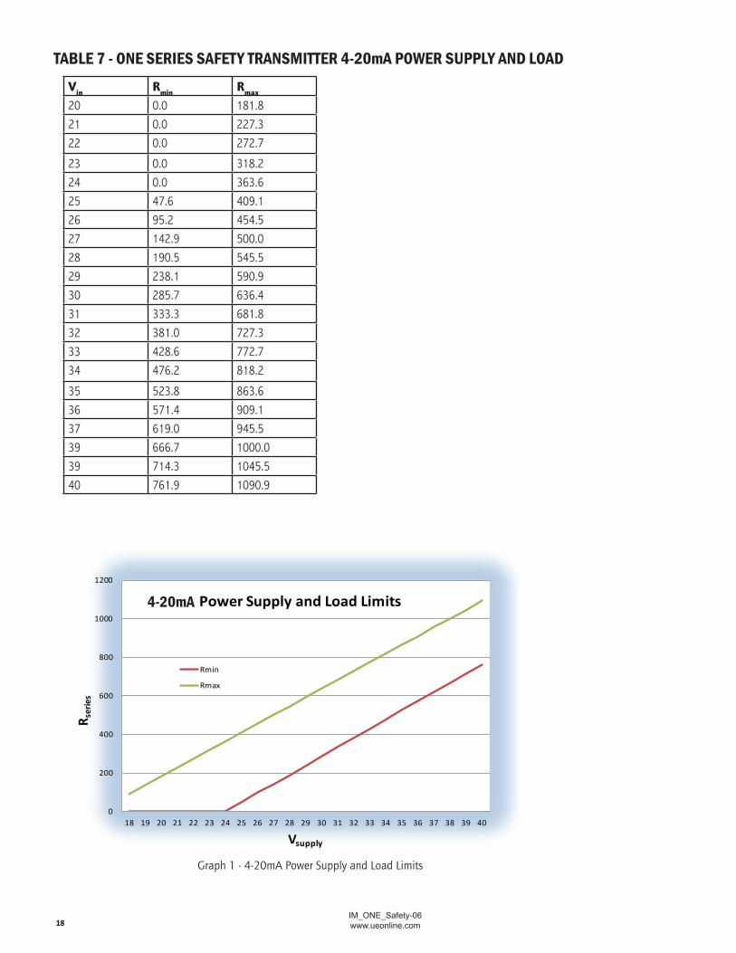
Power Supply and Load Limits
Rmin
Rmax
Vin Rmin Rmax
20 0.0 181.821 0.0 227.322 0.0 272.7
23 0.0 318.224 0.0 363.625 47.6 409.126 95.2 454.527 142.9 500.028 190.5 545.529 238.1 590.930 285.7 636.431 333.3 681.832 381.0 727.333 428.6 772.734 476.2 818.2
35 523.8 863.636 571.4 909.137 619.0 945.539 666.7 1000.039 714.3 1045.540 761.9 1090.9
TAbLE 7 - ONE SERIES SAfETY TRANSMITTER 4-20mA POWER SuPPLY ANd LOAd
Graph 1 - 4-20mA Power Supply and Load Limits
4-20mA

IM_ONE_Safety-06www.ueonline.com 19
Programming flow Chart
Process Display
1234
MAN RSET
Display to Scroll :
SP1 xxxx, DB1 xxxx, SP2 xxxx, DB2 xxxx
Display to Scroll : MAX xxxx, MIN xxxx
RSET DONE
BOTH
PASS WORD
8888
Set Blinking Digit
Increments Blinking Digit Sets Digit and moves to next
ENTER NEW
PWORD
PWORD Valid
8888
Set Blinking Digit
Increments Blinking Digit Sets Digit and moves to next
CONF PASSWORD 8888
BOTH
ABORT CHANGE
BOTH
If Latch Set No Latch Set
CLR MAX/MIN
CLR?
NO YES
SET UNITS
PSI BAR/mBAR °F KPa/MPa °C Kg/cm2 “wc
SW1
SP
8888
Set Blinking Digit
Increments Blinking Digit Sets Digit and moves to next
POS NEG Skip if range only POS
Set Point Outside Sensor Range
flash “Err”
DB
8888
Set Blinking Digit
Increments Blinking Digit Sets Digit and moves to next
Dead Band out of Range flash “Err”
Shortcut to Save
Changes
BOTH
OPENRISE
OPENFALL
WINDOW
SPH
DBH
SPL
DBL
Note: Enter Set Point High, Dead Band High, Set Point Low and Dead Band Low. Details of entry are similar to above.
Note: Bar/mBAR or KPa/MPa will depend on sensor range.
Invalid PWORD
BOTH Abort
NO RESET
OK
Flash Err
Abort
BDOOR PWORD Valid
SAVING
*
*
*
SAVING
One Series Safety Transmitter
LCH1 ON OFF
OFST
POS NEG
8888 Set Blinking Digit
Increments Blinking Digit Sets Digit and moves to next
SPAN
POS NEG
8888 Set Blinking Digit
Increments Blinking Digit Sets Digit and moves to next
Offset out of Range flash “Err”
SPAN out of Range flash “Err”
PLUG PORT
FILTER
Un-shaded = Display Toggles
Shaded = Display Scrolls
THIS DOCUMENT IS PROPRIETARY PROPERTY OF UNITED ELECTRIC CONTROLS
UNAUTHORIZED USE IS STRICTLY PROHIBITED
PLUG PORT
OFF 1MIN 1HR 24HR
If OFF is selected, pressing will return to menu
8888
Set Blinking Digit
Increments Blinking Digit Sets Digit and moves to next
Set Window
Setting > 10% of Range flash “Err”
SRO FAULT MONITOR
ON OFF
*
*
*
*
*
* Denotes shortcut to Save Changes when both buttons are pressed.
*
*
*
SAVE CHNG
NO
YES
Both saves changes
FILTER
4 MA SET
POS NEG
8888 Set Blinking Digit
Increments Blinking Digit Sets Digit and moves to next
20MA SET
POS NEG
8888 Set Blinking Digit
Increments Blinking Digit Sets Digit and moves to next
Out of Range flash “Err”
Out of Range flash “Err”
Both Discards changes
SAVING CHANGES
CHANGES DISCARDED
OFF 1/4S 1/2S 1Sec 2Sec

IM_ONE_Safety-06www.ueonline.com20
5.3”
5.7”
5.4”
6.1”
5.3 5.4
10.4”
8.0”
5.4”
5.3”
5.1”
5.4”
3.00”
3.63”
CLEARANCEHOLE FOR 1/4" BOLT
4 PLCS
5.3”
5.1”
5.4”
3/4” - 14 NPTCONDUIT PORTS
1/2” - 14 NPTSENSOR PORT
3/4” - 14 NPTCONDUIT PORTS
3/4” - 14 NPTCONDUIT PORTS
3/4” - 14 NPTCONDUIT PORTS
3/4” - 14 NPTCONDUIT PORTS
1/2” - 14 NPTSENSOR PORT
1/2” - 14 NPTSENSOR PORT
1”-20 NPTSENSOR PORT
1”-20 NPTSENSOR PORT
[111.92] mm
[76.2] mm
[133.35] mm
[12.7] mm
SURFACE MOUNTING KIT6361-704
[144.78] mm
[134.62] mm
[137.16] mm
[154.94] mm
[134.62] mm
[137.16] mm
[264.16] mm
[203.2] mm
[137.16] mm
[129.54] mm
[134.62] mm
[137.16] mm
[76.2] mm
[92.20] mm
[129.54] mm
[134.62] mm
[137.16] mm
[107.95] mm
[61.91] mm
[158.75] mm
[7.11] mm
[107.95] mm
[76.2] mm
[6.35] mm [8.73]
mm
All One Series ModelsdIMENSIONAL dRAWINGS

IM_ONE_Safety-06www.ueonline.com 21
4”, 6”, 10”[101.6, 152.4, 254] mm
(FIXED DIM.’S)
Ø0.250[6.35] mm 316 st/st
SHEATHWELD
1/2” NPT HEX FITTING300 SERIES st/st
22 AWG STRANDEDTEFLON INSULATION
4.50[114.3] mm
(FIXED DIM.)
EPOXY SEAL
0.94[23.87] mm
(FIXED DIM.)
4.50[114.3] mm
(FIXED DIM.)
EPOXY SEAL
1/2” NPTHEX FITTING300 SERIES st/st
22 AWG STRANDEDTEFLON INSULATION
1/2” NPTUNION300 SERIES st/st
316 st/stSHEATH
Ø0.250[6.35] mm
0.25[6.35] mmSPRINGLOAD
L DIM.(CUSTOMER SUPPLIED DIM.)
0.50[12.7] mm
NUN DIM.(CUSTOMER SUPPLIED DIM.)
L DIM.(CUSTOMER SUPPLIED DIM.)
2.5[63.5] mm
Ø0.250[6.35] mm
Ø0.125[3.18] mm 300 SERIES st/st
MINERAL INSULATED CABLEØ0.125, [3.18] mm (FOR DC UNITS)Ø0.188 [4.78] mm(FOR AC UNITS)
Ø0.250[6.35] mm 1/2” NPT COMPRESSION FITTING
300 SERIES st/st
26 AWG STRANDEDTEFLON INSULATION
4.50[114.3] mm
(FIXED DIM.)
EPOXY SEAL
2.00[50.8] mm
(FIXED DIM.)
1/2”-14 NPTPIPE NIPPLE300 SERIES st/st
0.50[12.7] mm
Temperature Sensors
SENSOR OPTIONS
Local Mount TL1 - TL3
differential Pressure
1/4”-18 NPT (MALE)BOTH ENDS3.0
[76.2mm]
1.06[26.9mm]
Gauge Pressure
1.06[26.9mm]
1/2”-14 NPT (FEMALE)
Pressure Sensors
Spring-Loaded Assembly with NuN Hardware
Remote
5.30”[134.6mm]
2.44”[61.9mm]
2.86”[72.6mm]
[221mm]
8.70”
DUAL SEAL ENCLOSURE1/8" NPT ANNUNCIATIONVENT CAN BE ROTATED UP TO90° IN EITHER DIRECTION
dual Seal with Gauge Pressure Sensor (Option M041)

IM_ONE_Safety-06www.ueonline.com22
UTILISATION ABUSIVE DE CE PRODUIT PEUT CAUSER UNE EXPLOSION ET DES BLESSURES. CES INSTRUCTIONS DOIVENT êTRE SOIGNEUSEMENT LUES ET COMPRISES AVANT L’ APPAREIL EST INSTALLé. VOIR L’INFORMATION SUR LA PLAQUE SIGNALéTIQUE DU PRODUIT POUR LES CERTIFICATIONS D’AGENCE SPéCIFIQUES APPLICABLES.
AVERTISSEMENT: RISQUE D’EXPLOSION - SUBSTITUTION DE L’ APPAREIL PEUT NUIRE à L’APTITUDE à L’UTILISATION DANS DES ENDROITS DAN-GEREUX.
AFIN DE RéPONDRE AUX EXIGENCES DE COMPATIBILITé éLECTROMAGNéTIQUE SPéCIFIéES DANS EN61000-6-2: IMMUNITé POUR LES ENVIRONNE-MENTS INDUSTRIELS, LE CâBLAGE EXTERNE DOIT êTRE EXéCUTé EN UTILISANT UN CâBLE AVEC UN BOUCLIER à LA TERRE OU LONGUEUR DE CâBLE à L’INTéRIEUR D’UN CONDUIT MéTALLIQUE.
AVERTISSEMENT: POUR LES ZONES EXPLOSIVES POUSSIéREUSES, TOUS LES DISPOSITIFS D’ENTRéE DE CâBLE DOIVENT êTRE CERTIFIéS DANS LE TYPE DE PROTECTION DE L’ ENCEINTE IGNIFUGE “D” AVEC UN INDICE DE PROTECTION IP66, ADAPTé AUX CONDITIONS D’UTILISATION ET CORRECTE-MENT INSTALLéS. SI LES CâBLES ET PRESSE-éTOUPES NE SONT PAS UTILISéS, UNE BOîTE D’ARRêT DOIT êTRE FOURNIE DANS LES 2 “(5 CM) DE
L’ENCEINTE. PLUS DE DéTAILS SONT FOURNIS à LA PAGE (15).
AVERTISSEMENT: RISQUE D’EXPLOSION - LES CONDUITS DOIVENT êTRE SCELLéS à L’INTéRIEUR DE 2 “(5 CM) DE L’ENCEINTE.
AVANT L’INSTALLATION, VéRIFIER LE MODèLE DE L’ APPAREIL SéLECTIONNé POUR LA COMPATIBILITé AVEC LE FLUIDE DU PROCéDé EN CONTACT AVEC LE CAPTEUR ET LES PARTIES MOUILLéES.
DANS TOUTES LES APPLICATIONS, SéCURISER L’ENCEINTE COMME DéTAILLé CI-DESSOUS. NE PAS INSTALLER PAR LA CONNEXION DE PROCESSUS SEULEMENT.
REMARQUE: POUR PRéVENIR LES EFFETS DES CYCLES THERMIQUES SUR L’ENCEINTE, LE TRANSMETTEUR ONE SéRIE DOIT êTRE PROTéGé DES RAYONS DU SOLEIL ET DE LA PLUIE DANS LES INSTALLATIONS DE PLEIN AIR à L’AIDE D’UN LINCEUL. L’AFFICHAGE NUMéRIQUE EST OPTIMISéE POUR L’AFFICHAGE DE LA POSITION 06:00.
POUR TOUS LES MODèLES DE PRESSION ET TEMPéRATURE NE PAS SERRER EN TOURNANT L’ ENCEINTE MAIS TOUJOURS UTILISER UNE Dé SUR L’ HEXAGONE DE LA CONNEXION PROCESSUS DE L’ APPAREIL , CAR CELA POURRAIT ENDOMMAGER LA CONNEXION ENTRE LE CAPTEUR ET L’ ENCEINTE.
INSTALLEZ LES UNITéS Où LES, VIBRATIONS ET LES FLUCTUATIONS DE TEMPéRATURE SONT MINIMES. ORIENTER L’ APPAREIL POUR EMPêCHER L’HUMIDITé DE PéNéTRER DANS L’ENCEINTE. NE PAS MONTER L’UNITé à DES TEMPéRATURES AMBIANTES DéPASSANT LES LIMITES PUBLIéES. CELA EST PARTICULIèREMENT IMPORTANT POUR LES UNITéS LOCALES DE TEMPéRATURE à MONTAGE LOCAL.
POUR LES MODèLES DE PRESSION DIFFéRENTIELLE (POUR LES PRESSIONS PARTICULIèREMENT FAIBLES), IL FAUT BIEN MONTER LE NIVEAU DU CAPTEUR AFIN DE MINIMISER LES DéCALAGES DE LECTURE DE PRESSION. LA COMMANDE DE DéCALAGE PEUT êTRE UTILISé à ZéRO L’AFFICHAGE, VOIR PAGE 14 POUR PLUS D’INFORMATIONS.
AVERTISSEMENT: NE JAMAIS INSéRER UN OBJET DANS L’ORIFICE DU CAPTEUR DE PRESSION. LES DOMMAGES à LA MEMBRANE DE CAPTEUR SE TRADUIRA, à AFFECTER LA PRéCISION DE MESURE DE PRESSION.
REMARQUE: LE PRODUIT PEUT êTRE MONTé DANS N’IMPORTE QUELLE POSITION. POUR LES PRESSIONS PARTICULIèREMENT FAIBLES, L’ORIENTATION DU CAPTEUR PEUT PRODUIRE UN ”OFFSET” SUR DANS L’AFFICHAGE EN RAISON DES EFFETS SUR LE REMPLISSAGE D’HUILE à L’ INTéRIEUR DU CAPTEUR. SI CELA SE PRODUIT, UTILISEZ LE RéGLAGE DE L’OFFSET POUR COMPENSER CET EFFET. VOIR PAGE 12 POUR PLUS D’INFORMATIONS SUR
LA COMMANDE DE DéCALAGE.
REMARQUE: UN KIT DE DéMONSTRATION EST DISPONIBLE EN OPTION – UTILISER LE NUMéRO DE PIèCE 6361-704. VOIR PAGE 20. SCELLER LE RACCORD DE PRESSION SUR LE SABORD DE PRESSION EN UTILISANT UN PRODUIT D’éTANCHéITé APPROPRIé, EN VEILLANT à CE QUE LES FILS DE CONTACT SONT PROPREMENT CONNECTéS. UTILISEZ UNE CLé SUR L’HEXAGONE DE CONNEXION DE PRESSION POUR SERRER. TESTER L’
IL Y A DES FUITES. POUR LE MODèLE DE LA PRESSION DIFFéRENTIELLE, LA PRESSION DU CôTé BAS (L) NE DOIT PAS DéPASSER LA PRESSION DU CôTé HAUT (H) CAR CELA POURRAIT ENDOMMAGER LE CAPTEUR POURRAIT ENTRAîNER.
POUR TOUS LES MODèLES DE TEMPéRATURE LOCAUX ET DISTANTS POUR LES MODèLES DE TEMPéRATURE LOCALES, MONTER L’APPAREIL EN UTILISANT LES TROUS DU MONTAGE SUR LE BOîTIER éLECTRONIQUE. MONTER LE PRODUIT DE SORTE QUE LE BOîTIER DU CAPTEUR NE SERA PAS ENDOMMAGé ET Où LA TEMPéRATURE MESURéE EST REPRéSENTATIVE
DE L’ENVIRONNEMENT ENVIRONNANT.
POUR LES CAPTEURS LOCALES à RESSORT: UTILISER UN PUITS THERMIQUE APPROPRIé, FAITES MATéRIAU RéSISTANT à LA CORROSION DU PROCES-SUS, 5 FILETS ENGAGéS MINIMUM, AVEC UN PRODUIT D’éTANCHéITé, EST NéCESSAIRE POUR MAINTENIR LE TYPE DE COFFRET 4X/IP66.
fRENCH WARNING TRANSLATIONS

IM_ONE_Safety-06www.ueonline.com 23
POUR LES MODèLES DE TEMPéRATURE DISTANTS: ITINéRAIRE DE FIL D’EXTENSION à éVITER TOUT CONTACT AVEC DES éLéMENTS SOUS TEN-SION OU à PROXIMITé DE SOURCES D’ INTERFéRENCES éLECTRIQUES. EVITER LES éTRANGLEMENTS OU FLEXIONS EXCESSIVES. SERREZ LE RACCORD D’EMBOUT, LE CAS éCHéANT.
POUR LA DéTECTION DE TEMPéRATURE D’ UNE SURFACE, SéCURISER LE CAPTURE SUR LA SURFACE EU UTILISANT DES MéTHODES QUI SONT APPROPRIé POUR L’ APPLICATION ET QUI GARANTIE UN MAXIMUM DE TRANSFERT DE CHALEUR ENTRE LA SURFACE ET LE CAPTEUR.
REMARQUE: POUR TOUS LES MODèLES DE TEMPéRATURE QUI SONT LOCALEMENT INSTALLé (MODèLES : C, H,R & L), L’ UTILISATION L’ UN PUITS THERMIQUE ES FORTEMENT RECOMMANDé POUR AIDER à L’ENTRETIEN , LES ESSAIS ET LA PRéSERVATION DE L’INTéGRITé DU SYSTèME . POUR LES PUITS THERMIQUES EXISTANTS AVEC 0,375 “DE DIAMèTRE, UN INSERT EST DISPONIBLE à COMMANDER EN UTILISANT LE CODE 62169-44.
L’ADAPTATEUR FOURNIT UN TRANSFERT DE CHALEUR PLUS RAPIDE EN ADAPTANT LE CAPTEUR DE TEMPéRATURE DE DIAMèTRE 0.250” à UN PLUS GRAND PUITS THERMIQUE DE DIAMèTRE 0.375”. COMPOSé DE TRANSFERT DE CHALEUR EST RECOMMANDéE DANS LE FOND DU PUITS THERMIQUE.
INSéREZ LE CAPTEUR (0,250 “ DE DIAMèTRE) DANS LE PUITS, VEILLER à CE QUE LE FOND EST COMPLèTEMENT IMMERGé DANS LE PROCéDé ( 2,5 “ MINIMUM ) AVEC LA POINTE DU PUITS THERMIQUE AU PLUS PRèS DU CENTRE DU TUYAU QUE POSSIBLE. VISSER LE MAMELON DE LA SONDE DANS LE PUITS THERMIQUE AVEC UN PRODUIT D’éTANCHéITé , EN PLAçANT UNE CLé SUR L’éCROU . AJUSTEZ LA POSITION DE L’éCRAN
DU TRANSMETTEUR ONE SERIES POUR UNE LECTURE FACILE. SERRER LE CONNECTEUR DE L’UNION POUR FIXER LE CAPTEUR DANS LE MUR.
POUR DE MEILLEURS RéSULTATS, LE CAPTEUR DE TEMPéRATURE DOIT êTRE EN CONTACT AVEC LA SURFACE OU LES MéDIAS MESURéS. UN COMPOSé DE TRANSFERT DE CHALEUR PEUT êTRE UTILISéE POUR AIDER à TRANSFéRER COMPLèTEMENT LA TEMPéRATURE DU FLUIDE AU CAPTEUR. LOCALISEZ LE CAPTEUR Où LA TEMPéRATURE EST LA PLUS REPRéSENTATIVE DE SYSTèME. LA PROFONDEUR D’INSERTION MINIMUM
EST DE 2-1/2 “. DESSINS DES CAPTEURS SONT PRéSENTéS à LA PAGE 21 .
SE RéFéRER à LA PAGE 13 DU BULLETIN POUR SAVOIR LES DIFFéRENTS TYPES DE RACCORDS ET ADAPTATEURS DISPONIBLES POUR FIXER LES CAPTEURS DE TEMPéRATURE.
AVERTISSEMENT: RISQUE D’EXPLOSION - POUR éVITER L’INFLAMMATION, COUPER L’ALIMENTATION AVANT DE RETIRER LE COUVERCLE DU BOî-TIER. MAINTENIR LE COUVERCLE FERMé PENDANT LE FONCTIONNEMENT. NE PAS DéCONNECTER L’éQUIPEMENT QUE LORSQUE L’ALIMENTATION EST COUPéE OU LORSQUE LA ZONE Où LE PRODUIT EST INSTALLé N’EST PAS UNE ZONE EXPLOSIVE.
AVERTISSEMENT: RISQUE D’EXPLOSION - NE PAS REMPLACEZ PAS L’INTERRUPTEUR DE SéCURITé QUE LORSQUE L’ALIMENTATION EST COUPéE ET QUAND LA ZONE EST CONNUE POUR êTRE NON DANGEREUX.
DANS TOUS LES APPAREILS, LE FIL DE TERRE DOIT êTRE BRANCHé PROPREMENT.
CâBLAGE SUR LE TERRAIN DOIT êTRE éVALUé 105 C MINIMUM . POUR UNE TEMPéRATURE AMBIANTE INFéRIEURE à -10°C, UTILISER LE CâBLAGE APPROPRIé.
MODèLES 2SLP EST ALIMENTé PAR LA BOUCLE ET DéLIVRE UN SIGNAL 4 -20MA . L’ALIMENTATION FOURNISSANT DE L’éNERGIE à LA BOUCLE DOIT êTRE DE CLASSE 2 OU à BASSE TENSION DE SéCURITé «SELV» . LA CHARGE MAXIMALE POUR SORTIE DE RELAIS DE SéCURITé ( SRO ) EST INDIQUé DANS LE TABLEAU à LA PAGE 18 ET COMPREND TOUTES LES SPéCIFICATIONS DE TEMPéRATURE. SURCHARGE DE LA SORTIE DE RELAIS
DE SéCURITé ( SRO ) PEUT PROVOQUER UNE PANNE . LE SRO NE DOIT PAS êTRE CONNECTé DIRECTEMENT à UNE SOURCE D’ALIMENTATION SANS RéSISTANCE EU SéRIE APPROPRIéE.
AVERTISSEMENT: DéBRANCHER TOUS LES CIRCUITS D’ALIMENTATION AVANT DE BRANCHER L’APPAREIL. LE CâBLAGE DOIT êTRE EFFECTUéE SELON LES CODES éLECTRIQUES NATIONAUX ET LOCAUX . TAILLES DE FILS RECOMMANDéES ET COUPLES DE SERRAGE POUR LE CâBLAGE SONT PRéSENTéS à LA PAGE 4.
RETIRER LE COUVERCLE DU BOîTIER DE RéGLAGE 8 TOURS DANS LE SENS ANTIHORAIRE. RETIREZ DéLICATEMENT LE MODULE D’AFFICHAGE PAR LE BORD EXTéRIEUR ET EN LE TIRANT TOUT EN FAISANT ATTENTION DE NE PAS FATIGUER LES FILS DE CONNEXION. LAISSER LE MODULE D’AFFICHAGE ATTACHé POUR LE FIL DE MIS-à-TERRE POUR ACCéDER à L’ENCEINTE DE BASE à TRAVERS L’OUVERTURE (S) DU CONDUIT DE L
ENCEINTE DE BASE. EFFECTUEZ LES CONNEXIONS COMME INDIQUé SUR LES SCHéMAS DE CâBLAGE, à LA PAGE 5 . DEUX MARQUES DE MIS-à-TERRE SONT CLAIREMENT MARQUéES SUR LE BOîTIER DE BASE INTERNE ET ADJACENTE à TB3 EXTERNE ET JUSTE AU-DESSUS DE L’OUVERTURE DE CON-DUIT SUR LE CôTé GAUCHE DE L’ENCEINTE.
POUR GARANTIR UNE BONNE FERMETURE DU COUVERCLE BOITIER , NE PAS ENLEVER LE LUBRIFIANT DE FIL. LES FILS DOIVENT êTRE VIDE DE SALETé ET D’AUTRES CONTAMINANTS .
NETTOYAGE DE L’éCRAN ET LA SURFACE DU CLAVIER DOIT êTRE EFFECTUé AVEC UN CHIFFON HUMIDE . NE PAS ESSAYER DE LAVER LE PRODUIT AVEC LE COUVERCLE RETIRé .

IM_ONE_Safety-06www.ueonline.com24
U N I T E D E L E C T R I C C O N T R O L S180 Dexter Ave. P.O. Box 9143, Watertown, MA 02472-9143 USA
617 926-1000 Fax 617 926-2568www.ueonline.com
ReCoMMeNDeD PRACtICeS AND WARNINGS
United Electric Controls Company recommends careful consideration of the follow-ing factors when specifying and installing UE pressure and temperature units. Before installing a unit, the Installation and Maintenance instructions provided with unit must be read and understood.
• To avoid damaging unit, proof pressure and maximum temperature limits stated in literature and on nameplates must never be exceeded, even by surges in the system. Operation of the unit up to maximum pressure or temperature is acceptable on a lim-ited basis (e.g., start-up, testing) but continuous operation must be restricted to the designated adjustable range. Excessive cycling at maximum pressure or temperature limits could reduce sensor life.
• A back-up unit is necessary for applications where damage to a primary unit could endanger life, limb or property. A high or low limit switch is necessary for applica-tions where a dangerous runaway condition could result.
• The adjustable range must be selected so that incorrect, inadvertent or malicious setting at any range point cannot result in an unsafe system condition.
• Install unit where shock, vibration and ambient temperature fluctuations will not damage unit or affect operation. When applicable, orient unit so that moisture does not enter the enclosure via the electrical connection. When appropriate, this entry point should be sealed to prevent moisture entry.
• Unit must not be altered or modified after shipment. Consult UE if modification is necessary.
• Monitor operation to observe warning signs of possible damage to unit, such as drift in set point or faulty display. Check unit immediately.
• Preventative maintenance and periodic testing is necessary for critical applications where damage could endanger property or personnel.
• Electrical ratings stated in literature and on nameplate must not be exceeded. Overload on a switch can cause damage, even on the first cycle. Wire unit accord-ing to local and national electrical codes, using wire size recommended in installa-tion sheet.
• Do not mount unit in ambient temp. Exceeding published limits.
LIMIteD WARRANtY
Seller warrants that the product hereby purchased is, upon delivery, free from defects in material and workmanship and that any such product which is found to be defec-tive in such workmanship or material will be repaired or replaced by Seller (Ex-works, Factory, Watertown, Massachusetts. INCOTERMS); provided, however, that this warranty applies only to equipment found to be so defective within a period of 24 months from the date of manufacture by the Seller (36 months for the Spectra 12 and One Series products; 18 months for Temperature Sensors). Seller shall not be obligated under this warranty for alleged defects which examination discloses are due to tampering, misuse, neglect, improper storage, and in any case where products are disassembled by anyone other than authorized Seller’s representatives. EXCEPT FOR THE LIMITED WARRANTY OF REPAIR AND REPLACEMENT STATED ABOVE, SELLER DISCLAIMS ALL WARRANTIES WHATSOEVER WITH RESPECT TO THE PRODUCT, INCLUDING ALL IMPLIED WARRANTIES OF MERCHANTABILITY OR FITNESS FOR ANY PARTICULAR PURPOSE.
LIMItAtIoN oF SeLLeR’S LIAbILItY
Seller’s liability to Buyer for any loss or claim, including liability incurred in connection with (i) breach of any warranty whatsoever, expressed or implied, (ii) a breach of contract, (iii) a negligent act or acts (or negligent failure to act) committed by Seller, or (iv) an act for which strict liability will be inputted to seller, is limited to the “limited warranty” of repair and/or replacement as so stated in our warranty of product. In no event shall the Seller be liable for any special, indirect, consequential or other damages of a like general nature, including, without limitation, loss of profits or production, or loss or expenses of any nature incurred by the buyer or any third party.
UE specifications subject to change without notice.
CP08113000