plt industrial & air master series model...
TRANSCRIPT

This manual contains important safety information and should be madeavailable to all personnel who operate and/or maintain this product.Carefully read this manual before attempting to operate or performmaintenance on this compressor.
Fill Out & Return Warranty Registration Card Located Inside
Manual No. 50334-101
February 2005 Edition
Parts ManualRecord of Change 101
PLPLPLPLPLTTTTT®®®®®
Industrial & Air Master Series Industrial & Air Master Series Industrial & Air Master Series Industrial & Air Master Series Industrial & Air Master Series
Model PLModel PLModel PLModel PLModel PLTTTTT-15-15-15-15-15

PLT-15 Industrial / Air Master Quincy Compressor
50334-101, February 2005 1 3501 Wismann Lane, Quincy IL - 62305-3116
TABLE OF CONTENTSSerial Number Identification ................................. 2
Ordering Replacement Parts ................................ 2
Crankcase Lubricant Capacity ............................. 2
Quin-Cip Lubricant ................................................ 2
Crankcase Group................................................... 3
Crankshaft Group .................................................. 4
Bearing Carrier Group ........................................... 5
Connecting Rod & Piston Groups .....................6-7
Cylinder & Head Groups ................................. 8-15
Manifold Group .................................................... 16
Control Piping Schematics ................................. 17
Pilot Valves .......................................................... 18
Pilot Valve Repair Kit .......................................... 18
Differential Setting Charts .................................. 18
Suction Valve Unloader Assemblies .................. 19
Decals ................................................................... 19
Typical Unit Repair Parts List ........................ 20-21
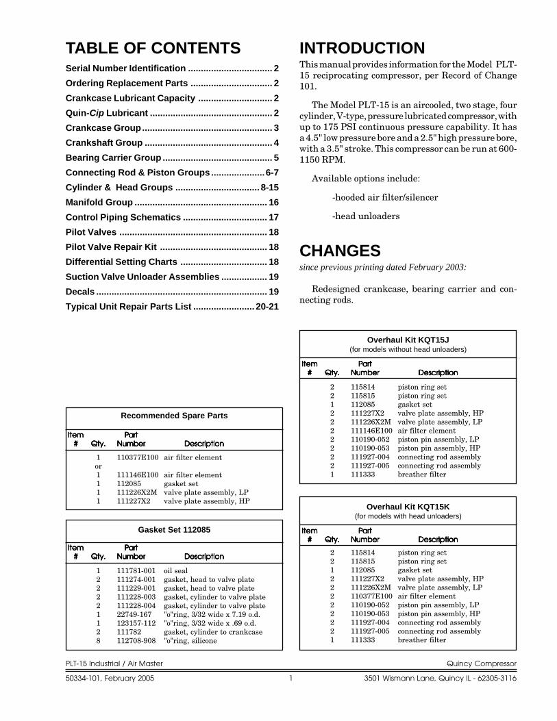
INTRODUCTIONThis manual provides information for the Model PLT-15 reciprocating compressor, per Record of Change101.
The Model PLT-15 is an aircooled, two stage, fourcylinder, V-type, pressure lubricated compressor, withup to 175 PSI continuous pressure capability. It hasa 4.5" low pressure bore and a 2.5" high pressure bore,with a 3.5" stroke. This compressor can be run at 600-1150 RPM.
Available options include:
-hooded air filter/silencer
-head unloaders
CHANGESsince previous printing dated February 2003:
Redesigned crankcase, bearing carrier and con-necting rods.
ItemItemItemItemItem PartPartPartPartPart##### Qty.Qty.Qty.Qty.Qty. NumberNumberNumberNumberNumber DescriptionDescriptionDescriptionDescriptionDescription
Overhaul Kit KQT15J(for models without head unloaders)
ItemItemItemItemItem PartPartPartPartPart##### Qty.Qty.Qty.Qty.Qty. NumberNumberNumberNumberNumber DescriptionDescriptionDescriptionDescriptionDescription
Overhaul Kit KQT15K(for models with head unloaders)
ItemItemItemItemItem PartPartPartPartPart##### Qty.Qty.Qty.Qty.Qty. NumberNumberNumberNumberNumber DescriptionDescriptionDescriptionDescriptionDescription
Gasket Set 112085
ItemItemItemItemItem PartPartPartPartPart##### Qty.Qty.Qty.Qty.Qty. NumberNumberNumberNumberNumber DescriptionDescriptionDescriptionDescriptionDescription
Recommended Spare Parts
1 110377E100 air filter elementor1 111146E100 air filter element1 112085 gasket set1 111226X2M valve plate assembly, LP1 111227X2 valve plate assembly, HP
2 115814 piston ring set2 115815 piston ring set1 112085 gasket set2 111227X2 valve plate assembly, HP2 111226X2M valve plate assembly, LP2 111146E100 air filter element2 110190-052 piston pin assembly, LP2 110190-053 piston pin assembly, HP2 111927-004 connecting rod assembly2 111927-005 connecting rod assembly1 111333 breather filter
2 115814 piston ring set2 115815 piston ring set1 112085 gasket set2 111227X2 valve plate assembly, HP2 111226X2M valve plate assembly, LP2 110377E100 air filter element2 110190-052 piston pin assembly, LP2 110190-053 piston pin assembly, HP2 111927-004 connecting rod assembly2 111927-005 connecting rod assembly1 111333 breather filter
1 111781-001 oil seal2 111274-001 gasket, head to valve plate2 111229-001 gasket, head to valve plate2 111228-003 gasket, cylinder to valve plate2 111228-004 gasket, cylinder to valve plate1 22749-167 "o"ring, 3/32 wide x 7.19 o.d.1 123157-112 "o"ring, 3/32 wide x .69 o.d.2 111782 gasket, cylinder to crankcase8 112708-908 "o"ring, silicone

PLT-15 Industrial / Air Master Quincy Compressor
50334-101, February 2005 2 3501 Wismann Lane, Quincy IL - 62305-3116
Package Part No. Description
Barrel 112541D032 55 gal., SAE 10WPail 112541P032 5 gal., SAE 10W
Gallon 112541G032 1 gal., SAE 10WGallon Case 112541X032 (4)-1 gal., SAE 10W
Quart 112541Q032 1 qt., SAE 10WQuart Case 112541C032 (12)-1 qt., SAE 10W
Barrel 112542D068 55 gal., SAE 20Pail 112542P068 5 gal., SAE 20
Gallon 112542G068 1 gal., SAE 20Gallon Case 112542X068 (4)-1 gal., SAE 20
Quart 112542Q068 1 qt., SAE 20Quart Case 112542C068 (12)-1 qt., SAE 20
Barrel 112543D100 55 gal., SAE 30Pail 112543P100 5 gal., SAE 30
Gallon 112543G100 1 gal., SAE 30Gallon Case 112543X100 (4)-1 gal., SAE 30
Quart 112543Q100 1 qt., SAE 30Quart Case 112543C100 (12)-1 qt., SAE 30
ORDERINGREPLACEMENT PARTSPrompt service can be rendered on repair parts ordersif the following information is given:
Item 1) the model number, record of change num-ber, & serial number.
Item 2) the exact part number needed. (Do notorder by item numbers.)
Item 3) the exact quantity needed.Item 4) the preferred type of transportation.
QUIN-CIP LUBRICANTRefer to the chart below to order Quin-Cip compres-sor lubricant from your local authorized Quincy dis-tributor.
CRANKCASE LUBRICANTCAPACITY
Model Capacity
PLT-15 33/4 qts.
SERIAL NUMBERIDENTIFICATIONThe unit serial number identification tag is located onthe air tank top plate. The basic compressor serialnumber decal is located on the side of the crankcaseopposite the oil fill side. Fill in the numbers from yourcompressor unit and basic compressor in the corre-sponding spaces provided here, and reference thispage when ordering replacement parts.
All replacement parts are to be ordered through anauthorized Quincy distributor. Insist on genuineQuincy parts only! Failure to do so may void war-ranty.
Unit Serial Number
Basic Serial Number
DANGER !
WARNING !
CAUTION !
CAUTION !Refer to the QT & PLT Series instruction manual for vitallubrication information.
Follow all safety precautions outlined in the QT & PLTSeries instruction manual.
Do not operate this compressor without a totally enclosedbelt guard or any other required safety equipment.
Air used for breathing or food processing must meet OSHA1910.134 or FDA 21 CFR 178.3570 regulations. Failure to doso may cause severe injury or death.

PLT-15 Industrial / Air Master Quincy Compressor
50334-101, February 2005 3 3501 Wismann Lane, Quincy IL - 62305-3116
CRANKCASE GROUP 111929-003CRANKCASE GROUP 111929-003CRANKCASE GROUP 111929-003CRANKCASE GROUP 111929-003CRANKCASE GROUP 111929-003

PLT-15 Industrial / Air Master Quincy Compressor
50334-101, February 2005 4 3501 Wismann Lane, Quincy IL - 62305-3116
CRANKSHAFT GROUP 111933-001CRANKSHAFT GROUP 111933-001CRANKSHAFT GROUP 111933-001CRANKSHAFT GROUP 111933-001CRANKSHAFT GROUP 111933-001

PLT-15 Industrial / Air Master Quincy Compressor
50334-101, February 2005 5 3501 Wismann Lane, Quincy IL - 62305-3116
BEARING CARRIER GROUP 110820-004BEARING CARRIER GROUP 110820-004BEARING CARRIER GROUP 110820-004BEARING CARRIER GROUP 110820-004BEARING CARRIER GROUP 110820-004

PLT-15 Industrial / Air Master Quincy Compressor
50334-101, February 2005 6 3501 Wismann Lane, Quincy IL - 62305-3116
CONNECTING ROD & PISTON GROUP 111925-004CONNECTING ROD & PISTON GROUP 111925-004CONNECTING ROD & PISTON GROUP 111925-004CONNECTING ROD & PISTON GROUP 111925-004CONNECTING ROD & PISTON GROUP 111925-004(low pressure)

PLT-15 Industrial / Air Master Quincy Compressor
50334-101, February 2005 7 3501 Wismann Lane, Quincy IL - 62305-3116
CONNECTING ROD & PISTON GROUP 111926-004CONNECTING ROD & PISTON GROUP 111926-004CONNECTING ROD & PISTON GROUP 111926-004CONNECTING ROD & PISTON GROUP 111926-004CONNECTING ROD & PISTON GROUP 111926-004(high pressure)

PLT-15 Industrial / Air Master Quincy Compressor
50334-101, February 2005 8 3501 Wismann Lane, Quincy IL - 62305-3116
HEAD GROUP 111935-1HEAD GROUP 111935-1HEAD GROUP 111935-1HEAD GROUP 111935-1HEAD GROUP 111935-1(*right bank / less head unloaders)
7
8
1917
7
15
9
9 20
11
12
3
5
12
6
18
4
13
9
22
24
21
1620
1023
23
23
ItemItemItemItemItem PartPartPartPartPart##### Qty.Qty.Qty.Qty.Qty. NumberNumberNumberNumberNumber DescriptionDescriptionDescriptionDescriptionDescription
2 112713M15 valve assembly kit, LP2 112714 valve assembly kit, HP2 111146E100 air filter element, (fits
111146F100 filter)
Head Kit KQT15B(for models without head unloader)

PLT-15 Industrial / Air Master Quincy Compressor
50334-101, February 2005 9 3501 Wismann Lane, Quincy IL - 62305-3116
HEAD GROUP 111935-1HEAD GROUP 111935-1HEAD GROUP 111935-1HEAD GROUP 111935-1HEAD GROUP 111935-1(*right bank / less head unloaders)
ItemItemItemItemItem PartPartPartPartPartNumberNumberNumberNumberNumber Qty.Qty.Qty.Qty.Qty. NumberNumberNumberNumberNumber DescriptionDescriptionDescriptionDescriptionDescription
Maintenance PartsMaintenance PartsMaintenance PartsMaintenance PartsMaintenance Parts
1 1 111115-5 cylinder head, high pressure2 1 111274-001 gasket, head to valve plate3 1 111227X2 valve plate assembly, high pressure4 1 112225-2 tube clamp5 1 111228-004 gasket, cylinder to valve plate6 1 110919-024 tube fitting, 90° male elbow, 3/4 tube x 3/4 npt7 8 123478-L25 hex. screw, 3/8-16 unc x 4.00, grade 5 (@ 30 ft.-lbs.)8 1 2392 pipe bushing, 1 npt x 3/4 npt9 9 110428N038 flatwasher, 3/810 1 111118-4 cylinder head, low pressure11 1 111229-001 gasket, head to valve plate12 1 111226X2M valve plate assembly, low pressure13 1 115037-L12 hex. screw with sealant, 3/8-16 unc x 1.00, grade 5 (@ 30 ft.-lbs.)14 1 111228-003 gasket, cylinder to valve plate15 1 23271 tube fitting, straight 3/4 tube x 3/4 npt16 1 2961-100 safety valve17 1 4816 pipe elbow, 3/4 npt18 1 112130 intercooler (N.S.S.; order Intercooler Replacement Kit)19 1 125936-009 pipe nipple, 3/4 npt x 1.8820 3 112709-006 plug, 3/4-16 unf ("o"ring included)21 1 112710-004 adapter, 3/4-16 unf x 1/4 npt ("o"ring included)22 1 111146F100 air filter
or22 1 111550S100 air filter/silencer, hooded
23 4 112708-908 "o"ring, silicone24 1 111146E100 air filter element, (fits 111146F100 filter)
or24 1 110377E100 air filter element, (fits 111550S100 filter/silencer)
1 112713M15 Valve Assembly Replacement Kit, LPincludes valve plate assembly & gaskets
1 112714 Valve Assembly Replacement Kit, HPincludes valve plate assembly & gaskets
1 112130K Intercooler Replacement Kitincludes intercooler and nut/sleeve fittings
*As viewed facing the compressor from the sheave side.N.S.S. = Not Sold Separate.@ Indicates torque value (dry threads).† Install with pipe sealant.Note: Tighten all bolts & capscrews in any bolt pattern, evenly bringing each bolt to torque in equal increments, while moving about
the bolt pattern. This is particularly true of connecting rod & head bolts.
†
†
††
†
PLT-15 Industrial / Air Master Quincy Compressor
50334-101, February 2005 10 3501 Wismann Lane, Quincy IL - 62305-3116
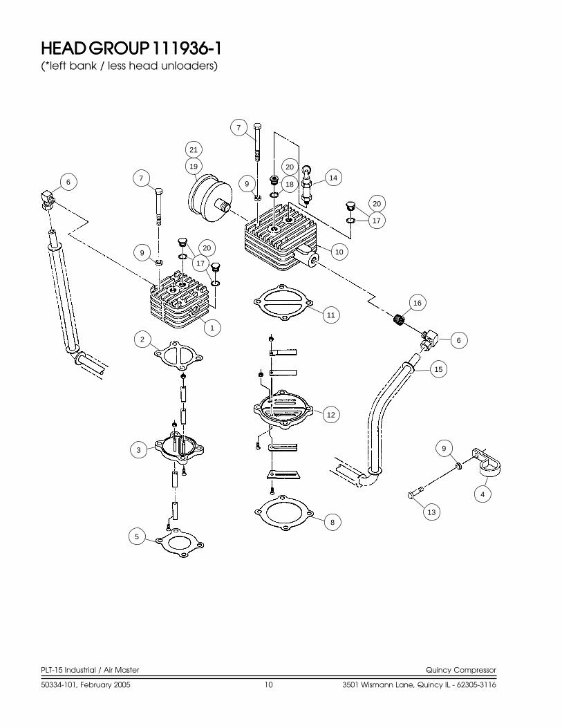
HEAD GROUP 111936-1HEAD GROUP 111936-1HEAD GROUP 111936-1HEAD GROUP 111936-1HEAD GROUP 111936-1(*left bank / less head unloaders)
15
6
11
12
16
10
17
14189
7
19
21
7
17
9
6
1
2
3
5
8
4
9
13
20
20
20

PLT-15 Industrial / Air Master Quincy Compressor
50334-101, February 2005 11 3501 Wismann Lane, Quincy IL - 62305-3116
HEAD GROUP 111936-1HEAD GROUP 111936-1HEAD GROUP 111936-1HEAD GROUP 111936-1HEAD GROUP 111936-1(*left bank / less head unloaders)
ItemItemItemItemItem PartPartPartPartPartNumberNumberNumberNumberNumber Qty.Qty.Qty.Qty.Qty. NumberNumberNumberNumberNumber DescriptionDescriptionDescriptionDescriptionDescription
Maintenance PartsMaintenance PartsMaintenance PartsMaintenance PartsMaintenance Parts
*As viewed facing the compressor from the sheave side.N.S.S. = Not Sold Separate.@ Indicates torque value (dry threads).† Install with pipe sealant.Note: Tighten all bolts & capscrews in any bolt pattern, evenly bringing each bolt to torque in equal increments, while moving about
the bolt pattern. This is particularly true of connecting rod & head bolts.
1 1 111115-5 cylinder head, high pressure2 1 111274-001 gasket, head to valve plate3 1 111227X2 valve plate assembly, high pressure4 1 112225-2 tube clamp5 1 111228-004 gasket, cylinder to valve plate6 2 110919-024 tube fitting, 90° male elbow, 3/4 tube x 3/4 npt7 8 123478-L25 hex. screw, 3/8-16 unc x 4.00, grade 5 (@ 30 ft.-lbs.)8 1 111228-003 gasket, cylinder to valve plate9 9 110428N038 flatwasher, 3/810 1 111118-4 cylinder head, low pressure11 1 111229-001 gasket, head to valve plate12 1 111226X2M valve plate assembly, low pressure13 1 115037-L12 hex. screw with sealant, 3/8-16 unc x 1.00, grade 5 (@ 30 ft.-lbs.)14 1 2961-100 safety valve15 1 112129 intercooler (N.S.S.; order Intercooler Replacement Kit)16 1 112825-002 pipe bushing, 1 npt x 3/4 npt17 3 112709-006 plug, 3/4-16 unf ("o"ring included)18 1 112710-004 adapter, 3/4-16 unf x 1/4 npt ("o"ring included)19 1 111146F100 air filter
or19 1 111550S100 air filter/silencer, hooded
20 4 112708-908 "o"ring, silicone21 1 111146E100 air filter element, (fits 111146F100 filter)
or21 1 110377E100 air filter element, (fits111550S100 filter/silencer)
1 112713M15 Valve Assembly Replacement Kit, LPincludes valve plate assembly & gaskets
1 112714 Valve Assembly Replacement Kit, HPincludes valve plate assembly & gaskets
1 112129K Intercooler Replacement Kitincludes intercooler and nut/sleeve fittings
†
†
††
†
†
PLT-15 Industrial / Air Master Quincy Compressor
50334-101, February 2005 12 3501 Wismann Lane, Quincy IL - 62305-3116
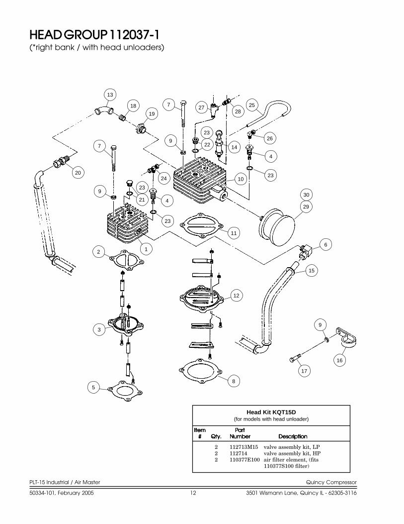
HEAD GROUP 112037-1HEAD GROUP 112037-1HEAD GROUP 112037-1HEAD GROUP 112037-1HEAD GROUP 112037-1(*right bank / with head unloaders)
7
9
23
12
7
9
2024
4
23
21
13
18
19
22
23
14
1023
4
26
2528
27
29
30
11
6
15
9
16
17
85
3
2 1
ItemItemItemItemItem PartPartPartPartPart##### Qty.Qty.Qty.Qty.Qty. NumberNumberNumberNumberNumber DescriptionDescriptionDescriptionDescriptionDescription
2 112713M15 valve assembly kit, LP2 112714 valve assembly kit, HP2 110377E100 air filter element, (fits
110377S100 filter)
Head Kit KQT15D(for models with head unloader)

PLT-15 Industrial / Air Master Quincy Compressor
50334-101, February 2005 13 3501 Wismann Lane, Quincy IL - 62305-3116
HEAD GROUP 112037-1HEAD GROUP 112037-1HEAD GROUP 112037-1HEAD GROUP 112037-1HEAD GROUP 112037-1(*right bank / with head unloaders)
ItemItemItemItemItem PartPartPartPartPartNumberNumberNumberNumberNumber Qty.Qty.Qty.Qty.Qty. NumberNumberNumberNumberNumber DescriptionDescriptionDescriptionDescriptionDescription
1 1 111115-5 cylinder head, high pressure2 1 111274-001 gasket, head to valve plate3 1 111227X2 valve plate assembly, high pressure4 2 111591X1 unloader5 1 111228-004 gasket, cylinder to valve plate6 1 110919-024 tube fitting, 90° male elbow, 3/4 tube x 3/4 npt7 8 123478-L25 hex. screw, 3/8-16 unc x 4.00, grade 5 (@ 30 ft.-lbs.)8 1 111228-003 gasket, cylinder to valve plate9 9 110428N038 flatwasher, 3/810 1 111118-4 cylinder head, low pressure11 1 111229-001 gasket, head to valve plate12 1 111226X2M valve plate assembly, low pressure13 1 4816 pipe elbow, 3/4 npt14 1 2961-100 safety valve15 1 112130 intercooler (N.S.S.; order Intercooler Replacement Kit)16 1 112225-2 tube clamp17 1 115037-L12 hex. screw with sealant, 3/8-16 unc x 1.00, grade 5 (@ 30 ft.-lbs.)18 1 125936-009 pipe nipple, 3/4 npt x 1.8819 1 2392 pipe bushing, 1 npt x 3/4 npt20 1 23271 tube fitting, straight 3/4 tube x 3/4 npt21 1 112709-006 plug, 3/4-16 unf ("o"ring included)22 1 112710-004 adapter, 3/4-16 unf x 1/4 npt ("o"ring included)23 2 112708-908 "o"ring, silicone24 1 124351-004 tube fitting, male branch tee, 1/4 tube x 1/4 npt25 1 110515-025 copper tube, 1/4 o.d.26 1 2708 tube fitting, 90° male elbow, 1/4 tube x 1/4 npt27 1 3003 pipe tee, 1/4 npt x 1/4 npt x 1/4 npt28 1 110594-005 tube fitting, male connector, 1/4 tube x 1/4 npt29 1 110377F100 air filter
or29 1 111550S100 air filter/silencer, hooded
30 1 110377E100 air filter element, (fits 110377F100 air filter and 111550S100 filter/silencer)1 112713M15 Valve Assembly Replacement Kit, LP
includes valve plate assembly & gaskets1 112714 Valve Assembly Replacement Kit, HP
includes valve plate assembly & gaskets1 112130K Intercooler Replacement Kit
includes intercooler and nut/sleeve fittings
Maintenance PartsMaintenance PartsMaintenance PartsMaintenance PartsMaintenance Parts
*As viewed facing the compressor from the sheave side.N.S.S. = Not Sold Separate.† Install with pipe sealant.@ Indicates torque value (dry threads)Note: Tighten all bolts & capscrews in any bolt pattern, evenly bringing each bolt to torque in equal increments, while moving about
the bolt pattern. This is particularly true of connecting rod & head bolts.
†
†
†
††††

PLT-15 Industrial / Air Master Quincy Compressor
50334-101, February 2005 14 3501 Wismann Lane, Quincy IL - 62305-3116
HEAD GROUP 112038-1HEAD GROUP 112038-1HEAD GROUP 112038-1HEAD GROUP 112038-1HEAD GROUP 112038-1(*left bank / with head unloaders)
10
20
76
9
26
27
20
18
21
4
9
7
20
19
22
1423
4
17
6
1120
1
15
12
9
13
168
2
3
5
2425

PLT-15 Industrial / Air Master Quincy Compressor
50334-101, February 2005 15 3501 Wismann Lane, Quincy IL - 62305-3116
HEAD GROUP 112038-1HEAD GROUP 112038-1HEAD GROUP 112038-1HEAD GROUP 112038-1HEAD GROUP 112038-1(*left bank / with head unloaders)
ItemItemItemItemItem PartPartPartPartPartNumberNumberNumberNumberNumber Qty.Qty.Qty.Qty.Qty. NumberNumberNumberNumberNumber DescriptionDescriptionDescriptionDescriptionDescription
1 1 111115-5 cylinder head, high pressure2 1 111274-001 gasket, head to valve plate3 1 111227X2 valve plate assembly, high pressure4 2 111591X1 unloader5 1 111228-004 gasket, cylinder to valve plate6 2 110919-024 tube fitting, 90° male elbow, 3/4 tube x 3/4 npt7 8 123478-L25 hex. screw, 3/8-16 unc x 4.00, grade 5 (@ 30 ft.-lbs.)8 1 111228-003 gasket, cylinder to valve plate9 9 110428N038 flatwasher, 3/810 1 111118-4 cylinder head, low pressure11 1 111229-001 gasket, head to valve plate12 1 111226X2M valve plate assembly, low pressure13 1 115037-L12 hex. screw with sealant, 3/8-16 unc x 1.00, grade 5 (@ 30 ft.-lbs.)14 1 2961-100 safety valve15 1 112129 intercooler (N.S.S.; order Intercooler Replacement Kit)16 1 112225-2 tube clamp17 1 112825-002 pipe bushing, 1 npt x 3/4 npt18 1 112709-006 plug, 3/4-16 unf ("o"ring included)19 1 112710-004 adapter, 3/4-16 unf x 1/4 npt ("o"ring included)20 2 112708-908 "o"ring, silicone21 1 124351-004 tube fitting, male branch tee, 1/4 tube x 1/4 npt22 1ft 110515-025 copper tube, 1/4 o.d.23 1 2708 tube fitting, 90° male elbow, 1/4 tube x 1/4 npt24 1 3003 pipe tee, 1/4 npt x 1/4 npt x 1/4 npt25 1 110594-005 tube fitting, 1/4 tube x 1/4 npt26 1 110377F100 air filter
or26 1 111550S100 air filter/silencer, hooded
27 1 110377E100 air filter element, (fits 110377F100 air filter and 111550S100 filter/silencer)1 112713M15 Valve Assembly Replacement Kit, LP
includes valve plate assembly & gaskets1 112714 Valve Assembly Replacement Kit, HP
includes valve plate assembly & gaskets1 112129K Intercooler Replacement Kit
includes intercooler and nut/sleeve fittings
Maintenance PartsMaintenance PartsMaintenance PartsMaintenance PartsMaintenance Parts
*As viewed facing the compressor from the sheave side.N.S.S. = Not Sold Separate.† Install with pipe sealant.@ Indicates torque value (dry threads)Note: Tighten all bolts & capscrews in any bolt pattern, evenly bringing each bolt to torque in equal increments, while moving about
the bolt pattern. This is particularly true of connecting rod & head bolts.
†
†
†
†††

PLT-15 Industrial / Air Master Quincy Compressor
50334-101, February 2005 16 3501 Wismann Lane, Quincy IL - 62305-3116
MANIFOLD GROUP 112257MANIFOLD GROUP 112257MANIFOLD GROUP 112257MANIFOLD GROUP 112257MANIFOLD GROUP 112257
ItemItemItemItemItem PartPartPartPartPartNumberNumberNumberNumberNumber Qty.Qty.Qty.Qty.Qty. NumberNumberNumberNumberNumber DescriptionDescriptionDescriptionDescriptionDescription
1 1 110919-024 tube fitting, 90° male elbow, 3/4 tube x 3/4 npt2 2ft 110515-075 copper tube, 3/4 OD3 1 23271 tube fitting, straight 3/4 tube x 3/4 npt4 1 122082 pipe tee, 1 npt x 3/4 npt x 3/4 npt5 1 124689-001 pipe nipple, 3/4 npt x close6 1 22238 pipe elbow, 45°, 1 npt7 1 6101 pipe nipple, 1 npt x close
6
7
4
5
3
21
†
†
† Install with pipe sealant.

PLT-15 Industrial / Air Master Quincy Compressor
50334-101, February 2005 17 3501 Wismann Lane, Quincy IL - 62305-3116
CONTROL PIPING SCHEMATICSCONTROL PIPING SCHEMATICSCONTROL PIPING SCHEMATICSCONTROL PIPING SCHEMATICSCONTROL PIPING SCHEMATICS
interstage
interstage

PLT-15 Industrial / Air Master Quincy Compressor
50334-101, February 2005 18 3501 Wismann Lane, Quincy IL - 62305-3116
PILOT VALVESPILOT VALVESPILOT VALVESPILOT VALVESPILOT VALVES
113321 series pilot valve(continuous run operation)
113320 series pilot valve(dual control operation)
Available 113321 Series Pilot Valves
Pilot ValvePilot ValvePilot ValvePilot ValvePilot Valve Pressure SettingPressure SettingPressure SettingPressure SettingPressure Setting
113321-090 80-90113321-100 90-100113321-110 100-110113321-125 110-125113321-140 130-140113321-150 135-150113321-165 150-165
Available 113320 Series Pilot Valves
Pilot ValvePilot ValvePilot ValvePilot ValvePilot Valve Pressure SettingPressure SettingPressure SettingPressure SettingPressure Setting
113320-095 75-95113320-115 100-115113320-140 125-140113320-165 150-165
WARNING !Not all pilots are for use with all compressor systems. Makesure that the pilot you order is set within the safe operatinglimits of your compressor. Failure to heed this warningcould result in an explosion.
Qty.Qty.Qty.Qty.Qty. Part DescriptionPart DescriptionPart DescriptionPart DescriptionPart Description
1 ball1 "o"ring1 piston1 diaphragm1 pilot spring1 piston spring1 toggle lever1 rivet1 muffler1 retaining ring
Can be used to repair 113320 & 113321 series pilot valvesPilot Valve Repair Kit 113320K
UnloadUnloadUnloadUnloadUnload Min. Dif.Min. Dif.Min. Dif.Min. Dif.Min. Dif. Max. Dif.Max. Dif.Max. Dif.Max. Dif.Max. Dif.(PSI)(PSI)(PSI)(PSI)(PSI) (PSI)(PSI)(PSI)(PSI)(PSI) (PSI)(PSI)(PSI)(PSI)(PSI)
40 2 560 3 10
100 4 20150 5 30175 5 45
Applies to 113320 & 113321 series pilot valves
Differential Setting Chart

PLT-15 Industrial / Air Master Quincy Compressor
50334-101, February 2005 19 3501 Wismann Lane, Quincy IL - 62305-3116
WARNING !
Interstage Blowdown ValveInterstage Blowdown ValveInterstage Blowdown ValveInterstage Blowdown ValveInterstage Blowdown Valve113320 & 113321 series pilot valves feature aninterstage blowdown valve which bleeds interstagepressure back to atmosphere when the compressor isrunning unloaded. This reduces the unloaded horse-power.
InstallationInstallationInstallationInstallationInstallationThe pilot valve is mounted directly into the air tank.Compressors in the field, not equipped with thesecontrols, can be converted. Consult your local Quincydistributor for assistance with conversion procedures.
ServiceServiceServiceServiceServiceIf a change in pilot valve operation is detected, re-move the pilot valve from the air tank and check thescreen in the inlet of the pilot valve for obstructions.Clean the screen if necessary.
AdjustmentAdjustmentAdjustmentAdjustmentAdjustmentThe unloading pressure is adjustable and is regulatedby turning the unload adjustment hex nut (refer topilot valve illustrations). Turn the hex nut clockwiseto increase and counterclockwise to decrease theunloading pressure.
The differential (difference between unloadingand loading pressure) is set by turning the differen-tial adjustment hex nut (refer to pilot valve illustra-tions). Increase the differential pressure by turningthe hex nut clockwise - decrease by turning counter-clockwise. Make all adjustments in small increments.Tighten the locknuts after adjustment.
SUCTION VALVEUNLOADER ASSEMBLIESDescriptionDescriptionDescriptionDescriptionDescriptionThe Quincy suction valve unloader assembly consistsof unloading assemblies on the suction valves, havinga plunger to contact the suction valve reed and anunloader pilot valve (113320 or 113321 series) toautomatically regulate the passing of air tank pres-sure to the unloading arrangement.
Continuous Run OperationContinuous Run OperationContinuous Run OperationContinuous Run OperationContinuous Run OperationSuction valve unloader assemblies are recommendedfor use on Quincy compressors where the compressoris to run continuously and a constant pressure is to bemaintained. The purpose is to automatically unseatthe suction valve of the compressor when the airsupply is greater than the demand.
Unloading occurs when air tank pressure is suffi-cient to overcome pilot valve spring pressure. Thecheck ball is then unseated, allowing air tank pres-sure to pass to the unloader assemblies. The compres-sor will run unloaded until the air tank pressuredrops to a predetermined level. At this time, theaction of the ball is reversed, shutting off air tankpressure to the unloader assemblies and venting theunloader to atmosphere. This allows the compressorto load. The drive, either electric motor or engine,runs continuously and must be started and stoppedmanually. 113321 series pilot valves feature a togglelever which can be flipped to provide manual unload-ing.
Dual Control OperationDual Control OperationDual Control OperationDual Control OperationDual Control OperationDual control operation is designed to provide a
choice between "start/stop" or "continuous run" op-eration. The 113320 series pilot valve can be set for"start/stop" operation by turning the knurled knob atthe end of the pilot valve (refer to illustration for113320 series pilot valve) clockwise until it stops.Under these circumstances, a pressure switch is re-quired to stop the motor. Failure to use a pressureswitch, with the pilot valve locked out, will result inunsafe conditions.
A pressure switch must be incorporated whenever 113320series pilot valve is employed as part of the control system.
The compressor will operate in the continuous runmode if the knurled knob is turned counterclockwiseuntil it stops.
ItemItemItemItemItem PartPartPartPartPart##### Qty.Qty.Qty.Qty.Qty. NumberNumberNumberNumberNumber DescriptionDescriptionDescriptionDescriptionDescription
Decals
1 1 110831 serial number & nameplate2 1 127889-A decal, CAUTION!, MANUAL3 1 127889-B decal, DANGER!,"Air from this...."
DECALS

PLT-15 Industrial / Air Master Quincy Compressor
50334-101, February 2005 20 3501 Wismann Lane, Quincy IL - 62305-3116
TYPICAL UNIT REPAIR PARTS LISTTYPICAL UNIT REPAIR PARTS LISTTYPICAL UNIT REPAIR PARTS LISTTYPICAL UNIT REPAIR PARTS LISTTYPICAL UNIT REPAIR PARTS LIST
(PLT-15 simplex - horizontal tank - electric motor)
PartPartPartPartPart PartPartPartPartPart PartPartPartPartPartQtyQtyQtyQtyQty NumberNumberNumberNumberNumber NumberNumberNumberNumberNumber NumberNumberNumberNumberNumber DescriptionDescriptionDescriptionDescriptionDescription
80 gal. 120 gal. 200 gal.1 113269-200 113272-200 113273-200 tank1 113277 n/a 113282-001 top plate1 2713 111136-050 111136-050 tank drain valve1 111136-100 111136-100 111136-100 service valve1 110514-300 110514-300 110514-200 pressure gauge1 110512-005 110512-005 110512-005 pressure switch, 135-175 PSI1 110513-200 110513-200 110513-200 pressure relief valve, 200 PSI (in tank)1 2961-215 2961-215 2961-215 pressure relief valve, 215 PSI (in discharge line)1 114800-100 114800-100 114800-100 check valve1 114559-003 114559-003 114559-003 discharge tube2 111265-100 111265-100 111265-100 ferrule/sleeve
10 h.p. 15 h.p.2 110258B094 110258B098 drive belt1 8458 116378 motor pulley1 5380 8936 bushing1 112432K003 112432K003 belt guard assembly
200v, 3Ø 230/460v, 3Ø1 40656 4014 10 h.p. motor (ODP)1 40657 127466L042 15 h.p. motor (ODP)
PartPartPartPartPart PartPartPartPartPart PartPartPartPartPartQtyQtyQtyQtyQty NumberNumberNumberNumberNumber NumberNumberNumberNumberNumber NumberNumberNumberNumberNumber DescriptionDescriptionDescriptionDescriptionDescription
200 gal. 240 gal.1 113468-200 113470-200 tank2 113282-001 113282-001 top plate1 111136-050 111136-050 tank drain valve1 111136-075 111136-100 service valve1 110514-300 110514-300 pressure gauge2 110512-005 110512-005 pressure switch, 135-175 PSI1 110513-200 110513-200 pressure relief valve, 200 PSI (in tank)2 2961-215 2961-215 pressure relief valve, 215 PSI (in discharge line)2 114800-100 114800-100 check valve2 114559-003 114559-003 discharge tube4 111265-100 111265-100 ferrule/sleeve
10 h.p. 15 h.p.4 110258B094 110258B098 drive belt2 8458 116378 motor pulley2 5380 8936 bushing2 112432K003 112432K003 belt guard assembly
200v, 3Ø 230/460v, 3Ø2 40656 4014 10 h.p. motor (ODP)2 40657 127466L042 15 h.p. motor (ODP)
(PLT-15 duplex - horizontal tank - electric motor)
Part numbers shown in italics apply to tank mounted units and base mounted units.
The parts listed here are for standard PLT-15 units and may or may not be applicable to specially built units. Check with your localauthorized Quincy distributor for parts that can be used for custom built units. Make sure the components you order are rated within thesafe operating limits of your system. If you are doubtful about which components to order, contact your local Quincy distributor.

PLT-15 Industrial / Air Master Quincy Compressor
50334-101, February 2005 21 3501 Wismann Lane, Quincy IL - 62305-3116
TYPICAL UNIT REPAIR PARTS LISTTYPICAL UNIT REPAIR PARTS LISTTYPICAL UNIT REPAIR PARTS LISTTYPICAL UNIT REPAIR PARTS LISTTYPICAL UNIT REPAIR PARTS LISTThe parts listed here are for standard PLT-15 units and may or may not be applicable to custom built units. Check with your localauthorized Quincy distributor for parts that can be used for custom built units. Make sure the components you order are rated within thesafe operating limits of your system. If you are doubtful about which components to order, contact your local Quincy distributor.
(PLT-15 gasoline engine driven)
PartPartPartPartPart PartPartPartPartPart PartPartPartPartPartQtyQtyQtyQtyQty NumberNumberNumberNumberNumber NumberNumberNumberNumberNumber NumberNumberNumberNumberNumber DescriptionDescriptionDescriptionDescriptionDescription
base unit tank unit1 113716-200 tank, 200 psi1 113717 113717 top plate1 111136-025 tank drain valve1 111136-075 ball valve1 110514-300 pressure gauge1 110513-200 pressure relief valve, 200 PSI (in tank)2 110357B090 110357B090 drive belt1 110662 110662 engine pulley1 8924 8924 engine pulley bushing1 112432-003 112432-003 belt guard assembly1 113143-004 113143-004 throttle control1 113720-001 113720 Kohler engine group, 18 h.p. (includes exhaust system & throttle control)
2 ft. 110515-100 discharge tube (1" copper tube to be formed by customer)2 111265-100 ferrule / sleeve1 114800-100 114800-100 check valve1 2961-215 2961-215 pressure relief valve, 215 PSI (discharge line)1 112316 112316 fuel tank group, 6 gal. (incl. fuel tank & 6 ft. of hose)1 113708-175 113708-175 pilot, 165-175 PSI
!
! Pre-formed discharge tubes are available. Contact factory with model & tank size information.

PLT-15 Industrial / Air Master Quincy Compressor
50334-101, February 2005 22 3501 Wismann Lane, Quincy IL - 62305-3116
QUINCY COMPRESSOR
STANDARD TERMS AND CONDITIONSLEGAL EFFECT: Except as expressly otherwise agreed to in writing by an
authorized representative of Seller, the following terms and conditions shallapply to and form a part of this order and any additional and/or different termsof Buyer’s purchase order or other form of acceptance are rejected in advanceand shall not become a part of this order.
The rights of Buyer hereunder shall be neither assignable nor transferableexcept with the written consent of Seller.
This order may not be canceled or altered except with the written consentof Seller and upon terms which will indemnify Seller against all lossoccasioned thereby. All additional costs incurred by Seller due to changes indesign or specifications, modification of this order or revision of product mustbe paid for by Buyer.
In addition to the rights and remedies conferred upon Seller by this order,Seller shall have all rights and remedies conferred at law and in equity andshall not be required to proceed with the performance of this order if Buyeris in default in the performance of such order or of any other contract or orderwith seller.
TERMS OF PAYMENT: Unless otherwise specified in the order acknowl-edgment, the terms of payment shall be 1% 15, net forty-five (45) days aftershipment. These terms shall apply to partial as well as complete shipments.If any proceeding be initiated by or against Buyer under any bankruptcy orinsolvency law, or in the judgment of Seller the financial condition of Buyer,at the time the equipment is ready for shipment, does not justify the terms ofpayment specified, Seller reserves the right to require full payment in cashprior to making shipment. If such payment is not received within fifteen (15)days after notification of readiness for shipment, Seller may cancel the orderas to any unshipped item and require payment of its reasonable cancellationcharges.
If Buyer delays shipment, payments based on date of shipment shallbecome due as of the date when ready for shipment. If Buyer delayscompletion of manufacture, Seller may elect to require payment according topercentage of completion. Equipment held for Buyer shall be at Buyer’s riskand storage charges may be applied at the discretion of Seller.
Accounts past due shall bare interest at the highest rate lawful to contractfor but if there is no limit set by law, such interest shall be eighteen percent(18%). Buyer shall pay all cost and expenses, including reasonable attorney’sfees, incurred in collecting the same, and no claim, except claims withinSeller’s warranty of material or workmanship, as stated below, will berecognized unless delivered in writing to Seller within thirty (30) days afterdate of shipment.
TAXES: All prices exclude present and future sales, use, occupation,license, excise, and other taxes in respect of manufacture, sales or delivery,all of which shall be paid by Buyer unless included in the purchase price atthe proper rate or a proper exemption certificate is furnished.
ACCEPTANCE: All offers to purchase, quotations and contracts of salesare subject to final acceptance by an authorized representative at Seller’splant.
DELIVERY: Except as otherwise specified in this quotation, delivery willbe F. O. B. point of shipment. In the absence of exact shipping instruction,Seller will use its discretion regarding best means of insured shipment. Noliability will be accepted by Seller for so doing. All transportation charges areat Buyer’s expense. Time of delivery is an estimate only and is based uponthe receipt of all information and necessary approvals. The shipping scheduleshall not be construed to limit seller in making commitments for materials orin fabricating articles under this order in accordance with Seller’s normal andreasonable production schedules.
Seller shall in no event be liable for delays caused by fires, acts of God,strikes, labor difficulties, acts of governmental or military authorities, delaysin transportation or procuring materials, or causes of any kind beyond Seller’scontrol. No provision for liquidated damages for any cause shall apply underthis order. Buyer shall accept delivery within thirty (30) days after receipt ofnotification of readiness for shipment. Claims for shortages will be deemedto have been waived if not made in writing with ten (10) days after the receiptof the material in respect of which any such shortage is claimed. Seller is not
responsible for loss or damage in transit after having received “In GoodOrder” receipt from the carrier. All claims for loss or damage in transit shouldbe made to the carrier.
TITLE & LIEN RIGHTS: The equipment shall remain personal property,regardless of how affixed to any realty or structure. Until the price (includingany notes given therefore) of the equipment has been fully paid in cash, Sellershall, in the event of Buyer’s default, have the right to repossess suchequipment.
PATENT INFRINGMENT: If properly notified and given an opportunityto do so with friendly assistance, Seller will defend Buyer and the ultimateuser of the equipment from any actual or alleged infringement of anypublished United States patent by the equipment or any part thereof furnishedpursuant hereto (other than parts of special design, construction, or manufac-ture specified by and originating with Buyer), and will pay all damages andcosts awarded by competent court in any suit thus defended or of which it mayhave had notice and opportunity to defend as aforesaid.
STANDARD WARRANTY: Seller warrants that products of its ownmanufacture will be free from defects in workmanship and materials undernormal use and service for the period specified in the product instructionmanual. Warranty for service parts will be Ninety (90) days from date offactory shipment. Electric Motors, gasoline and diesel engines, electricalapparatus and all other accessories, components and parts not manufacturedby Seller are warranted only to the extent of the original manufacturer’swarranty.
Notice of the alleged defect must be given to the Seller, in writing with allidentifying details including serial number, type of equipment and date ofpurchase within thirty (30) days of the discovery of the same during thewarranty period.
Seller’s sole obligation on this warranty shall be, at its option, to repair orreplace or refund the purchase price of any product or part thereof whichproves to be defective. If requested by Seller, such product or part thereofmust be promptly returned to seller, freight prepaid, for inspection.
Seller warrants repaired or replaced parts of its own manufacture againstdefects in materials and workmanship under normal use and service for ninety(90) days or for the remainder of the warranty on the product being repaired.
This warranty shall not apply and Seller shall not be responsible or liablefor:
(a) Consequential, collateral or special losses or damages;
(b) Equipment conditions caused by fair wear and tear, abnormalconditions of use, accident, neglect or misuse of equipment, improper storageor damage resulting during shipping;
(c) Deviation from operating instructions, specifications or otherspecial terms of sale;
(d) Labor charges, loss or damage resulting from improper operation,maintenance or repairs made by person(s) other than Seller or Seller’sauthorized service station.
In no event shall Seller be liable for any claims whether arising from breachof contract or warranty or claims of negligence or negligent manufacture inexcess of the purchase price.
THIS WARRANTY IS THE SOLE WARRANTY OF SELLERS ANDANY OTHER WARRANTIES, WHETHER EXPRESS OR IMPLIED INLAW OR IMPLIED IN FACT, INCLUDING ANY WARRANTIES OFMERCHANTABILITY AND FITNESS FOR PARTICULAR USE AREHEREBY SPECIFICALLY EXCLUDED.
LIABILITY LIMITATIONS: Under no circumstances shall the Seller haveany liability for liquidated damages or for collateral, consequential or specialdamages or for loss of profits, or for actual losses or for loss of production orprogress of construction, whether resulting from delays in delivery or perfor-mance, breach of warranty, negligent manufacture or otherwise.
ENVIROMENTAL AND OSHA REQUIREMENTS: At the time of ship-ment of the equipment from the factory, Quincy Compressor / Ortman FluidPower will comply with the various Federal, State and local laws andregulations concerning occupational health and safety and pollution. How-ever, in the installation and operation of the equipment and other matters overwhich the seller has no control, the Seller assumes no responsibility forcompliance with those laws and regulations, whether by the way of indem-nity, warranty or otherwise.
June 30, 2003


ReciprReciprReciprReciprReciprocating / Systems:ocating / Systems:ocating / Systems:ocating / Systems:ocating / Systems: 217.222.7700
Air MasterAir MasterAir MasterAir MasterAir Master 217.277.0270
E-mail:E-mail:E-mail:E-mail:E-mail: [email protected]
WWWWWebsite:ebsite:ebsite:ebsite:ebsite: quincycompressor.com
quincyairmaster.com
© 2006 Quincy Compressor, an EnPro Industries company
All Rights Reserved. Litho in U.S.A.