plugs and profiles - george e king petroleum engineering ... · pdf fileplugs and profiles...
TRANSCRIPT

Plugs and Profiles
• Types
• Running
• Pulling
• Problems
Plugs are set for many reasons – but mostly for isolation of pressures.
Not all plugs are a permanent seal. Sand plugs, cement plugs and inflatables have special requirements.
3/14/2009 1George E. King Engineering
GEKEngineering.com

A typical plug showing seals, equalization ports and locking keys
3/14/2009 2George E. King Engineering
GEKEngineering.com

Non-Selective Nipples
Lock recess
Seal bore
No-go
A single non selective nipple is usually all that is run in a well and it is usually at the bottom.
3/14/2009 3George E. King Engineering
GEKEngineering.com

Selective Nipples
Lock recess
Seal area
Landing recess
Essentially full opening (about 0.1” less ID than pipe)
Allows running multiple profiles, each with same ID. Set is determined by running tool.
3/14/2009 4George E. King Engineering
GEKEngineering.com

3/14/2009 5George E. King Engineering
GEKEngineering.com

S Profile with plug installed. Showing locking section.
3/14/2009 6George E. King Engineering
GEKEngineering.com

S profile, seal assembly in the polish bore section
3/14/2009 7George E. King Engineering
GEKEngineering.com

S Profile – locking section
3/14/2009 8George E. King Engineering
GEKEngineering.com

3/14/2009 9George E. King Engineering
GEKEngineering.com

XN (left) and X profile (right). X profiles allow several to be run in series in the string (same size plug passes through each). Only one XN can be run (on the bottom).
3/14/2009 10George E. King Engineering
GEKEngineering.com

3/14/2009 11George E. King Engineering
GEKEngineering.com

3/14/2009 12George E. King Engineering
GEKEngineering.com

A ported profile and plug.
3/14/2009 13George E. King Engineering
GEKEngineering.com

Other Profiles
• Flow Couplings –– heavy wall tube, 1 to 6 ft long (0.3 to 2m), made
of high allow steel. – same ID as tubing but similar OD to coupling– protection from internal erosion and corrosion– Used where excessive turbulence is expected
• above and below some profiles• above crossovers• above bottom hole chokes
3/14/2009 14George E. King Engineering
GEKEngineering.com

Other Profiles
• Blast Joints –– Similar to flow couplings but designed to resist
exterior erosion and abrasion
– 3 to 20+ ft long (1 to 6+m)
– Used opposite perforations
– Used opposite annular proppant entry point
– Used in straddled intervals in dual completions
3/14/2009 15George E. King Engineering
GEKEngineering.com

Other Equipment
• Downhole Chokes– a set diameter restriction in the tubing that takes
some pressure drop downhole. • Used for up-hole hydrate prevention by taking some
expansion of gas (cooling) in the downhole area where insitu temperatures are higher.
• Used for production or injection limiting.
• Stabilize bottom hole pressures
3/14/2009 16George E. King Engineering
GEKEngineering.com

Downhole Choke
3/14/2009 17George E. King Engineering
GEKEngineering.com

Sliding Sleeves
closed
open
3/14/2009 18George E. King Engineering
GEKEngineering.com

Other Equipment
• Downhole Regulators– a variable diameter restriction in the tubing that
takes some pressure drop downhole according to the rate of flow.
• Used for up-hole hydrate prevention by taking some expansion of gas (cooling) in the downhole area where insitu temperatures are higher.
• Used for production or injection limiting.
• Stabilize bottom hole pressures at variable rates
3/14/2009 19George E. King Engineering
GEKEngineering.com

3/14/2009 20George E. King Engineering
GEKEngineering.com

Latch recess
“Pocket”
Port to annulus
Access to tubular Flow Path
Indexing Groove
Side pocket Mandrel for gas lift or chemical injection
3/14/2009 21George E. King Engineering
GEKEngineering.com

Seal Swelling Problems
• Gas permeation
• Solvent swelling of seals
3/14/2009 22George E. King Engineering
GEKEngineering.com

Swollen seals on a plug retrieved from 10,000 ft
Left – one minute after pulling from the well, Right – after sixty minutes
Seal swell happens mostly on the trip up the hole as pressure is released and gas tries to leak out of the seal. It is not usually a cause of sticking.
3/14/2009 23George E. King Engineering
GEKEngineering.com

Avoiding Profile Debris Problems
• Cementing - protect the nipple profile with a sleeve similar to an insert sleeve used in a downhole safety valve
3/14/2009 24George E. King Engineering
GEKEngineering.com

When Sand Fill is Present
• “There was some sand present in the well, which gave us difficulties to run in hole at 63 deg dev. The problem was overcome by flowing the well slightly while running in, thus creating turbulences around the tool to flush away "sand dunes" building up in front of the tool.” – Charlie Michel, BP
North Sea operations comments – However, watch the potential for sticking with the sand washed above the tool.
3/14/2009 25George E. King Engineering
GEKEngineering.com

The extension on the bottom of the plug (left side of picture) allows debris to fall through and away from the internal fishing neck.
3/14/2009 26George E. King Engineering
GEKEngineering.com

Equalizing Prong with marks to differential contact on steel or sand.
3/14/2009 27George E. King Engineering
GEKEngineering.com

Specialty plugs are available that will set in almost any type of tubular, regardless of the presence or absence of a profile, but a seal always depends on the integrity of the tubing in which the plug is set.
Schlumberger3/14/2009 28
George E. King Engineering GEKEngineering.com

Slickplug - The Retrievable Bridge Plug
Available from 2 3/8” to 7”nominal sizes
Pressure ratings in excess of 5,000 psi working
Temperature ratings up to 350°F
Barrier for Tree change - outs
Contingency tubing plugging
Zonal isolation tool
Location of flow control devices
Upper Slips
Pack-offElement
Lower Slips
Bow Spring
EqualisingAssembly
PumpopenPlug
Weatherford3/14/2009 29George E. King Engineering
GEKEngineering.com

WRP Wireline Set Retrievable Bridge Plug
Retrievable Bridge Plugs
Features:• Run and retrieved under pressure• Straight pull to release• Can be retrieved on coiled tubing• Pressure differential is equalized with washover
retrieving tool• Electric wireline setting with industry standard setting
tools
Used for isolating zones during fracturing, acidizing or cementing operations or during wellhead
removal
Weatherford3/14/2009 30
George E. King Engineering GEKEngineering.com

Laying Sand Plugs
• Shut-in well for several hours to prevent crossflow disruption of plug.
• Don’t bury the BHA with dumped sand• Tag frequently to avoid over-fill• Use a gell spacer in front of sand to prevent
sand roping or falling down the hole. Rapid sand fall out can cause bridge off inside the CT.
3/14/2009 31George E. King Engineering
GEKEngineering.com

Sand fall rates in various fluids
10/20 mesh Bauxite 20/40 mesh BauxiteFluid ft/min m/min ft/min m/minWF220 14.4 4.4 4.1 1.2WF240 4.1 1.2 1 0.3WF260 1 0.3 0.24 0.07Diesel 33.7 10.3 16.9 5.2Water 33.7 10.3 20 6.1
10/20 mesh sand 20/40 mesh sandFluid ft/min m/min ft/min m/minWF220 7.5 2.3 2.2 0.67WF240 2.05 0.62 0.49 0.15WF260 0.49 0.15 0.11 0.03Diesel 21.9 6.7 10.2 3.1Water 21.9 6.7 12.6 3.8
Source – D/S Field Book3/14/2009 32
George E. King Engineering GEKEngineering.com

Setting a cement plug
• Position
• Setting in mud
• Effect of fluid loss and cross flow
3/14/2009 33George E. King Engineering
GEKEngineering.com

Setting Cement Plugs
• A near 100% reliable system if cross flow can be stopped.
• Most cement plugs fail because of cross flow, density and viscosity mismatch, or failure to “break” the fluid momentum.
• Full plug method described and field tested in SPE 11415 (published in SPE JPT Nov 1984, pp 1897-1904) and SPE 7589.
3/14/2009 34George E. King Engineering
GEKEngineering.com

Cement Plug Failure
Many cement plugs fail for the same 4 reasons:
1. Cross flow cuts channels into the plug.
2. Cement is higher density that the mud.
3. The mud is much lower viscosity than the cement slurry.
4. The open ended tubing produces a high momentum energy condition that the mud cannot stop.
The result of the last three is that the cement is spread out along the hole and a plug is never formed.
Ideal Reality
3/14/2009 35George E. King Engineering
GEKEngineering.com
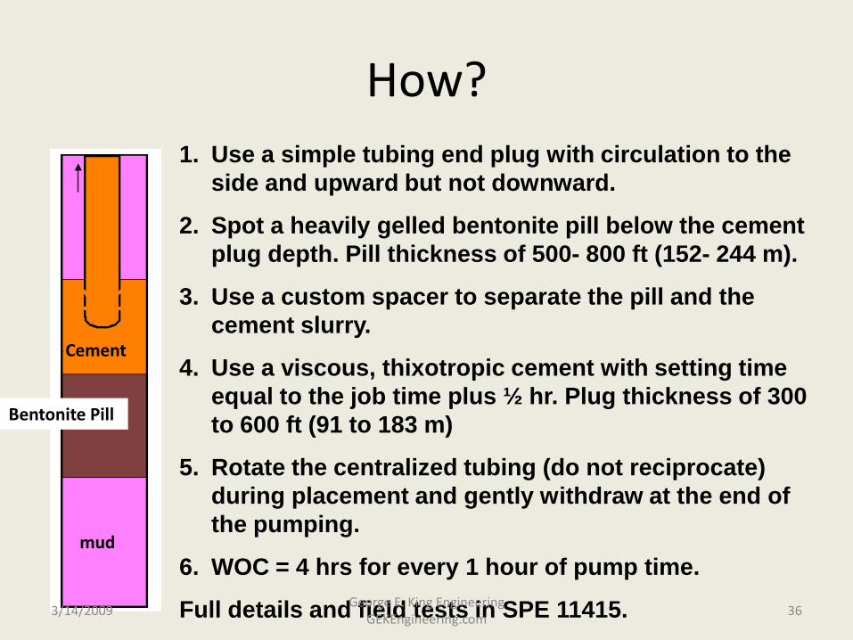
How?1. Use a simple tubing end plug with circulation to the
side and upward but not downward.
2. Spot a heavily gelled bentonite pill below the cement plug depth. Pill thickness of 500- 800 ft (152- 244 m).
3. Use a custom spacer to separate the pill and the cement slurry.
4. Use a viscous, thixotropic cement with setting time equal to the job time plus ½ hr. Plug thickness of 300 to 600 ft (91 to 183 m)
5. Rotate the centralized tubing (do not reciprocate) during placement and gently withdraw at the end of the pumping.
6. WOC = 4 hrs for every 1 hour of pump time.
Full details and field tests in SPE 11415.
Bentonite Pill
mud
Cement
3/14/2009 36George E. King Engineering
GEKEngineering.com

Diverter Plug on End of Tubing
A simplified diverter tool can be made by plugging the end of tubing and drilling 8 holes – the bottom four straight out and the top four angled up at 45o.
Holes are 0.75 to 1” (2 to 2.5 cm) diameter.
SPE 114153/14/2009 37George E. King Engineering
GEKEngineering.com

1. Modify the tubing to bull plug the bottom and open a side port2. Pump a 20 bbl pill of heavily gelled bentonite, same density as the mud in the hole3. Spot the cement slurry on top of the pill while slowly withdrawing the tubing.
3/14/2009 38George E. King Engineering
GEKEngineering.com

Composite Plug Data – Drillable
Plug MkrPlug Type Plug Size
Csg wt range lb/ft
Max Csg ID
Min Csg ID Length
Max Rec Temp
Max Pressure from above
Halliburton Std 4-1/2" 9.5-13.54.09"
103.9 mm3.92"
99.6 mm 28.62"
726.9mm50-250F 10-121C
5,000 psi 34,474 kpa
Halliburton Std 5-1/2" 15.5 - 23.04.95"
123.7 mm4.67"
118.6 mm29.09"
713.9 mm50-250F 10-121C
5,000 psi 34,474 kpa
Halliburton HTHP 4-1/2" 9.5-13.54.09"
103.9 mm3.92"
99.6 mm 27.92"
709.2mm50-350F 10-177C
10,000 psi 68,947 kpa
Halliburton HTHP 5-1/2" 15.5 - 23.04.95"
123.7 mm4.67"
118.6 mm29.87"
758.7 mm50-350F 10-177C
10,000 psi 68,947 kpa
Note the temperature limits. These have proved optimistic in a few HT wells. Milling time to remove these plugs with CT milling tools will be about 1 hour or less with the right mills, equipment and operator.
3/14/2009 39George E. King Engineering
GEKEngineering.com

Example of the force generated by pulling a plug without equalizing pressures below and above the plug
2500 psi
500 psi
5-1/2” Csg 4.95” ID
Effective area of plug = π id2/4 = 19.24 in2
Do a net force balance:
upward: 2500 psi x 19.24 = 48,100 lb
downward: 500 psi x 19.24 = 9,620 lb
Net force (upward) = 38,480 lb
Now, what happens if plug anchors are released before pressure is equalized? With wireline as pulling tool?
3/14/2009 40George E. King Engineering
GEKEngineering.com

Pressure Differential
(psi)3-1/2" tube
4-1/2" tube
5-1/2" tube 7" tube
8-5/8" tube
100 703 1253 1923 3737 4961500 3514 6264 9617 18687 24807
1000 7027 12529 19234 37374 496145000 35137 62643 96172 186869 248070
Theoretical loads (in lbs) resulting from pressure differentials in various sizes of plugs.
The common element on all plugs that must be pulled is that there must be a reliable way to release the pressure below the plug before releasing the locking mechanism on the plug.
3/14/2009 41George E. King Engineering
GEKEngineering.com

Swab/Surge Forces
• “Plunger force” - tremendous force exerted event in small movements because of large area affected.
• Close clearances and high tool movement speeds increase the swab/surge force
• Circulation while pulling lessens swab/surge loads
3/14/2009 42George E. King Engineering
GEKEngineering.com

Quiz – Plugs and Profiles
• What is one of the most common well problems that affects both setting and retrieving a plug?
• What seal material is acceptable for aromatics such as xylene?
• What problem does long term exposure to gas cause in pulling a plug?
• What type of device is recommended for hanging a short tailpipe from a profile with a No-Go shoulder?
3/14/2009 43George E. King Engineering
GEKEngineering.com