pm1000+ power analyzer user manual · pm1000+ power analyzer user manual ' voltech 2007 page...
TRANSCRIPT

PM1000+ Power Analyzer User Manual © Voltech 2007 Page I
PM1000+ POWER ANALYZER
USER MANUAL
Voltech Instruments Inc.11637 Kelly road, Suite 306
Fort Myers, FL33908 U.S.A.
Tel: 239 437 0494 Fax: 239 437 3841 [email protected]
Voltech Instruments Ltd. 148 Harwell Business Centre
Didcot, Oxon, OX11 0RA U.K.
Tel: +44 1235 834555 Fax: +44 1235 835016 [email protected]
www.voltech.com
Need help?
Thank you for choosing to use this Voltech Power Analyzer. It has
been designed to be safe and easy to use.
Should you experience any difficulty during the set up or use of any
Voltech product, or are unsure of any of their features or abilities,
please do not hesitate to contact either your local supplier or visit
our applications support center at www.voltech.com
Page II © Voltech 2007 PM1000+ Power Analyzer User Manual
Voltech Instruments is committed to a policy of continuous product development.
Hence product specification and the information given in this manual are subject to
change without notice.
No part of this publication may be reproduced, stored in a retrieval system, or
transmitted in any form, or by means electronic, mechanical photocopying,
recording or otherwise, without prior written permission of Voltech Instruments.
2007 Voltech Instruments. All rights reserved.
Microsoft, Windows and the Windows logo are either registered trademarks or
trademarks of Microsoft Corporation in the United States and/or other countries.
Voltech Part Number: 98-115
Manual Issue PM1000+ Firmware Revision1 V4.07
For the latest version of the manual and firmware please see our website at
www.voltech.com
PM1000+ Power Analyzer User Manual © Voltech 2007 Page III
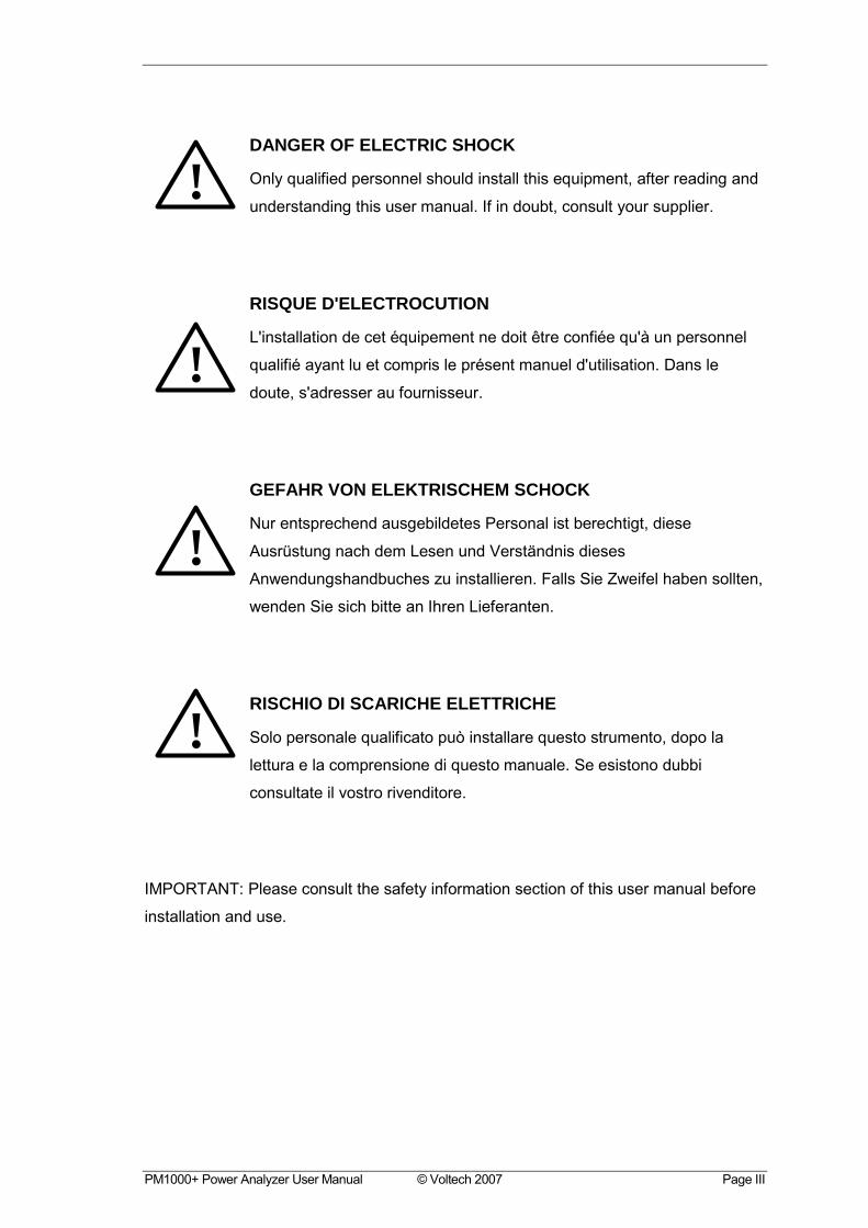
DANGER OF ELECTRIC SHOCK
Only qualified personnel should install this equipment, after reading and
understanding this user manual. If in doubt, consult your supplier.
RISQUE D'ELECTROCUTION
L'installation de cet équipement ne doit être confiée qu'à un personnel
qualifié ayant lu et compris le présent manuel d'utilisation. Dans le
doute, s'adresser au fournisseur.
GEFAHR VON ELEKTRISCHEM SCHOCK
Nur entsprechend ausgebildetes Personal ist berechtigt, diese
Ausrüstung nach dem Lesen und Verständnis dieses
Anwendungshandbuches zu installieren. Falls Sie Zweifel haben sollten,
wenden Sie sich bitte an Ihren Lieferanten.
RISCHIO DI SCARICHE ELETTRICHE
Solo personale qualificato può installare questo strumento, dopo la
lettura e la comprensione di questo manuale. Se esistono dubbi
consultate il vostro rivenditore.
IMPORTANT: Please consult the safety information section of this user manual before
installation and use.
!
!
!
!

Page IV © Voltech 2007 PM1000+ Power Analyzer User Manual
PM1000+ Power Analyzer User Manual © Voltech 2007 Page V
Contents
1. Introduction ............................................................................................... 1-1
1.1. Features & Abilities ......................................................................................... 1-1
1.2. Package Contents........................................................................................... 1-2
1.3. Accessories .................................................................................................... 1-2
2. Quick Start ................................................................................................. 2-1
2.1. Power On........................................................................................................ 2-1
2.2. Connecting to the Product Under Test ............................................................ 2-2
2.3. Default Measurements.................................................................................... 2-3
2.4. Navigating the Menu System .......................................................................... 2-4
2.5. Menu Keys...................................................................................................... 2-5
2.6. Example: Choosing Measurements to Display ................................................ 2-5
2.7. Key Shortcuts: ................................................................................................ 2-6
3. Using Voltage and Current Transducers................................................. 3-1
3.1. Input Overview................................................................................................ 3-1
3.2. To connect a Simple Current transfomer......................................................... 3-2
Scaling. .......................................................................................................... 3-2
3.3. To connect an external resistive shunt: ........................................................... 3-3
3.4. To connect a transducer with a voltage output ................................................ 3-5
3.5. To connect a Voltage Transformer / Transducer ............................................. 3-6
Scaling. .......................................................................................................... 3-6
4. The Menu System...................................................................................... 4-1
4.1. Navigation....................................................................................................... 4-1
4.2. Menu Items..................................................................................................... 4-1
4.3. Main Menu ...................................................................................................... 4-1
4.4. Measurements. ............................................................................................... 4-1
4.5. Modes............................................................................................................. 4-2
Select Mode................................................................................................... 4-2
Ballast Setup.................................................................................................. 4-2
Page VI © Voltech 2007 PM1000+ Power Analyzer User Manual
Inrush Setup .................................................................................................. 4-2
Standby Power Setup .................................................................................... 4-3
Integrator Setup ............................................................................................. 4-3
4.6. Inputs.............................................................................................................. 4-3
Fixed/Auto Ranging ....................................................................................... 4-3
Scaling........................................................................................................... 4-3
Frequency Source.......................................................................................... 4-4
Shunts ........................................................................................................... 4-4
Blanking......................................................................................................... 4-4
4.7. Graphs............................................................................................................ 4-4
Waveform Graph............................................................................................ 4-5
Harmonic Bar Chart ....................................................................................... 4-5
Integration Graph ........................................................................................... 4-5
4.8. Interfaces. ....................................................................................................... 4-5
RS232 Baud Rate .......................................................................................... 4-5
GPIB Address ................................................................................................ 4-6
4.9. User Configuration. ......................................................................................... 4-6
4.10. System Configuration.................................................................................... 4-6
Auto Zero....................................................................................................... 4-6
Clock Setup ................................................................................................... 4-6
4.11. View.............................................................................................................. 4-7
Zoom ............................................................................................................. 4-7
Contrast ......................................................................................................... 4-7
5. Remote Operation ..................................................................................... 5-1
5.1. Overview......................................................................................................... 5-1
5.2. Command Listing ............................................................................................ 5-1
5.3. Communications examples. ............................................................................ 5-5
Basic selection and returning of result............................................................ 5-5
Harmonics...................................................................................................... 5-6
Standby power ............................................................................................... 5-6
Inrush............................................................................................................. 5-7
6. Specification .............................................................................................. 6-1
PM1000+ Power Analyzer User Manual © Voltech 2007 Page VII
6.1. Mechanical...................................................................................................... 6-1
6.2. Power Supply.................................................................................................. 6-1
6.3. Communications ............................................................................................. 6-1
RS232............................................................................................................ 6-1
AUX/TRIG...................................................................................................... 6-2
GPIB.............................................................................................................. 6-2
USB ............................................................................................................... 6-2
6.4. Measured Parameters..................................................................................... 6-3
6.5. Measurement Accuracy .................................................................................. 6-5
7. Warranty, Service and Updates ............................................................... 7-1
7.1. Warranty ......................................................................................................... 7-1
7.2. Calibration and Service ................................................................................... 7-1
7.3. Obtaining Service and Applications Support ................................................... 7-2
7.4. Updating Firmware.......................................................................................... 7-2
8. Safety Information..................................................................................... 8-1
8.1. Safety Features .............................................................................................. 8-1
8.2. Safety Instructions .......................................................................................... 8-1
8.3. Declaration of Conformity................................................................................ 8-2

Page VIII © Voltech 2007 PM1000+ Power Analyzer User Manual

INTRODUCTION
PM1000+ Power Analyzer User Manual © Voltech 2007 Page 1-1
1. INTRODUCTION
1.1. FEATURES & ABILITIES
The Voltech PM1000+ is a powerful and versatile precision power analyzer. Designed
to provide clear and accurate measurements of electrical power and energy on all
electrical products, the PM1000+ is both an easy to use bench instrument and a fast
and programmable automatic test interface.
Basic Features:
• Measures Watts, Volts, Amps, Volt-Amperes and Power Factor.
Always accurate, even on distorted waveforms.
• Range of measurement from milli-watts to mega-watts.
• Built-in energy analyzer (watt-hour integrator) for measuring energy
consumption over time.
• Standby power measurement mode for fast and accurate low power
measurements.
• Harmonic analyzer with built in spectrum display
• Bright color display
• Comprehensive range of computer interfaces including RS232, IEEE488 and
USB
• Inrush current measurement mode for measuring switch-on and other transient
peak currents.
• Ballast mode for measuring the tube power of electronic ballasts.
• Easy-to-use menu system with context-sensitive help.
INTRODUCTION
Page 1-2 © Voltech 2007 PM1000+ Power Analyzer User Manual
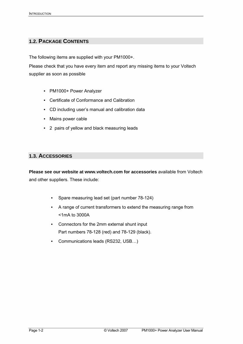
1.2. PACKAGE CONTENTS
The following items are supplied with your PM1000+.
Please check that you have every item and report any missing items to your Voltech
supplier as soon as possible
• PM1000+ Power Analyzer
• Certificate of Conformance and Calibration
• CD including users manual and calibration data
• Mains power cable
• 2 pairs of yellow and black measuring leads
1.3. ACCESSORIES
Please see our website at www.voltech.com for accessories available from Voltech
and other suppliers. These include:
• Spare measuring lead set (part number 78-124)
• A range of current transformers to extend the measuring range from
<1mA to 3000A
• Connectors for the 2mm external shunt input
Part numbers 78-128 (red) and 78-129 (black).
• Communications leads (RS232, USB)

QUICK START
PM1000+ Power Analyzer User Manual © Voltech 2007 Page 2-1
!
2. QUICK START
2.1. POWER ON
1. Check the power analyser is in good condition with no signs of damage.
2. Connect the line power supply cable.
3. Ensure the supply is Earth grounded.
4. Press the power switch at the front to on (I)
The PM1000+ will start its power up sequence. This takes approximately
one minute.
During power up you will see the PM1000+s serial number and last
calibration date.
5. The instrument is now ready for use
QUICK START
Page 2-2 © Voltech 2007 PM1000+ Power Analyzer User Manual
!
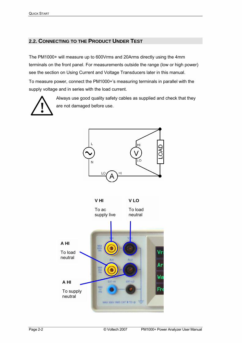
2.2. CONNECTING TO THE PRODUCT UNDER TEST
The PM1000+ will measure up to 600Vrms and 20Arms directly using the 4mm
terminals on the front panel. For measurements outside the range (low or high power)
see the section on Using Current and Voltage Transducers later in this manual.
To measure power, connect the PM1000+s measuring terminals in parallel with the
supply voltage and in series with the load current.
Always use good quality safety cables as supplied and check that they
are not damaged before use.
A HI
To supply neutral
V HI
To ac supply live
V LO
To load neutral
A HI
To load neutral
Quick Start
PM1000+ Power Analyzer User Manual © Voltech 2007 Page 2-3
The simplest and safest way to make a connection to the
product under test is to use a Voltech Break Out Box. This
provides a line socket for connection of the product and 4 x
4mm sockets for direct connection to the PM1000+
terminals as described above.
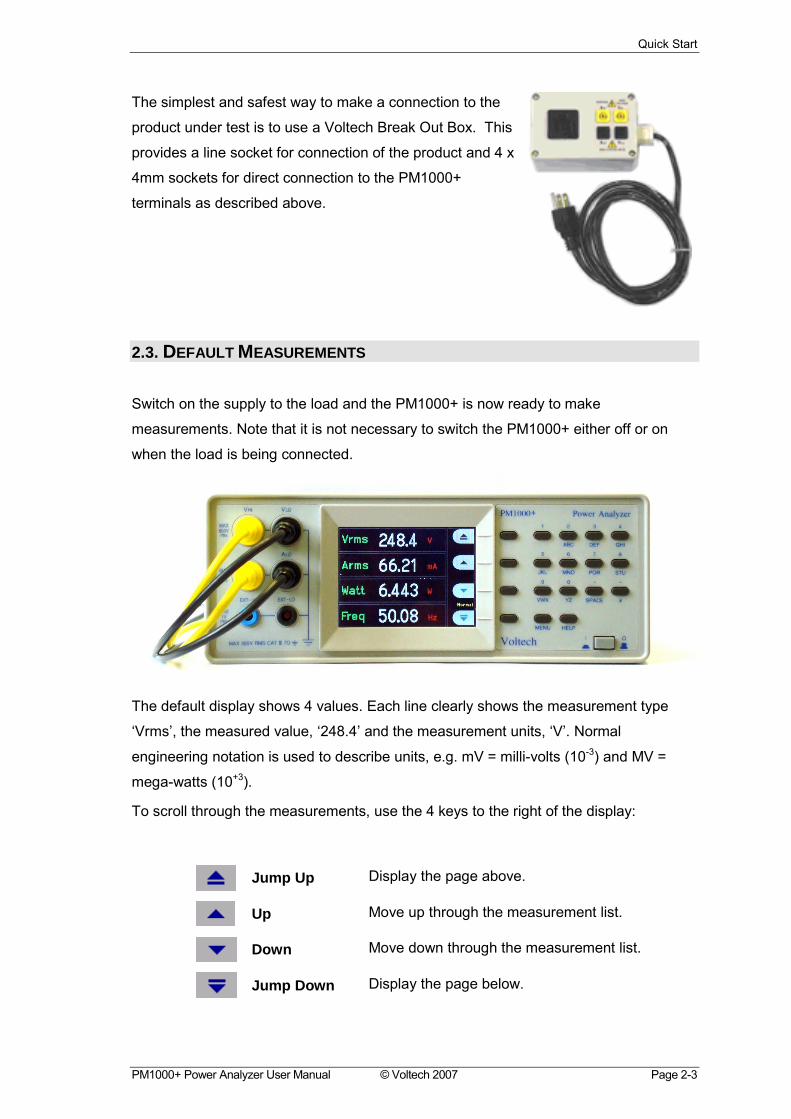
2.3. DEFAULT MEASUREMENTS
Switch on the supply to the load and the PM1000+ is now ready to make
measurements. Note that it is not necessary to switch the PM1000+ either off or on
when the load is being connected.
The default display shows 4 values. Each line clearly shows the measurement type
Vrms, the measured value, 248.4 and the measurement units, V. Normal
engineering notation is used to describe units, e.g. mV = milli-volts (10-3) and MV =
mega-watts (10+3).
To scroll through the measurements, use the 4 keys to the right of the display:
Jump Up Display the page above.
Up Move up through the measurement list.
Down Move down through the measurement list.
Jump Down Display the page below.
QUICK START
Page 2-4 © Voltech 2007 PM1000+ Power Analyzer User Manual
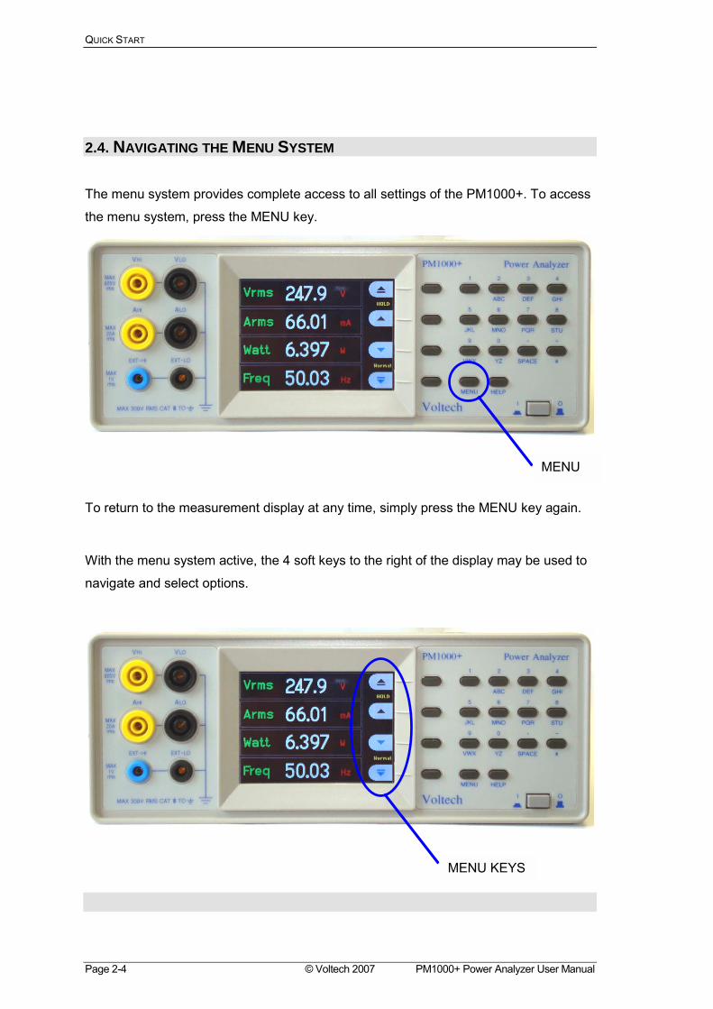
2.4. NAVIGATING THE MENU SYSTEM
The menu system provides complete access to all settings of the PM1000+. To access
the menu system, press the MENU key.
To return to the measurement display at any time, simply press the MENU key again.
With the menu system active, the 4 soft keys to the right of the display may be used to
navigate and select options.
MENU
MENU KEYS
Quick Start
PM1000+ Power Analyzer User Manual © Voltech 2007 Page 2-5
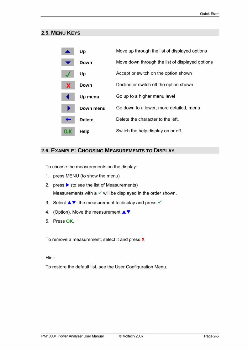
2.5. MENU KEYS
Up Move up through the list of displayed options
Down Move down through the list of displayed options
Up Accept or switch on the option shown
Down Decline or switch off the option shown
Up menu Go up to a higher menu level
Down menu Go down to a lower, more detailed, menu
Delete Delete the character to the left.
Help Switch the help display on or off.
2.6. EXAMPLE: CHOOSING MEASUREMENTS TO DISPLAY
To choose the measurements on the display:
1. press MENU (to show the menu)
2. press ! (to see the list of Measurements)
Measurements with a !!!! will be displayed in the order shown.
3. Select "# the measurement to display and press !!!!.
4. (Option). Move the measurement "#
5. Press OK.
To remove a measurement, select it and press X
Hint:
To restore the default list, see the User Configuration Menu.
QUICK START
Page 2-6 © Voltech 2007 PM1000+ Power Analyzer User Manual
2.7. KEY SHORTCUTS:
Display freeze: Press SPACE
Display graph: Press YZ
Print: Press VWX
Local control (from remote): Press #
USING VOLTAGE AND CURRENT TRANSDUCERS
PM1000+ Power Analyzer User Manual © Voltech 2007 Page 3-1
3. USING VOLTAGE AND CURRENT TRANSDUCERS 3.1. INPUT OVERVIEW
Voltage
Voltages of up to 600V rms may be connected directly to the black and yellow 4mm
VHI and VLO safety sockets at the front of the PM1000+
Current
Currents of up to 20A rms may be connected directly to the black and yellow 4mm AHI
and ALO safety sockets at the front of the PM1000+
External Current Inputs
The external current inputs accept a voltage of up to 1V rms that is proportional to the
current being measured. This input allows a very wide range of external current
transducers to be connected, from low mA current shunts to MA current transformers.
For each type of transducer, the PM1000+ may be scaled to read the correct current.
See the INPUTS menu.
The choice of current transducer will depend on:
• The current being measured, including peaks and transients.
• The accuracy required.
• The bandwidth required: Unless the waveforms are purely sinusoidal, a bandwidth
in excess of the fundamental frequency will be required.
• Whether there is DC current present.
• Convenience of connection E.g. using a clamp-on current transformer, with jaws
that open, for quick connection in a fixed wiring loom.
• The effect of the transducer on the circuit.
USING VOLTAGE AND CURRENT TRANSDUCERS
Page 3-2 © Voltech 2007 PM1000+ Power Analyzer User Manual
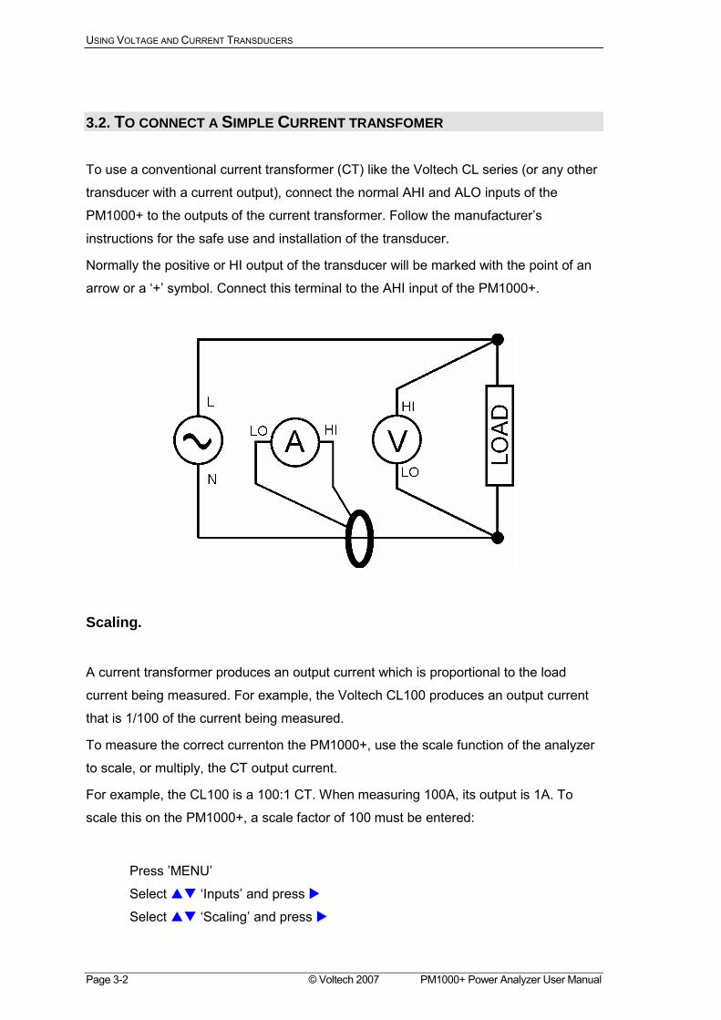
3.2. TO CONNECT A SIMPLE CURRENT TRANSFOMER
To use a conventional current transformer (CT) like the Voltech CL series (or any other
transducer with a current output), connect the normal AHI and ALO inputs of the
PM1000+ to the outputs of the current transformer. Follow the manufacturers
instructions for the safe use and installation of the transducer.
Normally the positive or HI output of the transducer will be marked with the point of an
arrow or a + symbol. Connect this terminal to the AHI input of the PM1000+.
Scaling.
A current transformer produces an output current which is proportional to the load
current being measured. For example, the Voltech CL100 produces an output current
that is 1/100 of the current being measured.
To measure the correct currenton the PM1000+, use the scale function of the analyzer
to scale, or multiply, the CT output current.
For example, the CL100 is a 100:1 CT. When measuring 100A, its output is 1A. To
scale this on the PM1000+, a scale factor of 100 must be entered:
Press MENU
Select "# Inputs and press !
Select "# Scaling and press !
USING VOLTAGE AND CURRENT TRANSDUCERS
PM1000+ Power Analyzer User Manual © Voltech 2007 Page 3-3
Use the delete key to clear the entry.
Type the new scale factor (100)
Press OK
Press MENU to return to the measurement display.
The PM1000+ is now ready to make measurements using a CT.
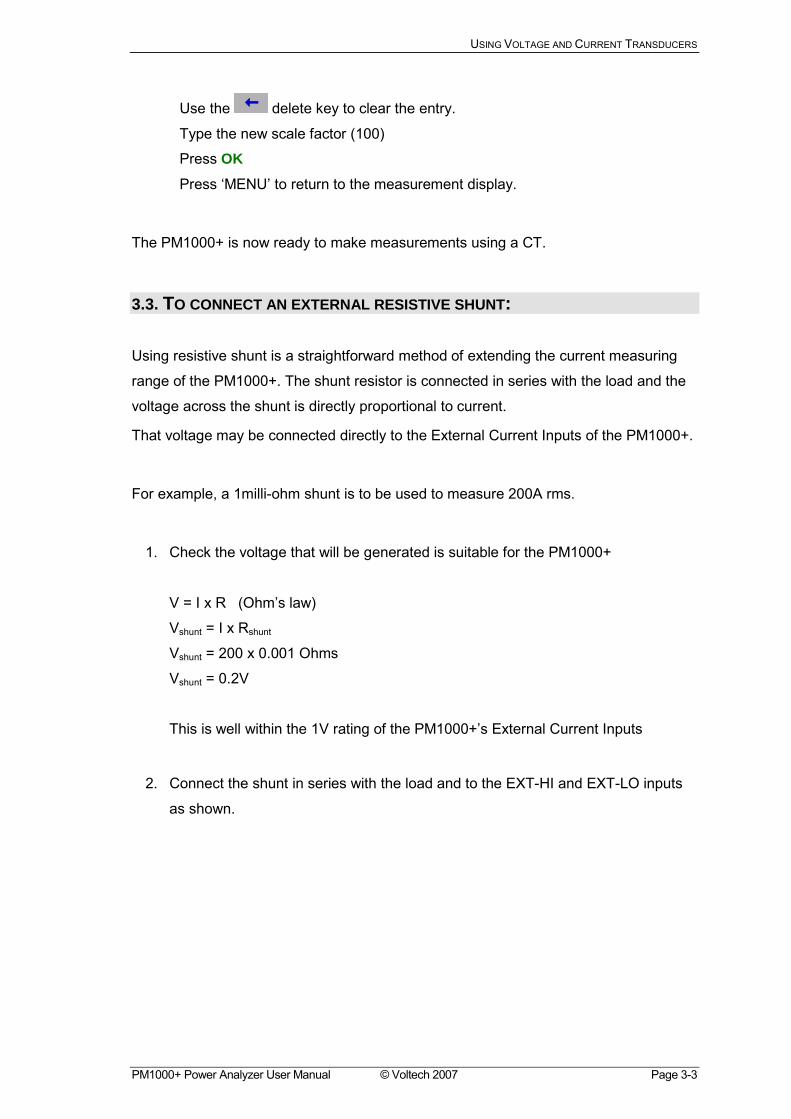
3.3. TO CONNECT AN EXTERNAL RESISTIVE SHUNT:
Using resistive shunt is a straightforward method of extending the current measuring
range of the PM1000+. The shunt resistor is connected in series with the load and the
voltage across the shunt is directly proportional to current.
That voltage may be connected directly to the External Current Inputs of the PM1000+.
For example, a 1milli-ohm shunt is to be used to measure 200A rms.
1. Check the voltage that will be generated is suitable for the PM1000+
V = I x R (Ohms law)
Vshunt = I x Rshunt
Vshunt = 200 x 0.001 Ohms
Vshunt = 0.2V
This is well within the 1V rating of the PM1000+s External Current Inputs
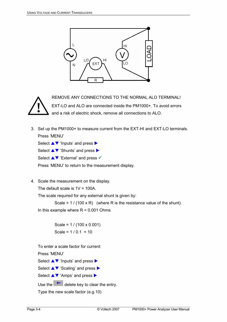
2. Connect the shunt in series with the load and to the EXT-HI and EXT-LO inputs
as shown.
USING VOLTAGE AND CURRENT TRANSDUCERS
Page 3-4 © Voltech 2007 PM1000+ Power Analyzer User Manual
REMOVE ANY CONNECTIONS TO THE NORMAL ALO TERMINAL!
EXT-LO and ALO are connected inside the PM1000+. To avoid errors
and a risk of electric shock, remove all connections to ALO.
3. Set up the PM1000+ to measure current from the EXT-HI and EXT-LO terminals.
Press MENU
Select "# Inputs and press !
Select "# Shunts and press !
Select "# External and press !!!!
Press MENU to return to the measurement display.
4. Scale the measurement on the display.
The default scale is 1V = 100A.
The scale required for any external shunt is given by:
Scale = 1 / (100 x R) (where R is the resistance value of the shunt).
In this example where R = 0.001 Ohms
Scale = 1 / (100 x 0.001)
Scale = 1 / 0.1 = 10
To enter a scale factor for current:
Press MENU
Select "# Inputs and press !
Select "# Scaling and press !
Select "# Amps and press !
Use the delete key to clear the entry.
Type the new scale factor (e.g.10)
!
USING VOLTAGE AND CURRENT TRANSDUCERS
PM1000+ Power Analyzer User Manual © Voltech 2007 Page 3-5
Press OK
Press MENU to return to the measurement display.
The PM1000+ is now ready to make measurements using an external shunt.
3.4. TO CONNECT A TRANSDUCER WITH A VOLTAGE OUTPUT These transducers contain active circuits that help to improve performance at high
bandwidth. They may be of the hall effect or Rogowski coil type.
The procedure is similar to that of installing an external shunt as described above.
1. Follow the manufacturers instructions for the safe use and installation of the
transducer.
2. Connect the voltage output to the EXT-HI and EXT-LO terminals of the
PM1000++ channel as above.
3. Select Inputs Shunts External as above.
Press MENU
Select "# Inputs and press !
Select "# Shunts and press !
Select "# External and press !!!!
Press MENU to return to the measurement display.
4. Select and input a scale factor. These types of transducers are often rated in
terms of mV / amp. For example a transducer with an output of 100mV / amp is
the equivalent of a 100 milli-ohm external shunt resistor.
Scale = 1 / (100 x R) (where R is the resistance value of the shunt).
In this example where R = 0.1 Ohms
Scale = 1 / (100 x 0.1)
Scale = 1 / 10 = 0.1
Press MENU
Select "# Inputs and press !
Select "# Scaling and press !
Select "# Amps and press !
Use the delete key to clear the entry.
Type the new scale factor (e.g. 0.1)
Press OK
USING VOLTAGE AND CURRENT TRANSDUCERS
Page 3-6 © Voltech 2007 PM1000+ Power Analyzer User Manual
5. Press MENU to return to the measurement display.
The PM1000+ is now ready to make measurements using a current transducer with a
voltage output.
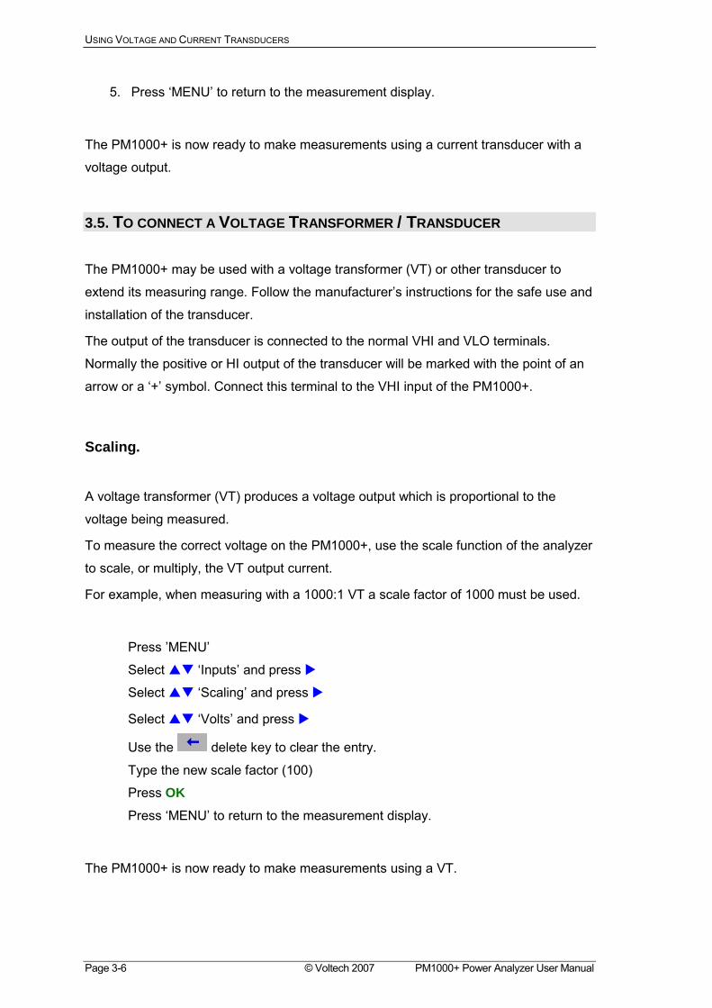
3.5. TO CONNECT A VOLTAGE TRANSFORMER / TRANSDUCER
The PM1000+ may be used with a voltage transformer (VT) or other transducer to
extend its measuring range. Follow the manufacturers instructions for the safe use and
installation of the transducer.
The output of the transducer is connected to the normal VHI and VLO terminals.
Normally the positive or HI output of the transducer will be marked with the point of an
arrow or a + symbol. Connect this terminal to the VHI input of the PM1000+.
Scaling.
A voltage transformer (VT) produces a voltage output which is proportional to the
voltage being measured.
To measure the correct voltage on the PM1000+, use the scale function of the analyzer
to scale, or multiply, the VT output current.
For example, when measuring with a 1000:1 VT a scale factor of 1000 must be used.
Press MENU
Select "# Inputs and press !
Select "# Scaling and press !
Select "# Volts and press !
Use the delete key to clear the entry.
Type the new scale factor (100)
Press OK
Press MENU to return to the measurement display.
The PM1000+ is now ready to make measurements using a VT.

USING VOLTAGE AND CURRENT TRANSDUCERS
PM1000+ Power Analyzer User Manual © Voltech 2007 Page 3-7

USING VOLTAGE AND CURRENT TRANSDUCERS
Page 3-8 © Voltech 2007 PM1000+ Power Analyzer User Manual
THE MENU SYSTEM
PM1000+ Power Analyzer User Manual © Voltech 2007 Page 4-1
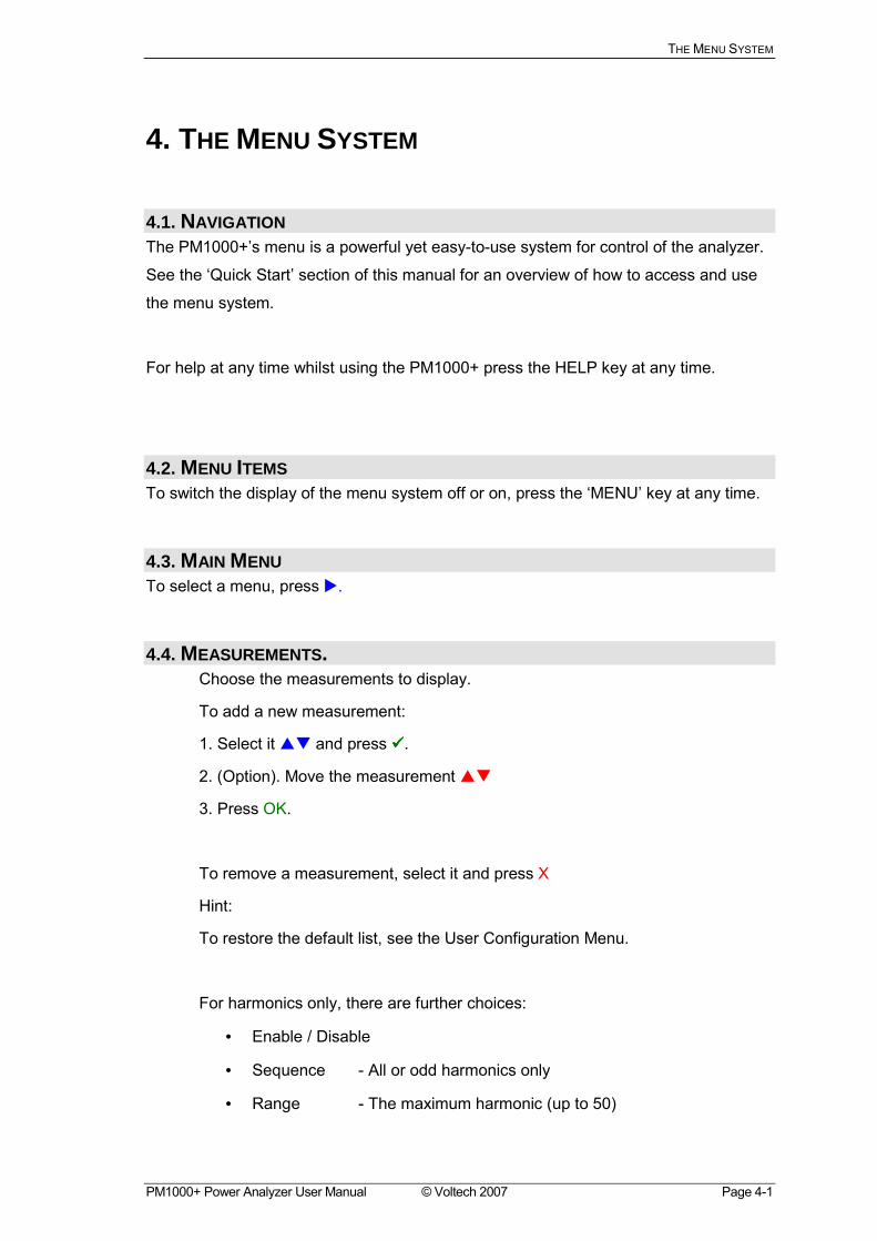
4. THE MENU SYSTEM
4.1. NAVIGATION The PM1000+s menu is a powerful yet easy-to-use system for control of the analyzer.
See the Quick Start section of this manual for an overview of how to access and use
the menu system.
For help at any time whilst using the PM1000+ press the HELP key at any time.
4.2. MENU ITEMS To switch the display of the menu system off or on, press the MENU key at any time.
4.3. MAIN MENU To select a menu, press !.
4.4. MEASUREMENTS. Choose the measurements to display.
To add a new measurement:
1. Select it "# and press !!!!.
2. (Option). Move the measurement "#
3. Press OK.
To remove a measurement, select it and press X
Hint:
To restore the default list, see the User Configuration Menu.
For harmonics only, there are further choices:
• Enable / Disable
• Sequence - All or odd harmonics only
• Range - The maximum harmonic (up to 50)
THE MENU SYSTEM
Page 4-2 © Voltech 2007 PM1000+ Power Analyzer User Manual
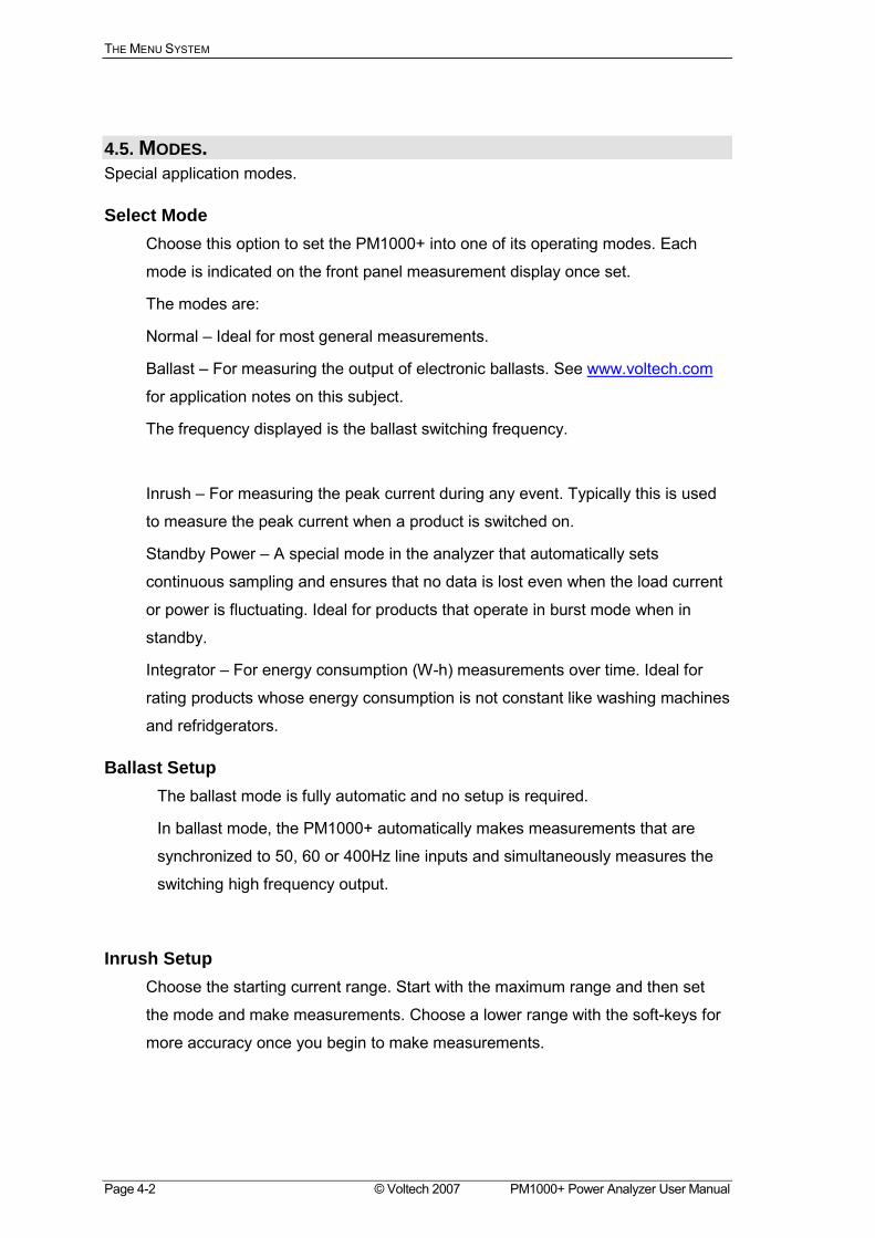
4.5. MODES. Special application modes.
Select Mode Choose this option to set the PM1000+ into one of its operating modes. Each
mode is indicated on the front panel measurement display once set.
The modes are:
Normal Ideal for most general measurements.
Ballast For measuring the output of electronic ballasts. See www.voltech.com
for application notes on this subject.
The frequency displayed is the ballast switching frequency.
Inrush For measuring the peak current during any event. Typically this is used
to measure the peak current when a product is switched on.
Standby Power A special mode in the analyzer that automatically sets
continuous sampling and ensures that no data is lost even when the load current
or power is fluctuating. Ideal for products that operate in burst mode when in
standby.
Integrator For energy consumption (W-h) measurements over time. Ideal for
rating products whose energy consumption is not constant like washing machines
and refridgerators.
Ballast Setup The ballast mode is fully automatic and no setup is required.
In ballast mode, the PM1000+ automatically makes measurements that are
synchronized to 50, 60 or 400Hz line inputs and simultaneously measures the
switching high frequency output.
Inrush Setup Choose the starting current range. Start with the maximum range and then set
the mode and make measurements. Choose a lower range with the soft-keys for
more accuracy once you begin to make measurements.
THE MENU SYSTEM
PM1000+ Power Analyzer User Manual © Voltech 2007 Page 4-3
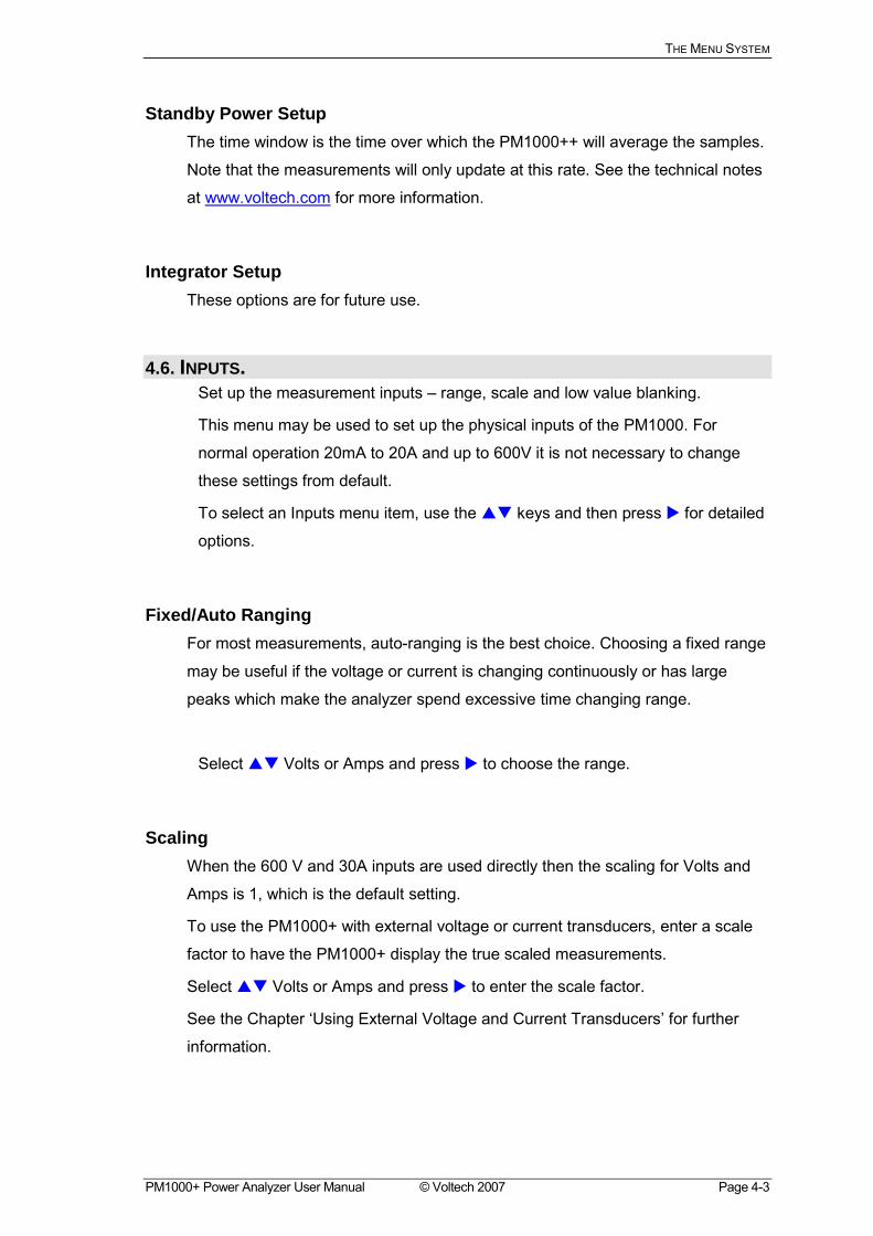
Standby Power Setup The time window is the time over which the PM1000++ will average the samples.
Note that the measurements will only update at this rate. See the technical notes
at www.voltech.com for more information.
Integrator Setup These options are for future use.
4.6. INPUTS. Set up the measurement inputs range, scale and low value blanking.
This menu may be used to set up the physical inputs of the PM1000. For
normal operation 20mA to 20A and up to 600V it is not necessary to change
these settings from default.
To select an Inputs menu item, use the "# keys and then press ! for detailed
options.
Fixed/Auto Ranging For most measurements, auto-ranging is the best choice. Choosing a fixed range
may be useful if the voltage or current is changing continuously or has large
peaks which make the analyzer spend excessive time changing range.
Select "# Volts or Amps and press ! to choose the range.
Scaling When the 600 V and 30A inputs are used directly then the scaling for Volts and
Amps is 1, which is the default setting.
To use the PM1000+ with external voltage or current transducers, enter a scale
factor to have the PM1000+ display the true scaled measurements.
Select "# Volts or Amps and press ! to enter the scale factor.
See the Chapter Using External Voltage and Current Transducers for further
information.
THE MENU SYSTEM
Page 4-4 © Voltech 2007 PM1000+ Power Analyzer User Manual
Frequency Source
To make accurate rms measurements the PM1000+ must first determine
frequency. Normally the PM1000+ detects frequency from the voltage signal
using proprietary algorithms.
If no voltage signal is present, or it is a chopped waveform, then it may be
necessary to select Amps as the frequency source.
Select Volts or Amps Frequency Source using the "# keys and press !!!! to
confirm.
Shunts The internal shunt of the PM1000+ is suitable for measurements in the range
20mA to 20A rms and this may be extended by the use of suitable current
transducers from uA to MA.
Some current transducers (including simple resistive shunts) produce a voltage
that is proportional to current. External Shunt Inputs are provided on the
PM1000+ for use with current transducers that provide a voltage output.
Because the 0V is common to both the internal and external shunts, only one
type may be connected at any time.
Select Internal or External Shunt using the "# keys and press !!!! to confirm.
See the Chapter Using External Voltage and Current Transducers for further
information.
Blanking Normally Enabled, select Disable to measure voltage or current that is small
(<0.25V or <3mA). If blanking operates on either voltage or current then all
related measurements will be blanked including W, VA and PF.
Select Disable or Enable using the "# keys and press !!!! to confirm.
4.7. GRAPHS. Set up the graphical displays of the PM1000+
Select the graph type using the "# keys and press ! for options.
HINT: Use the YZ key to toggle between graphic and numeric displays.
THE MENU SYSTEM
PM1000+ Power Analyzer User Manual © Voltech 2007 Page 4-5
Waveform Graph This will display the voltage, current and (optionally) the watts waveform.
The scale of the graph is set automatically according to the selected range and
scaling. Display of the Watts graph may be disabled.
Select "# Show and press !!!! to display the Waveform Graph.
Select Watts to add the instantaneous watts waveform to the display.
Harmonic Bar Chart Select Voltage or Current harmonic barchart using the "# keys and press ! for
details.
The scale is the maximum amplitude that will be displayed. Set the scale to be
similar to the rms value to see an overview of the spectrum. To view smaller
harmonics in more detail a smaller scale may be set.
If the harmonic exceeds the set scale it will be shown as a grey bar.
The right $ and left % arrow keys may be used to select the harmonic whose
amplitude and phase are shown at the top of the screen. The selected harmonic
is shown in yellow.
Select "# Show and press !!!! to display the harmonic barchart (voltage or
current).
Integration Graph This function will be available in a future release of firmware.
4.8. INTERFACES. This menu may be used to set up the interfaces of the PM1000+
To select set up an interface, use the "# keys and then press ! for detailed options.
RS232 Baud Rate Select "# the desired baud rate and press !!!! to confirm.
9600, 19200 (default) and 38400 are available.
The PM1000++ uses hardware handshaking (RTS / CTS) with no parity, 8 data
bits and 1stop bit (N,8,1).
THE MENU SYSTEM
Page 4-6 © Voltech 2007 PM1000+ Power Analyzer User Manual
GPIB Address Enter the GPIB address and press OK.
Default address is 6.
4.9. USER CONFIGURATION. Save and recall your set up.
To select a menu item, use the "# keys and then press ! for detailed options.
The first option is to Load Default. Choosing this option will set every menu
option of the PM1000+ to its factory default.
The other menu items (Default Configuration n) may be used to store and
recall all settings of the PM1000+
For each User Configuration, you may:
Apply apply the saved configuration
Rename give the configuration an meaningful name
Save Current save a configuration. This is always the complete settings of the
PM1000+ at the time you choose this option.
Print Print the configuration.
4.10. SYSTEM CONFIGURATION. Set up Clock and Auto Zero.
To select a menu item, use the "# keys and then press ! for detailed options.
Auto Zero Normally the PM1000+ will cancel any small dc offsets in the measurement
automatically. This is called Auto Zero.
Auto Zero should always be enabled.
Select "# Disable and Enable and press !!!! to confirm.
Clock Setup These options may be used to check or set the PM1000+s internal clock.
To select a menu item, use the "# keys and then press ! for detailed options.
THE MENU SYSTEM
PM1000+ Power Analyzer User Manual © Voltech 2007 Page 4-7
Set Time - Enter the time using the format shown and press OK to confirm.
Set Date - Enter the date using the format shown and press OK to confirm.
Time Format - Select "# 12 Hour or 24 Hour and press !!!! to confirm.
Date Format - Select "# the required date format and press !!!! to confirm.
4.11. VIEW. Set up zoom and contrast.
To select a menu item, use the "# keys and then press ! for detailed options.
Zoom Select "# either 4 results or 14 results display and press !!!! to confirm.
Contrast Enter a contrast number and press OK to confirm.
50 is the default value.

THE MENU SYSTEM
Page 4-8 © Voltech 2007 PM1000+ Power Analyzer User Manual
REMOTE OPERATIION
PM1000+ Power Analyzer User Manual © Voltech 2007 Page 5-1
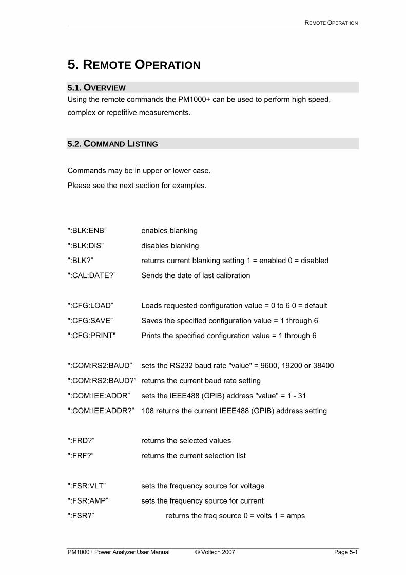
5. REMOTE OPERATION 5.1. OVERVIEW Using the remote commands the PM1000+ can be used to perform high speed,
complex or repetitive measurements.
5.2. COMMAND LISTING
Commands may be in upper or lower case.
Please see the next section for examples.
":BLK:ENB enables blanking
":BLK:DIS disables blanking
":BLK? returns current blanking setting 1 = enabled 0 = disabled
":CAL:DATE? Sends the date of last calibration
":CFG:LOAD Loads requested configuration value = 0 to 6 0 = default
":CFG:SAVE Saves the specified configuration value = 1 through 6
":CFG:PRINT" Prints the specified configuration value = 1 through 6
":COM:RS2:BAUD sets the RS232 baud rate "value" = 9600, 19200 or 38400
":COM:RS2:BAUD? returns the current baud rate setting
":COM:IEE:ADDR sets the IEEE488 (GPIB) address "value" = 1 - 31
":COM:IEE:ADDR? 108 returns the current IEEE488 (GPIB) address setting
":FRD? returns the selected values
":FRF? returns the current selection list
":FSR:VLT sets the frequency source for voltage
":FSR:AMP sets the frequency source for current
":FSR? returns the freq source 0 = volts 1 = amps
REMOTE OPERATIION
Page 5-2 © Voltech 2007 PM1000+ Power Analyzer User Manual
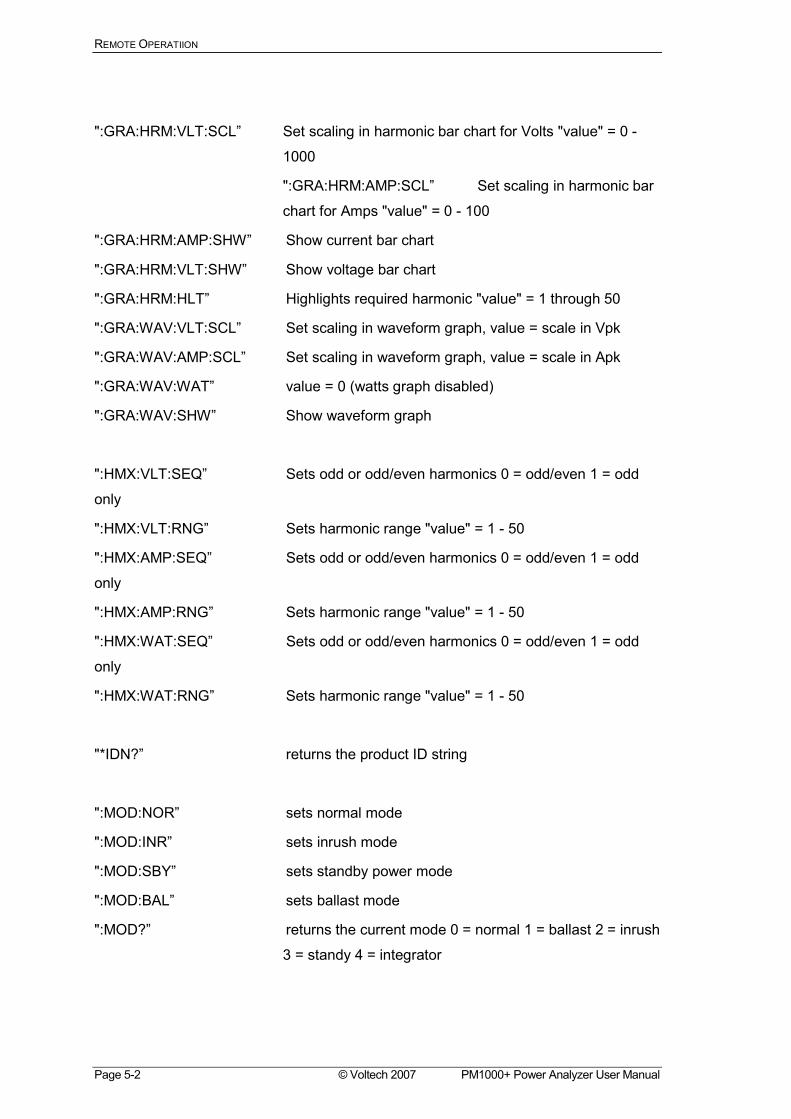
":GRA:HRM:VLT:SCL Set scaling in harmonic bar chart for Volts "value" = 0 -
1000
":GRA:HRM:AMP:SCL Set scaling in harmonic bar
chart for Amps "value" = 0 - 100
":GRA:HRM:AMP:SHW Show current bar chart
":GRA:HRM:VLT:SHW Show voltage bar chart
":GRA:HRM:HLT Highlights required harmonic "value" = 1 through 50
":GRA:WAV:VLT:SCL Set scaling in waveform graph, value = scale in Vpk
":GRA:WAV:AMP:SCL Set scaling in waveform graph, value = scale in Apk
":GRA:WAV:WAT value = 0 (watts graph disabled)
":GRA:WAV:SHW Show waveform graph
":HMX:VLT:SEQ Sets odd or odd/even harmonics 0 = odd/even 1 = odd
only
":HMX:VLT:RNG Sets harmonic range "value" = 1 - 50
":HMX:AMP:SEQ Sets odd or odd/even harmonics 0 = odd/even 1 = odd
only
":HMX:AMP:RNG Sets harmonic range "value" = 1 - 50
":HMX:WAT:SEQ Sets odd or odd/even harmonics 0 = odd/even 1 = odd
only
":HMX:WAT:RNG Sets harmonic range "value" = 1 - 50
"*IDN? returns the product ID string
":MOD:NOR sets normal mode
":MOD:INR sets inrush mode
":MOD:SBY sets standby power mode
":MOD:BAL sets ballast mode
":MOD? returns the current mode 0 = normal 1 = ballast 2 = inrush
3 = standy 4 = integrator
REMOTE OPERATIION
PM1000+ Power Analyzer User Manual © Voltech 2007 Page 5-3
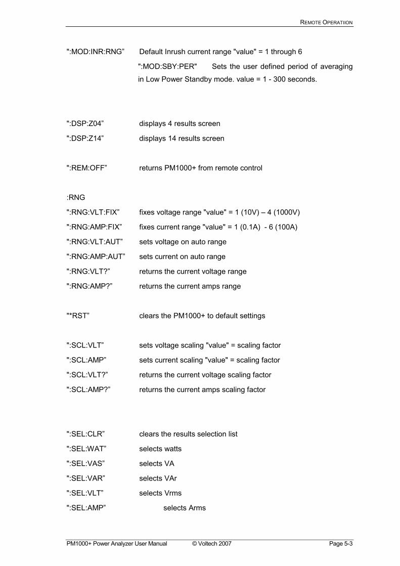
":MOD:INR:RNG Default Inrush current range "value" = 1 through 6
":MOD:SBY:PER" Sets the user defined period of averaging
in Low Power Standby mode. value = 1 - 300 seconds.
":DSP:Z04 displays 4 results screen
":DSP:Z14 displays 14 results screen
":REM:OFF returns PM1000+ from remote control
:RNG
":RNG:VLT:FIX fixes voltage range "value" = 1 (10V) 4 (1000V)
":RNG:AMP:FIX fixes current range "value" = 1 (0.1A) - 6 (100A)
":RNG:VLT:AUT sets voltage on auto range
":RNG:AMP:AUT sets current on auto range
":RNG:VLT? returns the current voltage range
":RNG:AMP? returns the current amps range
"*RST clears the PM1000+ to default settings
":SCL:VLT sets voltage scaling "value" = scaling factor
":SCL:AMP sets current scaling "value" = scaling factor
":SCL:VLT? returns the current voltage scaling factor
":SCL:AMP? returns the current amps scaling factor
":SEL:CLR clears the results selection list
":SEL:WAT selects watts
":SEL:VAS selects VA
":SEL:VAR selects VAr
":SEL:VLT selects Vrms
":SEL:AMP selects Arms
REMOTE OPERATIION
Page 5-4 © Voltech 2007 PM1000+ Power Analyzer User Manual
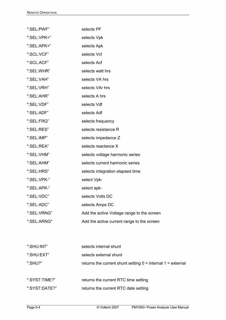
":SEL:PWF selects PF
":SEL:VPK+ selects Vpk
":SEL:APK+ selects Apk
":SCL:VCF selects Vcf
":SCL:ACF selects Acf
":SEL:WHR selects watt hrs
":SEL:VAH selects VA hrs
":SEL:VRH selects VAr hrs
":SEL:AHR selects A hrs
":SEL:VDF selects Vdf
":SEL:ADF selects Adf
":SEL:FRQ selects frequency
":SEL:RES selects resistance R
":SEL:IMP selects impedance Z
":SEL:REA selects reactance X
":SEL:VHM selects voltage harmonic series
":SEL:AHM selects current harmonic series
":SEL:HRS selects integration elapsed time
":SEL:VPK- select Vpk-
":SEL:APK- select apk-
":SEL:VDC selects Volts DC
":SEL:ADC selects Amps DC
":SEL:VRNG Add the active Voltage range to the screen
":SEL:ARNG" Add the active current range to the screen
":SHU:INT selects internal shunt
":SHU:EXT selects external shunt
":SHU? returns the current shunt setting 0 = internal 1 = external
":SYST:TIME? returns the current RTC time setting
":SYST:DATE? returns the current RTC date setting
REMOTE OPERATIION
PM1000+ Power Analyzer User Manual © Voltech 2007 Page 5-5
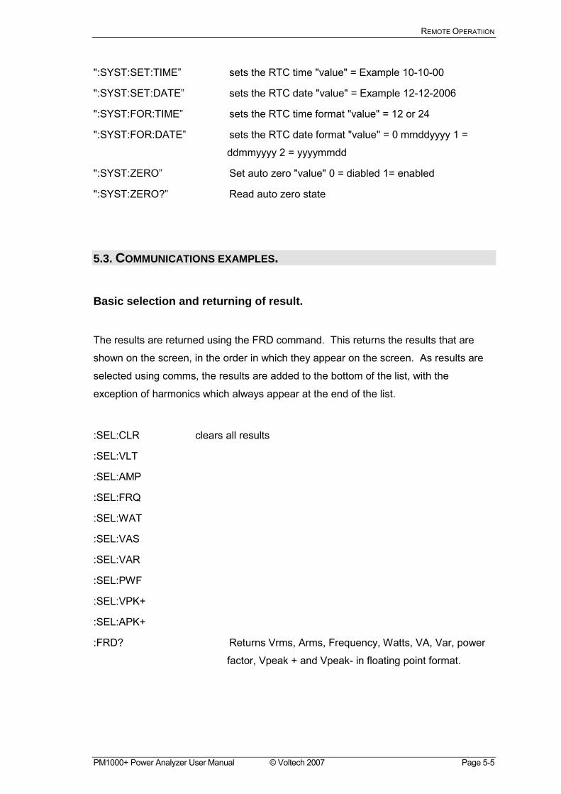
":SYST:SET:TIME sets the RTC time "value" = Example 10-10-00
":SYST:SET:DATE sets the RTC date "value" = Example 12-12-2006
":SYST:FOR:TIME sets the RTC time format "value" = 12 or 24
":SYST:FOR:DATE sets the RTC date format "value" = 0 mmddyyyy 1 =
ddmmyyyy 2 = yyyymmdd
":SYST:ZERO Set auto zero "value" 0 = diabled 1= enabled
":SYST:ZERO? Read auto zero state
5.3. COMMUNICATIONS EXAMPLES.
Basic selection and returning of result.
The results are returned using the FRD command. This returns the results that are
shown on the screen, in the order in which they appear on the screen. As results are
selected using comms, the results are added to the bottom of the list, with the
exception of harmonics which always appear at the end of the list.
:SEL:CLR clears all results
:SEL:VLT
:SEL:AMP
:SEL:FRQ
:SEL:WAT
:SEL:VAS
:SEL:VAR
:SEL:PWF
:SEL:VPK+
:SEL:APK+
:FRD? Returns Vrms, Arms, Frequency, Watts, VA, Var, power
factor, Vpeak + and Vpeak- in floating point format.
REMOTE OPERATIION
Page 5-6 © Voltech 2007 PM1000+ Power Analyzer User Manual
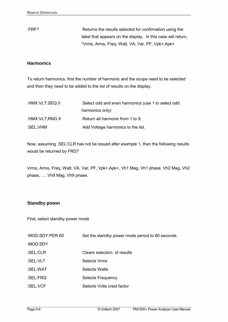
:FRF? Returns the results selected for confirmation using the
label that appears on the display. In this case will return,
Vrms, Arms, Freq, Watt, VA, Var, PF, Vpk+,Apk+
Harmonics
To return harmonics, first the number of harmonic and the scope need to be selected
and then they need to be added to the list of results on the display.
:HMX:VLT:SEQ 0 Select odd and even harmonics (use 1 to select odd
harmonics only)
:HMX:VLT:RNG 9 Return all harmonic from 1 to 9.
:SEL:VHM Add Voltage harmonics to the list.
Now, assuming :SEL:CLR has not be issued after example 1, then the following results
would be returned by FRD?
Vrms, Arms, Freq, Watt, VA, Var, PF, Vpk+,Apk+, Vh1 Mag, Vh1 phase, Vh2 Mag, Vh2
phase, . Vh9 Mag, Vh9 phase.
Standby power
First, select standby power mode
:MOD:SDY:PER 60 Set the standby power mode period to 60 seconds.
:MOD:SDY
:SEL:CLR Clears selection of results
:SEL:VLT Selects Vrms
:SEL:WAT Selects Watts
:SEL:FRQ Selects Frequency
:SEL:VCF Selects Volts crest factor
REMOTE OPERATIION
PM1000+ Power Analyzer User Manual © Voltech 2007 Page 5-7
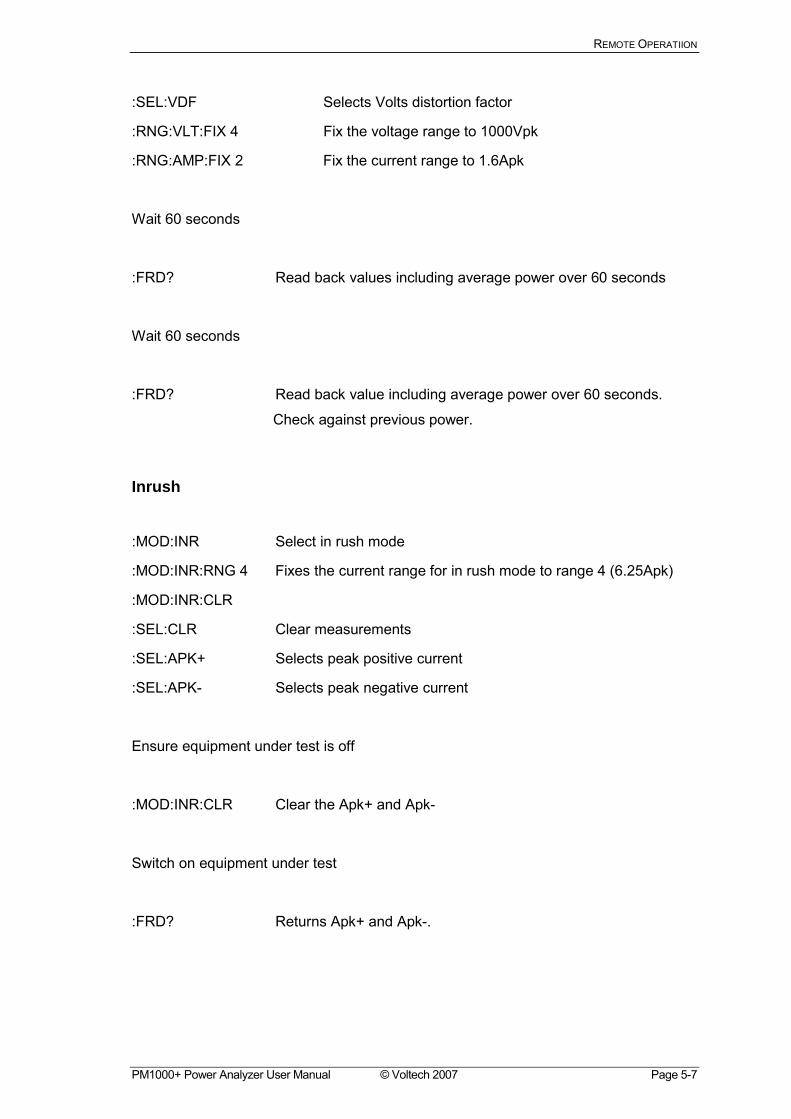
:SEL:VDF Selects Volts distortion factor
:RNG:VLT:FIX 4 Fix the voltage range to 1000Vpk
:RNG:AMP:FIX 2 Fix the current range to 1.6Apk
Wait 60 seconds
:FRD? Read back values including average power over 60 seconds
Wait 60 seconds
:FRD? Read back value including average power over 60 seconds.
Check against previous power.
Inrush
:MOD:INR Select in rush mode
:MOD:INR:RNG 4 Fixes the current range for in rush mode to range 4 (6.25Apk)
:MOD:INR:CLR
:SEL:CLR Clear measurements
:SEL:APK+ Selects peak positive current
:SEL:APK- Selects peak negative current
Ensure equipment under test is off
:MOD:INR:CLR Clear the Apk+ and Apk-
Switch on equipment under test
:FRD? Returns Apk+ and Apk-.

REMOTE OPERATIION
Page 5-8 © Voltech 2007 PM1000+ Power Analyzer User Manual
SPECIFICATION
PM1000+ Power Analyzer User Manual © Voltech 2007 Page 6-1
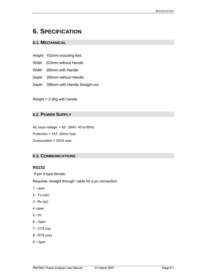
6. SPECIFICATION 6.1. MECHANICAL
Height 102mm Including feet.
Width 223mm without Handle
Width 260mm with Handle
Depth 285mm without Handle
Depth 358mm with Handle Straight out
Weight = 3.2Kg with handle
6.2. POWER SUPPLY
AC input voltage = 85 - 264V, 45 to 65Hz
Protection = 1AT, 20mm fuse
Consumption = 25VA max.
6.3. COMMUNICATIONS
RS232 9-pin d-type female.
Requires straight through cable for a pc connection.
1 - open
2 - Tx (o/p)
3 - Rx (i/p)
4 -open
5 - 0V
6 - Open
7 - CTS (i/p)
8 - RTS (o/p)
9 - Open
SPECIFICATION
Page 6-2 © Voltech 2007 PM1000+ Power Analyzer User Manual
AUX/TRIG For Voltech Use Only.
GPIB To IEEE488 standard.
USB USB 2.0 compatible. Will work with any USB 2.0 system.
Full Speed (12Mbits/sec).
1 - VBus (i/p)
2 - D- (i/p and o/p)
3 - D+ (i/p and o/p)
4 - 0V (i/p)
SPECIFICATION
PM1000+ Power Analyzer User Manual © Voltech 2007 Page 6-3
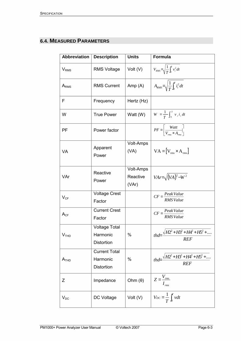
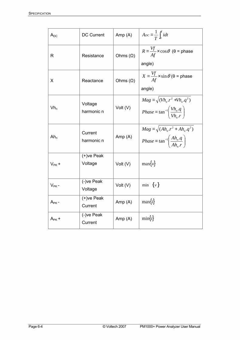
6.4. MEASURED PARAMETERS
Abbreviation Description Units Formula
VRMS RMS Voltage Volt (V) ∫=T
iRMS dtvT
V0
21
ARMS RMS Current Amp (A) ∫=T
iRMS dtiT
A0
21
F Frequency Hertz (Hz)
W True Power Watt (W) ∫=T
ii dtivT
W0
1
PF Power factor
×
=rmsrms AV
WattPF
VA Apparent
Power
Volt-Amps
(VA)
[ ]rmsrms AVVA ×=
VAr Reactive
Power
Volt-Amps
Reactive
(VAr) ( ) 22 WVAVAr −=
VCF Voltage Crest
Factor ValueRMS
ValuePeakCF =
ACF Current Crest
Factor ValueRMS
ValuePeakCF =
VTHD
Voltage Total
Harmonic
Distortion
% REF
....HHHHthd ++++=2222 5432
ATHD
Current Total
Harmonic
Distortion
% REF
HHHHthd ....5432 2222 ++++=
Z Impedance Ohm (θ) rms
rms
IVZ =
VDC DC Voltage Volt (V) ∫=T
DC vdtT
V0
1
SPECIFICATION
Page 6-4 © Voltech 2007 PM1000+ Power Analyzer User Manual
ADC DC Current Amp (A) ∫=T
DC idtT
A0
1
R Resistance Ohms (Ω) θcos×=
AfVfR (θ = phase
angle)
X Reactance Ohms (Ω) θsin×=
AfVfX (θ = phase
angle)
Vhn Voltage
harmonic n Volt (V)
=
+=
−
rVhqVhPhase
qVhrVhMag
n
n
nn
.
.tan
)..(
1
22
Ahn Current
harmonic n Amp (A)
=
+=
−
rAhqAhPhase
qAhrAhMag
n
n
nn
.
.tan
)..(
1
22
VPK +
(+)ve Peak
Voltage
Volt (V) vmax
VPK - (-)ve Peak
Voltage Volt (V) vmin
APK - (+)ve Peak
Current Amp (A) imax
APK + (-)ve Peak
Current Amp (A) imin
SPECIFICATION
PM1000+ Power Analyzer User Manual © Voltech 2007 Page 6-5
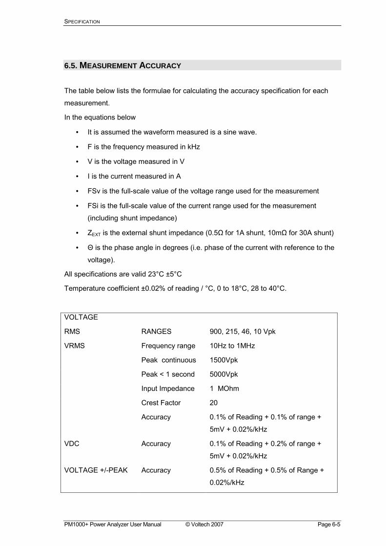
6.5. MEASUREMENT ACCURACY
The table below lists the formulae for calculating the accuracy specification for each
measurement.
In the equations below
• It is assumed the waveform measured is a sine wave.
• F is the frequency measured in kHz
• V is the voltage measured in V
• I is the current measured in A
• FSv is the full-scale value of the voltage range used for the measurement
• FSi is the full-scale value of the current range used for the measurement
(including shunt impedance)
• ZEXT is the external shunt impedance (0.5Ω for 1A shunt, 10mΩ for 30A shunt)
• Θ is the phase angle in degrees (i.e. phase of the current with reference to the
voltage).
All specifications are valid 23°C ±5°C
Temperature coefficient ±0.02% of reading / °C, 0 to 18°C, 28 to 40°C.
VOLTAGE
RMS RANGES 900, 215, 46, 10 Vpk
VRMS Frequency range 10Hz to 1MHz
Peak continuous 1500Vpk
Peak < 1 second 5000Vpk
Input Impedance 1 MOhm
Crest Factor 20
Accuracy 0.1% of Reading + 0.1% of range +
5mV + 0.02%/kHz
VDC Accuracy 0.1% of Reading + 0.2% of range +
5mV + 0.02%/kHz
VOLTAGE +/-PEAK Accuracy 0.5% of Reading + 0.5% of Range +
0.02%/kHz
SPECIFICATION
Page 6-6 © Voltech 2007 PM1000+ Power Analyzer User Manual
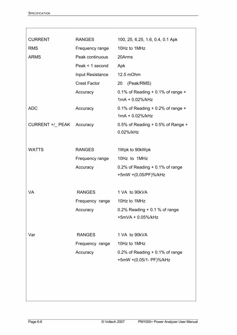
CURRENT RANGES 100, 25, 6.25, 1.6, 0.4, 0.1 Apk
RMS Frequency range 10Hz to 1MHz
ARMS Peak continuous 20Arms
Peak < 1 second Apk
Input Resistance 12.5 mOhm
Crest Factor 20 (Peak/RMS)
Accuracy 0.1% of Reading + 0.1% of range +
1mA + 0.02%/kHz
ADC Accuracy 0.1% of Reading + 0.2% of range +
1mA + 0.02%/kHz
CURRENT +/_ PEAK Accuracy 0.5% of Reading + 0.5% of Range +
0.02%/kHz
WATTS RANGES 1Wpk to 90kWpk
Frequency range 10Hz to 1MHz
Accuracy 0.2% of Reading + 0.1% of range
+5mW +(0.05/PF)%/kHz
VA RANGES 1 VA to 90kVA
Frequency range 10Hz to 1MHz
Accuracy 0.2% Reading + 0.1 % of range
+5mVA + 0.05%/kHz
Var RANGES 1 VA to 90kVA
Frequency range 10Hz to 1MHz
Accuracy 0.2% of Reading + 0.1% of range
+5mW +(0.05/1- PF)%/kHz
SPECIFICATION
PM1000+ Power Analyzer User Manual © Voltech 2007 Page 6-7
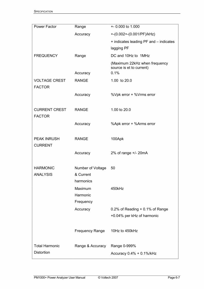
Power Factor Range +- 0.000 to 1.000
Accuracy +-(0.002+-(0.001/PF)/kHz)
+ indicates leading PF and indicates
lagging PF
FREQUENCY Range DC and 10Hz to 1MHz
(Maximum 22kHz when frequency source is et to current)
Accuracy 0.1%
VOLTAGE CREST
FACTOR
RANGE 1.00 to 20.0
Accuracy %Vpk error + %Vrms error
CURRENT CREST
FACTOR
RANGE 1.00 to 20.0
Accuracy %Apk error + %Arms error
PEAK INRUSH
CURRENT
RANGE 100Apk
Accuracy 2% of range +/- 20mA
HARMONIC
ANALYSIS
Number of Voltage
& Current
harmonics
50
Maximum
Harmonic
Frequency
450kHz
Accuracy 0.2% of Reading + 0.1% of Range
+0.04% per kHz of harmonic
Frequency Range 10Hz to 450kHz
Total Harmonic
Distortion
Range & Accuracy Range 0-999%
Accuracy 0.4% + 0.1%/kHz
SPECIFICATION
Page 6-8 © Voltech 2007 PM1000+ Power Analyzer User Manual
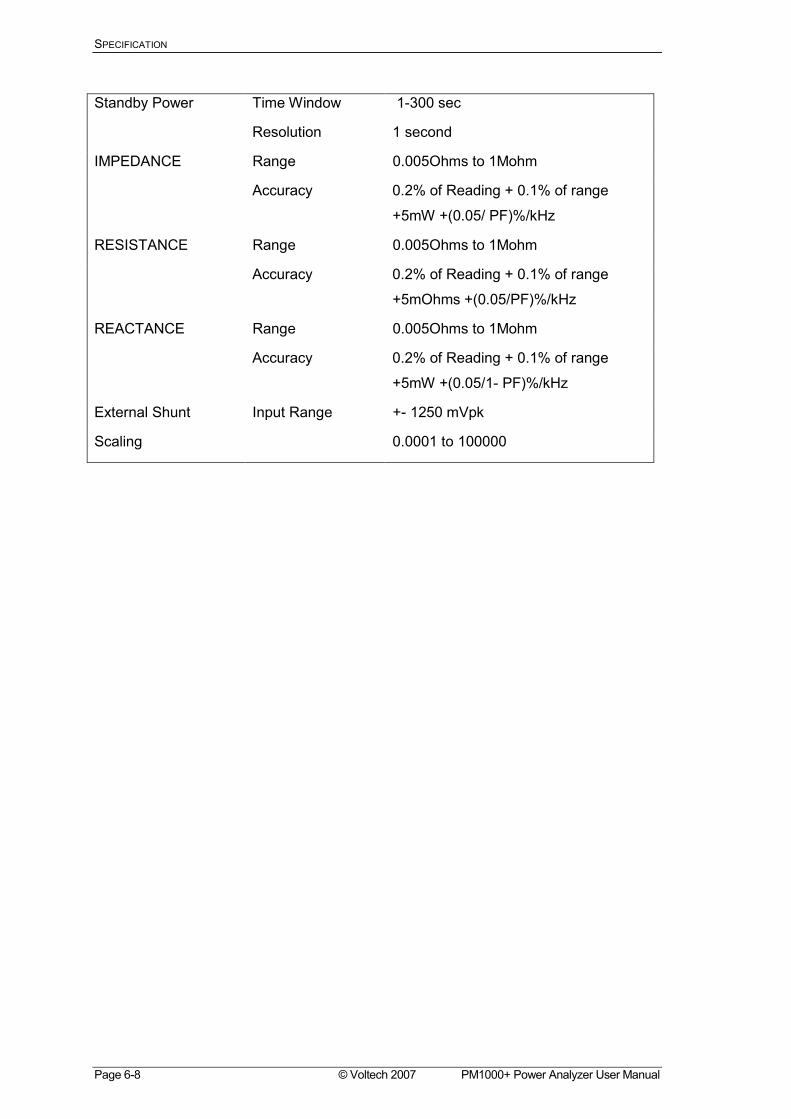
Standby Power Time Window 1-300 sec
Resolution 1 second
IMPEDANCE Range 0.005Ohms to 1Mohm
Accuracy 0.2% of Reading + 0.1% of range
+5mW +(0.05/ PF)%/kHz
RESISTANCE Range 0.005Ohms to 1Mohm
Accuracy 0.2% of Reading + 0.1% of range
+5mOhms +(0.05/PF)%/kHz
REACTANCE Range 0.005Ohms to 1Mohm
Accuracy 0.2% of Reading + 0.1% of range
+5mW +(0.05/1- PF)%/kHz
External Shunt Input Range +- 1250 mVpk
Scaling 0.0001 to 100000
WARRANTY, SERVICE AND UPDATES
PM1000+ Power Analyzer User Manual © Voltech 2007 Page 7-1
7. WARRANTY, SERVICE AND UPDATES 7.1. WARRANTY
The Voltech PM1000+ Power Analyzer is warranted against defects in materials and
workmanship for a period of twelve (12) months from the date of shipment.
In the event of failure of a customer unit during this period, Voltech will:
• At Voltechs discretion, repair or replace the faulty unit free-of-charge for a unit
returned to an authorized service center. Shipment from the customer address will
be the responsibility of the customer.
Voltech reserves the right to waive this benefit in any event where it is clear upon
inspection that the cause of the failure is due to customer misuse.
Voltech will be the sole arbiter in this circumstance.
• Pay all return shipment charges from the Voltech service center to the customer.
• Repair/verify the customer unit before dispatch. A certificate of verification will be
issued as a matter of course.
The PM1000+ is a complex product and may not be completely free of errors. You are
advised to verify your work. In no event will Voltech be liable for direct, indirect, special,
incidental or consequential damages arising out of the use of or inability to use the
PM1000+ or its accessories, even if advised of the possibility of such damage. In
particular, Voltech is not responsible for any lost profits or revenue, loss of use of
software, loss of data, cost of substitute products, claims by third parties, or for other
similar costs.
7.2. CALIBRATION AND SERVICE
To confirm the accuracy of your PM1000+ a calibration should be carried out every 12
months.
WARRANTY, SERVICE AND UPDATES
Page 7-2 © Voltech 2007 PM1000+ Power Analyzer User Manual
Verification is carried out using purpose-built equipment. The verification can be
performed by an authorized Voltech service center.
For details of verification facilities and any other service requests, please see the
service area of our website at www.voltech.com. Voltech strongly recommends that
you discuss your service requirements with your supplier before service is needed.
7.3. OBTAINING SERVICE AND APPLICATIONS SUPPORT
Please see the service and applications support centers on our website at
www.voltech.com.
7.4. UPDATING FIRMWARE
Regular firmware updates will be made available and maintenance updates are free of
charge for all users.
Please see the applications support center on our website at www.voltech.com

Warranty, Service and Updates
PM1000+ Power Analyzer User Manual © Voltech 2007 Page 7-3

SAFETY
PM1000+ Power Analyzer User Manual © Voltech 2007 Page 8-1
8. SAFETY INFORMATION 8.1. SAFETY FEATURES
The PM1000+ has been designed with safety features, such as shrouded safety
connectors, that provide the operator with a high level of protection against the risk of
electric shock. As with any dangerous equipment, however, it is important that an
assessment of the overall risk to safety is made during installation. It is the users
responsibility to ensure compliance with any local regulations that may be applicable to
the health and safety of operators
8.2. SAFETY INSTRUCTIONS
• The PM1000+ and its accessories have been constructed in compliance with the
requirements of EN61010-1, Pollution Degree 2, Installation Category II, FOR
INDOOR USE ONLY. This ensures the safety of the analyzer and the user when
normal precautions are followed
• WARNING: The analyzer MUST be earthed. The power source should be inserted
in a socket with a protective ground contact
• The power source should be inserted before connections are made to measuring or
control circuits
• Do not attempt to remove outer cover without first disconnecting auxiliary and test
power supply
• This instrument must only be serviced by qualified personnel who understand the
danger of shock hazards
• When the instrument is removed from its case hazardous voltages are present
• The electronic circuitry of this instrument is fully floating with respect to ground. If
the instrument is opened and dangerous voltages (above 50V peak) applied to the
input terminals then all the circuitry must be considered 'Live'
• The signal leads must be in good condition with no damage.
!
SAFETY
Page 8-2 © Voltech 2007 PM1000+ Power Analyzer User Manual
• Replace fuses only with the same type and rating as specified in this manual
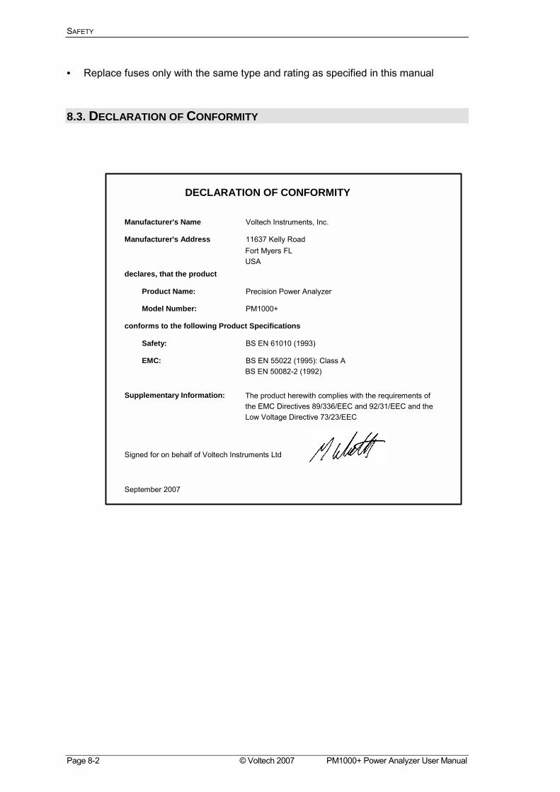
8.3. DECLARATION OF CONFORMITY
Manufacturer's Name
DECLARATION OF CONFORMITY
Voltech Instruments, Inc.
11637 Kelly RoadFort Myers FL USA
Signed for on behalf of Voltech Instruments Ltd
BS EN 61010 (1993)
The product herewith complies with the requirements of the EMC Directives 89/336/EEC and 92/31/EEC and the Low Voltage Directive 73/23/EEC
BS EN 55022 (1995): Class A BS EN 50082-2 (1992)
Manufacturer's Address
declares, that the product
Product Name:
Model Number:
conforms to the following Product Specifications
Safety:
EMC:
Supplementary Information:
September 2007
Precision Power Analyzer
PM1000+