pmod hex keypad on de1-soc - university of toronto
TRANSCRIPT
PMOD HEX Keypad on DE1-SoC Version 1.1 by Fred Aulich
The PMOD HEX keypad uses the GPIO protocol. For more information about this protocol and the PMOD
HEX Keypad got to the following link:
https://reference.digilentinc.com/reference/pmod/pmodkypd/reference-manual
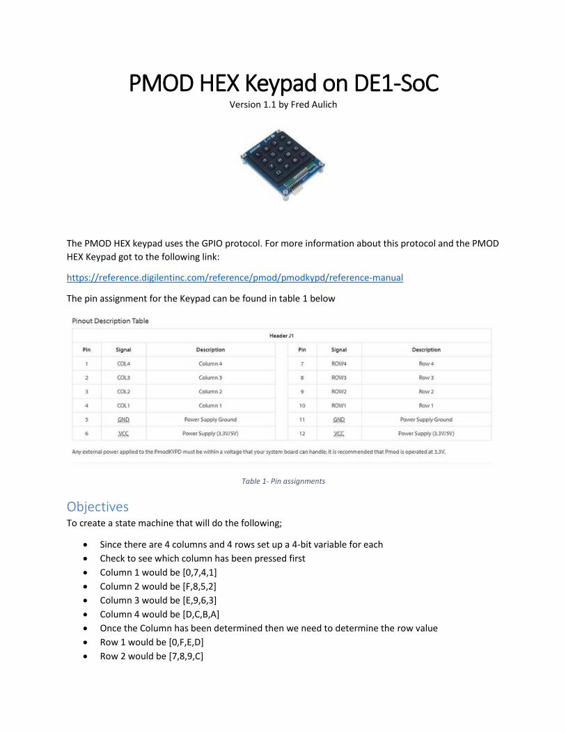
The pin assignment for the Keypad can be found in table 1 below
Table 1- Pin assignments
Objectives To create a state machine that will do the following;
Since there are 4 columns and 4 rows set up a 4-bit variable for each
Check to see which column has been pressed first
Column 1 would be [0,7,4,1]
Column 2 would be [F,8,5,2]
Column 3 would be [E,9,6,3]
Column 4 would be [D,C,B,A]
Once the Column has been determined then we need to determine the row value
Row 1 would be [0,F,E,D]
Row 2 would be [7,8,9,C]
Row 3 would be [4,5,6,B]
Row 4 would be [1,2,3A]
Once the key has been determined display the key value on one of the HEX displays of the DE1-
SOC
Create a clock to act as a counter for the state machine
Using one of the switches on the DE1-SoC, create a reset to make sure all the registers can be
set to start location and enable state machine
Use GPIO 2 to connect PMOD adaptor to DE1-SoC board
Use GPIO 1 on DE1-SoC and LEDS to visually indicate the state of row and column values
Now that we have this information we can start to create the state machine. A copy of the code can be
found on the DESL website at he following location:
http://www-ug.eecg.toronto.edu/msl/peripherals_test_code.html
Select HEX keypad interface. The file is a ZIP file. Download the ZIP file and open it on your pc. Using
Quartus version 18.0 or greater to compile the program. The program has a lot of comments to help
explain the code works.
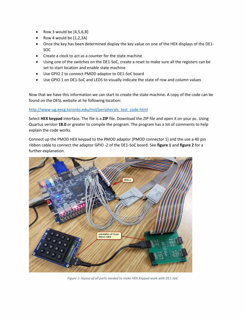
Connect up the PMOD HEX keypad to the PMOD adaptor [PMOD connector 1] and the use a 40 pin
ribbon cable to connect the adaptor GPIO -2 of the DE1-SoC board. See figure 1 and figure 2 for a
further explanation.
Figure 1- layout of all parts needed to make HEX Keypad work with DE1-SoC
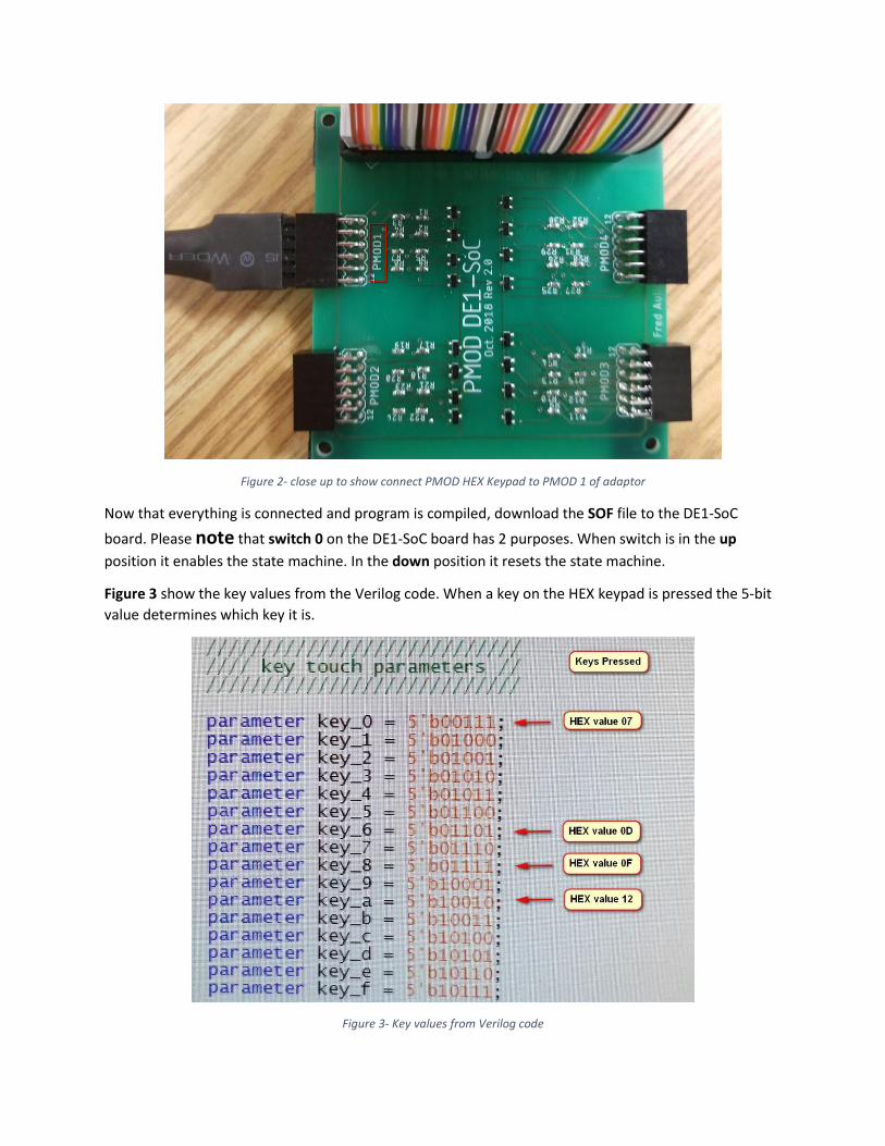
Figure 2- close up to show connect PMOD HEX Keypad to PMOD 1 of adaptor
Now that everything is connected and program is compiled, download the SOF file to the DE1-SoC
board. Please note that switch 0 on the DE1-SoC board has 2 purposes. When switch is in the up
position it enables the state machine. In the down position it resets the state machine.
Figure 3 show the key values from the Verilog code. When a key on the HEX keypad is pressed the 5-bit
value determines which key it is.
Figure 3- Key values from Verilog code

Figure 4 shows that when key 0 is pressed on the key pad, it displays 0 on the HEX display of the DE1-
S0C
Figure 4 - When Key 0 is pressed 0 appears on HEX display of DE1-SoC
Figure 5 to 8 shows the logic analyzer result when certain keys are pressed. The logic analyzer result was
done with the Keysight(Agilent) MSO-X-3024A.
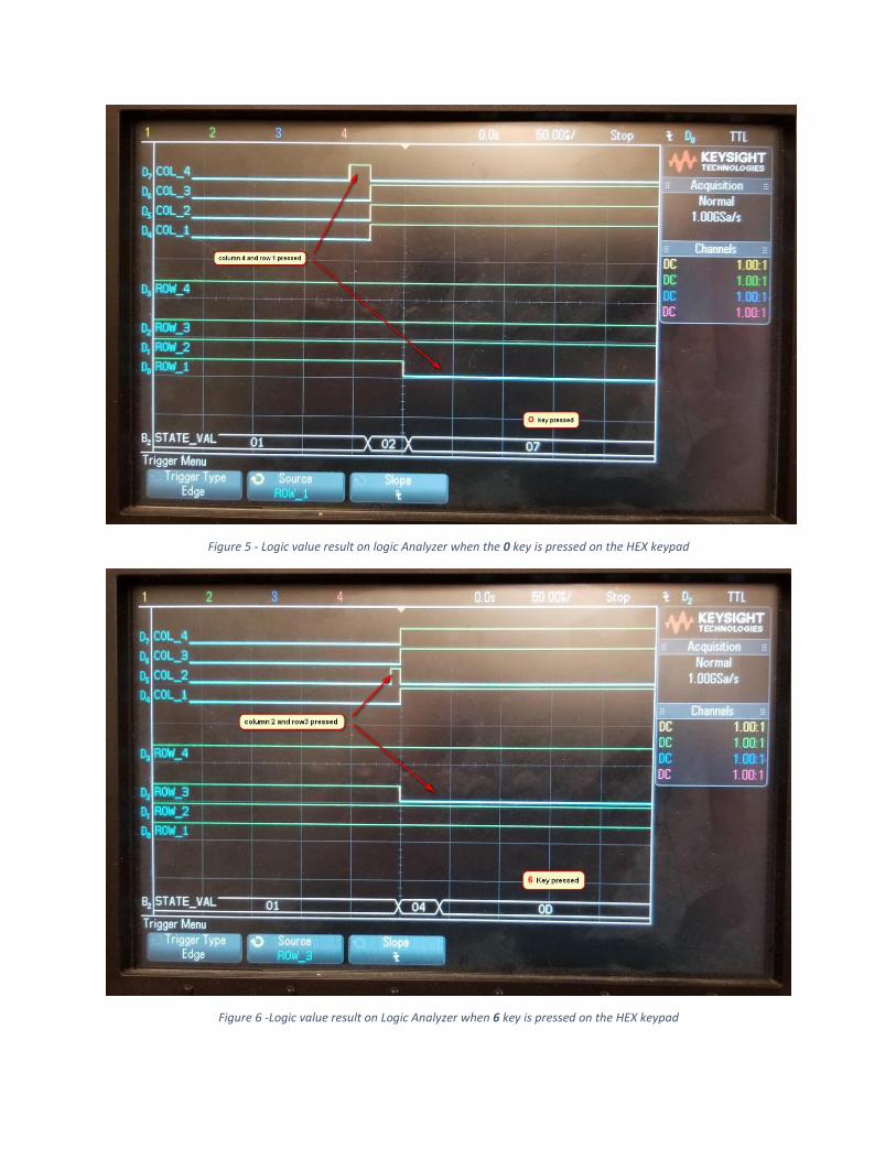
Figure 5 - Logic value result on logic Analyzer when the 0 key is pressed on the HEX keypad
Figure 6 -Logic value result on Logic Analyzer when 6 key is pressed on the HEX keypad

Figure 7- Logic value result on logic Analyzer when 8 key is pressed on the HEX keypad
Figure 8 -logic value result on logic analyzer when the A key is pressed on the HEX keypad

This is the end of the tutorial for the PMOD HEX keypad. The objective was to give you a general insight
on how to make the keypad work with the DE1-SoC board. For further information, ask the lab manager
for the DESL lab. His office is BA3104.