pnl-5722, 'operating experience & aging assessment of eccs ... · pnl-5722 technical...
TRANSCRIPT
PNL-5722
Technical Evaluation Report
Operating Experience andAging Assessment of ECCSPump Room Coolers
D. E. BlahnikR. L. Goodman
October 1986
Prepared forU. S. Nuclear Regulatory Commissionunder Contract DE-AC06-76RLO 1830NRC FIN B2865
Pacific Northwest LaboratoryOperated for the U.S. Department of Energyby Battelle Memorial Institute
z.~~~~~~w,
O-; , BatetlewPLEASE RETURN TO:A. B. JOHNSON, JR.PSL/1174/3000BNW
/ *i/

PNL-5722V..
TECHNICAL EVALUATION REPORT
OPERATING EXPERIENCE AND AGING ASSESSMENTOF ECCS PUMP ROOM COOLERS
Phase I Study
D. E. Blahnik.R. L. Goodman
October 1986
Prepared forOffice of Nuclear Regulatory ResearchU.S. Nuclear Regulatory Commissionunder Contract DE-AC06-76RL0 1830NRC FIN B2865
Pacific Northwest LaboratoryRichland, Washington 99352
-.-.:
.
,. ..
;"''-' ;-r ...:::
rat
o�.o.:
i.........:
,.
',...':' ''":
.
:w ,......,...
':"f,.:.
....''.,-. ::....,..-:
�r.:- :
:' '"
'....:,
w -:
'. :. . . .. . ~ ~ ~ ~ ~ ~ ~ ~ ~ ~ ~ ~ ~ ~ ~ ~ ~ . .. . a . 0W .. . M. W .

DISCLAIMER
This report was prepared as an account of work sponsored by an agency of theUnited States Government. Neither the United States Government nor any agencythereof, nor Battelle Memorial Institute, nor any of their employees, makes anywarranty, expressed or Implied, or assumes any legal liability or responsibility forthe accuracy, completeness, or usefulness of any information, apparatus, product,or process disclosed, or represents that its use would not infringe privately ownedrights. Reference herein to any specific commercial product, process, or service bytrade name, trademark, manufacturer, or otherwise, does not necessarily consti-tute or imply its endorsement, recommendation, or favoring by the United StatesGovernment of any agency thereof, or Battelle Memorial Institute. The views andopinions of authors expressed herein do not necessarly state or reflect those of theUnited States Government or any agency thereof, or Battelle Memorial Institute.
PACIFIC NORTHWEST LABORATORYoperated by
BATTELLEfor the
UNITED STATES DEPARTMENT OF ENERGYunder Contract DE-AC06-76RLO 1830

ABSTRACT
This report provides a preliminary aging assessment of safety-relatedroom coolers for the emergency core cooling system (ECCS) pump rooms in nuclearplants. The assessment conforms to the NRC Nuclear Plant Aging Research (NPAR)Program strategy. The assessment is based on limited information obtainedthrough public and private data bases, equipment vendors, utility contacts,literature searches, and expert opinion.
The ECCS pump room cooler system description was determined by review ofFSARs and vendor supplied information. Data from LERs, review of maintenancerequests at a reactor plant, and discussions with personnel that have utilitymaintenance experience were used to determine the operating experience of pumproom coolers. Failure modes, causes, frequency rates, and methods of detectionare summarized from the operating experience. Maintenance actions and modifi-cations needed as a result of the operator experience are addressed to theextent that information was available. Operational stressors are summarized,manufacturer recommendations for maintenance and surveillance are listed, andaging and service-wear monitoring are briefly evaluated.
* iii

ACKNOWLEDGMENTS
The authors appreciated the support of the NRC Nuclear Plant AgingResearch Program manager, Jit Vora, in implementing and completing this study.The help of A. B. Johnson, Jr., the PNL project manager, was also instrumentalin completing the study.
A number of individuals assisted in collecting data, providing experiencedopinions, making assessments and preparing and reviewing the report. Theassistance was appreciated from the following individuals: *Mano Subudhi,Brookhaven National Laboratory; George Murphy and Ray Borkowski, Oak RidgeNational Laboratory, James Cleveland, SEA Consultants, Inc.; Dennis Pawlak,Ellis and Watts; Hunter McCluer and Mike Kippes, WPPSS; and John Vause, RobertGruel, and Ben Johnson of Pacific Northwest Laboratory.
The assistance of David Hillard for editing and Lila Valdez and Pat Youngfor typing the report is also gratefully acknowledged.
v

EXECUTIVE SUMMARY
Pacific Northwest Laboratory conducted this review of pump room cooleroperating experience under the U.S. Nuclear Regulatory Commission's NuclearPlant Aging Research Program. The purpose of Phase I of this study is to makean interim aging assessment of emergency core cooling system (ECCS) pump roomcoolers based on actual operating experience data.
The ECCS pump room coolers prevent excessive temperatures in the roomwhere the ECCS pumps are operating. The ECCS pumps are used in nuclear plantsto provide reactor core cooling and primary coolant inventory makeup duringemergencies such as a LOCA. The ECCS pumps and pump room coolers are bothimportant safety-related equipment.
Pump room coolers were selected for the aging assessment because of safetyconcerns associated with the failure of a pump room cooler to perform itsdesignated function. This study was performed to determine whether aging andservice-wear effects substantially reduce safety margins for room cooling.
The equipment boundary selected for examination in this study is definedas the room cooler system components within the fan/coil enclosure. Most roomcoolers are quite similar within this boundary. Because elevated temperaturesand humidities may occur in the pump rooms, electrical components within theboundary are usually limited to the drive motor and thermostats. The inter-facing motor controls and other electrical and electronic components arelocated in the central motor control centers, where environmental conditionsare more closely controlled. The water supply for the cooling coils and thepumps and valves that control the water flow are usually located in otherareas.
Room cooler operating experience data obtained during this study suggestthat pump room cooler operation has been relatively trouble-free. Room coolerfan motors are subject to more stressors than any other major component, butavailable data indicate that failure rates have been low. Not unexpectedly,the v-belts, a minor component, fail most frequently and cause the mostmaintenance problems.
Vibration is the largest cause of rapid aging in room coolers. The v-beltfan drives seem to be more prone to cause vibration than direct fan drives, butdata are insufficient to substantiate this.
Licensee event report (LER) data indicate that room cooler failures arerare. Room cooler failures often develop outside the room cooler boundary inthe motor control center electrical components or in the service water systemchiller, valves, or pumps. These components are subjects of aging assessmentsin other NPAR Program tasks, and therefore no duplication of effort is beingmade. Motors are also being assessed in a separate task.
The lack of available data made it difficult to base the interim agingassessment of ECCS pump room coolers on operating experience. Part of the
vii

reason for this lack of data is that ECCS pump room coolers were not incor-porated into early plant designs. An increasing number of the plants that havecome on line since 1972 have room coolers. Most plants coming on line in thenear future will incorporate ECCS pump room coolers. Limited operating experi-ence and largely trouble-free operation have resulted in a relatively smalldata base relating to room cooler service history.
Interim recommendations for minimizing the rate of room cooler aging areto follow manufacturer recommendations for maintenance and to monitor vibra-tion, temperature, and sound, where practical. It is recommended that theaging, wear, and performance of pumps, valves, service water chiller, and othercomponents associated with room cooler systems be investigated by the existingNPAR tasks to which the components are related. It is further recommended thatPhase II of the ECCS pump room cooler aging assessment be delayed until NPARsystems assessments now underway have further addressed the significance ofroom coolers and more extensive operating experience is available.
viii

CONTENTS
ABSTRACT ............................ *.*.*.*...........****.*..*......*.. iii
ACKNOWLEDGMENTS ....................... * * * * * * * .......... .....* v
EXECUTIVE SUMMARY .......... *** ********* ********...... vii
ACRONYMS AND ABBREVIATIONS ................... .. .................. ..... xiii
1.0 INTRODUCTION ....................... *...*.*..*. ************** *** 1.1
2.0 PUMP ROOM COOLER SYSTEM DESCRIPTION ......... ..................... 2.1
2.1 ROOM COOLER DESIGN .... ..................................o........... 2.3
2.2 ROOM COOLER DESIGN SPECIFICATIONS ............ ................ 2.5
2.3 PRINCIPAL TYPES AND USES OF ROOM COOLERS IN BWRS AND PWRS ... 2.8
2.4 EQUIPMENT BOUNDARY ......................... .. ....... 2.11
2.5 FUNCTIONAL REQUIREMENTS ............ o.......................... 2.11
3.0 DATA SOURCES FOR PUMP ROOM COOLER OPERATING EXPERIENCE ........... 3.1
3.1 LICENSEE EVENT REPORTS (LERs) ......................... o.....o. 3.1
3.2 IN-PLANT RELIABILITY DATA SYSTEM (IPRDS) ..................... 3.1
3.3 NUCLEAR POWER EXPERIENCE (NPE) .............................. 3.2
3.4 VENDOR SURVEY ..................... ....... 3.2
3.5 UTILITY CONTACTS ............................................ 3,2
3.6 PUBLISHED REPORTS ........................................... 3.2
3.7 ONGOING RESEARCH .. o ......... 3.2
3.8 EXPERT OPINION ....................................... 3.2
4.0 TESTING ........................ .................................. 4.1
5.0 OPERATING EXPERIENCE ..................... ; ....... 5.1
5.1 FAILURE MODES AND CAUSES .................... o................. 5.1
5.2 FREQUENCY OF FAILURES ....... o ................. ..... ; 5.4-
ix

5.3 METHODS OF DETECTION ........................
5.4 MAINTENANCE ACTIONS .........
5.5 MODIFICATIONS RESULTING FROM FAILURES .......................
6.0 SUMMARY OF OPERATIONAL STRESSORS .....................
6.1 MECHANICAL STRESSORS ................................
6.1.1 Fan Motor ............................................
6.1.2 Coupling .............................................
6.1.3 V-Belts and Sheaves ..................................
6.1.4 Fan ..................................................
6.1.5 Cooling Coil .........................................
6.1.6 Housing ..............................................
6.2 THERMAL STRESSORS .......................................
6.2.1 Fan Motor ............................................
6.2.2 V-Belts ........... ..........................
6.2.3 Fan ..................................................
6.3 ENVIRONMENTAL STRESSORS ......................................
6.3.1 Fan Motor ............................................
6.3.2 V-Belts ..............................................
6.3.3 Fan ...................................
6.3.4 Cooling Coil .............................
6.4 ELECTRICAL STRESSORS
6.4.1 Fan Motor ................................
6.5 RADIATION STRESSORS ........................
6.5.1 Fan Motor .............................................
6.6 CHEMICAL STRESSORS ..........................................
6.6.1 Fan Motor ............................................
5.4
5.5
5.5
6.1
6.1
6.1
6.1
6.1
6.3
6.3
6.3
6.3
6.4
6.4
6.4
6.4
6.4
6.5
6.5
6.5 [6.56.5 i6.5 i.
6.6
6.6
6.6
6.6
x

6.6.2 Motor and Fan Bearings ...............................
6.6.3 Cooling Coil .........................................
6.7 PRINCIPAL VIBRATION CAUSES IN ROOM COOLERS
7.0 MANUFACTURERS RECOMMENDATIONS FOR MAINTENANCE AND SURVEILLANCE
8.0 AGING AND SERVICE-WEAR MONITORING AND ASSESSMENT ................
9.0 EXPERT OPINION ..............
).0 CONCLUSIONS AND RECOMMENDATIONS .............
10.1 RECOMMENDATIONS ....................................
10.2 FUTURE WORK ..............................
1.0 REFERENCES ............
PPENDIX A - GENERAL BEHAVIOR OF AIR-COOLED EQUIPMENT
PPENDIX B - LIST OF FSARs/PSARs REVIEWED ........
6.6
6.6
6.7
7.1
8.1
9.1
10.1
10.2
10.2
11.1
A.1
B.1
4.
4-
I-C:.
I
'1.
[
xi

FIGURES
1.1 NPAR Program Strategy ... ....................................... 1.2
2.1 ECCS Pump Room Cooler Functional Design .......................... 2.2
2.2 ECCS Pump Room Cooler ............................................ 2.5
2.3 ECCS Pump Room Cooler Layout .................. ......... * 2.6
2.4 Examples of Building Ventilation and Room Cooler Concepts .... .... 2.9
2.5 Components Located Inside and Outside the ECCS Pump RoomCooler Boundary .................................................. 2.12
5.1 ECCS Pump Room Cooler LER Review Summary ......................... 5.2
TABLES
2.1 Typical Materials Used in Component Construction ................. 2.4
6.1 Primary Stressors and Aging Mechanisms--Areas of Concern Withinthe Room Cooler Boundary ......................................... 6.2
xii
. .. .. I . ......... 1_7 ..... . . . . .. - . . ; - - --: ... : .7. �' ,. .:, . . .. . .. . . .. . .-. .- - .7�T --
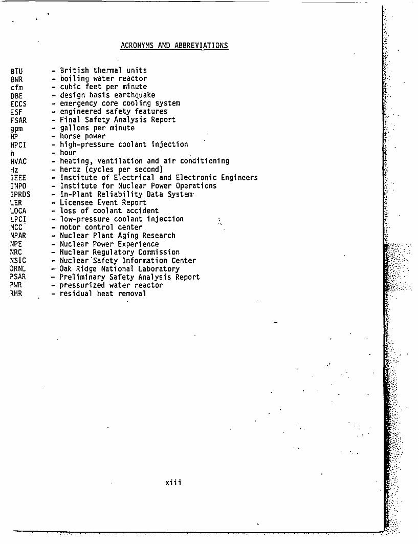
ACRONYMS AND ABBREVIATIONS
BTU - British thermal unitsBWR - boiling water reactorcfm - cubic feet per minuteDBE - design basis earthquakeECCS - emergency core cooling systemESF - engineered safety featuresFSAR - Final Safety Analysis Reportgpm - gallons per minuteHP - horse powerHPCI - high-pressure coolant injectionh - hourHVAC - heating, ventilation and air conditioningHz hertz (cycles per second)IEEE - Institute of Electrical and Electronic EngineersINPO - Institute for Nuclear Power OperationsIPRDS - In-Plant Reliability Data SystemLER - Licensee Event ReportLOCA - loss of coolant accidentLPCI - low-pressure coolant injectionMCC - motor control centerNPAR - Nuclear Plant Aging ResearchNPE - Nuclear Power ExperienceNRC - Nuclear Regulatory CommissionNSIC - Nuclear'Safety Information CenterJRNL - Oak Ridge National LaboratoryPSAR - Preliminary Safety Analysis ReportPWR - pressurized water reactor1HR - residual heat removal
xi.
xiii~~~~~~~~~ .'.

1.0 INTRODUCTION
Emergency core cooling system (ECCS) pumps are used in nuclear plants toovide reactor core cooling and primary coolant inventory makeup during emer-ncies such as a loss-of-cooling accident. Pump room coolers are often usedmaintain room ambient air temperatures within acceptable limits for the pump
tors. The coolers and their related heat exchanger systems also greatlyduce the building heat accumulation and minimize the amount of air that mustexhausted to the environment through filtered systems.
The Nuclear Plant Aging Research (NPAR) Program selected ECCS pump roomolers for an aging assessment because of safety concerns associated with theilure of coolers to perform their designated function (Davis et al. 1985).e present study was performed to determine whether aging and service-wearfects substantially reduce safety margins for room cooling. Phase I makes anterim assessment based on actual operating experience.
Pacific Northwest Laboratory (PNL) performed this study for the Nucleargulatory Commission (NRC) Office of Research, Division of Engineering Tech-logy, Electrical Engineering Branch as part of the NPAR Program. The NRCtablished the NPAR Program .as a comprehensive research program to resolvesues related to the impact of aging and service wear of equipment and systemsplant safety at commercial reactor facilities (US NRC 1985). The NPAR goals
garding component and system aging are:
* to identify and characterize aging and service-wear effects that, ifunchecked, could cause degradation of structures, components, andsystems and thereby impair plant safety
* to identify methods of inspection, surveillance, and monitoring--orof evaluating residual life--of structures, components, and systemsthat will ensure timely detection of significant aging effects priorto loss of safety function
* to evaluate the effectiveness of storage, maintenance, repair, andreplacement practices in mitigating the effects of aging and dimin-ishing the rate and extent of degradation caused by aging and servicewear.
I
6
e" ''A-.: .:c .- :
L';.':........
A:, .....
.
..
..
: '
,'.''.. .:
..,-
..:.,
:.....I,...
..
I'.... .
':
:
*..',..
, accomplish these-goals, the NPAR program strategy illustrated in Figure 1.1being followed. The major program steps/deliverables are shown in circles,
'd the work activities required to accomplish these activities are provided in:e boxes. The Phase I steps covered in this study-are indicated by cross-itching in the applicable circles and boxes.
This report contains a description of pump room cooler systems, an:planation of sources for operating experience data, a listing of typical!sting procedures, an analysis of operating experience, and a summary of
1.1
:, . . . . ..

operational stressors. These sections are followed by sections on manufacturerrecommendations for maintenance and surveillance, aging and service-wearmonitoring and assessment, expert opinion, and conclusions and recommendations.
1.2

Considerationsfor
IP US. NPROS. Es.IInteractions EntensionsNPE. etc. EPractical. Colt Interactions Value/ with Code
Experts' National Standards Effective with Impact andKrnowtedge \ and Inspection Performance Industry Study Standards
es Indicators Committees
AcceptacGuidetia
Maintennc
Define > \ opefednet \ \ v Aging Chafeeretisation 4 Asessment and | t GuideiinGuideeine
forService LifePredictions
Equipm~oef~nt of \ EXP~tlS \ \Analrsis ol \ nte*im Aeent Comprehensive Aging Apptlicaton
Studnr l :\Knowtedge Operating Aging Charssctsion Asement and Guideftin |
Aging Pra cti e parae ten s M ntenance Analyses totl > Ongoing 'Artificial Accelerated\ I I I I MM
: < Phase I ' | i Phase on
.~~~~~~~~~~~~~~~~~~~~~~~~~~~~~~~~~~~~~~~~~~~~~~~~~~~~~~~~~~~~~~~~~~~~~~~~~~~~~~~~~~~~~~~~~~~~~~~~~~~~~~~~
FIGURE 1.1. NPAR Program Strategy
.~~~~ .. ~ .'** ~ ~ ~¼ , . . . I
~~~~~~~~~~~. ., . . I
. ' ' . 'c.
;~~~~~~~~~~~~~~~~~~~~a d: Se cRisk ~ ~ ~ ~ ~ ~ ~~: Inusr Opeatins Suvilne : o.Tss'n"dace A t
..arl nonc Metod

2.0 PUMP ROOM COOLER SYSTEM DESCRIPTION
Older nuclear plants (15 to 25 years) do not have ECCS pump room coolers.Some intermediate-aged plants (5 to 15 yeas old) have room cooler systems,while others do not. New plants (O - 5 years old) for all four of the U.S.reactor suppliers have pump room coolers with large cooling capacities tohandle the higher power capacities of the newer reactors.
Designs for pump room cooling systems vary greatly among plants. Coolersare often interlocked with pumps and operate only when the pumps operate. Somecoolers operate only during a loss-of-cooling while others are left on continu-ously. Other coolers operate only when room temperatures exceed the thermostathigh setpoint.
The ECCS pump roum coolers prevent excessive temperatures in the roomwhere the ECCS pumps are operating. The ECCS pumps are used in nuclear plantsto provide reactor core cooling and primary coolant inventory makeup duringemergencies such as a LOCA. The ECCS pumps and pump room coolers are bothimportant safety-related equipment.
The ECCS pump room coolers are basically safety-related fan coil unitscomprised of a steel housing containing an inlet opening, finned cooling coils,a fan-motor unit, and an outlet opening (Figure 2.1). Sometimes air inlets andoutlets have louvers that can be adjusted to distribute and control air flow.Sometimes filters are placed in the inlet side.
i; The ECCS pump room cooling system includes the pump room cooler unititself, plus a coolant supply system, motor control center and power supply,and other items, such as a room thermostat, manual switch, drain, and venti-
,. lation dampers.
ECCS room coolers are located in individual rooms housing the followingtypes of ECCS pumps:* high-pressure safety injection, charging, and core spray pumps.* intermediate-pressure safety injection pumps.* low-pressure safety injection and core spray pumps.* residual or decay heat removal, pumps.* containment spray pumps.
Pump names vary with the vintage and supplier of the individual plants. TheECCS pumps--sometimes called engineered safety feature (ESF) pumps--are safety-related equipment that perform an important function during a LOCA. The vari-ous ECCS pumps provide the primary cooling water system with high-pressurewater injection for small-break LOCAs, low-pressure (high flow rate) waterinjection for large-break LOCAs, and long term core cooling once the reactor isdepressurized and stable. The containment spray function also helps to depres-surize and cool the containment and mitigate the spread of contamination. TheECCS pumps sometimes serve multiple purposes and need to function in normaloperating and shutdown situations as well as emergency situations.
.2.1

Drive Motor*(230/460 Volt AC.Power From Motor Control Center*and Emergency Diesel Generator*Backup)
Louvers (Optional)
Belt Driven orDirect DriveFans
Screen andFilters (if used)
Coil Inlet-Service Watel*(Closed Loop orRiver, Ocean, Lake)
Air Flow Af
_ Fan Unit(Centrifugal orVaneaxial)
Fins (Copper orAluminum)
_ PlenumZone
CondensateDrain
Coil Section(Copper or Copper-Nickle Tubes w/Fins)
FIGURE 2.1. ECCS;Pump Room Cooler Functional Design. Components indicated) are being evaluated elsewhere in the NPAR program.D. k
The room 'coolers protect the pumps from excessive ambient room tempera-tures, which are detrimental to the pump life. The room coolers usually meetSeismic Category I and Safety Class 3 requirements, which ensure that roomcoolers remain functional during and after a reactor shutdown on account of anearthquake. The room coolers are usually in redundant pump trains so that lossof a room cooler, although it may disable one train, will not jeopardize emer-gency operations. Room coolers are also usually on the emergency diesel gene-rator safety busses so that they can operate during losses of offsite power.
2.2
T

I :
! only thing common among pump room cooling systems from plant to plant is3t they recirculate and cool the air within a given room. However, the:ual room cooler units within a given plant are often of the same or verynilar design and may be manufactured by a common vendor.
The rooms are normally heated and ventilated by the building central sys-n. The ventilation system helps to keep the room cool and prevent excessivenidity buildup. During a radiation release in the room, either the central)m air exhaust is diverted to a central filtered exhaust system or the con-ninated room is isolated from the central air flow by closing room dampers.
The ECCS pump rooms are usually located outside of the primary containmentea. They are usually located in the secondary containment of BWR buildingsin the auxiliary building of PWRs. The pump rooms are usually located ina basements of buildings, so they are sometimes subject to cool, dampvironments created by sumps, condensation, etc. One plant reported thateam leaks were also of concern.
1 ROOM COOLER DESIGN
A typical pump room cooler is shown in Figure 2.1. Warm air flows in ate bottom left through a screen and medium density filter (if one is used).xt, the air passes through the cooling coils, where it is cooled. It contin-s through a plenum zone into a fan. The electric motor-driven fan moves theoled air into a short duct and returns it to the room through the outlet.metimes louvers are placed on the outlet to direct the air flow towards theCS pump and piping.
Filters are optional, although they are usually installed for at least thenstruction stage to protect internal components from dust and other debris.dium efficiency filters are sometimes used to protect the surface of the coilom dust and dirt when the room cooler is operating.
The cooling coil water is supplied either from a river, lake, ocean, orrough a recirculating closed loop system. In southern states, the closedop system uses a refrigerated chiller to remove the heat. In some cases, theter flow through the coil is left on continuously. In other cases, it comesonly when the ECCS pump comes on or the fan is manually started. Vents andains are placed in the coil headers to provide a completely drainable, self-!nting coil. Drain pans are located below the coils to drain away the conden-.te water that results from the air cooling process. The power for the fanitor is supplied from a motor control center located in a separate air-rnditioned room. Backup power is available from a safety-related emergencyesel generator bus (same supply as for the ECCS pump it cools) when there isloss of offsite power.
Typical materials used in construction of the components are summarized inible 2.1. The cooling coils are finned to improve cooling efficiency. The)Als are usually made of seamless copper or copper-nickel tubing. The finiterial is aluminum, copper, or 90/10 copper-nickel. The coil casing is
2.3
I.I..
I.....
- ---------------------------------------------- -

TABLE 2.1. Typical Materials Used in Component Construction
Component
Motor Stator
Motor Rotor
Materials
Copper, Steel, Silicon'Steel, Aluminum,-Insulating Materials
Copper, Steel, Insulating Materials
Motor Accessories
Motor and Fan Bearings
Fan
Steel, Cast Iron, Brass, Copper, Seals and Gaskets,Mica, Plastics, Cable, Insulating Material, Graphite
Steel, Brass, Bronze, Grease, Lube Oil
Galvanized, Carbon and Stainless Steel; Aluminum
Cooling Coil
Room Cooler Housing
Sheaves, Pulleys
V-Belts
Tubes--Copper and Copper-NickelHeaders--Copper and Copper-NickelFins--Aluminum, Copper, and Copper-NickelCasing--Galvanized and Stainless Steel, Cast IronInlet/Outlet Connectors--Steel
Galvanized, Carbon, and Stainless Steel
Steel
Cord (cotton, rayon, synthetic, steel) Fabric, Rubber
usually constructed of stainless steel, cast iron, or galvanized steel.Headers are made of drawn copper or copper-nickel. They are brazed to thetubes, or the tubes are hydraulically expanded into die-formed collars in thefins. Lap joint steel stubs and flanges are used for the coil water supply andreturn connections.
The fan unit is usually either a centrifugal or vaneaxial type design.The fan is often constructed of galvanized or painted carbon steel. Fan bladesare often constructed of aluminum or stainless steel. The fan bearings arestandard anti-friction or sleeve types. The anti-friction type is availablewith either ball or roller bearings.
The fan is driven by a motor which is either directly coupled or indi-rectly coupled via a v-belt drive with sheaves. The fan is typically driven bya 60 Hz 3-phase horizontal induction-type motor. An excellent description ofthis motor is contained in a report, generated under the NPAR program, thatsummarizes aging characteristics of motors (Subudhi et al. 1985).
The room cooler air outlet may have a short section of duct or no duct atall. Small ducts or louvers can direct the cool air across the pump andrelated pipework.
2.4

i.
1'...
The frame and housing cover for the room cooler are usually constructed ofepoxy-coated carbon steel or galvanized steel, but stainless steel is usedoccasionally.
A photograph of a pump room cooler is provided-by Figure 2.2. An exampleof room cooler layout is provided in Figure 2.3. The capacity of the unitshown is about 720,000 BTU/h based on a 29,000 cfm airflow and a 96 gpm coolantwater flow rate. The centrifugal type fan is v-belt driven by a 20 HP motor.
2.2 ROOM COOLER DESIGN SPECIFICATIONS
The testing requirements for the room ECCS pump cooler and related systemsare identified in U.S. NRC Regulatory Guide 1.68 in the category of heating,cooling, and ventilation systems that serve spaces housing engineering safetyfeatures. The room coolers are part of the systems reviewed in the StandardReview Plan, NUREG-0800, under Section 9.4.5 (Engineers Safety Feature Venti-lation System). Room coolers are generally built to meet the quality assurancerequirements of 10 CFR 50 Appendix B or ANSI N 45.2. The design codes andstandards used for the room cooler components are listed below:
II
FIGURE 2.2. ECCS Pump Room Cooler (as supplied by Ellis and Watts)
2.5

"US" Upblast
900 Rotating CowlWith Double Deflecting
GrillsI-.. Il
-/ f
.am
R.H. Coil Conn.Outlet 2 1/2" M.P.T.
-SectionalizedHousing
R.H. Coil Conn.Inlet 2 1/2" M.P.T.
3/4' Dia. Mtg. Holes{for 1/2" Dia. Bolts)t
- - -7.
Front Grounding Pad Wlue
(2) PlacesCopper Plated Steel
FIGURE 2.3. ECCS Pump Room Cooler Layout (as supplied by Ellis and Watts)
... ... ---------

ans
Air Moving and Conditioning Association (AMCA)
* AMCA, Publication 99, Standards Handbook
* AMCA, Publication 201, Fan Application Manual: Fans and Systems
* AMCA, Standard 210, Laboratory Methods of Testing Fans for RatingPurposes
* AMCA, Publication 211, Certified Ratings Program Air-Performance
* AMCA Standard 300, Test Code for Sound Rating
* AMCA, Standard 500, Test Method for Louvers, Dampers and Shutters
Anti-Friction Bearing Manufacturers (AFBMA)
* ANSI/AFBMA, Standard 11, Load Ratings and Fatigue Life for RollerBearings
* ANSI/AFBMA, Standard 9, Load Ratings and Fatigue Life for BallBearings
an Motors
National Electric Manufacturers Association (NEMA MG-1)
Institute of Electrical and Electronic Engineers (IEEE)
* IEEE Standard for Qualifying Class 1E(a) Equipment for NuclearPower Generating Stations (IEEE-323)
* IEEE Recommended Practices for Seismic Qualification of Class 1EEquipment for Nuclear Power Generating Stations (IEEE-344)
soling Coils
Air-Conditioning and Refrigeration Institute (ARI 410 Standard for Forced-Circulation Air-Cooling and Air-Heating Coils)
American Society of Mechanical Engineers(ASME Section III, Class 2 or 3, "N" stamped)
i) Class lE - electrical equipment and systems that are essential foremergency reactor shutdown, containment isolation, reactor core cooling,etc. to prevent release of radioactive material into the environment,
2.7

2.3 PRINCIPAL TYPES AND USES OF ROOM COOLERS IN BWRS AND PWRS
Final Safety Analysis Reports (FSARs) and Preliminary Safety AnalysisReports (PSARs) for 49 U.S. nuclear power plants were reviewed to determine thtypes of ECCS pump room coolers and the extent of their use. The FSAR/PSARChapter 9.0, "Heating, Air Conditioning and Ventilation," was reviewed (SeeAppendix B).
Information gathered from the FSAR/PSARs indicates that pump room coolersystem designs are plant-specific. Early nuclear plants do not have pump roomper se, but large rooms that contain an entire train of each of the types ofECCS pumps. During a LOCA, all ventilation from nonessential areas in thebuilding is forced through the ECCS pump area for cooling purposes. The evolution of ventilation and the pump room coolers is illustrated in Figure 2.4.Only a few of the ventilation room cooler schemes in use are illustrated.
In early plants, ventilation air is concentrated in the ECCS pump area ifa LOCA occurs. Later plants used schemes with pump room coolers (shown in Concepts B and C). In Concept B, ventilation continues even during a LOCA. InConcept C, the rooms can be isolated during a LOCA, with the pump room coolerperforming all of the cooling.
The coolers are often interlocked with the ECCS pumps and operate onlywhen the pumps operate. Some coolers operate only during a LOCA or otheremergency. Others operate when the reactors are in operating, transient, andshutdown modes. Some are left on continuously. Others have the provision formanual operation to enable maintenance workers to work at lower temperatures.Some operate strictly by thermostat. Others operate by a combination of thesemodes.
Sometimes a cooler is in a separate room or cubicle with an individualpump. Other coolers serve more than one pumping system in a room or area. Th,pump rooms are usually separated by a heavy wall to assure that a redundantpump train will not be affected by a local debilitating situation.
ECCS pump room cooler maximum airflow rates range between 1,600 and30,000 cfm, and maximum heat removal rates range between 50,000 and800,000 BTU/h. The cooling water flow rate for coolers varies between 15 and100 gpm. The newer plants have the larger capacity cooler systems. The coolesystems are designed to keep maximum pump room temperatures below 104 to 1500F(the maximum temperature varies from plant to plant but is usually in the104 to 1200F range) after shutdown or isolation of other building ventilationand cooling systems. In a particular plant, the capacities and designs may benearly identical for the different pump rooms (e.g., HPCS, LPCS, RHR, CS).Other plants have a broader range of cooler sizes and designs.
Sometimes, if the room is large and has additional equipment, the coolershave ductwork to the different equipment locations. In other cases there is nductwork. If cooling is needed close to the pump, an outlet duct and/orlouvers are focused on the pump and piping.
2.8

2000CFM
2000CFM
2000CFM
I
2000CFM
l
2000CFM
2000CFM
2000CFM
2000CFM
Non- Non-ECCS ECCS
ECSS Non-Pumps ECCS
Non- Non-ECCS ECCS-
-1--_
-1 2000CFM
_* 2000CFM
2000CFM
12.000CFM 4
2000 -
CFM
+ ~~~~~~~~~~~~I. + I
ECCSPumps
4-- -
I t I t .2000 2000CFM CFM
LOCA Operation
_ 2000CFM
2000CFM
2000* CFM
2000CFM
Normal Operation
Concept A. Early Plant-Ventilation Only, Without PumpRoom Coolers
Typical Dampera,HPSI
Pump
FilteredExhaust
Concept B. Later Plants - ContinuousVentilation (Supply andExhaust Fans May Be TurnedOff During LOCA). With PumpRoom Coolers
Concept C. Later Plants - Room IsolationFrom Ventilation During LOCA,With Pump Room Coolers
FIGURE 2.4. Examples of Building Ventilation and Room Cooler Concepts..(R. C. indicates room cooler).
2.9

The FSAR/PSAR review covered a wide spectrum of plant ages, sizes, andreactor suppliers (See Appendix B). The designs, layouts, and nomenclatureroom coolers vary from plant to plant. A total of 49 plants were reviewed,some were multiple reactor units at a single site. Plant age ranged from ththat came on line as early as 1968 to some that recently went into commerciaoperation or may soon be going into operation. Plant sizes ranged from 4701250 MWe. Plants designed by all four U.S. reactor suppliers were reviewed.
The review indicated that 26 of the 49 plants have ECCS pump room cooleIt is uncertain how many of the remaining 23 plants have them. One plant,which has a central cooling system for its pump rooms, did not have pump roocoolers. Some of the plants that had pump room coolers also had central venlating sources. Appendix B summarizes by reactor vendor the plants that werreviewed.
The newer plants all have pump room coolers with larger capacities tohandle the higher reactor power capacities. Of the plants examined, most ofthe General Electric plants, over half of the Combustion Engineering plants,about one third of the Westinghouse plants, and one third of the Babcock andWilcox plants definitely have pump room coolers.
Pump room coolers serve a variety of ESF and ECCS pump rooms in thereactors. The pumps they service are listed under the following names andacronyms:
General Electric Reactorshigh-pressure core spray pump (HPCS)(a)high-pressure coolant injection system pump (HPCIS)low-pressure core spray pump (LPCS)low-pressure coolant injection system pump (LPCIS)residual heat removal pump (RHR)decay heat removal pump (DHR)core spray pump (CS)reactor core isolation cooling pump (RCIC)
Combustion Engineering Reactors, W high-pressure safety injection pump (HPSI)(a)hlow-pressure safety injection pump (LPSI)containment spray pump (CS)
Westinghouse Reactorscentrifugal charging pump (CC)(a)safety injection pump (SI)residual heat removal pump (RHR)containment spray pump (CS)
(a) Most-common terminology for high-pressure injection pumps.
2.10

Babcock and Wilcox Reactorshigh pressure injection pump (HPIP)(a)
6 low-pressure injection pump (LPIP)emergency injection cooling pump (EIC)
g reactor spray pump (RS)decay heat removal pump (DHR)
1 2.4 EQUIPMENT BOUNDARY
The equipment boundary selected for the Phase I effort is the area withinthe fan/coil enclosure. The room cooler housing and its immediate attachmentsare included. Most room coolers have similar components within this boundary
+ (Figure 2.5). Components include the following items:¶ * Frame Structure and Sheet Metal Housing
* Inlet Screen and Filter (Optional)* Finned Cooling Coil* Plenum Zone
{A * Fan Unit* Fan Drive System
I * Drive Motor* Outlet Duct (Optional)* Louvers (Optional).
Figure 2.5 shows the typical components located both inside and outsidethe chosen boundary. Because elevated temperatures and humidities may occur inthe pump rooms, electrical components are usually limited to the drive motorand thermostats. The interfacing motor controls and other electrical andelectronic components are located in the central motor control center (MCC),where environmental conditions are more closely controlled. Components in themotor control center include cables, wires, transformers, fuseboxes, breakers,switchgear, relays, and other electrical control and readout components. Theoffsite power and onsite emergency diesel generator busses also interface withthe pump room cooler at the MCC. The water supply for the cooling coils,chillers, and the pumps and valves that control the water flow are usuallylocated outside the room. Other items in the pump room, but outside theboundary, include a room thermostat, manual switch, drain, and, ventilationdampers.
2.5 FUNCTIONAL REQUIREMENTS
The functions required of the ECCS pump room cooler are usually one ormore of the following:
* Maintain the room ambient temperature low enough so that the ECCSpumps can respond properly in the event of a LOCA or Design BasisEarthquake (DBE).
(a) Most-common terminology for high-pressure injection pumps.
2.11
7- k j. ._. - - - - _ _ _

- .-.. __. .6.. .- -0 -"' � _'.. , . '. .. _. . I I . . . . .. .
Pump Room Items (Outside)
Room Temperature ThermostatManual On-Off SwitchCondensate DrainRoom Ventilation Dampers (optional)
r'a
N)
Coolant System (Outside)
PipePump(s)Valve(s)Controls SystemCoolant Source
- River- Lake- Ocean
Recirculating Source- Chiller (Optional)- Heat Exchanger (Optional)
Motor Control Center (Outside)
Offsite Power BusOnsite Emergency Diesel Generator BusSwitchgear and BreakersTransformerRelays and Other Control ComponentsCables and WiresFusesECCS Pump Interlock Relay
FIGURE 2.5. Components Located Inside and Outside the ECCS Pump Room Cooler Boundary

I* Maintain the room ambient temperature low enough so that ECCS pump
life is not degraded during normal operating and shutdown periods.
Some ECCS pumps (e.g., RHR) operate during nonemergency periods also.
* Maintain room temperatures in a tolerable range for personnel to per-
form maintenance and surveillance work.
* Prevent building heat accumulation.
* Minimize the amount of air that must be exhausted to the environment
-' through filtered systems.
2.13 Irj u- r - . .-;-
. - . :__ --- W q I

3.0 DATA SOURCES FOR PUMP ROOM COOLER OPERATING EXPERIENCE
The sources of room cooler operating data are discussed in this section.In general, the data bases reviewed were not rich in information about the ECCSpump room coolers. The review of limited public and private information indi-cated that room cooler components within the defined boundary have not been amajor problem in plant operations.
Data to assess aging of room coolers was sought from the followingsources:o Licensee Event Reports (LERs)* In-Plant Reliability Data System (IPRDS)* Nuclear Power Experience (NPE)* Vendor Survey* Utility Contacts* Published Reports* Ongoing Research* Expert Opinion.
Each source will be briefly discussed in this section. Section 5.0 will dis-cuss the operating experience data gathered from these sources.
3.1 LICENSEE EVENT REPORTS (LERs)
LERs are reports of significant operational events at nuclear powerplants. The reports are submitted to NRC by licensees according to federalregulations. Prior to January 1984 LERs were filed based on NRC RegulatoryGuide 1.16 and NUREG-0161 for the individual plant Technical Specifications.Since January 1984 the LERs are based on rule 10 CFR 50.73 and NUREG-1022. Thenew rule requires more detail and uniformity, but some of the component failureevents previously reportable are no longer reportable. All LERs submittedunder the old and new systems are computerized in an LER data file of theNuclear Safety Information Center (NSIC) maintained by Oak Ridge NationalLaboratory (ORNL). A search of this file indicated that reported failures ofthe ECCS pump room coolers are rare and come from a small percentage of theplants.
3.2 IN-PLANT RELIABILITY DATA SYSTEM (IPRDS)
The ORNL-IPRDS data base is primarily for use in nuclear power plantprobabilistic risk assessment and reliability studies. Maintenance workrequest records from representative operating commercial reactors were thesource of data. The data on ECCS pump room coolers found in a search of theIPRDS were limited to one plant for a period of nine years.
3.1
:

3.3 NUCLEAR POWER EXPERIENCE (NPE)
The NPE data base is an accumulation of operating experience for U.S.light-water nuclear plants compiled by the S. M. Stoller Corporation. A very
4 limited number of failure reports were obtained from this source.
3.4 VENDOR SURVEY
A telephone survey was the first attempt to acquire vendor information.Seven room cooler vendors were contacted, but very little information was.obtained. The next approach was to send letters to 14 companies that have beinvolved in manufacturing of pump room cooler components and assemblies. Onltwo companies responded with information in writing, and one company telephona response. The three vendors who responded were very helpful in providinggeneral design information; they expressed an interest in manufacturing equipment in the future.
The market for pump room recirculating air coolers has dropped to virtu-ally nothing, so most heating, ventilation, and air conditioning companies arno longer in the room cooler business. Information and experienced personnelare difficult to locate. Some vendors indicated that they would provide theinformation only if under contract.
3.5 UTILITY CONTACTS
Utility personnel were contacted, but they were reluctant to provideinformation because of the procedures, time, and cost involved. Because of twide range of cooling system designs, a significant number of utilities woulchave to be contacted, and cost arrangements would have to be worked out. Thiwill be deferred until Phase II.
3.6 PUBLISHED REPORTS
No published reports addressing room coolers were found through severallibrary searches.
3.7 ONGOING RESEARCH
No public information was found relating to ongoing research programspertaining to room coolers.
3.8 EXPERT OPINION
Knowledgeable people from vendors and utilities were interviewed. Thissource is addressed in Section 9.0.
3.2

4.0 TESTING
Room cooler testing has been performed by the manufacturers and indepen-
dent laboratories. Conformance to codes and standards for seismic and othersafety requirements is determined by pre-operational testing or analysiscalculations.
Usually, seismic qualification is established by testing a room cooler ona shake table to meet IEEE-344 performance requirements. The test is carriedout in accordance with a seismic qualification test plan agreed to by the buyerand seller of the equipment.
After the room coolers are installed in the nuclear plant, the units aretested prior to startup to ensure that required design operating parameters aresatisfied. One plant required that each cooling unit be tested dS follows:
* Verify that control room panels work properly and indicate thecorresponding equipment function (e.g., equipment running orstopped).
* Perform an audio/visual inspection of intake and discharge areas for; excessive vibrations or obstructions.
* Measure and record the discharge air flow rate.
* Measure and record the fan total static pressure.
* Test fan and motor vibration at the bearings. Measure and record theaxial, horizontal, and vertical vibration for each bearing.
* Measure and record the fan motor operating current and voltages.
* 0f
II
Verify MCC controls and interlock operability (e.g., ECCS pumpinterlock relay and emergency power breaker).
Verify ECCS pump room temperature alarm settings performance.
4.1

p 5.0 OPERATING EXPERIENCE
As indicated in Section 3.0, only limited information is available regard-ing room cooler operating experience. Because room coolers are used moreextensively in newer plants and in plants still under construction, eventuallya broader data base will emerge. LOCA experience at Three Mile Island Unit 2was reviewed, and it was determined that pumps were serviced by only a central-ized ventilation system. In general, there appear to have been no significantroom cooler aging problems, except for wear in bearings and sheaves caused byfan drive V-belts. Air-cooled equipment in other industrial sectors alsoappear to be relatively free of aging problems (Appendix A).
5.1 FAILURE MODES AND CAUSES
Results of the LER review are summarized in Figure 5.1. The LERs wereaccumulated from the RECON, SCSS, NPE and PDR data bases. The results indicatethat most of the failures occurred outside the ECCS pump room cooler boundary.Most of the failures had electrical sources. A total of 45 reported failuresoccurred over about a 10-year period. Thirteen of the failures were within theroom cooler boundary (a little more than one per year in the entire industry).Only 17 of the 83 operating plants have filed room cooler LERs. The majority,31 of the 45 LERs (69%), were from 5 plants. Twenty-six of the 45 LERsoccurred in BWRs; the balance occurred in PWRs. There is no apparent explana-tion for the concentration of LERs at a small percentage of the plants.
The bulk of the failures that could be linked to a particular systemoccurred in the RHR system, which is a heavily utilized system in most plants.It is usually used for normal decay-heat removal when the reactor is shutdown.
The LERs *for events inside the boundary were attributed to a variety ofcauses. Three occurred as a result of small coil leaks, and three were due tothermostat problems. The rest were miscellaneous one-time occurrences.
The IPRDS data for one plant over a span of nine years indicated that27 maintenance requests were made for a total of eight ECCS room coolers. Itshould be noted, however, that maintenance requests are usually written andaction is taken before failures occur. Maintenance requests are often theresult of preventive maintenance (PM) checks or surveillance activities. Therequests were issued for the following items:
Drive Belt Adjustment or Replacement 10Temperature Sensor Adjustment or Replacement 7Coil Repair or Replacement 5Coil Cleaning 2Motor Control Center Service 2Unknown 1
Total Requests 27
5.1

*..:: ,:: * .:*.:-'ioo A hi, v;.go7¢w.u.'.'' ... 'a..
Event Category
Electrical
Procedural andElectricalProcedural
::�N
en
.1 Procedural andMechanicalMechanical
c~J Inside BoundaryOutside Boundary
I I I I
0 5 10 1 5 20 25
Number of Events
Boundary - Coil, motor, fan, drive system, housing and housing attachments.
FIGURE 5.1. ECCS Pump Room Cooler LER Review Summary

__ - - __ - __ - -- - - - - - --
I ~~~~~~~~~~~~~~~~~~~~~~~~~~~~~~~~~~~~~~~~~~~.
IPROS data for the coolers used for rooms and areas outside of the ECCSpump rooms were also reported. The non-ECCS coolers are usually built to lessstringent standards. Most had belt-driven centrifugal fans. Over 60 unitswere covered by 132 maintenance requests spaced over 9 years--about 0.25requests/coolerfyear. Again, this is a very low rate. The breakdown formaintenance requests is as follows:
Quantity Percentage
Belt Adjustment or Replacements 53 40Fan and Motor Bearing Replacements 17 135Coil Cleaning 15 11%Sheave Repair or Replacement 10 8%Coil Leak Repair 8 6%Filter Change 8 6% 1Mechanical, Miscellaneous 6 5%Damper Adjustment or Repair 5 4%Temperature Sensor Repair or Replacement 4 3%Coil Replacement 3 2%Electrical, Miscellaneous 3 2%
Total Maintenance Requests 132 100%
As with maintenance requests for ECCS coolers, the non-ECCS coolermaintenance involved drive belt and vibration-related items as the mostfrequent entries (61%). Sheave and bearing replacement is primarily due tovibration-related problems. Some bearing replacements were due to inadequatelubrication.
LER data from an ORNL search from 1976 to 1983 indicate that a total of30 fan motor failures occurred in the following areas:
Stator 15Bearing 8Accessories 6Rotor 1
Total LERs 30
The data were not sufficiently detailed for these fan motor failures to beidentified with ECCS pump room coolers.
Room cooler analysis would benefit from the acquisition of maintenancedata from more plants, especially from those that have more direct-driven,rather than belt-driven, fans. A comparison of vaneaxial and cen'trifugal fanexperience would also be desirable, especially regarding vibration-inducedproblems.
A few utility contacts indicated that the primary maintenance concerns arewith the belt-driven fans, which induce vibration. Direct-driven fans appear.to have fewer vibration problems. Vibration generated from water flow throughcooling coils does not appear to be a significant problem.
5.3
~~ ..~~~.,'. -- *-...~~~~~~- off- -1A -,;-- - - . .-- - - --'. : . �;- - -. ;,I'- -,

5.2 FREQUENCY OF FAILURES
The frequency of reported failures for ECCS pump room coolers is veryMore extensive surveys of utility experience may reveal some plants that haexperienced higher failure levels.
The available LERs cover a time span of about 9 years (1974 to 1983).that period, approximately 588 plant operating years were accumulated. Ituncertain how many of the plants do not have ECCS pump room coolers. Thefrequency rate for LERs on ECCS pump room coolers is as follows:
LER Frequency perLERS Plant Operating Year
Within the Boundary 13 0.022Outside the Boundary 32 0.054
Total Reported LERs 45 0.076
The LER failure frequency of 0.022 LERs per plant operating year appears tovery low. The number of unreported failures is unknown.
The maintenance request rate, addressed by IPRDS data, was about 0.375ECCS pump room cooler operating year. This is a very low maintenance volumeand most of these maintenance requests did not concern a failed room coolerse. The non-ECCS cooler maintenance request rate was even lower. That rat(was about 0.25 maintenance requests per non-ECCS cooler operating year.
The fan motor LER failure rate is difficult to assess. There are manysafety-related fan motors in a nuclear plant in addition to the ECCS pump r(cooler fan motors.
5.3 METHODS OF DETECTION
The primary failures and maintenance needs for ECCS pump room coolerster around vibration problems created by units with belt-driven fans. Vibrition causes excessive belt, sheave, and motor- and fan-bearing wear.
Such problems can usually be detected by vibration and acoustic testin(equipment. The vibration and sound could also be continuously monitored fordeterioration trending. Poor alignment can sometimes be detected visually,alignment jigs can be used. Excessive'vibration can also be seen or heard Vmotor mounts and other fasteners start to fail or loosen. The IPRDS dataindicated that most vibration and misalignment was detected by operators an(craftsmen in the vicinity. Squawking, squealing, wailing and other noisesusually indicate excessive wear and potential failure of V-belts, bearings,sheaves.
Slow coil leaks inside the housing may be hard to distinguish from ordinary condensation. Larger leaks can be detected visually by inspection of tcoil and the pump room cooler sight drain.
5.4
e ~ ~ ~ ~ . ~-.

5.4 MAINTENANCE ACTIONS
The IPRDS information indicates that most maintenance actions are based onvisual and noise observations by plant personnel. Fan and motor bearings areusually lubricated on a routine basis. It appears that coils are-cleaned occa-
sionally on a campaign basis.
Most room cooler maintenance can be performed before the deterioratingcomponent fails. When there are downtime limitations listed in the technicalspecifications for room coolers, 12 hours to 14 days are generally allowed forrepair of the equipment before a plant shutdown must be implemented. Thisamount of time--possible because of redundant ECCS pump trains--is sufficientto replace V-belts, a motor, a fan, or a coil.
Continued adherence to vendor maintenance recommendations will minimizemaintenance work and equipment failure.
5.5 MODIFICATIONS RESULTING FROM FAILURES
If justified, monitors could be used to sense changes in vibration, sound,and temperature to provide faster response to.a deteriorating or failed com-ponent. This phase of the study has not examined monitoring options closely.The sensors and transmitters used in this function would have to be designedfor a variety of environmental conditions (e.g., high humidity, high tempera-ture) in different plants and pump rooms. Simple peak vibration, acoustic, andtemperature indicators may provide ample monitoring.
Actual modifications could not be identified in the data bases reviewed.No evidence was found where failures were severe enough to warrant designchanges. Insufficient data was found to conclude that motor direct-drive fanswould be substantially better than belt-driven fans.
5.5A.
A"-
7,-- I", -x , _ - . , -

6.0 SUMMARY OF OPERATIONAL STRESSORS
The stressors of primary concern are listed in Table 6.1. The degree ofstress will vary according to the design and operation of specific plants andpump rooms. Many variations are described in Section 3, (e.g., the maximumroom temperature limit varies from 1040F to 1500F). As seen in the table,vibration can effect all of the .components; it is the principal stressoraffecting room coolers. The motor is susceptible to the most stressors, andthe motor insulation is particularly vulnerable.
6.1 MECHANICAL STRESSORS
Severe vibration is caused by moving components that are out of alignmentor balance or by other sources of vibration that impact stability. The vibra-tion can be externally or internally generated and can readily be transmittedto all components by the housing and drive system.
6.1.1 Fan Motor
The main effect of vibration on the fan motor is deterioration of thebearings. Vibrations can also loosen rotor bars, cause laminations in statoror rotor cores, cause chafing of insulation, and cause fatigue of metalliccomponents because of cyclic stresses.
Loose motor mount bolts and armature unbalance can cause fan motor vibra-tion and noise. Worn bearings can cause the armature to rub against thestator. Too little lubricant, too much lubricant, or the wrong lubricant cancause damage to the bearings.
Since the effects of mechanical and other stressors on motors aredescribed thoroughly in another report generated under the NPAR program(Subudhi, M., E. L. Burns and J. H. Taylor, June 1985), they are not treatedin depth in this report.
6.1.2 Coupling (For Direct Drive)
Direct couplings between the shaftsvibration from one to the other. If thegenerate vibration itself. Misalignmentfailure of the coupling and parts in the
of the motor and fan can transmitshafts are misaligned the coupling canbetween shafts can ultimately lead-tomotor and fan.
6.1.3 V-Belts and Sheaves (For Belt Drive)
The V-belts can transmit vibration between sheaves, and they can generate-vibration if the sheaves are misaligned or if the belts are too tight or tooloose. Excessive belt tension will reduce belt life and may cause bearing andshaft damage.
6.1
a'
-- - .. - .. -- - --- - - -

. .. , .. .:. - .
TABLE 6.1. Primary Stressors and Aging Mechanisms--Areas of Concern Within the Room Cooler Boundary
Component
Fan Motor
Mechanical
VibrationLubrication
Thermal
Insul atIonLubrication
Environmental
Insul ationOff-on Operation
El ectrical
Insul atIonDielectric Strength
Radiation
Insul ation
Chemical
Insul ationLubricant
Coupl Ing VibrationMlsal Ignment
0"3
V-Bel t & Sheaves VibrationMisal ignmentBelt TightnessStart-Stop
VibrationLubrication
Bel t Temperature Belt Materlal
Fan Lubrication Humidity Lubricant
Cool Ing Coll Vibration Aluminum Fins Salt In waterwater ImpuritiesCorrosion
Housing Vibration

12
Multi-belt units that do not have uniform belt tension can also generate vibra-tion. Vibration, misalignment, and improper tensioning cause V-belts to be thelargest problem in the maintenance and operation of room coolers.
Sheaves and bearings can wear faster when they are misaligned. Startingand stopping (particularly heavy starting) decrease V-belt life. Frequentcycling will require more frequent adjustments and replacements.
6.1.4 Fan
Lack of proper static and dynamic balance in the fan can cause vibrationthroughout the room cooler unit. The fan bearings themselves are subject todeterioration because of vibration and improper lubrication.
6.1.5 Cooling Coil
1 ~The coil can generate vibration through water flow if it is not properlydesigned; however, experience does not suggest that coil vibration has been aproblem. The most significant vibration is that transmitted from other room
l1 cooler components through the housing to the coil. Vibration can causemechanical and brazed joints to fail and subsequently leak.
6.1.6 Housing
The housing can transmit vibration throughout the room cooler unit fromother internal components or external sources. External vibration sources canbe reduced some by using resilient floor mounts. Vibration generated frominternal components cannot be isolated so easily, although resilient mountingsmay help in some cases.
Since it is designed to meet Class 1 seismic requirements, the housingshould not deteriorate rapidly from vibration. Usually, loosening of bolts isthe main concern.
6.2 THERMAL STRESSORS
The amount of thermal stress to room cooler components is somewhat plant-specific because maximum specified room temperatures vary between 104 and150'F. During a LOCA, temperatures exceeding the maximum specifications arepossible if the room coolers fail. This could be caused by the recycling ofcontainment sump water, which can be above 200'F, through some or. all of theECCS pumps. During normal reactor shutdown, systems such as the RHR or LPCIpumps are used to recirculate and cool the reactor primary water, which canalso reach relatively high temperatures. The pumps and fan motor also add heatto the rooms. Most pumps, however, have local coolers for their bearings andseals. Certain ECCS pumps in some plants are capable of operating in the 200to 350'F range for limited periods, but the details are not clear and wouldhave to be examined on a plant-specific basis with cooperation from the.utilities.
6.3
.1 -

6.2.1 Fan Motor
Fan motors must be designed to withstand room temperatures up to 1500F isome plants. Most plants require motor operation in ambient temperatures upthe 1040 to 1201F range. Subudhi, Burns, and Taylor (1985) elaborate on theeffects of thermal stressors on motors. The report points out that temperatiis the key parameter that can affect motor performance over the long term--orfor a short duration at excessive temperatures. As with vibration, high tem-peratures can be internally as well as externally generated. Manufacturersmust design motors for specific temperature and humidity conditions, with am[margins of tolerance. Insulation material selection is very important toprevent temperature degradation.
Proper lubrication and lubrication material are important in preventingbearing burnout at high ambient temperatures. Insufficient or excessive ltbrcation can cause internally generated heat.
6.2.2 V-Belts
High ambient temperatures require selection of belts properly designedthe application. Materials selection is particularly important when ambienttemperatures approaching 140OF are anticipated.
6.2.3 Fan
Selection of high temperature bearing lubricant is required for ambienttemperatures approaching 150'F. As with the motor bearings, the proper amou:of lubricant is also important in minimizing internal heat generation.
6.3 ENVIRONMENTAL STRESSORS
The most important environmental concerns for room coolers are high temratures (previously discussed in Section 6.2) and high humidities. Pump roo:are usually located at lower levels of the building, where water accumulatessumps, condensation forms on concrete walls, etc. increasing humidities abovthose elsewhere in the building. Air that passes through the pump rooms isusually cleaned and conditioned by a central ventilating system. Air passesthrough only once in the ECCS pump rooms. Some plants control the humiditieat about 50%, but a survey of utilities would be necessary for an accurateassessment of humidity experience.
During a LOCA, humidity may increase because of leaks in containment petration seals or ECCS pumps and pipeworks, or from sump water accumulations.All of these items occurred to some extent at Three Mile Island-2.
6.3.1 Fan Motor
The room cooler component most affected by high humidity is the fan motThe presence of actual water in the insulation of a motor can accelerate thedegradation process by reducing electrical life and dielectric strength. Bo
6.4
. I 9 - ml - __ -- PNF11VP1"W'6P)0�

the dissipation factor and the dielectric constant change considerably when an
insulating material is exposed to humid air. Volume resistivity also declinesat high relative humidities.
Humidity should be no problem for motors with heaters. Modern Class 1Emotors windings with class B, F or H insulation, would be impervious tohumidity unless extremely abused by thermal overload. Only a porous or hygro-scopic winding would be significantly affected by humidity. Prolonged storageor idleness in an area of high humidity will cause corrosion of mounting bolts,lead connections, conduit boxes, bearings, and housing enclosures.
6.3.2 V-Belts
Data on V-belts in high humidities were not found. High humidities,especially when coupled with high temperatures, may cause problems in V-belts.
6.3.3 Fan
Varying humidities and condensation may cause problems with the bearingsif lubrication is not properly maintained.
6.3.4 Cooling Coil
Some coils use aluminum fins on copper tubing. Experience with such coilsin industrial areas with fumes and marine air have shown that aluminum fins maydeteriorate, degrading their heat transfer capabilities (Appendix A). This hasnot seemed to be a problem in nuclear plants because the environment is usuallyclean, but aluminum fins should be monitored periodically.
6.4 ELECTRICAL STRESSORS
The fan motor is the only room cooler component subject to electricalstressors.
6.4.1 Fan Motor
Maintenance of dielectric strength is an important requirement for motorinsulating material to perform its function. In most insulating materials, theability to withstand electrical stress declines with increasing temperature,dust, dirt, and humidity. With an increasing combination of temperature, dust,dirt, and humidity the insulating capabilities of the dielectric is lost due toarcing (corona type discharge) across the surface area of the insulatingmaterial.
Voltages below or above specific ranges can cause.rapid deterioration ofthe motor. An overload of the motor can cause high internal temperatures that.will draw too much current and burn out the motor.
6.5
i
41
i..
I1,
L I
I
I I
ri -
110.E.D;
j... -.- _ _
r. .. ...
."I , " " - 1. - - ,7 .. . . -1 ... - - .. I,.'.. -. ': ;,-, . -". I . .?. .5��- M __1

6.5 RADIATION STRESSORS
Radiation levels in pump rooms during normal operations vary from planplant. During a LOCA, radiation levels may increase, and in some plants thdesign basis LOCA will cause radiation levels to greatly exceed safety limifor personnel. The radiation levels will increase greatly if some fuel meldown materials and water are pumped by the ECCS system from the containmentsump or suppression pool. The FSAR of one plant indicated that radiationlevels, 9n a 6-month integrated basis after a LOCA, could accumulate up to3.1 x 10° rads in the RHR pump room.
An extended LOCA may cause deterioration of all organic materials usedroom coolers. V-belts, rubber motor mounts, and motor insulation are exampof these materials. Again, the fan motor would probably be stressed the mo:
6.5.1 Fan Motor
Since chemical changes rearrange the molecular structure of the materi,organic insulation in motors deteriorates both mechanically and electricalla result of irradiation.
6.6 CHEMICAL STRESSORS
Chemical stressors primarily apply to the fan motor and cooling coil c(ponents. Stressors occur from chemical changes that can be induced by exte:chemical effects and chemical change to the material itself. The most comm(result of chemical stress is degradation of a material by oxidation(corrosion). Corrosion is discussed in greater depth in reference to drycooling applications (Johnson, Pratt, and Zima 1976) and general behavior itair-cooled equipment (Appendix A).
6.6.1 Fan Motor
Insulation degradation, lube oil decomposition (i.e., viscosity break-down), and overall corrosion are the most significant forms which degrade m'performance with time. Oxidation plays a major role in the breakdown of in!lation. Lubricant deterioration and contamination are also caused by the odation process, which acidifies the lubricant medium and reduces the viscosSubsequently, metal-to-metal contact may degrade bearings.
6.6.2 Motor and Fan Bearings
Extended shutdowns can cause condensation that promotes corrosion.Special lubricant is needed for extended shutdown or intermittent operation
6.6.3 Cooling Coil
Corrosion of tubing and build up of scale can occur when salt and bradwater are used in some plants to cool the coils. Also, impurities in waterpumped directly from rivers, lakes, etc. can cause corrosion. Plants withclosed loop cooling water have treated water, which is less likely to cause
6.6

a corrosion. LERs have shown that corrosion is a problem in containment coolers,but the extent of corrosion in room coolers has not been determined.
D6.7 PRINCIPAL VIBRATION CAUSES IN ROOM COOLERS
The largest source of stress and aging in room coolers appears to bevibration. In room coolers the principal sources of vibration are from thefollowing conditions:
* Fan wheel out of balance due to damage, corrosion, or accumulatedmaterial
* Fan delivering more than the rated capacity
* Fan rotating in the wrong direction
* Motor out of balance or damaged
* Sheaves eccentric or out of balance
t * Drive misalignment
* Bent shaft
I.* Belts too loose or too tightI * Mismatched drive belts
* Sheaves or fan wheel loose on shaft
* Worn coupling
* Loose bearings
• Loose mounting bolts
* Loose set screws
* Loose dampers
* Vibration isolators improperly adjusted
* Insufficient, excessive, or incorrect lubricant
* Unstable foundation
* Vibration from other equipment.
6.7
V.

7.0 MANUFACTURER RECOMMENDATIONS FOR MAINTENANCE AND SURVEILLANCE
The general maintenance and surveillance guidelines recommended by manu-facturers of room coolers are listed below:
* Establish a time schedule for routine inspection of all rotatingparts and accessories. The inspection frequency depends on factorssuch as the severity of operations and environment. Initially,inspections should be frequent. With experience, the frequency canbe optimized.
* Keep shafts and sheaves in good alignment.
* Check fan and motor bearings and lubricate according to the manu-facturer recommendations. Do not over lubricate. If lubricantbreaks down or becomes dirty, flush and replace it.
* Check the bearing pillow block temperatures while operating to ensurethat it is within specifications.
* Check tightness of all bolts and set screws.
* Inspect fan wheel blades for accumulations of dust and dirt. Cleanthoroughly. Check the wheel balance. Make certain the wheel turnsin proper direction and that it turns no faster than the ratedspeed. Ensure that the fan does not turn hard. Hard turning maycause motor overload.
* Check belt wear, belt tension, and alignment of the sheaves. Whenmultiple belts are used, replace all the belts simultaneously withnew belts if one or more are deteriorated. Belts must be kept freeof grease.
* Repaint the exterior and interior parts of fans and duct work asneeded.
* Inspect motors and load condition occasionally.
* Blow out open type motor windings with low pressure air to removedust and dirt.
* Check current and voltage against nameplate values and compare withprevious readings.
* Keep motors dry. If motors are idle for extended times, spaceheaters or heater strips might be helpful to prevent watercondensation on the windings.
* Screens and filters should be cleaned or replaced periodically.Ensure there are no obstructions to flow.
7.1
- ,'A7** Te *i IF " 7 .7 --.- -1 - - -

* Do not permit vibration. Check for misalignment, imbalance, loose
bolts, bent shaft, etc.
* Periodically inspect, clean, and dry the cooling coil internal and
external surfaces.
* Follow component manufacturer maintenance and surveillanceguidelines.
7.2

8.0 AGING AND SERVICE-WEAR MONITORING AND ASSESSMENT
The information available to assess room cooler aging is limited, aspointed out in previous sections. Available evidence suggests that there arefew failures and problems associated with the ECCS room coolers if they areproperly installed and maintained.
Vibration is the stressor that causes the most maintenance problems,accelerated aging, and failures within the room cooler boundary. Vibrationarises from several sources inside the room cooler. The room coolers are con-structed to handle external vibrations (such as a seismic event), but internalvibration sources, perhaps caused by poor maintenance and surveillance prac-tices, are the principal problem. If the manufacturers recommendations arefollowed closely, acing and wear are held to a minimum.
Vibration and acoustic monitoring of room coolers may reduce wear andfailures in plants where surveillance by workers is not available every shift.Such monitoring would allow corrective action to be taken before failure orbefore component replacement is required. Periodic checks of motor and fanbearing pillow block temperatures would also help to prevent bearing failure.These monitoring steps would have to be implemented on a plant specific basis.Many plants with good ECCS room access and routine surveillance during normaloperations may not need to use monitoring equipment. Monitoring of roomcoolers during and after LOCAs would be difficult in many of the plants.
8.1

9.0 EXPERT OPINION
Access to expert opinion was limited for this study. Vendor personnelinvolved in room cooler manufacturing, sales, and service were difficult tolocate. The market for sales of ECCS room coolers has been nonexistent forseveral years, so personnel have left or are involved in other more activemarket areas. Vendors have not had many problems with their equipment in thefield; they feel that if their maintenance instructions are followed, theequipment will be very reliable. Persons with utility experience indicatedthat room coolers have been relatively trouble-free and have experienced fewerproblems than most other nuclear plant safety equipment. The only concernvoiced was about vibration in belt-driven room coolers.
Because room cooler design and operation is plant-specific, the bestapproach to a more comprehensive assessment ot room cooler aging would be tosurvey all of the utilities directly. Additional funding and authorizationwould be required to perform such a survey. Unless room coolers begin todevelop more problematic operational history, a broader survey does not seem tobe justified.
9.1
;

10.0 CONCLUSIONS AND RECOMMENDATIONS
Room coolers are important safety-related nuclear plant components, whichserve other safety-related components such as ECCS pumps. The room coolerfunction is to maintain room ambient temperatures below specified limits. Thelimits differ for various plants and applications, but generally range from 104to 1200F. The highest values are up-to 150'F.
In LWR's of early design, component cooling is provided by centralizedsystems. Use of multiple smaller units, each directed to specific components(e.g., pumps) is a more recent development. Consequently, the time frame ofroom cooler experience is shorter than for other safety-related plant compon-ents such as pumps, valves and motors.
The boundary selected for this study involves the room cooler housing andincludes the cooler frame, housing, fan, fan drive, drive motor, cooling coil,filter, and louvers. Other important equipment that influences room cooleroperation includes the coolant supply system and motor control center. Mostkey equipment outside the boundary (service water system, pumps, valves,electrical components, etc.) and some inside the boundary (principally drivemotors) are being addressed by aging studies elsewhere in the NPAR program(referenced in this study).
This investigation of room cooler aging employs a systematic strategy thatis applied to nuclear plant components and systems addressed under the NPARprogram. The major elements of the strategy applied to this investigation are:
* evaluation of operating-experience
* interim assessment of aging characteristics.
Sources of operating experience include LERs, IPRDs, NPRDs, and NPE. Theinterim aging evaluation draws from vendors, utility contacts, and expertopinion. The experience survey resulted in. limited data regarding room cooleroperating problems. The limited data base appears to arise from twoconsiderations:
* more recent incorporation of room coolers into plant designs
* room cooler operation that to date is relatively trouble-free, basedon evidence from the survey.
The data suggest that vibration, particularly in units with belt-drivenfans, has caused the most room cooler maintenance and aging problems. Fanmotors are vulnerable to the greatest number of stressors. The LERs suggestthat room cooler failures are rare. When they do fail to operate, it isusually because of malfunctions outside the room cooler boundary, in theinterfacing motor control center or in the service water chiller, valves, orpumps.
10.1

Because the plant ECCS pump room cooler designs and operations vary somuch from plant to plant, it is difficult to focus on specific aspects ofequipment aging. Room cooler aging assessments must be performed essentiallyon a plant-specific basis. As plants get older, more aging-related problemsmay develop. However, cooperation by the utilities to provide assistance anddata is needed if aging studies are to be successful.
10.1 RECOMMENDATIONS
Recommendations for minimizing the rate of aging of room cooler componentswithin the defined equipment boundary are as follows:
* Follow manufacturer recommendations for installation, surveillance,and maintenance of parts, components, and assemblies.
* Add vibration isolation mounts (if practical) at locations wherevibration is a problem.
* Where justified, use vibration, acoustic, and temperature monitoringmethods. Use practical methods.
* Spot check vibration amplitudes and frequencies on a monthly basis.Also check bearing temperatures. Keep records to identify trending.
* Add strip heaters on motors and bearings if the room coolers are onlyused intermittently or infrequently in high-humidity rooms. Theheater should operate only when the room cooler is idle.
10.2 FUTURE WORK
It is recommended that Phase II of the ECCS pump room cooler aging assess-ment be delayed until further study is justified by NPAR systems assessmentsregarding room cooler interactions in safety systems. Incorporation of con-tainment coolers in future assessments or an independent assessment ofcontainment-coolers should be considered. In some plants, containment coolersare important safety-related equipment for a design basis accident.
10.2
MOOMMEMMM-MMW

11.0 REFERENCES
Davis, T., A. Shafaghi, R. Kurth, and F. Leverenz. 1985. Importance RankingBased on Aging Considerations of Components Included in Probabilistic Risk-Assessments. NUREG/CR-4144 (PNL-5389), Battelle Columbus Laboratories,Columbus, Ohio.
Johnson, A. B. Jr., D. R. Pratt and G. E. Zima. 1976. A Survey of Materialsand Corrosion Performance in Dry Cooling Applications. BNWL-1958, PacificNorthwest Laboratory, Richland, Washington.
Subudhi, M., E. L. Burns, and J. H. Taylor. 1985. Operating Experience andAging-Seismic Assessment of Electric Motors. NUREG/CR-4156 (BNL-NUREG-51861), Brookhaven National Laboratory, Upton, New York.
Serada, P. J. 1974. Weathering Factors Affecting Corrosion of Metals inCorrosion in Natural Environments. ASTM STP 588, American Society forTesting and Materials.
Uhlig, H. H. 1967. Corrosion and Corrosion .Control, p. 226. John Wiley andSons, New York.
US NRC. 1985. Nuclear Plant Aging Research (NPAR) Program Plan. NUREG-1144.U.S. Nuclear Regulatory Commission, Office of Nuclear Regulatory Research.
11.1

III. -51
I1,I
ii
I
I
APPENDIX A
GENERAL BEHAVIOR OF AIR-COOLED EQUIPMENT
L__ _ C_
X~~~~~~~~~~~~~~~~~~~~~~~~~~~~~~~
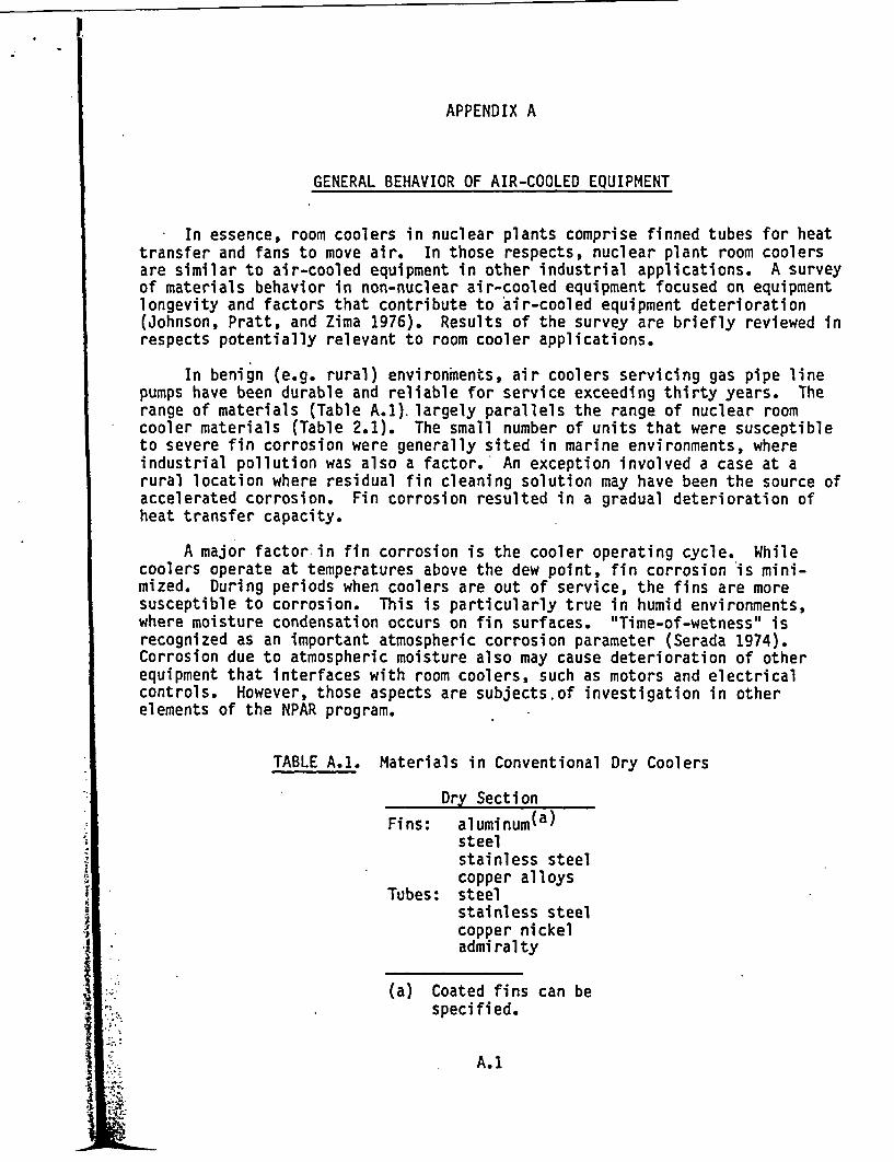
APPENDIX A
GENERAL BEHAVIOR OF AIR-COOLED EQUIPMENT
In essence, room coolers in nuclear plants comprise finned tubes for heattransfer and fans to move air. In those respects, nuclear plant room coolersare similar to air-cooled equipment in other industrial applications. A surveyof materials behavior in non-nuclear air-cooled equipment focused on equipmentlongevity and factors that contribute to air-cooled equipment deterioration(Johnson, Pratt, and Zima 1976). Results of the survey are briefly reviewed inrespects potentially relevant to room cooler applications.
In benign (e.g. rural) environments, air coolers servicing gas pipe linepumps have been durable and reliable for service exceeding thirty years. Therange of materials (Table A.1). largely parallels the range of nuclear roomcooler materials (Table 2.1). The small number of units that were susceptibleto severe fin corrosion were generally sited in marine environments, whereindustrial pollution was also a factor. An exception involved a case at arural location where residual fin cleaning solution may have been the source ofaccelerated corrosion. Fin corrosion resulted in a gradual deterioration ofheat transfer capacity.
A major factor in fin corrosion is the cooler operating cycle. Whilecoolers operate at temperatures above the dew point, fin corrosion is mini-mized. During periods when coolers are out of service, the fins are moresusceptible to corrosion. This is particularly true in humid environments,where moisture condensation occurs on fin surfaces. "Time-of-wetness" isrecognized as an important atmospheric corrosion parameter (Serada 1974).Corrosion due to atmospheric moisture also may cause deterioration of otherequipment that interfaces with room coolers, such as motors and electricalcontrols. However, those aspects are subjects.of investigation in otherelements of the NPAR program.
TABLE A.1. Materials in Conventional Dry Coolers
Dry Section
Fins: aluminum(a)steelstainless steelcopper alloys
Tubes: steelstainless steelcopper nickeladmiralty
(a) Coated fins can bespecified.
J
A. 1

Material selection is another important consideration in finned tubedurability, particularly in environments where corrosion rates are significant(Uhlig 1967). Copper ions have a demonstrated accelerating effect on aluminumcorrosion. Aluminum fins interface satisfactorily with copper tubes in rela-tively dry conditions. When moist conditions result in some dissolution ofcopper ions, accelerated corrosion of adjacent aluminum may result, dependingon several factors, including time-of-wetness, temperature, and impurities inthe environment. Under dry conditions, copper alloy tubes with aluminum finshave operated without problems over extended periods.
In coolers operating with good water quality control and flow design,water-side corrosion of tubes has not been a significant problem. Fouling ofinterior tube surfaces also has not limited thermal performance. If coolerwater quality is marginal, or if sea water serves as the coolant, materialsselection becomes a key consideration. The survey provides a review of corro-sion behavior of candiddte air cooler materials, including aqueous and airenvironments.
From the survey, additional problems and considerations in air-cooledequipment operation are summarized below:
* Vibration generally was due to loose supports and unbalanced fans.
* Fan motor failures were due to sub-standard motors and to inadequatemaintenance; some motor bearing failures were indicated.
* Gear box failures have occurred due to shock loads and loss oflubricant.
* Some fan blade failures have occurred, principally from stress corro-sion cracking of stainless steel blades; steel and plastic bladesperformed satisfactorily.
* Tube failures caused by freezing, and fouling of fin surfaces byairborne debris are not problems likely to be encountered by roomcoolers in nuclear plants.
From the standpoint of room cooler operation, the most relevant insightsfrom the survey are:
* Air-cooled equipment has a history of high reliability over extendedoperation (>30 y).
* Slow, rather than sudden, deterioration of heat transfer capacity hasoccurred in the few cases where corrosion and fouling have beensevere.
* Air-side corrosion generally was more significant when equipment wasnot operating, particularly in humid environments; the key aspect iswater condensation on corrosion-prone surfaces; air contaminants alsowere important in cases of severe air cooler corrosion.
A.2

* For coolers with corrosion-prone materials or combinations of mate-rials, periodic inspections are suggested (including inspection ofcontacts between fins and tubes when dissimilar metals are involved).
* Room cooler water quality is an important consideration; if sea wateror other potentially aggressive waters are involved, a review ofexpected compatibility with tube materials is recommended. If tubecorrosion and/or deposition is suspected or indicated, the need forfurther inspection or nondestructive evaluation is suggested.
REFERENCES
Johnson, A. B. Jr., D. R. Pratt and G. E. Zima. 1976. A Survey of Materialsand Corrosion Performance in Dry Cooling Applications. BNWL-1958, PacificNorthwest Laboratory, Richland, Washington.
Serada, P. J. 1974. Weathering Factors Affecting Corrosion of Metals inCorrosion in Natural Environments. ASTM SIP 588, American Society forTesting and Materials.
Uhlig, H. H. 1967. Corrosion and Corrosion Control, p. 226. John Wiley andSons, New York.
A.3

APPENDIX B
LIST OF FSARs/PSARs REVIEWED

If t
*
APPENDIX B
LIST OF FSARs/PSARs REVIEWED
The following list contains nuclear system suppliers and original nuclearplant FSARs/PSARs reviewed during the ECCS pump room cooler assessment:
General Electric
ArnoldBrowns Ferry 1, 2, & 3Brunswick 1 & 2FitzpatrickGrand Gulf 1 & 2Oyster CreekPerry 1 & 2Pilgrim
Babcock and Wilcox
Arkansas One -1Davis Besse-1Midland 1 & 2Oconee 1, 2, & 3Rancho Seco
Combustion Engineering
Arkansas One-2Calvert Cliffs 1 & 2Maine YankeeMillstone 2Palo Verde 1,.2, & 3St. Lucie 1 & 2
Westinghouse
Beaver Valley 1 & 2Byron 1 & 2Connecticut YankeeFarley 1 & 2GinnaIndian Point #3KewauneePoint Beach 1 & 2Salem 1Sequoyah 1 & 2TrojanTurkey Point 3 & 4
B.1

PNL-5722
DISTRIBUTION
No. ofCopies
No. ofCopies
OFFSITE
2 U.S. Nuclear RegulatoryCommission
Division of TechnicalInformation and DocumentControl
7920 Norfolk AvenueBethesda, MD 20014
10 J. P. VoraU.S. Nuclear RegulatoryCommission
Electrical Engineering BranchMS 1130Washington, DC 20555
J. J. CareyElectric Power Research
InstituteP.O. Box 10412Palo Alto, CA 94304
M. SubudhiEngineering and Risk AssessmentDivision
Department of Nuclear EnergyBrookhaven National LaboratoryUpton, New York 11973
J. H. TaylorEngineering and Risk Assessment
DivisionDepartment of Nuclear EnergyBrookhaven National LaboratoryUpton, New York 11973
M. L. StanleyIdaho Nuclear EngineeringLaboratory
P.O. Box 1625Idaho Falls, ID 83401
Dr. Salvatore CarfagnoFranklin Research InstituteBenjamin Franklin ParkwayPhiladelphia, PA 19130
Dr. D. M. EissenbergOak Ridge National LaboratoryP.O. Box YOak Ridge, TN 37830
G. A. MurphyOak Ridge National LaboratoryP.O. Box YOak Ridge, TN 37830
R. J. BorkowskiOak Ridge National LaboratoryP.O. Box YOak Ridge, TN 37830
J. W. ClevelandSEA Engineering ConsultantsSuite 3031625 The AlamedaSan Jose, CA 95126
H. McCluerWashington Public Power Supply
SystemWNP No. 2 ColumbiaRichland, WA 99352
M. KippesWashington Public Power SupplySystem
WNP No. 2 ColumbiaRichland, WA 99352
J. E. RhoadsWashington Public Power SupplySystem
3040 George Washington WayRichland, WA 99352A
I.;
'L
Distr-1
pflmwL

1. -v .. .
No. ofCopies
D. J. PawlakEllis and Watts4400 Glen Willow Lake LaneP.O. Box 44010Cincinnati, OH 45244
ONSITE
38 Pacific Northwest Laboratory
R. P. AllenD. E. Blahnik (10)D. A. Diigee
No. ofCopies
M. D. FreshleyR. L. Goodman (5)R. L. GruelD. K. HilliardD. B. JarrellB. M. JohnsonA. B. Johnson, Jr. (5)D. K. KreidI. S. LevyW. B. ScottJ. W. VausePublishing Coordination (2)Technical Information (5)
.istr-2
Distr-2
2
7
*
N F
W