p.o. box 455 icrocontrollers - electrical, computer …ece-siewerts/ecen/hardware/pdf/n… · ·...
TRANSCRIPT

Page 1
MIC
RO
CO
NT
RO
LL
ER
S
www.controleverything.com
P.O. Box 455 Osceola, MO 64776
National Control Devices Phone: 417-646-5644 Fax: 417-646-8302 Email: [email protected]
Absolute Maximum Ratings Normal Operating Conditions Minimum Typical Maximum V+ Supply Voltage 3 Volts 5 Volts 6.25 Volts
Supply Current at 4 MHz 2 ma 3.6 ma Supply Current at 2 MHz .4 ma .9 ma Supply Current at 500 KHz .2 ma .7 ma Input Low Voltage Ground Ground .15 Volts Input High Voltage .6 Volts V+ Output Low Voltage .5 Volts Output High Voltage V+ -.5 Volts Single Pin Current Draw 20 ma Current Draw from all Pins 40 ma
Who’s Controlling Your World?
T he NCD Series Preprogrammed Microcontrollers can be found in control applications all over the world. Our microcontrollers have
a proven reputation for reliability and sim-plicity, offering an off-the-shelf solution for your OEM product.
Our extensive line of preprogrammed mi-crocontrollers offer your corporation, uni-versity, or small business a cost competi-tive edge by significantly reducing design time and engineering costs.
NCD Microprocessors have been avail-able since 1994 and our product line is always growing. With our extensive col-lection of CPUs already in daily operation all over the world, our product line is here to stay and to grow with all of your com-puter control needs.
Preprogrammed Microcontrollers Preprogrammed Microcontrollers Preprogrammed Microcontrollers Preprogrammed Microcontrollers for Advanced Control Applicationsfor Advanced Control Applicationsfor Advanced Control Applicationsfor Advanced Control Applications
NCD Supported CPU Families CPU Pins Speed Package
PIC12C671/672 8 INT, 4 MHz* DIP/SOIC
PIC16C54A 18 4 MHz* DIP/SOIC
PIC16C71 18 <=4 MHz* DIP/SOIC
PIC16C554A 18 4 MHz* DIP/SOIC
PIC16C62 18 <=20 MHz DIP/SOIC
PIC16C715 18 <= 20 MHz DIP/SOIC
PIC16C73B 28 <= 20 MHz DIP
PIC16C74B 40 <=20 MHz DIP
PIC16C77B 40 <=20 MHz DIP
PIC17C42 40 <=16 MHz DIP
PIC17C43 40 <=20 MHz DIP
PIC17C44 40 <=20 MHz DIP
PIC17C756 68 <=33 MHz PLCC INT=Internal Oscillator, *=OK to Over-clock at 8 MHz.

Page 2
PO
LIC
Y &
PR
EC
AU
TIO
NS
www.controleverything.com
P.O. Box 455 Osceola, MO 64776
National Control Devices Phone: 417-646-5644 Fax: 417-646-8302 Email: [email protected]
Who’s Controlling Your World?
Static Sensitivity NCD Preprogrammed microcontrollers are static sensitive. Neutralize static in your body by touching a grounded surface BEFORE handling.
Prototyping DO NOT USE NCD MICROCONTROLLERS ON A BREADBOARD, DEVICE FAILURE MAY OCCUR. Breadboards often disrupt the oscillator lines result-ing in unreliable operation and in most cases, device failure. Only Byte Bugs that do not rely on an external oscillator may be prototyped on a breadboard. All other devices require the use of a solder-based prototyping board. We rec-ommend the use of IC sockets when prototyping. External crystals or resona-tors must be soldered as close to the oscillator lines as possible.
Monitoring Never monitor the oscillator lines of an NCD preprogrammed microcontroller with an oscilloscope. Doing may damage the device permanently.
Returns NCD Preprogrammed microcontrollers cannot be returned or replaced if the original sealed packaging is broken.
Firmware Errors While every precaution has been taken to prevent firmware errors, it is possible for minor bugs to escape our testing procedures. Unless otherwise noted, we do not accept ANY responsibility for firmware errors that may be discovered by our users. We will make every effort to update the firmware to correct the problem for future purchases. However, devices cannot be returned for refund or exchange based on firmware errors.
Firmware Upgrade Policy We currently do not offer any price breaks for firmware upgrades of any kind.
Technical Support Technical support is only available via e-mail: [email protected]

Page 3
FA
MIL
Y S
EL
EC
TOR
www.controleverything.com
P.O. Box 455 Osceola, MO 64776
National Control Devices Phone: 417-646-5644 Fax: 417-646-8302 Email: [email protected]
Who’s Controlling Your World?
First Generation NCD Series Page 4 The original NCD Series preprogrammed microcontrollers were our first line of micro-controller-based products originally released under the SMI name in 1994. We have included the original data sheets in this archive and continue to offer this popular se-ries of diverse micros. The first generation NCD series offer simple and inexpensive computer control functions such as serial-to-parallel conversion, parallel-to-serial en-coding, keypad encoding, 8-bit A/D, as well as custom timer functions. The first gen-eration microcontrollers are exclusively 18-pin devices based on the PIC16C54A and PIC16C71 Microcontrollers. The NCD series were very powerful for their time, but we may offer a high-speed update in the AFC family below.
Byte Bugs Page 5 Byte Bugs are typically 8-Pin devices available in DIP and SOIC packages. They are very low cost and easy to use, concentrating on simplicity rather than functionality. If you are new to computer control, Byte Bugs are an excellent place to start. Byte Bugs do not often incorporate a lot of fancy features and only need a couple of external components for operation. Byte Bugs often run at 2400 or 9600 baud and some do not require an ex-ternal crystal or ceramic resonator. While Byte Bugs are easy to use, some incorporate the E3C command set allowing up to 256 different bugs to be individually controlled from a single RS-232 serial port Basic Stamp I/O Pin. Never underestimate the power of Byte Bugs when several different types are ganged together on a single serial port.
Advanced Function Controllers Page 6Advanced Function Controllers (AFCs) are our latest and most innovative family of preprogrammed microcontrollers. AFCs are typically E3C compliant, allowing 256 de-vices to share a single serial port. Many AFCs support user-selectable baud rates of 1200-115.2K baud. AFCs are not limited to computer control applications. Some AFCs, such as our LED VU Meter Drivers, do not necessitate an external computer or microcontroller. AFCs are programmed for A/D conversion, digital I/O, LED drivers, LCD/VFD controllers, and much more. Most AFCs incorporate a hardware USART for excellent RS-232 reliability. Any new device with more than 8-pins beginning in Janu-ary of 2000 will be released as an AFC microcontroller.
Replacement Microcontrollers Page 8 Microcontrollers are available to replace damaged microcontrollers used exclusively in NCD circuit boards. Design schematics are not available for all devices.
Analog Control Processors Page 7 Analog Control Processors are used in real-world electronic design applications and do not usually require a computer or other external system. ACPs include our VU LED Level Meter Display Controllers, light/dark activated switches, and much more.
Page 4
DE
VIC
E S
EL
EC
TOR
www.controleverything.com
P.O. Box 455 Osceola, MO 64776
National Control Devices Phone: 417-646-5644 Fax: 417-646-8302 Email: [email protected]
Who’s Controlling Your World?
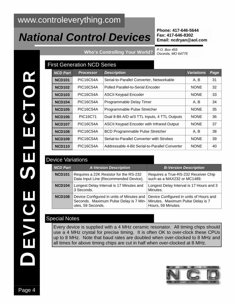
First Generation NCD Series NCD Part Processor Description Variations Page
NCD101 PIC16C54A Serial-to-Parallel Converter, Networkable A, B 31
NCD102 PIC16C54A Polled Parallel-to-Serial Encoder NONE 32
NCD103 PIC16C54A ASCII Keypad Encoder NONE 33
NCD104 PIC16C54A Programmable Delay Timer A, B 34
NCD105 PIC16C54A Programmable Pulse Stretcher NONE 35
NCD106 PIC16C71 Dual 8-Bit A/D w/3 TTL Inputs, 4 TTL Outputs NONE 36
NCD107 PIC16C54A ASCII Keypad Encoder with Infrared Output NONE 37
NCD108 PIC16C54A BCD Programmable Pulse Stretcher A, B 38
NCD109 PIC16C54A Serial-to-Parallel Converter with Strobes NONE 39
NCD110 PIC16C54A Addressable 4-Bit Serial-to-Parallel Converter NONE 40
Device Variations NCD Part A-Version Description B-Version Description
NCD101 Requires a 22K Resistor for the RS-232 Data Input Line (Recommended Device).
Requires a True-RS-232 Receiver Chip such as a MAX232 or MC1489.
NCD104 Longest Delay Interval is 17 Minutes and 3 Seconds.
Longest Delay Interval is 17 Hours and 3 Minutes.
NCD108 Device Configured in units of Minutes and Seconds. Maximum Pulse Delay is 7 Min-utes, 59 Seconds.
Device Configured in units of Hours and Minutes. Maximum Pulse Delay is 7 Hours, 59 Minutes.
Special Notes Every device is supplied with a 4 MHz ceramic resonator. All timing chips should use a 4 MHz crystal for precise timing. It is often OK to over-clock these CPUs up to 8 MHz. Note that baud rates are doubled when over-clocked to 8 MHz and all times for above timing chips are cut in half when over-clocked at 8 MHz.

Page 5
DE
VIC
E S
EL
EC
TOR
www.controleverything.com
P.O. Box 455 Osceola, MO 64776
National Control Devices Phone: 417-646-5644 Fax: 417-646-8302 Email: [email protected]
Who’s Controlling Your World?
Byte Bug Series NCD Part Name E3C Description Page
NCD201 Anabug No 4-Ch. 8-Bit A/D + 1 TTL Input w/2400 Baud 7-Byte Packet Output 9
NCD202 Anabug2 No 2-Channel A/D Converter + 1 TTL Input w/9600 Baud 5-Byte Packet Output 11
NCD203 Anabug3 No 2-Channel A/D Converter w/Enable & 9600 Baud 4-Byte Packet Output 13
NCD204 Anabug4 Yes 2-Channel A/D Converter, Polled 2-Way RS-232 w/9600 Baud Output 15
NCD205 AnabugXT No 4-Channel A/D + 8-Bit Input, Up to 19.2K Baud 7-Byte Packet Output 17
NCD206 AnabugHS No 4-Channel A/D + 8-Bit Input, Up to 48K Baud 7-Byte Packet Output 17
NCD207 Bitabug No 5-Bit Serial to Parallel Converter with 2400 Baud Input 19
NCD208 Bitabug2 No 3-Bit Serial to Parallel Converter with 9600 Baud Input 21
NCD209 Scam Yes Networkable Dual Servo Driver for Remote Camera Positioning Applications 23
NCD210 Scam2 Yes Networkable 3-Servo Driver for Remote Camera Positioning Applications 26
NCD220 Bitabug3 Yes Networkable 3-Bit Output, 9600 Baud 28
NCD219 JoyScam Yes Joystick Position Encoder, Packet Generator for NCD209 SCAM Chip 30
Special Notes E3C Compliant Devices allow 256 Devices to share a single serial port. The device number is burned into the chip prior to shipment. Parts should be ordered with a device number of 000-255 at the end of part numbers above. If no device number is given at the time of order, chips will be burned as device 000. Most Byte Bugs require an external ceramic resonator. Those that require an external resonator are supplied with the appropriate resonator. Byte Bugs are typically devel-oped around the PIC12C671/672 and PIC16C71/73/74 microcontroller cores.
ORDER FORM Page 46

Page 6
DE
VIC
E S
EL
EC
TOR
www.controleverything.com
P.O. Box 455 Osceola, MO 64776
National Control Devices Phone: 417-646-5644 Fax: 417-646-8302 Email: [email protected]
Who’s Controlling Your World?
Advanced Function Controllers NCD Part Name E3C Description Page
AS1 AudioScope1 No 16x10 LED Display Driver w/Dot/Bar/Peak Hold 37
AS2 AudioScope2 No As Above with 16 Analog Input Channels 38
PG PlotGraph Yes 16x10 Programmable LED Matrix 39
VUM VUMeter No 10x2 Stereo LED Display Driver w/Dot/Bar/Peak Hold 40
KC KeyCoder No Programmable Relay Lock/Unlock with Keypad Input 41
Special Notes E3C Compliant Devices allow 256 Devices to share a single serial port. The device number is burned into the chip prior to shipment. Parts should be ordered with a device number of 000-255 in place of –XXX in the part numbers above. If no device number is given at the time of order, chips will be burned as device 000. Most Byte Bugs do NOT require an external ceramic resona-tor. Those that require an external resonator are supplied with the appropriate resonator. Byte Bugs are developed around the PIC12C671/672 microcontroller core.
Watch for New Custom Controllers in the Coming Months.
E3C Compliant Devices allow 256 Devices to share a single serial port. The device number is burned into the chip prior to shipment. Parts should be ordered with a device number of 000-255 at the end of part numbers above. If no device number is given at the time of order, chips will be burned as device 000. Most Byte Bugs do NOT require an external ceramic resonator. Those that require an external resonator are supplied with the appropriate resonator. Byte Bugs are de-veloped around the PIC12C671/672 microcontroller core.

Page 7
DE
VIC
E S
EL
EC
TOR
www.controleverything.com
P.O. Box 455 Osceola, MO 64776
National Control Devices Phone: 417-646-5644 Fax: 417-646-8302 Email: [email protected]
Who’s Controlling Your World?
Analog Control Processors NCD Part Name Description Page
NCD301 VUM 2x10 LED Stereo VU Meter Display Driver w/Dot/Bar/Peak Hold & Fall 28
NCD302 VUM2 Single Channel 20 LED VU Meter Display Driver w/Dot/Bar/Peak Hold & Fall 29
PG Plot-Graph
16x10 Programmable LED Matrix 39
VUM VUMeter
10x2 Stereo LED Display Driver w/Dot/Bar/Peak Hold 40
KC Key-Coder
Programmable Relay Lock/Unlock with Keypad Input 41
Special Notes E3C Compliant Devices allow 256 Devices to share a single serial port. The device number is burned into the chip prior to shipment. Parts should be ordered with a device number of 000-255 in place of –XXX in the part numbers above. If no device number is given at the time of order, chips will be burned as device 000. Most Byte Bugs do NOT require an external ceramic resona-tor. Those that require an external resonator are supplied with the appropriate resonator. Byte Bugs are developed around the PIC12C671/672 microcontroller core.
Watch for New Custom Controllers in the Coming Months.
E3C Compliant Devices allow 256 Devices to share a single serial port. The device number is burned into the chip prior to shipment. Parts should be ordered with a device number of 000-255 at the end of part numbers above. If no device number is given at the time of order, chips will be burned as device 000. Most Byte Bugs do NOT require an external ceramic resonator. Those that require an external resonator are supplied with the appropriate resonator. Byte Bugs are de-veloped around the PIC12C671/672 microcontroller core.

Page 8
DE
VIC
E S
EL
EC
TOR
www.controleverything.com
P.O. Box 455 Osceola, MO 64776
National Control Devices Phone: 417-646-5644 Fax: 417-646-8302 Email: [email protected]
Who’s Controlling Your World?
Replacement Microcontrollers NCD Part NCD Board Name Description Price
8SCRK 8SC 8-Bit Input Scanner Repair Kit $12
ABTRK ABT ASCII Backpack Transmitter Repair Kit $12
AKTRK AKT ASCII Keypad Transmitter Repair Kit $12
AD8RK AD8 Dual 8-Bit A/D w/TTL I/O Repair Kit $12
NCD110 ASEL PIC Microcontroller for ASEL $10
GDSPRK GDSP GDSP 240x64 LCD Display Controller Repair Kit $29
NCD110 IR8 PIC Microcontroller for IR8 $10
N/A IRTR DEVICE MUST BE RETURNED FOR REPAIR -
LCDM LCD PIC Microcontroller for LCD Char. Display Controller $10
N/A LCDA128 DEVICE MUST BE RETURNED FOR REPAIR -
PWM M1 PWM Chip for M1 DC Motor Controller $10
NCD110 M1 PIC Microcontroller for M1 RS-232 Interface $10
NCD110 R45/R410 PIC Microcontroller for R45/R410 Relay Controller $10
R8XM R85/R810 PIC Microcontroller for R85/R810 Relay Controller $20
R16XM R16xx PIC Microcontroller for R16 Series Relay Controllers $40
N/A RSB DEVICE MUST BE REPLACED, NO REPAIRS -
NCD110 STP PIC Microcontroller for STP Stepper Controller $10
GATEWAY SV8/16 PIC Microcontroller for SVx. RS-232 Interface Chip. $10
SVM SV8/16 PIC Microcontroller for SVx. Servo Control Chip. $15
VFDM VFD PIC Microcontroller for VFD Display Controller $60
Special Notes Most NCD Devices are user-repairable by simply replacing the PIC microcontroller. While we do request that you return your device for repair, we do offer you the option of repairing the device yourself by purchasing the appropriate replacement microprocessor. Antistatic precautions must be observed when replacing NCD microcontrollers.

Page 9
B BBBY
TE
YT
EY
TE
YT
E B B B B
UG
SU
GS
UG
SU
GS
: ::: A AAA
NA
BU
GN
AB
UG
NA
BU
GN
AB
UG
www.controleverything.com
P.O. Box 455 Osceola, MO 64776
National Control Devices Phone: 417-646-5644 Fax: 417-646-8302 Email: [email protected]
Who’s Controlling Your World?
Device Description: NCD201
Recommended Usage This device is provided with programming examples for the following systems. If programming examples are not provided for the Basic Stamp, then it is NOT RECOMENDED for use with this device at this time. E3C Compliance allows 256 Devices to interface to a single serial port.
Anabug is a 8-pin preprogrammed microcontroller based on the PIC12C671/672 core, and is available in DIP and SOIC packages. Anabug is programmed to read four 8-bit analog inputs (0-5 volts DC) and one digital input (TTL/CMOS Compatible) and generate a packet of 7 bytes indicating the status of all inputs. Packets of data are continuously sent out the RS-232 Data Output pin (RS0) at 2400 baud.
QBasic Visual Basic 6 Pro Basic Stamp II Basic Stamp II SX E3C Compliance
No Yes No No No
Example Device Wiring: NCD201 Anabug, shown at left, is easily connected to the serial port of your computer using only a 220 Ohm resistor. Anabug requires a regulated +5 volt power supply. Anabug has five inputs, one is a standard TTL/CMOS (0/+5 volt) input and the other four are analog inputs. Analog inputs can accept an input voltage range of 0 to 5 volts DC. Anabug is shown with its analog inputs connected to four potentiometers. When power is applied, data packets of 7 bytes will be continuously sent to the computer at 2400 baud, indicating the status of all 5 inputs.
DB9 Female: Solder SideConnect to any AvailableRS-232 Serial Port.+5
DigitalInput
AN0
AN1
AN2
AN3
DI
RSO
GND+5
Analog Inputs 1-4
Current Pricing in US Dollars: NCD201 Package Type Qty 1-9 Qty 10 Qty 11-100 Qty 101-1000
DIP DISCONTINUED DISCONTINUED DISCONTINUED DISCONTINUED SOIC DISCONTINUED DISCONTINUED DISCONTINUED DISCONTINUED
Pin Label Function 1 +5 Connect to Regulated +5 Supply
2 RSO RS-232 Data Output, 2400 bps, 8,N,1
3 AN3 Analog Input 4
4 AN2 TTL/CMOS Digital Input
5 AN2 Analog Input 3
6 AN1 Analog Input 2
7 AN0 Analog Input 1
8 GND Power Supply Ground
NCD201

Page 10
P PPPR
OG
RA
MM
ING
RO
GR
AM
MIN
GR
OG
RA
MM
ING
RO
GR
AM
MIN
G A AAA
NA
BU
GN
AB
UG
NA
BU
GN
AB
UG
www.controleverything.com
P.O. Box 455 Osceola, MO 64776
National Control Devices Phone: 417-646-5644 Fax: 417-646-8302 Email: [email protected]
Who’s Controlling Your World?
Programmers Notes Anabug constantly generates packets of data at 2400 baud. A packet of data consists of 7 bytes, indicating the status of all inputs. Data packets are organized as shown in the
table (left). Note that data packets are sent ~ 30 times per second. A program used to decode these data packets must look for the header, store the incoming data, and only accept the data if the footer is detected as byte 7. Otherwise, the data packet should be discarded to prevent reception errors. Note that all in-puts should be tied low with a 4.7K resis-tor to prevent channel bleed.
Example Software Notes Example communication software for this device was written under Visual Basic 6 Professional. Example source code can be downloaded from our web site at www.controleverything.com. If you are NOT a Visual Basic Programmer, Source code can be viewed using a text editor such as Notepad or WordPad. Source code is clearly commented for easy migration to other languages.
Programming Language
Program Program Description
Basic Stamp II NONE Anabug has not been tested with the Basic Stamp II
Basic Stamp II SX NONE Anabug has not been tested with the Basic Stamp II SX
QBasic NONE Coming Soon
Visual Basic 6 Pro BUGS.ZIP Simple Program Graphically Displays the Status of all 5 Inputs
Byte Value Description 1 254 Header Byte, Begins the Packet
2 0-255 Analog Value of Input Channel 1
3 0-255 Analog Value of Input Channel 2
4 0-255 Analog Value of Input Channel 3
5 0-255 Analog Value of Input Channel 4
6 0-1 Logic Level Input Status (1=High)
7 85 Footer Byte, Concludes the Packet
Important Availability Information The Anabug will be replaced by the Anabug2 due to unreliable calibration issues with the internal oscillator. Anabug2 will require an external resonator at the sacrifice of 2 input channels. Please call us if your application absolutely requires the original Anabug.
NCD201

Page 11
B BBBY
TE
YT
EY
TE
YT
E B B B B
UG
SU
GS
UG
SU
GS
: ::: A AAA
NA
BU
GN
AB
UG
NA
BU
GN
AB
UG
2 222
www.controleverything.com
P.O. Box 455 Osceola, MO 64776
National Control Devices Phone: 417-646-5644 Fax: 417-646-8302 Email: [email protected]
Who’s Controlling Your World?
Device Description: NCD202
Recommended Usage This device is provided with programming examples for the following systems. If programming examples are not provided for the Basic Stamp, then it is NOT RECOMENDED for use with this device at this time. E3C Compliance allows 256 Devices to interface to a single serial port.
Anabug2 is a 8-pin preprogrammed microcontroller based on the PIC12C671/672 core, and is available in DIP and SOIC packages. Anabug2 is programmed to read two 8-bit analog inputs (0-5 volts DC) and one digital input (TTL/CMOS Compatible) and generate a packet of 5 bytes indicating the status of all inputs. Packets of data are continuously sent out the RS-232 Data Output pin (RS0) at 9600 baud.
QBasic Visual Basic 6 Pro Basic Stamp II Basic Stamp II SX E3C Compliance
No Yes No No No
Example Device Wiring: NCD202 Anabug2, shown at left, is easily connected to the serial port of your computer using only a 220 Ohm resistor. Anabug2 requires a regulated +5 volt power supply. Anabug2 has three inputs, one is a standard TTL/CMOS (0/+5 volt) input and the other two are analog inputs. Analog inputs can accept an input voltage range of 0 to 5 volts DC. Anabug2 is shown with its analog inputs connected to two potentiometers. When power is applied, data packets of 5 bytes will be continuously sent to the computer at 9600 baud, indicating the status of all three inputs.
+5
DigitalInput
RSO
AN0
AN1
OSC
DI
OSC
GND+5
4 MHz
Analog Inputs 1 & 2
RS-232 Connector: Solder Side of DB-9 Female Shown.
Current Pricing in US Dollars: NCD202 Package Type Qty 1-9 Qty 10-25 Qty 26-100 Qty 101+
DIP $10 $5.90 $5.10 MARKET PRICE
SOIC $11 $6.90 $6.10 MARKET PRICE
Pin Label Function 1 +5 Connect to Regulated +5 Supply
2, 3 OSC Ceramic Resonator Connection
4 DI TTL/CMOS Digital Input
5 AN1 Analog Input 1
6 AN0 Analog Input 0
7 RSO RS-232 Data Output, 9600 bps, 8,N,1
8 GND Power Supply Ground
NCD202

Page 12
P PPPR
OG
RA
MM
ING
RO
GR
AM
MIN
GR
OG
RA
MM
ING
RO
GR
AM
MIN
G A AAA
NA
BU
GN
AB
UG
NA
BU
GN
AB
UG
2 222
www.controleverything.com
P.O. Box 455 Osceola, MO 64776
National Control Devices Phone: 417-646-5644 Fax: 417-646-8302 Email: [email protected]
Who’s Controlling Your World?
Programmers Notes Anabug2 constantly generates packets of data at 9600 baud. A packet of data consists of 5 bytes, indicating the status of all inputs. Data packets are organized as shown in the table (below). Note that data packets are sent ~ 30 times per second. A program used
to decode these data packets must look for the header (254), store the incoming data, and only accept the data if the footer is detected as byte 5. Otherwise, the data packet should be discarded to prevent reception errors. Note that all in-puts should be tied low with a 4.7K resis-tor to prevent channel bleed.
Example Software Notes Example communication software for this device was written under Visual Basic 6 Professional.
Programming Language
Program Program Description
Basic Stamp II NONE Anabug has not been tested with the Basic Stamp II
Basic Stamp II SX NONE Anabug has not been tested with the Basic Stamp II SX
QBasic NONE Coming Soon
Visual Basic 6 Pro AB.ZIP Simple Program Graphically Displays the Status of all 5 Inputs
Byte Value Description 1 254 Header Byte, Begins the Packet
2 0-255 Analog Value of Input Channel 1
3 0-255 Analog Value of Input Channel 2
4 0-1 Logic Level Input Status (1=High)
5 85 Footer Byte, Concludes the Packet
Availability The Anabug2 will replace the Anabug due to unreliable calibration issues with the internal oscillator. Anabug 2 will begin shipping on February 1, 2000.
Example Software Notes Example communication software for this device was written under Visual Basic 6 Professional. Example source code can be downloaded from our web site at www.controleverything.com. If you are NOT a Visual Basic Programmer, Source code can be viewed using a text editor such as Notepad or WordPad. Source code is clearly commented for easy migration to other languages.
Programming Language
Program Program Description
Basic Stamp II NONE Anabug2 has not been tested with the Basic Stamp II
Basic Stamp II SX NONE Anabug2 has not been tested with the Basic Stamp II SX
QBasic NONE Coming Soon
Visual Basic 6 Pro BUGS.ZIP Simple Program Graphically Displays the Status of all 3 Inputs
NCD202

Page 13
B BBBY
TE
YT
EY
TE
YT
E B B B B
UG
SU
GS
UG
SU
GS
: ::: A AAA
NA
BU
GN
AB
UG
NA
BU
GN
AB
UG
3 333
www.controleverything.com
P.O. Box 455 Osceola, MO 64776
National Control Devices Phone: 417-646-5644 Fax: 417-646-8302 Email: [email protected]
Who’s Controlling Your World?
Device Description: NCD203
Recommended Usage This device is provided with programming examples for the following systems. If programming examples are not provided for the Basic Stamp, then it is NOT RECOMENDED for use with this device at this time. E3C Compliance allows 256 Devices to interface to a single serial port.
Anabug3 is a 8-pin preprogrammed microcontroller based on the PIC12C671/672 core, and is available in DIP and SOIC packages. Anabug3 is programmed to read two 8-bit analog inputs (0-5 volts DC) and generate a packet of 4 bytes indicating the status of both inputs. Packets of data are continuously sent out the RS-232 Data Output pin (RS0) at 9600 baud as long as the Chip Enable (CE) pin is held low. Packets are halted if CE is high. This device always generates 4-byte data packets that are not interrupted if the logic state of CE changes during packet transmission.
QBasic Visual Basic 6 Pro Basic Stamp II Basic Stamp II SX E3C Compliance
No Yes No No No
Example Device Wiring: NCD203 Anabug3, shown at left, is easily connected to the serial port of your computer using only a 220 Ohm resistor. Anabug3 requires a regulated +5 volt power supply. Anabug has two analog inputs. Analog inputs can accept an input voltage range of 0 to 5 volts DC. Anabug3 is shown with its ana-log inputs connected to two potentiometers. When power is applied, data packets of 4 bytes will be continuously sent to the computer at 9600 baud as long as the CE line is held low. Bringing the CE line high disable packet transmission.
+5RSO
AN0
AN1
OSC
CE
OSC
GND+5
4 MHz
Analog Inputs 1 & 2
RS-232 Connector: Solder Side of DB-9 Female Shown.
Chip Enable:Connect to GND toEnable Chip, Packets willbe sent continuously untildisabled.Connect to +5 to Disable.
Pin Label Function 1 +5 Connect to Regulated +5 Supply
2,3 OSC Ceramic Resonator Connection
4 CE Chip Enable, Low to Enable Chip
5 AN1 Analog Input 2
6 AN0 Analog Input 1
7 RSO RS-232 Data Output, 9600 bps, 8,N,1
8 GND Ground
NCD203
Current Pricing in US Dollars: NCD203 Package Type Qty 1-9 Qty 10-25 Qty 26-100 Qty 101+
DIP $10 $5.90 $5.10 MARKET PRICE
SOIC $11 $6.90 $6.10 MARKET PRICE
Page 14
P PPPR
OG
RA
MM
ING
RO
GR
AM
MIN
GR
OG
RA
MM
ING
RO
GR
AM
MIN
G A AAA
NA
BU
GN
AB
UG
NA
BU
GN
AB
UG
3 333
www.controleverything.com
P.O. Box 455 Osceola, MO 64776
National Control Devices Phone: 417-646-5644 Fax: 417-646-8302 Email: [email protected]
Who’s Controlling Your World?
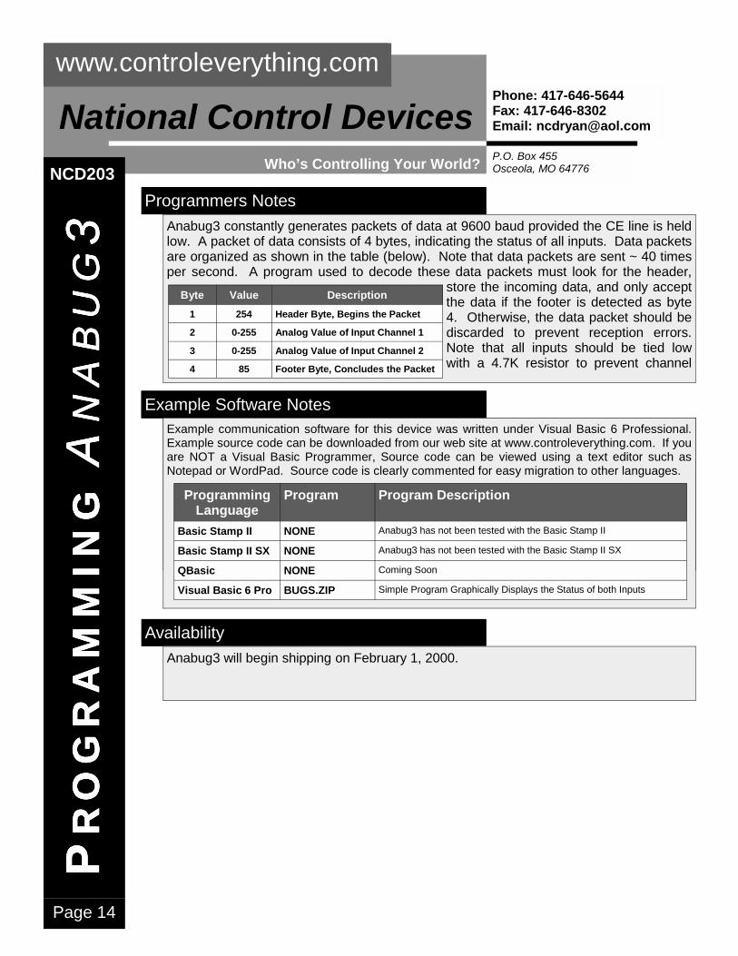
Programmers Notes Anabug3 constantly generates packets of data at 9600 baud provided the CE line is held low. A packet of data consists of 4 bytes, indicating the status of all inputs. Data packets are organized as shown in the table (below). Note that data packets are sent ~ 40 times per second. A program used to decode these data packets must look for the header,
store the incoming data, and only accept the data if the footer is detected as byte 4. Otherwise, the data packet should be discarded to prevent reception errors. Note that all inputs should be tied low with a 4.7K resistor to prevent channel
Byte Value Description 1 254 Header Byte, Begins the Packet
2 0-255 Analog Value of Input Channel 1
3 0-255 Analog Value of Input Channel 2
4 85 Footer Byte, Concludes the Packet
NCD203
Example Software Notes Example communication software for this device was written under Visual Basic 6 Professional.
Programming Language
Program Program Description
Basic Stamp II NONE Anabug has not been tested with the Basic Stamp II
Basic Stamp II SX NONE Anabug has not been tested with the Basic Stamp II SX
QBasic NONE Coming Soon
Visual Basic 6 Pro AB.ZIP Simple Program Graphically Displays the Status of all 5 Inputs
Example Software Notes Example communication software for this device was written under Visual Basic 6 Professional. Example source code can be downloaded from our web site at www.controleverything.com. If you are NOT a Visual Basic Programmer, Source code can be viewed using a text editor such as Notepad or WordPad. Source code is clearly commented for easy migration to other languages.
Programming Language
Program Program Description
Basic Stamp II NONE Anabug3 has not been tested with the Basic Stamp II
Basic Stamp II SX NONE Anabug3 has not been tested with the Basic Stamp II SX
QBasic NONE Coming Soon
Visual Basic 6 Pro BUGS.ZIP Simple Program Graphically Displays the Status of both Inputs
Availability Anabug3 will begin shipping on February 1, 2000.

Page 15
B BBBY
TE
YT
EY
TE
YT
E B B B B
UG
SU
GS
UG
SU
GS
: ::: A AAA
NA
BU
GN
AB
UG
NA
BU
GN
AB
UG
4 444
www.controleverything.com
P.O. Box 455 Osceola, MO 64776
National Control Devices Phone: 417-646-5644 Fax: 417-646-8302 Email: [email protected]
Who’s Controlling Your World?
Device Description: NCD204
Recommended Usage This device is provided with programming examples for the following systems. If programming examples are not provided for the Basic Stamp, then it is NOT RECOMENDED for use with this device at this time. E3C Compliance allows 256 Devices to interface to a single serial port.
Anabug4 is a 8-pin preprogrammed microcontroller based on the PIC12C671/672 core, and is available in DIP and SOIC packages. Anabug4 is a polled device, programmed to read two 8-bit analog inputs (0-5 volts DC) when requested. ASCII character codes are used to issue commands to the Anabug4. Anabug4 sup-ports commands for reading each individual channel or both channels simultaneously. Anabug4 is E3C com-pliant, allowing 256 devices to share a single RS-232 serial port, providing up to 512 A/D channels. E3C compliance allows other types of devices to share the same serial port as well.
QBasic Visual Basic 6 Pro Basic Stamp II Basic Stamp II SX E3C Compliance
No Yes No No Yes
Example Device Wiring: NCD204 Anabug4, shown at left, is easily connected to the serial port of your computer using only two resis-tors. Anabug4 requires a regulated +5 volt power supply. Anabug4 has two analog inputs and an RS-232 I/O port. Analog inputs can accept an input voltage range of 0 to 5 volts DC. Anabug4 is shown with its analog inputs connected to two potentiome-ters. When power is applied, Anabug4 waits for a command from your computer. When the appropri-ate command is received, Anabug4 reads one or both input channels and returns one or two bytes indicating the voltage level on the analog inputs.
+5RSO
AN0
AN1
OSC
RSI
OSC
GND+5
4 MHz
Analog Inputs 1 & 2
RS-232 Connector: Solder Side of DB-9 Female Shown.
NCD204
Current Pricing in US Dollars: NCD204 Package Type Qty 1-9 Qty 10-25 Qty 26-100 Qty 101+
DIP $10 $9.00 $8.10 MARKET PRICE
SOIC $11 $10.00 $9.10 MARKET PRICE
Pin Label Function 1 +5 Connect to Regulated +5 Supply
2, 3 OSC Ceramic Resonator Connection
4 RSI RS-232 Data Input, 9600 bps, 8,N,1
5 AN1 Analog Input 2
6 AN0 Analog Input 1
7 RSO RS-232 Data Output, 9600 bps, 8,N,1
8 GND Ground

Page 16
P PPPR
OG
RA
MM
ING
RO
GR
AM
MIN
GR
OG
RA
MM
ING
RO
GR
AM
MIN
G A AAA
NA
BU
GN
AB
UG
NA
BU
GN
AB
UG
4 444
www.controleverything.com
P.O. Box 455 Osceola, MO 64776
National Control Devices Phone: 417-646-5644 Fax: 417-646-8302 Email: [email protected]
Who’s Controlling Your World?
Programmers Notes Anabug4 supports nine commands for reading analog data and controlling all network functions. Anabug4 is designed to accept and generate numeric ASCII character codes from 0 to 255, easily generated and interpreted by any programming language that supports serial communications. To send a command to Anabug4, you must first send ASCII character code 254 to place the device in command mode. Once in command mode, any of the commands listed in the table below may be issued. Some E3C commands have parameters, used to control which device you are speaking to. To read ana-log input channel 1, ASCII character codes 254 and 0 must be received by the Anabug4. The device will then reply with an ASCII character code from 0-255 indicating the voltage on the analog input. A reply of 0 indicates 0 volts, a reply of 128 indicates 2.5 volts, a reply of 255 indicates 5 volts. E3C compliance allows 256 devices to share a single serial port. Six commands are used to control which device you are speaking to. We do NOT recommend speaking to more than a single device at a time. Doing so would cause significant data collision problems. Therefore, commands 248 and 250 should not be used unless you have made special electrical provisions to accept data from multiple RS-232 data sources simultaneously.
Some E3C commands require a parameter, indicating a specific device number to speak to. In most applications, E3C command 252 will be the only command you will ever need. All other commands are provided for network compliance purposes only. Command 252 is used to speak to an individual device, and turn all others off. To send E3C command 252 to the Anabug4, send ASCII character code 254 to put the Anabug4 in command mode. Next send AS-CII character code 252, followed by a third Parameter indicating which device should be active. All subsequent commands will only be acknowledged by the selected device. Note that E3C device numbers are pro-grammed into the chip at the time of pur-chase. Once programmed, they cannot be changed.
Command Parameter Description 0 None Read A/D Channel 1, Returns 1 Byte
1 None Read A/D Channel 2, Returns 1 Byte
2 None Read A/D Channels 1&2, Returns 2 Bytes
248 None E3C: Enable All Devices
249 None E3C: Disable All Devices
250 0-255 E3C: Enable Selected Device
251 0-255 E3C: Disable Selected Device
252 0-255 E3C: Enable Selected Device, Disable All Other Devices
253 0-255 E3C: Disable Selected Device, Enable All Other Devices
NCD204
Example Software Notes Example communication software for this device was written under Visual Basic 6 Professional.
Programming Language
Program Program Description
Basic Stamp II NONE Anabug has not been tested with the Basic Stamp II
Basic Stamp II SX NONE Anabug has not been tested with the Basic Stamp II SX
QBasic NONE Coming Soon
Visual Basic 6 Pro AB.ZIP Simple Program Graphically Displays the Status of all 5 Inputs
Availability Anabug4 will begin shipping on February 1, 2000.
Example Software Notes Example communication software for this device was written under Visual Basic 6 Professional. Example source code can be downloaded from our web site at www.controleverything.com. If you are NOT a Visual Basic Programmer, Source code can be viewed using a text editor such as Notepad or WordPad. Source code is clearly commented for easy migration to other languages.
Programming Language
Program Program Description
Basic Stamp II NONE Anabug4 has not been tested with the Basic Stamp II
Basic Stamp II SX NONE Anabug4 has not been tested with the Basic Stamp II SX
QBasic NONE Coming Soon
Visual Basic 6 Pro BUGS.ZIP Simple Program Graphically Displays the Status of both Inputs
Page 17
B BBBY
TE
YT
EY
TE
YT
E B B B B
UG
SU
GS
UG
SU
GS
: ::: A AAA
NA
BU
GN
AB
UG
NA
BU
GN
AB
UG
XT
/HS
XT
/HS
XT
/HS
XT
/HS
www.controleverything.com
P.O. Box 455 Osceola, MO 64776
National Control Devices Phone: 417-646-5644 Fax: 417-646-8302 Email: [email protected]
Who’s Controlling Your World?
Device Description: NCD205/6
Recommended Usage This device is provided with programming examples for the following systems. If programming examples are not provided for the Basic Stamp, then it is NOT RECOMENDED for use with this device at this time. E3C Compliance allows 256 Devices to interface to a single serial port.
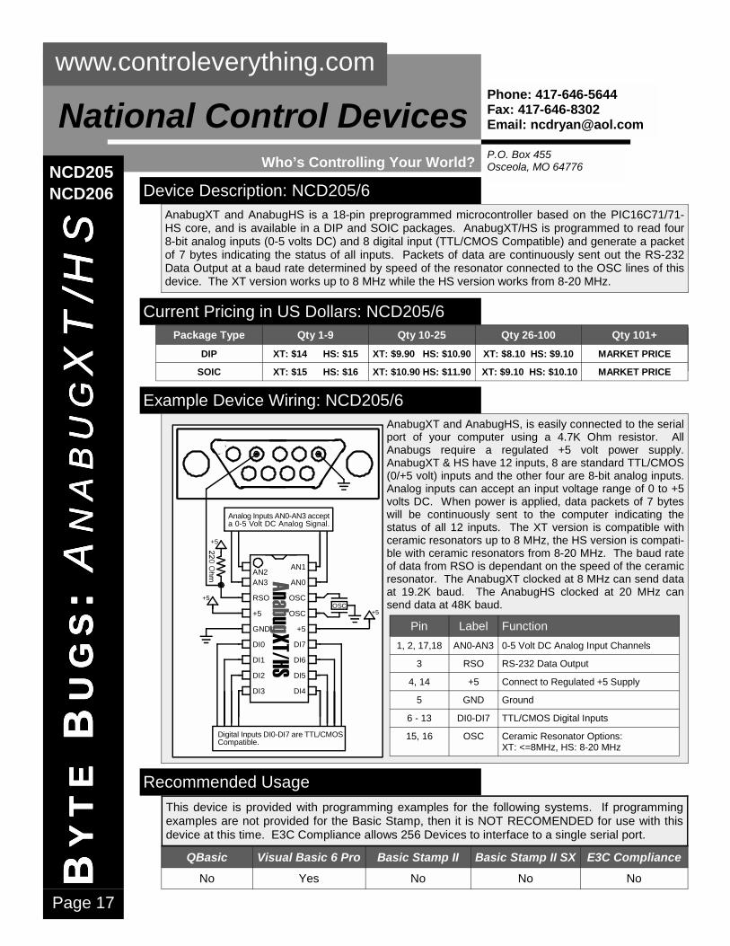
AnabugXT and AnabugHS is a 18-pin preprogrammed microcontroller based on the PIC16C71/71-HS core, and is available in a DIP and SOIC packages. AnabugXT/HS is programmed to read four 8-bit analog inputs (0-5 volts DC) and 8 digital input (TTL/CMOS Compatible) and generate a packet of 7 bytes indicating the status of all inputs. Packets of data are continuously sent out the RS-232 Data Output at a baud rate determined by speed of the resonator connected to the OSC lines of this device. The XT version works up to 8 MHz while the HS version works from 8-20 MHz.
QBasic Visual Basic 6 Pro Basic Stamp II Basic Stamp II SX E3C Compliance
No Yes No No No
Example Device Wiring: NCD205/6 AnabugXT and AnabugHS, is easily connected to the serial port of your computer using a 4.7K Ohm resistor. All Anabugs require a regulated +5 volt power supply. AnabugXT & HS have 12 inputs, 8 are standard TTL/CMOS (0/+5 volt) inputs and the other four are 8-bit analog inputs. Analog inputs can accept an input voltage range of 0 to +5 volts DC. When power is applied, data packets of 7 bytes will be continuously sent to the computer indicating the status of all 12 inputs. The XT version is compatible with ceramic resonators up to 8 MHz, the HS version is compati-ble with ceramic resonators from 8-20 MHz. The baud rate of data from RSO is dependant on the speed of the ceramic resonator. The AnabugXT clocked at 8 MHz can send data at 19.2K baud. The AnabugHS clocked at 20 MHz can send data at 48K baud.
Digital Inputs DI0-DI7 are TTL/CMOSCompatible.
AN3
RSO
+5
GND
DI0
DI1
DI2
DI3
AN1
AN0
OSC
OSC
+5
DI7
DI6
DI5
DI4
Analog Inputs AN0-AN3 accepta 0-5 Volt DC Analog Signal.
AN2
+5
+5
+5OSC
Pin Label Function 1, 2, 17,18 AN0-AN3 0-5 Volt DC Analog Input Channels
3 RSO RS-232 Data Output
4, 14 +5 Connect to Regulated +5 Supply
5 GND Ground
6 - 13 DI0-DI7 TTL/CMOS Digital Inputs
15, 16 OSC Ceramic Resonator Options: XT: <=8MHz, HS: 8-20 MHz
NCD205 NCD206
Current Pricing in US Dollars: NCD205/6 Package Type Qty 1-9 Qty 10-25 Qty 26-100 Qty 101+
DIP XT: $14 HS: $15 XT: $9.90 HS: $10.90 XT: $8.10 HS: $9.10 MARKET PRICE
SOIC XT: $15 HS: $16 XT: $10.90 HS: $11.90 XT: $9.10 HS: $10.10 MARKET PRICE

Page 18
www.controleverything.com
P.O. Box 455 Osceola, MO 64776
National Control Devices Phone: 417-646-5644 Fax: 417-646-8302 Email: [email protected]
Who’s Controlling Your World?
Programmers Notes AnabugXT & HS constantly generates packets of data. A packet of data consists of 7 bytes, indicating the status of all 12 inputs. Data packets are organized as shown in the
table. A program used to decode these data packets must look for the header, 254, store the incoming data (bytes 2-6), and only accept the data packet if the footer byte (85) is detected as byte 7. Otherwise, the data packet should be dis-carded to prevent reception errors. Note that all inputs should be tied low with a 4.7K resistor to prevent channel bleed.
Byte Value Description 1 254 Header Byte, Begins the Packet
2 0-255 Analog Value of Input Channel 1
3 0-255 Analog Value of Input Channel 2
4 0-255 Analog Value of Input Channel 3
5 0-255 Analog Value of Input Channel 4
6 0-255 Logic Status of 8-Bit Input Port
7 85 Footer Byte, Concludes the Packet
P PPPR
OG
RA
MM
ING
RO
GR
AM
MIN
GR
OG
RA
MM
ING
RO
GR
AM
MIN
G A AAA
NA
BU
GN
AB
UG
NA
BU
GN
AB
UG
XT
/HS
XT
/HS
XT
/HS
XT
/HS
NCD205 NCD206
Example Software Notes Example communication software for this device was written under Visual Basic 6 Professional.
Programming Language
Program Program Description
Basic Stamp II NONE Anabug has not been tested with the Basic Stamp II
Basic Stamp II SX NONE Anabug has not been tested with the Basic Stamp II SX
QBasic NONE Coming Soon
Visual Basic 6 Pro AB.ZIP Simple Program Graphically Displays the Status of all 5 Inputs
Availability The AnabugXT and AnabugHS will begin shipping February 1, 2000.
Example Software Notes Example communication software for this device was written under Visual Basic 6 Professional. Example source code can be downloaded from our web site at www.controleverything.com. If you are NOT a Visual Basic Programmer, Source code can be viewed using a text editor such as Notepad or WordPad. Source code is clearly commented for easy migration to other languages.
Programming Language
Program Program Description
Basic Stamp II NONE AnabugXT/HS has not been tested with the Basic Stamp II
Basic Stamp II SX NONE AnabugXT/HS has not been tested with the Basic Stamp II SX
QBasic NONE Coming Soon
Visual Basic 6 Pro BUGS.ZIP Simple Program Graphically Displays the Status of all 12 Inputs
Baud Rate Selector Guide Anabug XT and HS ver-sions provide versatile baud rate selection by simply changing the reso-nator connected to the OSC pins of this device. Simply purchase the reso-nator of your choice from DigiKey using the provided part numbers. The XT version includes a 4 MHz ceramic resonator, the HS version includes a 16 MHz ceramic resonator. Please see the Microchip data sheets for additional infor-mation.
Baud Rate
Clock Speed
DigiKey Part www.digikey.com
Notes NCD Device
1200 500 KHz X922-ND Requires Caps, See Microchip Data Sheet Anabug XT
2400 1000 KHz X926-ND Requires Caps, See Microchip Data Sheet Anabug XT
4800 2 MHz PX200-ND Anabug XT
9600 4 MHz X902-ND Anabug XT
14.4K 6 MHz X904-ND Anabug XT
19.2K 8 MHz X905-ND XT Version can be overclocked to 8 MHz. Anabug XT/HS
24K 10 MHz X906-ND Anabug HS
28.8K 12 MHz X907-ND Anabug HS
38.4K 16 MHz X908-ND Anabug HS
48K 20 MHz X909-ND Anabug HS

Page 19
B BBBY
TE
YT
EY
TE
YT
E B B B B
UG
SU
GS
UG
SU
GS
: ::: B BBB
ITA
BU
GIT
AB
UG
ITA
BU
GIT
AB
UG
www.controleverything.com
P.O. Box 455 Osceola, MO 64776
National Control Devices Phone: 417-646-5644 Fax: 417-646-8302 Email: [email protected]
Who’s Controlling Your World?
Device Description: NCD207
Recommended Usage This device is provided with programming examples for the following systems. If programming examples are not provided for the Basic Stamp, then it is NOT RECOMENDED for use with this device at this time. E3C Compliance allows 256 Devices to interface to a single serial port.
Bitabug is a 8-pin preprogrammed microcontroller based on the PIC12C671/672 core, and is available in DIP and SOIC packages. Bitabug is programmed as a 5-bit serial-to-parallel converter, and will only respond to incoming ASCII character codes in the range of 0 to 31. All other incoming ASCII character codes are ignored.
QBasic Visual Basic 6 Pro Basic Stamp II Basic Stamp II SX E3C Compliance
Compatible Yes Compatible Compatible No
Example Device Wiring: NCD207 Bitabug, shown at left, is easily connected to the serial port of your computer using only a 22K Ohm resistor. Bitabug requires a regulated +5 volt power supply. Bitabug has five TTL/CMOS (0/+5 volt) outputs, which are driven un-der computer control. Bitabug is shown with its digital outputs connected to five LEDs. When power is applied, Bitabug waits for ASCII char-acter codes 0 to 31, the equivalent binary pat-tern is immediately latched to its outputs. ASCII character codes above 31 are ignored by the Bitabug.
DB9 Female: Solder SideConnect to any AvailableRS-232 Serial Port.
1K x 5
+5
RSI
DO0
DO1
DO2
DO4
DO3
GND+522K
Current Pricing in US Dollars: NCD207 Package Type Qty 1-9 Qty 10 Qty 11-100 Qty 101-1000
DIP DISCONTINUED DISCONTINUED DISCONTINUED DISCONTINUED
SOIC DISCONTINUED DISCONTINUED DISCONTINUED DISCONTINUED
NCD207
Pin Label Function 1 +5 Connect to Regulated +5 Supply 2 OSC Ceramic Resonator Connection
3 OSC Ceramic Resonator Connection
4 CE Chip Enable, Low to Enable Chip
5 AN1 Analog Input 2
6 AN0 Analog Input 1
7 RSI RS-232 Data Input, 2400 bps, 8,N,1
8 GND Ground

Page 20
P PPPR
OG
RA
MM
ING
RO
GR
AM
MIN
GR
OG
RA
MM
ING
RO
GR
AM
MIN
G B BBB
ITA
BU
GIT
AB
UG
ITA
BU
GIT
AB
UG
www.controleverything.com
P.O. Box 455 Osceola, MO 64776
National Control Devices Phone: 417-646-5644 Fax: 417-646-8302 Email: [email protected]
Who’s Controlling Your World?
Programmers Notes Bitabug acts as serial-to-parallel converter responding only to ASCII character codes 0 to 31. Bitabug only responds to data at 2400 baud. No other programming information is required to implement this device.
NCD207
Example Software Notes Example communication software for this device was written under Visual Basic 6 Professional.
Programming Language
Program Program Description
Basic Stamp II NONE Anabug has not been tested with the Basic Stamp II
Basic Stamp II SX NONE Anabug has not been tested with the Basic Stamp II SX
QBasic NONE Coming Soon
Visual Basic 6 Pro AB.ZIP Simple Program Graphically Displays the Status of all 5 Inputs
Availability The Bitabug will be replaced by the Bitabug2 due to unreliable calibration issues with the internal oscillator. Bitabug2 will require an external resonator at the sacrifice of 2 out-puts. Please call us if your application absolutely requires the original Bitabug.
Example Software Notes Example communication software for this device was written under Visual Basic 6 Professional. Example source code can be downloaded from our web site at www.controleverything.com. If you are NOT a Visual Basic Programmer, Source code can be viewed using a text editor such as Notepad or WordPad. Source code is clearly commented for easy migration to other languages.
Programming Language
Program Program Description
Basic Stamp II NONE Bitabug has not been tested with the Basic Stamp II
Basic Stamp II SX NONE Bitabug has not been tested with the Basic Stamp II SX
QBasic NONE Coming Soon
Visual Basic 6 Pro BUGS.ZIP Simple Program Graphically Controls the Status of all 5 Outputs

Page 21
B BBBY
TE
YT
EY
TE
YT
E B B B B
UG
SU
GS
UG
SU
GS
: ::: B BBB
ITA
BU
GIT
AB
UG
ITA
BU
GIT
AB
UG
2 222
www.controleverything.com
P.O. Box 455 Osceola, MO 64776
National Control Devices Phone: 417-646-5644 Fax: 417-646-8302 Email: [email protected]
Who’s Controlling Your World?
Device Description: NCD208
Recommended Usage This device is provided with programming examples for the following systems. If programming examples are not provided for the Basic Stamp, then it is NOT RECOMENDED for use with this device at this time. E3C Compliance allows 256 Devices to interface to a single serial port.
Bitabug2 is a 8-pin preprogrammed microcontroller based on the PIC12C671/672 core, and is available in DIP and SOIC packages. Bitabug2 was designed to replace the origi-nal Bitabug, which cannot be produced in OEM quantities. Bitabug2 is programmed as a 3-bit serial-to-parallel converter, and will only respond to incoming ASCII character codes in the range of 0 to 7. All other incoming ASCII character codes are ignored.
QBasic Visual Basic 6 Pro Basic Stamp II Basic Stamp II SX E3C Compliance
Compatible Yes Compatible Compatible No
Example Device Wiring: NCD208 Bitabug2, shown at left, is easily connected to the serial port of your computer using only a 22K Ohm resistor. Bitabug2 requires a regu-lated +5 volt power supply. Bitabug2 has three TTL/CMOS (0/+5 volt) outputs, which are driven under computer control. Bitabug2 is shown with its digital outputs connected to three LEDs. When power is applied, Bitabug2 waits for AS-CII character codes 0 to 7, the equivalent binary pattern is immediately latched to its outputs. ASCII character codes above 7 are ignored by the Bitabug2.
DB9 Female: Solder SideConnect to any AvailableRS-232 Serial Port. 1K x 3
+5
RSI
DO0
DO1
DO2
OSC
OSC
GND+522K
4 MHz
Current Pricing in US Dollars: NCD208 Package Type Qty 1-9 Qty 10-25 Qty 26-100 Qty 101-1000
DIP CALL LOW QTY ONLY LOW QTY ONLY LOW QTY ONLY
SOIC CALL LOW QTY ONLY LOW QTY ONLY LOW QTY ONLY
NCD208
Current Pricing in US Dollars: NCD208 Package Type Qty 1-9 Qty 10-25 Qty 26-100 Qty 101+
DIP $10 $5.90 $5.10 MARKET PRICE
SOIC $11 $6.90 $6.10 MARKET PRICE
Pin Label Function 1 +5 Connect to Regulated +5 Supply
2, 3 OSC 4 MHz Ceramic Resonator
4 RSI RS-232 Data Input, 9600 bps, 8,N,1
5 DO2 Digital Output 3
6 DO1 Digital Output 2
7 DO0 Digital Output 1
8 GND Ground

Page 22
P PPPR
OG
RA
MM
ING
RO
GR
AM
MIN
GR
OG
RA
MM
ING
RO
GR
AM
MIN
G B BBB
ITA
BU
GIT
AB
UG
ITA
BU
GIT
AB
UG
2 222
www.controleverything.com
P.O. Box 455 Osceola, MO 64776
National Control Devices Phone: 417-646-5644 Fax: 417-646-8302 Email: [email protected]
Who’s Controlling Your World?
Programmers Notes Bitabug2 acts as serial-to-parallel converter responding only to ASCII character codes 0 to 7. Bitabug2 only responds to data at 9600 baud. No other programming information is required to implement this device.
NCD208
Example Software Notes Example communication software for this device was written under Visual Basic 6 Professional.
Programming Language
Program Program Description
Basic Stamp II NONE Anabug has not been tested with the Basic Stamp II
Basic Stamp II SX NONE Anabug has not been tested with the Basic Stamp II SX
QBasic NONE Coming Soon
Visual Basic 6 Pro AB.ZIP Simple Program Graphically Displays the Status of all 5 Inputs
Availability Bitabug2 will begin shipping February 1, 2000.
Example Software Notes Example communication software for this device was written under Visual Basic 6 Professional. Example source code can be downloaded from our web site at www.controleverything.com. If you are NOT a Visual Basic Programmer, Source code can be viewed using a text editor such as Notepad or WordPad. Source code is clearly commented for easy migration to other languages.
Programming Language
Program Program Description
Basic Stamp II NONE Bitabug2 has not been tested with the Basic Stamp II
Basic Stamp II SX NONE Bitabug2 has not been tested with the Basic Stamp II SX
QBasic NONE Coming Soon
Visual Basic 6 Pro BUGS.ZIP Simple Program Graphically Controls the Status of all 3 Outputs

Page 23
B BBBY
TE
YT
EY
TE
YT
E B B B B
UG
SU
GS
UG
SU
GS
: ::: S
CA
MS
CA
MS
CA
MS
CA
M
www.controleverything.com
P.O. Box 455 Osceola, MO 64776
National Control Devices Phone: 417-646-5644 Fax: 417-646-8302 Email: [email protected]
Who’s Controlling Your World?
Device Description: NCD209
Recommended Usage This device is provided with programming examples for the following systems. If programming examples are not provided for the Basic Stamp, then it is NOT RECOMENDED for use with this device at this time. E3C Compliance allows 256 Devices to interface to a single serial port.
SCAM is a 8-pin preprogrammed microcontroller based on the PIC12C671/672 core, and is available in DIP and SOIC packages. SCAM is programmed to position two hobby servo motors and control a single logic-level output. SCAM accepts RS-232 commands at 9600 baud and is E3C compliant, allowing user-control of 256 different SCAM chips or other devices using a single RS-232 serial port.
QBasic Visual Basic 6 Pro Basic Stamp II Basic Stamp II SX E3C Compliance
Compatible Yes Compatible Compatible Yes
Example Device Wiring: NCD209 SCAM, shown at left, is easily connected to the serial port of your computer using only a 22K Ohm resistor. SCAM re-quires a regulated +5 volt power supply. SCAM has a single logic-level output (TTL/CMOS 0/+5 volt), and two servo mo-tor outputs. A 220 Ohm current limiting resistor should be connected between the output of the chip and servo motor as show in the diagram. An 8 MHz ceramic resonator is connected to the OSC lines of the SCAM chip. When power if first applied, both motors are centered, and the processor waits for command packets while controlling the servos. The program within this CPU uses a time share algorithm for accepting commands and controlling the servo motors and the logic-level output. Because of this, it is possible for com-mand packets to be missed. While infrequent, it may be necessary to duplicate the transmission of some commands before a reaction can be realized.
DB9 Female: Solder SideConnect to any AvailableRS-232 Serial Port.+5
SV1
SV2
DO
OSC
RSI
GND+5OSC
CR1
Device Number 0-255 ProgrammedInto Device at Time of Purchase
CR1: 8 MHz Ceramic ResonatorCenter Lead Connects to GroundNot Polarity Sensitive
Logic Level Output
SERVO SERVO
+5
NCD209
Current Pricing in US Dollars: NCD209 Package Type Qty 1-9 Qty 10-25 Qty 26-100 Qty 101+
DIP $10 $9.00 $8.10 MARKET PRICE
SOIC $11 $10.00 $9.10 MARKET PRICE
Pin Label Function 1 +5 Connect to Regulated +5 Supply
2,3 OSC 8 MHz Ceramic Resonator Connection
4 RSI RS-232 Data Input, 9600 bps, 8,N,1
5 DO TTL/CMOS Logic Level Output Bit
6 SV2 Servo Motor Control Output 2
7 SV1 Servo Motor Control Output 1
8 GND Ground
Page 24
P PPPR
OG
RA
MM
ING
RO
GR
AM
MIN
GR
OG
RA
MM
ING
RO
GR
AM
MIN
G S
CA
MS
CA
MS
CA
MS
CA
M
www.controleverything.com
P.O. Box 455 Osceola, MO 64776
National Control Devices Phone: 417-646-5644 Fax: 417-646-8302 Email: [email protected]
Who’s Controlling Your World? NCD209 Programmers Notes
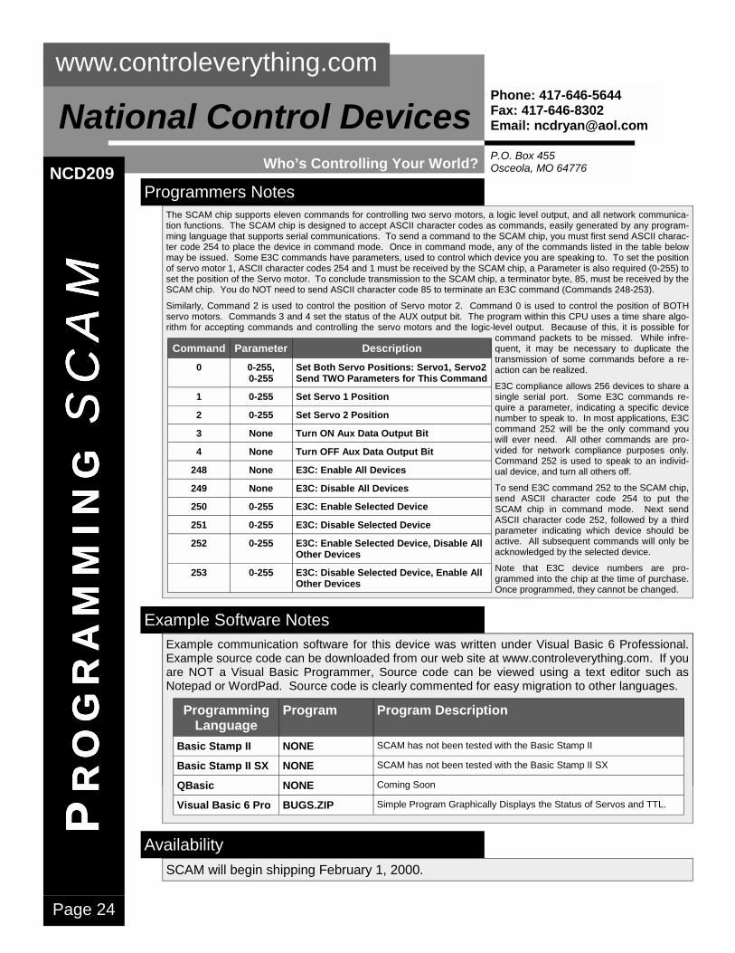
Example Software Notes Example communication software for this device was written under Visual Basic 6 Professional.
Programming Language
Program Program Description
Basic Stamp II NONE Anabug has not been tested with the Basic Stamp II
Basic Stamp II SX NONE Anabug has not been tested with the Basic Stamp II SX
QBasic NONE Coming Soon
Visual Basic 6 Pro AB.ZIP Simple Program Graphically Displays the Status of all 5 Inputs
Availability SCAM will begin shipping February 1, 2000.
Example Software Notes Example communication software for this device was written under Visual Basic 6 Professional. Example source code can be downloaded from our web site at www.controleverything.com. If you are NOT a Visual Basic Programmer, Source code can be viewed using a text editor such as Notepad or WordPad. Source code is clearly commented for easy migration to other languages.
Programming Language
Program Program Description
Basic Stamp II NONE SCAM has not been tested with the Basic Stamp II
Basic Stamp II SX NONE SCAM has not been tested with the Basic Stamp II SX
QBasic NONE Coming Soon
Visual Basic 6 Pro BUGS.ZIP Simple Program Graphically Displays the Status of Servos and TTL.
The SCAM chip supports eleven commands for controlling two servo motors, a logic level output, and all network communica-tion functions. The SCAM chip is designed to accept ASCII character codes as commands, easily generated by any program-ming language that supports serial communications. To send a command to the SCAM chip, you must first send ASCII charac-ter code 254 to place the device in command mode. Once in command mode, any of the commands listed in the table below may be issued. Some E3C commands have parameters, used to control which device you are speaking to. To set the position of servo motor 1, ASCII character codes 254 and 1 must be received by the SCAM chip, a Parameter is also required (0-255) to set the position of the Servo motor. To conclude transmission to the SCAM chip, a terminator byte, 85, must be received by the SCAM chip. You do NOT need to send ASCII character code 85 to terminate an E3C command (Commands 248-253).
Similarly, Command 2 is used to control the position of Servo motor 2. Command 0 is used to control the position of BOTH servo motors. Commands 3 and 4 set the status of the AUX output bit. The program within this CPU uses a time share algo-rithm for accepting commands and controlling the servo motors and the logic-level output. Because of this, it is possible for
command packets to be missed. While infre-quent, it may be necessary to duplicate the transmission of some commands before a re-action can be realized.
E3C compliance allows 256 devices to share a single serial port. Some E3C commands re-quire a parameter, indicating a specific device number to speak to. In most applications, E3C command 252 will be the only command you will ever need. All other commands are pro-vided for network compliance purposes only. Command 252 is used to speak to an individ-ual device, and turn all others off.
To send E3C command 252 to the SCAM chip, send ASCII character code 254 to put the SCAM chip in command mode. Next send ASCII character code 252, followed by a third parameter indicating which device should be active. All subsequent commands will only be acknowledged by the selected device.
Note that E3C device numbers are pro-grammed into the chip at the time of purchase. Once programmed, they cannot be changed.
Command Parameter Description 0 0-255,
0-255 Set Both Servo Positions: Servo1, Servo2 Send TWO Parameters for This Command
1 0-255 Set Servo 1 Position
2 0-255 Set Servo 2 Position
3 None Turn ON Aux Data Output Bit
4 None Turn OFF Aux Data Output Bit
248 None E3C: Enable All Devices
249 None E3C: Disable All Devices
250 0-255 E3C: Enable Selected Device
251 0-255 E3C: Disable Selected Device
252 0-255 E3C: Enable Selected Device, Disable All Other Devices
253 0-255 E3C: Disable Selected Device, Enable All Other Devices

Page 25
A AAAP
PL
ICA
TIO
NP
PL
ICA
TIO
NP
PL
ICA
TIO
NP
PL
ICA
TIO
N S
CA
MS
CA
MS
CA
MS
CA
M
www.controleverything.com
P.O. Box 455 Osceola, MO 64776
National Control Devices Phone: 417-646-5644 Fax: 417-646-8302 Email: [email protected]
Who’s Controlling Your World? NCD209 Application Notes
The SCAM chip was designed to provide users with an easy way to control multiple hobby servo motors for camera positioning applications. The Servo CAMera (SCAM) can easily be integrated into large scale security system and is perfect for home/office security monitoring needs. Complete plans for this project can be found in the Feb. 2000 issue of Nuts & Volts magazine. In the diagram below, two SCAM chips are connected to a single RS-232 serial port.
Each SCAM chip has a different device number burned into the chip at the time of purchase. This device number allows 256 SCAM chips to share a single serial port. When ordering, you MUST specify a device number from 0-255.
DB9 Female: Solder SideConnect to any AvailableRS-232 Serial Port.
CR1: 8 MHz Ceramic ResonatorCenter Lead Connects to GroundNot Polarity Sensitive+5
SV1
SV2
DO
OSC
RSI
GND+5
22K
OSCCR1
+5
WHITEREDBLACK
WHITEREDBLACK
4.7K
2N2222
5 VoltRelay
220
220
+5
SV1
SV2
DO
OSC
RSI
GND+5
22K
OSCCR1
+5
WHITEREDBLACK
WHITEREDBLACK
4.7K
2N2222
5 VoltRelay
220
220
Long DistancesOK up to 3K Feet.
Chain 256 SCAMChips Together
SCAM DEVICE 0Device Number isProgrammed Into Chipat Time of Purchase
SCAM DEVICE 1Device Number isProgrammed Into Chipat Time of Purchase
SCAM DEVICES 0-255Device Numbers AreProgrammed Into Chipat Time of Purchase
All Grounds Shown MUSTBe Connected Together
The SCAM Chip is E3C Compliant,Allowing Other Device Types, Up to256, to Share a Single Serial Port.
All Communication is9600 Baud, 8, N, 1.
+5
+5
+5
+5
Control 256 R
elays & 512 Servos
from a Single R
S-232 Serial Port

Page 26
B BBBY
TE
YT
EY
TE
YT
E B B B B
UG
SU
GS
UG
SU
GS
: ::: S
CA
M2
SC
AM
2S
CA
M2
SC
AM
2
www.controleverything.com
P.O. Box 455 Osceola, MO 64776
National Control Devices Phone: 417-646-5644 Fax: 417-646-8302 Email: [email protected]
Who’s Controlling Your World?
Device Description: NCD210
Recommended Usage This device is provided with programming examples for the following systems. If programming examples are not provided for the Basic Stamp, then it is NOT RECOMENDED for use with this device at this time. E3C Compliance allows 256 Devices to interface to a single serial port.
SCAM2 is a 8-pin preprogrammed microcontroller based on the PIC12C671/672 core, and is available in DIP and SOIC packages. SCAM2 is programmed to position three hobby servo motors using a command-based communication protocol. SCAM2 accepts RS-232 commands at 9600 baud and is E3C compliant, allowing user-control of 256 dif-ferent SCAM2 chips or other devices using a single RS-232 serial port.
QBasic Visual Basic 6 Pro Basic Stamp II Basic Stamp II SX E3C Compliance
Compatible Yes Compatible Compatible Yes
Example Device Wiring: NCD210 SCAM2, shown at left, is easily connected to the serial port of your computer using only a 22K Ohm resistor. SCAM2 requires a regulated +5 volt power supply. SCAM2 has two servo motor outputs. A 220 Ohm current limiting resistor should be connected between the output of the chip and servo motor as show in the diagram. An 8 MHz ceramic resonator is connected to the OSC lines of the SCAM2 chip. When power if first applied, all three motors are centered, and the processor waits for command packets while control-ling the servos. The program within this CPU uses a time share algorithm for accepting commands and positioning the servo motors. Because of this, it is possible for command packets to be missed. While infrequent, it may be neces-sary to duplicate the transmission of some commands be-fore a reaction can be realized.
DB9 Female: Solder SideConnect to any AvailableRS-232 Serial Port.+5
SV1
SV2
SV3
OSC
RSI
GND+5OSC
CR1
SERVO SERVO
+5
SERVOCR1: 8 MHz CeramicResonator. CenterLead Connects toGround. Not PolaritySensitive.
Device number 0-255programmed into thedevice at time ofpurchase.
Current Pricing in US Dollars: NCD210 Package Type Qty 1-9 Qty 10-25 Qty 26-100 Qty 101-1000
DIP CALL CALL CALL CALL
SOIC CALL CALL CALL CALL
NCD210
Current Pricing in US Dollars: NCD210 Package Type Qty 1-9 Qty 10-25 Qty 26-100 Qty 101+
DIP $10 $5.90 $5.10 MARKET PRICE
SOIC $11 $6.90 $6.10 MARKET PRICE
Pin Label Function 1 +5 Connect to Regulated +5 Supply
2,3 OSC 8 MHz Ceramic Resonator Connection
4 RSI RS-232 Data Input, 9600 bps, 8,N,1
5 SV3 Servo Motor Control Output 3
6 SV2 Servo Motor Control Output 2
7 SV1 Servo Motor Control Output 1
8 GND Ground
Package Type Qty 1-9 Qty 10-25 Qty 26-100 Qty 101+ DIP $10 $9.00 $8.10 MARKET PRICE
SOIC $11 $10.00 $9.10 MARKET PRICE

Page 27
P PPPR
OG
RA
MM
ING
RO
GR
AM
MIN
GR
OG
RA
MM
ING
RO
GR
AM
MIN
G S
CA
M2
SC
AM
2S
CA
M2
SC
AM
2
www.controleverything.com
P.O. Box 455 Osceola, MO 64776
National Control Devices Phone: 417-646-5644 Fax: 417-646-8302 Email: [email protected]
Who’s Controlling Your World? NCD210 Programmers Notes
Example Software Notes Example communication software for this device was written under Visual Basic 6 Professional.
Programming Language
Program Program Description
Basic Stamp II NONE Anabug has not been tested with the Basic Stamp II
Basic Stamp II SX NONE Anabug has not been tested with the Basic Stamp II SX
QBasic NONE Coming Soon
Visual Basic 6 Pro AB.ZIP Simple Program Graphically Displays the Status of all 5 Inputs
Availability SCAM2 will begin shipping February 1, 2000.
Example Software Notes Example communication software for this device was written under Visual Basic 6 Professional. Example source code can be downloaded from our web site at www.controleverything.com. If you are NOT a Visual Basic Programmer, Source code can be viewed using a text editor such as Notepad or WordPad. Source code is clearly commented for easy migration to other languages.
Programming Language
Program Program Description
Basic Stamp II NONE SCAM2 has not been tested with the Basic Stamp II
Basic Stamp II SX NONE SCAM2 has not been tested with the Basic Stamp II SX
QBasic NONE Coming Soon
Visual Basic 6 Pro BUGS.ZIP Simple Program Graphically Displays the Status of all three servos.
The SCAM2 chip supports eleven commands for controlling three servo motors, a logic level output, and all network communica-tion functions. The SCAM2 chip is designed to accept ASCII character codes as commands, easily generated by any program-ming language that supports serial communications. To send a command to the SCAM2 chip, you must first send ASCII charac-ter code 254 to place the device in command mode. Once in command mode, any of the commands listed in the table below may be issued. Some E3C commands have parameters, used to control which device you are speaking to. To set the position of servo motor 1, ASCII character codes 254 and 1 must be received by the SCAM2 chip, a Parameter is also required (0-255) to set the position of the Servo motor. To conclude communication to the SCAM2 chip, a terminator byte, 85, must be received. You do NOT need to send ASCII character code 85 to terminate an E3C command (Commands 248-253). Similarly, Command 2 & 3 is used to control the position of Servo motors 2 & 3 respectively. Command 0 is used to control the position of ALL THREE servo motors, and requires 3 parameters (one for each motor).
The program within this CPU uses a time share algorithm for accepting commands and controlling the servo motors. Because of this, it is possible for command packets to be missed. While infrequent, it may be necessary to duplicate the transmission of
some commands before a reaction can be real-ized.
E3C compliance allows 256 devices to share a single serial port. Some E3C commands re-quire a parameter, indicating a specific device number to speak to. In most applications, E3C command 252 will be the only command you will ever need. All other commands are pro-vided for network compliance purposes only. Command 252 is used to speak to an individual device, and turn all others off.
To send E3C command 252 to the SCAM chip, send ASCII character code 254 to put the SCAM chip in command mode. Next send AS-CII character code 252, followed by a third pa-rameter indicating which device should be ac-tive. All subsequent commands will only be acknowledged by the selected device.
Note that E3C device numbers are pro-grammed into the chip at the time of purchase. Once programmed, they cannot be changed.
Command Parameter Description 0 0-255,
0-255, 0-255
Set Positions of ALL 3 Servos. Send THREE Parameters for This Command.
1 0-255 Set Servo 1 Position
2 0-255 Set Servo 2 Position
3 0-255 Set Servo 3 Position
248 None E3C: Enable All Devices
249 None E3C: Disable All Devices
250 0-255 E3C: Enable Selected Device
251 0-255 E3C: Disable Selected Device
252 0-255 E3C: Enable Selected Device, Disable All Other Devices
253 0-255 E3C: Disable Selected Device, Enable All Other Devices

Page 28
B BBBY
TE
YT
EY
TE
YT
E B B B B
UG
SU
GS
UG
SU
GS
: ::: B BBB
ITA
BU
GIT
AB
UG
ITA
BU
GIT
AB
UG
3 333
www.controleverything.com
P.O. Box 455 Osceola, MO 64776
National Control Devices Phone: 417-646-5644 Fax: 417-646-8302 Email: [email protected]
Who’s Controlling Your World?
Device Description: NCD220
Recommended Usage This device is provided with programming examples for the following systems. If programming examples are not provided for the Basic Stamp, then it is NOT RECOMENDED for use with this device at this time. E3C Compliance allows 256 Devices to interface to a single serial port.
Bitabug3 is a 8-pin preprogrammed microcontroller based on the PIC12C671/672 core, and is available in DIP and SOIC packages. Bitabug3 was designed to provide 3 TTL outputs from an RS-232 serial port. Bitabug3 is an enhancement of Bitabug2 by adding E3C compliance, allowing 256 devices to share a single RS-232 serial port. Bitabug3 does not act as a 3-bit serial to parallel converter like the Bitabug2. Instead, output lines are completely command driven using simple E3C structured commands. Unlike the Bitabug2, Bitabug3 uses a command set for controlling each output individually or all outputs simultaneously. A customer-selected E3C device number of 0-255 must be programmed into the chip at the time of purchase.
QBasic Visual Basic 6 Pro Basic Stamp II Basic Stamp II SX E3C Compliance
Compatible Yes Compatible Compatible Yes
Example Device Wiring: NCD211 Bitabug3, shown at left, is easily connected to the serial port of your computer using only a 22K Ohm resistor. Bitabug3 requires a regu-lated +5 volt power supply. Bitabug3 has three TTL/CMOS (0/+5 volt) outputs, which are driven under computer control. Bitabug3 is shown with its digital outputs connected to three LEDs. When power is applied, Bitabug3 waits for E3C compliant commands for controlling the outputs on up to 256 chips. Note that an E3C device number of 0-255 must be programmed into the chip at the time of purchase.
DB9 Female: Solder SideConnect to any AvailableRS-232 Serial Port. 1K x 3
+5
RSI
DO0
DO1
DO2
OSC
OSC
GND+522K
4 MHz
NCD220
Pin Label Function 1 +5 Connect to Regulated +5 Supply
2, 3 OSC 4 MHz Ceramic Resonator
4 RSI RS-232 Data Input, 9600 bps, 8,N,1
5 DO2 Digital Output 3
6 DO1 Digital Output 2
7 DO0 Digital Output 1
8 GND Ground
Current Pricing in US Dollars: NCD220 Package Type Qty 1-9 Qty 10-25 Qty 26-100 Qty 101+
DIP $10 $9.00 $8.10 MARKET PRICE
SOIC $11 $10.00 $9.10 MARKET PRICE

Page 29
P PPPR
OG
RA
MM
ING
RO
GR
AM
MIN
GR
OG
RA
MM
ING
RO
GR
AM
MIN
G B BBB
ITA
BU
GIT
AB
UG
ITA
BU
GIT
AB
UG
3 333
www.controleverything.com
P.O. Box 455 Osceola, MO 64776
National Control Devices Phone: 417-646-5644 Fax: 417-646-8302 Email: [email protected]
Who’s Controlling Your World? NCD220
Example Software Notes Example communication software for this device was written under Visual Basic 6 Professional.
Programming Language
Program Program Description
Basic Stamp II NONE Anabug has not been tested with the Basic Stamp II
Basic Stamp II SX NONE Anabug has not been tested with the Basic Stamp II SX
QBasic NONE Coming Soon
Visual Basic 6 Pro AB.ZIP Simple Program Graphically Displays the Status of all 5 Inputs
Availability Bitabug3 will begin shipping March 1, 2000.
Example Software Notes Example communication software for this device was written under Visual Basic 6 Professional. Example source code can be downloaded from our web site at www.controleverything.com. If you are NOT a Visual Basic Programmer, Source code can be viewed using a text editor such as Notepad or WordPad. Source code is clearly commented for easy migration to other languages.
Programming Language
Program Program Description
Basic Stamp II NONE Bitabug3 is compatible with the Basic Stamp II
Basic Stamp II SX NONE Bitabug3 is compatible with the Basic Stamp II SX
Visual Basic 6 Pro BUGS.ZIP Simple Program Graphically Controls the Status of all 3 Outputs
Programmers Notes Bitabug3 supports 13 commands for controlling 3 TTL outputs bits and controlling all network functions. Bitabug3 is de-signed to accept numeric ASCII character codes from 0 to 255, easily generated by any programming language that sup-ports serial communications. To send a command to Bitabug3, you must first send ASCII character code 254 to place the device in command mode. Once in command mode, any of the commands listed in the table below may be issued. Some E3C commands have parameters, used to control which device you are speaking to. To turn on output DO1, ASCII char-acter codes 254 and 4 must be received by the Bitabug3. To turn off output DO1, send ASCII character codes 254 and 1. It is also possible to set all three outputs bits by sending ASCII character codes 254, 6, and a value from 0 to 7. 0 turns all outputs off, 7 turns all outputs on, every number in between is written to the outputs in its binary equivalent value. E3C compliance allows 256 devices to share a single serial port. Six commands are used to select which devices are ac-tive. Some E3C commands require a parameter, indicating a specific device number to speak to. In most applications, E3C command 252 will be the only command you will ever need. Command 252 is used to speak to an individual device, and turn all others off. This is what we call the “device selector” command. It is used to select a device from 0-255.
Note that E3C device numbers are pro-grammed into the chip at the time of pur-chase. Once programmed, they cannot be changed. To send E3C command 252 to the Bitabug3, send ASCII character code 254 to put the Bitabug3 in command mode. Next send AS-CII character code 252, followed by a third Parameter indicating which device should be active. All subsequent commands will only be acknowledged by the selected device. Other E3C commands allow you to control multiple devices simultaneously. Any E3C compliant devices may share a single serial port in any combination.
Command Parameter Description 0, 1, 2 None Turn Off Outputs 1, 2, & 3 respectively.
3, 4, 5 None Turn On Outputs 1, 2, & 3 respectively.
6 0-7 Write Byte (0-7) to all outputs at once.
248 None E3C: Enable All Devices
249 None E3C: Disable All Devices
250 0-255 E3C: Enable Selected Device
251 0-255 E3C: Disable Selected Device
252 0-255 E3C: Enable Selected Device, Disable All Other Devices
253 0-255 E3C: Disable Selected Device, Enable All Other Devices

Page 30
J JJJO
YO
YO
YO
YS SSS
CA
MC
AM
CA
MC
AM
SC
AM
SC
AM
SC
AM
SC
AM
C C C CO
NT
RO
LL
ER
ON
TR
OL
LE
RO
NT
RO
LL
ER
ON
TR
OL
LE
R
www.controleverything.com
P.O. Box 455 Osceola, MO 64776
National Control Devices Phone: 417-646-5644 Fax: 417-646-8302 Email: [email protected]
Who’s Controlling Your World?
Device Description: NCD219 NCD212 (JOYSCAM) is a 18-pin preprogrammed microcontroller based on the PIC12C672 core, and is available in DIP and SOIC packages. The JSCAM chip encodes position information from an analog joystick and outputs data packets that are readable by the SCAM chip (ND209), effectively providing a joystick interface for the SCAM chip. Optionally, a computer or Basic Stamp can be used to select which SCAM chip is receiving joystick data packets, as shown in the diagram below.
Example Device Wiring: NCD219 The JOYSCAM chip is used to send joystick-generated data packets to the SCAM chip as shown in the diagram. Option-ally, a computer can be con-nected for selecting which SCAM chip will be controlled by the JO-YSCAM chip.
+5
DigitalInput
RSO
SVP1
SVP2
OSC
DI
OSC
GND+5
Pot Inputs 1 & 2
DB9 Female: Solder SideConnect to any AvailableRS-232 Serial Port.
+5
SV1
SV2
DO
OSC
RSI
GND+5OSC
CR2
Device Number 0-255 ProgrammedInto Device at Time of Purchase
CR1: 4 MHz Ceramic ResonatorCR2: 8 MHz Ceramic ResonatorCenter Lead Connects to GroundNot Polarity Sensitive
Logic Level Output
SERVO SERVO
+5
CR1
Pin Label Function 1 +5 +5 Volt Regulated Power Supply
2, 3 OSC 4 MHz Ceramic Resonator
4 DI Digital Input
5 SVP2 Potentiometer Input for Controlling Servo Motor 2
6 SVP1 Potentiometer Input for Controlling Servo Motor 1
7 RSO RS-232 Data Packet Output for SCAM Chip
8 GND Power Supply Ground
NCD219
Current Pricing in US Dollars: NCD219 Package Type Qty 1-9 Qty 10-25 Qty 26-100 Qty 101+
DIP $10 $5.90 $5.10 MARKET PRICE
SOIC $11 $6.90 $6.10 MARKET PRICE

Page 31
AC
PA
CP
AC
PA
CP
S SSS: :::
VU
MV
UM
VU
MV
UM
ET
ER
ET
ER
ET
ER
ET
ER
www.controleverything.com
P.O. Box 455 Osceola, MO 64776
National Control Devices Phone: 417-646-5644 Fax: 417-646-8302 Email: [email protected]
Who’s Controlling Your World?
Device Description: NCD301 NCD301 (VUM) is a 18-pin preprogrammed microcontroller based on the PIC16C715 core, and is available in DIP and SOIC packages. VUM is a Stereo LED VU Meter Display Driver capable of driving 2 banks of 10 LEDs. The VUM chip supports 3 user-selectable display patterns: Dot, Bar, and Peak Hold & Fall. In Dot mode, an LED for each channel bounces up and down based on the level of the incoming signal. In Bar mode, a bar graph raises and lowers. In Peak Hold and Fall Mode (default), an LED stays lit, indicating the peak for each channel. The LED then falls off the bottoms of the display unless it is “Pushed” back up by the incoming signal. The VUM chip is unparalleled in capabilities and simplic-ity, and offers aggressive pricing in OEM quantities.
Example Device Wiring: NCD301 The VUM Chip, shown at left, drives 2 banks of 10 LEDs. The BANK output rapidly pulses, selecting which bank of 10 LEDs is driven by use of two 2N2222 transistors. The BANK output is an open collector sig-nal and MUST be tied high with a 220 Ohm resistor as shown in the schematic. Bank switching is extremely fast and is visually undetectable. An internal math scaler is adjusted by the Sensi-tivity Adjustment potentiometer, mathematically adjusting the response scale of the LEDs. The VU Meter chip, as shown, should only be used with line level audio signals (+/- 5 Volts MAX), and should not be con-nected to the Speaker Output of a stereo system without addi-tional protection electronics. Jumpers J1 and J2 select the Dot/Bar/Peak Hold display mode of the VUM chip. Display MODE is set when power is first applied to the chip. During op-eration, changing these jump-ers will have no effect until the next time power is applied. The
default display mode shows a bar graph that raises from the bottom of the display to the top based on the level of the incoming audio signal. The peak level is held by a single LED, which begins to fall soon after the in-coming signal falls. Subsequent incoming signals may “Push” the peak hold LED up the scale. The VU Chip is not strictly limited to audio applica-tions. It is ideally suited for gauges in industrial and automotive applica-tions, battery monitoring circuits, as well as simple temperature and light level monitoring.
RIGHTLED10
1K x 10
2N2222x 2
.001 uF x 2DigiKey Part: P4551
RIGHT
LEFT+5
+5
220Ohm
+5
+5 OSCOSC = 4 MHz
4.7K
10K POT
+5
J1
J2
2
3
4
5
6
7
8
9
18
17
16
15
14
13
12
11
10
1
LEFTLED10
SensitivityAdjustment
Current Pricing in US Dollars: NCD301 Package Type Qty 1-9 Qty 10-25 Qty 26-99 Qty 100+
DIP $16 $13 $10 MARKET PRICE
SOIC $17 $14 $11 MARKET PRICE
Pin Label Function 1 RIGHT Right Channel Audio In
2 LEFT Left Channel Audio In
3 BANK LED Bank Driver Output
4, 14 +5 +5 Volt Regulated Power Supply
5 GND Power Supply Ground
6, 7 LMS LED Driver, Mode Selector
8-13, 17 LED LED Display Driver Outputs
15, 16 OSC Ceramic Resonator Connection
18 LSENS LED 10 Driver, Sensitivity Adjust
NCD301
J1 J2 Display Mode Removed Removed Bar with Peak Hold and Fall
Installed Removed DOT Mode
Removed Installed BAR Mode
Installed Installed Bar with Peak Hold and Fall

Page 32
AC
PA
CP
AC
PA
CP
S SSS: :::
VU
MV
UM
VU
MV
UM
ET
ER
ET
ER
ET
ER
ET
ER
2 222
www.controleverything.com
P.O. Box 455 Osceola, MO 64776
National Control Devices Phone: 417-646-5644 Fax: 417-646-8302 Email: [email protected]
Who’s Controlling Your World?
Device Description: NCD302 NCD302 (VUM2) is a 18-pin preprogrammed microcontroller based on the PIC16C715 core, and is available in DIP and SOIC packages. VUM2 is a single channel 20 LED VU Meter Display Driver capable of driving 20 LEDs. The VUM2 chip supports 3 user-selectable display patterns: Dot, Bar, and Peak Hold & Fall. In Dot mode, an LED for each channel bounces up and down based on the level of the incoming signal. In Bar mode, a bar graph raises and lowers. In Peak Hold and Fall Mode (default), an LED stays lit, indicating the peak for each channel. The LED then falls off the bottoms of the display unless it is “Pushed” back up by the incoming signal. The VUM chip is unparalleled in capabilities and simplic-ity, and offers aggressive pricing in OEM quantities.
Example Device Wiring: NCD302 The VUM2 Chip, shown at left, drives 20 LEDs separated into two banks based on the signal strength of a single input. The VUM2 is electrically identical to the NCD301 (VUM) chip with the exception of PIN 1, which is not used on this device. The BANK output rapidly pulses, selecting which bank of 10 LEDs is driven by use of two 2N2222 transistors. The BANK output is an open col-lector signal and MUST be tied high with a 220 Ohm resistor as shown in the schematic. Bank switching is extremely fast and is visually undetectable. An internal math scaler is adjusted by the Sensitivity Adjustment potenti-ometer, mathematically adjusting the response scale of the LEDs. The VU Meter chip, as shown, should only be used with line level audio signals (+/- 5 Volts MAX), and should not be con-nected to the Speaker Output of a stereo system without addi-tional protection electronics. Jumpers J1 and J2 select the Dot/Bar/Peak Hold display mode of the VUM chip. Display MODE is set when power is first applied to the chip. During operation,
changing these jumpers will have no effect until the next time power is applied. The default display mode shows a bar graph that raises from the bottom of the display to the top based on the level of the incoming audio signal. The peak level is held by a single LED, which begins to fall soon after the incoming sig-nal falls. Subsequent incoming signals may “Push” the peak hold LED up the scale. The VU Chip is not strictly limited to audio applications. It is ideally suited for gauges in industrial and automotive applications, battery monitoring circuits, as well as simple temperature and light level monitoring.
LED20
1K x 10
2N2222x 2
.001 uFDigiKey Part: P4551
MONOAudio IN
+5
+5
220Ohm
+5
+5 OSCOSC = 4 MHz
4.7K
10K POT
+5
J1
J2
2
3
4
5
6
7
8
9
18
17
16
15
14
13
12
11
10
1
LED10SensitivityAdjustment
LED1 LED11
Current Pricing in US Dollars: NCD302 Package Type Qty 1-9 Qty 10-25 Qty 26-99 Qty 100+
DIP $16 $13 $10 MARKET PRICE
SOIC $17 $14 $11 MARKET PRICE
Pin Label Function 1 NC No Connection
2 LEFT Left Channel Audio In
3 BANK LED Bank Driver Output
4, 14 +5 +5 Volt Regulated Power Supply
5 GND Power Supply Ground
6, 7 LMS LED Driver, Mode Selector
8-13, 17 LED LED Display Driver Outputs
15, 16 OSC Ceramic Resonator Connection
18 LSENS LED 10 Driver, Sensitivity Adjust
NCD302
J1 J2 Display Mode Removed Removed Bar with Peak Hold and Fall
Installed Removed DOT Mode
Removed Installed BAR Mode
Installed Installed Bar with Peak Hold and Fall

Page 33
Item Qty Part Description Price Total
1
2
3
4
5
6
7
8
9
10
11
12
13
14
15
16
17
18
Order Form National Control Devices Shipping Address:
NAME
CO.
ADRS
ADRS
CITY
STATE
PHONE
ZIP
Billing Address: NAME
CO.
ADRS
ADRS
CITY
STATE
PHONE
ZIP
Payment:
VISA MC
NUM.
EXP.
CHECK M.O.
WIRE PO:
WWW.CONTROLEVERYTHING.COM
P.O. Box 455 Osceola, MO 64776 Phone: (417) 646-5644 FAX: (417) 646-8302
TOTAL Shipping Method:
UPS GROUND UPS 3-DAY UPS 2-DAY UPS OVERNIGHT UPS INTERNATIONAL US Priority Mail MAIL
$7.00 Minimum Shipping Charge. Actual Shipping Costs will be Added to
Total. Contact Us for Quote.

Contact Ryan Sheldon at (404) 244-2432, Cellular: (404) 307-5386, or e-mail [email protected]
National Control Devices offers a complete line of preprogrammedmicrocontrollers for a variety of embedded applications. Our microcontrollershave found their way in embedded systems all over the world. And for thepast 3 year, our customers have reported reliable in-service operation.
Industrial customers choose NCD preprogrammed micros because they arealways available, always reliable, and always the most powerful.
Prices include ceramic resonator.
1-25/$10 ea.26-99/$8.50 ea.100-up/call for current pricing.
Addressable Serial-to-Parallel ConverterThe NCD-101 series preprogrammed microcontrollerswere designed to perform high-speed serial-to-parallelconversion from a standard RS-232 data source. Baudrate is determined by the speed of the ceramic resona-tor attached to the microcontroller.
Up to 7 NCD-101 can be attached to a single RS-232 se-rial port providing a total 56 individually addressableoutput bits. The NAME jumpers N1, N2, and N3 deter-mine its address on the serial port. When all name jump-ers are installed, the NCD-101 performs a raw serial-to-parallel conversion.
The NCD-101 offers three command modes for commu-nication. These commands can be issued from any ter-minal program using 8 data bits and 1 stop bit.
Turn a Pin ON:Format: <NAME>N<PIN NUMBER><RETURN>Example: 0N3<RETURN>Action: Tell NCD-101 named 0 to turn on pin 3.
Turn a Pin OFF:Format: <NAME>F<PIN NUMBER><RETURN>Example: 6F3<RETURN>Action: Tell NCD-101 named 6 to turn off pin 3.
Output a BYTE:Format: <NAME>F<PIN NUMBER><RETURN>Example: 3P1<RETURN>Action: Tell NCD-101 named 3 to send byte 1.
Example: 3P0<RETURN>Action: Tell NCD-101 named 3 to send byte 0.
ASCII INPUT
Example below shows how easy it is to chain several NCD-101s to a singleRS-232 serial port. Note that RS-232 ground MUST share the ground ofthe circuit. Also note that each NCD-101 should be set to a different name.
To More NCD-101s.
Example Shows 24 Output Bits from a Single RS-232 Serial Port.
CR1 is a ceramic resonator. Using dif-ferent ceramic resonators changes thespeed in which the microprocessor func-tions. A crystal can be used to substi-tute the ceramic resonator.
Crystals are considered more reliable interms of their timing characteristics, butgreater accuracy is NOT needed in thisapplication. Ceramic resonators workwith 100% reliability, have built-in capaci-tors, and require less board space.
ASCII INPUT
+5
22K
10K x 3
N3
N2
N1
CR
1
DO
0
DO
1
DO
2
DO
3
DO
4
DO
5
DO
6
DO
7
8-Bit ParallelOutput
NC
D-1
01
PIC
16
C5
4A
NAME N3 N2 N1
0 0 0 0
1 0 0 1
2 0 1 0
3 0 1 1
4 1 0 0
5 1 0 1
6 1 1 0
NONE 1 1 1
CR1 BAUD
4 MHz 9600
2 MHz 4800
1 MHz 2400
500 KHz 1200
1 - Install Jumper0 - Remove Jumper

Contact Ryan Sheldon at (404) 244-2432, Cellular: (404) 307-5386, or e-mail [email protected]
Prices include ceramic resonator.
1-25/$10 ea.26-99/$8.50 ea.100-up/call for current pricing.
ASCII INPUT
+5
22K
10K x 2
N2
N1
CR
1
DI0
DI1
DI2
DI3
DI4
DI5
DI6
DI78-Bit Parallel
Input
NC
D-1
02
PIC
16
C5
4A
ASCII OUTPUT
Addressable Parallel-to-Serial EncoderThe NCD-102 series preprogrammed microcontrollerswere designed to perform high-speed parallel-to-serialencoding from a standard RS-232 data source. Baud rateis determined by the speed of the ceramic resonator at-tached to the microcontroller.
Up to 4 NCD-102 can be attached to a single RS-232 se-rial port providing a total 32 input bits. The NCD-102 is apolled device operating in a "speak when spoken to"mode. The NAME jumpers N1 and N2 determine its iden-tity on the serial port. When a valid name and carriagereturn is received, the NCD-102 reads the current statusof the 8 inputs and replies with a byte of data.
Turn a Pin ON:Format: <NAME><RETURN>Example: A<RETURN>Action: Tell NCD-102 named A to read inputs.
Will reply with a byte of data.
CR1 BAUD
4 MHz 9600
2 MHz 4800
1 MHz 2400
500 KHz 1200
CR1 is a ceramic resonator. Using dif-ferent ceramic resonators changes thespeed in which the microprocessor func-tions. A crystal can be used to substi-tute the ceramic resonator.
Crystals are considered more reliable interms of their timing characteristics, butgreater accuracy is NOT needed in thisapplication. Ceramic resonators workwith 100% reliability, have built-in capaci-tors, and require less board space.
ASCII INPUT
ASCII OUTPUTConnecting several NCD-102s is easy, but remember, outputs must beORed together as shown below. Also note that each 102 should have itsown name. RS-232 ground must be shared with the ground of the circuitbelow.
NAME N2 N1
A 0 0
B 0 1
C 1 0
D 1 1
0 - Remove Jumper1 - Install Jumper
Above example shows 32 logic-level inputs attached to a single RS-232 port.
National Control Devices offers a complete line of preprogrammedmicrocontrollers for a variety of embedded applications. Our microcontrollershave found their way in embedded systems all over the world. And for thepast 3 year, our customers have reported reliable in-service operation.
Industrial customers choose NCD preprogrammed micros because they arealways available, always reliable, and always the most powerful.

Contact Ryan Sheldon at (404) 244-2432, Cellular: (404) 307-5386, or e-mail [email protected]
Prices include ceramic resonator.
1-25/$10 ea.26-99/$8.50 ea.100-up/call for current pricing.
REPEAT (+5)
+5
10K x 2
S2
S1
CR
1
NC
D-1
03
PIC
16
C5
4A
ASCII OUTPUT
10
K x 4
16 Key Keypad
0
2
1
3
4
6
5
7
8
:
9
;
<
>
=
?
S1 S2 ASCII OUTPUT
0 0 ASCII Characters 0 to 15
1 0 ASCII Characters 16 to 31
0 1 ASCII Characters 32 to 47
1 1 ASCII Characters 48 to 63
CR1 BAUD
4 MHz 9600
2 MHz 4800
1 MHz 2400
500 KHz 1200
CR1 is a ceramic resonator. Using dif-ferent ceramic resonators changes thespeed in which the microprocessor func-tions. A crystal can be used to substi-tute the ceramic resonator.
Crystals are considered more reliable interms of their timing characteristics, butgreater accuracy is NOT needed in thisapplication. Ceramic resonators workwith 100% reliability, have built-in capaci-tors, and require less board space.
ASCII Keypad Encoder ProcessorThe NCD-103 series microcontrollers were de-signed to provide the user with a convenient methodof sending data to a computer or microcontrollerin applications that do not need a full-size keyboard.
The NCD-103 sends out an ASCII character for eachkey that is pressed. Up to 4 character sets can beselected by changing the jumpers at S1 and S2 al-lowing a total of 64 characters to be transmittedfrom a single processor.
The NCD-103 also has a built-in REPEAT line. Whentied high (+5 volts), any key that is held will con-stantly be transmitted until the button is released.This feature is disabled by connecting the REPEATline to ground.
The NCD-103 permits easy interface to any indus-try standard matrix type keypads. In addition, theNCD-103 requires very few external componentsmaking it an ideal choice for a variety of embeddedapplications.
Note: Pins 10 to 13 are inputs. The 10K pull-downresistors are required for reliable operation.
0 - Remove Jumper1 - Install Jumper
National Control Devices offers a complete line of preprogrammedmicrocontrollers for a variety of embedded applications. Our microcontrollershave found their way in embedded systems all over the world. And for thepast 3 year, our customers have reported reliable in-service operation.
Industrial customers choose NCD preprogrammed micros because they arealways available, always reliable, and always the most powerful.

Contact Ryan Sheldon at (404) 244-2432, Cellular: (404) 307-5386, or e-mail [email protected]
Delay TimerThe NCD-104 serves as a user-adjustable de-lay timer suitable for power up or power downdelay applications. Using a 10-bit input, up to1024 delay times can be realized. In addition,three versions of the NCD-104 are available foryour timing requirements.
On bootup, the DELAY output line is held low.When a start pulse is received, the NCD-104waits the user selected duration then bringsthe delay output line high.
The CLEAR line must be tied high for normaloperation. To reset or interrupt the timer, tiethe CLEAR line low momentarily.
Prices include ceramic resonator.
1-25/$10 ea.26-99/$8.50 ea.100-up/call for current pricing.
User Selected Duration
Delay Output Level
Start Pulse CR1 is a 4MHz ceramic resonator. Acrystal and two capacitors can be usedto substitute the ceramic resonator.
Crystals should be used if your timingrequirements are critical. A ceramicresonator provides accurate timingwithin 1%. Use a crystal if yourappication cannot accept this deviation.
Version Time Unit Longest Interval
NCD-104A seconds 17 minutes, 3 seconds.
NCD-104B minutes 17 hours, 3 minutes.
NCD-104C hours 42 days, 15 hours.
Product Variations:Product Variations:Product Variations:Product Variations:Product Variations:
National Control Devices offers a complete line of preprogrammedmicrocontrollers for a variety of embedded applications. Our microcontrollershave found their way in embedded systems all over the world. And for thepast 3 year, our customers have reported reliable in-service operation.
Industrial customers choose NCD preprogrammed micros because they arealways available, always reliable, and always the most powerful.
START
CLEAR
+5
10K x 2
T9
T8
CR
1
NC
D-1
04
PIC
16
C5
4A
DELAY
10K x 8
T5
T4
T7
T6
T2
T3
T0
T1
+5 +5
+5
+5

Contact Ryan Sheldon at (404) 244-2432, Cellular: (404) 307-5386, or e-mail [email protected]
National Control Devices offers a complete line of preprogrammedmicrocontrollers for a variety of embedded applications. Our microcontrollershave found their way in embedded systems all over the world. And for thepast 3 year, our customers have reported reliable in-service operation.
Industrial customers choose NCD preprogrammed micros because they arealways available, always reliable, and always the most powerful.
Pulse StretcherThe NCD-105 serves as a user-adjustable pulsestretcher. The pulse stretcher is ideally suitedin a large number of automation applications.
Use in telephones to limit the length of conver-sations. Use in automatic doors to control thelength of time the door stays open. Use in se-curity lighting systems to light an area for a lim-ited amount of time if motion is detected.
The NCD-105 has 1024 user-definable dura-tions from 1 second to 17 minutes. The CLEARline should be tied high for normal operation.Tie low to reset or interrupt timing interval.
The NCD-105 waits for a pulse. When received,the user-defined timer begins its cycle. Dur-ing this time, the PULSE OUT line is high. ThePULSE OUT line falls low after the user definedduration has passed.
Once a pulse has been received on the PULSEIN line, the timer does not begin counting againif a second pulse is received. Use the CLEARline to interrupt or reset the timer.
PULSE IN
PULSE OUT
PULSE IN
CLEAR
+5
10K x 2
T9
T8
CR
1
NC
D-1
05
PIC
16
C5
4A
PULSE OUT
10K x 8
T5
T4
T7
T6
T2
T3
T0
T1
+5 +5
+5
+5
Prices include ceramic resonator.
1-25/$15 ea.26-99/$13.50 ea.100-up/call for current pricing.
CR1 is a 4MHz ceramic resonator. Acrystal and two capacitors can be usedto substitute the ceramic resonator.
Crystals should be used if your timingrequirements are critical. A ceramicresonator provides accurate timingwithin 1%. Use a crystal if yourappication cannot accept this deviation.
User-Defined Duration

Contact Ryan Sheldon at (404) 244-2432, Cellular: (404) 307-5386, or e-mail [email protected]
Prices include ceramic resonator.
1-25/$15 ea.26-99/$13.50 ea.100-up/call for current pricing.
ASCII OUT
ASCII IN
+5
10K x 20 to +5
CR
1
NC
D-1
06
PIC
16
C7
1
22KD
I1
N1
N2
+5D
I2
DI3
DO
1
DO
2
DO
3
DO
4
10K x 2
.1uF x 2
0 to +5
RS-232 A/D with Digital I/OThe NCD-106 is perhaps one of our most popu-lar RS-232 interface microcontrollers. TheNCD-106 offers dual unipolar 8-bit analog todigital converters, 3 digital inputs, and 4 digi-tal outputs.
This processor is used in a variety of controlapplications and is vdigi9ry useful on the benchtopfor a variety of experimental purposes.
Up to 4 NCD-106s can share a single RS-232serial port. Networking them together pro-vides a total of 8 A/Ds, 12 inputs, and 16 out-puts.
CommandsThe NCD-106 has five commands that it willrespond to with an RS-232 transmission.
Send Analog Input StatusSend Analog Input StatusSend Analog Input StatusSend Analog Input StatusSend Analog Input StatusFormat: <NAME>A<CHANNEL><RETURN>Example: pA1<RETURN>Action: Tell NCD-106 named p to read A
analog input 1.Will reply with a byte of data.
Send Digital Input StatusSend Digital Input StatusSend Digital Input StatusSend Digital Input StatusSend Digital Input StatusFormat: <NAME><RETURN>Example: p<RETURN>Action: Tell NCD-106 named p to read
digital inputs.Will reply with a byte of data.
Turn On a Digital OutputTurn On a Digital OutputTurn On a Digital OutputTurn On a Digital OutputTurn On a Digital OutputFormat: <NAME>N<RETURN>Example: pN1<RETURN>Action: Tell NCD-106 named p to turn on
output pin 1.
Turn Off a Digital OutputTurn Off a Digital OutputTurn Off a Digital OutputTurn Off a Digital OutputTurn Off a Digital OutputFormat: <NAME>F<RETURN>Example: pF1<RETURN>Action: Tell NCD-106 named p to turn off
output pin 1.
Output a Byte to Digital OutputsOutput a Byte to Digital OutputsOutput a Byte to Digital OutputsOutput a Byte to Digital OutputsOutput a Byte to Digital OutputsFormat: <NAME>P<BYTE><RETURN>Example: pP0<RETURN>Action: Tell NCD-106 named p to
send a byte of ASCII 0.Note that data bits will be truncated for ASCII values above 15.
NAME N2 N1
p 0 0
q 0 1
r 1 0
s 1 1
ADIN2
ADIN1
CR1 BAUD
4 MHz 9600
2 MHz 4800
1 MHz 2400
500 KHz 1200
CR1 is a ceramic resonator. Using dif-ferent ceramic resonators changes thespeed in which the microprocessor func-tions. A crystal can be used to substi-tute the ceramic resonator.
Crystals are considered more reliable interms of their timing characteristics, butgreater accuracy is NOT needed in thisapplication. Ceramic resonators workwith 100% reliability, have built-in capaci-tors, and require less board space.
0 - Remove Jumper1 - Install Jumper
National Control Devices offers a complete line of preprogrammedmicrocontrollers for a variety of embedded applications. Our microcontrollershave found their way in embedded systems all over the world. And for thepast 3 year, our customers have reported reliable in-service operation.
Industrial customers choose NCD preprogrammed micros because they arealways available, always reliable, and always the most powerful.

Contact Ryan Sheldon at (404) 244-2432, Cellular: (404) 307-5386, or e-mail [email protected]
Prices include ceramic resonator.
1-25/$15 ea.26-99/$13.50 ea.100-up/call for current pricing.
51 Ohm
+510K x 4
CR
1
NC
D-1
07
PIC
16
C5
4A
2N2222
100 uF
1K
+5
Infrared LED
+5
10K x 4
+
MOD
BAUD
S2
S1
COL2
COL3
COL4
COL1
ROW3
ROW2
ROW1
ROW4
0
2
1
3
4
6
5
7
8
:
9
;
<
>
=
?
S1 S2 ASCII OUTPUT
0 0 ASCII Characters 0 to 15
1 0 ASCII Characters 16 to 31
0 1 ASCII Characters 32 to 47
1 1 ASCII Characters 48 to 63
CR1 is a 4 MHz ceramic resonator.
ASCII Keypad IR TransmitterThe NCD-107 is nearly identical in functionwith the NCD-103. The NCD 107 was de-signed to provide the user with a convenientmethod of sending RS-232 data to a com-puter or microcontroller via infrared datatransmission.
The NCD-107 sends out a modulated ASCIIcharacter for each key that is pressed. Up to4 character sets can be selected by chang-ing the jumpers at S1 and S2 allowing a totalof 64 characters to be transmitted from asingle processor.
When the MOD jumper is installed, the NCD-107 modulates the IR LED at 32.7 KHz (whichis compatible with our IRTR infrared trans-ceiver). When removed, the IR LED is modu-lated at 40 KHz.
When the BAUD jumper is installed, the NCD-107 transmits data at 300 baud. When re-moved, data is transmitted at 1200 baud.
The NCD-107 transmits modulated ASCII RS-232 data which can be decoded using a $4.00infrared receiver module.
The NCD-107 permits easy interface to anyindustry standard matrix type keypads. In ad-dition, the NCD-107 requires very few exter-nal components making it an ideal choice fora variety of remote control applications.
We also offer a similar keypad data transmit-ter complete with a printed circuit board.Please see page 3 of this catalog for details.
Note: Pins 10 to 13 are inputs. The 10K pull-down resistors are required for reliable op-eration.
0 - Remove Jumper1 - Install Jumper
National Control Devices offers a complete line of preprogrammedmicrocontrollers for a variety of embedded applications. Our microcontrollershave found their way in embedded systems all over the world. And for thepast 3 year, our customers have reported reliable in-service operation.
Industrial customers choose NCD preprogrammed micros because they arealways available, always reliable, and always the most powerful.

Contact Ryan Sheldon at (404) 244-2432, Cellular: (404) 307-5386, or e-mail [email protected]
Prices include ceramic resonator.
1-25/$10 ea.26-99/$8.50 ea.100-up/call for current pricing.
Pulse StretcherThe NCD-108 serves as a user-adjustablepulse stretcher with thumb-wheel (TWA, B,C) inputs. The pulse stretcher is ideallysuited in a large number of automation ap-plications.
Use in telephones to limit the length of con-versations. Use in automatic doors to con-trol the length of time the door stays open.Use in security lighting systems to light anarea for a limited amount of time if motionis detected.
The NCD-108 is available in two versionsoffering from 1 second to 7 hours and 59minute pulse lengths. The CLEAR lineshould be tied high for normal operation.Tie low to reset or interrupt timing inter-val.
The NCD-108 waits for a pulse. When re-ceived, the user-defined timer begins itscycle. During this time, the PULSE OUT lineis high. The PULSE OUT line falls low afterthe user defined duration has passed.
Once a pulse has been received on thePULSE IN line, the timer does not begincounting again if a second pulse is re-ceived. Use the CLEAR line to interrupt orreset the timer.
The following table shows the logic levelsat the input pins when the thumbwheel isset to different positions.
National Control Devices offers a complete line of preprogrammedmicrocontrollers for a variety of embedded applications. Our microcontrollershave found their way in embedded systems all over the world. And for thepast 3 year, our customers have reported reliable in-service operation.
Industrial customers choose NCD preprogrammed micros because they arealways available, always reliable, and always the most powerful.
PULSE IN
PULSE OUT
User-Defined Duration
10K x 8
CR
1
NC
D-1
08
PIC
16
C5
4A
+52.2K
+5
+5 START
CLEAR
PULSE OUT
10K x 2
TWA
TWB
TWC
TWA1
TWA2
TWA4
TWA8
TWB4
TWB2
TWB1
TWC4
TWC2
TWC1
+5 +5
CR1 is a 4MHz ceramic resonator. Acrystal and two capacitors can be usedto substitute the ceramic resonator.
Crystals should be used if your timingrequirements are critical. A ceramicresonator provides accurate timingwithin 1%. Use a crystal if yourappication cannot accept this deviation.
1 2 4 8
0 1 1 1 1
1 0 1 1 1
2 1 0 1 1
3 0 0 1 1
4 1 1 0 1
5 0 1 0 1
6 1 0 0 1
7 0 0 0 1
8 1 1 1 0
9 0 1 1 0
Th
um
bw
he
el P
osi
tio
ns:
BCD ValuesVersion T.W. 3 T.W. 2 T.W. 1 Maximum Delay
NCD-108A minutes seconds x 10 seconds 7 minutes, 59 seconds
NCD-108B hours minutes x 10 minutes 7 hours, 59 minutes
Product Variations:Product Variations:Product Variations:Product Variations:Product Variations:

Contact Ryan Sheldon at (404) 244-2432, Cellular: (404) 307-5386, or e-mail [email protected]
Prices include ceramic resonator.
1-25/$10 ea.26-99/$8.50 ea.100-up/call for current pricing.
Addressable 4-bit Serial-to-ParallelConverter with Dual Strobe OutputsThe NCD-110 is the most common interface pro-cessor used in the NCD product line. The NCD-110 is fully RS-232 network compliant allowing upto 16 NCD devices to share a single RS-232 serialport in any combination.
Up to 16 NCD-110 interface processors can sharea single RS-232 serial port offering a total of 64output bits. Each NCD-110 can be interfaced witha CMOS 4099 converting its 4-bit output to an ad-dressable 8-bit output. This method provides upto 128 output bits from a single RS-232 serial port.
The NCD-110 also provides dual stobing for sim-plified interface to active high and active low logic.In addition, a BAUD pin allows you to easily selectbetween 1200 and 9600 baud. Active baud ratedetection allows the speed to be changed whilein operation.
The NCD-110 is actively used in NCD products forrelay control, video switching, SPI Microwire emu-lation, motor controllers, and stepper controllers.
The NCD-110 listens to the RS-232 port and onlyresponds if its range of characters is received.When set to address 0 (A0 to A3 removed), theNCD-110 will only output data if ASCII characters0 to 15 are received.
The BINARY ADDRESS shows the logic states of the address pins10 to 13. The NCD ADDRESS is the device number as seen in theNCD product software. PIN 10 to PIN 13 show the actual logicstates for addressing. The ASCII RANGE is the range of ASCIIcharacters the NCD-110 will respond to for a given address.
BinaryAddress
NCDAddress
Pin 10 Pin 11 Pin 12 Pin 13ASCIIRange
0000 0 Ground Ground Ground Ground 0-15
0001 1 +5 Ground Ground Ground 16-31
0010 2 Ground +5 Ground Ground 32-47
0011 3 +5 +5 Ground Ground 48-63
0100 4 Ground Ground +5 Ground 64-79
0101 5 +5 Ground +5 Ground 80-95
0110 6 Ground +5 +5 Ground 96-111
0111 7 +5 +5 +5 Ground 112-127
1000 8 Ground Ground Ground +5 128-143
1001 9 +5 Ground Ground +5 144-159
1010 10 Ground +5 Ground +5 160-175
1011 11 +5 +5 Ground +5 176-191
1100 12 Ground Ground +5 +5 192-207
1101 13 +5 Ground +5 +5 208-223
1110 14 Ground +5 +5 +5 224-239
1111 15 +5 +5 +5 +5 240-255
The example shown at right willprovide 12 output bits from asingle RS-232 serial port. Addi-tional NCD-110s can be added tothe chain providing up to 64 out-put bits.
Note that RS-232 ground mustshare logic ground in this applica-tion. Also note that each NCD-110should be set to a different NCDaddress. Please see the table tothe left for details.
Each ASCII RANGE (see table) has16 possible characters that can bereceived by the NCD-110. These16 characters are broken intotheir binary equivalent (from 0 to15) and written as data on the 4-bit output of the NCD-110.
Transmitting ASCII characters 0to 255 in sequence will cause eachNCD-110 to count from 0 to 15 inbinary. The NCD-110 set to ad-dress 0 will count first, respond-ing to ASCII characters 0 to 15.The NCD-110 set to address 15will count last, responding only toASCII characters 240 to 255.
RS-232ASCII Input
National Control Devices offers a complete line of preprogrammedmicrocontrollers for a variety of embedded applications. Our microcontrollershave found their way in embedded systems all over the world. And for thepast 3 year, our customers have reported reliable in-service operation.
Industrial customers choose NCD preprogrammed micros because they arealways available, always reliable, and always the most powerful.
To M
ore
NC
D-1
10
s
ASCII INPUT
+5
22K10KSTROBE +5
+5
CR
1
DO
0
DO
1
DO
2
DO
3
A0
A1
A2
A3
10K x 4
NC
D-1
10
PIC
16
C5
4A
BAUD
STROBE
CR1 is a 4 MHz Ceramic Resonator.