polar navigation by squadron leader k. c. maclure,...
TRANSCRIPT

P O L A R N A V I G A T I O N
By Squadron Leader K. C. Maclure, R.C.A.F.
Editorial Note: Aircraft flights to the North Pole, such as the regular U.S.A.F. “Ptarmigan” weather reconnaissance flights from Fairbanks, Alaska, are now routine operations. The. navigation of these and other long-range flights of the U.S.A.F., R.C.A.F., and R.A.F. into very high latitudes is based on a special system known as grid navigation, or more accurately, polar grid navigation.
References to this method of navigation have appeared in technical journals, and in the popular accounts of recent polar flights, but the original paper setting forth the ideas on which the present operational techniques are based, has not heretofore been published. Written in October 1941, while the author was on instructional duties at an R.A.F. navigation school in Canada, it remained as a classified document until the end of the war.
In May 1945 the north polar flights of the R.A.F. Lancaster “Aries” (the author being one of the crew) were carried out specifically to -test the pro- posed method. Since then it has come into general use, with minor modifica- tions between the Services.
With the permission of the R.A.F., the major part of the original paper, dealing with the measurement of direction in polar latitudes, is reproduced here. The portions omitted concern the design and use of “astrographs”, a type of navigation instrument which saw considerable use during the war, but is now considered obsolete.
I. THE PROBLEMS INVOLVED IN POLAR NAVIGATION
W HILE simple methods are now being used for air navigation in normal latitudes, the question of polar navigation has rarely arisen, and at
first sight it appears to offer a number of difficulties. It is the purpose of this paper to show that it can be simplified to a large extent.
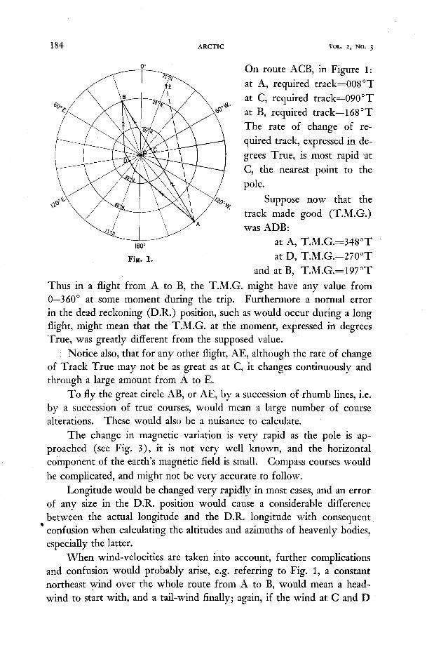
Before outlining the suggested methods, the various navigational problems which would be met in a trans-polar flight will be enumerated. T o understand them clearly consider the case of an aircraft required to fly from A (75”N., 140”W.) to B (80”N., 20”E.). This somewhat exaggerated case will best illustrate the points which will arise in any flight in these high latitudes. Figure 1 is a polar projection of the region, P representing the north pole and A and B the points of departure and destination respectively.
The great circle from A to B, is represented very closely on this projection by the straight line ACB. The distance is approximately 1,480 nautical miles.
183
184 AKCTIC VOL. 2 , NO. 3
0" On route ACB, in Figure 1:
at A, required track=008OT a t C, required track=090"T a t B, required track=168"T The rate of change of re- quired track, expressed in de- grees True, is most rapid at C, the nearest point to the pole.
Suppose now that the track made good (T.M.G.) was ADB:
180" a t A, T.M.G.=348"T '
Fig. 1. a t D, T.M.G.=27O0T and a t B, T.M.G.=197"T
Thus in a flight from A to B, the T.M.G. might have any value from 0-360" a t some moment during the trip. Furthermore a normal error in the dead reckoning (D.R.) position, such as would occur during a long flight, might mean that the T.M.G. at tlie moment, expressed in degrees True, was greatly different from the supposed value.
Notice also, that for any other flight, AE, although the rate of change of Track True may not be as great as a t C, it changes continuously and through a large amount from A to E.
T o fly the great circle AB, or AE, by a succession of rhumb lines, i.e. by a succession of true courses, would mean a large number of course alterations. These would also be a nuisance to calculate.
The change in magnetic variation is very rapid as the pole is ap- proached (see Fig. 3), it is not very well known, and the horizontal component of the earth's magnetic field is small. Compass courses would be complicated, and might not be very accurate to follow.
Longitude would be changed very rapidly in most cases, and an error of any size in the D.R. position would cause a considerable difference between the actual longitude and the D.R. longitude with consequent ' confusion when calculating the altitudes and azimuths of heavenly bodies,
especially the latter. When wind-velocities are taken into account, further complications
and confusion would probably arise, e.g. referring to Fig. 1, a constant northeast wind over the whole route from A to B, would mean a head- wind to start with, and a tail-wind finally; again, if the wind a t C and D
POLAR NAVIGATION 185
were approximately the same with regard to the aircraft’s general track from A to B say from relative bearing of 45”, it would nevertheless be a southeast wind a t C, and a northwest wind at D. Or, a constant wind- direction from A to E, with regard to the aircraft’s track, would be expressed as a great many different directions in degrees True, as the aircraft progressed,
In order to eliminate these confusing details from the work, and to provide the Navigator with a simple, quick and accurate method of navi- gating from any point in this region to any other point, irrespective of whether the pole is passed to the right or to the left of the track, or indeed whether the track passes directly over the pole, the following suggestions are put forward. They are divided into three sections: the first on the construction and use of a Polar Astrograph for use during arctic night, the second on the measurement of directions in polar regions, and the third on navigational methods during arctic “Day” and “Twilight.”
11. THE POLAR ASTROGRAPH
From approximately October 9 to March 5, the sun will be 6” or more below the horizon of an observer a t the North Pole. During this arctic night then, we shall presume that the navigator is able to plan a flight so that the stars will be visible. The question of a trans-polar flight by day, is discussed in a later section.
The simplest method of fixing the position of the aircraft would be by sextant observations of the stars in conjunction with a polar astrograph constructed along the lines of the regular astrograph, but somewhat simpler. This polar astrograph would consist of a projector which would throw the shadow of a set of intersecting star curves on the navigator’s chart, similar to the operation of the regular astrograph.
(Editorial Note: The description of the proposed instrument is omitted here. Since the date of this paper the astronomical tables used by air navigators for calculating altitudes and azimuths have been extended to the poles, and the astrograph is no longer in general use.)
111. MEASUREMENT OF DIRECTION IN POLAR REGIONS
Referring back to the introduction, it will be noticed that many of the difficulties involved in trans-polar navigation result from the rapid con- vergence of the meridians. For example, when flying directly over the pole, the course is changed through 180”; and a t the pole itself, every direction is south, or 180”T. This is, of course, just because the pole has been chosen as the reference point for directions on the earth. The choice
186 ARCTIC VOL. 2 , NO. 3
of another point on the earth's surface far removed from the pole, from which to measure directions while in polar regions, would solve a great many of the difficulties.
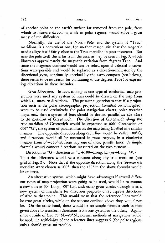
Normally, the use of the North Pole, and the system of "True" meridians, is a convenient one, for another reason, viz. that the magnetic needle aligns itself fairly close to the True meridian in most instances. But near the pole itself this is far from the case, as may be seen in Fig. 3, which illustrates approximately the magnetic variation from degrees True. And since the magnetic compass would not be relied upon if celestial observa- tions were possible and would be replaced as a direction-indicator by the directional gyro, continually checked by the astro compass (see below), there seems to be no reason for continuing to use degrees True for express- ing directions in these latitudes.
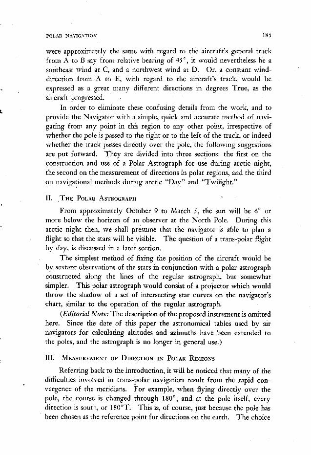
Grid Direction. In fact, as long as one type of conforinal map pro- jection were used any system of lines could be drawn on the map from which to measure directions. The present suggestion is that if a projec- tion such as the polar stereographic projection (zenithal orthomorphic) were to be used exclusively for polar navigation charts, polar weather maps, etc., then a system of lines should be drawn, parallel on the chart to the meridian of Greenwich. The direction of Greenwich along the true meridian of Greenwich would be expressed as 000" Greenwich or 000" "G", the system of parallel lines on the map being labelled in a similar manner. The opposite direction along each line would be called 180"G, and directions would all be measured in these regions, in a clockwise manner from 0" - 360"G, from any one of these parallel lines. A simple formula would connect directions measured on the two systems:-
Direction in "G=direction in "Tfl8O"Long. E. (or+Long. W.) Thus the difference would be a constant along any true meridian (see grid in Fig. 2) . Note that if the opposite direction along the Greenwich meridian were chosen as OOO", then the 180" in the above formula would be omitted.
An alternative system, which might have advantages if several differ- ent rypes of map projection were going to be used, would be to assume a new pole at 00" Long.-00" Lat. and, using great circles through it as a new system of meridians for direction purposes only, express directions relative to that point. This would mean that the reference lines would be true great circles, while on the scheme outlined above they would not be. On the other hand, there would be no simple formula such as that given above to transform directions from one system to the other. Again, since outside of Lat. 7S0N.-90"N., normal methods of navigation would be used, the artificiality of the reference lines suggested (for polar regions only) should cause no trouble.
POLAR NAVIGATION 187
Any other direction besides the direction of the meridian through Greenwich might be used, such as a meridian passing close to the north magnetic pole. This latter method would mean that the variation of the magnetic needle from this direction would'not be as large numerically as on the other system, but the advantage would be too slight to outweigh Longitude East Longitude West
0oO"G
t 0"
+ 18000
its disadvantages (see below). The same applies to the use of other meridians. For a particular flight, 'the required track from A to B could be used as a reference line, and all courses and wind-directions measured relative to it. But in case the route was changed, and for the use of weather maps, etc., a simple unchanging standard such as degrees ."G',' is considered better.
Fig. 2. The Greenwich Grid.
Great Circle Routes. Since on the stereographic projection, a straight line remesents verv closelv a meat circle. the great circle track from A

188 ARCTIC VOL. 2 , NO. 3
to B would .be represented as a single direction in degrees “G”. No alter- ation of course for convergency would be necessary.
Use of Astro Compass. As the magnetic compass is not likely to be very reliable in polar regions, steering courses by directional gyro (D.G.), with frequent checks by the astro compass, appears to be the best method. Referring back to Fig. 1, if it were required to fly from A to B, and if we assume for the moment that there were no wind, then a perfectly friction- less D.G. would enable the pilot to keep the aircraft on the great circle route from A to B (also ignoring the earth‘s rotation). Since the D.G. is not frictionless it would have to be checked a t regular intervals from bearings of the stars, taken with the astro compass.
It is considered that owing to the rapid change of longitude, and therefore rapid change of hour angle, that the most accurate method of using the astro compass, and the simplest, would be to use it in conjunction with the polar astrograph. The direction of the stars is, of course, at right-angles to the equal altitude circles, in the direction of increasing altitude, so that using the astro compass as a bearing plate, and taking azimuth and altitude from the astrograph, rather than latitude, local hour angle, and declination from the almanac, would be the best and easiest method.
Thus if the directional gyro did not precess, the grid course (Co. “G”) could be set on the D.G. at the outset, and would remain the same from A to B, except for changes in the wind-velocity, and the earth’s rotation. But owingio friction, the D.G. has to be checked continually and, as explained above, this could be done most easily with the astro compass, using it as a bearing plate, and taking the azimuth and altitude from the polar astrograph. The procedure followed would be to set the polar astrograph properly for time; then at the D.R. position on the chart, read the approximate altitude of one of the stars, and measure its direction or azimuth in degrees “G”. Setting this latter reading on the astro compass at the arrow labelled “True Bearing,” and setting the altitude on the declination scale, the astro compass would then be swung around until the star was sighted. The course in degrees “G” would then be read off the azimuth scale a t the lubber line. (Editorial Note: The astro- graph is no longer in general use, tabular methods of calculating altitude being adopted for all latitudes. Similarly current practice on polar flights is to set Lat., L.H.A., and dec. on the astro compass as in normal latitudes, thus obtaining Co.T., but then converting to Co.“G”, by simple formula as explained earlier in the paper, using exactly the same figure for longitude as used in calculation of local hour angle from Greenwich hour angle. “Assumed longitude” can be several degrees in error without affecting

POLAR NAVIGATION 189
accuracy of resulting Co.“G”.) Since the gyro precession owing to friction is much greater than that owing to the earth’s rotation, the latter can be ignored.
Referring to Fig. 2, it will be seen that an error of 100 miles or so, in the D.R. position would mean but a small error in the calculated (or measured) bearing of the star in degrees “G’. Consequently, when this bearing is set on the astro compass, as explained above, the resulting measurement of the course in degrees “G” is only slightly in error, the error being of about the same magnitude as would exist if the procedure were followed in normal latitudes. But it will also be observed that in high latitudes, if the bearing were measured in degrees True, an error in D.R. position of 100 miles might mean a considerable error in longitude, which would mean a considerable error in the calculated bearing of a star in degrees True, with the same error resulting in the measurement of the course in degrees True. Since the error, and the confusion which it would cause, results solely from the use of true north as a reference point for direction, it provides a strong argument for using degrees “G” rather than degrees True in these latitudes.
Measurement of W i n d Directions. In the first paragraphs of this paper, describing the problems of trans-polar navigation, it was pointed out that a constant wind speed from a constant direction in degrees True, means a continuously changing wind-velocity, relative to the required track. Conversely, a constant wind, relative to the desired track, is expressed as a wind blowing from a continuously changing direction in degrees True. Since the aircraft will only have to alter course due to change in wind when either the speed of the wind or its direction relative to required track changes, measurement of wind direction in degrees “G”, will overcome this problem also. Actually, the wind direction could be expressed relative to the required track AB, but this would not have the same advantages as always expressing it relative to the same direction, the meridian of Greenwich, i.e. in degrees “G”.
It is suggested then that the weather map for the region should have the “G” lines marked thereon, and the weather forecast for the route express wind directions in degrees “G”. By using the simple formula for changing True to Grid these directions could always be changed to degrees True when required, such as near the 75th parallel, where the polar chart would join the chart for lower latitudes.
Navigating from Lower Latitudes into Polar Regions. If an aircraft were flying from lower latitudes into polar regions it is suggested that the navigation be carried on in the usual manner, expressing directions in degrees True. until 75”N. is reached. Then. if the Dosition of,the aircraft
0 1

190 ARCTIC VOL. 2, NO. 3
were marked on the polar chart, and the required track laid down, naviga- tion from there on should be carried out by the scheme outlined above.
Measurement of Position. A rectangular system of expressing posi- tion could be superimposed on the chart, but this is not considered advis- able. Since tracks, distances, positions, etc., in air navigation, are mea- Longitude East Longitude West
Fig. 3. Lines of equal magnetic variation in degrees True. (Apply variation to C0.M. to obtain Co.T., i.e. positive variation=easterly variation).
sured on charts as a rule, and not calculated by traverse tables, a rectangular system would be more of a nuisance than it was worth. Moreover the ordinary system of expressing position by latitude and longitude would be necessary when the polar portion of a flight were joined to rhe non- polar portion. It is considered that the ordinary system of expressing positions by latitude and longitude should be retained for polar navigation.
Variation. Referring to Fig. 3 it will be noticed that the magnetic variation changes very rapidly near the pole, partly owing to the proximity of the magnetic pole, but also owing to the use of the north pole as the point from which directions are measured. It will be noticed that by
POLAR NAVIGATION 191
flying a small circle around the pole, k 0 degrees of “True” variation is passed through.
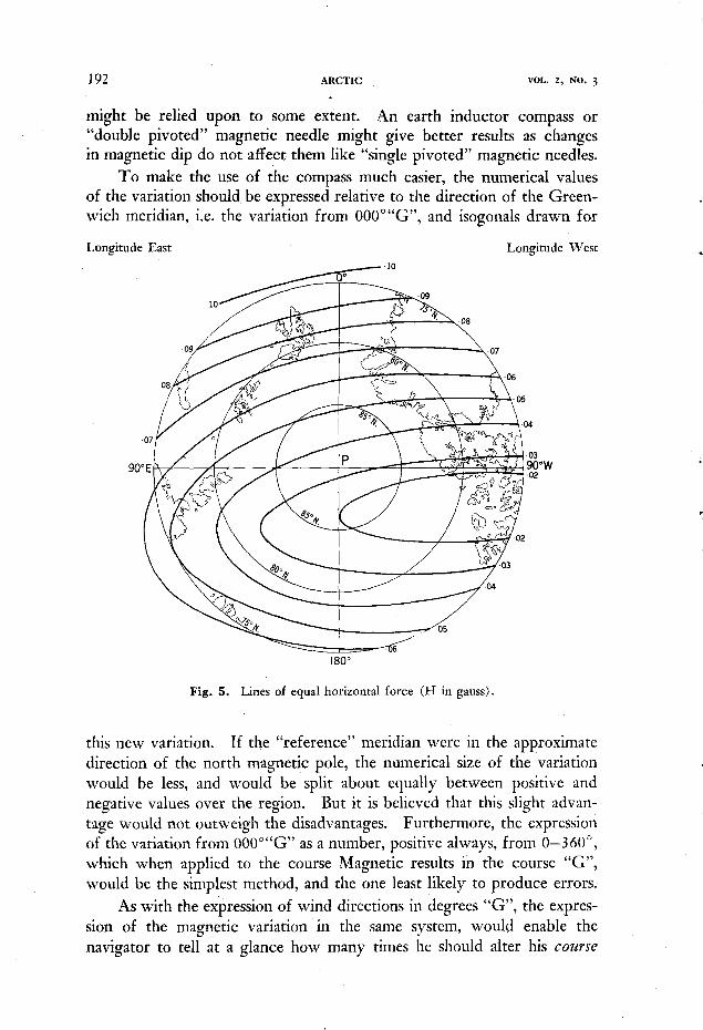
Fig. 5 shows approximately what the horizontal force of the earth’s magnetic field is likely to be. This map, like the specimen variation chart, Fig. 3, has been produced by extrapolating the curves for lower latitudes, taking into account the location of the north magnetic pole, and the
Longitude East Longitude West
0”
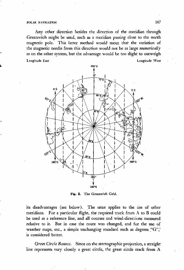
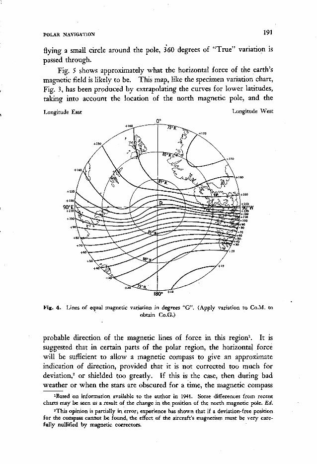
Fir. 4. Lines of equal magnetic variation in degrees “G’. (Apply variation to C0.M. to obtain Co.G.)
probable direction of the magnetic lines of force in this region1. It is suggested that in certain parts of the polar region, the horizontal force will be sufficient to allow a magnetic compass to give an approximate indication of direction, provided that it is not corrected too much for deviation,2 or shielded too greatly. If this is the case, then during bad weather or when the stars are obscured for a time, the magnetic compass
1Based on information available to the author in 1941. Some differences from recent charts may be seen as a result of the change in the position of the north magnetic pole. Ed.
2This opinion is partially in error; experience has shown that if a deviation-free position for the compass cannot be found, the effect of the aircraft’s magnetism must be very care- fully nullified by magnetic correctors.
a
192 ARCTIC VOL. 2, NO. 3
might be relied upon to some extent. An earth inductor compass or “double pivoted” magnetic needle might give better results as changes in magnetic dip do not affect them like “single pivoted” magnetic needles.
To make the use of the compass much easier, the numerical values of the variation should be expressed relative to the direction of the Green- wich meridian, i.e. the variation from 00O0“G”, and isogonals drawn for
Longitude East Longitude West
- - 3 3 180”
Fig. 5. Lines of equal horizontal force (H in gauss).
this new variation. If the “reference” meridian were in the approximate direction of the north magnetic pole, the numerical size of the variation would be less, and would be split about equally between positive and negative values over the region. But it is believed that this slight advan- tage would not outweigh the disadvantages. Furthermore, the expression of the variation from OOO”“G” as a number, positive always, from 0-3 60”, which when applied to the course Magnetic results in the course “G”, would be the simplest method, and the one least likely to produce errors.
As with the expression of wind directions in degrees “G”, the expres- sion of the magnetic variation in the same system, would enable the navigator to tell a t a glance how many times he should alter his couwe

POLAR NAVIGATION 193
Magnetic in order to fly from A to B (presuming he was using his magnetic compass).
Figure 4 shows approximately what the isogonals on the new system would look like. It will be noticed that the range of variation is not as great as on the old system (Fig. 3 ) , and that the isogonals are more nearly parallel, making the use of them considerably simpler.
IV. ARcnc DAY AND TWILIGHT NAVIGATION
For miscellaneous sights, which would include the sun, planets, moon, and odd stars with declinations between 10"s. and 30"N., the scheme proposed is to use a "Baker Machine" type of Astrograph, using 4 sets of curves for declinations 5"S., SON., 15"N. and 2S"N., respectively. (Editorial Note: Remainder of description of this instrument omitted here).
Watch Errors. (This applies to stars as well as sun). Since fixes from a correct sextant (no accel. error), but an incorrect watch, are correct as to latitude, but incorrect as to longitude being displaced east or west 15' of longitude for every minute of watch error, an error of 4 min. of watch time will cause a 1" error in the longitude of the fix, which is only 15 n.m. at Lat. 75"; 10 n.m. at Lat. SO", etc. Watch time could be recorded then to the nearest f minute, since errors of f minute of time would cause errors of less than 2 miles.
Rate of Change of Azimuth. It may be thought that near the pole the azimuth changes rapidly. If an aircraft is flying near the pole, the true azimuth would change rapidly, but on reference to Fig. 2 it will be seen that the azimuth in degrees "G" will change slowly. It is therefore out of the question to hope to obtain a running fix from successive sun observations.
Navigation during Arctic Twilight. At the North Pole, the sun is above the horizon for 6 months of the year, and below it for the remaining time. When it is 6" or more below the horizon, it is presumed that the stars would be used for navigation. During the "Day", single position lines would be obtained from the sun, and if the flights were planned so that the position lines from the sun were parallel to the track when nearing the destination, navigation using the sun alone would be quite satisfactory.
But during twilight, the planets or moon would probably be used as much as possible. The moon would be useful for varying periods of time each year, and Venus and Mars could be used a t times, depending on their declination. Saturn and Jupiter would be very useful, since they both have northerly declination a t the present time (October 1941) and will

194 ARCTIC VOL. 2, NO. 3
have for some years to come. Polaroid filters, and telescopic attachments for the bubble sextant would increase the usefulness of the stars.
Refraction. For the stars chosen for the polar astrograph, the astro- nomical refraction is not great, and has been allowed for in constructing the star curves. But while taking observations of the sun when it is very low, the correct amount of refraction is of considerable importance. Owing to the very dense atmosphere over the pole, special tables might have to be made for low altitude sights.
Summary
It is believed that the problem of navigation in polar regions would be greatly simplified by the following suggestions: (a) That during the arctic night, courses be flown by directional gyro, checking continually by observations with the astro compass of the stars selected for the astrograph, using the astro compass as a bearing plate, and obtaining the altitude and azimuth of the stars from the astrograph. (b) That all directions in polar regions (Lat. 75 O to 90°) be measured relative to a system of parallel lines drawn on a conformal polar projection (such as the stereographic), parallel to the meridian of Greenwich; that the direction towards Greenwich on its meridian be called OOOO"G' , and simi- larly on the system of parallels; that any other direction be measured from this direction, in a clockwise manner from 0°-360""G". (c) That weather maps, forecasts etc. use degrees "G" for the expression of direction in polar regions. (d) That isogonals be drawn on the charts, giving the magnetic variation as a positive number, from 0" to 360", which, by applying to the course Magnetic, will produce the course "G". (e) That positions continue to be measured in latitude and longitude in the normal manner.
No. 3 1 Air Navigation School, Royal Air Force, Port Albert, Ont., Canada, October 1941.