polarizability tensor retrieval for magnetic and plasmonic antenna
TRANSCRIPT

PAPER • OPEN ACCESS
Polarizability tensor retrieval for magnetic andplasmonic antenna designTo cite this article: Felipe Bernal Arango and A Femius Koenderink 2013 New J. Phys. 15 073023
View the article online for updates and enhancements.
You may also likeThe properties and design concepts ofphotonic directional couplers made ofphotonic crystal slabsChih-Hsien Huang, Jing-Nuo Wu, Po-YiLee et al.
-
IARD 2010: The 7th Biennial Conferenceon Classical and Quantum RelativisticDynamics of Particles and FieldsLawrence Horwitz, Bei-Lok Hu, Da-ShinLee et al.
-
Towards low- loss on-chip nanophotonicswith coupled graphene and silicon carbide:a reviewPatrick Rufangura, Thomas G Folland, ArtiAgrawal et al.
-
This content was downloaded from IP address 223.18.226.85 on 03/02/2022 at 07:12

Polarizability tensor retrieval for magnetic andplasmonic antenna design
Felipe Bernal Arango1 and A Femius KoenderinkAMOLF, Center for Nanophotonics, FOM Institute AMOLF, Science Park 104,1098-XG Amsterdam, The NetherlandsE-mail: [email protected]
New Journal of Physics 15 (2013) 073023 (20pp)Received 29 March 2013Published 9 July 2013Online at http://www.njp.org/doi:10.1088/1367-2630/15/7/073023
Abstract. A key quantity in the design of plasmonic antennas andmetasurfaces, as well as metamaterials, is the electrodynamic polarizabilityof a single scattering building block. In particular, in the current mergingof plasmonics and metamaterials, subwavelength scatterers are judged bytheir ability to present a large, generally anisotropic electric and magneticpolarizability, as well as a bi-anisotropic magnetoelectric polarizability. Thisbi-anisotropic response, whereby a magnetic dipole is induced through electricdriving, and vice versa, is strongly linked to the optical activity and chiralresponse of plasmonic metamolecules. We present two distinct methods toretrieve the polarizibility tensor from electrodynamic simulations. As a basisfor both, we use the surface integral equation (SIE) method to solve for thescattering response of arbitrary objects exactly. In the first retrieval method, weproject scattered fields onto vector spherical harmonics with the aid of an exactdiscrete spherical harmonic Fourier transform on the unit sphere. In the second,we take the effective current distributions generated by SIE as a basis to calculatedipole moments. We verify that the first approach holds for scatterers of anysize, while the second is only approximately correct for small scatterers. Wepresent benchmark calculations, revisiting the zero-forward scattering paradoxof Kerker et al (1983 J. Opt. Soc. Am. 73 765–7) and Alu and Engheta (2010 J.Nanophoton. 4 041590), relevant in dielectric scattering cancelation and sensorcloaking designs. Finally, we report the polarizability tensor of split rings, andshow that split rings will strongly influence the emission of dipolar single
1 Author to whom any correspondence should be addressed.
Content from this work may be used under the terms of the Creative Commons Attribution 3.0 licence.Any further distribution of this work must maintain attribution to the author(s) and the title of the work, journal
citation and DOI.
New Journal of Physics 15 (2013) 0730231367-2630/13/073023+20$33.00 © IOP Publishing Ltd and Deutsche Physikalische Gesellschaft

2
emitters. In the context of plasmon-enhanced emission, split rings can imbuetheir large magnetic dipole moment on the emission of simple electric dipoleemitters. We present a split ring antenna array design that is capable of convertingthe emission of a single linear dipole emitter in forward and backward beams ofdirectional emission of opposite handedness. This design can, for instance, findapplication in the spin angular momentum encoding of quantum information.
Contents
1. Introduction 22. Surface integral equation method and α-tensor retrieval 3
2.1. Multipole moments based on the projection onto vector spherical harmonics . . 62.2. Multipole moments based on effective currents . . . . . . . . . . . . . . . . . 72.3. Polarizability tensor retrieval . . . . . . . . . . . . . . . . . . . . . . . . . . . 8
3. Benchmark of vector spherical harmonics and effective current density α-retrieval 84. Polarizability retrieval applied to Kerker’s paradox of zero-forward scattering
spheres 105. Split ring polarizability 116. Single split ring as a magnetic dipole converter 147. Split ring array antenna 178. Conclusions 18Acknowledgments 19References 19
1. Introduction
Metallic and dielectric nanoscatterers currently enjoy a surge of interest in photonics, dueto the unusual optical properties that may be obtained through a suitable choice of materialand geometry. In plasmonics, it is well established that Ag and Au single nanospheres, rods,wires, pyramids, triangles, cubes, stars or core–shell particles, as well as oligomers andarrays of such objects have very distinct scattering resonances that can be used for opticalsensing, improvement of LEDs and solar cells, as well as plasmon-enhanced spectroscopyon the basis of large field enhancements near metals at the plasmon resonance [3–9]. Ina related development, the field of metamaterials uses metal split rings, loops as well asso-called cut-wire pairs to generate a strong collective magnetic response [10–12]. Theeffective magnetic permeability and electric permittivity that is achieved arises from thestrong electric and magnetic polarization obtained in each building block. Recently, thefields of plasmonics and metamaterials have come together in so-called ‘metasurfaces’, wherenon-identical subwavelength resonant scatterers are organized in a plane at subwavelengthdistances, in order to achieve arbitrary phase and amplitude masks that control the transmission,reflection, refraction and diffraction of light [13–15]. In all these developments, the response isfundamentally quantified by the geometrical arrangement of scatterers on the one hand, and theelectric and magnetic polarizability of each building block on the other hand.
New Journal of Physics 15 (2013) 073023 (http://www.njp.org/)

3
Numerical methods in electrodynamics play an increasingly important role in the designand understanding of nanostructures in an electromagnetic field. In daily practice, finite-difference time-domain codes (FDTD), finite element simulations (FEM) and boundary elementmethods (BEM) are used to replicate experiments, and extract expected observables such astransmission and reflection coefficients, or the brightness and directivity of localized sources.Remarkably, it is not common practice to use simulations to extract the fundamental parameter,i.e. the electric and magnetic polarizability, as well as possibly higher-order multipoles, whichquantify how a building block scatters. A first step to this goal is a recent paper by Muhliget al [16] that shows a retrieval of the multipolar moments induced in various metamaterialscatterers for a particular incident field. Here we propose a rapid and accurate method to retrieveelectric, magnetic and magneto-electric polarizabilities of meta-atoms that can be applied toany electromagnetic solver (FDTD [17], volume integral equation method (VIE) [18] andBEM [19]). In our specific implementation, this method is based on surface integral equation(SIE) calculations to solve Maxwell equations for electric and magnetic fields exactly, and tocalculate the induced effective electric and magnetic surface currents that quantify the scattererresponse. We show how one can extract polarizabilities both from the calculated scattered fieldand, as an alternative method, also from the induced currents. By applying this method to,among other objects, split rings, we retrieve exciting insights regarding the electric and magneticresponse of split rings. In particular, several authors have argued that split rings should beviewed either as an electric plus a magnetic dipole each with a polarizability [20], or as across-coupled object that also has a magneto-electric response [21]. We show that split ringsare strongly magneto-electric, implying that a large magnetic dipole moment is most easilyinduced by electric driving. The particular phase relation between the electric, magnetic andmagneto-electric polarizabilities further implies record-high per-building block optical activityin extinction and scattering. We show that the insights gained from the polarizability tensorcan be used to construct new types of plasmonic array antennas that have the directivity ofYagi–Uda antennas [22, 23], but with unique polarization properties. In particular, we showhow metamaterial antennas allow control over the magnetic dipole content of emission andover the handedness of emitted light. On the basis of this type of control over emission,we envision applications in control of magnetic dipole emitters [24], photon spin angularmomentum encoding in single-photon sources and enantioselective spectroscopies that employnear-field enhancement of chirality.
This paper is organized as follows. In section 2, we present the SIE method (2.1) andthe retrieval of polarizability tensors (2.2). In sections 3 and 4, we benchmark the retrievalfor magneto-electric spheres, illustrating the zero-forward scattering paradox of Kerker. Insection 5, we discuss the polarizability of split rings. In sections 6 and 7, we demonstrate how,on the basis of the extracted polarizability, split rings can be used for the rational design ofantennas for emission control.
2. Surface integral equation method and α-tensor retrieval
Any electromagnetic problem is completely specified by the Maxwell equations, together with adefinition of the source, and the boundary condition. We use the equations in integral form [25].We divide space into a region 1, defined as the embedding medium that we take to be ahomogeneous dielectric with permittivity ε1 and permeability µ1, and a region 2 that representsthe volume occupied by the scattering material of dielectric constant ε2 and permeability µ2. In
New Journal of Physics 15 (2013) 073023 (http://www.njp.org/)
4
the integral equation formalism, it is useful to solve for the electromagnetic response by firstfinding the effective auxiliary electric and magnetic surface current densities J and M on theinterface between medium 1 and medium 2 that are used to satisfy the boundary conditions forcontinuity of tangential E and H, and normal B and D. Once these surface currents are solvedfor, they can be used to construct the electromagnetic field solution everywhere. Assumingharmonic time dependence (frequency ω), the currents are set by an electric field integralequation (EFIE),
ωµi
i
∫S
dS′Gi(r, r′) · J(r ′) −
∫S
dS′[∇ ′× Gi(r, r′)] · M(r′) =
{Einc
1 (r) for r in region i = 1,
0 for r in region i = 2
(1)
and a magnetic field integral equation (MFIE) that reads∫S
dS′[∇ ′× Gi(r, r′)] · J(r′) +
ωεi
i
∫S
dS′Gi(r, r′) · M(r′) =
{Hinc
1 (r) for r in region i = 1,
0 for r in region i = 2
(2)
Here G(r, r′) is the electric dyadic Green function for each type of homogeneous medium‘i’ (with i = 1, 2) and ∇
′× G(r, r′) is the curl of the Green function. The integral runs over
the surface S that contains the current densities. We used the method introduced by Kernet al [26], which is based on the method of moments [27], and coined the SIE method to solvethese equations. In brief, in the SIE method any scatterer is represented by effective electricand magnetic surface current densities J and M that are discretized on finite elements over thesurface of the scatterer with the help of the Rao, Wilton and Glisson (RWG) basis functionsfn [28]. Consider the surface S meshed with triangles. We define n = 1, . . . , N nodes as theshared edges of the triangles. The basis function fn(r) is zero everywhere except on the trianglepair T ± that shares node n. Here the function is pyramid shaped, with
fn =
{±Ln
2A±n
(r − p±
n
), r ∈ T ±,
0 otherwise,(3)
where Ln is the length of the shared node, A±
n is the area of the triangle pair and p±
n are thenon-shared vertices of the triangles, as explained in [26]. The discretized strength and directionof the currents is accounted for through basis expansion coefficients αn and βn in the followingway:
J(r) =
N∑n=1
αnfn(r), (4)
M(r) =
N∑n=1
βnfn(r). (5)
By projecting the EFIE and MFIE equations onto the RWG basis functions, the integralequations transform into a set of linear equations for the αn and βn values:
M ·
(αn
βn
)= q. (6)
New Journal of Physics 15 (2013) 073023 (http://www.njp.org/)
5
In this system of linear equations, the matrix M needs to be found only once and can be usedfor any incident field that is only contained in q . The matrixM is defined by
M=
[D1 + D2
−K 1− K 2
K 1 + K 2 D1
Z21
+ D2
Z22
], (7)
where Z i =√
µi/εi ,
Dimn =
ωµi
i
∫Sm
dSfm(r) ·
∫Sn
dS′Gi(r, r′) · fn(r′), (8)
K imn =
∫Sm
dSfm(r) ·
∫Sn
dS′∇
′× Gi(r, r′) · fn(r′). (9)
Note how M self-consistently contains the interactions between all the discretized currentelements, as evident from the appearance of Gi(r, r′). After this matrix is calculated, it canbe inverted and multiplied by the vector q, which is the projection of the incident field thatdrives the scatterer into the RWG functions. Specifically,
q =
{∫Sm
dSfm(r) · Einc1 (r), m = 1, . . . , N ,∫
Sm−NdSfm−N (r) · Hinc
1 (r), m = N + 1, . . . , 2N .(10)
We order the variables so that the vector q has the projections of Einc on the N basis functions asthe first N elements, and the projection of Hinc on the basis functions as elements N + 1 to 2N .As an important implementation note, one of the key features of this method is that the Greenfunction, which is singular at r = r′, is written as the sum of a smooth G(r, r0)S and singularpart G(r, r0)NS as follows:
G(r, r0)S =
[1 +
∇∇
k2i
]G(r, r0)S =
[1 +
∇∇
k2i
]1
4π
(eiki R
− 1
R+
k2i R
2
), (11)
G(r, r0)NS =
[1 +
∇∇
k2i
]G(r, r0)NS =
[1 +
∇∇
k2i
]1
4π
(1
R−
k2i R
2
), (12)
where ki is the wave vector defined as ki = 2π/λ ·√
µiεi and R = |r − r0|. The singular partof the integral is treated analytically. For a detailed explanation of this separation method,we refer to [26]. Without this separation, the matrix M would be highly inaccurate on itsdiagonal, as well as for elements Dmn and Kmn that correspond to close triangles. Moreover,subsequent retrieval of the scattered field from the calculated currents would be highlyinaccurate close to the scatterers. Once found, the coefficients αn and βn completely specifythe electric and magnetic surface currents that in turn allow one to find the scattered field andthe total field by propagating the currents with the aid of the Green function in the followingmanner:
Ei(r) =
{+−
} ∑n
[− αn
ωµi
i
∫Sn
dS′G(r, r′) · fn(r′)
+βn
∫Sn
dS′[∇ ′G(r, r′)] × fn(r′)
]+
{Einc
1 (r) for r in region i = 1,
0 for r in region i = 2,(13)
New Journal of Physics 15 (2013) 073023 (http://www.njp.org/)

6
Hi(r) =
{+−
} ∑n
[− βn
ωεi
i
∫Sn
dS′G(r, r′) · fn(r′)
−αn
∫Sn
dS′[∇ ′G(r, r′)] × fn(r′)
]+
{Hinc
1 (r) for r in region i = 1,
0 for r in region i = 2.(14)
We have implemented the described algorithm in MATLAB, using triangular surface griddingthat defines the set of fn(r) as input that we generated using Gmsh [29]. The main objective ofour paper is to discuss the retrieval of polarizabilities from the SIE calculations. On the basisof the current contributions found through SIE, two different approaches can be taken in orderto find the polarizability tensor. On the one hand, the fields produced by the effective currentscan be propagated with the aid of G and ∇
′× G (equations (13) and (14)) onto a sphere that is
centered around the structure under consideration. The projections of the fields on the sphere onvector spherical harmonics (VSH) directly define the multipole moments through the expansioncoefficients anm and bnm , as explained by Jackson [25, chapter 10] as well as by Muhliget al [16]. Thus, for this first retrieval method we use two steps. First we use SIE to solve forthe fields E and H and then we project these fields onto VSH to find the dipolar moments andhence the polarizability tensor. This means that E and H might as well be found by using anyother full-wave calculation, for instance FDTD or FEM. As an alternative method, multipolemoments can be defined directly from the current distributions, without calculating fields.Here we first discuss the multipole expansion method and then the direct definition based onJ and M.
2.1. Multipole moments based on the projection onto vector spherical harmonics
We use the VSH functions as defined by Muhlig et al [16], which are equivalent to the textbookdefinition of [30]. As proven in [30] the VSH form a complete and orthonormal set [30].Therefore the field E(r, θ, φ) found from SIE has a unique expansion
E(r, θ, φ) =
∞∑n=1
n∑m=−n
[anmNnm(r, θ, φ) + bnmMnm(r, θ, φ)], (15)
where the expansion coefficients anm and bnm can simply be found by taking the inner productof the calculated E(r, θ, φ) with the VSH functions. Here Nnm(r, θ, φ) and Mnm(r, θ, φ) are theVSH functions, and the inner product is defined as the integration over the unit sphere. While inprinciple one could densely sample E(r, θ, φ) on the unit sphere to evaluate the inner product, itis particularly advantageous to use the fact that a discrete spherical harmonic transform is exactfor sampling points and weights chosen as consistent with Legendre quadratures for Legendrepolynomials of order N + 1. Thereby one can obtain a highly efficient and exact algorithm,that requires only very few field sampling points for multipole expansion coefficients up toorder n = N [31], by carefully separating the VSH into ordinary spherical harmonics. As in anydiscrete Fourier transform, the only caveat for this exact method is that aliasing artifacts mayoccur if the radiated field contains significant contribution from multipoles of order higher thanthe truncation order of the transform. Therefore, we use a truncation order N = 5, correspondingto just 50 sampling points on the unit sphere, as we do not expect multipole moments beyondN = 2 to be significant throughout this paper. The coefficients anm and bnm , and hence theretrieved moments finally, will depend on where the center of the sphere is chosen [16, 25, 32]
New Journal of Physics 15 (2013) 073023 (http://www.njp.org/)

7
but are independent of the radius of the sphere as long as the scatterers are fully enclosed. Thedipolar moments p and m are calculated from the coefficients anm and bnm using the procedureexplained in [16].
2.2. Multipole moments based on effective currents
As a second method to obtain the induced dipole moments p and m (electric and magneticdipole moments), we can directly use the effective magnetic and electric current densities Mand J calculated as the intermediate solution step in SIE. In particular,
p =i
k
√µε
∫�
J(r) dS −ε
2
∫�
r × M dS, (16)
m =i
k
√ε
µ
∫�
M(r) dS +1
2
∫�
r × J dS, (17)
where the integration is performed over the surface of the scatterer �. In contrast to other bruteforce methods, SIE naturally provides the effective magnetic and electric currents as an essentialpart of its solution strategy. In standard implementations of, for instance, FDTD modeling,retrieving these currents with enough numerical accuracy would itself be a challenge. On astandard FDTD Yee grid, these inaccuracies arise from the approximation of curved boundariesinto discretized Cartesian grids, as well as from the fact that, in general, the field components andtheir derivatives are not sampled right on the boundary. Consequently, right at object boundarieslarge inaccuracies of local fields, fluxes and currents are obtained unless one uses speciallyimproved FDTD algorithms [33]. The definitions of the RWG basis functions imply that∫
T ++T −
fn(r) dS = Ln(rc−n − rc+
n ), (18)∫T ++T −
r × fn(r) dS = (Ln/6)( p+n − p−
n ) × (r2 + r3), (19)
where rc−n and rc+
n are the centroid vectors of the two triangles that share node n, Ln is thelength of the shared line between the two triangles, and finally r2 and r3 are the vector positionsof the shared vertices of the two triangles. Inserting these results into the discretized form ofequations (16) and (17) allows one to retrieve p and m in terms of the coefficients αn and βn:
p =i
k
√µε
N∑n=1
Ln(rc−n − rc+
n )αn −ε
2
N∑n=1
(Ln/6)( p+n − p−
n ) × (rn2 + rn3)βn, (20)
m =i
k
√ε
µ
N∑n=1
Ln(rc−n − rc+
n )βn +1
2
N∑n=1
(Ln/6)( p+n − p−
n ) × (rn2 + rn3)αn. (21)
Both the electric dipoles p arising from the effective magnetic currents and the magnetic dipolesm arising from the electric effective currents depend on the choice of origin. One of the potentialadvantages of the effective current approach over the VSH approach is that one can find thedipolar contributions of single scatterers in close proximity to other scatterers, for instance whenexamining the physics of multi-element plasmon antennas. Furthermore, one can even envisionthat one could calculate the multipole moments for structures close to an interface or insidelossy environments, while this is certainly not possible with the VSH approach.
New Journal of Physics 15 (2013) 073023 (http://www.njp.org/)
8
2.3. Polarizability tensor retrieval
For both the VSH retrieval method and the direct current-base retrieval method, the electricdipole moment p and the magnetic dipole moment m are retrieved given a particular incidentfield. Motivated by recent developments in the field of metamaterials, we propose retrievingpolarizability tensors that specify the response for any incident field, rather than inducedmoments for a particular incident field. We focus on objects with an electric and a magneticdipole response, which we expect to be fully captured by a 6 × 6 polarizability tensor [21]:(
pm
)= α ·
(EH
)=
(αE αE H
αH E αH
)·
(EH
). (22)
In this tensor the upper diagonal 3 × 3 block αE is the usual electric polarizability tensor, whilethe lower diagonal block αH is the magnetic polarizability tensor. The off-diagonal blocksrepresent magneto-electric response, i.e. the electric (magnetic) moment that might be inducedthrough magnetic (electric) driving. This form of the polarizability tensor is commonly used inthe field of bi-anisotropic and chiral media [34]. Evidently, one should choose six independentincident conditions, retrieve the induced moments and apply matrix inversions to obtain
α =
(p1 · · · p6
m1 · · · m6
)·
(Einc
1 · · · Einc6
Hinc1 · · · Hinc
6
)−1
. (23)
In our work, we use as incidence conditions standing waves constructed as plane waves incidentfrom opposing Cartesian directions. To construct six independent conditions, we use the threeCartesian axes as incident directions, each with two orthogonal polarizations (also along theCartesian axes). Due to the fact that SIE rigorously respects the linear superposition principle,this choice of incidence conditions is immaterial for the final result. Although this choice isentirely arbitrary, it has the esthetic appeal of corresponding exactly to each one of the sixCartesian basis vectors used for the driving fields. It is well known that although the choice ofthe basis vectors will affect the resulting α-tensor, the different retrieved tensors are related by aunitary rotation matrix consistent with the basis choice. As a final note on the retrieval protocol,we add that the definition of origin that is chosen to refer the dipole moments to, is a non-trivialmatter, due to the well-known dependence of electric and magnetic dipoles on the choice oforigin (more precisely, the contributions to the electric dipoles created by magnetic currents andto the magnetic dipoles created by electric currents depend on origin). We have made use ofthe Onsager relations that the polarizability tensor has to fulfill due to reciprocity [21]. Onsagerrelations in particular state that the upper diagonal and lower diagonal cross-polarizabilities areeach other’s negative transpose. Accordingly, we choose the origin for both retrieval algorithmsas the position for which the sum αE H + αH E is minimum.
3. Benchmark of vector spherical harmonics and effective current density α-retrieval
In order to benchmark the retrieval of the polarizability tensor, we consider an entirely knownobject, i.e. a Mie sphere. We focus on a sphere that has both a dielectric and a magneticresponse in order to benchmark both the electric and magnetic dipole retrieval. We comparewith the rigorous theoretical values for electric and magnetic polarizabilities given by the Mie
New Journal of Physics 15 (2013) 073023 (http://www.njp.org/)
9
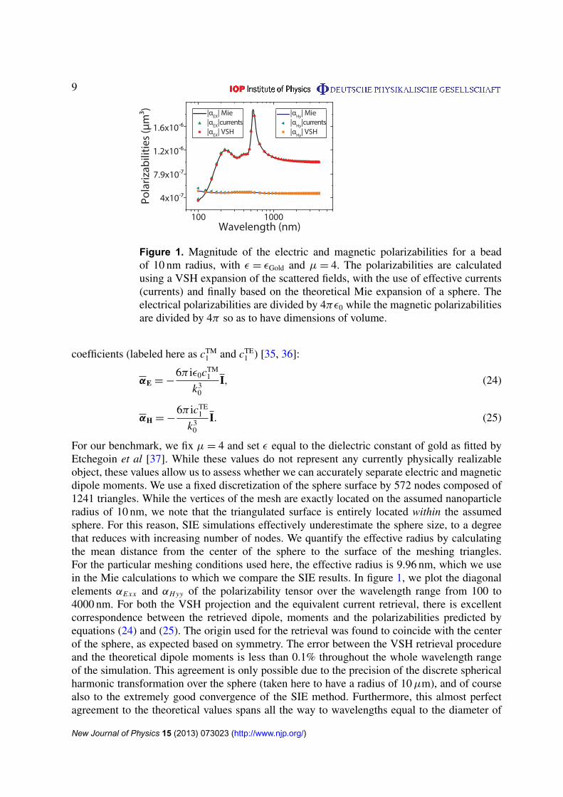
Figure 1. Magnitude of the electric and magnetic polarizabilities for a beadof 10 nm radius, with ε = εGold and µ = 4. The polarizabilities are calculatedusing a VSH expansion of the scattered fields, with the use of effective currents(currents) and finally based on the theoretical Mie expansion of a sphere. Theelectrical polarizabilities are divided by 4πε0 while the magnetic polarizabilitiesare divided by 4π so as to have dimensions of volume.
coefficients (labeled here as cTM1 and cTE
1 ) [35, 36]:
αE = −6π iε0cTM
1
k30
I, (24)
αH = −6π icTE
1
k30
I. (25)
For our benchmark, we fix µ = 4 and set ε equal to the dielectric constant of gold as fitted byEtchegoin et al [37]. While these values do not represent any currently physically realizableobject, these values allow us to assess whether we can accurately separate electric and magneticdipole moments. We use a fixed discretization of the sphere surface by 572 nodes composed of1241 triangles. While the vertices of the mesh are exactly located on the assumed nanoparticleradius of 10 nm, we note that the triangulated surface is entirely located within the assumedsphere. For this reason, SIE simulations effectively underestimate the sphere size, to a degreethat reduces with increasing number of nodes. We quantify the effective radius by calculatingthe mean distance from the center of the sphere to the surface of the meshing triangles.For the particular meshing conditions used here, the effective radius is 9.96 nm, which we usein the Mie calculations to which we compare the SIE results. In figure 1, we plot the diagonalelements αExx and αH yy of the polarizability tensor over the wavelength range from 100 to4000 nm. For both the VSH projection and the equivalent current retrieval, there is excellentcorrespondence between the retrieved dipole, moments and the polarizabilities predicted byequations (24) and (25). The origin used for the retrieval was found to coincide with the centerof the sphere, as expected based on symmetry. The error between the VSH retrieval procedureand the theoretical dipole moments is less than 0.1% throughout the whole wavelength rangeof the simulation. This agreement is only possible due to the precision of the discrete sphericalharmonic transformation over the sphere (taken here to have a radius of 10 µm), and of coursealso to the extremely good convergence of the SIE method. Furthermore, this almost perfectagreement to the theoretical values spans all the way to wavelengths equal to the diameter of
New Journal of Physics 15 (2013) 073023 (http://www.njp.org/)
10
the sphere. This agreement is hence beyond what is needed for metamaterial analysis wherewavelengths around five to ten times bigger than the structures are commonly used. Whenexamining the current retrieval procedure, we find that the error between the effective currentsretrieval and the theoretical electric dipole moments is less than 0.006% at 4000 nm and growsmonotonically up to 1% at 100 nm wavelength. For the magnetic dipole, it is 0.03% at 4000 nmand 8.7% at 100 nm. The difference between the rigorous values and those extracted fromthe effective currents method is due to the fact that the current-to-dipole expressions usedin the current retrieval procedure (equations (16) and (17)) are only valid for krmax�1 asexplained by Jackson [25]. These two equations, which are the equations commonly used in themetamaterial field [38–40], derive from exact formulae (9.167 and 9.168 in [25]) by replacingthe involved spherical Bessel functions with their small-argument asymptotes. Therefore, theeffective current method is only expected to be accurate for r � λ/2π (i.e. kr ∼ 1). The erroris thus not a numerical error but an error due to a poorly met approximation. This error, andwhether it is larger for p than for m or vice versa, depends not only on the size of the scattererbut also on the specific weighting given by the current distribution. In contrast, the VSH retrievalthrough fields is valid for arbitrary frequency and arbitrary size of the radiating object.
The VSH retrieval method can be downloaded from our webpage, to be used withthe fields calculated with any full-wave maxwell solver (www.amolf.nl/research/resonant-nanophotonics).
4. Polarizability retrieval applied to Kerker’s paradox of zero-forward scattering spheres
As a more challenging benchmark, we also consider magnetoelectric spheres where materialparameters are set to the very special condition that is the subject of Kerker’s paradox raisedin [1] and resolved in [2]. It was first noted by Kerker [1] that at a particular combination of ε
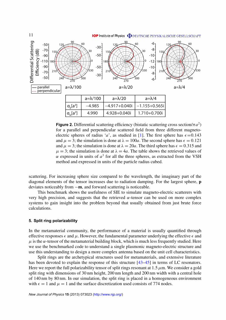
and µ, spheres appear to have zero-forward scattering, yet non-zero extinction. This apparentparadox that occurs for very small spheres when ε = (4 − µ)/(2µ + 1) gained new interest inthe framework of cloaking and invisibility [41, 42]. Alu and Engheta [2] showed that thesespheres indeed have very low yet non-zero forward scattering, thereby complying with theoptical theorem. The almost zero-forward scattering results from destructive interference in theforward direction of the radiation of the generated electric dipole and magnetic dipole moments.Here we reproduce three of the examples studied by Alu [2], using the SIE method (see figure 2),and retrieve the polarizability tensor. First, in figure 2 the bistatic scattering cross section ordifferential scattering efficiency is plotted for the spheres treated in [2]. The spheres havedifferent radii a = λ/100, λ/20 and λ/4. The permeability of the three spheres is µ = 3 whilethe permittivity is ε = 0.143, 0.121 and 0.315. It should be noted that for larger spheres, thecondition of minimal forward scattering is shifted away from the criterion ε = (4 − µ)/(2µ + 1).The calculated efficiencies are in excellent quantitative agreement with the values reported byAlu [2]. It is evident that the forward scattering for the three spheres is close to zero. We reportas a table in figure 2(b) the retrieved values of α expressed in units of a3 for all the three cases,as extracted from the VSH method and expressed in units of the particle radius cubed. All off-diagonal elements are at least 105 times smaller than the diagonal elements, i.e. zero withinnumerical precision. The retrieved polarizabilities are isotropic to within 0.1%. We thereforeonly report the mean diagonals αE and αH . Evidently, for all three spheres the condition p = −mrequired for complete destructive interference in the forward direction is almost met, consistentwith the conclusion derived in [2] and [1] that this is a necessary condition for zero-forward
New Journal of Physics 15 (2013) 073023 (http://www.njp.org/)
11
Figure 2. Differential scattering efficiency (bistatic scattering cross section/πa2)for a parallel and perpendicular scattered field from three different magneto-electric spheres of radius ‘a’, as studied in [1]. The first sphere has ε=0.143and µ = 3; the simulation is done at λ = 100a. The second sphere has ε = 0.121and µ = 3; the simulation is done at λ = 20a. The third sphere has ε = 0.315 andµ = 3; the simulation is done at λ = 4a. The table shows the retrieved values ofα expressed in units of a3 for all the three spheres, as extracted from the VSHmethod and expressed in units of the particle radius cubed.
scattering. For increasing sphere size compared to the wavelength, the imaginary part of thediagonal elements of the tensor increases due to radiation damping. For the largest sphere, pdeviates noticeably from −m, and forward scattering is noticeable.
This benchmark shows the usefulness of SIE to simulate magneto-electric scatterers withvery high precision, and suggests that the retrieved α-tensor can be used on more complexsystems to gain insight into the problem beyond that usually obtained from just brute forcecalculations.
5. Split ring polarizability
In the metamaterial community, the performance of a material is usually quantified througheffective responses ε and µ. However, the fundamental parameter underlying the effective ε andµ is the α-tensor of the metamaterial building block, which is much less frequently studied. Herewe use the benchmarked code to understand a single plasmonic magneto-electric structure anduse this understanding to design a more complex antenna based on the unit cell characteristics.
Split rings are the archetypical structures used for metamaterials, and extensive literaturehas been devoted to explain the response of this structure [43–45] in terms of LC resonators.Here we report the full polarizability tensor of split rings resonant at 1.5 µm. We consider a goldsplit ring with dimensions of 30 nm height, 200 nm length and 200 nm width with a central holeof 140 nm by 80 nm. In our simulation, the split ring is placed in a homogeneous environmentwith ε = 1 and µ = 1 and the surface discretization used consists of 774 nodes.
New Journal of Physics 15 (2013) 073023 (http://www.njp.org/)
12
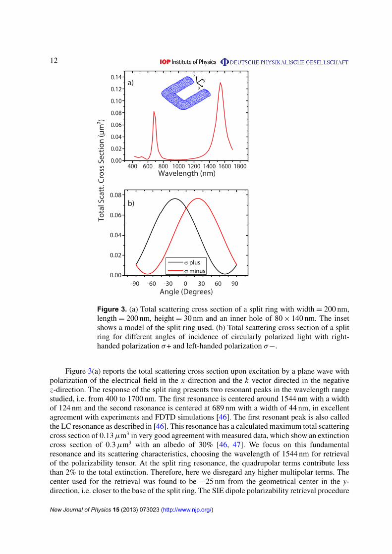
Figure 3. (a) Total scattering cross section of a split ring with width = 200 nm,length = 200 nm, height = 30 nm and an inner hole of 80 × 140 nm. The insetshows a model of the split ring used. (b) Total scattering cross section of a splitring for different angles of incidence of circularly polarized light with right-handed polarization σ+ and left-handed polarization σ−.
Figure 3(a) reports the total scattering cross section upon excitation by a plane wave withpolarization of the electrical field in the x-direction and the k vector directed in the negativez-direction. The response of the split ring presents two resonant peaks in the wavelength rangestudied, i.e. from 400 to 1700 nm. The first resonance is centered around 1544 nm with a widthof 124 nm and the second resonance is centered at 689 nm with a width of 44 nm, in excellentagreement with experiments and FDTD simulations [46]. The first resonant peak is also calledthe LC resonance as described in [46]. This resonance has a calculated maximum total scatteringcross section of 0.13 µm3 in very good agreement with measured data, which show an extinctioncross section of 0.3 µm3 with an albedo of 30% [46, 47]. We focus on this fundamentalresonance and its scattering characteristics, choosing the wavelength of 1544 nm for retrievalof the polarizability tensor. At the split ring resonance, the quadrupolar terms contribute lessthan 2% to the total extinction. Therefore, here we disregard any higher multipolar terms. Thecenter used for the retrieval was found to be −25 nm from the geometrical center in the y-direction, i.e. closer to the base of the split ring. The SIE dipole polarizability retrieval procedure
New Journal of Physics 15 (2013) 073023 (http://www.njp.org/)

13
allows us to quantify both the diagonal values in the polarizability tensor and the crosscouplingbetween the magnetic and electric moments. We find the following values for the VSH andeffective current retrieval procedures, where V denotes the geometrical volume of the split ring(V = 6.33 × 10⁻⁴ µm3).
Elements of α VSH Eff. currentsαEx /(4πV ε0) −1.38 + 10.47i 0.32 + 10.87iαEy/(4πV ε0) 1.52 + 0.10i 1.53 + 0.10iαEz/(4πV ε0) 0.11i 0.12
αE Hxz/(4πV/c) −2.83 − 0.41i −2.92 + 0.04iαH Ezx /(4πV/Z) 2.85 + 0.48i 2.92 − 0.00i
αHx /(4πV ) −0.01i −0.01αHy/(4πV ) 0 0αHz/(4πV ) −0.15 + 0.78i −0.02 + 0.79i
(26)
All the other values in the polarizability tensor are 10−3 below αEx . Both retrieval proceduresindicate that the scatterer has magneto-electric nature given the values of the magnetic and crosspolarizabilities. The difference in magnitude between both retrieval procedures is maximally16%. Based on the MIE calculations, we already saw that the VSH retrieval procedure isaccurate, whereas the common current-based definition is fundamentally limited and only validfor small objects of size r < λ/2π . This condition is not met for the split ring. Therefore, wewill focus now on the values retrieved with the VSH procedure. The electric polarizability forthe px oriented dipole αEx is the largest polarizability in this structure, and is well in excessof the physical particle volume. Thereby the split ring is very much like a strongly plasmonicparticle. That the retrieved αEx is mostly imaginary confirms that λ = 1544 nm correspondsto resonant driving. The magnetic polarizability for the mz oriented dipole αHz is 13 timessmaller than the electric polarizability. The off-diagonal values αE Hxz and αH Ezx significantlyexceed the magnetic polarizability. We note that the retrieval very well confirms fundamentalconstraints on the cross polarizabilities. In particular, the cross polarizabilities are the negativeof each other to within 2%, as fundamentally expected from Onsager relations. Also the phaserelations arg(αE Hxz/αEx ) = π/2 and arg(αHz/αEx ) = 0 are satisfied to within 0.06 rad. Thesephase relations are consistent with the LC-circuit intuition that if a magnetic response arisesthrough electric driving, i.e. through cross polarizability, it must lag by a quarter wave, as it isdue to relaxation of the charge that accumulates in response to E across the capacitor. Finally,we note that αH Ezx = i
√αHzαEx to within 0.4%. These data comply excellently with [45],
which claims that for planar scatterers that can be described by a circuit model the α tensormust have ‘maximally strong’ cross coupling. The numerical values that we retrieve are inreasonable accordance with experimentally retrieved values [45], which were reported to beapproximately |αEx | = 6.4 V, |αHz | = 0.9 V and |αH Ezx | = 2.1 V. That the split ring in ourmodel is comparatively even less magnetic than extracted in experiments is likely due to eitherone of two causes. Firstly, the split ring resonator (SRR) response depends sensitively ongeometrical details such as the exact gap size and the rounding assumed for approximating theSRR shape. The SRR that we model is comparatively thin and rounded compared to the SRRs inexperiments. Secondly, in the experiments the polarizability was retrieved rather indirectly, froma comparison of SRR array transmission to a lattice summation model. The fact that SRRs werelocated at an air–glass interface was disregarded. At a dielectric interface, polarizabilities can
New Journal of Physics 15 (2013) 073023 (http://www.njp.org/)

14
be significantly renormalized [48]. A strong response in the αE H cross-coupled polarizabilityelements implies that the structure possesses optical activity as explained in [45]. Indeedfigure 3(b) shows strong optical activity for the split ring, as evidenced by the change oftotal scattering cross section for right- and left-handed circularly polarized light excitations atdifferent incident angles. Thereby SIE confirms the optical activity expected for any magneto-electric scatterer with a magneto-electric cross coupling term in its α-tensor [45]. The angleof maximum optical activity θMAX is consistent with the right eigen-vectors found from thediagonalization of alpha. Indeed, we find that the maximum response of this structure occursfor an eigen-excitation with E = (0.964, 0, 0)E0 and H = (0, 0, 0.0093 − 0.264i)E0/Z , and theminimum response occurs when E = (0.00396 − 0.261i, 0, 0)E0 and H = (0, 0, 0.965)E0/Z(where Z is the characteristic impedance of free space). These excitations require a phasedelay between Ex and Hz that can be generated by using an easily experimentally achievablecircularly polarized plane wave under oblique incidence. Furthermore, it is straightforward tocalculate that the maximum coupling of a circularly polarized plane wave with a split ring ofpolarizability as in equation (26) should occur at a polar angle ∼20◦ whose full-wave SIE indeedshows as the angle of maximum scattering.
6. Single split ring as a magnetic dipole converter
One of the most exciting features of plasmonic antennas is that since the plasmons are acombined oscillation of the optical fields and the free electrons in the metal, their resonancescan be confined to very small modal volumes [3]. These small modal volumes make plasmonicantennas perfect candidates for coupling to single emitters since local fields and LDOS areenhanced [49]. Some of the functionalities that have been already experimentally proven forsingle emitters coupled to these antennas are change of polarization of the emitted field by usingrod antennas [50] and directionality in the emission of the emitter through the use of Yagi–Udaantennas [51]. We present calculations of the interaction between a single emitter and anSRR.
A technical issue is that the field of a dipolar source driving the scatterer is singular atthe position of the emitter. Therefore, unless a very fine discretization is used simulationsare prone to large numerical errors. This holds for virtually any brute force method. In thecase of SIE, this problem occurs when calculating the values of q (see equation(10)) forfields coming from a dipole in close proximity to the scatterer. However, since the fieldof the dipole source is given by the Green function of the environment, we can follow asimilar procedure to equations (11 and 12), in which the integral over G(r, r0) is separatedinto a smooth G(r, r0)S and a singular part G(r, r0)NS, leading to the following equationfor q:
q =
{∫Sm
dS(ω2µµ0)(G(r0, r)S + G(r0, r)NS) · fm(r) · p, m = 1, ..., N ,∫Sm−N
dS(iω)(∇(G(r0, r)S + G(r0, r)NS)) × fm−N (r)) · p, m = N + 1, ..., 2N ,(27)
where we used equation (10) and the fact that G(r, r′)T= G(r′, r) and (∇ × G(r, r′))T
= −∇ ×
G(r′, r) for the free space Green function [30], and the identity ∇ × G(r0, r) = ∇G(r0, r) × 1([26, equation 28]). With µµ0 we denote the permittivity of the environment where the emittingdipole is positioned. The smooth part can be calculated by a normal quadrature routine.
New Journal of Physics 15 (2013) 073023 (http://www.njp.org/)
15
The singular part can be calculated by using the integration of the RWG function found in [52],i.e. by
qNS =
∫Sm
dS(ω2µµ0)((3Ln
8πk2i[ 1
A+n(
k2i2 K1
3(T +n ) − K−1
3 (T +n ))...
−1
A−n(
k2i2 K1
3(T −
n ) − K−13 (T −
n ))])...
+( 14π
[K−12 (Sn) −
k2i2 K1
2(Sn)])) · p, m = 1, ..., N∫Sm−N
dS(iω)( 14π
[K−14 (Sm−N ) −
k2i2 K1
4(Sm−N )]) · p, m = N + 1, ..., 2N ,
(28)
where Klj(Tn) are the integrals defined in [52] that are performed over the triangle Tn or over the
surface Sn linked to the triangle with the same index. After having found q, we find the strengthof the current densities J and M by finding αn and βn, as already explained. It is important to notethat this same procedure can be used to find the scattered field at the source and thereby the localdensity of states (LDOS) [53] when using SIE, avoiding the common problems encounteredwhen working with fields from a dipolar emitter close to scattering structures.
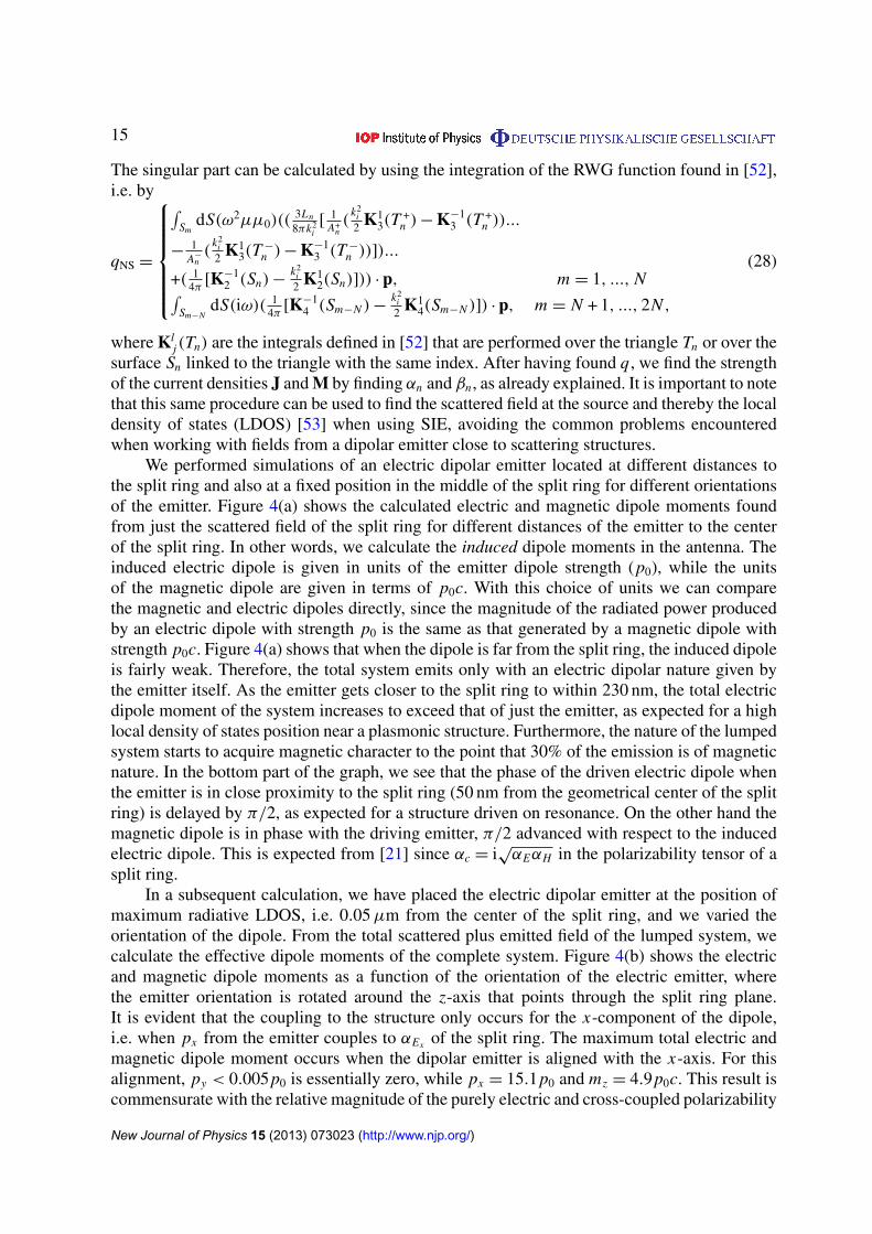
We performed simulations of an electric dipolar emitter located at different distances tothe split ring and also at a fixed position in the middle of the split ring for different orientationsof the emitter. Figure 4(a) shows the calculated electric and magnetic dipole moments foundfrom just the scattered field of the split ring for different distances of the emitter to the centerof the split ring. In other words, we calculate the induced dipole moments in the antenna. Theinduced electric dipole is given in units of the emitter dipole strength (p0), while the unitsof the magnetic dipole are given in terms of p0c. With this choice of units we can comparethe magnetic and electric dipoles directly, since the magnitude of the radiated power producedby an electric dipole with strength p0 is the same as that generated by a magnetic dipole withstrength p0c. Figure 4(a) shows that when the dipole is far from the split ring, the induced dipoleis fairly weak. Therefore, the total system emits only with an electric dipolar nature given bythe emitter itself. As the emitter gets closer to the split ring to within 230 nm, the total electricdipole moment of the system increases to exceed that of just the emitter, as expected for a highlocal density of states position near a plasmonic structure. Furthermore, the nature of the lumpedsystem starts to acquire magnetic character to the point that 30% of the emission is of magneticnature. In the bottom part of the graph, we see that the phase of the driven electric dipole whenthe emitter is in close proximity to the split ring (50 nm from the geometrical center of the splitring) is delayed by π/2, as expected for a structure driven on resonance. On the other hand themagnetic dipole is in phase with the driving emitter, π/2 advanced with respect to the inducedelectric dipole. This is expected from [21] since αc = i
√αEαH in the polarizability tensor of a
split ring.In a subsequent calculation, we have placed the electric dipolar emitter at the position of
maximum radiative LDOS, i.e. 0.05 µm from the center of the split ring, and we varied theorientation of the dipole. From the total scattered plus emitted field of the lumped system, wecalculate the effective dipole moments of the complete system. Figure 4(b) shows the electricand magnetic dipole moments as a function of the orientation of the electric emitter, wherethe emitter orientation is rotated around the z-axis that points through the split ring plane.It is evident that the coupling to the structure only occurs for the x-component of the dipole,i.e. when px from the emitter couples to αEx of the split ring. The maximum total electric andmagnetic dipole moment occurs when the dipolar emitter is aligned with the x-axis. For thisalignment, py < 0.005p0 is essentially zero, while px = 15.1p0 and mz = 4.9p0c. This result iscommensurate with the relative magnitude of the purely electric and cross-coupled polarizability
New Journal of Physics 15 (2013) 073023 (http://www.njp.org/)

16
Figure 4. Single emitter in the vicinity of a split ring. In (a) we show thecalculated dipolar moment of the scattered field for different distances to the splitring center. In (b) we show the dipolar moment of the total field (scattered fieldplus single emitter field) for different orientation angles of the single emitter in aposition 0.05 µm from the center of the split ring. The angles are rotated aroundthe z-axis and therefore the x and y electric dipoles are shown as well as the zmagnetic dipole. The other components of the electric as well as the magneticdipoles are negligible in magnitude. In (c) we show the scattered field patternof a split ring excited by an electric dipolar emitter at the position on maximumcoupling. The electric field magnitude |E |
2 is calculated at a radius of 100 µmfrom the center of the split ring. The red continuous line shows the field in theplane ‘xy’ and the blue dashed line shows the field in the plane ‘yz’. In (d) weshow the calculation of the normalized total and radiative LDOS for differentpositions in a line along the y-axis through the center of the split ring.
of the split ring in equation (26), indicating that the dipolar scattering approximation of thesplit ring can be used for dipolar emitter excitations while still obtaining an agreement of85% with the full-wave calculation. It is important to note that this agreement is dependenton the distance of the emitter to the split ring, since dipolar emitters in close proximity to aplasmonic structure (typically < 20 nm) can increasingly excite higher multipolar moments ofthe plasmonic structures due to the strong gradients in the exciting fields [54]. When the dipolar
New Journal of Physics 15 (2013) 073023 (http://www.njp.org/)

17
emitter is aligned with the y-axis, i.e. rotation angle π /2, then py = 0.44p0, px = 0.12p0 andmz = 0.04p0c. This result indicates, first, that py hardly induces a magnetic dipole and, second,that this position has a local density of states for y-oriented dipoles lower than free space.Figure 4(c) shows a polar plot of the far-field intensity distribution of the scattered field for asplit ring, excited with a dipole located at the position of maximum coupling and aligned alongthe gap of the split ring, i.e. along the x-direction. The |E |
2 distribution is evidently differentfrom that of an electric dipole, since on the one hand the emission is asymmetric in the y-axisdue to the front-to-back asymmetry of the split ring, and on the other hand the emission in thex-axis is different from zero, evidencing the partial magnetic nature of the scatterer. Finallyin figure 4(d), we show the calculated total and radiative LDOS normalized to the vacuumLDOS. The calculations are done for different positions on the y-axis along a line that startsat the center of the split ring. The maximum total and radiative LDOS occurs at a position∼50 nm away from the center of the split ring. While at this position the total LDOS for anx-oriented dipole is ∼75ρ0, the radiative LDOS for an x oriented dipole is ∼252.7ρ0. Thisradiative LDOS is consistent with the generated total electric dipolar moment of 15.1p0 andthe magnetic moment of 4.9p0c for the lumped system. These values for the dipole momentsindicate a radiative LDOS enhancement of (p2 + m2)/p2
0 = 252. The fact that the total LDOS isthree times the radiative LDOS is consistent with experimental measurements of the albedo of∼30% measured for a single Au split ring by Husnik et al [47]. The relative magnitude of thetotal versus radiative LDOS indicates that the quantum efficiency of the system is η ∼ 33%.
7. Split ring array antenna
Having understood the split ring as a system composed of an electric and a magnetic coupleddipole moment whose maximal response to circularly polarized plane waves occurs for a certainpolar angle θMAX, and having studied the way in which electric dipoles couple to single splitrings, we turn to the design of an array of split rings and to the study of the special propertiesthat arise from it. In our design, we combine two of our earlier results. Firstly, figure 3 shows thatthe purest handed response is obtained at an off-normal incidence of 20◦. Secondly, excitationof a split ring array with a single molecule is most advantageous when placed 50 nm fromthe geometrical center and with a dipolar orientation along the gap. In addition, we knowfrom [22, 23, 51, 55] that one can attain directionality in the scattering of arrays of particlesby placing them in a linear array with a pitch of ∼λ/3. Our design combines these three ideas inan array of five split rings tilted at θMAX and excited by a dipolar emitter in the central element.Figure 5(a) presents the scattering pattern of the antenna which clearly shows directivity in itsscattering, with scattered fields confined in a half angle < 40◦. By studying the complex fieldsobtained from the front and back scattering from the antenna, we can retrieve the polarizationand plot it on the Poincare sphere, see figure 5(b). We find right-handed elliptically polarizedlight emanating from the front of the antenna (depicted by the blue point in figures 5(a) and (b))and left-handed elliptically polarized light emanating from the back of the antenna. Both fieldshave an electric field seven times stronger in the x-direction than in the y-direction and themajor axis of the ellipse is aligned with the x-axis. Thereby, metamaterial antennas allow newforms of control over emission compared to plasmon antennas. We foresee that with split ringswith a stronger magnetic polarizability term, it would be possible to reach a totally circularpolarized light regime. Reaching stronger magnetic polarizability currently seems easiest atmid-infrared and microwave frequencies [45]. We foresee interesting applications especially
New Journal of Physics 15 (2013) 073023 (http://www.njp.org/)

18
Figure 5. (a) Scattered field pattern of a split ring array antenna showingdirectionality in its scattering. The antenna is excited with a unit dipolepositioned at 50 nm from the center in between the arms of the central split ringin the array. The field is calculated at a sphere 100 µm from the center of theantenna. The solid line shows |E |
2 in the plane zx and the dashed line shows|E |
2 in the plane zy. (b) Depiction of the polarization state of the scattered fieldof the array antenna found on the forward (blue) and backward direction (red).(c) Cartoon model that shows the positioning of the electric dipole on the splitring array antenna as well as the angled relative positioning of the split rings.
if one can reach this at optical frequencies. In this regime one could envision using split ringantennas to generate a single-photon source from a simple linear electric dipole emitter, or froma localized χ (2) nonlinear material that emits its photons in handed beams, or split into twonarrow beams, where handedness and direction are entangled.
8. Conclusions
We have made use of the SIE method to retrieve the polarizability tensor of scatterers. Thisretrieval is performed in two different ways. The first method consists of a VSH projection ofthe scattered fields, which yields extremely good precision for any wavelength and size of thescatterer, thanks to the aid of a discrete harmonic transform on the sphere. With the secondmethod, based on effective electric and magnetic surface currents, we can successfully retrievethe polarizabilities of small scatterers with the advantage that this retrieval can be done onnon-isolated structures. We have used the lumped system of a dipolar emitter and a split ringto show how the radiation nature of the system changes drastically from a simple electricaldipole emitter. In the lumped system the emission is modified by the scattering of the split ring,
New Journal of Physics 15 (2013) 073023 (http://www.njp.org/)

19
which can imprint its magneto-electric nature on the emission. This realization further extendscurrent research efforts that have shown how emission from a single electric dipole transitionin a quantum dot can appear as if it originates from a multipole transition by strong coupling ofthe emitter to a plasmon antenna multipole resonance [56]. Also, such magnetic and magneto-electric antennas may enhance the magnetic LDOS that magnetic transitions are sensitive to, asrecently shown for rare earth ions near an interface [24]. Finally, we used our understanding ofsplit rings to design an array antenna that splits emission from a point source into two beamsof oppositely handed elliptical polarization. For ultimately strong magnetic scatterers, thesefindings might provide new ways of manipulating spins via light, and enhance enantioselectivespectroscopies in the near field [57, 58].
Acknowledgments
We thank M Frimmer and L Langguth for fruitful discussions. This work was part of the researchprogram of the ‘Foundation for Fundamental Research on Matter (FOM)’, which was financiallysupported by the ‘The Netherlands Organization for Scientific Research (NWO)’. This work wassupported by NanoNextNL, a micro and nanotechnology consortium of the Government of theNetherlands and 130 partners. AFK gratefully acknowledges an NWO-Vidi grant for financialsupport.
References
[1] Kerker M, Wang D S and Giles C L 1983 J. Opt. Soc. Am. 73 765–7[2] Alu A and Engheta N 2010 J. Nanophoton. 4 041590[3] Barnes W L, Dereux A and Ebbesen T W 2003 Nature 424 824–30[4] Sonnichsen C, Reinhard B M, Liphardt J and Alivisatos A P 2005 Nature Biotechnol. 23 741–5[5] Lal S, Link S and Halas N J 2007 Nature Photon. 1 641–8[6] Lassiter J B, Aizpurua J, Hernandez L I, Brandl D W, Romero I, Lal S, Hafner J H, Nordlander P and
Halas N J 2008 Nano Lett. 8 1212–8[7] Rahmani M, Lei D Y, Giannini V, Lukiyanchuk B, Ranjbar M, Liew T Y F, Hong M and Maier S A 2012
Nano Lett. 12 2101–6[8] Nehl C L, Liao H and Hafner J H 2006 Nano Lett. 6 683–8[9] Hentschel M, Saliba M, Vogelgesang R, Giessen H, Alivisatos A P and Liu N 2010 Nano Lett. 10 2721–6
[10] Dolling G, Enkrich C, Wegener M, Zhou J F, Soukoulis C M and Linden S 2005 Opt. Lett. 30 3198–200[11] Zhang S, Park Y S, Li J, Lu X, Zhang W and Zhang X 2009 Phys. Rev. Lett. 102 023901[12] Liu N, Guo H, Fu L, Kaiser S, Schweizer H and Giessen H 2008 Nature Mater. 7 31–7[13] Yu N, Aieta F, Genevet P, Kats M A, Gaburro Z and Capasso F 2012 Nano Lett. 12 6328–33[14] Aieta F, Genevet P, Yu N, Kats M A, Gaburro Z and Capasso F 2012 Nano Lett. 12 1702–6[15] Pors A, Nielsen M G, Eriksen R L and Bozhevolnyi S I 2013 Nano Lett. 13 829–34[16] Muhlig S, Menzel C, Rockstuhl C and Lederer F 2011 Metamaterials 5 64–73[17] Yee K 1966 IEEE Trans. Antennas Prop. 14 302–7[18] Goedecke G H and O’Brien S G 1988 Appl. Opt. 27 2431–8[19] Garcıa de, Abajo F J and Howie A 2002 Phys. Rev. B 65 115418[20] Li J and Pendry J B 2007 arXiv:cond-mat/0701332v1[21] Sersic I, Tuambilangana C, Kampfrath T and Koenderink A F 2011 Phys. Rev. B 83 245102[22] Kosako T, Kadoya Y and Hofmann H F 2010 Nature Photon. 4 312–5[23] Koenderink A F 2009 Nano Lett. 9 4228–33
New Journal of Physics 15 (2013) 073023 (http://www.njp.org/)

20
[24] Karaveli S and Zia R 2011 Phys. Rev. Lett. 106 193004[25] Jackson J D 1999 Classical Electrodynamics 3rd edn (New York: Wiley)[26] Kern A M and Martin O J F 2009 J. Opt. Soc. Am. A 26 732–40[27] Harrington R F 1968 Field Computation by Method of Moments (London: MacMillan)[28] Rao S, Wilton D and Glisson A 1982 IEEE Trans. Antennas Prop. 30 409–18[29] Geuzaine C and Remacle J F 2009 Int. J. Numer. Meth. Eng. 79 1309–31[30] Tai C T 1993 Dyadic Green’s Functions in Electromagnetic Theory 2nd edn (New York: IEEE)[31] Mohlenkamp M J 1999 J. Fourier Anal. Appl. 5 159–84[32] Petschulat J, Yang J, Menzel C, Rockstuhl C, Chipouline A, Lalanne P, Tuennermann A, Lederer F and
Pertsch T 2010 Opt. Express 18 14454–66[33] Mohammadi A, Nadgaran H and Agio M 2005 Opt. Express 13 10367–81[34] Lindell I, Sihvola A H, Tretyakov S A and Viitanen A J 1994 Electromagnetic Waves in Chiral and Bi
Isotropic Media (Norwood, MA: Artech House)[35] Li J, Salandrino A and Engheta N 2007 Phys. Rev. B 76 245403[36] Alu A and Engheta N 2005 Phys. Rev. E 72 016623[37] Etchegoin P G, Ru E C L and Meyer M 2006 J. Chem. Phys. 125 164705[38] Papasimakis N, Fedotov V A, Marinov K and Zheludev N I 2009 Phys. Rev. Lett. 103 093901[39] Kaelberer T, Fedotov V A, Papasimakis N, Tsai D P and Zheludev N I 2010 Science 330 1510–2[40] Huang Y W, Chen W T, Wu P C, Fedotov V, Savinov V, Ho Y Z, Chau Y F, Zheludev N I and Tsai D P 2012
Opt. Express 20 1760–8[41] Mehta R V, Patel R, Desai R, Upadhyay R V and Parekh K 2006 Phys. Rev. Lett. 96 127402[42] Garcıa-Camara B, Moreno F, Gonzalez F and Saiz J M 2007 Phys. Rev. Lett. 98 179701[43] Pendry J, Holden A, Robbins D and Stewart W 1999 IEEE Trans. Microw. Theory Tech. 47 2075–2084[44] Enkrich C, Wegener M, Linden S, Burger S, Zschiedrich L, Schmidt F, Zhou J F, Koschny T and
Soukoulis C M 2005 Phys. Rev. Lett. 95 203901[45] Sersic I, van de Haar M A, Bernal Arango F and Koenderink A F 2012 Phys. Rev. Lett. 108 223903[46] Sersic I, Frimmer M, Verhagen E and Koenderink A F 2009 Phys. Rev. Lett. 103 213902[47] Husnik M, Klein M W, Feth N, Konig M, Niegemann J, Busch K, Linden S and Wegener M 2008 Nature
Photon. 2 614–7[48] Kwadrin A and Koenderink A F 2013 Phys. Rev. B 86 125123[49] Akimov A V, Mukherjee A, Yu C L, Chang D E, Zibrov A S, Hemmer P R, Park H and Lukin M D 2007
Nature 450 402–6[50] Taminiau T H, Stefani F D, Segerink F B and van Hulst N F 2008 Nature Photon. 2 234–7[51] Curto A G, Volpe G, Taminiau T H, Kreuzer M P, Quidant R and van Hulst N F 2010 Science 329 930–3[52] Hanninen I, Taskinen M and Sarvas J 2006 Prog. Electromagn. Res. 63 243–78[53] Novotny L and Hecht B 2006 Principles of Nano-Optics (Cambridge: Cambridge University Press)[54] Mertens H, Koenderink A F and Polman A 2007 Phys. Rev. B 76 115123[55] Bernal Arango F, Kwadrin A and Koenderink A F 2012 ACS Nano 6 10156–67[56] Curto A G, Taminiau T H, Volpe G, Kreuzer M P, Quidant R and van Hulst N F 2013 Nature Commun.
4 1750–7[57] Schaferling M, Dregely D, Hentschel M and Giessen H 2012 Phys. Rev. X 2 031010[58] Tang Y and Cohen A E 2010 Phys. Rev. Let 104 163901
New Journal of Physics 15 (2013) 073023 (http://www.njp.org/)