polarization of light waves - bayanbox.irbayanbox.ir/view/6350103148579154916/chapter7.pdf ·...
TRANSCRIPT

C H A P T E R 3
Polarization of Light Waves
3.1 STATES OF POLARIZATION
Consider a monochromatic plane wave
⇀
E �⇀r � t� = ⇀
E0 ei�kz−�t�� (3.1a)⇀
B �⇀r � t� = ⇀
B0 ei�kz−�t�� (3.1b)
propagating in the positive z-direction in an isotropic medium. The amplitude
vectors⇀
E0 and⇀
B0 are in general complex. The direction of the electric field
amplitude⇀
E0, quite arbitrarily but in accordance with the common usage, istaken to represent the state of polarization of light. For light propagating in freespace and in other non-absorbing isotropic media, the polarization state is com-pletely described by the transverse components of its electric field. Accordingly,Eq. (3.1a) can be expressed as
⇀
E �x� y� z� t� =Exi+Eyj (3.2a)
= �E0xi+E0yj� ei�kz−�t�� (3.2b)
For definiteness, the x and y axes in the transverse plane are taken along thehorizontal and vertical directions, respectively. It may not be out of place tomention at this point that the phase of a monochromatic plane wave is arbitrarilychosen to be �kz−�t� and not ��t −kz�. This minor detail needs to be statedbecause the terms like ‘phase advance’ and ‘phase lag’ to be used later aredependent on this choice.
3.1.1 Linear Polarization
Light is linearly polarized if the field components Ex and Ey oscillate in phase or180� out of phase. This is ensured if E0x and E0y are real. The field components
121

122 Chapter 3: POLARIZATION OF LIGHT WAVES
Ey
Ex
θ
y
x
E
Fig. 3.1: Linearly polarized light.
attain extremum values at the same time. A wave is horizontally polarized �EH�if Ey is identically zero and vertically polarized �EV� when Ex vanishes. Thegeneral state of linear polarization �E�� occurs when Ex and Ey are both non-zero. The direction of polarization of the wave then makes an angle � with thex-direction, where � = tan−1
(E0y/E0x
). This is shown in Fig. 3.1.
As time changes, the tip of the electric vector at a given point oscillates alonga fixed line (hence the name, linear polarization) in the transverse plane with aperiod T = 2/�. At other points along the direction of propagation, the electricvectors oscillate in exactly the same manner along parallel lines which lie ina plane containing the direction of propagation (Fig. 3.2a). Alternatively, one
E E E E
z
(a)
E
z
(b)
Fig. 3.2: Linearly polarized light; (a) tips of electric field vectors oscillate alongparallel lines in a fixed plane, (b) instantaneous distribution of electric field vectors.

3.1: STATES OF POLARIZATION 123
can imagine taking a snap shot of the electric vectors. The snap shot will revealelectric vectors distributed sinusoidally along the direction of propagation in aplane which contains the direction of propagation (Fig. 3.2b). For that reason, alinearly polarized wave is also called a plane-polarized wave. It should, however,be understood that the above visualization is only through thought experimentssince no detector exists to follow the rapidly changing light fields.
3.1.2 Elliptical and Circular Polarizations
For complex E0x and E0y, the oscillations of the field components along thehorizontal and vertical directions are generally not in phase, and we can write
Ex = x ei�kz−�t+�x�� (3.3a)
Ey = y ei�kz−�t+�y�� (3.3b)
where the amplitudes x and y are now real. For plane-polarized light,
�y −�x = 0�± (3.4)
so that
Ey
Ex
= y
x
for �y = �x� (3.5a)
Ey
Ex
= −y
x
for �y = �x ±� (3.5b)
The proportionality of the field components �Ey = ±�y/x�Ex is an essentialrequirement for the wave to be linearly polarized. When the field componentsalong the horizontal and vertical directions do not oscillate in phase or exactlyout of phase, the tip of the electric vector in general traces an ellipse in thetransverse plane, called the polarization ellipse. The ellipticity and orientationof this ellipse depend on the amplitude ratio y/x and the phase difference��y −�x�. Eliminating �kz−�t� from the real fields
Ex = x cos�kz−�t +�x�� (3.6a)
Ey = y cos�kz−�t +�y�� (3.6b)
we obtain(
Ey
y
)2
+(
Ex
x
)2
−2(
Ey
y
)(Ex
x
)cos �0 = sin2 �0� (3.7)

124 Chapter 3: POLARIZATION OF LIGHT WAVES
where �0 = �y −�x. This is the general equation of an ellipse with its principalaxes rotated with respect to the horizontal and vertical directions. For �0 =±�m+ 1
2 �, where m is an integer, Eq. (3.7) reduces to
(Ey
y
)2
+(
Ex
x
)2
= 1� (3.8)
The polarization ellipse, in this case, is symmetrically oriented with respect to thecoordinates axes (Fig. 3.3a). For x = y and �0 = ±�m+ 1
2 �, the polarizationellipse degenerates into a circle (Fig. 3.3b). Linear polarization is obtained for�0 = 0, ± (Fig. 3.3c,d). For phase differences other than the multiples of /2and , light is elliptically polarized with the polarization ellipse asymmetricallyoriented with respect to the horizontal and vertical directions. The major axisof the ellipse makes an angle � with the horizontal direction (Fig. 3.3e). Thepolarization ellipse is contained in a rectangle of sides 2x and 2y parallel to
Ex
yE
E
xε Ex
Ey
Eyε
Ex
εy
εx
Ey
E
Ex
Ey
Eεy’
C’
εx2
B’
yε2
yE’Ey
xE’
Ex
A’
(a) (b) (c)
BA
D
ψχ εx’
D’
C
(e)(d)
Fig. 3.3: States of polarization of a plane wave; (a) elliptical polarization withmajor and minor axes along horizontal and vertical directions, (b) circular polar-ization, (c) linear polarization along a line with positive slope, (d) linear polariza-tion along a line with negative slope, (e) general state of elliptical polarization.

3.1: STATES OF POLARIZATION 125
the horizontal and vertical axes, respectively. This ellipse is also contained inanother rectangle of sides 2′
x and 2′y, where 2′
x and 2′y are the lengths of
the major and minor axes of the polarization ellipse, respectively. The angles �and � in Fig. 3.3e give the ellipticity and orientation of the polarization ellipse,respectively.
3.1.3 Helicity of Light Waves
The electric vector of the elliptically polarized light rotates with its tip tracingan ellipse in the transverse plane. The same ellipse can be traced by clockwiseor counter-clockwise rotation of the electric vector. This gives rise to two statesof helicity for the elliptically polarized light. We need to define unambiguouslythe terms ‘clockwise’ and ‘counter-clockwise’ rotations in the present context.To fix this nomenclature, we take �0 = �y −�x = ±/2, although the argumentholds for any �0. Equations (3.6) now become
Ex = x cos�kz0 −�t��
Ey = ∓y sin�kz0 −�t��
where the �−� and �+� signs correspond to �0 = +/2 and �0 = −/2, respec-tively, and z0 is any given point on the z-axis. Table 3.1 lists values of Ex andEy at some specified times within a period of oscillation. The initial time t0 ischosen to make the initial phase kz0 −�t0 = 0.
Figure 3.4 shows the corresponding polarization ellipses. It is seen that for�0 = +/2, the ellipse is traced in the counter-clockwise direction as seen fromabove against the direction �+z� of propagation of light. This represents left ellip-tically polarized light or light with negative helicity (Fig. 3.4a). For �0 = −/2,
Table 3.1. Values of Ex and Ey for �0 =/2 and −/2.
t�0 = +/2 �0 = −/2Ex Ey Ex Ey
t0 +x 0 +x 0
t0 +
2�0 +y 0 −y
t0 +
�−x 0 −x 0
t0 + 3
2�0 −y 0 +y

126 Chapter 3: POLARIZATION OF LIGHT WAVES
Ex
E y
xεyε
yεxε
E y
xE
E
(a)
E
(b)
Fig. 3.4: Polarization ellipse; (a) left elliptical polarization (�0 = +/2), (b) rightelliptical polarization ��0 = −/2�.
the electric vector appears to rotate clockwise as seen against the direction ofpropagation. This corresponds to right elliptically polarized light or light withpositive helicity (Fig. 3.4b). The helicity of the circularly polarized light isdefined in a similar manner. There is no special reason to call light with elec-tric vector rotating in the clockwise (counter-clockwise) direction as right (left)elliptically polarized light. This nomenclature is, however, generally preferred.
For �0 = +/2, the field component Ex leads Ey since Ex reaches its max-imum value one quarter of a period before Ey reaches its maximum value(Fig. 3.5a). A similar argument shows that Ex lags behind Ey for �0 = −/2(Fig. 3.5b).
It must be stated once again that the terms leading and lagging of the fieldsin the present context is linked to our choice �kz−�t� to represent the phaseof a plane wave. Some authors use ��t −kz� for the phase of a plane wave, inwhich case the terminologies will be just the opposite.
π2
π2
+φ0
(a) (b)= 0 = − φ
0 T T0
Ex Ey Ey Ex
T4
T4 t t
Fig. 3.5: Horizontal component of electric field Ex (a) leads the vertical com-ponent Ey for �0 = +/2 and (b) lags behind the vertical component Ey for�0 = −/2.

3.2: THE POLARIZATION ELLIPSE 127
3.2 THE POLARIZATION ELLIPSE
The most general form of the polarization ellipse is shown in Fig. 3.3e. Theangle of inclination of this ellipse will be shown to be given by
tan 2� = 2xy cos �0
2x −2
y
� (3.9)
For arbitrary �0, the ellipse is not symmetrical about the horizontal and ver-tical axes, but is obviously symmetrical about its principal axes ′
x and ′y.
Equation (3.7) when referred to the principal axes of the ellipse is transformed to
(E′
x
′x
)2
+(
E′y
′y
)2
= 1�
where
E′x = ′
x cos�kz−�t +�′x��
E′y = ′
y cos�kz−�t +�′y��
Here, ′x and ′
y are, respectively, the semi-major and semi-minor axes of thepolarization ellipse and �′
y −�′x = ±/2. Therefore, we can write
E′x = ′
x cos�kz−�t +�′0�� E′
y = ∓′y sin�kz−�t +�′
0�� (3.10)
The �∓� signs correspond to �′y −�′
x = ±/2. The components of the electricfield in the two coordinate systems are related:
E′x = Ex cos � +Ey sin �� (3.11a)
E′y = −Ex sin � +Ey cos �� (3.11b)
Substituting Eqs (3.6) with �x = 0, �y = �0 and Eqs (3.10) into Eqs (3.11), weobtain
′x cos �′
0 cos�kz−�t�−′x sin �′
0 sin�kz−�t�
=�x cos � +y sin � cos �0 cos�kz−�t�
−y sin � sin �0 sin�kz−�t��

128 Chapter 3: POLARIZATION OF LIGHT WAVES
∓′y sin �′
0 cos�kz−�t�∓′y cos �′
0 sin�kz−�t�
=�−x sin � +y cos � cos �0 cos�kz−�t�
−y cos � sin �0 sin�kz−�t��
For these equalities to hold for all t and z, following conditions must be satisfied:
′x cos �′
0 = x cos � +y sin � cos �0� (3.12a)
′x sin �′
0 = y sin � sin �0� (3.12b)
∓′y sin �′
0 = −x sin � +y cos � cos �0� (3.12c)
∓′y cos �′
0 = −y cos � sin �0� (3.12d)
Multiplying Eq. (3.12a) with Eq. (3.12c) and Eq. (3.12b) with Eq. (3.12d), weget
∓′x
′y sin �′
0 cos �′0 = (
x cos � +y sin � cos �0
)× (−x sin � +y cos � cos �0
)
= xy cos �0 cos 2� + (2y cos2 �0 −2
x
)sin � cos � (3.13a)
∓′x
′y sin �′
0 cos �′0 = −2
y sin2 �0 sin � cos �� (3.13b)
The desired result (Eq. 3.9) can be obtained by subtracting Eq. (3.13b) fromEq. (3.13a), giving
tan 2� = 2xy cos �0
2x −2
y
�
Squaring and adding Eqs (3.12a) and (3.12d) gives
′2x +′2
y = 2x +2
y� (3.14a)
Further, by adding the product of Eq. (3.12a) with Eq. (3.12d) to the product ofEq. (3.12b) with Eq. (3.12c), we obtain
∓′x
′y = xy sin �0� (3.14b)
Combining Eqs (3.14a) and (3.14b), one gets
∓ ′x
′y
′2x +′2
y
= xy sin �0
2x +2
y
� (3.15a)

3.3: MATRIX REPRESENTATION OF POLARIZATION STATES 129
which is equivalent to
sin�2�� = sin�2�� sin �0� (3.15b)
where
tan � = y
x
� tan � = ∓′y
′x
� (3.16)
The negative sign in Eqs (3.14b) and (3.15a) corresponds to clockwise �−2 ≤
�0 ≤ 0� and positive sign to counter-clockwise �0 ≤ �0 ≤ 2 � rotations of the
electric vector. The ellipticity angle � carries information on the ellipticity andsense of rotation of the polarization ellipse. We shall return to these relationswhen we introduce Stokes parameters later in the chapter. For completely polar-ized light, orientation, ellipticity, and sense of rotation of the polarization ellipseshow no variation with time.
3.3 MATRIX REPRESENTATION OF POLARIZATION STATES
As described in Section 3.2, the polarization state of a monochromatic planewave propagating in a transparent isotropic medium is completely determinedif the magnitudes and phases of the horizontal and vertical components of itselectric field are known. Several matrix representations of the polarization stateof a plane wave are in vogue. Matrix approach to describe the polarization state oflight is quite natural since the components of a light field after a polarizing deviceare linearly related to its components before it entered the device. Therefore, thepolarization changing characteristics of a device can be represented by a matrix.The matrix approach is particularly useful in optics in general. This should notbe construed to imply that nonlinear effects in optics are rare. On the contrary,with the advent of lasers, nonlinear optical effects can be observed rather easily.
3.3.1 The Jones Vectors
Jones column vectors are useful to describe the polarization behavior of coherentlight. The matrix form of Eqs (3.3) is
[Ex
Ey
]=[
xei�x
yei�y
]ei�kz−�t�� (3.17)
where the two component column (complex) vector on the right-hand side, whichcompletely specifies the amplitude and phase of the light field and hence its state

130 Chapter 3: POLARIZATION OF LIGHT WAVES
of polarization, is called the Jones vector. Two mutually coherent waves of thesame frequency having Jones vectors
[E
�1�0x
E�1�0y
]=[
�1�x ei�x�1�
�1�y ei�y�1�
]
and [E
�2�0x
E�2�0y
]=[
�2�x ei�x�2�
�2�y ei�y�2�
]
can be superimposed to generate a wave with the state of polarization describedby the Jones vector
[E0x
E0y
]=[
�1�x ei�x�1� +�2�
x ei�x�2�
�1�y ei�y�1� +�2�
y ei�y�2�
]� (3.18)
The above definition of Jones vector is precise, but perhaps a bit too elaborate.It can be simplified, but at some cost to the information it carries. This may notmatter if the Jones vector is being used merely to label the polarization state oflight.
First, we note that only the phase difference �0 = �y −�x, and not the actualphases �x and �y, are needed to determine the polarization state of a wave.Accordingly, the Jones vector can be written as
[E0x
E0y
]= ei�x
[x
yei�0
]� (3.19a)
The common phase factor ei�x may be suppressed without losing any informationon the state of polarization of the wave, but this cannot be done if interference ofthis wave with another wave is contemplated. The Jones vector can be normalizedby requiring
E0xE∗0x +E0yE
∗0y = 1�
Ignoring the phase factor ei�x in Eq. (3.19a), the normalized Jones vector can beput in the form
[E0x
E0y
]=[
cos �sin �ei�0
]� (3.19b)
where
cos � = x√2
x +2y
� sin � = y√2
x +2y
�

3.3: MATRIX REPRESENTATION OF POLARIZATION STATES 131
We are now ready to write Jones vectors for different states of polarizationof light.
3.3.1.1 Linearly Polarized Light
Linearly polarized light is characterized by the horizontal and vertical compo-nents of the electric field oscillating in phase ��0 = 0� or out of phase ��0 = ±�.The Jones vector for plane polarized light therefore has the general form
E��� =[
E0x
E0y
]=[
cos �sin �
]� θ
xE
y� (3.20)
where the electric vector makes an angle � with the horizontal direction. Asspecial cases of plane polarized light, the Jones vectors for the horizontally andvertically polarized waves are
E�H� =[
10
]�
E
y
x� (3.21a)
E�V� =[
01
]�
yxE
� (3.21b)
respectively. For light polarized at (+45�) to the horizontal direction, the nor-malized Jones vector has the form:
E�+45�� = 1√2
[11
]� 45o
xE
y
� (3.21c)
3.3.1.2 Circularly Polarized Light
Normalized Jones vectors for right ��x = �y, �0 = −/2� and left ��x = �y,�0 = +/2� circular polarizations are
E�RCP� = 1√2
[1−i
]�
y
Ex
, (3.22a)
E�LCP� = 1√2
[1+i
]�
y
x
E, (3.22b)
respectively.

132 Chapter 3: POLARIZATION OF LIGHT WAVES
3.3.1.3 Elliptically Polarized Light
Elliptically polarized light is described by an arbitrary value of �0 and noconstraint on the relative magnitudes of x and y. The Jones vectors for theright and left elliptical polarizations have the general form
E�REP� = 1√a2 +b2 + c2
[a
b− ic
]�
y
xE
, (3.23a)
E�LEP� = 1√a2 +b2 + c2
[a
b+ ic
]� xE
y
, (3.23b)
respectively, where
x = a� y =√
b2 + c2� �0 = ∓ tan−1 c
b�
Jones vectors for elliptically polarized light with principal axes coinciding withthe horizontal and vertical directions �x �= y, �0 = ±/2� are
E�REP� = 1√a2 +b2
[a
−ib
]�
y
x
E, (3.23c)
E�LEP� = 1√a2 +b2
[aib
]�
y
x
E, (3.23d)
where
x = a� y = b� �0 = ∓
2�
3.3.1.4 Orthogonality of Jones Vectors
The Jones vectors[
E0x
E0y
]and
[E′
0x
E′0y
]are orthogonal if the matrix product
[E∗
0x E∗0y
][E′0x
E′0y
]= E∗
0x E′0x +E∗
0yE′0y = 0� (3.24)

3.3: MATRIX REPRESENTATION OF POLARIZATION STATES 133
where the elements of the row vector �E∗0x E∗
0y are complex conjugate of the
elements of the Jones vector[
E0x
E0y
]. Jones vectors representing the horizontal and
vertical polarization states satisfy this condition and therefore constitute a pair oforthogonal polarization states. Similarly, the right and left circular polarizationstates are also orthogonal to each other. Orthogonal elliptical polarization statesalso exist. For example, the Jones vectors
�1/5�
[34i
]�1/5�
[4
−3i
]
represent an orthogonal pair of elliptically polarized states. In fact, there are infi-nite pairs of orthogonal polarization states – all elliptically polarized, except thehorizontal–vertical and ±45� linear polarization pairs and the pair representingthe right and left circular polarizations. Any pair of orthonormal polarizationstates forms a complete set in the same sense as the orthonormal eigenfunctionsof the Schrodinger equation form a complete set. Any arbitrary state of polariza-tion can be expressed as a linear combination of the polarization states belongingto any pair of orthogonal polarization states. For example, the right circularpolarization state can be expressed as a linear combination of the horizontal andvertical polarization states with appropriate coefficients:
1√2
[1−i
]= 1√
2
[10
]− i√
2
[01
]�
Furthermore, we note that the sum of any number of Jones vectors is a Jonesvector. In other words, superposition of different states of polarization in theJones scheme must always lead to a state of definite polarization. For example,the addition of right and left circular polarization states leads to the horizontalpolarization state of twice the amplitude of either of the circular polarizationstates, i.e.,
1√2
[1−i
]+ 1√
2
[1i
]= 1√
2
[20
]= √
2[
10
]�
It therefore follows that the Jones scheme of labeling polarization states cannotdescribe unpolarized light. This is a serious limitation of the Jones scheme sincenatural light is substantially unpolarized.
At this stage, we wish to refer to another aspect of Jones vectors. The useof the plane waves in the present discussion restricts the classification of thepolarization states in terms of the Jones vectors to only monochromatic orcompletely coherent light with x, y, and �0 possessing no time dependence.Real light sources, at best, are quasi-monochromatic. The amplitude and phase
134 Chapter 3: POLARIZATION OF LIGHT WAVES
of quasi-monochromatic light fluctuate with time. One may then ask if Jonesscheme of classification of the polarization states can ever describe real light.But as mentioned in Chapter 2, a quasi-monochromatic wave behaves like acoherent wave for times much shorter than the coherence time of the wave. Inthat limit, the description of the polarization states of quasi-monochromatic lightin terms of the Jones vectors becomes valid.
3.3.2 Jones Matrices for Linear Optical Devices
Polarizing devices include linear polarizers, phase retarders, and polarizationrotators. A linear polarizer has a preferred direction, called the transmission axisof the polarizer. It transmits plane polarized light with minimum (maximum)loss when its transmission axis is oriented along (orthogonal to) the directionof oscillation of the incident light field. An ideal linear polarizer transmits lightpolarized parallel to its transmission axis with no loss at all, and completelyblocks light if polarized perpendicular to this direction. For an angle � betweenthe transmission axis of the polarizer and the polarization direction of the incidentlight, the transmitted field and intensity are
E = E0 cos �� I = I0 cos2 ��
respectively. This is the statement of Malus Law. Practical polarizers fail to meetthese stringent requirements. The extinction ratio of a polarizer is the ratio ofthe maximum �� = 0� and minimum �� = 90�� intensities transmitted by thepolarizer. With this definition, the extinction ratio is greater than one. Someauthors prefer the reciprocal of this ratio for the extinction ratio. Two typesof polarizers exist. The dichroic polarizers, such as the polaroid sheets, havelow extinction ratio of the order of 103. A polaroid sheet has electrons free tomove in response to the incident light field along only one direction. This isthe direction of low transmission of the polaroid sheet. The electrons cannotabsorb light polarized perpendicular to this direction. This is the transmissiondirection of the sheet. The other type of polarizers exploit double refraction inanisotropic crystals as described in Section 1.10.5. An anisotropic crystal givesrise to two refracted waves with orthogonal states of polarization. These arethe ordinary and extraordinary waves. These waves can be physically separated,yielding a much higher extinction ratio (107 or so). Nicol and Glan-Thompsonprisms, described in Section 1.10.6, are examples of such devices.
A phase retarder is a device which introduces a desired amount of phase dif-ference between orthogonally polarized, co-propagating light waves. The phaseretarders make use of the difference in the index of refraction (birefringence) fororthogonal states of polarization in an anisotropic medium.

3.3: MATRIX REPRESENTATION OF POLARIZATION STATES 135
3.3.2.1 Linear Polarizers
The action of a linear polarizer in transforming the state of polarization of aplane wave can be described by the matrix equation
[cos �′
sin �′
]=[
a11 a12
a21 a22
][cos �sin �
]� (3.25)
where the 2 × 2 matrix[
a11 a12
a21 a22
]represents the nature of the linear transfor-
mation performed by the polarizer. The transformation matrix
[a11 a12
a21 a22
]is
real since a linear polarizer changes only the amplitude and not the phase ofthe light field passing through it. The elements of this matrix can be obtained ina straightforward manner. We illustrate this procedure by taking a few specificexamples. Let us first consider the action of a polarizer with transmission axisoriented in the horizontal direction. Such a polarizer will transmit horizontallypolarized light unchanged and in the ideal case will completely block light withvertical state of polarization. Accordingly,
[a11 a12
a21 a22
][10
]=[
10
]�
and [a11 a12
a21 a22
][01
]=[
00
]�
These equations yield
a11 = 1� a12 = a21 = a22 = 0�
Therefore, the matrix representing the action of a linear polarizer with horizontaltransmission axis is
M�H� =[
1 00 0
]� (3.26a)
Similarly, it can be shown that the matrix
M�V� =[
0 00 1
](3.26b)
represents the action of a linear polarizer with transmission axis along the verticaldirection. A little more effort shows that the matrix representing the action

136 Chapter 3: POLARIZATION OF LIGHT WAVES
of a linear polarizer with transmission axis oriented at +45� to the horizontaldirection has the form
M�+45�� = 12
[1 11 1
]� (3.26c)
This result can be derived by solving the following matrix equations:
[a11 a12
a21 a22
][ 1√2
1√2
]= 1√
2
[11
]�
[a11 a12
a21 a22
][ 1√2− 1√
2
]=[
00
]�
We leave it to the reader to prove that the matrix
M��� =[
cos2 � cos � sin �
cos � sin � sin2 �
](3.27)
represents the action of a linear polarizer with transmission axis oriented at anangle � to the horizontal direction.
3.3.2.2 Phase Retarders
The phase retarders, as mentioned earlier, make use of the birefringence propertyof anisotropic media. The index of refraction of an appropriately cut uniaxialcrystal has maximum and minimum values along orthogonal directions calledthe slow axis (SA) and the fast axis (FA), respectively. Figure 3.6 shows incidentwave polarized at an angle � with respect to the slow axis taken along thehorizontal direction. Inside the crystal, the wave can be imagined to consist oftwo component waves – one polarized along the slow axis and the other along thefast axis. The wave polarized along the fast axis moves faster (inside the retarder)than the one polarized along the slow axis. The two waves, however, propagatealong the same direction albeit with different wave numbers �k = �/v�. Thisintroduces a phase difference of magnitude
�0 = �y −�x = �k2 −k1�d
= 2
�v
�n2 −n1�d(3.28)
after traversing a thickness d inside the crystal. Here, n1 and n2 are the indices ofrefraction for light polarized along the fast and slow axes, respectively, and �v isthe wavelength of light in a vacuum. The thickness of the phase retarder must not

3.3: MATRIX REPRESENTATION OF POLARIZATION STATES 137
SA
FA E
k
Eθ
x
Fig. 3.6: Action of a phase retarder, SA and FA are slow and fast axes of thephase retarder.
exceed the coherence length of the light wave. The phase difference introducedby the phase retarder transforms a plane polarized wave into an ellipticallypolarized wave with circular and linear polarizations as special cases, dependingon the thickness d of the phase retarder and angle � between the polarizationdirection of the incident light and the slow axis of the phase retarder. The phaseretarder changes only the phase, and not the amplitude of the wave. When theslow and fast axes of the phase retarder are oriented along the horizontal andvertical directions, respectively, the matrix representing the action of the phaseretarder has non-zero elements along the diagonal only. Accordingly,
M�0� =[
ei�x 00 ei�y
]� (3.29a)
When the slow axis of the phase retarder makes an angle � with the horizontaldirection, the transformation matrix of the phase retarder is given by the similaritytransformation
M��� = R�−��M�0�R���� (3.29b)
where
R��� =[
cos � sin �− sin � cos �
]
represents the rotation matrix for the transformation of axes.

138 Chapter 3: POLARIZATION OF LIGHT WAVES
3.3.2.3 Quarter-Wave Plate
A phase retarder is called a quarter-wave plate (usually abbreviated as QWP) ifthe path difference introduced by the retarder satisfies the condition
�n2 −n1�d =(
m+ 14
)�v� (3.30)
where m = 0� 1� 2� � � � . The action of a QWP to transform light polarized at +45�
to the horizontal direction into right circularly polarized light can be describedby the matrix equation
1√2
[1−i
]= 1√
2
[ei�x 00 ei�y
][11
]
= 1√2
ei�0
[ei��x−�0� 00 ei��y−�0�
][11
]�
(3.31)
This matrix equation can be satisfied by choosing �x −�0 = 0 and �y −�0 =−/2, so that
�y −�x = 2
�v
�n2 −n1�d = −
2�
This action of the QWP is described by the matrix
M�QWP�SAH = ei�0
[1 00 −i
]� (3.31a)
where the subscript SAH indicates the slow axis of the QWP being horizontal�n1 > n2�. Similarly, it can be shown that a QWP with its slow axis vertical��y − �x = +/2� converts +45�-polarized light into left circularly polarizedlight, and this action of the QWP is represented by the matrix
M�QWP�SAV = ei�0
[1 00 +i
]� (3.31b)
where the subscript SAV stands for the slow axis being vertical. Notice, there isan arbitrariness to the extent of a constant phase �0 in defining these matrices.This constant phase is usually ignored.

3.4: THE STOKES PARAMETERS 139
3.3.2.4 Half-Wave Plate
A phase retarder acts as a half-wave plate (HWP) if it introduces a path differ-ence of
�n2 −n1�d =(
m+ 12
)�v
between the co-propagating waves with orthogonal states of polarization, wherem = 0� 1� 2� � � � . The action of a HWP with the slow axis horizontal or verticalis described by the matrix
M = ei�0
[1 00 −1
]� (3.31c)
It can be seen that a HWP simply rotates the plane of polarization of linearlypolarized light. This is particularly useful in changing the state of polarization oflaser light. Strictly speaking, a phase retarder of fixed thickness acts as a QWPor a HWP for the selected wavelength only. Variable thickness phase retardersin the form of compensators can be used at different wavelengths. In Babinet’scompensator, a quartz wedge is slid against another wedge of the same materialto change the thickness of the phase retarder.
The state of polarization of a light wave can be modified by introducing inits path any number of polarization-changing elements in succession. The final
state of polarization[
E′x
E′y
]of the wave is related to its initial state
[Ex
Ey
]by the
matrix equation[
E′x
E′y
]= �MN MN−1 · · ·M2M1�
[Ex
Ey
]� (3.32)
where M1 and MN are, respectively, the matrices representing the actions ofthe first and last optical elements that the wave encounters in its path. Thetransformation matrices (Eqs 3.27 and 3.29) are unitary, so that
MM† =[
M11 M12
M21 M22
][M∗
11 M∗21
M∗12 M∗
22
]=[
1 00 1
]�
where matrix M† is the Hermitian conjugate of matrix M , representing the actionof a linear polarizer or that of a phase retarder.
3.4 THE STOKES PARAMETERS
Jones vectors discussed in Section 3.3 provide an adequate description of thestates of polarization of completely polarized light. Unpolarized light, however,

140 Chapter 3: POLARIZATION OF LIGHT WAVES
cannot be characterized in terms of the Jones vectors. Completely polarizedlight with no component of unpolarized light is an idealization similar to theperfectly monochromatic light possessing absolutely no frequency spread. In fact,a monochromatic wave is completely polarized. Light from practical sources,being either unpolarized or partially polarized, cannot be described by the Jonesvectors. Furthermore, light fields (electric fields in the present case) in terms ofwhich the Jones vectors are defined are not directly observable. It may be arguedthat a description of the state of polarization of light in terms of measurablequantities such as the light irradiance should be preferred. However, such adescription cannot account for interference effects associated with coherent light.Therefore, the descriptions of the states of polarization in terms of the field andintensity of light may complement each other to treat real light.
At a given point in space, the instantaneous Stokes parameters of a plane wavepropagating in the z-direction are defined as
S0�t� =(
12
�0nc
)[Ex�t�2 +Ey�t�2]� (3.33a)
S1�t� =(
12
�0nc
)[Ex�t�2 −Ey�t�2]� (3.33b)
S2�t� =(
12
�0nc
)[12
{Ex�t�+Ey�t�2 −Ex�t�−Ey�t�2}]
=(
12
�0nc
)[Ex�t�E
∗y �t�+E∗
x�t�Ey�t�]�
(3.33c)
S3�t� =(
12
�0nc
)[12
{Ex�t�+ iEy�t�2 −Ex�t�− iEy�t�2}]
=(
12
�0nc
)[−iEx�t�E∗y �t�+ iE∗
x�t�Ey�t�]�
(3.33d)
where Ex�t� and Ey�t� are the complex instantaneous Cartesian components ofthe electric field. The Stokes parameters S0, S1, S2, S3 have the dimensions ofirradiance. However, the prefactors � 1
2 �0nc� are usually not explicitly writtenin these definitions. We shall also not carry these factors any further. WithEqs (3.3), the Stokes parameters can be recast as below:
S0�t� = 2x�t�+2
y�t�� (3.34a)
S1�t� = 2x�t�−2
y�t�� (3.34b)
S2�t� = 2x�t�y�t� cos �0�t�� (3.34c)

3.4: THE STOKES PARAMETERS 141
S3�t� = −2x�t�y�t� sin �0�t�
= 2x�t�y�t� sin�−�0�t���(3.34d)
where �0�t� = �y�t�−�x�t�. As discussed earlier, negative values of �0�t� in theinterval −/2 ≤ �0 ≤ 0 correspond to right elliptical polarization and positivevalues of �0 �0 ≤ �0 ≤ /2� refer to left elliptical polarization. Therefore S3�t�is positive for right elliptically polarized light and negative for left elliptically
polarized light. The Stokes column matrix
⎡⎢⎢⎣
S0
S1
S2
S3
⎤⎥⎥⎦, also called the Stokes vector,
carries complete information on the intensity and state of polarization of a planewave. The Stokes parameters may be normalized by dividing each parameter byS0, which amounts to considering a light beam of unit irradiance.
3.4.1 Monochromatic Light
For monochromatic light, the amplitude and phase factors in Eqs (3.34) are timeindependent and the Stokes parameters satisfy the condition
S20 = S2
1 +S22 +S2
3 � (3.35)
Consequently for monochromatic light, only three of the four Stokes parametersare independent. Normalized Stokes parameters and Jones vectors for differentstates of polarization are given in Table 3.2.
The Stokes parameters can be expressed in terms of the observables of a lightbeam. The parameter S0 measures intensity of the beam in units of � 1
2 �0nc�. Theparameter S1 gives the extent by which the intensity of horizontal polarizationexceeds the intensity of vertical polarization in the beam. The parameter S2
determines the excess of the intensity of +45�-polarization over the intensityof −45�-polarization, and finally the parameter S3 estimates the excess of theintensity of right circularly polarized light over the intensity of left circularlypolarized light. All these parameters can be easily measured. The first threeparameters �S0� S1� S2� can be obtained by intensity measurement with a detectorsuch as a photodiode in conjunction with a linear polarizer, used in differentorientations. Accordingly, we can write
S0 = I�0�� 0��+ I�90�� 0��� (3.36a)
S1 = I�0�� 0��− I�90�� 0��� (3.36b)
S2 = I�45�� 0��− I�−45�� 0��� (3.36c)

142 Chapter 3: POLARIZATION OF LIGHT WAVES
Table 3.2. The Jones and Stokes vectors for different states of polarization.
State of polarization Jones vector Stokes vector
Horizontal polarization[
10
]⎡⎢⎢⎣
1100
⎤⎥⎥⎦
Vertical polarization[
01
]⎡⎢⎢⎣
1−100
⎤⎥⎥⎦
±45� polarization 1√2
[1±1
]⎡⎢⎢⎣
10±10
⎤⎥⎥⎦
General state of linear polarization[
cos �
sin �
]⎡⎢⎢⎣
1cos 2�
sin 2�
0
⎤⎥⎥⎦
Right circular polarization 1√2
[1−i
]⎡⎢⎢⎣
1001
⎤⎥⎥⎦
Left circular polarization 1√2
[1+i
]⎡⎢⎢⎣
100−1
⎤⎥⎥⎦
where I����� is the measured intensity of the beam when the transmission axisof the polarizer makes an angle � with the horizontal direction, and � = �y −�x
is the phase retardation introduced by the phase retarder. Of course, in the abovemeasurements, the phase retarder is absent. The measurement of the fourthStokes parameter requires a linear polarizer and a quarter wave plate:
S3 = I�45��−90��− I�45�� 90��� (3.36d)
3.4.2 Quasi-monochromatic Light
Monochromatic light is characterized by constant values of x, y, and �0.For polychromatic and quasi-monochromatic light, these quantities, however,

3.4: THE STOKES PARAMETERS 143
change with time. For changing amplitude and phase factors, the concept ofthe polarization ellipse characterizing the state of polarization of light may nolonger be valid because the ellipticity and orientation of the polarization ellipsemay fluctuate randomly. However, the fluctuations in the amplitude and phaseof quasi-monochromatic light with sufficiently narrow spectral bandwidth arerelatively slow, but not entirely insignificant on the time scale needed to make ameasurement. It is then necessary to take an ensemble average which under cer-tain conditions (Section 2.3.1) can be replaced by the time average. The Stokesparameters for quasi-monochromatic light can be obtained by replacing instan-taneous intensities in Eqs (3.33) by their time averaged values. Accordingly, forquasi-monochromatic light,
S0 = Ex�t�E∗x�t��+Ey�t�E
∗y �t��
= 2x�t��+2
y�t��� (3.37a)
S1 = Ex�t�E∗x�t��−Ey�t�E
∗y �t��
= 2x�t��−2
y�t��� (3.37b)
S2 = Ex�t�E∗y �t��+E∗
x�t�Ey�t��= 2x�t�y�t� cos �0�t��� (3.37c)
S3 = −iEx�t�E∗y �t�+ iE∗
x�t�Ey�t��= 2x�t�y�t� sin�−�0�t��� (3.37d)
For quasi-monochromatic light, the time averaged Stokes parameters are notexpected to change appreciably, and one may still be able to define the stateof polarization of quasi- monochromatic light. Obviously quasi-monochromaticlight is not completely polarized because that would require its polarizationellipse to be absolutely stationary. At the same time quasi-monochromatic lightis not completely unpolarized either because slow changes in the orientation andellipticity may not wash away the polarization ellipse altogether. Such light iscalled partially polarized light. The concept of partially polarized light is similarto the concept of partially coherent light discussed in Chapter 2. Schwarz’sinequality (see footnote 5 in Chapter 2) requires the Stokes parameters forpartially polarized light to satisfy the condition
S20 ≥ S2
1 +S22 +S2
3� (3.38)
where the equality sign holds for completely polarized light and the greater thansign is applicable to partially polarized light.

144 Chapter 3: POLARIZATION OF LIGHT WAVES
3.4.3 Completely Unpolarized Light
The concept of polarization ellipse is not applicable to completely unpolarizedlight because its amplitude and phase undergo rapid changes with time. Fur-thermore, the intensity of completely unpolarized light is not sensitive to theorientation of a linear polarizer or a phase retarder kept in its path. This allowsus to draw the following conclusions:
2x�t�� =2
y�t���cos �0�t�� =0�
sin �0�t�� =0�
Therefore, for completely unpolarized light,
Ex�t�E∗x�t��+Ey�t�E
∗y �t�� = S0�
Ex�t�E∗x�t��−Ey�t�E
∗y �t�� = 0�
Ex�t�E∗y �t�� = −E∗
x�t�Ey�t���
giving
Ex�t�E∗x�t�� = Ey�t�E
∗y �t�� = S0
2� (3.39a)
Ex�t�E∗y �t�� = E∗
x�t�Ey�t�� = 0� (3.39b)
The completely unpolarized light is characterized by its intensity alone withthe Stokes vector
⎡⎢⎢⎣
S0
S1
S2
S3
⎤⎥⎥⎦
unpol
=
⎡⎢⎢⎣
S0
000
⎤⎥⎥⎦ � (3.40)
The inequality Eq. (3.38) takes the form
S20 = 22
x�t�� = 22y�t�� ≥ 0
for completely unpolarized light. Equation (3.39b) implies that the orthogo-nal components of unpolarized light are completely uncorrelated. Accordingly,orthogonal components of completely unpolarized if brought to the same stateof polarization, fail to interfere. This is one of the laws enunciated by Fresneland Arago on interference of light waves.

3.4: THE STOKES PARAMETERS 145
We observe that unlike the Jones vectors, the Stokes vectors representingthe horizontal and vertical polarization states add up to the Stokes vector ofunpolarized light of twice the intensity of either state of polarization, i.e.,
⎡⎢⎢⎣
1100
⎤⎥⎥⎦+
⎡⎢⎢⎣
1−100
⎤⎥⎥⎦=
⎡⎢⎢⎣
2000
⎤⎥⎥⎦= 2
⎡⎢⎢⎣
1000
⎤⎥⎥⎦ � (3.41)
This, of course, requires that the fields representing the horizontal and verticalpolarizations are mutually incoherent since we have added their intensities andnot the amplitudes. The above statement applies to mutually incoherent right andleft circularly polarized light fields as well. So that
⎡⎢⎢⎣
1001
⎤⎥⎥⎦+
⎡⎢⎢⎣
100−1
⎤⎥⎥⎦= 2
⎡⎢⎢⎣
1000
⎤⎥⎥⎦ �
These results can be generalized. An equal mixture of orthogonal but mutuallyincoherent polarization states produces unpolarized light in the Stokes represen-tation. The converse of this statement also holds. The Stokes parameters permitthe representation of unpolarized light in terms of an infinite set of orthogonalpolarization states of mutually incoherent light fields. This is in contrast to theJones scheme, where no combination of Jones vectors can describe unpolarizedlight.
3.4.4 Mixture of Mutually Incoherent Light Fields
We have seen how the addition of Stokes vectors representing orthogonal butmutually incoherent light fields gives rise to unpolarized light. The additionof Stokes vectors is a general feature not restricted to orthogonal states ofpolarization only. The Stokes parameters of a mixture of two or more mutuallyincoherent light fields can be shown to be given by the sum of the correspondingStokes parameters of the individual light fields, i.e.,
S0 = S�1�0 +S
�2�0 +· · · �
S1 = S�1�1 +S
�2�1 +· · · �
S2 = S�1�2 +S
�2�2 +· · · �
S3 = S�1�3 +S
�2�3 +· · · �
(3.42)
146 Chapter 3: POLARIZATION OF LIGHT WAVES
These results can be obtained in a straightforward manner by extendingEqs (3.33) to include a mixture of mutually incoherent light fields satisfying thecondition
⟨E�i��t�E�j��t�
⟩= 0�
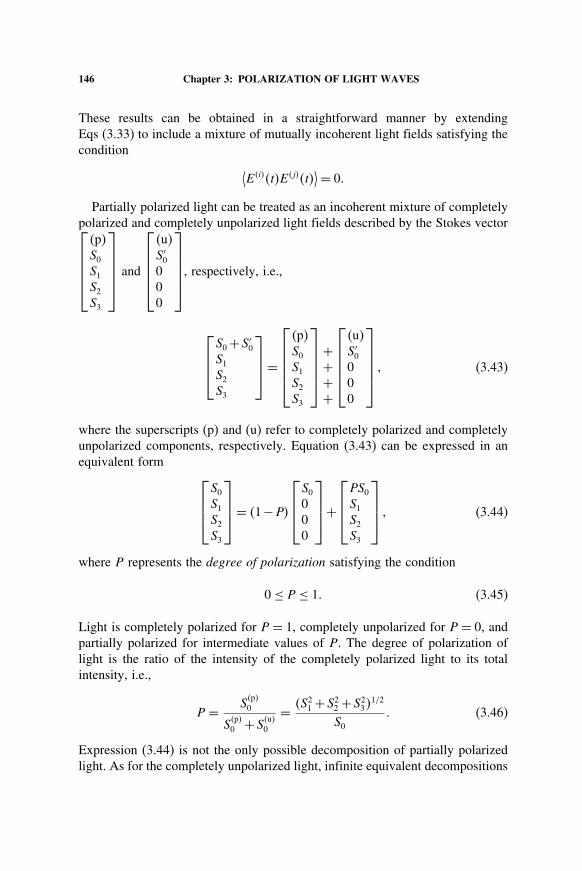
Partially polarized light can be treated as an incoherent mixture of completelypolarized and completely unpolarized light fields described by the Stokes vector⎡⎢⎢⎢⎢⎣
�p�S0
S1
S2
S3
⎤⎥⎥⎥⎥⎦
and
⎡⎢⎢⎢⎢⎣
�u�S′
0
000
⎤⎥⎥⎥⎥⎦
, respectively, i.e.,
⎡⎢⎢⎣
S0 +S′0
S1
S2
S3
⎤⎥⎥⎦=
⎡⎢⎢⎢⎢⎣
�p�S0
S1
S2
S3
⎤⎥⎥⎥⎥⎦
++++
⎡⎢⎢⎢⎢⎣
�u�S′
0
000
⎤⎥⎥⎥⎥⎦
� (3.43)
where the superscripts (p) and (u) refer to completely polarized and completelyunpolarized components, respectively. Equation (3.43) can be expressed in anequivalent form
⎡⎢⎢⎣
S0
S1
S2
S3
⎤⎥⎥⎦= �1−P�
⎡⎢⎢⎣
S0
000
⎤⎥⎥⎦+
⎡⎢⎢⎣
PS0
S1
S2
S3
⎤⎥⎥⎦ � (3.44)
where P represents the degree of polarization satisfying the condition
0 ≤ P ≤ 1� (3.45)
Light is completely polarized for P = 1, completely unpolarized for P = 0, andpartially polarized for intermediate values of P. The degree of polarization oflight is the ratio of the intensity of the completely polarized light to its totalintensity, i.e.,
P = S�p�0
S�p�0 +S
�u�0
= �S21 +S2
2 +S23�1/2
S0
� (3.46)
Expression (3.44) is not the only possible decomposition of partially polarizedlight. As for the completely unpolarized light, infinite equivalent decompositions

3.4: THE STOKES PARAMETERS 147
of partially polarized light in terms of orthogonal but mutually incoherent polar-ization states exist,
⎡⎢⎢⎣
S0
S1
S2
S3
⎤⎥⎥⎦= 1+P
2P
⎡⎢⎢⎣
PS0
S1
S2
S3
⎤⎥⎥⎦+ 1−P
2P
⎡⎢⎢⎣
PS0
−S1
−S2
−S3
⎤⎥⎥⎦ � (3.47)
We note in passing that Stokes parameters cannot describe superposition ofmutually coherent light fields.
3.4.5 Geometrical Interpretation of Stokes Parameters
The Stokes parameters of completely polarized light can be expressed in a formthat makes S1, S2, S3 appear as the Cartesian components of S0, treated as apolar vector (Fig. 3.7).
The parameter S2 can be expressed as
S2 = 2xy cos �0 = �2x −2
y�2xy
2x −2
y
cos �0 = S1 tan 2�� (3.48a)
S1
S3
S2
ψ2
χ2
P’
90−2χS0
P
O
x
y
z
Fig. 3.7: Stokes parameters S1, S2, S3 as Cartesian components of Stokes param-eter S0 for perfectly polarized light.

148 Chapter 3: POLARIZATION OF LIGHT WAVES
where tan 2� has already been defined (Eq. 3.9). Similarly, the parameter S3
may be written as
S3 =2xy sin�−�0� = 2S0
x√2
x +2y
y√2
x +2y
sin�−�0�
=S0 sin 2� sin�−�0� = S0 sin 2�� (3.48b)
The angles � and � have been defined in Eq. (3.16). Substituting Eqs (3.48) intoEq. (3.35) and solving for S1 and S2 gives
S1 =S0 cos 2� cos 2� = S0 sin�90−2�� cos 2�� (3.49a)
S2 =S0 cos 2� sin 2� = S0 sin�90−2�� sin 2�� (3.49b)
S3 =S0 sin 2� = S0 cos�90−2��� (3.49c)
The above equations bear close resemblance to the relationships among theCartesian and spherical polar components of the position vector:
x = r sin � cos ��
y = r sin � sin ��
z = r cos ��
This comparison is complete if the azimuthal angle � is identified with twice theinclination angle � of the polarization ellipse and the polar angle � is replacedby the complement of twice the angle of ellipticity �. This is shown in Fig. 3.7.
3.5 THE POINCARÉ SPHERE
We have seen in Section 3.4 how the Stokes parameters S1, S2, and S3 of com-pletely polarized light can be formally treated as Cartesian components of theStokes parameter S0, treated as a three-dimensional polar vector. Stokes param-eters of partially polarized light are related through the inequality of Eq. (3.38).We now develop a geometrical representation for the states of polarization oflight. This will be done with the help of the Poincaré sphere which was intro-duced in 1892 by H. Poincaré in a related but somewhat different context. ThePoincaré sphere is a sphere of unit radius in a space spanned by the normalizedStokes parameters �1 = S1/S0, �2 = S2/S0, and �3 = S3/S0 (Fig. 3.8).
It follows from the construction that each point on the surface of the Poincarésphere represents a unique state of polarization (S1, S2, S3) and vice versa. A point

3.5: THE POINCARÉ SPHERE 149
σ1= 1 S S0
σ2= 2 S S0
σ3= 3 S S0
P 4 χ2ψ2
P 3
P2
S0
1
S
O−1 1P 1
−1
N
1
−1
P
Fig. 3.8: Representation of states of polarization of perfectly polarized light onthe Poincaré sphere of unit radius, N is north pole, S is south pole.
such as P on the Poincaré sphere can be located in terms of the angles of longitude�2�� and latitude �2��, where angle � gives the orientation of the polarizationellipse with respect to the reference axes and � determines the ellipticity of thepolarization ellipse (Fig. 3.3e) and the sense of rotation of the electric vector. Apoint on the Poincaré sphere with coordinates (�1��2��3) represents the mostgeneral (elliptical) state of polarization of completely polarized light. Points onthe equator (zero latitude) with � = 0 and hence �3 = 0 represent all possiblestates of linearly polarized light.The horizontal state of polarization is represented by point P1 with coordinates⎡⎣
100
⎤⎦ on the Poincaré sphere. This is the point of intersection of the increas-
ing direction of the S1/S0 axis with the Poincaré sphere. Vertical polarization
corresponds to point P2 on the Poincaré sphere with coordinates
⎡⎣
−100
⎤⎦. Points
P3 and P4 represent ±45�-polarization states, respectively. The remaining statesof linear polarization are represented by points on the equator of the Poincaré

150 Chapter 3: POLARIZATION OF LIGHT WAVES
sphere with coordinates
⎡⎣
cos 2�sin 2�0
⎤⎦, where − ≤ 2� ≤ +. We recall that the
horizontal and vertical states are orthogonal states of polarization. The pointsP1 and P2 on the Poincaré sphere therefore represent a pair of orthogonal statesof polarization. It is no coincidence that the signs of the coordinates of pointP2 on the Poincaré sphere are opposite to the signs of the coordinates of pointP1. In fact, all pairs of orthogonal states of polarization share this property andare represented on the Poincaré sphere by diametrically opposite points. Allpoints on the Northern Poincaré hemisphere (with positive S3 and hence neg-ative �0) represent right elliptical states of polarization with the exception ofthe points on the equator where the ellipse degenerates into lines and the Northpole ��0 = −/2�� = /4� x = y� which represents the state of right circularpolarization. Similarly, it can be argued that points on the Southern Poincaréhemisphere represent left elliptical polarization states with the South pole rep-resenting the left circular polarization. Points lying on a given latitude (constant2�) represent all elliptical polarization states for which the polarization ellipsemaintains its shape but the orientation of its major axis with respect to the hori-zontal direction takes all possible values. Putting it differently, a given latituderepresents all polarization states generated by the rotation of the polarizationellipse of a definite ellipticity about the direction of propagation of the wave.A similar statement can be made for points lying on a given longitude (merid-ian). In this case the orientation of the polarization ellipse with respect to thehorizontal direction does not change, but the aspect ratio �y/x� goes throughall values between zero and infinity. Partially polarized light can be representedby a point inside the Poincaré sphere such that the distance �
S21+S2
2+S23
S20
�1/2 of thepoint from the center of the Poincaré sphere gives the degree of polarization P.The center of the Poincaré sphere represents completely unpolarized light. Inconclusion, it can be said that all possible states of polarization of light can beenvisioned on or within the surface of the Poincaré sphere.
3.6 MUELLER MATRICES
We have described polarization states of completely or partially polarized lightin terms of the Stokes vectors. The state of polarization of light can be changedby interposing polarizing elements in its path. The action of a polarizing elementcan be described by the matrix equation
⎡⎢⎢⎣
S′0
S′1
S′2
S′3
⎤⎥⎥⎦=
⎡⎢⎢⎣
M11 M12 M13 M14
M21 M22 M23 M24
M31 M32 M33 M34
M41 M42 M43 M44
⎤⎥⎥⎦
⎡⎢⎢⎣
S0
S1
S2
S3
⎤⎥⎥⎦ � (3.50)
3.6: MUELLER MATRICES 151
where
⎡⎢⎢⎣
S0
S1
S2
S3
⎤⎥⎥⎦ and
⎡⎢⎢⎣
S′0
S′1
S′2
S′3
⎤⎥⎥⎦ are the initial and final Stokes vectors, respectively,
of completely or partially polarized light. The 4×4 transformation matrix M iscalled the Mueller matrix. We now develop Mueller matrices for linear polarizersand phase retarders.
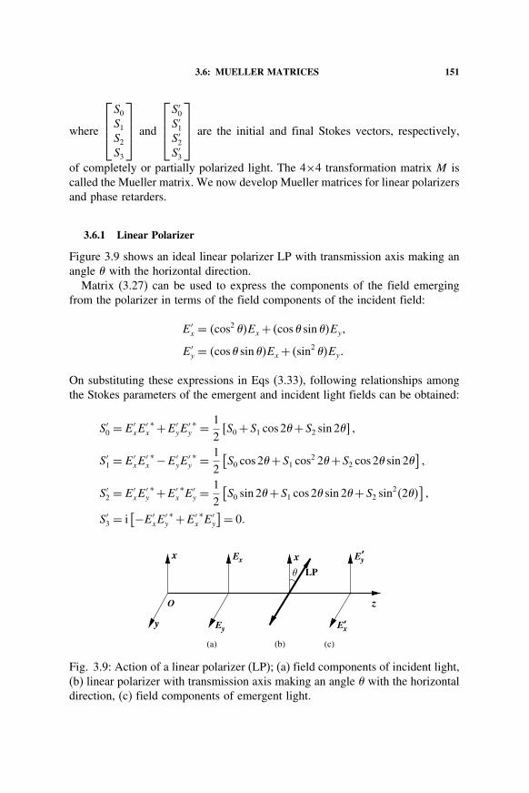
3.6.1 Linear Polarizer
Figure 3.9 shows an ideal linear polarizer LP with transmission axis making anangle � with the horizontal direction.
Matrix (3.27) can be used to express the components of the field emergingfrom the polarizer in terms of the field components of the incident field:
E′x = �cos2 ��Ex + �cos � sin ��Ey�
E′y = �cos � sin ��Ex + �sin2 ��Ey�
On substituting these expressions in Eqs (3.33), following relationships amongthe Stokes parameters of the emergent and incident light fields can be obtained:
S′0 = E′
xE′x∗ +E′
yE′y∗ = 1
2�S0 +S1 cos 2� +S2 sin 2� �
S′1 = E′
xE′x∗ −E′
yE′y∗ = 1
2
[S0 cos 2� +S1 cos2 2� +S2 cos 2� sin 2�
]�
S′2 = E′
xE′y∗ +E′
x∗E′
y = 12
[S0 sin 2� +S1 cos 2� sin 2� +S2 sin2�2��
]�
S′3 = i
[−E′xE
′y∗ +E′
x∗E′
y
]= 0�
Ex’yE
Ex’Ey
LP
zO
x
y
θ
(a) (c)(b)
x
Fig. 3.9: Action of a linear polarizer (LP); (a) field components of incident light,(b) linear polarizer with transmission axis making an angle � with the horizontaldirection, (c) field components of emergent light.

152 Chapter 3: POLARIZATION OF LIGHT WAVES
Expressing these results in the matrix form, we have⎡⎢⎢⎣
S′0
S′1
S′2
S′3
⎤⎥⎥⎦= M���
⎡⎢⎢⎣
S0
S1
S2
S3
⎤⎥⎥⎦ � (3.51)
where the matrix
M��� = 12
⎡⎢⎢⎣
1 cos 2� sin 2� 0cos 2� cos2 2� cos 2� sin 2� 0sin 2� cos 2� sin 2� sin2 2� 00 0 0 0
⎤⎥⎥⎦ (3.52a)
is the Mueller matrix representing the action of an ideal linear polarizer orientedat an angle � with respect to the horizontal direction. Mueller matrices for somespecific values of angle � are given below.
M�0�� = 12
⎡⎢⎢⎣
1 1 0 01 1 0 00 0 0 00 0 0 0
⎤⎥⎥⎦ � (3.52b)
M�90�� = 12
⎡⎢⎢⎣
1 −1 0 0−1 1 0 00 0 0 00 0 0 0
⎤⎥⎥⎦ � (3.52c)
3.6.2 Phase Retarder
The transformation
E′x = Exei�x�
E′y = Eyei�y
describes the action of a phase retarder with its slow and fast axes coincidingwith the x, y axes (Eq. 3.29a). The corresponding transformation
S′0 = S0�
S′1 = S1�
S′2 = S2 cos �0 −S3 sin �0�
S′3 = S2 sin �0 +S3 cos �0�
(3.53)

3.7: THE COHERENCY MATRIX 153
of the Stokes parameters yields
M�PR� =
⎡⎢⎢⎣
1 0 0 00 1 0 00 0 cos �0 − sin �0
0 0 sin �0 cos �0
⎤⎥⎥⎦ (3.54a)
as the Mueller matrix for the phase retarder. The Mueller matrices for the quarter(�0 = ±90�) and half (�0 = ±180�) wave plates are
M�QWP� =
⎡⎢⎢⎣
1 0 0 00 1 0 00 0 0 ∓10 0 ±1 0
⎤⎥⎥⎦ � (3.54b)
M�HWP� =
⎡⎢⎢⎣
1 0 0 00 1 0 00 0 −1 00 0 0 −1
⎤⎥⎥⎦ � (3.54c)
respectively.
3.7 THE COHERENCY MATRIX
There is yet another scheme to describe the states of polarization of light,completely or partially polarized. This scheme is based on Wolf’s 2×2 coherencymatrix
J =[
Jxx Jxy
Jyx Jyy
]� (3.55)
Following Born and Wolf, the elements of the coherency matrix defined in termsof the time averaged field products are
Jxx = Ex�t�E∗x�t��� (3.56a)
Jxy = Ex�t�E∗y �t��� (3.56b)
Jyx = Ey�t�E∗x�t��� (3.56c)
Jyy = Ey�t�E∗y �t��� (3.56d)

154 Chapter 3: POLARIZATION OF LIGHT WAVES
A comparison of Eqs (3.37) and (3.56) gives
Jxx = 12
�S0 +S1�� (3.57a)
Jxy = 12
�S2 − iS3�� (3.57b)
Jyx = 12
�S2 + iS3�� (3.57c)
Jyy = 12
�S0 −S1�� (3.57d)
For horizontally polarized light, Jxx = S0, Jxy = 0, Jyx = 0, Jyy = 0, so that thecoherency matrix for the horizontally polarized light of unit irradiance takes theform
J�H� =[
1 00 0
]� (3.58a)
The coherency matrices for some other states of polarization are given below:
J�±45�� = 12
[1 ±1±1 1
]� (3.58b)
J�V� =[
0 00 1
]� (3.58c)
J�RCP� = 12
[1 i−i 1
]� (3.58d)
J�LCP� = 12
[1 −ii 1
]� (3.58e)
For completely unpolarized light with
Ex2 = Ey2 = S0/2� S1 = S2 = S3 = 0�
the coherency matrix for unit light irradiance is
J�un� = 12
[1 00 1
]� (3.58f)
The coherency matrix approach is capable of describing the states of polarizationof partially polarized light and of light which may be a mixture of incoherentlight fields.

3.8: PANCHARATNAM THEOREM 155
3.8 PANCHARATNAM THEOREM
During his investigations on how interfering beams with non-orthogonal statesof polarization can have the same phase, Pancharatnam at the age of 22 proveda remarkable theorem called the Pancharatnam theorem [3.8]. If the state ofpolarization of a light beam is changed in a cyclic manner so that at the endof the cycle the light beam is once again in its initial state of polarization, thenaccording to this theorem, the light wave may pick up an additional phase duringthe cycle which is not accounted for by the path differences, if any, involved inthe process. This phase called Pancharatnam–Berry phase is purely geometricalin nature. The actual change in the phase depends on the intermediate states ofpolarization that the light beam is made to go through. Pancharatnam theoremcan be best illustrated with reference to the Poincaré sphere (Fig. 3.10). Werecall that each point on the surface of the Poincaré sphere represents a uniquestate of polarization of completely polarized light. Consider a closed path Csuch as the path ABDA traced on the surface of the Poincaré sphere. Thelight beam returns to its original state of polarization represented by point Aafter undergoing changes in its polarization indicated by the path. On returnto the initial state of polarization, the phase of the light wave changes by anamount equal to half the solid angle subtended by the closed path (the sphericaltriangle ABD in the present example) at the center of the Poincaré sphere. Ifthe cyclic changes are made along a path that subtends zero solid angle at thecenter, the light beam undergoes no phase change. The phase change predictedby Pancharatnam has been verified by Pancharatnam himself and by others.For more details, the reader is referred to Fundamentals of Polarized light byBrosseau [3.3].
σ1
σ2
3σ
O
A
DB
C
Fig. 3.10: Poincaré Sphere and Pancharatnam Theorem.