policy: eng-es-001 requirements for subdivision … works... · rural road design ... street (road)...
TRANSCRIPT

Responsible Officer: Director Engineering Services Version: 2.00
Adopted: 26 May 2008 Last Revised: 22 November 2010
Distribution: City of Kalgoorlie-Boulder Website, Policy Register
Last printed: 1 September 2014 Page: 1 of 42
Uncontrolled document when printed
POLICY: ENG-ES-001
Requirements for Subdivision Policy
Purpose
Developers of new subdivisions within the City of Kalgoorlie-Boulder are required to
adhere to the “City of Kalgoorlie-Boulder Requirements for Subdivision Development”
document.
This is to ensure that Subdivision development within the City of Kalgoorlie-Boulder is to
the required standard to service the needs of residents both functionally and structurally.
Definitions
The terms ‘Council’s Engineer’ or ‘Engineer’ shall mean the Director Engineering Services
(or his representative) or an Engineer or firm of Consulting Engineers (or their
representatives) appointed by Council from time to time to act on his behalf.
The term ‘Subdivider’ or ‘Developer’ shall mean the owner of the land proposed to be
subdivided and developed.
The term ‘Consulting Engineer’ or ‘Consultant’ shall mean the Engineer appointed by the
Subdivider to design, document and superintend construction of the works.
The term ‘Superintendent’ means the person employed to oversee the progress and
standard of site works. Generally this position is filled by the consultant employed by the
developer.
The term ‘Contractor’ shall mean the person or company employed by the Subdivider to
execute the construction works.
The term ‘street’ shall have the same meaning as the definition of the term contained in
the Local Government Act 1995 which reads:-
ENG-ES-001 Requirements for Subdivision
“‘Street’ includes a highway; and a thoroughfare; which the public are allowed to use; and
includes every part of the highway or thoroughfare, and other things including bridges and
culverts, appurtenant to it.”
‘Road’ has the same meaning as ‘street’.
The meaning of all the other terms not specifically defined in this document shall be the
same as the definitions contained in the Local Government Act 1995.
Statement
1. Scope
These subdivisional development guidelines have been developed by City’s Engineering
Department as a reference guide for developers, planners, engineers, and contractors
involved in subdivisional design and construction. They shall be interpreted as setting out
the requirements which will be accepted by Council in granting clearance of the
engineering conditions imposed on a subdivision.
2. General Requirements
2.1. Where proposals for the subdivision of land in a district include the provision
of streets for the use by the public, and the proposals have been approved,
the owner of the land shall not dispose of it, or part of it or an estate or interest
in it, until he has caused those streets to be constructed and drained to the
satisfaction of the Council (Section 295 (4) (a) Local Government Act).
2.2. Any streets and/or drains required to be constructed under the preceding
section of the Local Government Act, shall be constructed to Council’s
requirements.
2.3. Where proposals for the subdivision of land in a district include the provision
of a sewerage reticulation, the sewerage reticulation system shall be gravity
type designed and constructed in accordance with Volume One of the Water
Corporation of Western Australia’s sewerage manual. Where it is not possible
to service the subject land using gravity sewers, rising mains shall be
designed and constructed with Council approval to Council’s requirements.
2.4. Technical provisions included in these requirements are intended to provide a
guide to the standard of work, materials and design required before streets,
drains and sewerage systems will be certified to the Western Australian
Planning Commission as having been made to the satisfaction of the Council.
They are not necessarily complete and are not intended to be used as a
ENG-ES-001 Requirements for Subdivision
specification or contract for construction. They may be subject to alteration
with the approval of the Engineer.
2.5. The Local Government Act 1995, Section 295(6) reads as follows:
(a) Where a person who is subdividing land is by the provisions of this
Part required to construct and drain streets shown in the plan of
subdivision he may-
i) carry out or cause to be carried out the construction and
drainage at his own cost and expense; or
ii) arrange for the Council to carry out the work on his behalf and
at his cost and expense.
(b) The fees are as follow in accordance with the Council’s
requirements:-
(Council’s Resolution of 13 Dec 1993)
Where the person does not make the arrangements with Council, he
shall pay to it, on demand, an amount to cover the reasonable costs
of the Council in supervising the construction and drainage which
amount shall be reckoned as follows:-
i) where the person has not engaged a Consulting Engineer and
Clerk of Works to design and supervise the construction and
drainage the amount shall be three percentum of the costs of
the construction and drainage as estimated by the Council;
ii) where the person has employed a Consulting Engineer and
Clerk of Works to design and supervise the construction and
drainage, the amount shall be one and one-half precent of the
cost of the construction and drainage as estimated by Council;
iii) A sewerage headworks contribution shall be paid by the
subdivider to the Council before construction commences. The
amount of the payment shall be based on the headworks
ENG-ES-001 Requirements for Subdivision
charges levied by the Water Corporation of WA for new sewer
connections (ref Cl 6.3).
2.6. The design, preparation of drawings and specifications, and supervision of
construction of subdivision works covered by these requirements shall be
undertaken by a Consulting Engineer who is eligible for corporate membership
of the Institution of Engineers Australia or registered in the National
Professional Engineers Register(NPER).
2.7. The supervision fee referred to in Section 295 (6) (b) of the Local Government
Act shall be paid to Council before construction commences - refer to Clause
6.2 for details.
2.8. Drawings and specifications for the construction of streets and drains shall be
prepared in accordance with Clause 4 of these requirements and must be
approved by Council’s Engineer before any work will be allowed to
commence.
2.9. The detail contained in the drawings and specifications for the gravity
sewerage system shall be in accordance with the requirements of Volume
One of the Water Corporation of Western Australia’s Sewerage Manual. The
required detail may be incorporated in the drawings called for in Clause 2.9.
2.10. All construction work shall be carried out in accordance with the approved
drawings and specifications and shall be subject to inspection at various
stages of the works by Council’s Engineer. Final approval of the works shall
only be given when the whole of the works have been constructed to the true
meaning and intent of the approved drawings and specifications and to the
satisfaction of Council’s Engineer.
2.11. Council’s Engineer will direct all notices, requests, instructions and approvals
to the Consulting Engineer, except in urgent circumstances when they may be
given directly to other parties involved in the subdivision.
2.12. After clearance of deposited plans by the Western Australian Planning
Commission and the Department of Land Information, any land delineated
and shown as a new street on such diagrams shall then be under the control
of Council subject to the maintenance requirements referred to in Section 6.
2.13. Council is conscious of the need to preserve natural vegetation wherever
possible in subdivisions. To this end Council may impose special conditions
on particular subdivisions to minimise the environmental impact of street,
drainage and sewerage construction, particularly in relation to preservation of
ENG-ES-001 Requirements for Subdivision
established trees within road reserves. Subdividers should be conscious of
these aims and should take them into consideration in the various stages of
planning for a subdivision.
2.14. Road upgrading conditions of subdivision
When a planned subdivision shows the joining of a subdivision road with an
existing public road or roads, that existing road (or roads) shall be upgraded in
accordance with these Subdivision Requirements and to the satisfaction of the
City’s Engineer, if it is considered to be substandard or inadequate to
accommodate the expected additional traffic generated by the subdivision.
In cases where the whole road requires upgrading as a condition of
subdivision and the development is located on one side of the road only, the
cost of this work shall generally be shared in accordance with a negotiated
cost share agreement between the City and the developer.
When it is impractical to physically construct/upgrade the road or part thereof,
the Developer shall lodge with the City, a non-refundable cash contribution
equal to the cost of the proposed roadworks as estimated by the City.
2.15. Provision of adequate traffic management devices
The Developer should undertake traffic studies and provide adequate
intersection treatment (roundabout or traffic lights) if needed.
2.16. Underground power
Underground power reticulation is required as a mandatory condition of
subdivision in all new urban residential subdivisions of standard design.
3. DESIGN AND CONSTRUCTION CRITERIA
3.1. General
Criteria provided here are minimum criteria only and are necessarily broad
based to cover general subdivision situations. In particular situations
amendments may be required and Council may impose special conditions not
covered by the criteria.
ENG-ES-001 Requirements for Subdivision
3.2. Roads
3.2.1 General
Roads should generally be designed in accordance with relevant
Austroads (NAASRA) and ARRB guidelines and publications which
include:-
Guide to Traffic Engineering Practice – Parts 1 to 14 (Austroads)
Turning Path Templates (Austroads, 1995)
Sealed Local Roads Manual (ARRB)
Guide for the design of Typical Urban Intersections
Guide Policy for the Geometric Design of Major Urban Roads
(NAASRA, 1976)
Rural Road Design – Guide to the Geometric Design of Rural
Roads (Austroads, 1989)
Policy for Installations of Public Utility Authorities within the Road
Reserve
Pavement Design – A guide to the Structural Design of Road
Pavements (Austroads 1995)
Guidelines for the Design of Bicycle facilities (Bikewest)
Street (Road) Lighting Code AS 1158
However, consideration must be given to the final aesthetic and
functional aspects of the area. Aspects to be considered include
minimising the environmental impact (particularly regarding existing
trees and vegetation), fitting road grades as close to existing contours
as practicable and provision of lot access.
ENG-ES-001 Requirements for Subdivision
The designation of which road types shall apply to a particular
subdivision (i.e. townsite residential, rural, special rural or industrial)
shall be at the discretion of the Council and the Subdivider shall comply
with the requirements for those designations.
3.2.2 Townsite Residential Roads
Local distributors: sealed and kerbed to minimum 7.4m width with
embayment for bus stops or wider if so directed by Council.
Access roads: sealed and kerbed to minimum 6.0m width where no
more than 100 lots are serviced or wider if so directed by Council.
Seal is to comprise minimum 25mm thick asphalt over a 7mm
primerseal. Asphalt thickness at intersections with local distributor or
arterial roads is to comprise 40mm thick intersection mix.
Council may, at its discretion, allow construction of un-kerbed roads, in
which case shoulders and table drains shall be provided as for rural
roads.
The maximum longitudinal grade of a road shall be 10% unless
otherwise approved. The minimum longitudinal grade shall be 0.5%. A
vertical curve shall be provided when the grade change is 1% or greater.
One-way crossfall to a maximum of 3% may be approved for access
roads when excessive crossfall exists in the natural surface. Roads
shall normally have two-way crossfalls of 3% except where geometric
design requirements dictate that super-elevation is required.
Verges shall have sufficient width for the provision of trunk and
reticulation services and property connections, and shall be a minimum
of 5.0m unless noted otherwise. In areas where no more than 20
residential properties are serviced by a cul-de-sac, the minimum width
may be reduced to 4.0m at the discretion of the City’s Engineer if the
following conditions are satisfied:-
Sewers are laid at the rear of the lots
ENG-ES-001 Requirements for Subdivision
The lots are serviced by underground power reticulation
Verge trees are not planted
Verges shall normally be graded at +1% from the top of the kerb to the
property boundary. In areas of steep crossfall or where earthworks
should desirably be reduced to minimise environmental impact, the
verge grading may be increased as agreed with Council’s Engineer.
Cul-de-sac heads shall have a minimum head radius of 9m to edge of
seal with 15m radius tapers.
Kerb type shall be mountable to residential frontages and barrier or
semi-barrier elsewhere.
Traffic control devices, sign posts, guide posts, street nameplates, guide
signs and warning signs shall be provided in accordance with AS 1742
to the satisfaction of Council’s Engineer.
Refer to Clause 3.7 for pavement design and make-up.
Eyebrow Treatments
Eyebrow treatments shall be provided at right angle bends on roads
where lot boundaries and frontages are arranged in such a manner as to
create an irregular verge area.
3.2.3 Industrial Roads
In industrial areas roads shall be sealed and kerbed to a minimum width
of 9m unless otherwise directed by Council. All other design criteria
shall be in accordance with the requirements for townsite residential
roads with the following exceptions;
Cul-de-sacs shall be avoided where possible to avoid vehicle
turning problems. Otherwise the minimum radius shall be 12m with
20m radius transition.
Kerb type to be semi-mountable throughout industrial roads.
ENG-ES-001 Requirements for Subdivision
All industrial roads shall be designed for particular vehicles (eg
roadtrains) to satisfy access in accordance with Council’s
Roadtrain/Heavy Haulage Policy.
3.2.4 Rural Roads
Rural roads and roads servicing special rural or semi-rural areas shall
comply with the following criteria:
Arterial roads: minimum sealed width 7.4m (dependent on design traffic
volumes in 20 years) with 1.5m compacted gravel shoulders with
embayment for bus stops, in a road reserve of sufficient width to allow
for future widening beyond the 20 year design period;
Collector roads: minimum sealed width 7.4m with 1.3m compacted
gravel shoulders;
Access roads: minimum sealed width 6.0m with 1.3m compacted gravel
shoulders where no more than 80 lots are serviced.
Geometric design shall be according to “Rural Road Design”, Austroads
1993 or its latest revision. The minimum design speed for access roads
shall be 60 km/h, collector roads 70 km/h and arterial roads 90 km/h.
The maximum longitudinal grade of a road shall be 10% unless
otherwise approved. The minimum longitudinal grade shall be 0.5%
unless table drains are graded independently of the road to provide
satisfactory drainage, where necessary. A vertical curve shall be
provided when the grade change is 1% or greater.
One-way crossfall to a maximum of 3% may be approved for access
roads when excessive crossfall exists in the natural surface. Roads
shall normally have two-way crossfalls of 3% where geometric design
requirements dictate that super-elevation is required.
Table drains shall be provided for all roads for a minimum width of 1.2m
at a slope of 1 in 3 (33%).

ENG-ES-001 Requirements for Subdivision
Cut batters shall generally be no steeper than 1 in 3 (33%) except in
hilly terrain, or where depth of cut is considerable, or where ground
conditions are such that it is not practical to comply with this requirement
without excessive cost or environmental disturbance. Then, subject to
the approval of Council’s Engineer, slope of cut batters may be
increased to a maximum of 1 in 1 (100%). Fill batters shall generally be
no steeper than 1 in 4 (25%) except in hilly terrain or where fill heights
are considerable, in which case a maximum slope of 1 in 2 (50%) may
be used subject to the approval of Council’s Engineer.
Verges shall have sufficient width to install public utility services (refer Cl
3.2.2). In particular sufficient width must be provided to install overhead
power lines with poles located at least 2.5m from the invert to the table
drain.
Roads shall be designed to enable access to lots at an absolute
maximum grade of 16%.
Cul-de-sac heads shall have a minimum head radius of 9m to edge of
seal, with 15m radius tapers.
Intersection of collector/access and access/access roads shall be
widened as follows:
Terminating roads shall be widened to at least 7.4m seal width for
a straight length of 10m from the tangent point of the turn-out
radius, and then tapering to the normal seal width over an
additional 10m length;
Through roads shall be widened by at least 1m on the side of the
terminating road only for a straight length of 10m each side of the
turn-in radii, and then tapering to the normal seal width over an
additional 10m length.
Intersections of collector/access roads shall have culverts installed
under roads as required by the City’s Engineer.
ENG-ES-001 Requirements for Subdivision
Intersections of collector/arterial roads shall be subject to approval of
Council’s Engineer. All such intersections shall be surfaced with
minimum 40mm thick intersection mix over a 7mm bituminous
primerseal.
All intersections shall be kerbed extending for a minimum length of 10m
each side of intersection radii.
Underground drainage systems including culverts and side entry pits, if
required, shall be installed at the intersections of Collector/Arterial roads
as required by the City’s Engineer.
Traffic control devices, sign posts, guide posts, street nameplates, guide
signs and warning signs shall be provided in accordance with AS 1742
to the satisfaction of Council’s Engineer.
Refer to Section 3.7 for pavement design and make-up.
3.2.5 Public Utility Conduits
The Consultant shall ascertain the need for conduits under roads for all
public utility services for both present and future services. If the Public
utility authority concerned will not install conduits at the time of
construction of the roads, then the conduits shall be installed by the
Subdivider (prior to surfacing the roads) whether or not the conduits are
immediately required. Backfill trenches for conduits with compacted
cement stabilised sand as detailed for stormwater pipeline systems in
Section 3.9.6.
3.3 Survey Set Out
Subdivider shall arrange at his/her cost, for a licensed surveyor to carry out
the survey set out works in accordance with the approved drawings.
The Subdivider shall be responsible for the accuracy of the setting out works.
3.4 Clearing and Stripping
ENG-ES-001 Requirements for Subdivision
Clearing and stripping for roads shall only be to the minimum extents
necessary to accommodate the works and services. Any clearing beyond
necessary limits shall be rehabilitated at the Subdivider’s expense.
Topsoil shall be stockpiled for later re-spreading on batters and other
disturbed surfaces where appropriate.
Material from clearing shall be disposed of away from the site of the works in a
place and manner approved by Council. No material from clearing shall be
deposited within the road reserve or on property beyond the boundaries of the
subdivision without the owner’s permission.
Adequate precautions must be taken to ensure no damage occurs to trees,
vegetation, fences, and services and protect other installations outside the
designated areas of the works. Survey pegs or marks which are disturbed
shall be reinstated by a licensed surveyor at the Subdivider’s expense.
3.5 Earthworks
Earthworks shall be performed in a safe manner. No material shall be
obtained from borrow pits within road reserves and no excess material shall
be disposed of in road reserves.
All fill shall be clean, granular material obtained from general and roadworks
excavations and shall not be contaminated with roots or other impurities. The
fill shall be placed in even layers not greater than 300mm thick and each layer
shall be compacted to at least 93% of the modified maximum dry density
(MMDD) of the material.
3.6 Subgrade and foundation preparation
If, after excavation to subgrade level it is apparent that subgrades differ from
those on which the pavement design is based, then the pavement shall be
redesigned or unstable subgrade material shall be removed and replaced with
approved imported fill material.
After clearing and topsoil stripping and excavation to subgrade level, compact
subgrades and foundations of embankments to at least 93% of modified
ENG-ES-001 Requirements for Subdivision
maximum dry density of the material for a depth of not less than 300mm.
Alternatively method compaction of the surface may be acceptable depending
on the materials.
3.7 Pavements
3.7.1 Pavement Design
Pavements shall generally be designed for a 25 year design life in
accordance with the publication ‘Pavement Design’ Austroads 1995 (or
its latest issue).
In all cases pavement design shall be based on the in situ subgrade
CBR, which shall be determined for each different subgrade type
expected to be encountered in the works. Determination of subgrade
CBR shall be by one of the methods nominated in the publication
‘Pavement Design’, i.e. by laboratory testing, or by field testing backed
up by limited laboratory tests. The Consultant shall adopt whatever test
procedures are necessary to provide an accurate assessment of
subgrade CBR for design purposes. Council’s Engineer may request
further field or laboratory testing at his discretion.
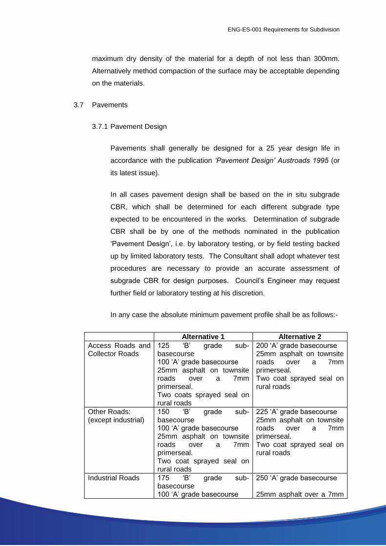
In any case the absolute minimum pavement profile shall be as follows:-
Alternative 1 Alternative 2
Access Roads and Collector Roads
125 ‘B’ grade sub-basecourse 100 ‘A’ grade basecourse 25mm asphalt on townsite roads over a 7mm primerseal. Two coats sprayed seal on rural roads
200 ‘A’ grade basecourse 25mm asphalt on townsite roads over a 7mm primerseal. Two coat sprayed seal on rural roads
Other Roads: (except industrial)
150 ‘B’ grade sub-basecourse 100 ‘A’ grade basecourse 25mm asphalt on townsite roads over a 7mm primerseal. Two coat sprayed seal on rural roads
225 ‘A’ grade basecourse 25mm asphalt on townsite roads over a 7mm primerseal. Two coat sprayed seal on rural roads
Industrial Roads 175 ‘B’ grade sub-basecourse 100 ‘A’ grade basecourse
250 ‘A’ grade basecourse 25mm asphalt over a 7mm
ENG-ES-001 Requirements for Subdivision
25mm asphalt over a 7mm primerseal.
primerseal
Intersections 40mm thick intersection mix asphalt at intersections involving industrial and or arterial or distribution roads.
Alternative pavement profiles giving equivalent load bearing capacities
will be considered. Council may, at its discretion, allow sprayed seal
surfacing in lieu of asphalt surfacing on townsite roads.
3.7.2 Basecourse Widths
On kerbed roads the width of basecourses shall equal the width of seal
plus 900mm. On un-kerbed roads the width of basecourses shall equal
the width of seal plus 600mm.
3.7.3 Shoulders
Shoulders shall be 75mm thick ‘A’ grade basecourse throughout on un-
kerbed roads. The edge of a shoulder shall commence from the edge of
the basecourses (not the edge of seal).
3.7.4 Compaction
All sub-basecourses, basecourses and shoulders shall be compacted
to at least 98% of the modified maximum dry density of the material.
3.7.5 Materials
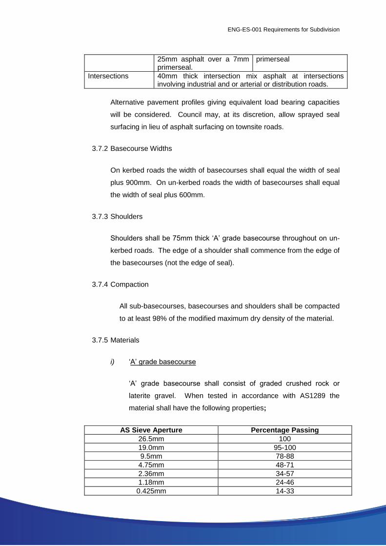
i) ‘A’ grade basecourse
‘A’ grade basecourse shall consist of graded crushed rock or
laterite gravel. When tested in accordance with AS1289 the
material shall have the following properties;
AS Sieve Aperture Percentage Passing
26.5mm 100
19.0mm 95-100
9.5mm 78-88
4.75mm 48-71
2.36mm 34-57
1.18mm 24-46
0.425mm 14-33
ENG-ES-001 Requirements for Subdivision
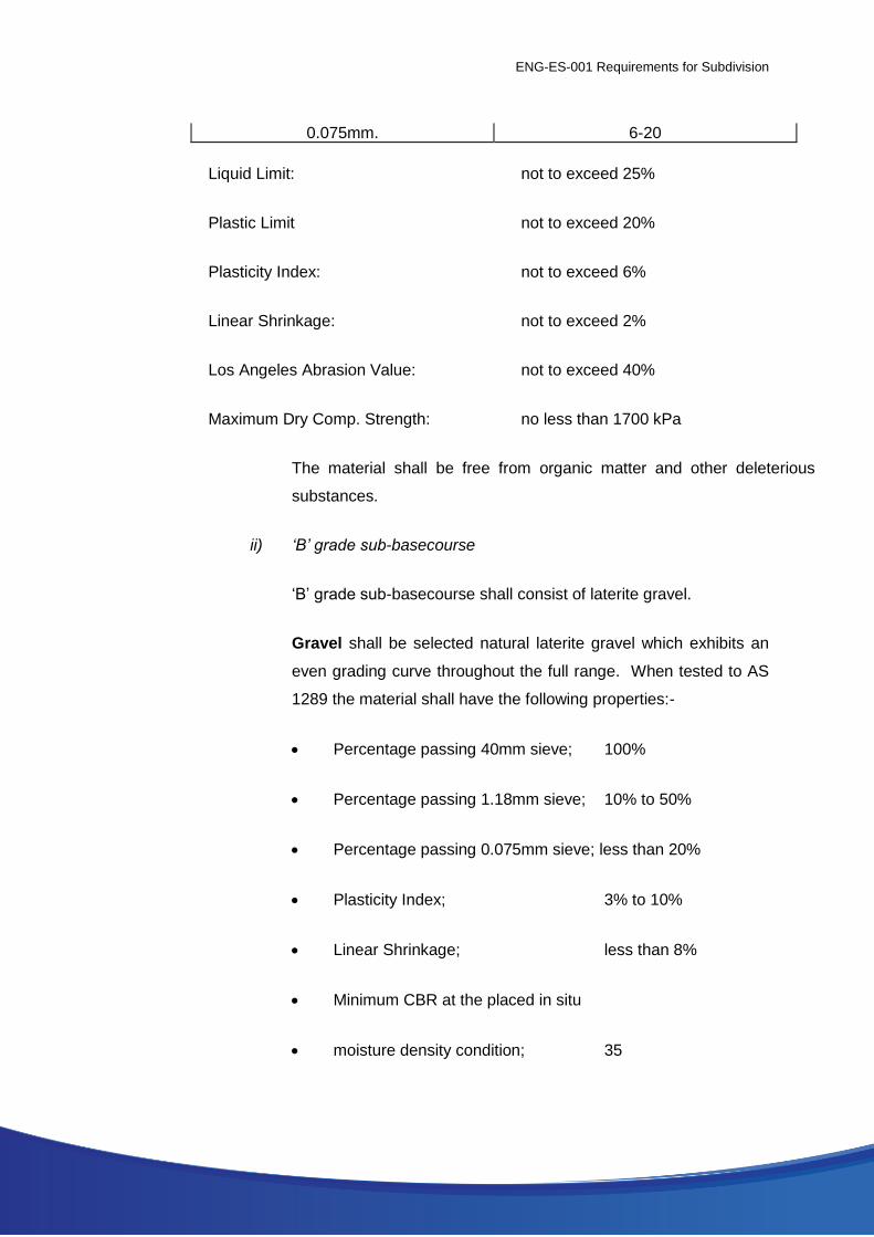
0.075mm. 6-20
Liquid Limit: not to exceed 25%
Plastic Limit not to exceed 20%
Plasticity Index: not to exceed 6%
Linear Shrinkage: not to exceed 2%
Los Angeles Abrasion Value: not to exceed 40%
Maximum Dry Comp. Strength: no less than 1700 kPa
The material shall be free from organic matter and other deleterious
substances.
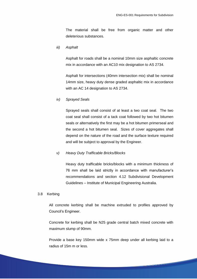
ii) ‘B’ grade sub-basecourse
‘B’ grade sub-basecourse shall consist of laterite gravel.
Gravel shall be selected natural laterite gravel which exhibits an
even grading curve throughout the full range. When tested to AS
1289 the material shall have the following properties:-
Percentage passing 40mm sieve; 100%
Percentage passing 1.18mm sieve; 10% to 50%
Percentage passing 0.075mm sieve; less than 20%
Plasticity Index; 3% to 10%
Linear Shrinkage; less than 8%
Minimum CBR at the placed in situ
moisture density condition; 35
ENG-ES-001 Requirements for Subdivision
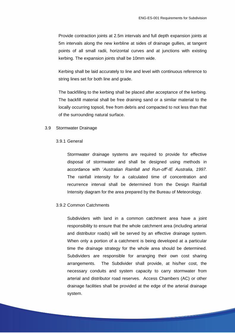
The material shall be free from organic matter and other
deleterious substances.
iii) Asphalt
Asphalt for roads shall be a nominal 10mm size asphaltic concrete
mix in accordance with an AC10 mix designation to AS 2734.
Asphalt for intersections (40mm intersection mix) shall be nominal
14mm size, heavy duty dense graded asphaltic mix in accordance
with an AC 14 designation to AS 2734.
iv) Sprayed Seals
Sprayed seals shall consist of at least a two coat seal. The two
coat seal shall consist of a tack coat followed by two hot bitumen
seals or alternatively the first may be a hot bitumen primerseal and
the second a hot bitumen seal. Sizes of cover aggregates shall
depend on the nature of the road and the surface texture required
and will be subject to approval by the Engineer.
v) Heavy Duty Trafficable Bricks/Blocks
Heavy duty trafficable bricks/blocks with a minimum thickness of
76 mm shall be laid strictly in accordance with manufacturer’s
recommendations and section 4.12 Subdivisional Development
Guidelines – Institute of Municipal Engineering Australia.
3.8 Kerbing
All concrete kerbing shall be machine extruded to profiles approved by
Council’s Engineer.
Concrete for kerbing shall be N25 grade central batch mixed concrete with
maximum slump of 90mm.
Provide a base key 150mm wide x 75mm deep under all kerbing laid to a
radius of 15m m or less.
ENG-ES-001 Requirements for Subdivision
Provide contraction joints at 2.5m intervals and full depth expansion joints at
5m intervals along the new kerbline at sides of drainage gullies, at tangent
points of all small radii, horizontal curves and at junctions with existing
kerbing. The expansion joints shall be 10mm wide.
Kerbing shall be laid accurately to line and level with continuous reference to
string lines set for both line and grade.
The backfilling to the kerbing shall be placed after acceptance of the kerbing.
The backfill material shall be free draining sand or a similar material to the
locally occurring topsoil, free from debris and compacted to not less than that
of the surrounding natural surface.
3.9 Stormwater Drainage
3.9.1 General
Stormwater drainage systems are required to provide for effective
disposal of stormwater and shall be designed using methods in
accordance with ‘Australian Rainfall and Run-off’-IE Australia, 1997.
The rainfall intensity for a calculated time of concentration and
recurrence interval shall be determined from the Design Rainfall
Intensity diagram for the area prepared by the Bureau of Meteorology.
3.9.2 Common Catchments
Subdividers with land in a common catchment area have a joint
responsibility to ensure that the whole catchment area (including arterial
and distributor roads) will be served by an effective drainage system.
When only a portion of a catchment is being developed at a particular
time the drainage strategy for the whole area should be determined.
Subdividers are responsible for arranging their own cost sharing
arrangements. The Subdivider shall provide, at his/her cost, the
necessary conduits and system capacity to carry stormwater from
arterial and distributor road reserves. Access Chambers (AC) or other
drainage facilities shall be provided at the edge of the arterial drainage
system.
ENG-ES-001 Requirements for Subdivision
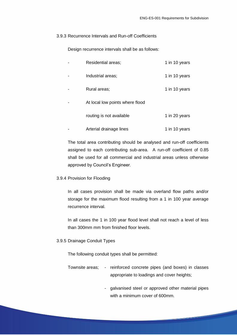
3.9.3 Recurrence Intervals and Run-off Coefficients
Design recurrence intervals shall be as follows:
- Residential areas; 1 in 10 years
- Industrial areas; 1 in 10 years
- Rural areas; 1 in 10 years
- At local low points where flood
routing is not available 1 in 20 years
- Arterial drainage lines 1 in 10 years
The total area contributing should be analysed and run-off coefficients
assigned to each contributing sub-area. A run-off coefficient of 0.85
shall be used for all commercial and industrial areas unless otherwise
approved by Council’s Engineer.
3.9.4 Provision for Flooding
In all cases provision shall be made via overland flow paths and/or
storage for the maximum flood resulting from a 1 in 100 year average
recurrence interval.
In all cases the 1 in 100 year flood level shall not reach a level of less
than 300mm mm from finished floor levels.
3.9.5 Drainage Conduit Types
The following conduit types shall be permitted:
Townsite areas; - reinforced concrete pipes (and boxes) in classes
appropriate to loadings and cover heights;
- galvanised steel or approved other material pipes
with a minimum cover of 600mm.
ENG-ES-001 Requirements for Subdivision
Rural areas; - reinforced concrete pipes (and boxes) in classes
appropriate to loadings and cover heights;
- galvanised steel or approved other material pipes
with a minimum cover of 600mm.
Other types of conduits shall be approved by Council’s Engineer.
Reinforced concrete pipes shall be Rubber Ring Joint Type unless
otherwise approved.
3.9.6 Underground Pipe Systems
The minimum pipe size for underground pipe systems shall be 300 mm
diameter.
Pipelines shall be designed to ensure that hydraulic grade lines do not
reach a level of less than 150mm from finished surface levels for the
design recurrence interval.
The velocity in pipes shall be limited to the range 1.0m/sec. – 3.6m/sec
/sec. The possibility of scour at outfalls shall be considered and steps
shall be taken to eliminate it where it may occur.
Access Chambers (junction pits) shall be provided at each change in
direction and at maximum 90m spacings and their location shall not
unduly restrict the future access to lots.
Inlet pits shall be placed at low points and at the upstream side of
intersections if warranted by flow considerations. Inlet pits shall also be
placed at intervals to limit the width of gutter flow to 1.5m (or 2.0m in the
case of one-way crossfall), in kerbed roads, and at intervals to prevent
the top water level in the table drain from rising to within 200mm of the
edge of the shoulder in the case of un-kerbed roads, or to limit the inflow
to the entry pit to its inlet capacity, whichever is the less, for the design
recurrence interval flows.

ENG-ES-001 Requirements for Subdivision
Inlet pits shall be installed on the upstream side of pedestrian ramps and
pedestrian crossing points to limit the width of flow to 500mm. Road low
points and accompanying pits shall be located at the centre of single lots
and opposite side boundaries of multi-unit lots.
All precast access chamber liners shall be precast concrete circular as
manufactured by suppliers approved by the City’s Engineer.
Grated pits shall be designed to be safely traversed by cyclists in
accordance with Bikewest and Austroads Guidelines.
On kerbed roads side entry pits shall be used, although combined side
entry/grated pits may also be used.
On un-kerbed roads, concrete catchpits situated in table drains shall
have grated tops at least 150mm above entry lips to prevent access to
the pit by the public.
All outlets to pipe drainage systems (and inlets in the case of open
ended culverts) shall have concrete headwalls with concrete aprons,
and shall have anti-scour rock beaching for a minimum distance of 2m
beyond the edge of aprons.
All trenches for pipes laid under road pavements shall be backfilled to
the pavement subgrade surface with compacted cement stabilised sand.
Sand and cement shall be thoroughly mixed in the proportions of 100kg
of cement to one cubic metre of sand. Sufficient water shall be added
and mixed such that the moisture content is just sufficient to enable
mixing and placement of the material. The material shall be placed in
even layers not exceeding 225mm in thickness and each layer shall be
compacted with a minimum of four (4) passes of a vibratory plate
compactor having a minimum static mass of 50kg. Care shall be taken
to ensure that the material fills all voids under the haunches and that no
damage occurs to the pipe whilst compacting material next to and
immediately over the pipe. The cement stabilised sand shall preferably
be supplied from a central batch mixing plant.

ENG-ES-001 Requirements for Subdivision
Sealed joints shall be used for all drainage pipes and box culverts
located under road pavements.
3.9.7 Open Drains
Where drainage is by means of open drains, allowances must be made
for access culverts to properties although they may not need to be
provided at the development stage. Where pipe sizes required for
crossover culverts exceed 375mm diameter, they shall be provided by
the Subdivider.
The maximum velocity of flow in open drains shall not exceed 2m/sec in
unlined drains.
Mortared stone pitching shall be provided in open drains at all junctions
and bends greater than 22.5o.
Appropriate safety devices, such as guideposts, shall be provided at the
road shoulder to protect and/or advise road users of the presence of the
drain.
All culverts shall have adequate concrete headwalls and drains scour
protection - refer Clause 3.9.6.
Table drains to un-kerbed roads shall be sized so that the top water
level in a drain does not rise to within 200mm of the edge of the
shoulder for the design recurrence interval flow. Catchpits and culverts
may be utilised to contain flows in table drains within permissible limits
where practicable - refer Clause 3.9.6.
Where there is a risk of scouring in open drains (including table
drains), the drains shall be fully lined with a lining of rock, concrete
or other method approved by Council’s Engineer.
3.9.8 Sub-Soil Drains
Where sub-soil water is present, or is likely to become present at any
time, and is likely to interfere with the stability of the road pavement (or
ENG-ES-001 Requirements for Subdivision
footpath or access way, etc) a system of sub-soil drainage shall be
designed and installed to the approval of Council’s Engineer.
Sub-soil drains shall be installed to cut off flows at least 600mm clear of
any surface of the pavement and shall discharge to pipe drainage
systems or open drains downstream of the affected area, as appropriate
for each situation.
3.9.9 Drainage Easements
Where drains cross private property they shall be laid in registered
easements which shall show on all plans. The easement shall be
centrally located over the drainage line and it shall have a width of at
least twice the depth of the drain with an absolute minimum width of
1.0m.
In cases where stormwater is proposed to be discharged onto private
land downstream of a subdivision or development, the subdivider, at his
own expense, shall make necessary arrangement with the owner of the
downstream land to provide an easement in favour of the City over the
route of the drain and to construct and/or improve the drainage outlet.
3.10 Sewerage
3.10.1 General
Gravity sewers, access chambers and boundary connections shall be
designed in accordance with Volume One of the Water Corporation of
Western Australia’s Sewerage Manual.
3.10.2 Materials
The following materials shall be permitted in the construction of sewer
mains:
ENG-ES-001 Requirements for Subdivision
Pipes and fittings: Class SEH unplasticised PVC (UPVC) pipes and
fittings in accordance with AS 1260, Parts 1 to 4
- 1984 for all gravity sewers.
Jointing Materials: Solvent cement in accordance with ASA 185 -
1971 or rubber rings manufactured from
chloroprene rubber (neoprene) in accordance
with AS 1646 - 1984.
3.10.3 Boundary Connections
A boundary connection shall be constructed in the gravity sewer to
serve every property.
3.10.4 Access Chambers(A/C)
All precast A/C liners shall be precast concrete circular A/C as
manufactured by suppliers approved by the Water Corporation of
Western Australia. All A/C shall be fitted with 600mm diameter Gatic
cast iron covers (or similar approved) cast into reinforced concrete
slabs.
3.10.5 Clearing
The area of the work limited to the line of new sewers and to the
minimum width reasonably required for construction shall be cleared of
trees, stumps, roots, brush and rubbish. Materials cleared shall be
removed from the site and disposed of at the public rubbish tip. No
trees shall be removed without the approval of Council’s Engineer and
all existing trees shall be maintained and protected against any damage.
Any trees removed without permission or damaged shall be replaced by
the Subdivider at no cost to Council.
3.10.6 Blasting - Use of Explosives
No blasting shall be carried out without the Council Engineer’s approval.
All blasting and handling of explosives shall be at the Contractor’s sole

ENG-ES-001 Requirements for Subdivision
risk in every respect and shall comply fully with the requirements of the
following;
(a) WA Mines Regulation Act 1946 - 1965;
(b) WA Explosives and Dangerous Goods Act 1961 - 1966;
(c) AS2187 “SAA Explosives Code”.
(d) AS 2188 Explosives – Relocatable Magazines for Storage.
3.10.7 Backfilling Materials
(a) Sand to be used to backfilling of trenches shall be natural sand
free from rock or other hard sharp objects that would be retained
on a 13.2mm test sieve, and free from organic matter and other
matter injurious to pipes. The percentage of material passing the
75 micron sieve shall not exceed 30% when tested in accordance
with section 33 of AS1141.
(b) Basecourse to be used for backfilling shall be graded crushed
hard diorite or granite rock or laterite gravel approved by the City’s
Engineer and conforming to the following grading limit:
AS Sieve Aperture Percentage Passing
19.0mm 100
9.5mm 78-88
4.75mm 48-71
2.36mm 34-57
1.18mm 24-46
0.425mm 14-33
0.075mm 6-20
Material passing the 425 micrometre sieve shall have the following
properties:
Liquid Limit: - not to exceed 25%
Plasticity Index: - not to exceed 10%
Linear Shrinkage: - not to exceed 4%
ENG-ES-001 Requirements for Subdivision
3.10.8 General Trench Backfill - Non Traffic
In all non-traffic areas, backfill the trench as follows:
Backfill to within 225mm of the surface of the trench with selected
excavated material placed in even layers and compacted at optimum
moisture content to 95% of the standard Maximum Dry Density of the
material in accordance with AS1289. Backfill material shall be free of
any vegetation or other deleterious material and shall contain no stones
larger than 150mm nominal size.
Backfill the top 225mm of the trench with similar material to that
removed from the same zone and compact at optimum moisture content
to 97% of the Standard Maximum Dry Density of the material in
accordance with AS1289.
3.10.9 General Trench Backfill – Trafficable
Across formed roadways for the full width of the road formation
(including shoulders) and for the width between kerbs plus one metre
beyond each kerb, and in other areas subject to vehicular traffic
(including right-of-ways where shown on the drawings), backfill the
trench as follows:
Backfill to within 225mm of the surface of the trench with cement
stabilised sand placed in even layers not exceeding 225mm in
thickness. The moisture content of the mixture shall be just sufficient to
enable adequate mixing static mass of 50kg to 95% of the Standard
Maximum Dry Density of the material in accordance with AS1289.
Backfill the top 225mm of the trench with basecourse placed in two
even layers and compacted at optimum moisture content to 98% of the
Modified Maximum Dry Density of the material. The top backfilling of
crossings controlled by the Main Roads Western Australia (MRWA) shall
be to the requirements and specifications of the Main Roads Western
Australia.
3.10.10 Surplus Spoil Disposal
ENG-ES-001 Requirements for Subdivision
Excavated material which is not suitable for trench backfilling and
material which is surplus to backfill requirements shall be disposed of at
a location and in a manner to be approved by Council.
3.11 Miscellaneous Facilities
3.11.1 Footpaths
Footpaths in road reserves shall be provided in townsite residential
subdivisions at the Subdivider’s cost. Council may wish to defer
construction of footpaths until the majority of houses fronting the street
are constructed to enable driveway crossings to be located. In this case
the Subdivider shall pay to Council the estimated cost of deferred
footpath construction (as estimated by Council) in lieu of constructing
the footpaths.
Footpaths provided by the Subdivider shall normally be 1.5m minimum
width x 75mm thick concrete paths with a 1% slope towards kerbs (or
edge of roadways) in all areas other than driveway crossings. At
driveway crossings and at all trafficable locations the footpaths shall be
100mm thick concrete reinforced with one layer of F72 mesh. Tooled
contraction joints shall be provided at 2m intervals and 12mm wide full
depth expansion joints shall be provided at 9m intervals. Footpath
surface shall have a non-slip broomed finish. Footpaths shall be
constructed for the full length between kerblines of cross streets with
pedestrian ramps at all kerblines unless noted otherwise. The edges of
the footpath shall be polished smooth and rounded using an edger of
radius 10mm. The edges shall be free from irregularities of alignment
and/or level. Alternatively Council may accept asphalt surfaced
footpaths in lieu of concrete footpaths in special situations. Asphalt
footpaths shall consist of 25mm mm thick size 7 asphalt on 75mm thick
‘A’ grade compacted basecourse. Other types of footpath may be
accepted at Council’s discretion.
Footpaths shall be provided by the subdivider:-
Along one side of local distributor roads with frontage access.
ENG-ES-001 Requirements for Subdivision
Along both sides of portions of local distributor roads where there
is heavy demand (such as opposite schools where there is a
demonstrated need).
Along one side of access ways where reduced carriageways are
proposed and where there is potential for traffic/Pedestrian
conflict.
Footpaths shall be laid parallel and adjacent to the kerb line (or edge of
roadway) or to the Engineer’s approval in the case of cul-de-sac heads.
The longitudinal profile shall follow the longitudinal profile of the kerb line
(or edge of roadway).
3.11.2 Pedestrian Access ways/Cycle ways (PAW/CW)
Pedestrian access ways/cycle ways shall be constructed by the
Subdivider at the time of subdivision. In townsite residential
subdivisions they shall be 1.5m wide concrete paths constructed to
similar standards as concrete footpaths. The verges between paths and
boundaries of PAWs in townsite residential areas shall be surfaced with
75mm of ‘B’ grade basecourse laid on two layers of 0.2mm thick
polythene sheeting. In semi-rural or rural residential subdivisions they
shall be 1.5m wide asphalt surfaced paths constructed to similar
standards as asphalt surfaced footpaths. Other types of path
construction may be accepted by Council.
Provide approved type cycle safety barriers at ends of paths. Where
footpaths are not provided in road reserves extend paths to connect with
road pavements. Where roads are un-kerbed provide pipe culvert
crossings to open drains to facilitate connections to roads.
Concrete pedestrian ramps shall be constructed at all kerbline/PAW/CW
crossings in accordance with Drawing Number IMEA-ST2 of Guidelines
for Subdivisional Development – Institute of Municipal Engineering
Australia. Incorporate directional and warning tactile indicators in
accordance with AS 1428.4-2002 to meet the requirements of Disability
Discrimination Act (DDA).
ENG-ES-001 Requirements for Subdivision
3.11.3 Street Nameplates
Street nameplates shall be erected at all newly created intersections
and shall indicate the names of both streets.
Nameplates shall generally be in accordance with AS1742.5 - 1986 and
shall incorporate any special feature which may be required by Council
(e.g. City Logo, colours of legend and background). Colours shall be
retro-reflective, blue text on yellow background.
Depth of nameplate shall be 150mm with 100mm lettering except on
major roads where a depth of 200mm with 150mm lettering shall be
used.
Nameplates shall be mounted at a height of three (3) metres above
finished ground level. If two of more nameplates are to be erected on
the same pole they shall be erected at differing levels.
Nameplates shall be mounted on a 50mm nominal bore galvanised steel
pole concreted a minimum of 600mm into the ground. The pole shall be
erected on the 2.7m alignment.
3.11.4 Regulatory and Traffic Control Signs and Devices
Main Roads Western Australia is the responsible authority for all
regulatory traffic control signs/devices and pavement marking.
The Consultant shall request approval from Main Roads Western
Australia (MRWA) for regulatory signs/devices and pavements marking
at least 8 weeks prior to the works commencing. The submission
should include contact officers for both the design and construction of
the works. The Consultant shall forward copies of the traffic design
drawings showing clearly the full extent of the works in accordance with
MRWA requirements. The drawings shall comply with the following:-
MRWA Design Guidelines for Channelisation Pavement Marking
and Regulatory Signing.

ENG-ES-001 Requirements for Subdivision
Austroads Guide to Traffic Control Devices.
Australian Standards AS 1742 – Manual of Uniform Traffic Control
Devices.
The Supply and erection of these signs is the responsibility of the
subdivider.
3.11.5 Provision of Screen Fencing
Where Lots are being created with rear or side boundaries which abut
public reserves to which the lots have no access, the Developer shall
provide uniform fencing, or otherwise specified by the City, along the
common boundary to protect the amenity and safety of the reserves.
3.12 Battle Access Legs
3.12.1 General
Where urban, industrial or rural subdivisions contain more than one lot
to which access is provided by a distinct access leg, then that access
leg shall be constructed in accordance with these guidelines.
3.12.2 Urban Areas
The minimum access leg width for battleaxe lots shall be 4m with a 3m
wide pavement placed centrally in the access leg.
Battleaxe pavements shall be constructed from concrete or standard
asphalt surfaced road pavement. Sufficient verge width for all services
shall be allowed in all cases.
The access leg shall be drained to ensure that no stormwater from the
access-way flows into the lot or into any abutting lots.
Stormwater shall be collected and pipe/drained into the subdivisional
drainage system/street frontage or collected into an approved soakage
system located within the access leg.
ENG-ES-001 Requirements for Subdivision
3.12.3 Rural Areas
In general, minimum width of access legs in rural areas shall be 10m
with a pavement width of 3.5m to 5m depending on the number of lots
serviced by the access leg.
In rural subdivisions where the access leg services a single lot and there
is no requirement for dust suppression, the minimum construction
standard is compacted gravel, limestone or equivalent pavement.
In those cases where the access leg services two or more lots in a rural
subdivision, the access leg shall be sealed with an aggregate seal. The
minimum width of seal shall be 4m with 500mm wide shoulders on both
sides.
Appropriate drainage to battleaxe access ways in rural areas shall be
provided.
3.13 Lot Filling
Areas of lot filling shall be clearly indicated in the drawings. Consultant shall
show proposed contours of filling, which shall provide suitable grades to
accommodate sewerage and stormwater disposal.
Where it is necessary to erect retaining walls on lot/subdivision boundaries,
such retaining walls shall be designed and certified by a practicing structural
engineer in accordance with the Building Code of Australia and approved by
the City as part of the subdivision drawing approval process.
Construction of these retaining walls and any modifications to existing
boundary fences/walls of abutting lands/road reserves shall be the
responsibility of the Developer. The Developer shall be responsible for liaising
with adjoining land owners and service authorities with regard to these
constructions. Lot filling may be carried out by others. No filled lots will be
permitted to drain onto abutting lands.
Areas of lot filling shall be cleared and stripped of all organic material and
rubbish, and the filling placed and compacted to the approved design levels.

ENG-ES-001 Requirements for Subdivision
The tolerances on lot filling shall be ±50mm. All fill material shall be
compacted to the full depth to a minimum of 95% modified maximum dry
density when tested in accordance with AS 1289: Methods of Testing Soils for
Engineering Purposes.
For urban subdivisions on a clay sub-grade, the clay surface shall be sloped
towards a subsoil drainage line and covered with a minimum fill of 300mm of
clean sand or equivalent. Clay fill shall be compacted to a minimum of 90% of
the modified maximum dry density when tested in accordance with AS 1289:
Methods of Testing Soils for Engineering Purposes.
3.14 Dust Control
The Developer shall be responsible for the satisfactory control of dust and
sand drift from the development site and associated works near the
subdivision. The measures to prevent the generation of dust shall generally
be carried out in accordance with “A Guideline for the Preventation of Dust
and Smoke Pollution” from Land development Sites in Western Australia
(Department of Environmental Protection, November 1996).”
3.15 Street Lighting
The Developer shall provide street lighting, including the suitable illumination
of traffic management treatments to the newly created subdivision in
accordance with Western Power Corporation Specifications for illumination
level, materials and installation. Alternatively, the provision of decorative
street lighting may be negotiated between Council, Western Power
Corporation and the Developer.
4. Submission Requirements
4.1 General
Two copies of design drawings, specifications and drainage and pavement
calculations shall be submitted to Council at least three weeks prior to
commencement of the works. Any amendments will be marked up on one
copy which shall be returned to the Consultant. Three copies of amended
drawings and specifications shall then be re-submitted by the Consultant.
ENG-ES-001 Requirements for Subdivision
One copy of approved drawings and specifications shall be signed by
Council’s Engineer and marked ‘Approved for Construction’ and shall be
returned to the Consultant together with any conditions imposed on the
approval.
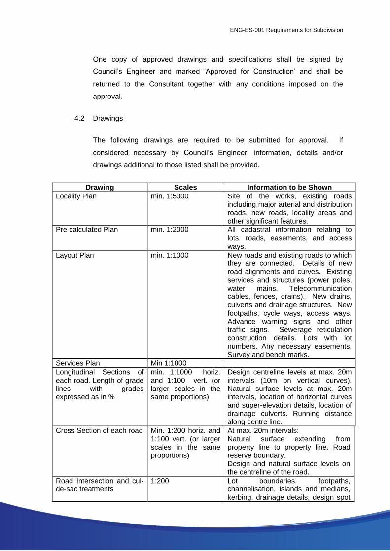
4.2 Drawings
The following drawings are required to be submitted for approval. If
considered necessary by Council’s Engineer, information, details and/or
drawings additional to those listed shall be provided.
Drawing Scales Information to be Shown
Locality Plan min. 1:5000 Site of the works, existing roads including major arterial and distribution roads, new roads, locality areas and other significant features.
Pre calculated Plan min. 1:2000 All cadastral information relating to lots, roads, easements, and access ways.
Layout Plan min. 1:1000 New roads and existing roads to which they are connected. Details of new road alignments and curves. Existing services and structures (power poles, water mains, Telecommunication cables, fences, drains). New drains, culverts and drainage structures. New footpaths, cycle ways, access ways. Advance warning signs and other traffic signs. Sewerage reticulation construction details. Lots with lot numbers. Any necessary easements. Survey and bench marks.
Services Plan Min 1:1000
Longitudinal Sections of each road. Length of grade lines with grades expressed as in %
min. 1:1000 horiz. and 1:100 vert. (or larger scales in the same proportions)
Design centreline levels at max. 20m intervals (10m on vertical curves). Natural surface levels at max. 20m intervals, location of horizontal curves and super-elevation details, location of drainage culverts. Running distance along centre line.
Cross Section of each road Min. 1:200 horiz. and 1:100 vert. (or larger scales in the same proportions)
At max. 20m intervals: Natural surface extending from property line to property line. Road reserve boundary. Design and natural surface levels on the centreline of the road.
Road Intersection and cul-de-sac treatments
1:200 Lot boundaries, footpaths, channelisation, islands and medians, kerbing, drainage details, design spot
ENG-ES-001 Requirements for Subdivision
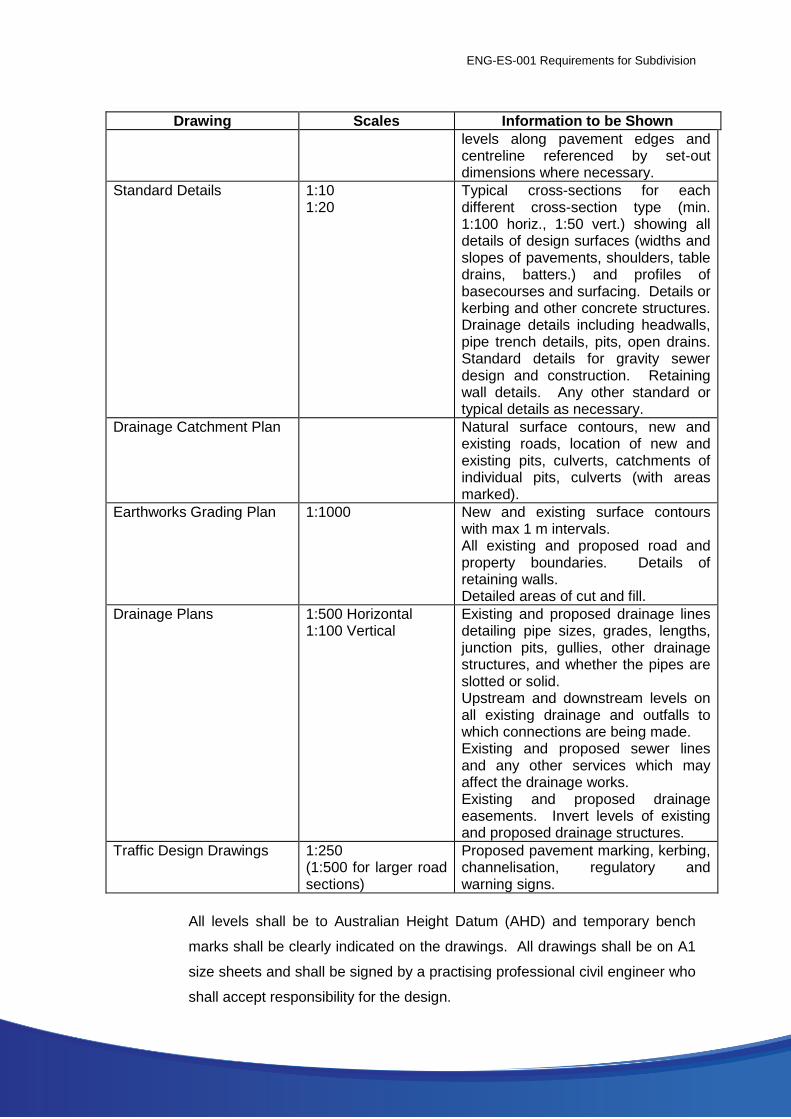
Drawing Scales Information to be Shown
levels along pavement edges and centreline referenced by set-out dimensions where necessary.
Standard Details 1:10 1:20
Typical cross-sections for each different cross-section type (min. 1:100 horiz., 1:50 vert.) showing all details of design surfaces (widths and slopes of pavements, shoulders, table drains, batters.) and profiles of basecourses and surfacing. Details or kerbing and other concrete structures. Drainage details including headwalls, pipe trench details, pits, open drains. Standard details for gravity sewer design and construction. Retaining wall details. Any other standard or typical details as necessary.
Drainage Catchment Plan Natural surface contours, new and existing roads, location of new and existing pits, culverts, catchments of individual pits, culverts (with areas marked).
Earthworks Grading Plan 1:1000 New and existing surface contours with max 1 m intervals. All existing and proposed road and property boundaries. Details of retaining walls. Detailed areas of cut and fill.
Drainage Plans 1:500 Horizontal 1:100 Vertical
Existing and proposed drainage lines detailing pipe sizes, grades, lengths, junction pits, gullies, other drainage structures, and whether the pipes are slotted or solid. Upstream and downstream levels on all existing drainage and outfalls to which connections are being made. Existing and proposed sewer lines and any other services which may affect the drainage works. Existing and proposed drainage easements. Invert levels of existing and proposed drainage structures.
Traffic Design Drawings 1:250 (1:500 for larger road sections)
Proposed pavement marking, kerbing, channelisation, regulatory and warning signs.
All levels shall be to Australian Height Datum (AHD) and temporary bench
marks shall be clearly indicated on the drawings. All drawings shall be on A1
size sheets and shall be signed by a practising professional civil engineer who
shall accept responsibility for the design.
ENG-ES-001 Requirements for Subdivision
4.3 Drainage Calculations
Submit drainage calculations for approval for every underground drain and all
open drains (except table drains) including but not necessarily limited to
bridges, pipe drains, box culvert drains. Calculations shall show catchment
areas, run-off coefficients, recurrence intervals, rainfall intensities, times of
concentration and method of sizing of drains. Calculations shall be set out in
a standard tabular format or approved format to facilitate checking.
4.4 Pavement Calculations
Submit pavement calculations for approval. Calculations shall show the
method adopted for calculation of subgrade CBR including test results, design
pavement life, design traffic loadings, determination of basecourse
thicknesses and need for subgrade stabilisation/improvement where
necessary. Provide copies of all subgrade tests.
4.5 Construction Drawing
The Developer shall provide the City’s Engineer with a full set of drawings
issued ‘For Construction’ or their latest revision in both electronic and hard
copy format prior to construction of the subdivision.
4.6 As-Constructed Drawings
The developer shall provide the City’s Engineer with a full set of ‘As
Constructed’ engineering drawings in both electronic (dxf or dwg) and hard
copy format prior to the release of the subdivision.
These drawings shall be in a reproducible form, clearly marked “As
constructed” and certified by a licensed surveyor as follows:
Road drawings to show details of any alterations made during
construction;
Drainage and sewer drawings and grades against the design lines,
levels and grades.
ENG-ES-001 Requirements for Subdivision
5. Control and Supervision of Construction
5.1 General
All subdivision works shall be designed and constructed in accordance with
sound engineering principles and in compliance with the approved drawings
and specifications.
Final approval for the works shall only be given when the whole of the works
shown on the drawings of subdivision have been executed to the true intent
and meaning of the approved drawings and specifications and to the
satisfaction of Council’s Engineer.
Traffic Management Plans, for the area affected by subdivisional works,
should be submitted to the City of Kalgoorlie Boulder for approval.
5.2 Responsibility for Quality of Construction
Irrespective of any approvals given by Council’s Engineer, the subdivider and
his responsible agents (including where applicable the Consulting Engineer
and/or the Contractor) shall remain fully responsible for the quality of the
works. The inspections, checks and tests to be carried out by Council’s
Engineer are not intended to be comprehensive or detailed and do not take
the place of comprehensive superintendence of the works by the Subdivider’s
Consulting Engineer.
All subdivision works shall be subject to the provisions of AS2990 ‘Quality
Systems for Engineering and Construction Projects’ and AS3900 to 3904
‘Quality Systems’. The quality assurance category to be adopted should be
Category C generally with only critical aspects to be subject to Category B
requirements. The Consultant shall ensure that all contract work complies
with these provisions.
5.3 Schedule of Inspections
Inspections by Council’s Engineer or his representative shall be required at
the following stages of construction of roads and drainage facilities. A
ENG-ES-001 Requirements for Subdivision
minimum of 48 hours notice shall be given by the Subdivider’s Consultant that
inspections are required:
(a) On completion of foundation and subgrade preparation and prior to
placing any fill and basecourses;
(b) After laying of drainage pipe (and culverts) and prior to backfilling
trenches;
(c) On completion of each of the basecourses and in particular immediately
prior to surfacing of basecourses;
(d) During application of bituminous surfacing;
(e) During laying of concrete kerbing;
(f) On practical completion of all of the subdivision works including survey
lot pegging and stabilisation.
No second or follow up stage of construction shall proceed until approval has
been given for the preceding stage.
Representatives of the Consultant and the Contractor shall be present at
stage inspections if requested by Council’s Engineer.
5.4 Testing and As Constructed Surveys
5.4.1 General
All test results and as constructed surveys taken during the works,
whether required under this part or not, shall be made available to
Council’s Engineer. All materials and compaction tests shall be carried
out by a NATA approved testing laboratory. All as constructed surveys
shall be carried out by an independent licensed surveyor. Works which
fail to meet specified criteria shall be corrected and re-tested or re-
surveyed, as the case may be, at Contractor’s/Developers cost.
5.4.2 Roadworks and Drainage

ENG-ES-001 Requirements for Subdivision
The following minimum tests shall be required:
(a) Grading and testing of properties of representative samples of
sub-base and basecourse materials prior to commencement of
supply of those materials;
(b) In situ density testing -
Embankment filling: 4 tests per 1000 cub.m
Sub-base and basecourse: 4 tests per 500 cub.m
Additional density tests of foundation and subgrade to road pavements
shall be taken at the Subdivider’s costs when requested by Council’s
Engineer.
The following minimum as constructed surveys shall be required by
Council:
(a) After completion of subgrade preparation and prior to cartage of
basecourses, take levels at no greater than 20m intervals on the
centreline and on both edges of pavement boxing. The as
constructed information shall be presented in plan or tabular form
showing the chainage, the design subgrade levels for each point,
the as constructed levels and the difference between the two.
(b) After completion of basecourse construction and prior to surfacing
(sealing), take levels at no greater then 20m intervals on the
centreline (at chainages to match subgrade levels) and on both
edges of basecourse. The as constructed information shall be
presented in plan or tabular form showing the chainage, the
design basecourse levels for each point, the as constructed levels
and the difference between the two.
(c) Pipe Drain systems and open drains (not including table drains).
Details shall include location and size of pipes and drains, length
between ends (or centreline distances to pits etc), lid or cover
levels where appropriate, and invert levels at ends. For open
ENG-ES-001 Requirements for Subdivision
drains bottoms widths, invert levels at no greater than 20m
intervals and side slopes shall additionally be required.
5.5 Sewers
Sewers and connection point shall be tested for watertightness with two
separate tests. The first shall be made after laying prior to backfilling the
trenches. The second test shall be made after backfilling of trenches is
completed.
The method of test shall be an air test as follows:-
UPVC pipe sewers and connecting points shall be plugged and subjected to
an air pressure of 50 kPa for three minutes. The air supply shall then be shut
off and the air pressure shall not fall below 35 kPa in less than one minute.
The following minimum as constructed information and surveys, prepared and
certified by a licensed surveyor, shall be required by Council plotted on base
maps to match Council’s sewer plan index system at a minimum scale of
1:500.
(a) the location of the centreline of every manhole referenced to lot boundaries;
(b) distance from centreline to centreline between every manhole and the distance from the centreline of a manhole to the plugged end of every inspection opening;
(c) all pipe invert levels at the internal face of manholes;
(d) reduced level of tops or covers of manholes;
(e) surface level and invert level at all inspection openings;
(f) identification number of manholes;
(g) type of access chamber, e.g. drop;
(h) pipe diameter of all sewer lines between manholes, and manholes and inspection openings;
(i) distance along the centreline of the sewer from the centre of the downstream manhole to the plugged end of every branch to boundary connections. All branches brought up and/or into lot boundaries shall be detailed;
(j) distance from centreline of downstream manhole to centreline of slop junctions;
ENG-ES-001 Requirements for Subdivision
(k) distance from centreline of downstream manhole of start and stop of concrete encasement, including details of pipe sleeves and cement grouting for railway crossings;
(l) type of:
(i) pipe jointing (e.g. solvent weld),
(ii) bedding to sewer (e.g. crushed metal),
(iii) backfill.
5.6 Practical Completion
Any items of work found to require rectification at the time of the practical
completion inspection, shall be rectified before certification of practical
completion is issued.
The Consultant shall notify Council’s Engineer in writing of the practical
completion date following satisfactory completion of all subdivisional works.
If at anytime after the granting of practical completion the subdivisional work is
found to be contrary to Council’s requirements, or is found to have been
constructed in error to the approved drawings, specifications and any
instructions which may have been issued by the Consultant or Council’s
Engineer during the course of construction, then the works shall be rectified at
no cost to the Council. Minor rectification items may be undertaken at the
completion of the defects liability period.
6. Maintenance and Release
6.1 Survey Release
The Subdivider or his nominated representative shall satisfy Council that the
Subdivider has complied with all relevant conditions imposed by the Western
Australian Planning Commission pertaining to survey release of all or part of a
constructed subdivision.
The conditions which must be complied with by the Subdivider prior to the
Council’s approval of survey release of a subdivision shall include, but shall
not necessarily be limited to, the following:
(a) Creation and location of all stormwater drainage easements;
ENG-ES-001 Requirements for Subdivision
(b) Creation of any other easements (temporary or permanent) which are
relevant to the subdivision;
(c) Creation of all reserves (including drainage and recreation reserves)
pertaining to the subdivisional works;
(d) Payment of all monies required to be paid to the Council in
consideration of construction of footpaths, footways or any other works
associated with the subdivision and which are to be carried out by the
Council;
(e) Payment of any maintenance retention money (of lodgement of bank
guarantees) and payment of supervision fees required by Council;
(f) Stabilisation of topsoil sand or other material or matter subject to
movement over or near the subdivision shall be completed to the
satisfaction of Council’s Engineer;
(g) Completion of all roadworks and other works associated with the
subdivisional construction to the stage of practical completion;
(h) Lodgement of all as constructed drawings required by Council. One set
of hard copies and a set of drawings on disk in AutoCAD/CivilCAD
format.
6.2 Supervision Fees
Supervision fees calculated in accordance with section 295 (6) (b) of the Local
Government Act (Ref Cl 2.6 b) shall be paid by the Subdivider to the Council
before construction commences. The amount of the payment shall be based
on the estimated cost of all of the works at the time. Upon certification of
practical completion of the works, the consultant shall provide the actual
construction cost of the works and the amount of the fee shall be adjusted
accordingly, if necessary.
ENG-ES-001 Requirements for Subdivision
6.3 Sewerage Headworks Contribution
A sewerage headworks contribution shall be paid by the Subdivider to the
Council before construction commences.
Sewerage headworks charges shall be applied to all subdivisional
developments, (Residential/Commercial, Industrial/Other), except as
determined by Council and notified in writing, with such sewerage headworks
charges to be as established in any current WCWA document “Headworks
Contributions” and increased/decreased in accordance with the current (of any
particular year of time) WCWA standards.
6.4 Maintenance
A twelve months defects liability period shall apply from the date of practical
completion of the subdivisional works. During this period the Subdivider
and/or his responsible agents shall be responsible for rectification of any
defects, whether they are construction or design defects, which may become
apparent. The Subdivider or his responsible agents shall carry out
rectification work within the time requested by Council when notified of such
defects. If defects are not rectified within the time required by Council then
Council may have the defects rectified at the Subdivider’s expense. In this
case the cost of the work shall become a debt due to the Council and Council
may draw on any retention money or bank guarantee being held, without
reference to or approval from the Subdivider and without limiting its right to
recover any balance of money due should the security be insufficient to cover
the costs of the work.
Before practical completion is granted the Subdivider shall lodge with the
Council an amount of 5% of the costs of the works as security for ensuring the
rectification of defects, which shall be retained by Council for the duration of
the defects liability period. Alternatively a bank guarantee of approved form
may be lodged in lieu of retention money.
The bank guarantee shall contain clauses wherein the bank shall guarantee to
pay to Council unconditionally on demand any amount up to the total amount
of the guarantee at any time so required, and that the guarantee shall not be
ENG-ES-001 Requirements for Subdivision
withdrawn until notified by Council (i.e. it shall not have a termination date).
Any bank guarantee lodged with the Subdivider by a Contractor in lieu of
retention money shall be acceptable as part or full security (as the case may
be) provided it is in a form which is acceptable to Council.
Any defect rectified during the defects liability period shall be subject to a
further twelve months defects liability period. During this further period
Council may, at its discretion, withhold the release of all or part of any
security.
Retention money or bank guarantees shall only be released at the expiration
of the defects liability period (or any further period) after satisfactory
rectification of all defects.
6.5 Landscape Maintenance Bond
All landscaping and grassing shall be supported by a maintenance and
watering period of at least two summer periods to ensure full establishment.
This condition shall be guaranteed by way of a maintenance bond in the form
of cash or a guarantee from a financial institution acceptable to Council. The
bond will be returned when the maintenance period has been satisfactorily
completed.
Relevant Documents