polishing of assab mould steel
TRANSCRIPT

POLISHING OF ASSAB MOULD STEEL
2 | POLISHING OF MOULD STEEL
CONTENTS
Why strive for a high surface finish 2
Factors that affect the surface finish 2
Surface preparation of tool steel 4
Guidelines 5
Polishing problems can be solved 8
Measuring surface roughness and quality 9
Why strive for a high surface finish?Plastic and metallic components are manufactured with various surface finishes all from shiny and glossy to functional surfaces of different appearances. In this brochure we will inform about the factors that have the biggest impact on the polishability of tool steel and give recommendations on how to obtain the required surface finish on moulds, dies, punches and metallic components/parts.
Depending on the application and requirements we can distinguish between two types of surface finishing methods:high gloss polishing and functional polishing.
HIGH GLOSS POLISHING
Tools for plastic moulding do require a high surface finish especially when extreme transparency and/or high gloss are aimed for. In such cases it is of utmost importance to choose a proper tool material and establish a suitable surface preparation technique. To achieve a reflective surface with mirror finish the preparation process must involve several grinding and diamond polishing steps and these have to
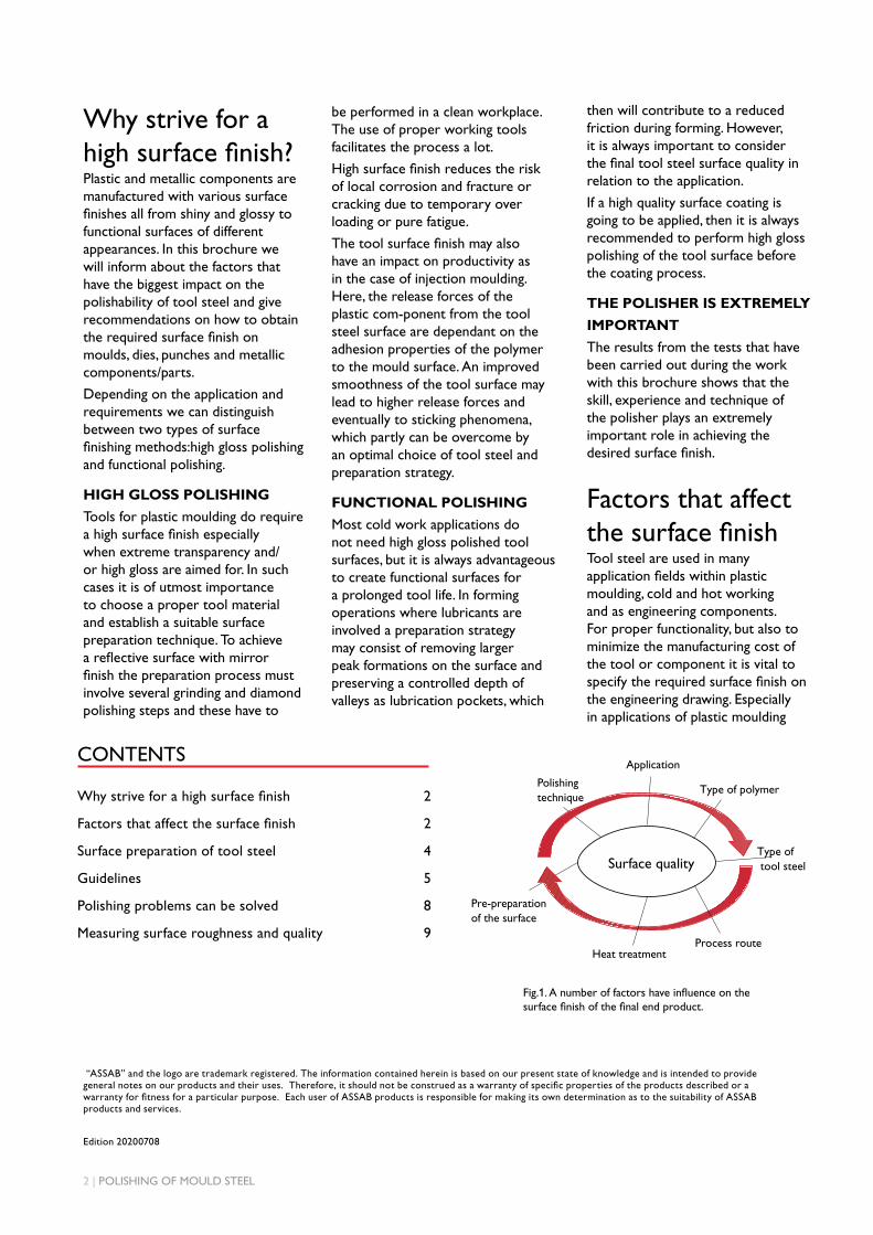
Factors that affect the surface finishTool steel are used in many application fields within plastic moulding, cold and hot working and as engineering components. For proper functionality, but also to minimize the manufacturing cost of the tool or component it is vital to specify the required surface finish on the engineering drawing. Especially in applications of plastic moulding
Fig.1. A number of factors have influence on the surface finish of the final end product.
Polishing technique
Application
Type of polymer
Type of tool steel
Pre-preparation of the surface
Heat treatmentProcess route
Surface quality
be performed in a clean workplace. The use of proper working tools facilitates the process a lot.
High surface finish reduces the risk of local corrosion and fracture or cracking due to temporary over loading or pure fatigue.
The tool surface finish may also have an impact on productivity as in the case of injection moulding. Here, the release forces of the plastic com-ponent from the tool steel surface are dependant on the adhesion properties of the polymer to the mould surface. An improved smoothness of the tool surface may lead to higher release forces and eventually to sticking phenomena, which partly can be overcome by an optimal choice of tool steel and preparation strategy.
FUNCTIONAL POLISHING
Most cold work applications do not need high gloss polished tool surfaces, but it is always advantageous to create functional surfaces for a prolonged tool life. In forming operations where lubricants are involved a preparation strategy may consist of removing larger peak formations on the surface and preserving a controlled depth of valleys as lubrication pockets, which
then will contribute to a reduced friction during forming. However, it is always important to consider the final tool steel surface quality in relation to the application.
If a high quality surface coating is going to be applied, then it is always recommended to perform high gloss polishing of the tool surface before the coating process.
THE POLISHER IS EXTREMELY
IMPORTANT
The results from the tests that have been carried out during the work with this brochure shows that the skill, experience and technique of the polisher plays an extremely important role in achieving the desired surface finish.
“ASSAB” and the logo are trademark registered. The information contained herein is based on our present state of knowledge and is intended to provide general notes on our products and their uses. Therefore, it should not be construed as a warranty of specific properties of the products described or a warranty for fitness for a particular purpose. Each user of ASSAB products is responsible for making its own determination as to the suitability of ASSAB products and services.
Edition 20200708
POLISHING OF MOULD STEEL | 3
Defects in tool steel
Various types of defects emanating from the production process may be found in the steel. During steelmaking non-metallic inclusions are formed as a result of the deoxidation process. Other sources are entrapped exo-genous material from refractory in the ladle or at casting. A fast solidification rate is normally beneficial by giving less time for inclusions and particles to grow and reducing segregation patterns.
In the special remelting processes such as VAR and ESR the cast ingot are remelted under controlled conditions. Non-metallic oxide inclusions are effectively removed from the steel and sulphides are reduced substantially via the basic working slag in the ESR-process
TOOL STEEL QUALITY
Process routes for tool steel
Tool steel are found in various alloy combinations to fit usage in different application fields. Common manufacturing process routes are conventional ingot casting (IC), continuous casting (CC), electro slag remelting (ESR), vacuum arc remelting (VAR) and powder metallurgy (PM). Remelting processes and PM processes produce materials of higher homogeneity with a low non-metallic inclusion content,
Recommendations
To produce highly reflective and glossy surfaces ESR-remelted or PM steel are to be used. However, conventional ingot cast steel can give a very good surface finish, if both steel manufacturing and polishing are performed according to a good practice.
Fig 3. Process routes for tool steel and example of steel grades produced by the different routes.
CONVENTIONAL PROCESSASSAB STEEL GRADES:CALMAXASSAB XW-10ASSAB 718 SUPREMENIMAXRAMAX HHASSAB 8407 2MCORRAX
ELECTROSLAG REMELTING PROCESSASSAB STEEL GRADES:STAVAX ESRMIRRAX ESRMIRRAX 40ASSAB 8407 SUPREMEVIDAR 1 ESRUNIMAXDIEVAR
POWDER METALLURGY PROCESSASSAB STEEL GRADES:VANADIS 4 EXTRA SUPERCLEANVANADIS 10 SUPERCLEANELMAX SUPERCLEAN
whereas ingot cast materials normally have a higher degree of segregation patterns and also contain more non-metallic inclusions.
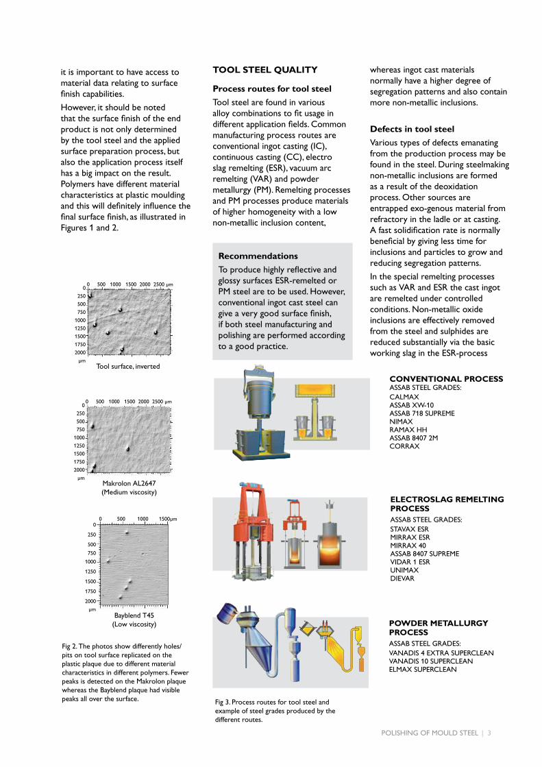
Fig 2. The photos show differently holes/pits on tool surface replicated on the plastic plaque due to different material characteristics in different polymers. Fewer peaks is detected on the Makrolon plaque whereas the Bayblend plaque had visible peaks all over the surface.
0
250
500
750
1000
1250
1500
1750
2000
µm
0 500 1000 1500µm
Bayblend T45(Low viscosity)
0 500 1000 1500 2000 2500 µm
Makrolon AL2647(Medium viscosity)
0
250
500
750
1000
1250
1500
1750
2000
µm
0 500 1000 1500 2000 2500 µm
Tool surface, inverted
0
250
500
750
1000
1250
1500
1750
2000
µm
it is important to have access to material data relating to surface finish capabilities.
However, it should be noted that the surface finish of the end product is not only determined by the tool steel and the applied surface preparation process, but also the application process itself has a big impact on the result. Polymers have different material characteristics at plastic moulding and this will definitely influence the final surface finish, as illustrated in Figures 1 and 2.

4 | POLISHING OF MOULD STEEL
Polishing
The abrasives are more or less fixed in the carrier material and will cut and/or plough the surface.
Buffing
The abrasive adhere loosely to a flexible carrier (soft disk made of cloth or hide). This step is considered among some polisher to be the last polishing step performed in order to obtain a mirror like surface.
Surface preparation of tool steelThe following four terms are commonly used when it comes to surface preparation of tool steel. The essential characteristics of these methods are explained below.
Grinding
The abrasive particles are firmly bonded to a carrier such as grinding paper, stones and the discs.
Lapping
The abrasive particles are not bonded but move freely between the carrier and the work piece.
A
BSample
GlueBacking
Total number of particles per mm2 * (oxides + sulphides + carbides + nitrides) 1000
100
10
1
0.1
altogether giving tool steel of high cleanliness.
The remelting processes direct the casting structure in such a way that macro segregations are drastically reduced and a more uniform microstructure is created, which is beneficial from polishing point of view.
PM ESR
Fig. 4. A low defect content is beneficial from polishing point of view.
Conventional
INGOT CAST STEEL
Polishability rank 5
4
3
2
1
Bad
Good
Low High
Defect content by inclusions and carbides
ESR REMELTED STEELPM
*oxides and sulphides >3µm carbides and nitrides >4µm
Heat treatment
Heat treatment can affect polishability in many ways. Decarburisation or recar burisation of the surface during heat treatment can produce variations in hardness, resulting in polishing difficulties.
In order to avoid this it is recommended that the hardening is carried out in vacuum furnaces or furnaces with controlled protective gas atmosphere or salt baths. It is also of importance to secure that the time at austenitizing temperature is not too long and the quenching speed is not too slow to avoid grain growth and grain boundary precipitations.
HINTS FOR GRINDING
Table 1. Typical initial surface roughness values Ra and Rz.
Recommendations
To facilitate the finishing steps and to minimize the risk of losing dimensional tolerances of the tool the initial surface finish should have a roughness value of maximum Ra / Rz = 0.5/5 µm. This will eliminate the need of using coarse grinding media in the first preparation step.
MANUFACTURING OF
INITIAL SURFACES
It should be emphasised that the grinding operation forms the basis for a rapid and successful polishing job. In grinding, the marks left by the rough-machining operation are eliminated and a metallically pure and geometrically correct surface is obtained.
The finishing preparation steps can be very time consuming and costly, but can be controlled to a certain extent by a proper manufacturing of the initial tool surface. Normally the starting surface is ground, milled or electro discharge machined (EDM). Typical initial surface roughness values, as Ra/Rz, are approximately 0.5/5 µm for the two former and 3/15 µm for an EDM surface.
Recent developments in high speed machining has made it possible to produce surface finishes better than Ra = 0.2 µm and by using the latest tech-niques in EDM the Ra falls below 0.07 µm. After EDM processing it is important to remove the heat affec-ted layers by either a fine sparking and/or by grinding. If not doing so crack initiation may appear during tool use.
Sample
A
B
Suspension
Support
A
B
Sample
OPERATION SURFACE FINISH
Ground Ra 0.5 µm Rz 5 µm
Milled Ra 0.5 µm Rz 5 µmHigh speed machined
Ra 0.2 µm Rz 1.5 µm
EDM Ra 3.0 µm Rz 15 µm
POLISHING OF MOULD STEEL | 5
Recommendations
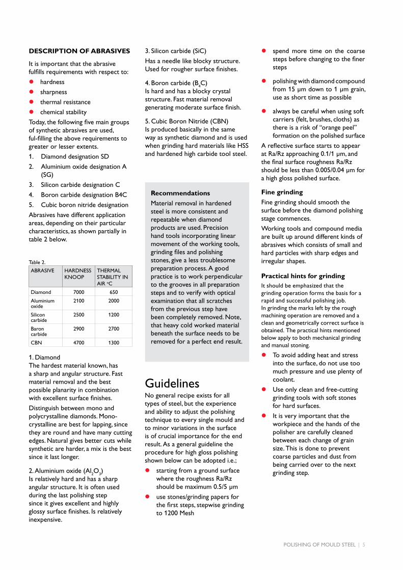
Material removal in hardened steel is more consistent and repeatable when diamond products are used. Precision hand tools incorporating linear movement of the working tools, grinding files and polishing stones, give a less troublesome preparation process. A good practice is to work perpendicular to the grooves in all preparation steps and to verify with optical examination that all scratches from the previous step have been completely removed. Note, that heavy cold worked material beneath the surface needs to be removed for a perfect end result.
3. Silicon carbide (SiC)
Has a needle like blocky structure. Used for rougher surface finishes.
4. Boron carbide (B4C)
Is hard and has a blocky crystal structure. Fast material removal generating moderate surface finish.
5. Cubic Boron Nitride (CBN) Is produced basically in the same way as synthetic diamond and is used when grinding hard materials like HSS and hardened high carbide tool steel.
Practical hints for grindingIt should be emphasized that the grinding operation forms the basis for a rapid and successful polishing job. In grinding the marks left by the rough machining operation are removed and a clean and geometrically correct surface is obtained. The practical hints mentioned below apply to both mechanical grinding and manual stoning.
z To avoid adding heat and stress into the surface, do not use too much pressure and use plenty of coolant.
z Use only clean and free-cutting grinding tools with soft stones for hard surfaces.
z It is very important that the workpiece and the hands of the polisher are carefully cleaned between each change of grain size. This is done to prevent coarse particles and dust from being carried over to the next grinding step.
GuidelinesNo general recipe exists for all types of steel, but the experience and ability to adjust the polishing technique to every single mould and to minor variations in the surface is of crucial importance for the end result. As a general guideline the procedure for high gloss polishing shown below can be adopted i.e.;
z starting from a ground surface where the roughness Ra/Rz should be maximum 0.5/5 µm
z use stones/grinding papers for the first steps, stepwise grinding to 1200 Mesh
DESCRIPTION OF ABRASIVES
It is important that the abrasive fulfills requirements with respect to:
z hardness
z sharpness
z thermal resistance
z chemical stability
Today, the following five main groups of synthetic abrasives are used, ful-filling the above requirements to greater or lesser extents.
1. Diamond designation SD
2. Aluminium oxide designation A (SG)
3. Silicon carbide designation C
4. Boron carbide designation B4C
5. Cubic boron nitride designation
Abrasives have different application areas, depending on their particular characteristics, as shown partially in table 2 below.
1. Diamond The hardest material known, has a sharp and angular structure. Fast material removal and the best possible planarity in combination with excellent surface finishes.
Distinguish between mono and polycrystalline diamonds. Mono-crystalline are best for lapping, since they are round and have many cutting edges. Natural gives better cuts while synthetic are harder, a mix is the best since it last longer.
2. Aluminium oxide (Al2O
3)
Is relatively hard and has a sharp angular structure. It is often used during the last polishing step since it gives excellent and highly glossy surface finishes. Is relatively inexpensive.
z spend more time on the coarse steps before changing to the finer steps
z polishing with diamond compound from 15 µm down to 1 µm grain, use as short time as possible
z always be careful when using soft carriers (felt, brushes, cloths) as there is a risk of “orange peel” formation on the polished surface
A reflective surface starts to appear at Ra/Rz approaching 0.1/1 µm, and the final surface roughness Ra/Rz should be less than 0.005/0.04 µm for a high gloss polished surface.
Fine grinding
Fine grinding should smooth the surface before the diamond polishing stage commences.
Working tools and compound media are built up around different kinds of abrasives which consists of small and hard particles with sharp edges and irregular shapes.
ABRASIVE HARDNESS KNOOP
THERMAL STABILITY IN AIR oC
Diamond 7000 650
Aluminium oxide
2100 2000
Silicon carbide
2500 1200
Baron carbide
2900 2700
CBN 4700 1300
Table 2.
6 | POLISHING OF MOULD STEEL
Standard
45°
90°
Irregular overlapping
Fig. 5. Grinding directions.
A
B
C
D
50
80
120
180
220
320
800
1200
45 µm
25
15
9631
Practical hints for polishing
Above all, cleanliness in every step of the polishing operation is of such importance that it cannot be overemphasized.
z Each polishing tool should be used for only one paste grade and kept in dust proof containers.
z Paste should be applied to the polishing tool in manual polishing, while in machine polishing the paste should be applied to the workpiece.
z Polishing pressure should be adjusted to the hardness of the polishing tool and the grade of paste. For the finest grain sizes, the pressure should only be the weight of the polishing tool.
z Work with hard carriers for as many steps as possible and work for as short a period as possible with soft carriers.
z Polishing should start in the cor- ners, edges and fillets but be careful with sharp corners and edges so they are not rounded off.
z Finish polishing step should, if possible, be carried out in
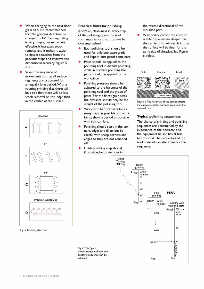
Figure 6. The hardness of the carrier affects the exposure of the diamond grains and the removal rate.
Typical polishing sequences
The choice of grinding and polishing sequences are determined by the experience of the operator and the equipment he/she has at his/her disposal. The properties of the tool material can also influence the sequence.
Fig. 7. This figure shows example of how the polishing sequence can be selected.
Soft Medium Hard
Felt Wood Steel
Hardened steel
Rough Grain number
Rough
Rough Micron size
Grain number
FEPA
Rough grinding
MillingTurningEDM’ing
Fine Fine
Fine Polishing withdiamond paste
the release directional of the moulded part.
z With softer carrier the abrasive is able to penetrate deeper into the carrier. This will result in that the surface will be finer for the same size of abrasive. See Figure 6 below.
z When changing to the next finer grain size, it is recommended that the grinding direction be changed to 45°. Cross-grinding is very simple, but extremely effective. It increases stock removal and it makes it easier to detect scratches from the previous steps and improve the dimensional accuracy. Figure 5 A–C.
z Select the sequence of movements so that all surface segments are processed for an equally long period. With a rotating grinding disc there will be a risk that there will be less stock removal on the edge than in the centre of the surface.
Fine grinding
50
80
120
180
220
320
800
1200
45 µm
25
15
9631

POLISHING OF MOULD STEEL | 7
Example of different polishing
strategies at high gloss polishing
All polishers have their own procedures for high gloss polishing. The data, in Tables 3–5, reflects that different manual polishing strategies
Table 4.
Table 3.
Table 5.
can be adopted to reach the same final surface finish by using rigorous and well proven working procedures. The achieved surface finish is lower than Ra 0.01 µm
The tables 3 and 4 show examples of specific step-by-step information regarding high gloss polishing of Stavax ESR and Unimax.
Observe carefully, during the polishing steps, if any deep marks are visible in the polished surface. If this problem occur it is needed to immediately reduce the pressure, put on polishing oil or if more diamond paste needs to be added.
STEP TECHNIQUE TYPE OF TOOL LUBRICATION
1 Hand-held unit Stone 320 Dielectric oil
2 Hand-held unit Stone 400 Dielectric oil
3 Hand-held unit Stone 600 Dielectric oil
4 Hand-held unit Paper 400 Dry
5 Hand-held unit Paper 600 Dry
6 Hand-held unit Paper 800 Dielectric oil
7 Hand-held unit (linear) Brass 5 x 5 mm DP 9 µm Dielectric oil
8 Hand-held unit (linear) Wood 5 x 5 mm DP 9 µm Dielectric oil
9 Hand-held unit (linear) Wood 5 x 5 mm DP 6 µm Polishing oil
10 Hand-held unit (rotational) Hard felt 10 mm DP 3 µm Polishing oil
11 Hand-held unit Piece of cotton wool DP 1 µm Polishing oil
STEP TECHNIQUE TYPE OF TOOL LUBRICATION
1 Ground
2 Hand-held unit SIC paper K320 Dry
3 Hand-held unit Hand-held unit K800 Dry
4 Hand-held unit Hand-held unit K1500 Dry
5 Hand-held unit Acryl Dfluid 6 µm Polishing oil
6 Hand-held unit Acryl Dfluid 3 µm Polishing oil
7 HaHand-held unit /Cotton Dfluid 3 µm Polishing oil
STEP TECHNIQUE TYPE OF TOOL LUBRICATION
1 Reciprocating machine 9500 Rpm Amplitude movment 0.2 mm
Brass carrierPlastic carrier
DP W 15 µm Polishing oil
2 Hand-held unit SIC paper DP W 10 µm Polishing oil
3 Hand-held unit Hand-held unit DP W 5 µm Polishing oil
4 Hand-held unit Hand-held unit DP W 3 µm Polishing oil
5 Hand-held unit Acryl Dfluid 6 µm Polishing oil

8 | POLISHING OF MOULD STEEL
Polishing problems can be solvedThe predominant problem in polishing is so-called “overpolishing”. This terminology is used when a polished surface gets worse the longer you polish it. There are basically two phenomena which can appear when a surface is overpolished: “orange peel” and “pitting” (pin holes). These problems often occur when changing from hard to a soft tool (felt/brush).
A material at higher hardness can better withstand a high polishing pressure compared with prehardened steel. Subsequently material with low hardness will become “over-polished” more easily.
ORANGE PEEL
The appearance of an irregular, rough surface, which is normally referred to as “orange peel”, might depend on different causes. The most common is polishing with high pressure and prolonged time during the last polishing steps. A material at high hardness is less sensitive to problems with “orange peel” compared to prehardened or soft annealed material.
z If a polished surface shows signs of an appearance like “orange peel”; stop polishing! There is no idea to increase the polishing pressure and continue to polish. Such a course of action will only result in a worse set of problems.
z Following steps are recommended to restore the surface. Remove the defective surface layer by regrinding it, by using the last grinding step prior to polishing. Use a lower pressure and shorter time during the polishing steps than what was used when the problems occurred.
PITTING
The very small pits (pin holes) which can occur in a polished surface generally result from non-metallic inclusions or hard carbides which have been torn out from the surface during the polishing process. Pitting can also be caused by hard particles embedded in a softer matrix. During polishing the matrix will be removed at a more rapid rate than the hard particles. Polishing will gradually “undermine” the hard particles until they are torn out of the material by further polishing. The problem is most often encountered when polishing with diamond paste grain size less than 10 µm and soft polishing tools (felt, brush).
If pitting occurs the following measures should be taken:
z regrind the surface carefully using the last grinding step prior to polishing
z use a hard coarse tool and repeat the polishing process
When using grain size 10 µm and smaller:
z the softest polishing tools should be avoided
z the polishing process should be carried out for the shortest possible time and under the lowest possible pressure
0.5 mm
“Orange peel”
0.5 mm
“Pitting”

POLISHING OF MOULD STEEL | 9
0 100 200 300 400 500 600 µm0
50
100
150
200
250
300
350
400
450
µm
Measuring surface roughness and qualityPolished mould surfaces are traditionally estimated by the naked eye and/or measured by mechanical profilers for surface roughness, commonly described with the Ra, Rz and Rt values.
Table 6. Approximate comparison between requested surface roughness measured by mechanical profilers and international standards.
SURFACE ASSESSMENT BY
ROUGHNESS PARAMETERS
The benefit to measure surfaces is both the possibility to study them in the micro- and nano-scale, and a way to quantitatively evaluate them. But, there is a huge amount of available 2D- and 3D parameters (abbreviated R- and S-parameters, respectively), so how do you know which to use?
2D parameters, usually obtained by a mechanical profiler, can be used to quantify the surface quality in a limited extent. The most frequent used in practical work with moulds is the Ra-value describing the average height of the measured surface. However, it is a rather poor description of the mould surface since smaller defects and certain textures will be “averaged out” and/or undetected. See figure 8.
Ra – the arithmetical mean deviation of the profile is the mean value of the absolute value of the profile departure y within the reference length l.Source: The figure to the left is from T.R. Thomas book “Rough surfaces” 2nd edition.
The A- & B-profiles illustrate one of the major disadvantages of the 2D profilometry; A – a surface with pores, and B – a “defect free” surface, i.e. the results are strongly dependent on the profile location.
Illustration of different surface topographies with equal Ra-value; i.e. the Ra-value itself is not enough to fully describe the surface structureSource: Illustration from T.R. Thomas book “Rough surfaces” 2nd edition.
Fig. 8.
Ra= 2.4 µm
Ra= 2.5 µm
Ra= 2.4 µm
However, these methods are both subjective and uncertain compared to more advanced surface- and sub-surface measurement devices capable of measuring to fractions of nano-metres. The use of 3D-instrumentation with higher resolution provides more accurate surface measurements of moulds with complex geometries which in turn means that quantitative surface quality controls can be performed.
SURFACE ROUGHNESS ACC.TO DIN/ISO 1302 SURFACE ROUGHNESS ACC. TO SPI
ROUGHNESSRa, µm
ROUGHNESSRmax, µm
ACHIEVED AFTER GRINDING/POLISHING WITH
N 1 0.025 0.1-0.3 A-1 3 µm Diamond PasteN 2 0.05 0.3-0.7 A-2 6 µm Diamond PasteN 3 0.1 0.75-1.25 A-3 15 µm Diamond PasteN 4 0.2 1.5-2.5 B-1 600 Grit PaperN 5 0.4 2-6 B-2 400 Grit PaperN 6 0.8 6-10 B-3 320 Grit PaperN 7 1.6 10-20 C-1 600 Grit StoneN 8 3.2 20-40 C-2 400 Grit StoneN 9 6.3 ~60 C-3 320 Grit StoneN 10 12.5 ~125 D-1 600 Stone Prior to Dry Blast Glass Beads #11N 11 25 ~250 D-2 400 Stone Prior to Dry Blast #240 Alminium oxideN 12 50 ~500 D-3 320 Stone Prior to Dry Blast #240 Aluminium oxide
10 | POLISHING OF MOULD STEEL
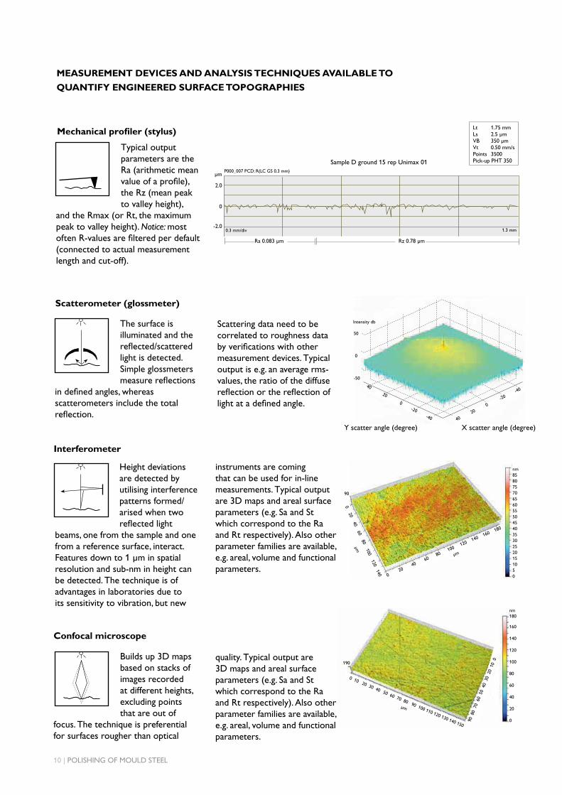
Typical output parameters are the Ra (arithmetic mean value of a profile), the Rz (mean peak to valley height),
and the Rmax (or Rt, the maximum peak to valley height). Notice: most often R-values are filtered per default (connected to actual measurement length and cut-off).
instruments are coming that can be used for in-line measurements. Typical output are 3D maps and areal surface parameters (e.g. Sa and St which correspond to the Ra and Rt respectively). Also other parameter families are available, e.g. areal, volume and functional parameters.
Builds up 3D maps based on stacks of images recorded at different heights, excluding points that are out of
focus. The technique is preferential for surfaces rougher than optical
Mechanical profiler (stylus)
The surface is illuminated and the reflected/scattered light is detected. Simple glossmeters measure reflections
in defined angles, whereas scatterometers include the total reflection.
Scatterometer (glossmeter)
Confocal microscope
nm8580757065605550454035302520151050
90
0 20 40 60 80 100 120 140
µm
Y scatter angle (degree) X scatter angle (degree)
40 20 0 -20 -40 40 2
0 0
-20 -4
0
MEASUREMENT DEVICES AND ANALYSIS TECHNIQUES AVAILABLE TO
QUANTIFY ENGINEERED SURFACE TOPOGRAPHIES
µm
2.0
0
-2.0
Ra 0.083 µm Rz 0.78 µm
0.3 mm/div 1.3 mm
P000_007 PCD: R(LC GS 0.3 mm)
Sample D ground 15 rep Unimax 01
Lt 1.75 mmLs 2.5 µmVB 350 µmVt 0.50 mm/sPoints 3500Pick-up PHT 350
190
nm180
160
140
120
100
80
60
40
20
0
90
80
70
60
50
40
30
20
10
0
0 10 20 30 40 50 60 70 80 90 100 110 120 130 140 150
µm
quality. Typical output are 3D maps and areal surface parameters (e.g. Sa and St which correspond to the Ra and Rt respectively). Also other parameter families are available, e.g. areal, volume and functional parameters.
50
0
-50
Scattering data need to be correlated to roughness data by verifications with other measurement devices. Typical output is e.g. an average rms-values, the ratio of the diffuse reflection or the reflection of light at a defined angle.
Intensity db
Interferometer
Height deviations are detected by utilising interference patterns formed/arised when two reflected light
beams, one from the sample and one from a reference surface, interact. Features down to 1 µm in spatial resolution and sub-nm in height can be detected. The technique is of advantages in laboratories due to its sensitivity to vibration, but new
0 20
40 60
80 100 1
20 140 1
60 180
µm

POLISHING OF MOULD STEEL | 11
SEM/EDS
A focused electron beam raster-scans the surface; the energetic electrons interact with the atoms in the sample
within a few nm to several µm of the surface, i.e. scattering events take place (primary electrons loose energy and/or change direction). The
emitted electrons are “collected” by different detectors. The EDS, a type of X-ray spectrometer, allows elemental analysis. Typical output are the topographical contrast (based on SE), chemical contrast (based on BSE) and phase composition (based on X-ray).
Atomic force microscope
Simply described as a tiny profiler/stylus operating with extremely small probe tips barely touching the surface
resulting in 3D resolutions close to atomic level. Typical output are 3D maps and areal surface parameters.
Selection of Measurement Devices and General Specifications
0 5 10 15 20 25 30 35 µm
µm
35
30
25
20
15
10
5
0
Table 7. The figures shown should only be considered as guidelines.
GENERAO SPEC/DEVICE
LIGHT OPTICAL MICROSCOPE
STYLUSINTERFERO-
METERCONFOCAL SEM/EDS
ATOMIC FORCE MICROSCOPE
GLOSSMETER
Resolution (m) xy: 10-7
z: 10-6xy: 10-6 – 10-4
z: 10-9xy: 10-6
z: 10-10xy: 10-4
z: 10-7xy: 10-9
z: 10-9xy: 10-10
z: 10-12 -
Measurement area µm-mm µm-cm µm µm-mm µm-mm µm µm-mm
Height info No No Yes Yes No Yes Possible
2D/3D 2D 2D 3D 3D 2D/3D 3D -
Component analysis No No No No Yes No
Usability Good Good Mid Mid Bad Bad Good
Measurement time - Long Short Mid Long Long Short
Size of workpiece Device dependent UnlimitedDevice dependent
(often up to 2-10 kg)
Device dependent (often up to
2-10 kg)mm-cm Device dependent Unlimited
Other
Standardised methods for cleanliness
dermination
Risk of surface damage, fragile stylus/pickup
Sensitive to vibrations
Large depth of focus, problems with artefacts
Work in vacuum, needs solid
and conducting samples, ability to image undercuts
Noise sensitive, fragile stylus/
pick-up
Only average roughness data
Choosing the right steel is of vital importance. ASSAB engineers and
metallurgists are always ready to assist you in your choice of the
optimum steel grade and the best treatment for each application.
ASSAB not only supplies steel products with superior quality, we offer
state-of-the-art machining, heat treatment and surface treatment
services to enhance steel properties to meet your requirement in the
shortest lead time. Using a holistic approach as a one-stop solution
provider, we are more than just another tool steel supplier.
ASSAB and Uddeholm are present on every continent. This ensures
you that high quality tool steel and local support are available wherever
you are. Together we secure our position as the world’s leading
supplier of tooling materials.
For more information, please visit
www.assab.com