pollutant formation and control
DESCRIPTION
About emissions and control descriptiveTRANSCRIPT

Pollutant Formation and Control

Pollutant Formation and Control
• All IC engines produce undesirable emissions as a result of combustion.
• The emissions of concern are unburned hydrocarbons (UHC), carbon monoxide (CO), oxides of nitrogen such as nitric oxide and nitrogen dioxide (NOx), sulfur dioxide, and solid carbon particulates.
• These emissions pollute the environment and contribute to acid rain, smogodors, and respiratory and other health problems.
• HC emissions from gasoline-powered vehicles include a number of toxic substances such as benzene, polycyclic aromatic hydrocarbons (PAHs), 1,3-butadiene and three aldehydes (formaldehyde, acetaldehyde, acrolein).
• Carbon dioxide is an emission that is not regulated but is the primary greenhouse gas responsible for global warming.

• During the 1940s air pollution as a problem was first recognized in the Los Angeles basin.
• Two causes of this were the large population density and the natural weatherconditions. Smoke and other pollutants combined with fog to form smog.
• In 1966 HC and CO emission limits were introduced in California.
• All of North America usually follows California’s lead (all US in 1968).
• By making more fuel efficient engines and with the use of exhaust after treatment, emissions per vehicle of HC, CO, and NOx were reduced by about 95% during the 1970s and 1980s.
• Automobiles are more fuel efficient now (2x compared to 1970) but there aremore of them and the trend is to larger as a result fuel usage is unchanged over this period.
Historical Perspective

Ontario Drive Clean Program
In Ontario every vehicle must undergo a tail pipe emission test every other year to check compliance with regulation:
• Nitrogen Oxide – 984 ppm @ 3000 rpm
• Carbon Monoxide – 0.48% @ 3000 rpm and 1.0% @ 800 rpm
• Unburned hydrocarbons – 86 ppm @ 3000 rpm and 200 ppm @ 800 rpm
• Particulates (diesels only at present) – 30% opacity
• Evaporative Emissions (SI only at present)

Nitrogen Oxides
• NOx includes nitric oxide (NO) and nitrogen dioxide (NO2)
• In SI engines the dominant component of NOx is NO
• Forms as a result of dissociation of molecular nitrogen and oxygen.
• Since the activation energy of the critical elementary reaction O+N2→NO+Nis high the reaction rate is very temperature dependent, ''′ ~ exp (-E/RT)
• Therefore NO is only formed at high temperatures and the reaction rate is relatively slow.
• At temperatures below 2000K the reaction rate is extremely slow, so NO formation not important.

• Since the cylinder temperature changes throughout the cycle the NO reaction rate also changes.
• Each fluid element burns to its AFT based on its initial temperature, elements that burn first near the spark plug achieve a higher temperature.
• Since the chemistry is not fast enough the actual NO concentration tends toward but never achieves the equilibrium value. If NO concentration is lower than equilibrium value – NO forms If NO concentration is higher than equilibrium value – NO decomposes
• Once the element temperature reaches 2000K the reaction rate becomes so slow that the NO concentration effectively freezes at a value greater than the equilibrium value.
• The total amount of NO that appears in the exhaust is calculated by summing the frozen mass fractions for all the fluid elements:
SI Engine In-cylinder NO Formation
10 dxxx NONO

x = 0
-15o (x = 0)x = 1
25o (x = 1)
x = 0
x = 1
Equilibrium concentration:based on the local temperature, pressure, equivalence ratio, residual fraction
Actual NO concentration:based on kinetics
(assuming no mixing of fluid elements)

One would expect the peak NO concentrations to coincide with highest AFT.
Typically peak NO concentrations occur for slightly lean mixtures – that corresponds to lower AFT but higher oxygen concentration.
Effect of Equivalence Ratio on NO Concentration

Effect of Various Parameters on NO Concentration
Increased spark advance and intake manifold pressure both result in higher cylinder temperatures and thus higher NO concentrations in the exhaust gas
= 0.97
= 1.31
= 1.27
= 0.96
Pi= 354 mm HgPi= 658 mm Hg

Exhaust NO Concentration Reduction
Since the formation of NO is highly dependent on cylinder gas temperature anymeasures taken to reduce the AFT are effective:
• increased residual gas• exhaust gas recirculation (EGR)• moisture in the inlet air
In CI engines the cylinder gas temperature is governed by the load and injection timing
IDI/NA – indirect injection naturally aspirated
DI/NA – direct injection naturally aspirated

Hydrocarbons
Hydrocarbon emissions result from the presence of unburned fuel in the engine exhaust.
However, some of the exhaust hydrocarbons are not found in the fuel, but are hydrocarbons derived from the fuel whose structure was altered do to chemical reaction that did not go to completion. For example: acetaldehyde, formaldehyde, 1,3 butadiene, and benzene all classified as toxic emissions.
About 9% of the fuel supplied to the engine is not burned during the normal combustion phase of the expansion stroke.
Only 2% ends up in the exhaust the rest is consumed during the other three strokes.
As a consequence hydrocarbon emissions cause a decrease in the thermal efficiency, as well as being an air pollutant.

Hydrocarbon Emission Sources for SI Engines
There are six principal mechanisms believed to be responsible for hydrocarbon emissions:
% fuel escaping Source normal combustion % HC emissions
Crevices 5.2 38Oil layers 1.0 16Deposits 1.0 16Liquid fuel 1.2 20Flame quench 0.5 5Exhaust valve leakage 0.1 5
Total 9.0 100
Hydrocarbon Emission Sources
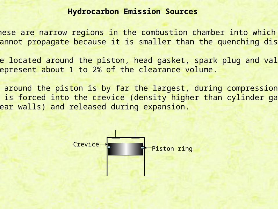
Crevices – these are narrow regions in the combustion chamber into whichthe flame cannot propagate because it is smaller than the quenching distance.
Crevices are located around the piston, head gasket, spark plug and valve seats and represent about 1 to 2% of the clearance volume.
The crevice around the piston is by far the largest, during compression the fuelair mixture is forced into the crevice (density higher than cylinder gas since gas is cooler near walls) and released during expansion.
CrevicePiston ring

Oil layers - Since the piston ring is not 100% effective in preventing oil migration into the cylinder above the piston, oil layers exist within the combustion chamber. This oil layer traps fuel and releases it later during expansion.
Deposits – With continued use carbon deposits build up on the valves, cylinder and piston head. These deposits are porous with pore sizes smaller than thequenching distance so trapped fuel cannot burn. The fuel is released later during expansion.
Liquid fuel – For some fuel injection systems there is a possibility that liquid fuel is introduced into the cylinder past an open intake valve. The less volatilefuel constituents may not vaporize (especially during engine warm-up) and be absorbed by the crevices or carbon deposits.
Flame quenching – It has been shown that the flame does not burn completelyto the internal surfaces, the flame extinguishes at a small but finite distance from the wall. Most of this gas eventually diffuses into the burned gas duringexpansion stroke.
Hydrocarbon Emission Sources

Hydrocarbon Exhaust Process
When the exhaust valve opens the large rush of gas escaping the cylinder drags with it some of the hydrocarbons released from the crevices, oil layer and deposits.
During the exhaust stroke the piston rolls the hydrocarbons distributed along the walls into a large vortex that ultimately becomes large enough that a portion of it is exhausted.
Blowdown ExhaustStroke

Hydrocarbon Exhaust Process
Exhaust valve opens
Exhaust valve closes
The first peak is due to blowdown and the second peak is due to vortex roll upand exhaust (vortex reaches exhaust valve at roughly 290o)
TCBC
17
Hydrocarbon Emission Sources for CI Engines
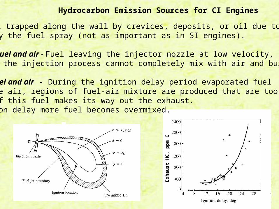
Crevices - Fuel trapped along the wall by crevices, deposits, or oil due to impingement by the fuel spray (not as important as in SI engines).
Undermixing of fuel and air - Fuel leaving the injector nozzle at low velocity, at the end of the injection process cannot completely mix with air and burn.
Overmixing of fuel and air - During the ignition delay period evaporated fuel mixes with the air, regions of fuel-air mixture are produced that are too lean to burn. Some of this fuel makes its way out the exhaust.Longer ignition delay more fuel becomes overmixed.
Exh
aust
HC
, pp
m C

Note for the direct injection diesel the hydrocarbon emission are the worst at light load (long ignition delay)

Particulates
A high concentration of particulate matter (PM) is manifested as visible smoke in the exhaust gases.
Particulates are any substance other than water that can be collected by filtering the exhaust, classified as:
1) solid carbon material or soot2) condensed hydrocarbons and their partial oxidation products
Diesel particulates consist of solid carbon (soot) at exhaust gas temperatures below 500oC HC compounds become absorbed on the surface.
In a properly adjusted SI engines soot is not usually a problem
Particulate can arise if leaded fuel or overly rich fuel-air mixture are used.burning crankcase oil will also produce smoke especially during engine warm up where the HC condense in the exhaust gas.

Most particulate material results from incomplete combustion of fuel HC which occurs in fuel rich mixtures.
Based on equilibrium the composition of the fuel-oxidizer mixture at the onsetof soot formation occurs when x ≥ 2a (or x/2a ≥ 1) in the following reaction:
Particulates (soot)
)()2(2
2 22 sCaxHy
aCOaOHC yx
i.e. when the (C/O) ratio exceeds 1. Experimentally it is found that the criticalC/O ratio for onset of soot formation is between 0.5 and 0.8
The CO, H2, and C(s) are subsequently oxidized in the diffusion flame to CO2 and H2O via the following second stage
OHOHCOOsCCOOCO 2222222 2
1 )(
2
1
Any carbon not oxidized in the cylinder ends up as soot in the exhaust!

21
Particulates are a major emissions problem for CI engines.
Exhaust smoke limits the full load overall equivalence ratio to about 0.7
Particulates and CI Engines
An outstanding problem for diesel engine designers is that in order to reduce NOx one wants to reduce the AFT but this has the adverse effect of decreasingthe amount of soot oxidized, or increases the amount of soot in the exhaust.
= 0.7
= 0.5
= 0.3
One technique for measuring particulate involves diluting the exhaust gas with cool air to freeze the chemistry before measurements

An example of this dilemma is changing the start of injection, e.g., increasing the advance increases the AFT
Crank angle bTC for start of injection
Particulates and CI Engines

Carbon Monoxide
• Carbon monoxide appears in the exhaust of fuel rich running engines.
• For fuel rich mixtures there is insufficient oxygen to convert all the carbon in the fuel to carbon dioxide.
C8H18-air
