pollution incident response management plan · 2017-10-14 · 7.0 hazards 23 8.0 potential...
TRANSCRIPT

MMP Industrial, Mulgrave
9 February 2015
D R A F T
Pollution Incident Response Management Plan
MMP Industrial, 3-5 Hannabus Place, Mulgrave, NSW

AECOM
Pollution Incident Response Management Plan
Z:\MMPData\Documents\Amy B\Government compliance stuff- certificates-licences-reports etc\EPA\MMP-PIRMP(Rev0)-9Feb15.docx Revision B - Revision 0 - 9 February 2015
Pollution Incident Response Management Plan
MMP Industrial, 3-5 Hannabus Place, Mulgrave, NSW
Prepared for
MMP Industrial, Mulgrave
Prepared by
PRISM Risk Eng. Mgt.
37 Pogson Drive, Cherrybroom, NSW, 2126
T +61 2 9484 1730 M +61 411 659 309
ABN 40 552 743 481
9 February 2015
MMP - PIRP
PRISM
© PRISM Risk Eng. Mgt. (-). All rights reserved.
- has prepared this document for the sole use of the Client and for a specific purpose, each as expressly stated in the document. No other party
should rely on this document without the prior written consent of -. - undertakes no duty, nor accepts any responsibility, to any third party who may
rely upon or use this document. This document has been prepared based on the Client’s description of its requirements and -’s experience, having
regard to assumptions that - can reasonably be expected to make in accordance with sound professional principles. - may also have relied upon
information provided by the Client and other third parties to prepare this document, some of which may not have been verified. Subject to the
above conditions, this document may be transmitted, reproduced or disseminated only in its entirety.

AECOM
Pollution Incident Response Management Plan
Z:\MMPData\Documents\Amy B\Government compliance stuff- certificates-licences-reports etc\EPA\MMP-PIRMP(Rev0)-9Feb15.docx Revision B - Revision 0 - 9 February 2015
Quality Information
Document Pollution Incident Response Management Plan
Ref 60282437
Date 9 February 2015
Prepared by Steve Sylvester
Reviewed by Amy Borman
Revision History
Revision Revision
Date Details
Authorised
Name/Position Signature
A 25-Oct-2013 for Client Review Steve Sylvester
Director - Risk
Engineering
B 4-Aug-2014 Incorporation of comments Steve Sylvester
Director - Risk
Engineering
0 9-Feb- 2015 Final Steve Sylvester
Director - Risk
Engineering

AECOM
Pollution Incident Response Management Plan
Z:\MMPData\Documents\Amy B\Government compliance stuff- certificates-licences-reports etc\EPA\MMP-PIRMP(Rev0)-9Feb15.docx Revision B - Revision 0 - 9 February 2015
Table of Contents
Executive Summary Error! Bookmark not defined. 1.0 Introduction 1
1.1 Background 1 1.2 Objectives 1 1.3 Scope of Work 1
2.0 Description of Site Operations 2 2.1 Site Location 2 2.2 Description of Site Operations 2 2.3 Quality and Environmental Standards 11
3.0 PIRMP 13 3.1 What is a Pollution Incident? 13 3.2 Immediate notification 13
4.0 Requirement of the PIRMP 14 5.0 Pollution Incident Notification Protocol 20
5.1 Who do you notify? 20 5.2 What information must you provide? 20 5.3 Coordination with authorities 21
6.0 Notifying a Pollution Incident to Neighbours 22 6.1 Wider Notification 22 6.2 Community communication mechanisms 22 6.3 Information to be provided 22
7.0 Hazards 23 8.0 Potential Pollutants 31 9.0 Testing the Plan 33
9.1 Description and Likelihood of Hazards 34 9.2 Pre-emptive actions to be taken 35 9.3 Inventory of Pollutants 35 9.4 Safety Equipment 35
10.0 References 36
LIST OF TABLES
Table 2-1: List of Dangerous Goods Stored at the MMP Facility 10 Table 5-1: List of Authorities that Must Be Contacted in the Event of a Pollution Incident 20 Table 5-2: MMP Person Responsible for Communications with Authorities 21 Table 8-1: List of Dangerous Goods Stored in Each Depot at the MMP Facility 31
LIST OF FIGURES
Figure 2-1: Location of MMP in the Mulgrave Area 2 Figure 2-2: Site Layout of the MMP Facility Showing Adjacent Properties 3 Figure 2-3: Proposed LPG Storage Area Layout Schematic – MMP Site 5 Figure 2-4: Scaled Drawing of the MMP Site Showing Building Layouts and Drainage Systems 7 Figure 2-5: Plan of a Typical Aerosol Filling Room 9
AECOM
Pollution Incident Response Management Plan
Z:\MMPData\Documents\Amy B\Government compliance stuff- certificates-licences-reports etc\EPA\MMP-PIRMP(Rev0)-9Feb15.docx Revision B - Revision 0 - 9 February 2015
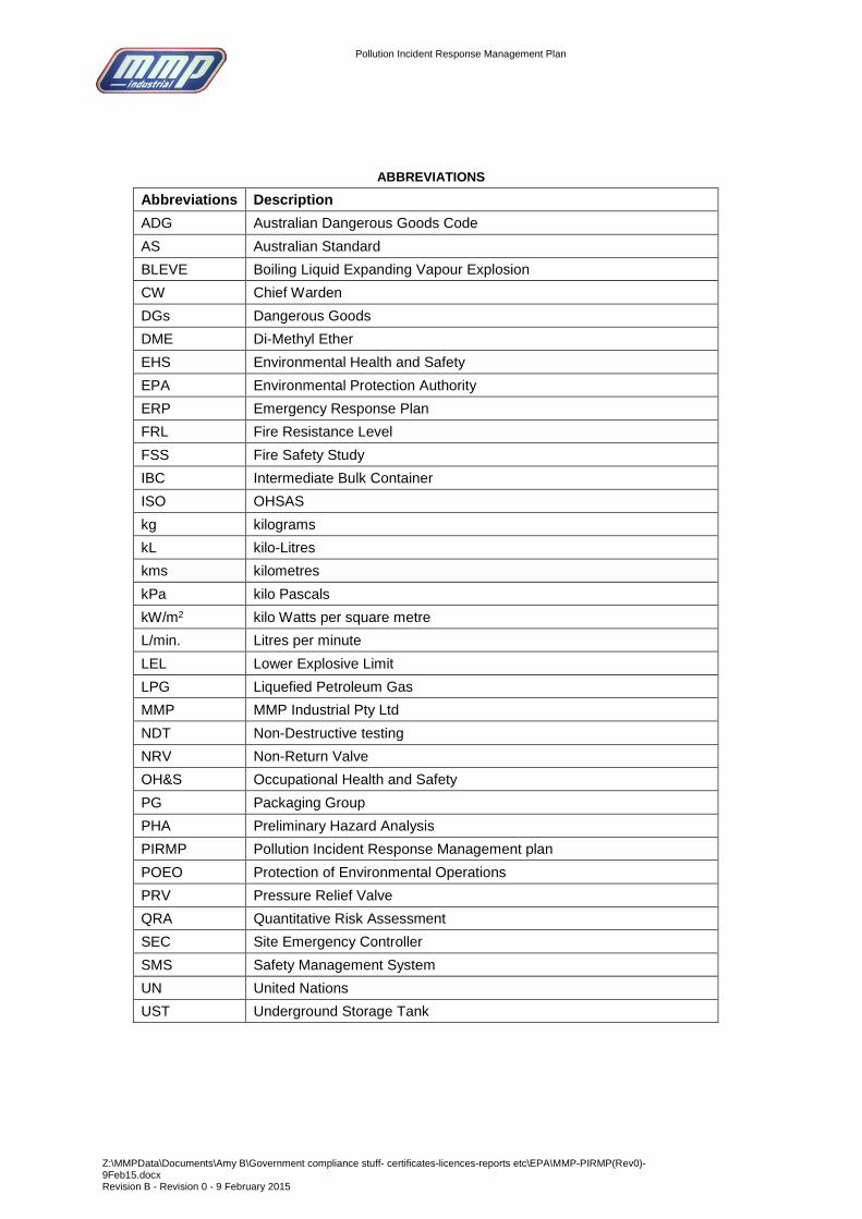
ABBREVIATIONS
Abbreviations Description
ADG Australian Dangerous Goods Code
AS Australian Standard
BLEVE Boiling Liquid Expanding Vapour Explosion
CW Chief Warden
DGs Dangerous Goods
DME Di-Methyl Ether
EHS Environmental Health and Safety
EPA Environmental Protection Authority
ERP Emergency Response Plan
FRL Fire Resistance Level
FSS Fire Safety Study
IBC Intermediate Bulk Container
ISO OHSAS
kg kilograms
kL kilo-Litres
kms kilometres
kPa kilo Pascals
kW/m2 kilo Watts per square metre
L/min. Litres per minute
LEL Lower Explosive Limit
LPG Liquefied Petroleum Gas
MMP MMP Industrial Pty Ltd
NDT Non-Destructive testing
NRV Non-Return Valve
OH&S Occupational Health and Safety
PG Packaging Group
PHA Preliminary Hazard Analysis
PIRMP Pollution Incident Response Management plan
POEO Protection of Environmental Operations
PRV Pressure Relief Valve
QRA Quantitative Risk Assessment
SEC Site Emergency Controller
SMS Safety Management System
UN United Nations
UST Underground Storage Tank

Pollution Incident Response Management Plan
Z:\MMPData\Documents\Amy B\Government compliance stuff- certificates-licences-reports etc\EPA\MMP-PIRMP(Rev0)-9Feb15.docx Revision B - Revision 0 - 9 February 2015
1
1.0 Introduction
1.1 Background
MPP Industrial Pty Ltd (MMP) operates an aerosol filling facility located at 3-5 Hannabus Place, Mulgrave, NSW
(‘the Site’). The facility stores and handles a number of flammable, toxic and corrosive substances, including
liquids and gases. Site operations include the filling of aerosol cans and bottles with various products
predominantly for the car care industry.
As a facility that stores and handles a number of flammable, toxic and corrosive liquids, the Environmental
Protection Authority (EPA) has requested MMP prepare and implement a pollution incident response
management plan (PIRMP). The specific requirements for the PIRMP are set out in Part 5.7A of the POEO Act
and outlined in the NSW EPA Environmental Guidelines: Preparation of pollution incident response management
plans (NSW EPA, March 2012). The new legislation requires the following:
- All holders of environment protection licences must prepare a pollution incident response management plan
(section 153A, POEO Act), however, whilst the site does not require a licence, the EPA has requested a
plan be prepared;
- The plan must include the information detailed in the POEO Act (section 153C) and be in the form required
by the POEO(G) Regulation (clause 98B);
- Licensees must keep the plan at the premises to which the environment protection licence relates;
- Licensees must test the plan in accordance with the POEO(G) Regulation (clause 98E); and
- If a pollution incident occurs in the course of an activity so that material harm to the environment is caused
or threatened, licensees must immediately implement the plan (section 153F, POEO Act).
This document includes the PIRMP for the MMP facility and provides a review of the current pollution incident
reporting processes as part of the Management Systems documented and implemented on the Site.
1.2 Objectives
The objectives of the study are to develop a PIRMP on behalf of MMP for the site to:
- Ensure comprehensive and timely communication about a pollution incident to staff at the premises, the
Environment Protection Authority (EPA), other relevant authorities (Hawkesbury Council, NSW Ministry of
Health, WorkCover NSW and Fire and Rescue NSW);
- Minimise and control the risk of a pollution incident at the MMP facility by identifying the risks and
development of planned actions to minimise and manage these risks; and
- Ensure that the plan is properly implemented by trained staff at the facility, identifying personnel responsible
for implementing it, and ensuring that the plan is regularly tested for accuracy, currency and suitability.
1.3 Scope of Work
The scope of works comprises the following tasks:
- Site inspection to identify potential pollution incidents that may occur on Site and result in an unacceptable
risk of harm to human health or the environment;
- Review of other relevant emergency plans; and
- Development of a Pollution Incident Response Management Plan.

Pollution Incident Response Management Plan
Z:\MMPData\Documents\Amy B\Government compliance stuff- certificates-licences-reports etc\EPA\MMP-PIRMP(Rev0)-9Feb15.docx Revision B - Revision 0 - 9 February 2015
2
2.0 Description of Site Operations
2.1 Site Location
Figures 2.1 shows the regional and site location of the MMP facility at Mulgrave, NSW. The site layout is shown
in Figure 2.2. The description below is given to aid in understanding the site warehousing operations and the
types of hazards that may require emergency response.
Ref: UBD - 2003
Figure 2-1: Location of MMP in the Mulgrave Area
Site Location

Pollution Incident Response Management Plan
Z:\MMPData\Documents\Amy B\Government compliance stuff- certificates-licences-reports etc\EPA\MMP-PIRMP(Rev0)-9Feb15.docx Revision B - Revision 0 - 9 February 2015
3
Figure 2-2: Site Layout of the MMP Facility Showing Adjacent Properties
See Table 2.1 for depot details
and material contents

Pollution Incident Response Management Plan
Z:\MMPData\Documents\Amy B\Government compliance stuff- certificates-licences-reports etc\EPA\MMP-PIRMP(Rev0)-9Feb15.docx Revision B - Revision 0 - 9 February 2015
4
2.2 Land Zoning and Adjacent Land Use
The MMP facility is located in between Hannabus Place and Hudson Pace, Mulgrave, NSW. The land
is zoned 4(a) industrial. The site has an area of about 6 acres and is located on a block of land
between Hudson Place (west) and Hannabus Place (east). The following facilities and businesses are
adjacent to the warehouse facility:
Perfection milk distribution centre - comprising a milk storage facility with sheet metal walls and roof
(internal refrigerators and loading dock area - boundary south - east);
Aluminium windows and doors manufacturing plant – comprising a factory unit with masonry walls (boundary
south-east);
Motor vehicle importer – comprising a warehouse building and showroom of sheet metal walls and roof
(boundary south west)
A packaging manufacturing plant – comprising buildings of sheet metal walls and roofs (boundary south-
west);
Hytec cement production plant – comprising silos, conveyors, sand storage bins and truck loading areas
(boundary north-west);
Computer embroidery plant – comprising concrete tilt-up panel building (boundary north);
Warehouse facility (boundary north); and
Vehicle repair facility – comprising sheet metal building (boundary east).
The location of these facilities in relation to the MMP site is shown on Figure 2.2. The closest zoned residential
area is at McGraths Hill about 1.5-2kms from the site.
2.3 General Operations
The site is predominantly used for the filling and storage of aerosols, with some small container (bottles) filling,
prior to delivery to commercial operators and retailers. Raw materials (e.g. containers and liquid products) are
brought to site in bulk. The containers are stored in warehouses and the bulk liquids in above ground and
underground tanks. Filled products are located in dedicated dangerous goods stores prior to shipping to retailers.
Containers are filled in bottling and can filling lines at various locations around the site. Containers/bottles are
placed on filing lines and the bulk product delivered by pipework to the filling heads. The filled containers/bottles
are then removed from the filling line and packaged in cardboard cartons and loaded to pallets. The pallets are
then stored in warehouses on site ready for delivery to retailers as required.
2.4 LP Gas Storages
Liquefied Petroleum Gas (LPG) is be stored in a single tank farm at the site. The existing risk assessment study
identified that two LPG tank farms were installed at the site. However, the smaller of the two tank farms (located
on the southern side of Warehouse 1), was removed in 2006.
The LPG tank farm stores the liquefied gas in two forms; propane/butane blend and di-methyl-ether. These gases
are used to fill the aerosols and provide the propellant for the material within the aerosol can. The propane/butane
is stored in two tanks, each of 63 kL capacity. The di-methyl-ether is stored in a single tank of 43 kL capacity.
Figure 2.2 shows the location of the storage.
The operating pressures of the gases are:
LPG – 760 kPa; and
Di-methyl-ether – 510 kPa.

Pollution Incident Response Management Plan
Z:\MMPData\Documents\Amy B\Government compliance stuff- certificates-licences-reports etc\EPA\MMP-PIRMP(Rev0)-9Feb15.docx Revision B - Revision 0 - 9 February 2015
5
Figure 2-3: Proposed LPG Storage Area Layout Schematic – MMP Site
The liquefied gas storage consists of 4 tanks, associated pipework, pumps and a tank loading facility (i.e. tanker
and transfer point). It is noted that one of the four tanks is not in use and is currently inerted with nitrogen Figure
2.3 shows the liquefied gas storage facility layout. The facility components are:
2 x 63kL tanks;
2 x 42kL tanks;
associated pipework and fittings,
LPG transfer pumps; and
LPG tanker unloading facilities.
Each storage tank has been installed to AS1596-2000, “The Storage and Handling of LP Gas” (Ref.1). This
standard requires stringent LPG storage design and compliance with safety requirements.
2.5 LPG Tanker to LPG Tanks Transfer
The tanks are filled using a liquefied gas transport vehicle, which is a dedicated tanker truck used for the transport
of liquefied gases. The transport of these gases is a carefully controlled industry, which is regulated by the NSW
Government.
The tank storage has been fitted with a liquefied gas transfer point, which has been designed in accordance with
AS1596 to ensure the appropriate safety features were installed as part of the design. A brief transfer procedure
is summarised below. It is noted that this procedure is a summary only and the actual operation contains many
more steps, however, these are in compliance with AS1596.
0 5 10 15 20 5 1
4
3
2
LPG
LPG
DME
Warehouse 5
Warehouse 1
Road Tanker
Tanker
unloading
point
Empty Tank
Boundary Fence
Armco Fence

Pollution Incident Response Management Plan
Z:\MMPData\Documents\Amy B\Government compliance stuff- certificates-licences-reports etc\EPA\MMP-PIRMP(Rev0)-9Feb15.docx Revision B - Revision 0 - 9 February 2015
6
The trucks enter the site from Hannabus Place and park adjacent to the transfer point. The tanker driver/operator
connects the flexible transfer hoses to the tanker vehicle and then to the transfer point pipework. Dedicated
connections for the transfer of the liquefied gas are used for this purpose. Once connected, the tanker driver
checks the connections prior to opening the appropriate valves. The liquefied gas is then pumped to the tanks
using truck mounted transfer pump. The tanker driver continually monitors the tank contents and stops the
transfer once the tanks have reached the desired level. On completion of the transfer, the driver purges the lines
and isolates the system using the valves installed on the transfer pipework. Once purged, the flexible lines are
removed from the system and stored on the tanker truck. The tanker driver then leaves the site on completion of
the transfer operation.
A number of safety features are installed to minimise the potential for incidents during the transfer, these are
summarised below.
Driveaway Prevention – the truck is fitted with a system that applies the truck brakes and prevents the
driver from moving the vehicle whilst the flexible hoses are connected to the vehicle.
Weak Coupling – a weak coupling joint is installed immediately after the flexible line connection which
breaks in the event a driveaway occurs when the hose is connected.
Snap Shut Valve – a snap shut valve is installed immediately after the weak coupling. In the event the
coupling breaks, the snap shut valve isolates any potential gas leaks (NRV’s also prevent backflow from the
tank).
Earthing Connection – an earthing lead is provided so that the driver can “electrically” connect the vehicle
to the storage system, eliminating the potential for sparks from static build up.
Isolation and Non-Return Valves – are installed on the delivery lines to prevent liquefied gas flow back
down the line in the event of a release at the flexible line.
Training – liquefied gas tanker drivers are dedicated operators trained in the handling of liquefied gases.
Each driver is trained in the transfer procedure and the emergency response requirements in the event of an
incident.
2.6 Product Transfer for Use
The storage tanks hold a mixture of butane and propane (LPG), which is delivered to site in premixed quantities.
These products are used in various locations around the aerosol manufacturing areas on site. The products are
currently transferred using pumps and 50mm pipework.
All current LPG tanks on site are fitted with both manual and automatic isolation valves in accordance with the
requirements of AS1596. Additional safety features of the LPG systems are summarised below.
Pressure Relief Valves (PRV) – will be installed on each tank to eliminate the potential for tank
overpressure. The PRVs will be set to operate above the gas operating pressure but well below the failure
pressure of the vessel.
Hydrostatic PRVs – will be installed on pipelines where liquefied gas may be trapped between isolation
valves (hence, trapped liquid cannot expand and cause line failure).
Automatic Isolation Valves – that will operate on gas detection, fire detection or activation of the
emergency shut-off system (button).
Gas Detectors – installed around the tanks and storage area to detect gas and alarm well below the lower
explosive limit (LEL).
Fire Detection & Response – plastic air lines installed on auto-isolation valves. In the event of fire, air lines
fail and valves are automatically closed, isolating the gas in the tank and starving the fire of fuel.
Excess Flow Valves – installed at the liquid discharge line from each tank. In the event of line rupture,
excess flow valves automatically close, preventing gas discharge through the rupture.

Pollution Incident Response Management Plan
Z:\MMPData\Documents\Amy B\Government compliance stuff- certificates-licences-reports etc\EPA\MMP-PIRMP(Rev0)-9Feb15.docx Revision B - Revision 0 - 9 February 2015
7
Figure 2-4: Scaled Drawing of the MMP Site Showing Building Layouts and Drainage Systems
Storm Water Drain
Storm Water Drain Pits
(water inlet)
Storm Water Drain
discharge isolation valve –
activated to isolate potential
pollutant discharge offsite

Pollution Incident Response Management Plan
Z:\MMPData\Documents\Amy B\Government compliance stuff- certificates-licences-reports etc\EPA\MMP-PIRMP(Rev0)-9Feb15.docx Revision B - Revision 0 - 9 February 2015
8
2.7 Product Mixing Operations
A number of paint and flammable/combustible product mixing/manufacturing machines are located in various
buildings around the site. Figure 2.4 shows a scaled drawing of the MMP site with the locations of the various
buildings and the aerosol gassing lines, and rooms, and the bottle filling plants. The product mixing machines are
located adjacent to the filling lines and are used to manufacture the paint and other flammable/combustible
products that are filled to aerosol cans. The operation requires the loading of various chemicals (resins, thinners,
tints, etc.) to the mixers, which combine the materials to manufacture the paint/flammable-combustible product.
The materials are loaded from 205 Litre or a variety of smaller containers (e.g. 25 Litres) or from bulk storage
tanks located external to the filling line buildings. The location of the bulk storage tanks (underground) are shown
on Figure 2.4. When drums are used for filling they are lifted using a dedicated drum lifting device. This provides
a lift and tilt mechanism which aids in the loading of materials to the mixers. Raw materials in drums are delivered
to by truck. Drums are stored on pallets and are transferred to the various Dangerous Goods stores using forklift
trucks. When bulk tanks are used for filling, product is transferred using a pump. Bulk tanks are filled from road
tankers that deliver raw materials in bulk directly to the underground tanks using a flexible hose. The tanks are
filled by gravity transfer.
Once loaded, lids are placed on the mixer pots and the mixing process commenced. The lids are fitted with
exhaust ventilation, which extracts vapours from the mixer and exhausts them to the exterior of the building.
Once mixed, the paint is transferred to 205 Litre drums ready for use in the aerosol or bottle filling operation.
In some locations around the site, the product is mixed in batching tanks, which are located close to the filling
point. Pipework is used to transfer the products directly to the injection heads on the filling line. Product is pumped
from raw materials tanks into the batching tank, which is fitted with a stirring device. The product is mixed over a
period of time prior to transfer to the filling line. Once prepared, the product is pumped to the filling line for loading
to the cans/bottles.
2.8 Aerosol and Bottle Filling Operations
Aerosol cans are filled in various locations around the site. Dedicated aerosol filling lines are used for the filling of
cans with product and propellant (LPG). Figure 2.5 shows a diagrammatic layout of a typical aerosol filling
operation. The product is mixed in either product mixing tanks or 205 Litre drums. The tanks and/or drums are
located adjacent to the line for injection into the cans using the filling heads.
An example of a batching operation is given below for a water based product, however, flammable and
combustible materials may be used, in lieu of water, for specific products such as paint and degreasers. The
batching tanks is first filled with water and the products are loaded to the mixing tank from either 25 litre, 205 litres
drums or raw material product tanks. Where 25 litre drums are used, the drums are lifted to a tank filling access
platform, using a forklift truck, and manually poured into the tank via the manhole. 205 Litre drums are lifted using
a forklift truck and positioned over the manhole cover. The operator then opens the tap (installed on the drum
earlier) to transfer the contents to the tank. The products are then mixed prior to delivery to the filling line. Where
a tank is used for raw material transfer, the material is pumped to the batching tank.
Once the batched mix is complete a centrifugal pump is used to transfer the mixed product to the filling line. This
is performed via underfloor pipework, which delivers the product to a small float-operated ready use tank adjacent
to the filling head. As the cans progress along the conveyor, the filling head and attached fill tube is lowered and
the tube enters the can top. The product (liquid) is then filled to the can and the fill head/tube retracted when full.
This process is repeated for each can. The same principle is used to fill bottles.
The 205 Litre drums are used predominantly for the mixing of paint prior to filling cans. Paint mixing is described
in Section 2.7. The paint is then transferred to 205 Litre drums and transported to the required filling area. The
drum lids are removed and a mixer and withdrawal spear placed in the drum. Drums remain on pallets throughout
the whole operation and are not handled.
For aerosol gassing, the cans, which now contain product and are moving down the conveyor, are fitted manually
with a product release cap. This is crimped onto the can using a cap crimping machine. The cans then pass to a
conveyor, which feeds them through a small slot in the factory wall to a gassing head. The gassing assembly is
located inside a concrete block room, which is fitted with gas detection and gas isolation valves, activated in the
event of gas detection. Propane/Butane gas mix (500kPa) is used as the propellant, which is loaded to the can

Pollution Incident Response Management Plan
Z:\MMPData\Documents\Amy B\Government compliance stuff- certificates-licences-reports etc\EPA\MMP-PIRMP(Rev0)-9Feb15.docx Revision B - Revision 0 - 9 February 2015
9
using a gassing head. Once filled with gas, the cans return to the factory, via conveyor, through a small slot in the
wall.
Figure 2-5: Plan of a Typical Aerosol Filling Room
2.9 Raw Materials, Product and Packaging Storage
Raw materials and product are stored in a number of locations around the site. These are detailed in Figure 2.4.
Raw materials are stored in bulk tanks or 205 litres drums. Tanks and drum store locations are shown on Figure
2.4.
Once the cans are filled, they are manually packed into boxes. The boxes are taped and stacked on a pallet,
which is transferred to the Dangerous Goods store when full. Products are then transported to market as required.
2.10 Dangerous Goods Stored On-Site
MMP stores a number of Dangerous Goods (DGs) for use in the manufacture of aerosols and filling of bottles.
These are:
Class 2.1 Flammable Gas;
Class 3 Flammable Liquid;
Class 8 Corrosive Liquids; and
Class 6.1 Toxic Substances.
Whilst other materials are stored and used on-site, these are non-dangerous and are used in a number of bottle
and aerosol filling lines. In addition to the materials stored and used for the filling of aerosols and bottles, MMP
stores containers (cans and bottles) that are filled as part of the facility operations.
Table 2.1 lists the Dangerous Goods storage details (types, quantities, UN.No., Class and PG).
Double swinging door
Rotary table, crimping head and entry/exit lines to gas filling room
Factory Wall
Factory Wall
Rotary table, gassing head
AS
AL
G
G
Legend
AS - Alarm Siren
AL - Alarm Light
G - Gas Detector
Not to Scale
Slots in the wall for entry and exit of aerosol cans to and from the gassing room
Extraction Ducts for gassing room ventilation

Pollution Incident Response Management Plan
Z:\MMPData\Documents\Amy B\Government compliance stuff- certificates-licences-reports etc\EPA\MMP-PIRMP(Rev0)-9Feb15.docx Revision B - Revision 0 - 9 February 2015
10
Table 2-1: List of Dangerous Goods Stored at the MMP Facility
Depot No. and Name
of DG
UN.No. Class PG Quantity Stored Storage Type &
Location*
Depot N1 – LPG 1075 2.1 - 63kL (32 tonnes) Above Ground Tank
East of the Aerosol store
and compressor house
Depot N2 – LPG 1075 2.1 - 63kL (32 tonnes)
Depot N2 – LPG 1075 2.1 - 45kL (23 tonnes)
Depot N4 – LPG 1075 2.1 - 45kL (23 tonnes)
Depot 2 – LPG 1075 2.1 - 7.5kL (3.5 tonnes) Above Ground Tank
Adjacent to the southern
most boundary of the site Depot 3 – LPG 1075 2.1 - 7.5kL (3.5 tonnes)
Depot 19 – LPG 1075 2.1 - 7.5kL (3.5 tonnes)
Depot 20 – LPG 1075 2.1 - 7.5kL (3.5 tonnes)
Depot 21 – LPG 1075 2.1 - 7.5kL (3.5 tonnes)
Depot N5 – Acetone 1090 3 II 10,000 Litres Underground Tanks
West of Warehouse 11 Depot N6 – Xylene 1307 3 II 10,000 Litres
Depot N7 – Acetone 1090 3 II 55,000 Litres Underground Tanks
West of Warehouse 7 Depot N8 – White
Spirit
1300 3 II 55,000 Litres
Depot N9 – White
Spirit
1300 3 II 55,000 Litres
Depot N10 – Toluene 1294 3 II 55,000 Litres
Depot 17 – Acetone 1090 3 II 10,000 Litres Underground Tanks
Between warehouses 5
and 7
Depot 15 – Toluene 1294 3 II 20,000 Litres
Depot 16 – Toluene 1294 3 II 20,000 Litres
Depot 11 – White Spirit 1300 3 II 20,000 Litres Underground Tanks
Immediately west of
Warehouse 4
Depot 10 – White Spirit 1300 3 II 20,000 Litres
Depot 1 – White Spirit 1300 3 II 20,000 Litres Underground Tank
Southern corner of
Warehouse 1
Depot WH5-1 –
Aerosol
1950 2.1 - 300,000kg Warehouse 5
Depot N11 – Aerosol 1950 2.1 - 22,500kg Warehouse 9
Depot N12 – Aerosol 1950 2.1 - 25,000kg Warehouse 10
Depot N13 – Paint
Related Products
1263 3 III 15,000 Litres Warehouse 8
(Paint Tints)
Depot 12 - LPG 1075 2.1 - 500 Litres Cylinder Store
West of Warehouse 6
(Minor Storage)

Pollution Incident Response Management Plan
Z:\MMPData\Documents\Amy B\Government compliance stuff- certificates-licences-reports etc\EPA\MMP-PIRMP(Rev0)-9Feb15.docx Revision B - Revision 0 - 9 February 2015
11
Table 2-1: List of Dangerous Goods Stored at the MMP Facility
Depot No. and Name
of DG
UN.No. Class PG Quantity Stored Storage Type &
Location*
Depot WHS3-1 -
Dichloromethane
Trichloro ethylene
1593
1897
6.1
6.1
II
II
1000 Litres
9000 Litres
Warehouse 3
Depot WHS3-2 –
Ethanolamine
2491 8 III 1600 Litres Warehouse 3
Depot WHS2-1 –
Sodium Nitrate
1500 5.1 300kg Warehouse 2
Depot WHS1-2 –
Diesel
- C1 - 2100 Litres Warehouse 1
Depot WHS1-1 -
Ethanolamine
2491 8 III 205 Litres Warehouse 1
Depot WHS7 –
Flammable Solid
Organic, NOS
1325 4.1 500kg Warehouse 7
Depot 4 – Ethanol
(ethyl alcohol)
1179 3 II 20,000 Litres Package Store (205 Litre
drums)
South west of Warehouse
1
* see Figure 2.5 for map of storage locations
All Dangerous Goods on site are stored in accordance with the Australian Dangerous Goods Code (Ref.2), the
WHS Regulation (2011) (Ref.3), and AS 1940-2004 (Ref.4). WorkCoverNSW has been notified of the storage
quantities and provisions at the site.
2.11 Quality and Environmental Standards
The MMP organisation operates under the principles of a number of international standards, including ISO and
Australian Standards. The principles contained within the following standards are implemented at the MMP
Mulgrave site:
ISO14000 - 2004 (Series) – Environmental management Systems.
OHSAS18000 – 2007 (Series) ,Occupational Health and Safety Management Systems.
ISO9000 – 2005 (Series), Quality Management Systems.
The assessment conducted in this review included a review of the current system to identify the appropriate
procedures applicable to emergency response, pollution control and incident reporting.
A review of the relevant procedures, currently used at MMP, is presented in the following table.
Title Applicability Comments
Environmental Health & Safety
(EHS) incident Statutory Reporting
and Investigation Process
SMS 4.4.3 and ERP (Section 12)
Defines the statutory requirements
for EHS incident reporting and
procedure for internal reporting and
conducting incident investigation
Applies to internal incident report
and reporting to WorkCover.
Also applies to any incident and
reporting to appropriate government
agencies.

Pollution Incident Response Management Plan
Z:\MMPData\Documents\Amy B\Government compliance stuff- certificates-licences-reports etc\EPA\MMP-PIRMP(Rev0)-9Feb15.docx Revision B - Revision 0 - 9 February 2015
12
Title Applicability Comments
Emergency Response Plan (ERP)
Provides a planned and coordinated
response to emergency situations
related to environmental health and
safety.
Includes responsibilities,
procedures, training for emergency
drills.
Crisis Management Plan
(ERP)
Assists in the response,
management and recovery of a
crisis situation directly impacting the
people or operations of MMP.
The Crisis Management Plan is
incorporated within the ERP and
includes the responsibility of the
Site personnel for crisis
management and the notification
process that should be completed.
Environmental Aspect and Impact
Analysis
Describes the methods used to
identify the environmental aspects
and impacts, how to assess the
significance of the aspects and
impacts and how they are
managed.
Environmental Aspects and Impacts
register has not been developed for
the site – Recommend an Aspects
and Impact Register be developed
for the site – Register to be
developed by end Oct 14.
Emergency Preparedness and
Response
(Risk Assessment & Risk Register,
ERP)
Describes the process of identifying
the potential for and response to
Environmental and OHS incidents
and emergency situations and the
actions to prevent and mitigate the
likely illness that may be
associated.
Procedures should be documents
specifically for emergencies such
as liquid DGs release and clean-up;
release of aerosol can contents,
dropped drums, LPG release, etc.
An inventory of safety/incident
response equipment should be
included in this procedure.
Needs to be updated annually.
SMS document includes
requirements for PIRM updates.
Aspect/Impact Analysis for
Operations
Identifies the works activities,
aspects and impacts specific to the
MMP operations at the Site in
Mulgrave
Includes all the work activities for
the operations conducted at the
Site – see Various documents
including SMS, ERP and Risk
Assessments
Hazard Identification and Risk
Assessment
Preliminary Hazard Analysis (PHA)
Documents the identification of
hazards relating to occupational
health and safety, evaluate the risks
associated with these hazards and
to ensure that appropriate actions
are taken to manage the risks
involved.
Relates to hazards and risks at the
site including OH&S, process
hazards, major hazards, liquid/gas
releases and spill retention and
environmental impacts from
potentially contaminated fire water.
Environmental Occupational Health
& Safety (OHS) Accident/Incident
and Non-Conformance
Defines the responsibility and
authority for the handling of
investigation of Environmental and
OH&S accidents, incidents and
non-conformances as well as the
mitigation action, the
implementation and verification for
corrective/preventive action.
Outlines procedures for handling of
investigations of environmental,
OH&S incidents and non-
conformances.

Pollution Incident Response Management Plan
Z:\MMPData\Documents\Amy B\Government compliance stuff- certificates-licences-reports etc\EPA\MMP-PIRMP(Rev0)-9Feb15.docx Revision B - Revision 0 - 9 February 2015
13
3.0 PIRMP
This pollution incident response management plan (PIRMP) has been prepared for the MMP facility in Mulgrave,
NSW. The PIRMP sets out the procedure to be followed in the event of a pollution incident at the site.
3.1 What is a Pollution Incident?
In accordance with the POEO Act (section 153F), if a pollution incident occurs in the course of an activity so that
material harm to the environment is caused or threatened, the person carrying on the activity must immediately
implement the PIRMP.
‘Pollution Incident ‘is defined in the dictionary of the POEO Act as:
A pollution incident means an incident or set of circumstances during or as a consequence of which there is,
or is likely to be, a leak, spill or other escape or deposit of a substance, as a result of which pollution has
occurred, is occurring or is likely to occur. It includes an incident or set of circumstances in which a
substance has been placed or disposed of on premises, but it does not include an incident or set of
circumstances involving only the emission of any noise.
‘Material Harm’ is defined in section 147 of the POEO Act. Material harm includes on-site harm, as well as harm
to the environment beyond the premises where the pollution incident occurred.
147 Meaning of material harm to the environment
(1) For the purposes of this Part:
(a) harm to the environment is material if:
(i) it involves actual or potential harm to the health or safety of human beings or to ecosystems
that is not trivial, or
(ii) it results in actual or potential loss or property damage of an amount, or amounts in
aggregate, exceeding $10,000 (or such other amount as is prescribed by the regulations), and
(b) loss includes the reasonable costs and expenses that would be incurred in taking all reasonable
and practicable measures to prevent, mitigate or make good harm to the environment.
(2) For the purposes of this Part, it does not matter that harm to the environment is caused only in the
premises where the pollution incident occurs.
3.2 Immediate notification
EPL licensees and anyone carrying on an activity or occupying a premises who becomes aware of a pollution
incident are required to report the pollution incident immediately (under section 148 of the POEO Act). (Formerly
the requirement was ‘as soon as practicable’).
‘Immediate’ means licensees or operators need to report pollution incidents promptly and without delay. There is a
$2 million maximum penalty for failure to notify of a pollution incident in accordance with the requirements of the
POEO Act.
The duty to notify does not apply to a pollution incident involving only the emission of an odour, and does not
include an incident or set of circumstances involving only the emission of noise.

Pollution Incident Response Management Plan
Z:\MMPData\Documents\Amy B\Government compliance stuff- certificates-licences-reports etc\EPA\MMP-PIRMP(Rev0)-9Feb15.docx Revision B - Revision 0 - 9 February 2015
14
4.0 Requirement of the PIRMP
The legislative requirements of the PIRMP and where these requirements have been met in this document are
shown in the table below. Each of the legislative requirements is listed in the table below and a reference provided
as to where compliance for the specific section of the legislation is found. The parts of the PIRMP that must be
made publicly available are noted in the table below, row 98D.
Legislation Requirement Where this requirement is met
Must be
Publicly
Available?
POEO Act:
Part 5.7A Duty to prepare and implement pollution incident response management plans
153A - Duty of
licence holder to
prepare pollution
incident response
management plan
The holder of an environment
protection licence must prepare a
pollution incident response
management plan that complies
with this Part in relation to the
activity to which the licence relates.
It is noted that MMP does not hold
or require a licence, however, the
EPA has requested MMP prepare a
PIRMP.
This PIRMP in conjunction with the
following MMP documents:
Emergency Response Plan (ERP)
Crisis Management Plan
(incorporated in the ERP)
Environmental Health & Safety
(EHS) incident Statutory Reporting
and Investigation Process
(included in the SMS & ERP)
Emergency Preparedness and
Response (Risk Assessment
documents and ERP)
Work instructions and procedures.
153C -
Information to be
included in plan
A pollution incident response
management plan must be in the
form required by the regulations
and must include the following:
a) the procedures to be followed
by the holder of the relevant
environment protection licence,
or the occupier of the relevant
premises, in notifying a pollution
incident to:
i) the owners or occupiers of
premises in the vicinity of
the premises to which the
environment protection
licence or the direction
under section 153B relates,
and
Refer to Section 6.0 of this PIRMP.
ii) the local authority for the
area in which the premises
to which the environment
protection licence or the
direction under section 153B
relates are located and any
area affected, or potentially
affected, by the pollution,
and
Refer to Section 5.0 of this PIRMP –
the contact details, of the local
regulatory authority, is included in
Table 5.1.
iii) any persons or authorities
required to be notified by
Part 5.7
Refer to Section 5 of this PIRMP.
Table 5.1 lists the various contact
details for the authorities required to
be contacted.
b) a detailed description of the Response procedures are specified in:

Pollution Incident Response Management Plan
Z:\MMPData\Documents\Amy B\Government compliance stuff- certificates-licences-reports etc\EPA\MMP-PIRMP(Rev0)-9Feb15.docx Revision B - Revision 0 - 9 February 2015
15
Legislation Requirement Where this requirement is met
Must be
Publicly
Available?
action to be taken, immediately
after a pollution incident, by the
holder of the relevant
environment protection licence,
or the occupier of the relevant
premises, to reduce or control
any pollution
Emergency Response Plan
Crisis Management Plan
(within the ERP)
c) the procedures to be followed
for co-ordinating, with the
authorities or persons that have
been notified, any action taken
in combating the pollution
caused by the incident and, in
particular, the persons through
whom all communications are to
be made
Refer to Section 5.3 of this PIRMP.
153D - Keeping of
plan
A person who is required to prepare
a pollution incident response
management plan under this Part
must ensure that it is kept at the
premises to which the relevant
environment protection licence
relates, or where the relevant
activity takes place, and is made
available in accordance with the
regulations.
A copy of the PIRMP will be kept on-
site at MP, Mulgrave.
153E - Testing of
plan
A person who is required to prepare
a pollution incident response
management plan under this Part
must ensure that it is tested in
accordance with the regulations.
Testing of the PIRMP will be
undertaken in accordance with the
regulations as set out in Section 9 of
this PIRMP.
153F-
Implementation of
plan
If a pollution incident occurs in the
course of an activity so that material
harm to the environment (within the
meaning of section 147) is caused
or threatened, the person carrying
on the activity must immediately
implement any pollution incident
response management plan in
relation to the activity required by
this Part.
Noted – the plan will be implemented
in the unlikely event of an incident.
Protection of the Environment Operations (General) Regulation 2009:
Part 3A Pollution incident response management plans
98B - Form of
plan
1) A plan is to be in written form This PIRMP meets the requirements
of the written form plan.
2) A plan may form part of another
document that is required to be
prepared under or in accordance
with any other law so long as the
information required to be
included in the plan is readily
identifiable as such in that other
document.
As noted, this PIRMP in conjunction
with the following MMP documents:
Emergency Response Plan (ERP)
Crisis Management Plan
(incorporated within the ERP)
Environmental Health & Safety
(EHS) incident Statutory Reporting
and Investigation Process (within

Pollution Incident Response Management Plan
Z:\MMPData\Documents\Amy B\Government compliance stuff- certificates-licences-reports etc\EPA\MMP-PIRMP(Rev0)-9Feb15.docx Revision B - Revision 0 - 9 February 2015
16
Legislation Requirement Where this requirement is met
Must be
Publicly
Available?
the ERP and SMS
Emergency Preparedness and
Response (ERP)
Work instructions and procedures.
98C - Additional
matters to be
included in plan
1) General
The matters required under
section 153C (d) of the Act to be
included in a plan are as follows:
a) a description of the hazards
to human health or the
environment associated with
the activity to which the
licence relates (the relevant
activity),
Refer to Section 7 of this PIRMP.
Hazards associated with the
operations that may impact people (on
and offsite), plant and the environment
is covered in the quantitative risk
assessment conducted in the
Preliminary Hazard Analysis (PHA)
study.
b) the likelihood of any such
hazards occurring, including
details of any conditions or
events that could, or would,
increase that likelihood
Refer to Section 7 of this PIRMP. The
likelihood of hazards associated with
the operations that may impact people
(on and offsite), plant and the
environment is covered in the
quantitative risk assessment
conducted in the Preliminary Hazard
Analysis (PHA) study.
c) details of the pre-emptive
action to be taken to minimise
or prevent any risk of harm to
human health or the
environment arising out of the
relevant activity
Refer to Section 7 of this PIRMP.
Pre-emptive actions that are taken to
avert hazards associated with the
operations that may impact people (on
and offsite), plant and the environment
is covered in the quantitative risk
assessment conducted in the
Preliminary Hazard Analysis (PHA)
study.
The site Dangerous Goods (DG) risk
assessment also included actions
(safeguards) that should be applied to
minimise the impacts of hazards at the
Site.
d) an inventory of potential
pollutants on the premises or
used in carrying out the
relevant activity.
Refer to Section 7 of this PIRMP.
A Dangerous Goods risk assessment
has been conducted for the site which
includes a detailed list of hazardous
materials that may impact people (on
and offsite), plant and the
environment.
e) the maximum quantity of any
pollutant that is likely to be
stored or held at particular
locations (including
underground tanks) at or on
the premises to which the
licence relates
Refer to Section 7 of this PIRMP.
A Dangerous Goods risk assessment
has been conducted for the site which
includes a detailed list of hazardous
materials that may impact people (on
and offsite), plant and the
environment, and the locations of all
goods held at the site.
f) a description of the safety
equipment or other devices
Refer to:
Emergency Response Plan (ERP)

Pollution Incident Response Management Plan
Z:\MMPData\Documents\Amy B\Government compliance stuff- certificates-licences-reports etc\EPA\MMP-PIRMP(Rev0)-9Feb15.docx Revision B - Revision 0 - 9 February 2015
17
Legislation Requirement Where this requirement is met
Must be
Publicly
Available?
that are used to minimise the
risks to human health or the
environment and to contain or
control a pollution incident
Preliminary Hazard Analysis Study
g) the names, positions and 24-
hour contact details of those
key individuals who:
i) are responsible for
activating the plan, and
ii) are authorised to notify
relevant authorities under
section 148 of the Act,
and
iii) are responsible for
managing the response to
a pollution incident
Refer to the site ERP. The appendices
in the ERP provide contact details,
including phone numbers.
h) the contact details of each
relevant authority referred to
in section 148 of the Act
Refer to Section 5.0 of this PIRMP
(see Table 5.1 for contact details of
each authority)
The ERP also contains contact details
of the authorities and requirements for
contacting regulators, including reports
and documents to be submitted after
an incident has occurred.
i) details of the mechanisms for
providing early warnings and
regular updates to the owners
and occupiers of premises in
the vicinity of the premises to
which the licence relates or
where the scheduled activity
is carried on
Refer to Section 6.0 of this PIRMP.
The ERP contains details of adjacent
sites and contact phone numbers for
adjacent sites.
j) the arrangements for
minimising the risk of harm to
any persons who are on the
premises or who are present
where the scheduled activity
is being carried on
Refer to the following procedures:
Emergency Response Plan (ERP),
including Emergency Preparedness
and Response procedures
incorporated within the ERP
k) a detailed map (or set of
maps) showing the location of
the premises to which the
licence relates, the
surrounding area that is likely
to be affected by a pollution
incident, the location of
potential pollutants on the
premises and the location of
any stormwater drains on the
premises
Refer to Figure 2.1 and Figure 2.2 of
this PIRMP for materials storage
locations. See Table 2.1 for details of
material quantities held in each
storage depot. See Figure 2.4 for
details of stormwater system and drain
locations, including drain system
isolation point.
l) a detailed description of how
any identified risk of harm to
human health will be reduced,
Refer to
Emergency Response Plan (ERP)
Preliminary Hazard Analysis (PHA)

Pollution Incident Response Management Plan
Z:\MMPData\Documents\Amy B\Government compliance stuff- certificates-licences-reports etc\EPA\MMP-PIRMP(Rev0)-9Feb15.docx Revision B - Revision 0 - 9 February 2015
18
Legislation Requirement Where this requirement is met
Must be
Publicly
Available?
including (as a minimum) by
means of early warnings,
updates and the action to be
taken during or immediately
after a pollution incident to
reduce that risk
study prepared for the site,
including a Quantitative Risk
Assessment (QRA)
m) the nature and objectives of
any staff training program in
relation to the plan
Training for the PIRMP will be
conducted in conjunction with in
Emergency Response Training,
n) the dates on which the plan
has been tested and the
name of the person who
carried out the test
Refer to Section 7 of this PIRMP.
o) the dates on which the plan is
updated
Refer to Section 7 of this PIRMP.
p) the manner in which the plan
is to be tested and
maintained.
Refer to Section 7 of this PIRMP.
2) Trackable waste transporters
Environmental Treatment
Solutions
Contact: Geoff O’Dell
Phone: 02 9605 8534
Address:12 Shaw Road, Ingleburn,
NSW
Trackable wastes are collected by
Environmental Waste Solutions and
transferred to a licensed disposal
facility. All wastes are tracked using
the required EPA documentation.
Contact details of the trackable wastes
company are included in the ERP and
listed in the adjacent cell.
98D - Availability
of plan
1) A plan is to be made readily
available:
a) to an authorised officer on
request, and
The PIRMP will be made readily
available to an authorised EPA officer
on request.
b) at the premises to which the
relevant licence relates, or
where the relevant activity
takes place, to any person
who is responsible for
implementing the plan.
The PIRMP will be kept onsite at
Mulgrave.
2) A plan is also to be made
publicly available in the
following manner within 14
days after it is prepared:
a) in a prominent position on a
publicly accessible website
of the person who is
required to prepare the
plan,
b) if the person does not have
such a website—by
providing a copy of the plan,
without charge, to any
person who makes a written
request for a copy.
The PIRMP is publicly available on
MMP’s website.
3) Subclause (2) applies only in The publicly available PIRMP includes

Pollution Incident Response Management Plan
Z:\MMPData\Documents\Amy B\Government compliance stuff- certificates-licences-reports etc\EPA\MMP-PIRMP(Rev0)-9Feb15.docx Revision B - Revision 0 - 9 February 2015
19
Legislation Requirement Where this requirement is met
Must be
Publicly
Available?
relation to that part of a plan
that includes the information
required under:
a) section 153C (a) of the Act,
and
b) clause 98C (1)(h) and (i) or
(2)(b) and (c) (as the case
requires).
those sections referred to in the Act
and Regulation (refer to the right hand
column of this Table).
4) Any personal information
within the meaning of the
Privacy and Personal
Information Protection Act
1998 is not required to be
included in a plan that is made
available to any person other
than a person referred to in
subclause (1).
Noted.
98E Testing of
plan
1) The testing of a plan is to be
carried out in such a manner as
to ensure that the information
included in the plan is accurate
and up to date and the plan is
capable of being implemented
in a workable and effective
manner.
Refer to Section 7 of this PIRMP.
2) Any such test is to be carried
out:
a) routinely at least once every
12 months, and
b) within 1 month of any
pollution incident occurring
in the course of an activity to
which the licence relates so
as to assess, in the light of
that incident, whether the
information included in the
plan is accurate and up to
date and the plan is still
capable of being
implemented in a workable
and effective manner.
Refer to Section 7 of this PIRMP.

Pollution Incident Response Management Plan
Z:\MMPData\Documents\Amy B\Government compliance stuff- certificates-licences-reports etc\EPA\MMP-PIRMP(Rev0)-9Feb15.docx Revision B - Revision 0 - 9 February 2015
20
5.0 Pollution Incident Notification Protocol
This Section of the PIRMP sets out the procedure to be followed by MMP in notifying a pollution incident to
authorities.
5.1 Who do you notify?
Firstly, call 000 if the incident presents an immediate threat to human health or property. Fire and Rescue NSW,
the NSW Police and the NSW Ambulance Service are the first responders, as they are responsible for controlling
and containing incidents.
Upon receiving notification, the Chief Warden (CW), or Site Emergency Controller (SEC), must determine the
level of the incident. If the event is a pollution incident (refer to Section 3.1), the CW/SEC must then immediately
(that is, promptly and without delay), provide notification of the pollution incident to all the authorities identified in
Table 5.1, in the order as listed.
Table 5-1: List of Authorities that Must Be Contacted in the Event of a Pollution Incident
Contact Phone Number
1. The EPA Environment Line 131 555
2. The Ministry of Health via the Westmead Hospital Ph: 02 9845 5555
3. The WorkCover Authority 13 10 50
4. Hawkesbury Council 4560 4444
5. Fire and Rescue NSW General Emergency – 000
Fire Safety Division – 9742 7400
6. NSW Department of Planning (Major Hazards) 9228 6333 ([email protected])
Whenever an incident notification is made contact all six relevant authorities. For example:
- if the initial call is to NSW Fire and Rescue on 000, due to an immediate threat to life and property, the other
five authorities must still be contacted; or
- if the incident did not require an initial combat agency, all of the response authorities (including Fire and
Rescue) must still be notified in the order listed in the above Table.
Notification is not necessary if the operators of the facility know that all relevant authorities are already aware of
the incident (section 151 POEO Act).
If, at the time of making the notification, it is understood that some of these authorities do not need to attend the
incident, such advice may be provided. However, all information must still be provided including all the information
held at the site, regarding the incident, to each authority. It is the responsibility of each authority to decide whether
they need to attend the incident.
Where authorities decide not to attend, the incident notification enables each authority to respond to enquiries
about the incident and provides them with initial information in the event that the incident escalates or their
involvement in managing the incident is required at some later stage.
5.2 What information must be provided?
Sufficient detail of the incident must be reported to the EPA to enable appropriate follow-up action. The relevant
information required includes:
a) the time, date, nature, duration and location of the incident;
b) the location of the place where pollution is occurring or is likely to occur;
c) the nature, the estimated quantity or volume and the concentration of any pollutants involved, if known;
d) the circumstances in which the incident occurred (including the cause of the incident, if known); and

Pollution Incident Response Management Plan
Z:\MMPData\Documents\Amy B\Government compliance stuff- certificates-licences-reports etc\EPA\MMP-PIRMP(Rev0)-9Feb15.docx Revision B - Revision 0 - 9 February 2015
21
e) the action taken or proposed to be taken to deal with the incident and any resulting pollution or threatened
pollution, if known.
Any information that is not known when the incident is notified must be provided immediately once it becomes
known.
5.3 Coordination with authorities
In the event of an immediate threat to life and property, the incident will be coordinated by the CW/SEC, who will
co-ordinate site activities with the relevant Combat Agency who attends the site. MMP will act under instruction
from emergency services and take any action as directed to combat pollution caused by the incident. The site
Emergency response Plan contains response procedures for spills and the action to be taken in the event of a
material release to the environment. Contact details of the site emergency response team are contained within the
ERP. The ERP should be consulted for any incidents that occur at the site.
Following initial notification, the MMP person through whom all communications are to be made, and who will
coordinate with authorities, is the site Production Manager. Contact details are provided in Table 5.2.
Table 5-2: MMP Person Responsible for Communications with Authorities
Roles Name Contact Phone Number
Chief Site Warden/Site Emergency
Commander - Primary
Barney Stuart Production Manager 0434 314 441
Chief Site Warden/Site Emergency
Commander - Secondary
Amy Borgman Safety Manager 0402 538 482

Pollution Incident Response Management Plan
Z:\MMPData\Documents\Amy B\Government compliance stuff- certificates-licences-reports etc\EPA\MMP-PIRMP(Rev0)-9Feb15.docx Revision B - Revision 0 - 9 February 2015
22
6.0 Notifying a Pollution Incident to Neighbours
This section of the PIRMP sets out the procedures to be followed by MMP in notifying a pollution incident to the
owners or occupiers of premises in the vicinity of MMP in the locality of Mulgrave.
6.1 Wider Notification
The EPA can formally direct MMP to notify others. If so directed, MMP would contact commercial, industrial and
residential neighbours to inform them of the circumstances of the incident and what action is being taken in
response to it. It will be an offence not to comply with such a direction.
The EPA may advise MMP of the extent of notification required. If not, MMP would determine the extent of who to
contact based on the nature of the pollution incident and the conditions at the time (for example, the type of
pollutant, prevailing winds, magnitude of incident, and possible impacts).
6.2 Community communication mechanisms
In the event that the pollution incident is being coordinated by emergency services, communications would be
under the control of the Combat Agency. The Combat Agency are able to communicate SMS messages to
defined catchment areas to alert and advise the community if required. MMP (through the person nominated in
Table 5.2) would work with the Combat Agency to provide communications assistance and support, including
direct doorknocks if they were required.
If communication is not coordinated by the Combat Agency, notification to the owners or occupiers of premises in
the vicinity of the MMP Mulgrave site would be coordinated by the person nominated in Emergency response
Plan, being the CW/SEC (the site Production Manager).
The communication response to be used in the event of a pollution incident would depend on the circumstances
of the event, and any direction that may be provided by the EPA.
A media liaison officer is available to be contacted 24/7 in the event that a media release is required. Media
updates could be provided on an ongoing basis depending on the incident.
6.3 Information to be provided
In the event of a pollution incident, communication to the community would include specific information to
minimise the risk of harm. For example, this may include instructions to close windows and doors and remain
inside for incidents involving emission of air pollutants.
The information to be provided would be dependent on the nature and circumstances of the event.

Pollution Incident Response Management Plan
Z:\MMPData\Documents\Amy B\Government compliance stuff- certificates-licences-reports etc\EPA\MMP-PIRMP(Rev0)-9Feb15.docx Revision B - Revision 0 - 9 February 2015
23
7.0 Hazards
7.1 Hazard Analyses Conducted at the MMP Mulgrave Facility
A number of hazard and risk assessment studies have been conducted at the MMP Mulgrave site. These studies
relate to the site operations and the storage and handling of Dangerous goods, which have the potential to cause
hazard to people, plant and the environment.
The key studies are:
- Preliminary Hazard Analysis – performed as part of the site development and installation of LPG tanks. The
study includes a quantitative risk assessment, which provides details of the fatality and injury risk to people
at adjacent properties as a result of incidents at the MMP site.
- Dangerous Goods Risk Assessment – a semi-quantitative analysis of the storage and handling of
Dangerous Goods at the MMP Mulgrave site. The study was conducted as a compliance requirement with
the Work Health and Safety Regulation – 2011.
- Fire Safety Study (FSS) – conducted as part of the site development and Conditions of consent. The FSS
includes assessment of the application of hoses at the site and the retention of potentially contaminated fire
water that may contain chemicals, flammable liquids, toxic materials and/or corrosives.
A summary of the hazards has been presented in the following sections.
7.2 Hazardous Nature of Chemicals Stored and Handled at MMP
7.2.1 Hazardous Nature of Liquefied Flammable Gas (LPG)
Propane, Butane and LPG are all liquefied flammable gasses, that is the gas is held at elevated pressure and
atmospheric temperature as a liquid. In the event the pressure of the liquefied gas falls (i.e. is release from its
pressurised containment), it will vaporise into a gas.
The liquefied gases are classified as Class 2.1 Flammable Gas by the Australian Dangerous Goods Code (ADG –
Ref.2). The characteristics of the liquefied flammable gases (propane, butane and LPG) are that they are heavier
than air and behave as a dense gas when released. Dense gases accumulate in low areas and have the potential
to reach concentrations that will ignite, burn and/or explode. The lowest concentration at which a gas will explode
is known as the lower explosive limit (LEL).
In the event a continuous release of liquefied flammable gas occurs and is ignited immediately, the gas release
will burn as a jet, this is known as a jet fire. In the event a release is not ignited immediately, there is a potential
for the released gas to accumulate and form a gas cloud. Ignition of the cloud at a distance and after a time may
result in one of two phenomena; a flash fire or a gas cloud explosion.
A flash fire occurs when a gas cloud is ignited in the open air. The lack of restrictions and confinement limits the
potential for rapid flame speed (i.e. greater than sonic) and ,hence, the cloud burns rapidly and without a
percussive wave. Damage to buildings and structures as a result of flash fires is minimal, however, if people are
caught within the sphere of the flash fire injury or potential fatality may occur.
A gas cloud explosion occurs when an ignition of a flammable gas cloud occurs in a confined area. The
confinement/restrictions cause rapid mixing as the flame front progresses and moves around objects. The rapid
mixing causes increased flame speed, which causes further rapid mixing. The process continues until the flame
speed exceeds sonic levels, the cloud then deflagrates and creates a percussive wave. Percussive waves as a
result of explosions can cause significant damage to buildings and structures as well as releasing projectiles,
which strike people, resulting in injury and possible fatality.
As liquefied flammable gas evaporates when released, there will eventually be no remaining liquid, hence, there is
no environmental impact to ground or water bodies close to the release point.
7.2.2 Hazardous Nature of Flammable Liquids
Flammable liquids vary in the nature of the hazard they pose. The ADG (Ref.2) categorises flammable liquids into
three sections; high hazard, medium hazard and low hazard. These are classified into Packaging Groups (PG) I,
II, and III respectively. The hazard is related to the flash point of the liquid, high hazard being low flash point (i.e.

Pollution Incident Response Management Plan
Z:\MMPData\Documents\Amy B\Government compliance stuff- certificates-licences-reports etc\EPA\MMP-PIRMP(Rev0)-9Feb15.docx Revision B - Revision 0 - 9 February 2015
24
the material vaporises freely at room temperature) medium hazard having a flash point less than 23oC, and low
hazard having a flash point between 23oC and 65oC (Ref.4).
In the event a flammable liquid is released it will pool under the release point (e.g. drum or equipment). The
vapour release may ignite causing a liquid pool fire under and around the release point. The pool fire will act as a
cylinder of flame that radiates heat into the area surrounding the fire. People impacted by heat radiation may be
injured or, in the worst case, the heat radiation will cause a fatality. Equipment impacted by heat radiation may,
after a period of exposure, weaken and fail (e.g. collapse). Combustible materials may spontaneously ignite after
a period of exposure.
Flammable liquids pose a hazard to the environment in that they may contaminate soils into which they are
accidentally released.
7.2.3 Hazardous Nature of Corrosive Materials
A corrosive substance has the potential to cause visible necrosis (death) of human skin tissue, or the potential to
corrode metal or other materials. The severity of the impact of the materials is based on the pH level of the
corrosive substance. Water, for example is has a neutral pH of 7. Highly acidic substances have a pH of 3 or less,
highly alkaline materials have a pH of 11 or more. The packaging groups allocated to corrosive substances reflect
the hazard and risks associated with the particular packaging group. Corrosives that affect the skin (i.e. visible
necrosis) in less than 3 minutes of exposure are allocated PGI status (high risk). Corrosives that affect the skin
between 3 and 60 minutes of exposure are allocated to PGII (moderate risk). Corrosives that affect the skin
between 60 minutes and four hours are allocated to PG III (low risk).
7.2.4 Hazardous Nature of Toxic Materials
The toxicity of a substance is its ability to cause harmful effects to people or the biophysical environment. These
effects can strike a single cell, a group of cells, an organ system, the entire body, a small area of the
environmental or a total ecosystem. All chemicals can cause harm. When only a very large amount of the
chemical can cause damage, the chemical is considered to be relatively non-toxic. When a small amount can be
harmful, the chemical is considered toxic.
The toxicity of a substance to humans depends on three factors: its chemical structure, the extent to which the
substance is absorbed by the body, and the body's ability to detoxify the substance (change it into less toxic
substances) and eliminate it from the body.
Like corrosive materials, toxic substances are categorised by the ADG (Ref.2) into packaging groups (PG).
Generally the following applies. Highly toxic materials are defined as those that will result in fatality to 50% of the
population from exposure to between 10 and 1000 parts per million (ppm). These materials are listed in PGI.
Moderately toxic materials are those that will result in fatality to 50% of the population from exposure to 1000 and
3000ppm. These materials are listed in PGII. Low toxicity materials are those that will result in fatality to 50% of
the population from exposure to 3000 and 5000ppm. These materials are listed in PGIII.
Releases of toxic materials to the biophysical environment may also result in damage to plant, animal and birdlife.
Toxic materials may be retained within a biophysical environment without damaging the environment, however,
contact between humans and animals with that environment may result in toxic impact to the contact group.
Under the Contaminated Land Management Act storage and handling of toxic materials can be classified as
operations with the potential to cause “significant risk of harm”. This is a concept covered by the Contaminated
Land Management Act.
7.3 Liquefied Flammable Gas Hazards
It is proposed to install four liquefied flammable gas tanks at the MMP facility, Mulgrave. The liquefied gases will
be stored in the tanks in the following configuration:
propane – 1 x 63kL Tank;
butane – 1 x 63kL Tank and 1 x 42kL Tank; and
liquefied gas blend (LPG) – 1 x 42kL Tank.
MMP also stores LPG in 5 existing LPG tanks, each of the same dimensions, capacity and design. Each tank
holds 7,500 litres of gas (about 3,800kg). The location of all tanks (existing and proposed) is shown in Figure 2.5.
The existing facilities are, and the proposed facilities will, be designed, installed and operated in accordance with
AS1596-2002 (Ref.1). This is an important feature in minimising risk as this standard requires specific safety

Pollution Incident Response Management Plan
Z:\MMPData\Documents\Amy B\Government compliance stuff- certificates-licences-reports etc\EPA\MMP-PIRMP(Rev0)-9Feb15.docx Revision B - Revision 0 - 9 February 2015
25
features to be installed such as excess flow valves, isolation valves at the point where the gas/liquid leaves the
vessel, pressure testing of vessels, weld testing of pipework and nozzle welds in vessels, etc. The safety
management regime of AS1596 is stringent and compliance with this standard provides significant safety
assurance.
Notwithstanding the compliance of the LPG storage with AS1596, there is always a possibility of component
failure leading to gas release, ignition and explosion/fire. A number of incidents are identified to have the potential
to occur these are:
liquefied flammable gas delivery incidents involving release and fire/explosion;
liquefied flammable gas tank incidents involving release and fire/explosion; and
liquefied flammable gas equipment (pipes, pumps and fittings) incidents involving release and fire/flash
fire/explosion.
Each incident has been assessed in detail below.
7.3.1 Liquefied Flammable Gas Delivery
Tankers deliver the gas in liquefied form and transfer the material from the tanker to the existing storage vessel
using a flexible hose and fixed pipework, this operation will be the same for the proposed tanks. The tanker and
transfer equipment/operation are designed and conducted in accordance with AS1596. This ensures the potential
for incident is minimised.
Notwithstanding this, failure of the transfer hose could occur, leading to gas release, immediate or delayed ignition
and explosion and/or fire. However, it is noted that the driver/operator is in attendance at all times during the
delivery operation and that the hoses are hydrostatically tested annually. In the event of an incident during the
transfer, the driver/operator will have access to a remote emergency shut of valve, that will isolate the fuel transfer
and prevent gas release in the event of hose leak, equipment failure or coupling failure. The quantity of gas
released between detection of incident occurrence and isolation of the gas would be minimal.
Operations of this kind are conducted many thousands of time per annum throughout NSW without major incident.
Hence, this incident has not been carried forward for further analysis due to the attendance of the tanker driver at
all deliveries and the low risk of incident.
On completion of delivery, the driver will isolate all gas lines, purge the lines, disconnect the lines and leave site.
In the event the driver forgets to disconnect the lines, there is a potential that the driver may attempt to leave the
site with the flexible hoses still connected. This could result in pipeline rupture and major gas release. However,
as the system is designed and operated to AS1596, a number of safety features are installed these include:
Driver Training – all drivers must be trained and regularly tested on liquefied gas deliveries.
Driveaway Protection on the Delivery Vehicle – all liquefied gas delivery vehicles are fitted with
driveaway protection. These devices are fitted to the delivery connections on the vehicle, such that when
the delivery connection cover is removed, the vehicle air brakes are applied. This prevents the vehicle from
being driven away during the transfer operation. Once the filling point cover is replaced, after transfer, the
brakes are released and the vehicle may be driven away.
Non-Return Valve on Delivery Line – the delivery line is fitted with a non-return valve (NRV) which
prevents gas from being released from the vessel if the delivery line ruptures from driveaway incident.
Weak Point on the Delivery Line – a weak joint is designed into the delivery line, close to the flexible
hose connection point, this joint fails in the event of driveaway, with lines still connected, and prevents the
total delivery line from being torn from the vessel.
Due to the installed safety features and systems, this incident has not been carried forward for further analysis.
An important point to note is that many thousands of liquefied gas deliveries are made to tanks of this capacity
each year, all without major incident. The operation is well designed and executed with the safety features
providing adequate protection for this operation. MMP will use experienced liquefied flammable gas transport
companies with vast experience in the liquefied gas transfer operations.

Pollution Incident Response Management Plan
Z:\MMPData\Documents\Amy B\Government compliance stuff- certificates-licences-reports etc\EPA\MMP-PIRMP(Rev0)-9Feb15.docx Revision B - Revision 0 - 9 February 2015
26
7.3.2 Liquefied Flammable Gas Tank Incidents
Gas Cloud Explosion
The liquefied gas tanks and associated pipework are designed and operated in accordance with AS1596. The
pipework is well designed, tested and regularly checked to ensure leaks are minimised. However, there is still a
potential for leaks to occur at flanges, joints, valves and other equipment.
Ruptures are unlikely, as commissioning tests (i.e. Non-Destructive Testing or NDT and hydrostatic testing) of the
vessel and pipework reduces the likelihood of rupture failure to negligible levels. Notwithstanding this, minor leaks
at valves, flanges and joints may still occur. Minor releases may have a sufficient liquefied flammable gas release
rate to generate a gas cloud that may ignite resulting in explosion. It is highly unlikely that gas clouds will explode
in the open (Ref.5), however, where confinement occurs there is a potential for explosion. It is noted that the
proposed tank location (see Figure 2.2) is in a partially confined area which occurs due to the construction of fire
walls around parts of the tank facility. MMP has installed gas detectors that identify the gas leak and signal all
valves within the gas storage area to close, isolating the gas release and preventing further accumulation of gas
within the area.
In the unlikely event of an ignition and explosion, the gas will most likely vent upwards (i.e. into the open) as the
area above the tanks is open and unrestricted.
Flash Fire
A flash fire occurs when a gas cloud is ignited in an unconfined area. The periphery of the cloud, which is within
the flammable/explosive range (i.e. air/fuel mix) begins to burn rapidly with flame speed less than that of the
speed of sound. As the flammable gas burns it creates disturbance, which causes mixing of air in the non-
flammable part of the cloud. This part of the cloud is then within the flammable range and burns. As there is no
restriction of the flame speed, the process continues at less than sonic velocity until the fuel in the cloud is
consumed. There is no percussive wave in this fire and therefore very little if any explosion damage. However,
fatalities may occur as a result of personnel caught within the burning cloud. The heat impact and potential to
breath burning gases may cause fatalities.
In the proposed gas tank installation, the more likely scenario (if protection systems fails) is gas cloud explosion,
due to the confinement of the fire walls. This explosion will vent upwards and the blast walls will provide some
protection to the adjacent structures.
Gas Jet Fire
In the event a release is ignited immediately, a gas jet fire will occur at the release point. The gas jet fire will
radiate heat to the surrounding area. The liquefied flammable gas vessels are located within a fire walled
compound, which prevents direct flame and heat radiation projection across the site boundaries. However, if the
flame is vertical (i.e. a release occurs at, say, the top of a flange) the flame may project above the fire wall and
some heat radiation will be projected across the site boundary into adjacent facilities and properties.
Boiling Liquid Expanding Vapour Explosion (BLEVE)
In the event the jet flame impinges on the vessel, and the vessel is not cooled in the impingement area, there is a
possibility that the vessel will weaken where the flame burns on the vessel shell. A point will be reached whereby
the internal pressure of the vessel will exceed the material strength of the heat weakened vessel shell. At this
point shell failure will occur, releasing the “boiling” liquefied flammable gas that has been heated by the impinging
flame. The rapid gas release is ignited by the impinging flame and a fireball occurs. This incident is known as a
boiling liquid expanding vapour explosion or BLEVE.
The vessels at the site have been fitted with a thermal insulation coating that will protect against heat radiation
and jet fire impact. Further, fire hydrants and a fire pump have been installed to provide fire water application to
the vessels, cooling the area and minimising the potential for BLEVE.
7.4 Aerosol Gas Charging Room and Aerosol Line Incidents
Aerosol charging rooms are used to load LP gas to aerosol cans. The rooms are constructed from concrete block
walls with hinged doors and a sheet metal roof. The liquefied gas is transferred to the room via welded 50mm
diameter pipework. Once inside the room the liquefied gas passes through a metering system, isolation valves
and flexible hose (25mm) to the gassing head. Each room is fitted with a mechanical ventilation system which
extracts the atmosphere within the room from flor level and discharges it externally at a point higher than the roof

Pollution Incident Response Management Plan
Z:\MMPData\Documents\Amy B\Government compliance stuff- certificates-licences-reports etc\EPA\MMP-PIRMP(Rev0)-9Feb15.docx Revision B - Revision 0 - 9 February 2015
27
of the adjacent warehouse building. Each room is fitted with a gas detector system which, on detection of gas,
isolated the gas supply to the room and initiates and alarm (audible and visual).
In the event of gas release, the gas is immediately extracted to atmosphere preventing gas build up within the
room. In the event of ventilation system failure, there is a potential for gas to build up in the room reaching the
lower flammable limit. However, all equipment in the room is installed in accordance with the hazardous area
zoning for the room (i.e. flameproof equipment). Hence, ignition is unlikely.
In the unlikely event an ignition occurs within the room, the explosion would be contained within the “blast” walls
of the room and the sheet metal roof would be destroyed permitting percussive wave escape in a vertical
direction. There would be no percussive wave projected off-site from potential explosion incidents in the aerosol
filling rooms.
In the unlikely event of explosion in the aerosol filling room, the ignited gas that may continue to escape from the
leak point would form a jet fire. This would be contained by the fire/blast walls of the aerosol filling room.
Once the cans have been filled they are returned to the aerosol filling factory via a conveyor. An important safety
feature fitted throughout the aerosol filling lines is the water bath. All aerosol cans are passed through a water
bath, which is held at 50oC. The heated water causes a slight pressure rise in the cans as they pass through the
bath. This provides a rigorous leak test and detection method. Hence, leaking cans are unlikely once they have
passed through the bath and are packed.
In the unlikely event a can is leaking as it passes from the aerosol charging room to the filling factory area, there
is a potential for the leak to ignite, resulting in localised gas jet fire. It is noted that the quantity of gas in each can
is relatively small (between 20 and 140 grams) which would not result in significant impact beyond the immediate
release area. The can filling operations are attended at all times by a number of operators who can respond in the
event if such an incident. Emergency response equipment (e.g. fire extinguishers) is located around all filling
lines, which can be used to contain any fire incidents.
As the filling room design is such that the postulated incidents in the area are contained within the room, and as
the potential leaking can incidents in the factory area are contained to the single can leak, incidents within the
aerosol filling rooms and on the filling lines (aerosol room discharge side) within the factory are considered to be
effectively controlled.
7.5 Aerosol Storage Warehouse Incidents
On completion of aerosol filling, the aerosol cans are packaged in cardboard boxes and stored on site ready for
shipment to clients and customers. A number of aerosol storage facilities are located around the site in the
following locations:
Warehouse 5 – 300,000kg; and
Warehouse 9 – 22,500kg.
Some minor storage quantities are held adjacent to production areas for short periods of time (less than 12 hours)
in accordance with the requirements of AS1940-1993 (Ref.4), Process Storage.
In the event of a can leak within the storage area, there is a potential for ignition and fire. The fire surrounding the
cans adjacent to the leak can heat the full aerosol cans resulting in can overpressure and failure (explosion). The
exploding can will then release its contents, which ignite, and cause the can to “rocket” and be projected into
another area of the store. The burning can then causes other packaging to burn heating the cans within that
package. The process continues until there are numerous “rocketing” cans and fires within the store.
Each of the stores in which the aerosol products are stored has significant containment facilities to minimise the
potential for rocketing cans to escape the site. The three main aerosol storages are listed above. Warehouses 9
and 10 are constructed from 10m high concrete tilt up panels. In the event of a rocketing can scenario in these
warehouses, the cans would be contained within the warehouse store itself and they would not be projected
offsite. In warehouse 5, the walls are constructed from concrete tilt up panels on the boundary (south) side of the
warehouse and sheet metal clad steel frames on the internal (to the site) walls. These type of walls will contain
rocketing cans and eliminate the potential for offsite projection of cans.
However, in the event of fire impact on sheet metal walls, there is a potential for eventual wall failure leading to
can projection beyond the store itself. Figure 2.2 shows the location of warehouse 5 in relation to adjacent
buildings and Dangerous Goods stores. The adjacent tanks are protected by a 6m high fire wall (concrete tilt up

Pollution Incident Response Management Plan
Z:\MMPData\Documents\Amy B\Government compliance stuff- certificates-licences-reports etc\EPA\MMP-PIRMP(Rev0)-9Feb15.docx Revision B - Revision 0 - 9 February 2015
28
panels – FRL 240/240/240), the warehouses to the north are also constructed from concrete tilt up panels (FRL
240.240.240). There is a significant distance to the closest warehouses to the west (23m), and over 20m to the
aerosol filling factory to the east.
Based on the aerosol storage warehouse designs, incidents in these areas have been considered adequate to
contain incidents within the site.
7.6 Flammable Liquid Hazards
Flammable liquid products are used in the manufacture of, for example, paints and other products that are filled to
aerosol cans and bottles. A number of flammable liquid operations occur at the MMP site including bulk and drum
deliveries, transfer of products from storage to areas of use, product mixing, and filling of bottles and cans. Once
the aerosol cans are filled, the propellant (LP Gas) is loaded to the can, which is then used to propel the product
from the can for application and use. Details of each operation and the potential hazards are discussed below.
7.6.1 Bulk Flammable Liquids Deliveries
The bulk flammable liquids are held on site in Underground Storage Tanks (UST) at various locations and of
varying capacities. Figure 2.2 shows the locations of the underground tanks and Table 8.1 lists the underground
tank capacities. The flammable liquids are delivered to site by road tanker. The tankers are located adjacent to
the tank fill point and the tanker driver dips the tank prior to delivery to determine the maximum quantity that can
be delivered to the tank. A flexible hose is then attached to the tanker unloading lines and to the tank fill point. The
tank is then filled by gravity. Once completed the hose is removed and stowed on the vehicle. The tank fill caps
are replaced and the tanker leaves site.
In the event a tanker driver makes and error, or a hose splits, there is a potential for a spill of flammable materials.
If ignition does not occur, there is a potential for offsite impact from flammable materials entering drains and
gutters. It is critical that immediate response occurs to contain the spill and prevent spread of the product. Tanker
drivers are in attendance during the whole transfer operation and therefore can immediately isolate the delivery
lines, minimising the spill quantity. Spill kits have been located at various positions around the site to assist with
localised containment and clean up.
Inclusion of spill kits and spill response procedures minimises the potential for offsite impact. Hence, the risk of
this incident is considered to be low, as the spill kits and spill response procedures are developed and used.
In the event of ignition of a spill, the tanker driver can isolate the flammable liquid delivery, minimising the impact
magnitude. However, unlike the LPG transfer points, the bulk flammable liquid transfer points are close to the
boundary in a number of areas, there is a potential for offsite impact from fires during delivery. To minimise the
potential for offsite release, an isolation valve has been installed on the site discharge drain, which can be closed
in the event of a spill, preventing off site impact. The activation of the drain isolation valve is included in the site
Emergency response Plan and is tested regularly (monthly).
7.6.2 Delivery of Flammable Liquid in Drums
The delivery of flammable liquids in drums takes place well clear of the site boundaries. Drums are delivered to
site in pallets with drums secured by banding. In the event of a banding failure, drums may fall from the pallets
resulting in a split and leak. Like the bulk flammable liquids delivery, operators are on hand to commence
immediate response. However, spill kits, emergency response plan and training are key functions in the control for
these incidents. These are implemented at the site.
In the event of an ignition of a spill from a drum split, a pool fire would form radiating heat to the surrounding
areas. Operators are present during all transfers and can therefore respond to such incidents. Drum unloading
would take place well clear of site boundaries (closest boundary would be well over 20m from the unloading area.
The heat radiation impact distance at 4.7kW/m2* from a drum split pool fire is about 20m for toluene/xylene type
products. Hence, there would be no impact offsite from these incidents.
7.6.3 Transfer of Flammable Liquid from Underground Tanks to Mixing Areas
Prior to filling the product to the aerosol cans, mixing and blending is required. Product mixes can contain a
number of flammable liquids and other products, depending on the specific manufacture in process. Products are
either transferred from underground tanks directly to the mixing vessels or materials are loaded to the mixing
vessels from drums (varying sizes up to 205 litres).

Pollution Incident Response Management Plan
Z:\MMPData\Documents\Amy B\Government compliance stuff- certificates-licences-reports etc\EPA\MMP-PIRMP(Rev0)-9Feb15.docx Revision B - Revision 0 - 9 February 2015
29
The flammable liquids are transferred from the underground tanks by pumps and pipework, located in the various
aerosol/paint mixing areas around the site. These locations are shown on Figure 2.2.The transfer pressure is
relatively low (less than 300kPa) and pumps are relatively small. Pump seal failures and small leaks at gaskets
are the main hazards associated with the transfer operation. The length of exposed pipework between
underground tanks and mixing vessels is relatively small, as the majority of this pipework is also underground,
only surfacing in the areas close to the mixing tanks.
A dropped flammable liquid drum or flammable liquid leak from a pipe or pump would spill the material onto the
factory floor. In the event the material does not ignite, it will be contained within the factory bunding provided in all
factory areas. There would be no leak offsite in this instance. In the event of ignition the pooled material would
form a pool fire, which would radiate heat to the surrounding area. Noting that all transfer and mixing operations
are conducted within the factory buildings, any fires would be contained within building confines and would not
impact offsite.
Operators are present during all transfer and mixing operations and are available to commence emergency
response to any incidents (e.g. product transfer isolation, spill control and first response fire fighting). Hence, the
likelihood of incident growth is small. However, should operators be unable to control a fire, there is a potential for
the incident to grow and become a full factory fire. This incident has the potential to impact offsite.
Small incidents within the factory such as spills and minor fires have little potential to result in offsite
environmental impact or as the bunding and incident response is considered adequate to prevent incident impact
offsite. A review of the site ERP indicates that this document has procedures for responding to spill incident and
fires in factory areas.
7.6.4 Paint and Flammable Products Mixing (Flammable Liquids)
Products for filling aerosol cans and bottles are mixed in tanks and drums in a number of locations around the
site. These are listed below:
Warehouse 1 (north and south sides);
Warehouse 2 (southern corner);
Warehouse 6 (eastern end);
Warehouse 7 (eastern end);
Warehouse 8 (north side); and
Warehouse 11 (south side).
Flammable products, tints, and other ingredients are loaded to the mixing tanks either by product transfer lines or
directly from drums (up to 205 litres in capacity). Once loaded the products are stirred and mixed to form a
homogenous product that can be loaded to the cans or bottles.
Loading of products to tanks could result in tank overflow and release into the warehouse area. All warehouses
where products are mixed are bunded, hence, any spills are contained within the warehouse are there would be
no release to the environment.
As the products loaded to the mixing tanks are flammable, there is a potential for release of vapours during the
mixing process. Flammable vapours from the Class 3 products are heavier than air, hence, the vapours may
concentrate in corners and under machinery, reaching concentrations in excess of the lower flammable limit.
Hence, when started, machinery may ignite the vapours resulting in a flash fire and mixing tank fire.
To reduce the risk of incidents of this type occurring, MMP has installed tank covers with ventilation ducts to
extract any vapours that may be generated during the mixing. Hence, while the covers are fitted and operational,
there is no potential for vapour release and ignition fire. However, if the covers are not fitted there is a potential for
fire at the surface of the product in the open mixing tanks. The mixing tanks vary in size, however, on average the
tanks are about 1m in diameter. Hence a fire in a mixing tank would result in a pool fire of 1m diameter and about
2m tall. Heat would be radiated to the area immediately surrounding the mixing tanks. As all mixing operations are
located within buildings, there would be no immediate impact offsite. Operators are present during all mixing
operations. These personnel can respond to such incidents and commence immediate first attack fire fighting,
using dry powder or foam extinguishers.
In the event a fire cannot be contained, there is a potential for fire growth and eventual full warehouse fire. Hence,
developing fires will not have an offsite impact and have therefore not been carried forward for further analysis.
However, full warehouse fires may impact adjacent facilities, hence, these incidents have been carried forward for
consequence analysis.

Pollution Incident Response Management Plan
Z:\MMPData\Documents\Amy B\Government compliance stuff- certificates-licences-reports etc\EPA\MMP-PIRMP(Rev0)-9Feb15.docx Revision B - Revision 0 - 9 February 2015
30
7.6.5 Product Delivery to Cans/Bottles (Can/Bottle Filling)
Products are filled to cans and bottles in a number of locations around the site. These are listed below:
Warehouse 1 (north and south sides);
Warehouse 2 (southern corner);
Warehouse 4 (northern and southern sides);
Warehouse 6 (eastern end);
Warehouse 7 (eastern end); and
Warehouse 11 (south side).
Once the product is mixed, it is either transferred directly to the mixing line filling heads, via pipework, or filled to
drums (205 litres) and located adjacent to the mixing lines where it is transferred to the filling for filling cans or
bottles.
Similar incidents may occur in the product filling operations as to those described above in the product mixing and
transfer operations. For example, pipework may leak resulting in flammable product spill without ignition or if an
ignition occurs a fire would result. Drums may fall from transfer equipment (e.g. forklifts) and product may be
spilled resulting in fire and heat radiation impact.
As discussed above, spills would be retained within the warehouse and there would be no release to the
environment. Minor fires as a result of single drum incidents or pipework/gasket failures and spills would be
contained to the immediate area of the spill. All can and bottle filing operations are conducted within the
factory/warehouse buildings and, hence, there will be no release to the environment and no heat radiation impact
offsite as a result of fires of this magnitude. Operators are present at all times during the transfer and can/bottle
filling operations and can respond to spill incidents providing rapid clean up (if ignition does not occur), and first
attack fire response if the spill is ignited. It is noted that all warehouse buildings on site are bunded and minor
spills discussed above (i.e. pipe leaks, dropped drums etc. ) will be retained within the building and will not escape
offsite.
7.7 Corrosive and Toxic Materials Hazards
The corrosive (Class 8) and toxic (Class 6) materials stored at the MMP site are all PGIII, indicating low hazard.
The materials are stored in intermediate bulk containers (IBCs) and smaller drums that are located in Warehouse
3. The storage area in warehouse 3 is fully bunded and complies with Section 7 of the NSW Work health and
Safety Regulation (WHS Regs - Ref.3).
Drums and IBCs are unloaded from trucks in the driveway area adjacent to warehouse 3. In the event of a
dropped drum/IBC, there is a potential for the drum or IBC to split and spill the contents of the goods onto the
driveway area. Spilled goods may reach stormwater drains which could result in a release offsite. Quick spill
response will prevent this event from occurring, hence, it is critical that MMP has a good emergency response
plan and spill clean-up procedure.
In the event of a drum or IBC failure within the storage area, the spilled materials would be contained within the
storage bund. Hence, there would be no release offsite. In this event spill clean-up would be required. This event
is also included in the site emergency plan and spill clean-up procedures.
The development of a spill clean-up procedure and effective emergency response plan minimises the risk of
release of Class 6 and 8 materials offsite in the event of a spill. The requirements for a spill procedure and
emergency response plan should be part of the site conditions of consent.

Pollution Incident Response Management Plan
Z:\MMPData\Documents\Amy B\Government compliance stuff- certificates-licences-reports etc\EPA\MMP-PIRMP(Rev0)-9Feb15.docx Revision B - Revision 0 - 9 February 2015
31
8.0 Potential Pollutants
8.1 Inventory of Chemicals Potentially Harmful to the Environment
An inventory of chemicals is held on site and updated regularly to ensure the list is a current as possible. Table
8.1 lists the chemicals by depot, as the depots contain the majority of chemicals on site and are the most
hazardous facilities to the environment.
Table 8-1: List of Dangerous Goods Stored in Each Depot at the MMP Facility
Depot No. and Name
of DG
Un.No. Class PG Quantity Stored Storage Type &
Location*
Depot N1 – LPG 1075 2.1 - 63kL (32 tonnes) Above Ground Tank
East of the Aerosol store
and compressor house
Depot N2 – LPG 1075 2.1 - 63kL (32 tonnes)
Depot N2 – LPG 1075 2.1 - 45kL (23 tonnes)
Depot N4 – LPG 1075 2.1 - 45kL (23 tonnes)
Depot 2 – LPG 1075 2.1 - 7.5kL (3.5 tonnes) Above Ground Tank
Adjacent to the southern
most boundary of the site Depot 3 – LPG 1075 2.1 - 7.5kL (3.5 tonnes)
Depot 19 – LPG 1075 2.1 - 7.5kL (3.5 tonnes)
Depot 20 – LPG 1075 2.1 - 7.5kL (3.5 tonnes)
Depot 21 – LPG 1075 2.1 - 7.5kL (3.5 tonnes)
Depot N5 – Acetone 1090 3 II 10,000 Litres Underground Tanks
West of Warehouse 11 Depot N6 – Xylene 1307 3 II 10,000 Litres
Depot N7 – Acetone 1090 3 II 55,000 Litres Underground Tanks
West of Warehouse 7 Depot N8 – White
Spirit
1300 3 II 55,000 Litres
Depot N9 – White
Spirit
1300 3 II 55,000 Litres
Depot N10 – Toluene 1294 3 II 55,000 Litres
Depot 17 – Acetone 1090 3 II 10,000 Litres Underground Tanks
Between warehouses 5
and 7
Depot 15 – Toluene 1294 3 II 20,000 Litres
Depot 16 – Toluene 1294 3 II 20,000 Litres
Depot 11 – White Spirit 1300 3 II 20,000 Litres Underground Tanks
Immediately west of
Warehouse 4
Depot 10 – White Spirit 1300 3 II 20,000 Litres
Depot 1 – White Spirit 1300 3 II 20,000 Litres Underground Tank
Southern corner of
Warehouse 1
Depot WH5-1 –
Aerosol
1950 2.1 - 300,000kg Warehouse 5
Depot N11 – Aerosol 1950 2.1 - 22,500kg Warehouse 9
Depot N12 – Aerosol 1950 2.1 - 25,000kg Warehouse 10

Pollution Incident Response Management Plan
Z:\MMPData\Documents\Amy B\Government compliance stuff- certificates-licences-reports etc\EPA\MMP-PIRMP(Rev0)-9Feb15.docx Revision B - Revision 0 - 9 February 2015
32
Table 8-1: List of Dangerous Goods Stored in Each Depot at the MMP Facility
Depot No. and Name
of DG
Un.No. Class PG Quantity Stored Storage Type &
Location*
Depot N13 – Paint
Related Products
1263 3 III 15,000 Litres Warehouse 8
(Paint Tints)
Depot 12 - LPG 1075 2.1 - 500 Litres Cylinder Store
West of Warehouse 6
(Minor Storage)
Depot WHS3-1 -
Dichloromethane
Trichloro ethylene
1593
1897
6.1
6.1
II
II
1000 Litres
9000 Litres
Warehouse 3
Depot WHS3-2 –
Ethanolamine
2491 8 III 1600 Litres Warehouse 3
Depot WHS2-1 –
Sodium Nitrate
1500 5.1 300kg Warehouse 2
Depot WHS1-2 –
Diesel
- C1 - 2100 Litres Warehouse 1
Depot WHS1-1 -
Ethanolamine
2491 8 III 205 Litres Warehouse 1
Depot WHS7 –
Flammable Solid
Organic, NOS
1325 4.1 500kg Warehouse 7
Depot 4 – Ethanol
(ethyl alcohol)
1179 3 II 20,000 Litres Package Store (205 Litre
drums)
South west of Warehouse
1

Pollution Incident Response Management Plan
Z:\MMPData\Documents\Amy B\Government compliance stuff- certificates-licences-reports etc\EPA\MMP-PIRMP(Rev0)-9Feb15.docx Revision B - Revision 0 - 9 February 2015
33
9.0 Testing the Plan
The PIRMP will be tested in accordance with the internal audit schedule:
a) routinely at least once every 12 months; and
b) within one month of any pollution incident occurring.
The objective of testing is to assess whether the information included in the PIRMP is accurate and up to date and
the PIRMP is capable of being implemented in a workable and effective manner.
The routine testing will be a desktop assessment. During the desktop assessment the PIRMP will be reviewed
and all components of the plan will be checked for effectiveness:
- contact details will be checked to ensure they are up-to-date;
- procedures in the PIRMP will be checked to ensure they are workable;
- learnings from practical site exercises will be transferred to the PIRMP where applicable; and
- the effectiveness of training will be assessed.
The PIRMP would be tested during the QA annual audit cycle.
The date on which the plan is tested, and the name of the person who carries out the test, will be recorded in
MMP’s Records Management System. If the PIRMP is updated, the date on which the plan is updated will also be
recorded in MMP Records Management System and on the documentation management sheet at the front of the
report.

Pollution Incident Response Management Plan
Z:\MMPData\Documents\Amy B\Government compliance stuff- certificates-licences-reports etc\EPA\MMP-PIRMP(Rev0)-9Feb15.docx Revision B - Revision 0 - 9 February 2015
34
9.1 Description and Likelihood of Hazards
The description and likelihood of hazards are described in the following sections:
Spillage of chemicals during the transfer between delivery vehicles and storage areas:
All transfers are conducted with a driver present. The driver/operator continually monitors the transfer operation
and has access to an emergency stop button on the transfer vehicle. Activation of the e-stop closes the tanker
delivery valve and stops the transfer pump, preventing continued release of materials at the transfer point.
In addition to the operator monitoring and e-stop functions, the transfer hoses are manufactured and tested in
accordance with the requirements of the ADG (Ref.2). This requires hose testing annually to ensure hose integrity
is maintained.
The transfer of drums and IBCs from truck to storage areas could result in a dropped drum or IBC causing
drum/IBC damage and leak. However, the likelihood of a dropped drum is low as all drums are banded during
transport on site, preventing drums from falling from pallets. IBCs containers form an integral structure with the
pallet, Hence, the container cannot fall from the pallet as long as the tines are securely in place. Drums and IBCs
are transferred at low height (i.e. with the mast in the lowered position), minimising the fall height and potential
drum/IBC damage in the unlikely event of a fall.
The likelihood of spills during transfer of materials is considered low, if not negligible.
Spillage of chemicals from tanks during storage:
The vast majority of tanks on site are underground. Those tanks located in above ground positions are all bunded
to prevent any spills offsite. Some tanks are constructed with integral bunds, that prevent any releases beyond the
immediate tank area due to the outer skin protection provided by the integral bund. Underground tanks are
monitored for fuel inventory. Inventory in and inventory out is reconciled to determine any losses. A discrepancy in
the inventories will indicate that a tank is leaking. Tanks are tested every 5 years to identify tank integrity. The
2014 tank testing programme identified all underground tanks were in good operating condition with good integrity
and no evidence of leaks.
The likelihood of tank leak without detection is considered low.
Spillage of chemicals during transfer from tanks to mixing areas (i.e. using pipework):
Materials are transferred from underground tanks to mixing areas using pumps and transfer pipework. The vast
majority of pipework is above ground and is within the bunded areas of the mixing warehouses (e.g. warehouse
11 and warehouse 7. Spills within the warehouse areas will be contained within the warehouse bund, hence, there
will be no spill offsite. Transfers are also monitored by operations staff on site. Discrepancies between the
quantity transferred and the delivery quantity are reconciled to ensure the
All pipework underground is welded to minimise the potential for joint failure and leak. Pipework is corrosion
protected by an outer protective coating of no-corrosive materials (e.g. Denso-Tape).
The likelihood of a spill during the transfer of materials is considered low to negligible.
Spillage of chemicals during the mixing operations
All mixing operations is conducted within the warehouse areas. All warehouses are constructed with bunded area.
There will be no spill offsite as a result of a release during mixing operations.
Spillage of hydraulic fluids and lubricating oils during the maintenance of fork lift:
The forklifts require periodic maintenance on the Site and there is potential for spillage of hydraulic fluids or
lubricating oils during these works. However, the volume of hydraulic fluids/lube oil used in each forklift is minimal
and any spills would be contained within the forklift immediate area, hence would not pose an
environmental/human health risk.
Release of hazardous materials during storage and transfer of manufactured products on site:
The manufactured products are all held in small containers (i.e. <5 litres). Containers may leak during storage or
transport or fall from pallets when transferred from the manufacturing area to storage or from storage to transport
vehicle.

Pollution Incident Response Management Plan
Z:\MMPData\Documents\Amy B\Government compliance stuff- certificates-licences-reports etc\EPA\MMP-PIRMP(Rev0)-9Feb15.docx Revision B - Revision 0 - 9 February 2015
35
It is feasible that a very small number of containers may leak after manufacture, however, the overall quantity of
material released would be less than 5 to 10 litres in any one location. In the storage locations, all stored materials
are within bunded areas, hence, releases would not escape beyond the immediate sill point. There would
therefore be no impact off-site.
All manufactured products transferred around the site are held within outer cardboard packages and/or shrink
wrapped on to the pallet. The likelihood of dropped containers or spills is therefore minimal.
9.2 Pre-emptive actions to be taken
The pre-emptive actions to be implemented to minimise or prevent any risk of harm to human health or the
environment arising from the activities undertaken at the site are outlined as follows:
Provision and use of spill kits –spills that are likely to take place will be localised spills of flammable, toxic or
corrosive materials from containers, drums or other receptacles. These spills will only occur if
containers/receptacles fail or a dropped and split open during storage and handling work. The volume of
chemicals will be very low as only a relatively small volume of containers would leak or be dropped at any time.
The spill is likely to be very localised and not result in releases to the drains.
Spill kits are available in all areas around the site and can be used to clean-up the spill immediately, either in the
bunded areas or floor/ground with the concrete areas of the site. Specific procedures for spills of materials are
documented in the ERP for the correct handling of the spills and for the appropriate disposal of the clean-up
material.
Use of fire safety equipment on Site – In the event of a fire on Site, a number of personnel are trained to use the
fire safety equipment such as extinguishers and hose reels to control a fire. In the event that there is a large fire
on Site and Fire Services are required, then procedures are in place (ERP) to communicate with the Combat
Agency. The site is fitted with fire hydrants for Fire & rescue NSW use.
Use of stormwater cut-off valves – It is unlikely that the site drain discharge cut-off valve will be required as any
spills of chemicals will be localised and most likely to happen in the immediate work areas, which are in the
warehouse buildings. In the event of a large fire on Site, then Fire Services will be required. Each fire hose
attached to a hydrant or engine pumping unit generates about 600 L/min. Assuming that that there are four hoses
on each engine and that two engines would arrive to the site in a short period of time. The volume of water used
amounts to 4,800 L/min, hence, the stormwater cut-off valves would be used in the event of a large fire.
9.3 Inventory of Pollutants
The pollutants stored on Sites are listed as follows:
- Flammable Liquids (Class 3 PG II&III) – held in underground and above ground (integrally bunded) tanks;
- Corrosive Liquids (Class 3 – PGIII) – held in above ground tanks and IBCs; and
- Toxic Materials (Class 3 – PGIII) - held in above ground tanks and IBCs.
9.4 Safety Equipment
The Safety Equipment stored on Site comprise of the following:
- Safety Showers and Eye Wash stations in areas where decanting of chemicals occurs (e.g. warehouse 7
mixing area);
- Spill kit located throughout the site for the containment and clean-up of flammable, corrosive and toxic
materials;
- First Aid station (e.g. first aid box) located in various areas around the site;
- Fire extinguishers (fire hose reels, carbon dioxide fire extinguisher and dry chemical powder fire extinguisher
ABE) installed throughout the site.
- Stormwater cut-off valve, located in the south west corner of the site. Manually activated valve which is kept
closed at all times and opened after rain events after checking of water quality
The location of the safety equipment is shown in Figure 2.2.

Pollution Incident Response Management Plan
Z:\MMPData\Documents\Amy B\Government compliance stuff- certificates-licences-reports etc\EPA\MMP-PIRMP(Rev0)-9Feb15.docx Revision B - Revision 0 - 9 February 2015
36
10.0 References
1. AS1596-2008, The storage and handling of flammable and combustible liquids, Standards Association of
Australia;
2. The Australian Code for the Transport of Dangerous Goods by Road and rail, (known as the Australian
Dangerous goods Code or ADG), 7th ed., 2007, federal Office of Road Safety, Canberra, ACT
3. The Work Health and Safety Regulation – 2011, under the Work Health and Safety Act – 2011,
administered by WorkCover, NSW, Lisarow.
4. AS1940-2004, The storage and handling of flammable and combustible liquids, Standards Association of
Australia;
5. Tweeddale, H.M. (1993), “Hazard Assessment and Reduction”, Department of Chemical Engineering,
University of Sydney.