polycarbonates danpalon brv -...
TRANSCRIPT
*
Technical Assessment 2/13-1552
Polycarbonates
Bardage rapporté
Built-up cladding
Vorgehängte hinterlüftete
Danpalon® BRV Fassadenbekleidung Owner: Everlite Concept SAS
2-6, rue Condorcet
ZI – des Radars 6 BP 62 FR – 91351 Grigny
Tel: (33) 01 69 02 85 85 Fax: (33) 01 69 02 85 87
Web: www.everliteconcept.com
E-mail: [email protected]
Factory: Dan Pal
Dan Upper Galilee I – 12245 Israel
Distributor: Everlite Concept SA FR – 91351 Grigny Cedex
Commission in charge of formulating Technical Assessments (decree from the 21st of March 2012)
Specialist Group n°2
Construction, partitions and light façades
Viewed for the record on the 26th of June 2013
* Light Architecture
The future of construction
Technical Assessment commission office CSTB, 84 avenue Jean Jaurès, Champs sur Marne, FR – 77447 Marne la Vallée Cedex 2
Tel: 01 64 68 82 82 – Fax: 91 69 95 79 37 – Web: www.cstb.fr
Technical Assessments are published by the Technical Assessment Office, guaranteed by the CSTB. Verified versions are freely available on the CSTB website (http://www.cstb.fr)
© CSTB 2013
2 2/13-1552
The specialist group n°2 “Construction, façades and light partitions” of the
Commission overseeing Technical Assessments examined, on the 29th of January
2013 and the 23rd of April 2013, the DANPALON® BRV rainscreen procedure, presented by the EVERLITE CONCEPT SAS Company. They formulated the following
Assessment. The Technical Assessment is only valid if the annual monitoring of the
polycarbonate panel covered by the Technical File has been carried out. This Assessment has been formulated for use in continental France.
1. Brief definition
1.1. Brief description
A rainscreen system made from co-extruded multi-cell polycarbonate
panels bearing ribbed sections into which are inserted aluminum
connectors.
General characteristics
The rainscreen sections bear the following dimensions:
Width and thickness of the installed panels:
- 600mm with a thickness of 8, 10, 12, 16 and 22mm,
- 900mm with a thickness of 12,16 and 22mm,
- 1040mm with a thickness of 16mm,
Height of the ribs:
- 23mm (DANPALON® 8mm SR and MC/HC)
- 25mm (DANPALON® 10mm SY and MC/HC)
- 27mm (DANPALON® 12mm MC/HC)
- 31mm (DANPALON® 16mm MC)
- 37mm (DANPALON® 22mm)
Standard stock length: 12m
Maximum installation length: 16m
Exterior wall thickness:
- 0.45mm (DANPALON® 8mm)
- 0.65mm (DANPALON® 10, 12, 16 and 22mm)
Interior wall thickness:
- 0.36mm (DANPALON® 8mm)
- 0.52mm (DANPALON® 10, 12, 16 and 22mm).
Identification
The DANPALON panels are subject to annual monitoring. Their
markings are in compliance with § 6 of the Technical File.
2. Assessment
2.1. Accepted areas of application
The DANPALON® BRV system is appropriate for flat and vertical
walls made from concrete or coated masonry, new or already in
use, with or without windows, located on the ground floor or above.
An incline of 15° either way from the vertical is permitted, but this
is limited to windowless walls and a slope length of 6m max.
Wind exposure corresponds to high or low pressure under normal
wind conditions, with a maximum value according to table 1 of the Technical File.
Also, installation is possible on the under-side coating of flat,
horizontal concrete surfaces, new or in use, but they must be
inaccessible (more than 3m from ground level) and have no
children’s play area nearby.
The panels may be installed on bay window lintels.
2.2 Process appraisal
2.21 Satisfaction of the laws and regulations in effect and other qualities concerning fitness for use
Stability
The built-up rainscreen does not take part in the load-bearing, wind-
resistance or safety shock-resistance functions. These fall on the
structure that supports it.
The stability of the built-up rainscreen on these structures is sufficiently
guaranteed in the area of application proposed.
Fire safety
The procedure does not present an obstacle in terms of regulatory
prescriptions. The verifications to be performed (especially those
regarding the “C+D” rule, including for service buildings) must take into
account the following characteristics:
Fire classification: M1 (B,s3-d0) according to the LNE PV n° 104813
– DE/1 (see § B)
Combustible mass (MJ/m²):
- DANPALON® 8mm panels : 55 MJ/m2
- DANPALON® 10mm panels : 76 MJ/m²
- DANPALON® 12mm panels : 87 MJ/m²
- DANPALON® 16mm panels : 97 MJ/m²
- DANPALON® 22mm panels : 106 MJ/m²
- Wooden structure (MJ/m²) : mass in kg/m² x 17.
- Metallic structure : negligible in relation to requirements.
Accident prevention during installation.
This can be ensured normally.
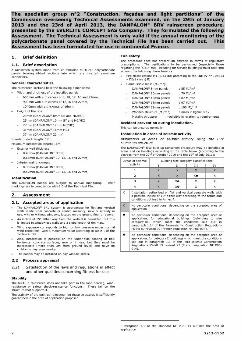
Installation in areas of seismic activity
Installation in areas of seismic activity using the BRV aluminum structure
The DANPALON® BRV built-up rainscreen procedure may be installed in
areas and on buildings according to the table below (according to the
decrees from the 22nd of October 2010 and the 19th of July 2011):
Areas of seismic
activity
Building size category classifications
I II III IV
1 X X X X
2 X X X X
3 X X X X
4 X X X X
X Installation authorized on flat and vertical concrete walls with a possible incline of 15° either way according to the terms and
conditions outlined in Annex A
X No particular conditions, depending on the accepted area of
application
No particular conditions, depending on the accepted area of
application, for educational buildings (belonging to size
category III) which meet the conditions laid out in
paragraph 1.11 of the Para-seismic Construction Regulations
PS-MI 89 revised 92 (French regulation NF P06-014),
No particular conditions, depending on the accepted area of
application, for category II buildings which meet the conditions
laid out in paragraph 1.1 of the Para-seismic Construction
Regulations PS-MI 89 revised 92 (French regulation NF P06-
014).
1 Paragraph 1.1 of the standard NF P06-014 outlines the area of
application
2/13-1552 3
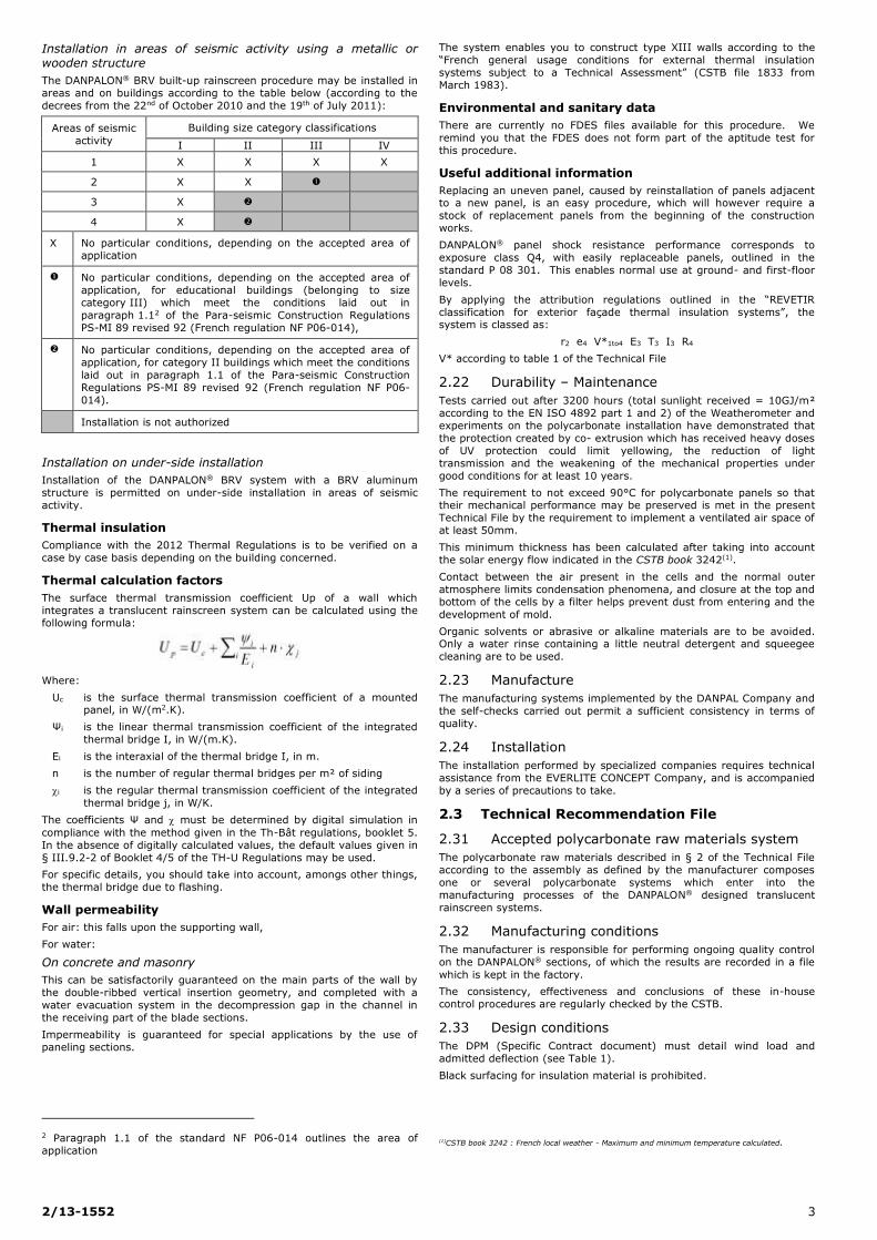
Installation in areas of seismic activity using a metallic or wooden structure
The DANPALON® BRV built-up rainscreen procedure may be installed in
areas and on buildings according to the table below (according to the
decrees from the 22nd of October 2010 and the 19th of July 2011):
Areas of seismic
activity
Building size category classifications
I II III IV
1 X X X X
2 X X
3 X
4 X
X No particular conditions, depending on the accepted area of application
No particular conditions, depending on the accepted area of
application, for educational buildings (belonging to size
category III) which meet the conditions laid out in
paragraph 1.12 of the Para-seismic Construction Regulations
PS-MI 89 revised 92 (French regulation NF P06-014),
No particular conditions, depending on the accepted area of
application, for category II buildings which meet the conditions
laid out in paragraph 1.1 of the Para-seismic Construction
Regulations PS-MI 89 revised 92 (French regulation NF P06-
014).
Installation is not authorized
Installation on under-side installation
Installation of the DANPALON® BRV system with a BRV aluminum
structure is permitted on under-side installation in areas of seismic
activity.
Thermal insulation
Compliance with the 2012 Thermal Regulations is to be verified on a
case by case basis depending on the building concerned.
Thermal calculation factors
The surface thermal transmission coefficient Up of a wall which
integrates a translucent rainscreen system can be calculated using the
following formula:
Where:
Uc is the surface thermal transmission coefficient of a mounted panel, in W/(m2.K).
Ψi is the linear thermal transmission coefficient of the integrated
thermal bridge I, in W/(m.K).
Ei is the interaxial of the thermal bridge I, in m.
n is the number of regular thermal bridges per m² of siding
i is the regular thermal transmission coefficient of the integrated
thermal bridge j, in W/K.
The coefficients Ψ and must be determined by digital simulation in
compliance with the method given in the Th-Bât regulations, booklet 5.
In the absence of digitally calculated values, the default values given in
§ III.9.2-2 of Booklet 4/5 of the TH-U Regulations may be used.
For specific details, you should take into account, amongs other things,
the thermal bridge due to flashing.
Wall permeability
For air: this falls upon the supporting wall,
For water:
On concrete and masonry
This can be satisfactorily guaranteed on the main parts of the wall by
the double-ribbed vertical insertion geometry, and completed with a
water evacuation system in the decompression gap in the channel in
the receiving part of the blade sections.
Impermeability is guaranteed for special applications by the use of
paneling sections.
2 Paragraph 1.1 of the standard NF P06-014 outlines the area of
application
The system enables you to construct type XIII walls according to the
“French general usage conditions for external thermal insulation
systems subject to a Technical Assessment” (CSTB file 1833 from
March 1983).
Environmental and sanitary data
There are currently no FDES files available for this procedure. We
remind you that the FDES does not form part of the aptitude test for
this procedure.
Useful additional information
Replacing an uneven panel, caused by reinstallation of panels adjacent to a new panel, is an easy procedure, which will however require a
stock of replacement panels from the beginning of the construction
works.
DANPALON® panel shock resistance performance corresponds to
exposure class Q4, with easily replaceable panels, outlined in the
standard P 08 301. This enables normal use at ground- and first-floor
levels.
By applying the attribution regulations outlined in the “REVETIR
classification for exterior façade thermal insulation systems”, the system is classed as:
r2 e4 V*1to4 E3 T3 I3 R4
V* according to table 1 of the Technical File
2.22 Durability – Maintenance
Tests carried out after 3200 hours (total sunlight received = 10GJ/m²
according to the EN ISO 4892 part 1 and 2) of the Weatherometer and
experiments on the polycarbonate installation have demonstrated that
the protection created by co- extrusion which has received heavy doses
of UV protection could limit yellowing, the reduction of light
transmission and the weakening of the mechanical properties under
good conditions for at least 10 years.
The requirement to not exceed 90°C for polycarbonate panels so that their mechanical performance may be preserved is met in the present
Technical File by the requirement to implement a ventilated air space of
at least 50mm.
This minimum thickness has been calculated after taking into account
the solar energy flow indicated in the CSTB book 3242(1).
Contact between the air present in the cells and the normal outer
atmosphere limits condensation phenomena, and closure at the top and
bottom of the cells by a filter helps prevent dust from entering and the
development of mold.
Organic solvents or abrasive or alkaline materials are to be avoided. Only a water rinse containing a little neutral detergent and squeegee
cleaning are to be used.
2.23 Manufacture
The manufacturing systems implemented by the DANPAL Company and
the self-checks carried out permit a sufficient consistency in terms of
quality.
2.24 Installation
The installation performed by specialized companies requires technical
assistance from the EVERLITE CONCEPT Company, and is accompanied
by a series of precautions to take.
2.3 Technical Recommendation File
2.31 Accepted polycarbonate raw materials system
The polycarbonate raw materials described in § 2 of the Technical File
according to the assembly as defined by the manufacturer composes
one or several polycarbonate systems which enter into the
manufacturing processes of the DANPALON® designed translucent
rainscreen systems.
2.32 Manufacturing conditions
The manufacturer is responsible for performing ongoing quality control
on the DANPALON® sections, of which the results are recorded in a file
which is kept in the factory.
The consistency, effectiveness and conclusions of these in-house
control procedures are regularly checked by the CSTB.
2.33 Design conditions
The DPM (Specific Contract document) must detail wind load and
admitted deflection (see Table 1).
Black surfacing for insulation material is prohibited.
(1)CSTB book 3242 : French local weather - Maximum and minimum temperature calculated.

4 2/13-1552
Fixings
When choosing the fixings used to attach the system to the supporting
structure, you must take into account the wind exposure conditions and
their rupture calculation resistance value applied to the chosen surface.
If using a concrete support packed with granulate or masonry, the
ultimate anchor resistance limit will be calculated according to the ATE
(or if necessary according to the Technical Assessment in the case of
certain chemic masonry seals).
In the event that you do not know the surface’s characteristics, the ultimate anchor resistance limit will be verified by a prior study, in
compliance with the document “On-site determination of the ultimate
resistance limit of a mechanical fixation for rainscreen”
(CSTB books 1661-V2)(1).
Aluminum structure
The aluminum structure will be designed to be freely expandable, in
compliance with the instructions in the document “General regulations
for the design and installation of the metallic structure and thermal
insulation for built-up rainscreen subject to a Technical Assessment”
(CSTB books 3194 and 3586-V2)(2), plus the following:
The coplanar nature of the upright supports must be verified
between adjacent sections, with a maximum permissible gap of
2mm.
The permissible resistance for the relevant vertical load-bearing
mounting brackets corresponds to a load deformation equal to
3mm.
The interaxial between uprights must be 600, 900 or 1040mm
maximum.
The structure, for each site, must be subject to a design report,
established by the installer company, assisted, if necessary, by the EVERLIGHT CONCEPT Company.
Wooden structure
The design and installation of the wooden structure must comply with
the instructions in the document “General regulations for the design
and installation of the wooden structure and thermal insulation for
built-up rainscreen subject to a Technical Assessment” (CSTB book
3316-V2)(3), plus the following:
The coplanar nature of the rafters must be verified between
adjacent sections, with a maximum permissible gap of 2mm.
Wooden rafters with a mechanical resistance corresponding to at
least C19 class according to the standard EN 338, with natural or enhanced durability of usage class 2 according to the FD P 20-651.
At the time of their installation, the wooden rafters and lintels must
have a maximal target humidity of 18%, with a discrepancy
between two components no greater than 4%. The water content
of the components must be calculated according to the method laid
out by the standard EN 13183-2 (with a recent moisture meter).
The flat angle brackets for the fixings must be subject to tests
which take into account a load deformation of no more than 3mm.
The rafter interaxial may be no larger than 600 mm.
2.34 Installation conditions
Layout
The EVERLITE CONCEPT Company will provide to the installer, following
a written request, their technical assistance during the preliminary study and the installation of the structure.
Storage
On site, the piles of stocked DANPALON® panels, even when kept in
their packaging, must be protected from direct exposure to sunlight.
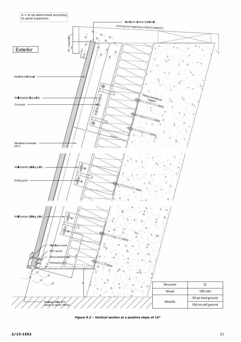
Bottom profile drainage
The bottom profiles are to be drilled on site, or maybe ordered pre-
drilled. The installation company will check that the drainage holes (Ø
10 / 150mm) have been correctly drilled.
Direct installation onto the support
As the structure is fixed directly onto the support, planar defects of this
support (differences in level, bricks jutting out, bumps and other
irregularities) must not exceed 5mm under a 20cm rule, and 10mm
under a 2m rule.
This flatness must be taken into account in the DPM.
Installation in areas of seismic activity
To install DANPALON® panels on a BRV structure, the areas of seismic
activity and the buildings’ size categories require justification. The
specific conditions for installation are laid out in Annex A at the end of
the file.
Conclusions
Overall appraisal:
The use of the DANPALON® BRV procedure in the accepted area of
application has been favorably appraised.
Validity:
Until the 30th of April 2016.
For the Specialist Group n°2 The President
D. ROYER
3. Additional comments from the
Specialist Group
The polycarbonate panels installed as built-up ventilated rainscreen
constitute a new category.
No films or membranes may be fixed to the insulation, in order to avoid
any blockage of the air gap.
For satisfactory panel durability in the context of their use in built-up
rainscreen, an air space of at least 50mm on their rear surface is
required.
Given the elasticity of the polycarbonate panels and their attachment to
the connectors, they do not need to be recut when you divide up the
structure pieces.
Although they do expand, the panels may slide one over the other when they are fitted into the same connector, and this permits the use
of single sections along the vertical siding of bay windows which can
hold one side of the panel running across it and the other of those
located flush and on the lintel.
The width of the windows is a multiple of the width of the panels.
This Technical Assessment is subject to annual monitoring of the
DANPALON® panels.
The Cladding Reporter attached to Specialist Group n°2
M. SOULE
(1)French document which explains how to estimate by test in site the mechanical properties of a
fixing rawl plugs.
(2)CSTB book 3194 and 3586-V2 French general installation guide for metallic structure and external insulation for buildings.
(3)CSTB book 3316-V2, French general installation guide for wood structure and external insulation for buildings.

2/13-1552 5
Technical File created by the applicant
A. Description
1. Principle
Ventilated rainscreen system composed of double, triple, quadruple or
sextuple layers panels, extruded using MAKROLON ET 3227
polycarbonate from the BAYER Company.
The DANPALON® panels are available in:
600mm for thicknesses 8, 10, 12, 16 and 22mm,
900mm for thicknesses 12,16 and 22mm,
1040mm for 16mm thicknesses.
They bear raised seam sections (double seam) upon which are inserted
aluminum connectors.
The accessories associated with the system include the components for attaching it to structures made of concrete, wood, steel or aluminum.
Additional insulation is, most often, used between the main building
and the rainscreen. This insulation is ventilated by an air gap between
the insulation and the rear of the DANPALON® BRV.
2. Materials
2.1 DANPALON® panels
The panels, connectors and accessories of the DANPALON® BRV system
are extruded using MAKROLON ET 3227 polycarbonate from the BAYER
Company, and the characteristics are briefly listed in the table below:
Quality Testing
method Unit Value
Density ISO R 483 g/m3 1.2
Traction resistance
at 23°C ISO 527 N/mm2 65-70
Stretching at 23°C ISO 527 % 80-120
Elasticity module ISO 6721-1 N/mm² > 2300
Expansion coefficient ISO 179 M/m°C 70. x 10-6
UV protection (Benzotriasol Dimmery) provided by co-extrusion at a
thickness of 45 microns on the outer surface protects the panels from
photo-oxidation and ultra-violet solar radiation.
The cells are closed off using a micro-perforated aluminate tape.
2.2 Structure and fixings
Primary framework:
- EN AW 6060 T5 aluminum alloy in accordance to EN 755-2 for
connectors, profiles, corner sections and mounting brackets.
- Wooden rafters with a mechanical resistance corresponding at
least to class C18 according to the standard EN 338, natural or
enhanced durability of usage class 2 according to the FD P 20-
651.
Fixings:
- Aluminum alloy for the body and at least A2 stainless steel for
the fixing rivet rods for the mounting brackets in the BRV connectors.
- At least A2 austenitic stainless steel for the self-drilling screws
and well as for the fixing screws for the connectors used in the
primary wooden or metallic structure.
2.3 Accessories
Pre-lacquered aluminum sheets in accordance to the standard EN
1396 or pre-lacquered sheet steel in compliance with the French
standard P 34-301 for conception of different flashings, with an
exposure classification in compliance with the French standard P
24-351.
ACERMI-certified insulation panels in accordance to CSTB book
3586-V2.(1) and 3316-V2(2) (1) CSTB book 3586-V2 French general installation guide for metallic structure and external insulation for buildings.
(2) CSTB book 3316-V2, French general installation guide for timber structure and external insulation for buildings.
3. Components
The DANPALON® BRV system is a complete rainscreen system, including:
3.1 DANPALON® Panels
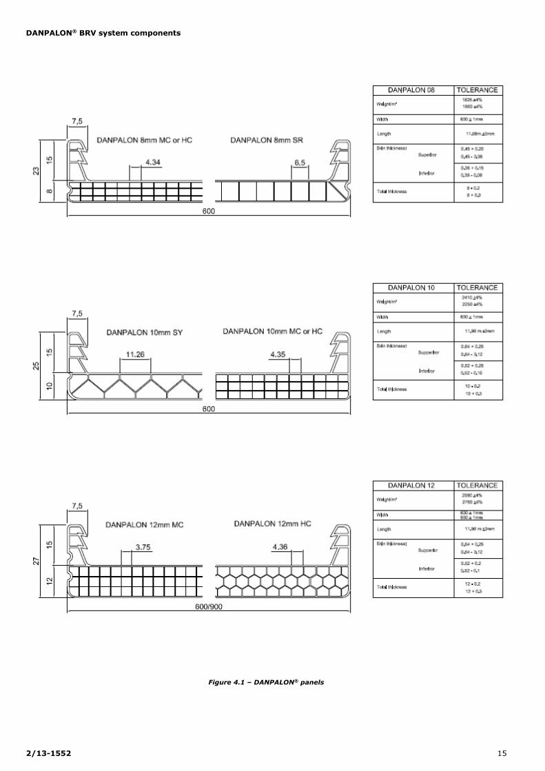
The panels are available in 8, 10, 12, 16 and 22mm thicknesses
(see fig. 4).
The 8mm DANPALON® SR panels are double-layers with rectangular
cells.
The full height of the lateral raised ribs is 23mm.
The 8mm DANPALON® MC/HC panels are quadruple-layers, with
rectangular or hexagonal cells.
The full height of the lateral raised ribs is 23mm.
The 10mm DANPALON® SY panels are triple-layers with a triangular
structure. The full height of the lateral raised ribs is 25mm.
The 10mm DANPALON® MC/HC panels are quadruple-layers, with
rectangular or hexagonal cells.
The full height of the lateral raised ribs is 25mm.
The 12mm DANPALON® MC/HC panels are quadruple-layers, with a
rectangular or hexagonal structure.
The full height of the lateral raised ribs is 27mm.
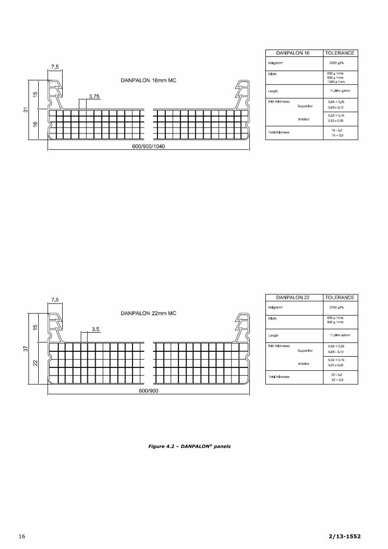
The 16mm DANPALON® MC panels are six-layers, with rectangular
cells. The full height of the lateral raised ribs is 31mm.
The 22mm DANPALON® MC panels are six-layers, with a rectangular
structure.
The full height of the lateral raised ribs is 37mm.
Abbreviations:
MC: Multi-cellular
HC: Hexagonal (honeycomb)
SY: Y structure.
3.11 Dimensional characteristics
Width 600mm (tolerance ± 1mm) in thicknesses 8, 10, 12, 16 and
22mm;
Width 900mm (tolerance ± 1mm) in 12, 16 and 22mm thicknesses;
Width 1040mm (tolerance ± 1mm) in 16mm thickness;
Length: adapted to the project with a standard length of 11.98m
(tolerance ± 3mm) and upon special request for longer than this (with
the maximum length determined by the transport constraints, in this
case consult EVERLITE CONCEPT). The lengths of the panels to be
installed is limited to 16m.
Thickness: full section 8, 10, 12, 16 and 22mm.
Other specific dimensions are listed in figure 4.
3.12 Area densities
DANPALON® Panels
Thickness Type Panel only
08 mm SR 1 660 g/m²
08 mm MC/HC 1 826 g/m²
10 mm SY 2 250 g/m²
MC/HC 2 416 g/m²
12mm MC/HC 2 585 g/m²
16 mm MC 3 300 g/m²
22 mm MC 3 700 g/m²
(Manufacture tolerance – 0; + 4%)
3.13 Color schemes and finishes
The standard colors are Crystal (colorless) and Ice (translucent white).
6 2/13-1552
Upon request, panels may be delivered in other color schemes: Blue,
Green, Opal, Bronze, Alu-Gray, Yellow, Red, Orange, Mauve, Gray,
Gold… A tonal difference in the visual appearance of the colors of
panels originating from the same production that does not jeopardize
the mechanical characteristics of the polycarbonate components is
accepted and is inherent to the extrusion manufacturing constraints.
Certain further surface treatments, most notably SOFTLITE (anti-glare),
HP (High Protection) or Irisé (Chameleon) may affect the colors of the range of panels.
3.14 Chemical substance resistance
The chemical resistance of polycarbonate is detailed in the table below:
Chemical agent Resistance
Dilute acids Good
Concentrated acids Medium to good
Alkalis Poor to medium
Organic solvents – alcohol Good
Chlorinated hydrocarbons Poor
Aromatic hydrocarbons Poor
Aliphatic hydrocarbons Poor
Lubricating oils Good
Detergents Good
3.2 Structure
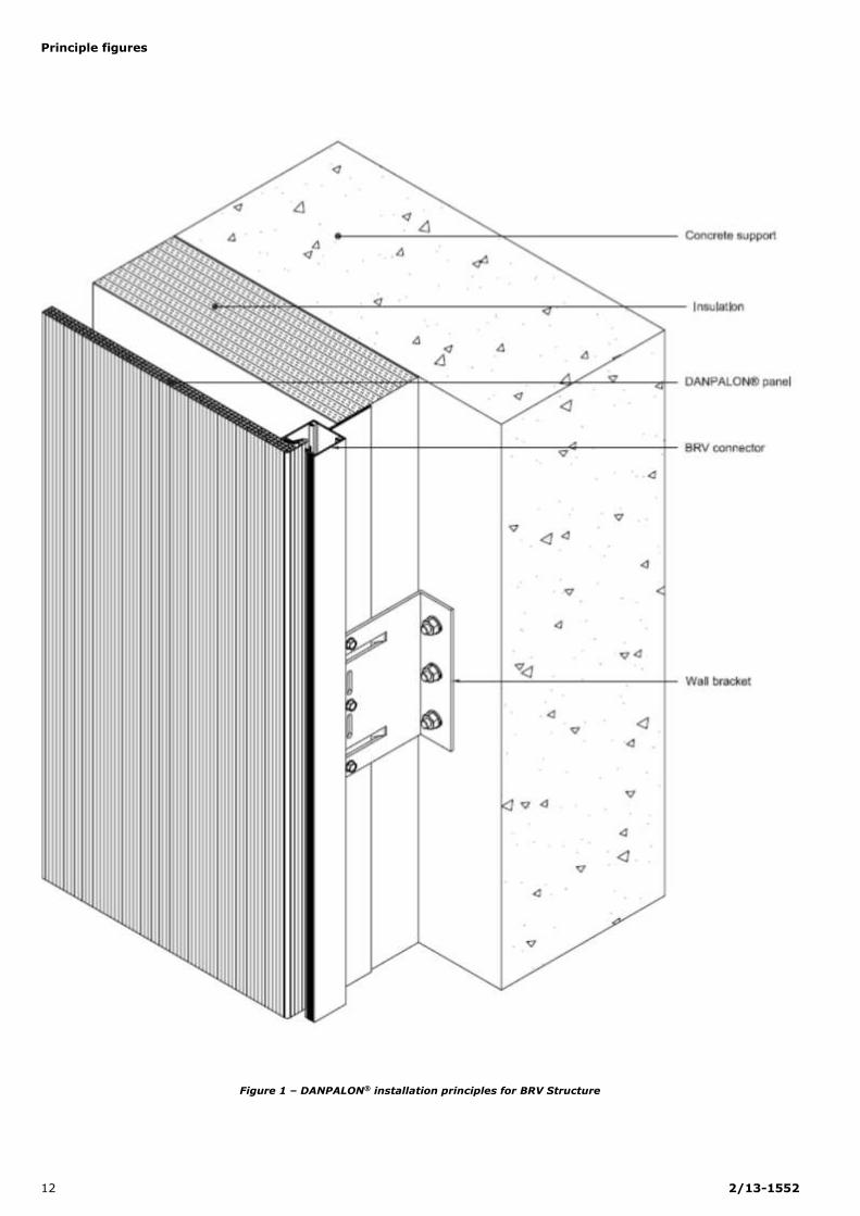
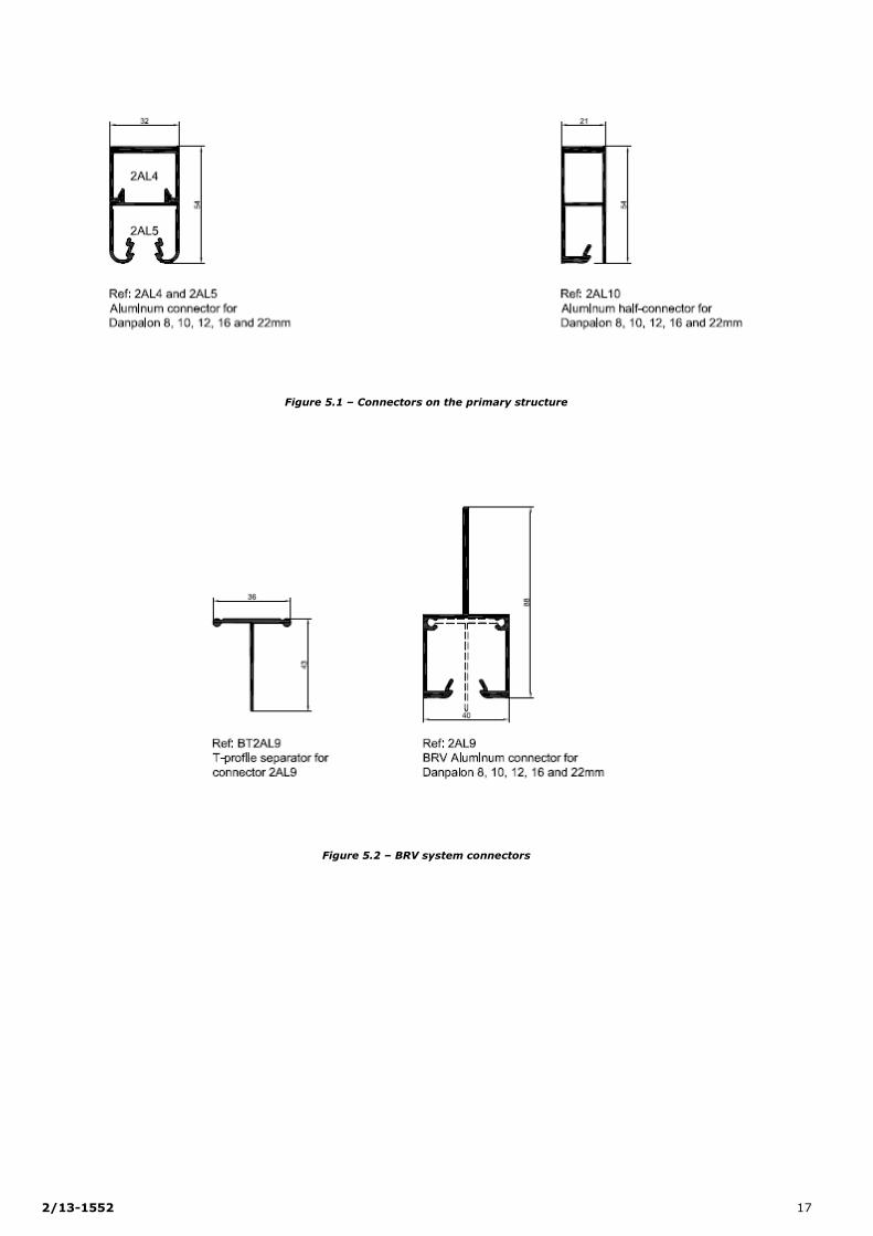
3.21 BRV System (see fig. 1)
BRV Aluminum connector (see fig. 5)
Made from mill finish or anodized extruded aluminum (according to the
French standard P 24-351):
Type 2AL7: BRV connector in mill finish extruded aluminum, 32mm
wide by 79mm high,
Type 2AL9: BRV connector in mill finish extruded aluminum, 40mm
wide by 88mm high. This lets you add, if necessary, a T-
component in extruded aluminum. This T acts as a spacer and
allows you to slide two DANPALON® panels independently of each
other.
These connectors constitute the primary system framework. They have
a maximum length of 6m and are of a freely expandable design.
Mounting brackets
The mounting brackets are in EN AW 6060 TG aluminum alloy in
accordance to EN 755-2.
The fixing brackets must be in compliance with the CSTB books 3194
and 3586-V2, and must be subject to tests which take into
consideration a vertical load deformation of no more than 3mm.
The depths of the mounting brackets is to be determined according to
the thickness of the insulation and the thickness of the air space.
The mounting brackets are installed with a maximum interaxial of
1.4m.
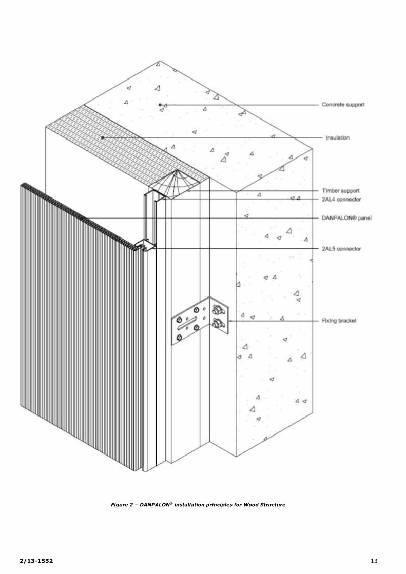
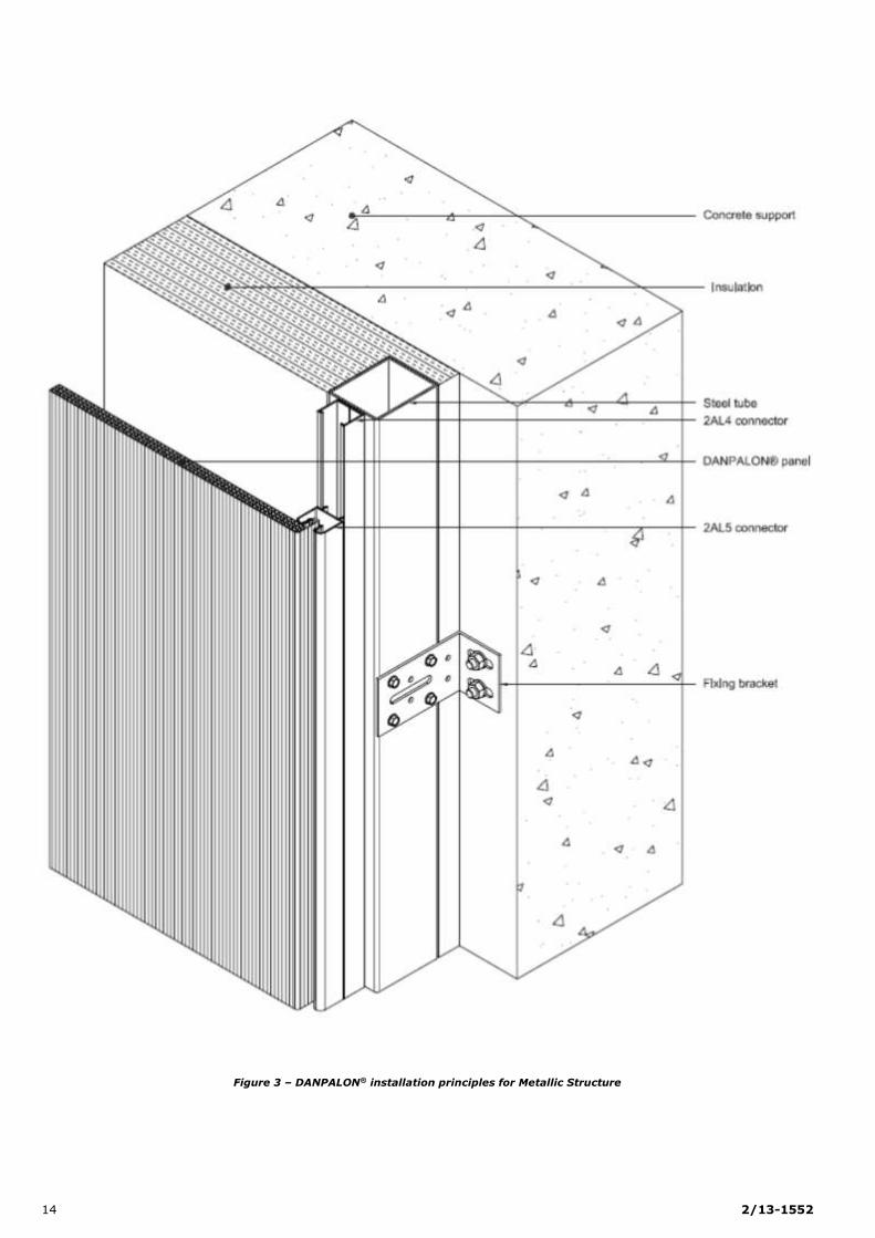
3.22 Primary structure system (see fig. 2 and 3)
Aluminum connector (see fig. 5)
Made from mill finish, anodized or lacquered extruded aluminum
(according to the French standard P 24-351):
Type 2AL4 / 2AL5: two part clip connectors in mill finish, anodized
or lacquered extruded aluminum at 32mm wide by 54mm high.
Type 2AL10: half-connector in anodized or lacquered extruded
aluminum, 21mm wide by 54mm high.
Aluminum structure
An aluminum structure in compliance with the “General regulations for
installing structures and thermal insulation for built-up rainscreen
subject to a Technical Assessment” (CSTB books 3194 and 3586-V2)(1).
The aluminum structure is of a freely expandable design. It is
considered to be a protected and ventilated atmosphere.
The lengths of the upright supports are to be no greater than 6m.
The face widths of the upright supports are to be at least 40mm.
The interaxial between upright supports is 600, 900 or 1040mm maximum.
Wooden structure
A framework consisting of wooden rafters and insulation in compliance
with the “General regulations for the installation of wooden structures
and thermal insulation for built-up rainscreen subject to a Technical
Assessment” (CSTB Book 3316-V2)(2).
The rafters must have the following minimum dimensions:
A face width of 40mm,
A minimum depth of 40mm (30mm min. if installing directly onto
the surface).
The interaxial between rafters is 600mm maximum.
Installation with adjustable brackets
The rafters are fixed using a stainless or galvanized steel sleeper bolt.
This fixing is completed 2 wood screws.
Installation directly onto the building surface
The rafters may be fixed directly onto the building’s surface.
3.3 Fixings
3.31 BRV aluminum connectors (see fig. 7)
The BRV connectors and the mounting brackets are fixed using:
Alu-Stainless steel rivets, reference CL14, the rivet body in
aluminum Al Mg Ø 5mm, the mandrel in A2 stainless steel, the collar is to be Ø 14mm and the tightening thickness must be a
maximum of 8mm.
The characteristics according to the standard XP P30-310 (on an
aluminum support with a minimum thickness of 18/10thmm):
PK shearing = 230.7 daN
5.5 x 25mm screws – PERFIX TH/A2, in A2 stainless steel on a
support with a minimum thickness of 25/10th mm
The characteristics according to the standard NF P30-310
PK shearing = 720 daN
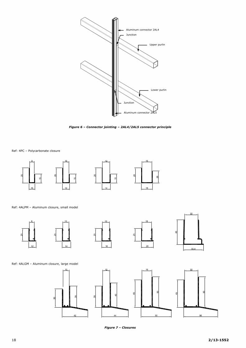
3.32 Aluminum connectors on the primary structure
The 2AL4/2AL5 aluminum connectors are fixed using two self-drilling
screws with a diameter of 6.3mm (length and type adapted to the surface) on each support. A guideline has been added to the 2AL4
profile (low connector base profile) to help you with this.
3.4 Associated accessories
3.41 Panel seals (see fig. 8)
These are used to block the ends of the panels with a micro-perforated anti-dust adhesive tape, with the aim of minimizing dust entry into the
cells.
They are manufactured:
In polycarbonate, code 4PC in Crystal color for DANPALON® 8, 10,
12, 16 and 22mm,
In aluminum, codes 4AL PM, 4AL GM (AGS 6060 T5 alloy), mill
finish, lacquered or anodized aluminum for DANPALON® 10, 12, 16
and 22mm.
For applications where the ends will be concealed, the DANPALON® may also be fitted solely with a micro-perforated anti-dust adhesive tape
across the open ends.
3.42 Micro-perforated aluminate adhesive tape
A micro-perforated aluminate adhesive tape with a width of 24mm for
8, 10 and 12mm thick panels, 38mm for 16mm thick panels and 50mm
for 22mm panels (33m rolls).
The adhesive is to be placed on each upper and lower end of the
panels, and also on any cut surface. As an optional extra, it can be
delivered already installed on the panels by EVERLITE CONCEPT.
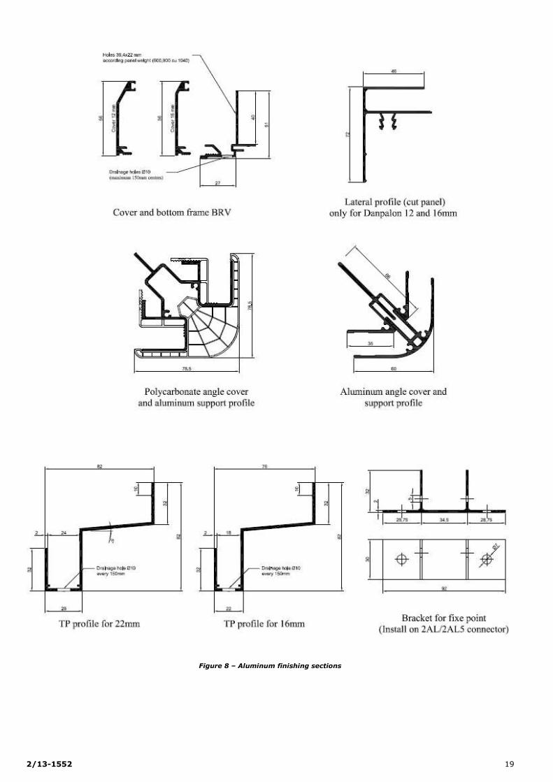
3.43 Aluminum finishing profiles
TP profile (see fig. 6)
The TP profile is made from mill finish or anodized extruded aluminum
for 16mm and 22mm DANPALON® panels. On the lower part, drainage
and ventilation holes at ø 10mm have been drilled with center to center
of 150mm.
BRV profile (see fig. 6)
The BRV profile is made from different components composed of extruded, anodized or powder coated aluminum. It is used with
DANPALON® rainscreen Systems with thicknesses of 10, 12 and 16mm
and include:
The support section,
The lower edge holder,
On the lower part, drainage and ventilation holes at Ø 10mm have been
drilled with center to center of 150mm.
(1)CSTB book 3194 and 3586-V2 French general installation guide for metallic structure and external insulation for buildings
(2)CSTB book 3316-V2, French general installation guide for timber structure and external insulation for buildings.

2/13-1552 7
3.44 Brace (see fig. 9)
Made from mill finish or lacquered aluminum (according to the French
standard P 24-351) or stainless steel, it is directly fixed to the lower
point of the aluminum connector using a M6x50 bolt.
This acts as a fixed point (buttress) for the DANPALON® panel and the
ventilation mesh support.
4. Manufacture
The DANPALON® panels are extruded by the DAN PAL company under
ISO 9001 certification in their DAN factory in Israel.
Manufacture is a continuous process and includes the following
operations:
Delivery and storage of the raw material in the form of bags of
granules,
Extrusion,
Any necessary coating,
Co-extrusion on the outer surface (and/or the inner surface,
optional for special requests),
Cooling in the forming machine,
Coating with a protective film on both sides to prevent scratches
during handling,
Lengthwise cutting and shipping/packaging.
5. Manufacture checks and tests
Raw material checks
The raw material, supplied in its original packaging by the BAYER
Company, has been awarded the ISO 9001 certificate, and is subject to
checks upon delivery to the factory.
Each batch is awarded a quality certificate. Also, the following
characteristics are checked:
Resin code Characteristics
Raw material Density
MAKROLON ET 3227 Bayer MFR, LT
UVA 67890 protective layer, Kafrit
Density UV protection
Mid-manufacture and finished product checks and tests
The principle manufacturing self-testing operations are the following:
Extrusion process speed checks,
Samples are taken of the sections every 2 hours,
The samples are subject to visual inspection and measurements to
determine mass, side thickness, panel width and parallelism. The
measurements are taken across different parts of the panel and are
recorded in a register:
Dimension and weight characteristics are checked at least once per
station,
Flatness, transparency, shine for each panel (visual),
Thickness checks on the UV-protection layer at the start of each
manufacturing process and at least once per station.
Insertion test with the U connector at the joint between two panels:
the size is checked using a connector insertion test (polycarbonate
or aluminum) on the DANPALON® panels,
Hard object impact resistance tests,
Thickness checks for the UV-protection layer on the outer surface of
the DANPALON® rainscreen.
6. Identification
DANPALON® panels are subject to CSTB monitoring. They are
identifiable every 50cm by an engraving or a label anchored directly
onto one of the lateral returns, and these include:
The date of manufacture in digits,
The DANPALON® logo,
The UV-protection direction (double chevrons, the points of which
show in which direction the UV protection is oriented).
7. Supplies – Technical Assistance
The EVERLITE CONCEPT Company does not install the panels; they
distribute and deliver DANPALON® panels, the aluminum connectors
and the extruded finishing components for the DANPALON® BRV system
to installer companies.
All other components are directly sourced by the installer, in
compliance with the instructions and conditions in the present Technical
File.
The EVERLITE CONCEPT Company has a technical advice department
and may provide, upon request by the installer, technical assistance
both in terms of project deign and during installation.
8. Area of application
Installation on flat and vertical walls, brand new or in use, on
masonry or concrete located on the ground floor and above.
An incline of 15° either side of the vertical is permitted, but only for
walls without windows and at a slope length of no more than 6m (see fig. 9.2).
Wind exposure corresponds to high or low pressure under normal
wind conditions, with a maximum value according to table 1 of the
Technical File.
Also, installation is possible on soffit, horizontal concrete surfaces,
brand new or in use, but they must be inaccessible (more than 3 m
from ground level) and have no children’s play area nearby.
The panels may be installed on bay window lintels.
The DANPALON BRV® rainscreen system is permitted in areas of
seismic activity.
The instructions to follow for areas of seismic activity are laid out in
Annex A for installation on a metallic structure in the Technical File.
9. Structure and thermal insulation
installation
Thermal insulation
The insulation is installed in compliance with the instructions in the
following documents:
For installation on a wooden structure: “General regulations for the design and installation of the wooden structure and thermal
insulation for built-up rainscreen subject to a Technical Assessment”
(CSTB book 3316-V2 (1)).
For installation on a metallic structure: “General regulations for the
design and installation of the metallic structure and thermal
insulation for built-up rainscreen subject to a Technical Assessment”
(CSTB books 3194 and 3586-V2 (2)).
Metallic structure
The installation of the metallic structure must be in compliance with the
instructions in the CSTB books 3194 and 3586- V2 (2), with the addition
of the following:
The coplanar nature of the upright supports must be verified
between adjacent sections, with a maximum permissible gap of
2mm.
The permissible resistance for the relevant vertical load-bearing
mounting brackets corresponds to a load deformation equal to
3mm.
The interaxial between uprights must be 1040mm maximum.
Wooden structure
The installation of the wooden structure must be in compliance with the
instructions in the CSTB books 3316- V2 (1), with the addition of the
following:
The coplanar nature of the rafters must be verified between
adjacent sections, with a maximum permissible gap of 2mm.
Wooden rafters with a mechanical resistance corresponding to at
least C19 class according to the standard EN 338, with natural or
enhanced durability of usage class 2 according to the FD P 20-651.
At the time of their installation, the wooden rafters and lintels must
have a maximal target humidity of 18%, with a discrepancy
between two components no greater than 4%. The water content
of the components must be calculated according to the method laid out by the standard EN 13183-2 (with a recent moisture meter).
The permissible vertical load-bearing resistance for the bracket
concerned must correspond to a load deformation equal to 3mm.
The rafter interaxial may be no larger than 600mm.
(1) CSTB book 3316-V2, French general installation guide for timber structure and external insulation for buildings
(2).CSTB book 3194 and 3586-V2 French general installation guide for metallic structure and external insulation for buildings
8 2/13-1552
10. Installation
10.1 General installation principles
The DANPALON® rainscreen components are delivered to the site, cut to
size and are installed upright (“vertically”), or with an incline of 15° either way for transversal purlins, or as a Support Solution.
The lengths of the panels ordered must take into account the size
differences due especially to expansion (the temperature delta to take
into consideration must correspond to the difference in installation
temperature and the maximum temperature permitted for the panels,
90°C) and the space required for installation.
Installation of the DANPALON® rainscreen components must begin in
accordance to the blueprints made by the installer, whether from right
to left or vice versa, whether based on the center of the construction or
from the front.
Given the elasticity of the polycarbonate panels and their fixing to the
connectors, they do not need to be cut when you are dividing up the
structure.
The bay window width is a multiple of the panel width (the aim of this
is not to have any L-shaped panels).
10.2 Installation on a BRV structure
The connectors are progressively installed with a horizontal spacing of:
601mm (-0/+1) for 600mm panels,
901mm (-0/+1) for 900mm panels,
1041mm (-0/+1) for 1040mm panels.
The loads applied are given in table 1.
In the event that your façade is fitted with bay openings, only the 2AL9 aluminum connector with, if necessary, an added T profile is to be used
(the T isn’t mandatory, it is used when a 6m panel comes into contact
with a smaller component).
The DANPALON® panels with micro-perforated aluminate adhesive tape
on the two end pieces are connected progressively using a rubber
mallet and a wooden peg, taking care to install the UV protection side
outwards. It is crucial that the inner face’s protective film is removed
before the panel is installed.
The fixed points are constructed at the bottom of the panel using transversal screws on the 2AL9 connector or with braces on the 2AL7
connector. The protective film on the outward-facing surface must be
removed.
The system is completed with the installation of the panel closures or
low profiles and by the metal sheet paneling (not supplied by EVERLITE
CONCEPT). On the lower part, at the start of the rainscreen and the
bay lintels, drainage and ventilation holes must be drilled with center to
center of 150mm.
NB: It is necessary to install an anti-rodent mesh on the lower part of the rainscreen, over the air ventilation holes.
10.3 Installation on the Primary Structure
The 2AL4 profile (base connector profile) is fixed using two self-drilling screws with a diameter of 6.3mm (length and type adapted to the
support) onto the primary aluminum structure. A guideline is marked
on it to help you.
The fixing density per support is to be verified according to the
installer’s request and the installation’s permissible rupture resistance.
Manually clip the 2AL5 aluminum section (draining connector profile)
onto the 2AL4 aluminum section.
Installation of the panels and finishing components is identical to the
process described above.
10.4 Air space ventilation
An uninterrupted and unrestricted air space must be positioned
between the outer surface of the insulation and the back of the DANPALON® panels.
This air space must be at least 50mm thick.
Air space ventilation is guaranteed by openings at the base and top of
the structure.
Ventilation sections are to be:
250cm² for rainscreen up to and including 5m in height
500cm² for rainscreen between 5m and 16m in height.
At the base of the rainscreen, the opening is protected by a structural
section with a perforated grid which acts as a rodent barrier. At the closure on the topmost section, the opening is protected by flashing
(see fig. 10).
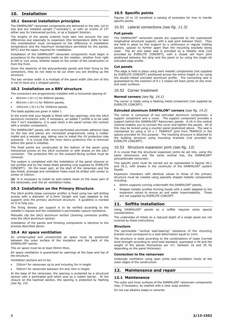
10.5 Specific points
Figures 10 to 19 constitute a catalog of examples for how to handle
specific points.
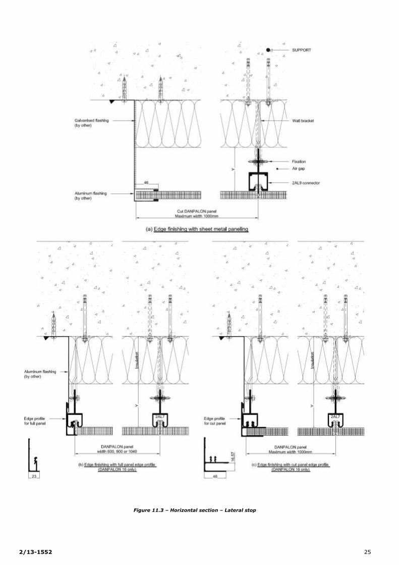
10.51 Lateral connections (see fig. 11.3)
Full panels
The DANPALON® rainscreen panels are supported by the superposed
longitudinal structural support, with a seal joint between them. They
are held in place on this support by a continuous or regular holding
section, spaced no further apart than the mounting brackets being
used. The air and water seal is provided by a metallic strip (not
provided by EVERLITE CONCEPT), with a closed cell foam joint
positioned between the strip and the panel or by using the single-rib
extruded edge profile.
Cut panels
This edge is held in place using bent metallic components (not supplied by EVERLITE CONCEPT) positioned across the entire height or by using
the double-ribbed extruded aluminum profile. The connecting seal is
guaranteed by the insertion of 9 x 3 closed cell foam joints on the inner
and outer surfaces.
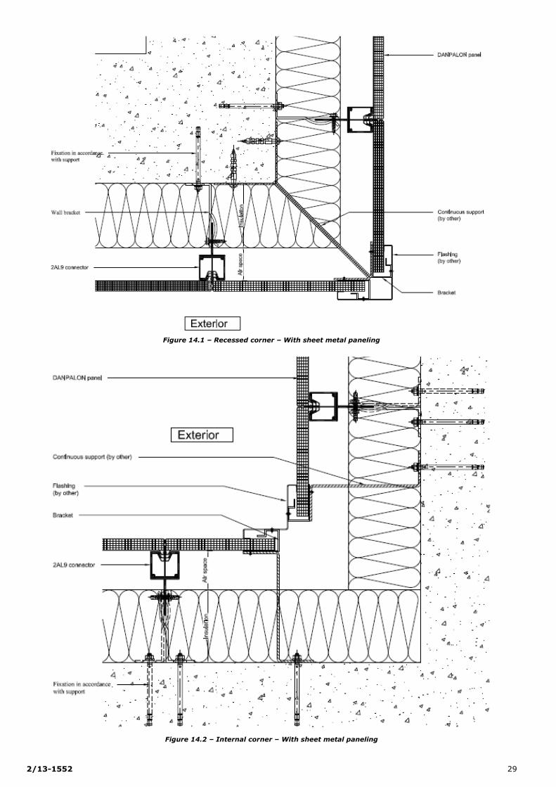
10.52 Corner treatment
Normal corners (see fig. 14.1)
The corner is made using a flashing metal component (not supplied by
EVERLITE CONCEPT).
Extruded aluminum DANPALON® corners (see fig. 14.2)
The corner is composed of two extruded aluminum components: a
support component and a cover. The support component provides a
support behind the DANPALON® Rainscreen panels. A rib in the central
channel enables you to connect the cover and tighten the panels. All of
this may be locked using a counter-panel positioned above. The seal is maintained by using a 10 x 1 TRAMOUT joint from TRAMICO in the
spaces provided for this purpose. The resulting structure is attached to
the building structure using mounting brackets (not provided by
EVERLITE CONCEPT).
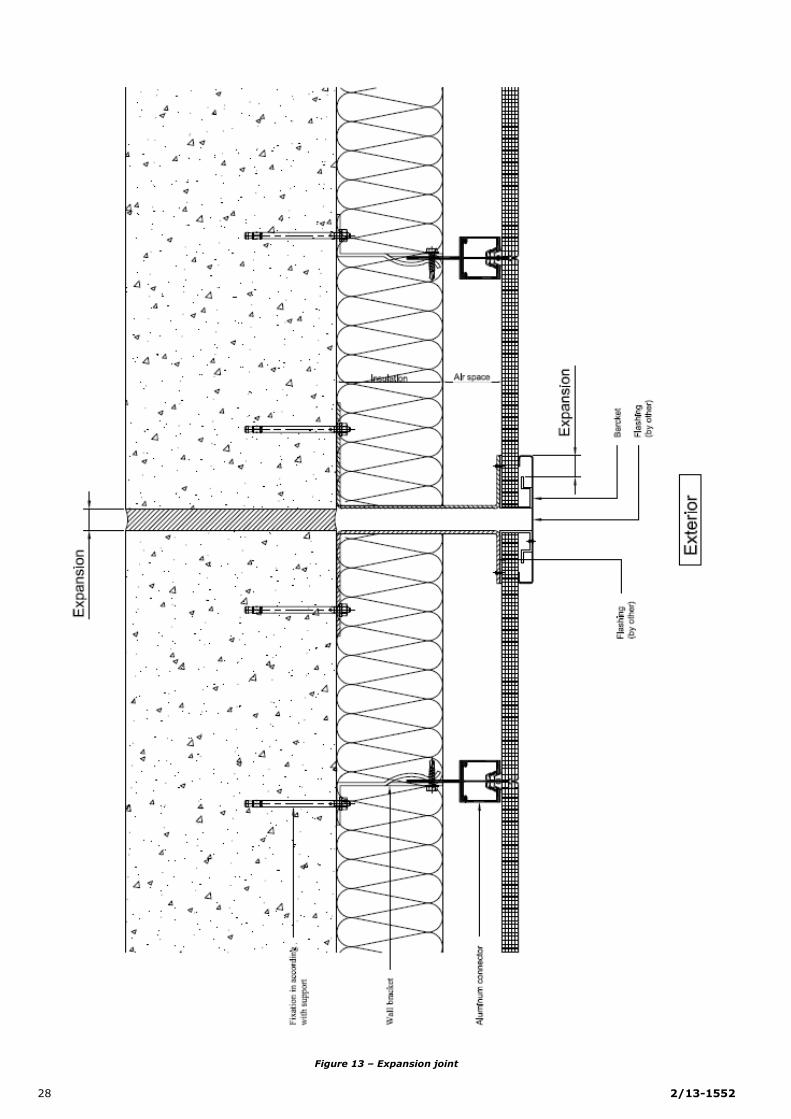
10.53 Structure expansion joint (see fig. 13)
It is crucial that the structural expansion joints be set into, using the
same dimensions and the same vertical line, the DANPALON®
polycarbonate rainscreen.
This specific point must be carried out as represented in figures 26.1
and 26.2, with breaks in the continuity of the DANPALON® system
façade.
Expansion chambers with identical values to those of the primary structure must be created using specially shaped metallic components
including:
60mm supports running underneath the DANPALON® panels,
Shaped metallic profiles forming hoods with a width adapted to the
expansion values to ensure air and water impermeability. These
are not supplied by EVERLITE CONCEPT.
11. Soffite installation
Using DANPALON® panels as a soffite requires some special
considerations.
The undersides of lintels on a reduced depth of a single panel are not
covered by these instructions.
Structure
The permissible “vertical load-bearing” resistance of the mounting
bracket must correspond to a load deformation equal to 1mm.
The structure is sized according to the combinations of loads (normal
wind strength according to wind load standard, expressed in Pa and the
weight of the panels themselves per m², between 16 and 35 Pa
depending on the panel thickness).
Connection to the rainscreen
Underside ventilation using open joints and ventilation tracts at the
outer edges of the construction.
12. Maintenance and repair
12.1 Maintenance
The outer and inner surfaces of the DANPALON® rainscreen components
may, if necessary, by washed with a clear soap solution.
Do not use alkaline soaps or solvents.
2/13-1552 9
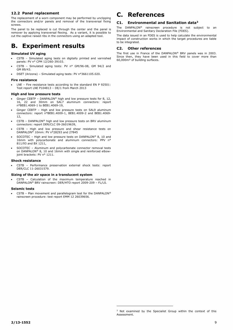
12.2 Panel replacement
The replacement of a worn component may be performed by unclipping
the connectors and/or panels and removal of the transversal fixing
screws.
The panel to be replaced is cut through the center and the panel is
remover by applying transversal flexing. As a variant, it is possible to
cut the captive raised ribs in the connectors using an adapted tool.
B. Experiment results Simulated UV aging
CSTB – Simulated aging tests on digitally printed and varnished panels: PV n° CPM 12/260-39103.
CSTB – Simulated aging tests: PV n° GM/96-08, GM 94/2 and
GM 89/43.
DSET (Arizona) – Simulated aging tests: PV n°3661105.020.
Fire resistance
LNE – Fire resistance tests according to the standard EN P 92501:
Test report LNE P104813 – DE/1 from March 2013
High and low pressure tests
Ginger CEBTP – DANPALON® high and low pressure tests for 8, 12,
16, 22 and 30mm on SAL7 aluminum connectors: report
n°BEB1.4069-1 to BEB1.4069-19,
Ginger CEBTP – High and low pressure tests on SAL9 aluminum connectors: report n°BEB1.4009-1, BEB1.4009-2 and BEB1.4069-
12,
CSTB – DANPALON® high and low pressure tests on BRV aluminum
connectors: report DER/CLC 09-26019639,
CSTB – High and low pressure and shear resistance tests on
DANPALON® 10mm: PV n°28293 and 27845
SOCOTEC – High and low pressure tests on DANPALON® 8, 10 and
16mm with polycarbonate and aluminum connectors: PPV n°
811/93 and BX 1211,
SOCOTEC – Aluminum and polycarbonate connector removal tests on DANPALON® 8, 10 and 16mm with single and reinforced elbow-
joint brackets: PV n° 1211.
Shock resistance
CSTB – Performance preservation external shock tests: report
DER/CLC 11-26031579.
Sizing of the air space in a translucent system
CSTB – Calculation of the maximum temperature reached in
DANPALON® BRV rainscreen: DER/HTO report 2009-209 – FL/LS.
Seismic tests
CSTB – Plan movement and parallelogram test for the DANPALON®
rainscreen procedure: test report EMM 12 26039656.
C. References
C1. Environmental and Sanitation data3
The DANPALON® rainscreen procedure is not subject to an
Environmental and Sanitary Declaration File (FDES).
The data issued in an FDES is used to help calculate the environmental
impact of construction works in which the target procedures are liable
to be integrated.
C2. Other references
The first use in France of the DANPALON® BRV panels was in 2003.
Since then, they have been used in this field to cover more than
60,000m² of building surfaces.
3 Not examined by the Specialist Group within the context of this
Assessment.
10 2/13-1552
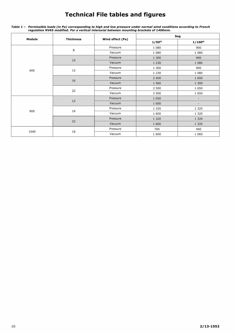
Technical File tables and figures
Table 1 – Permissible loads (in Pa) corresponding to high and low pressure under normal wind conditions according to French
regulation NV65 modified. For a vertical interaxial between mounting brackets of 1400mm.
Module Thickness Wind effect (Pa) Sag
1/50th 1/100th
600
8 Pressure 1 080 900
Vacuum 1 080 1 080
10 Pressure 1 300 900
Vacuum 1 230 1 080
12 Pressure 1 300 900
Vacuum 1 230 1 080
16 Pressure 2 500 1 650
Vacuum 1 560 1 300
22 Pressure 2 500 1 650
Vacuum 2 500 1 650
900
12 Pressure 1 050 -
Vacuum 1 600 -
16 Pressure 1 320 1 320
Vacuum 1 600 1 320
22 Pressure 1 320 1 320
Vacuum 1 600 1 320
1040 16 Pressure 700 460
Vacuum 1 600 1 060
2/13-1552 11
Contents page: figures
Principle figures ....................................................................................................................................................... 12
Figure 1 – DANPALON® installation principles for BRV Structure .................................................................................... 12
Figure 2 – DANPALON® installation principles for Wood Structure .................................................................................. 13
Figure 3 – DANPALON® installation principles for Metallic Structure ................................................................................ 14
DANPALON® BRV system components ...................................................................................................................... 15
Figure 4.1 – DANPALON® panels ................................................................................................................................ 15
Figure 4.2 – DANPALON® panels ................................................................................................................................ 16
Figure 5.1 – Connectors on the primary structure ........................................................................................................ 17
Figure 5.2 – BRV system connectors .......................................................................................................................... 17
Figure 6 – Connector jointing – 2AL4/2AL5 connector principle ..................................................................................... 18
Figure 7 – Closures .................................................................................................................................................. 18
Figure 8 – Aluminum finishing sections....................................................................................................................... 19
Installation details ................................................................................................................................................... 20
Figure 9.1 – Vertical section ...................................................................................................................................... 20
Figure 9.2 – Vertical section at a positive slope of 15° ................................................................................................. 21
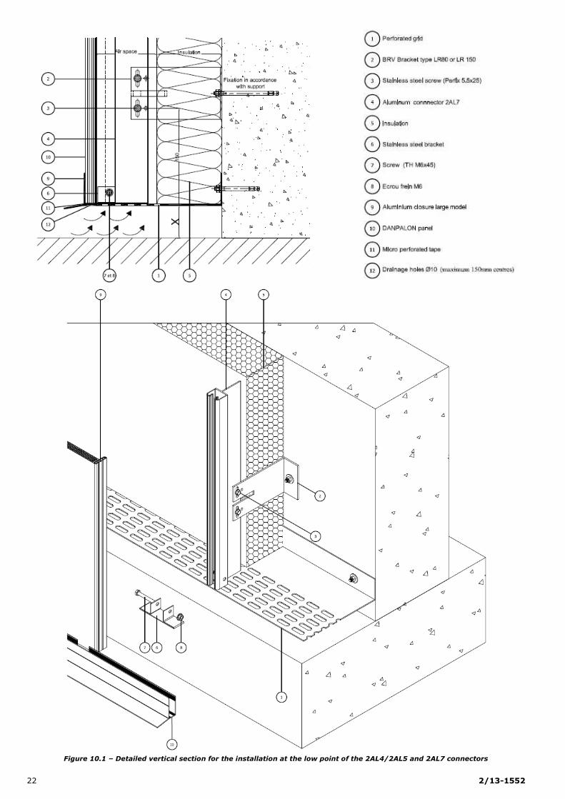
Figure 10.1 – Detailed vertical section for the installation at the low point of the 2AL4/2AL5 and 2AL7 connectors ............... 22
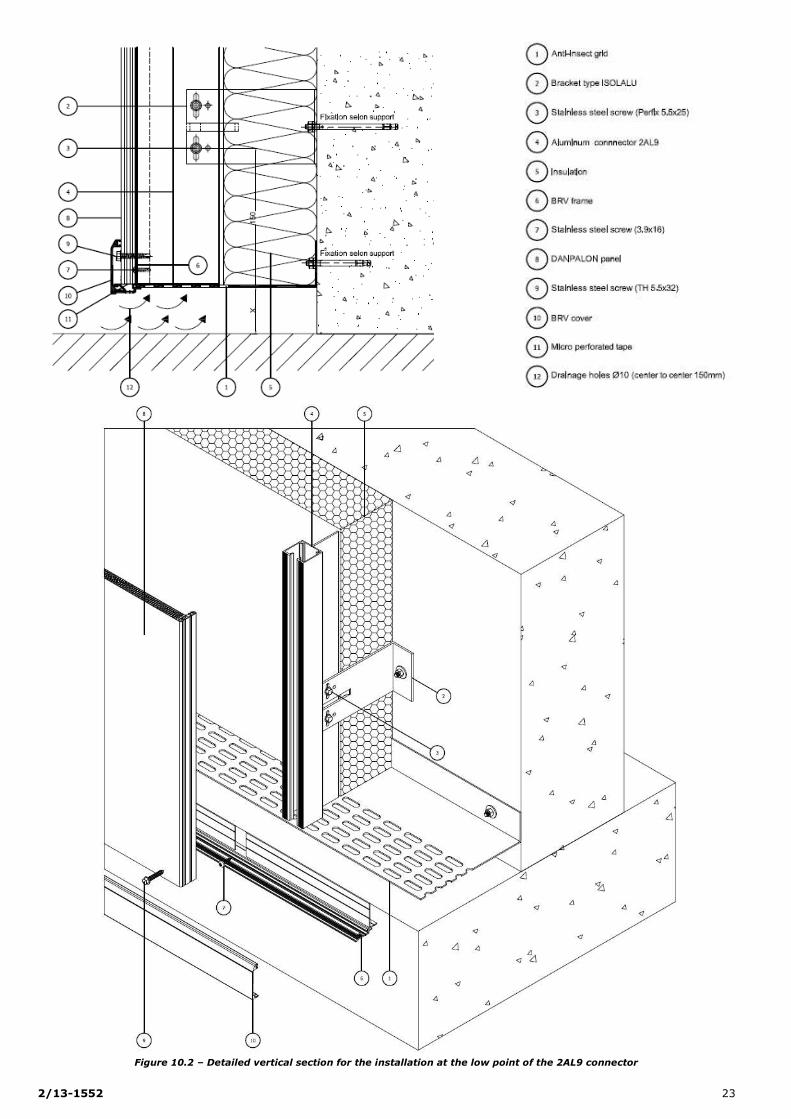
Figure 10.2 – Detailed vertical section for the installation at the low point of the 2AL9 connector ...................................... 23
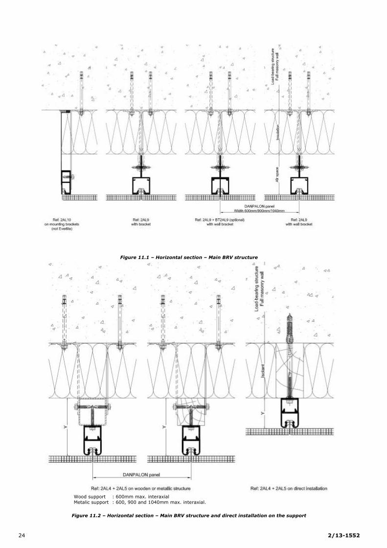
Figure 11.1 – Horizontal section – Main BRV structure .................................................................................................. 24
Figure 11.2 – Horizontal section – Main BRV structure and direct installation on the support ............................................. 24
Figure 11.3 – Horizontal section – Lateral stop ............................................................................................................ 25
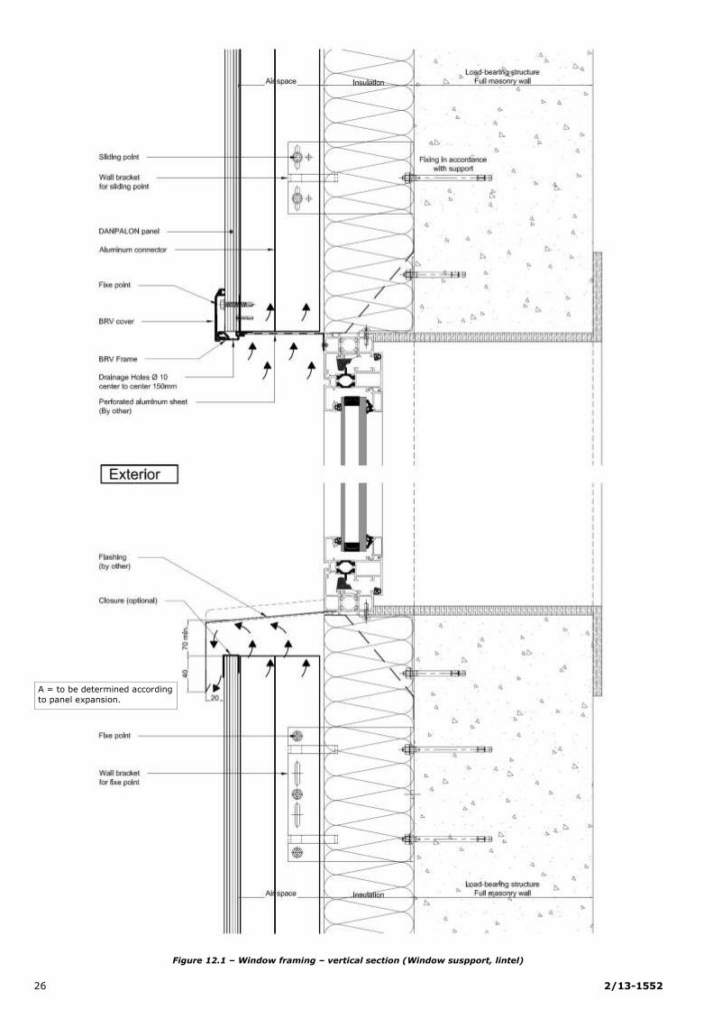
Figure 12.1 – Window framing – vertical section (Window support, lintel) ....................................................................... 26
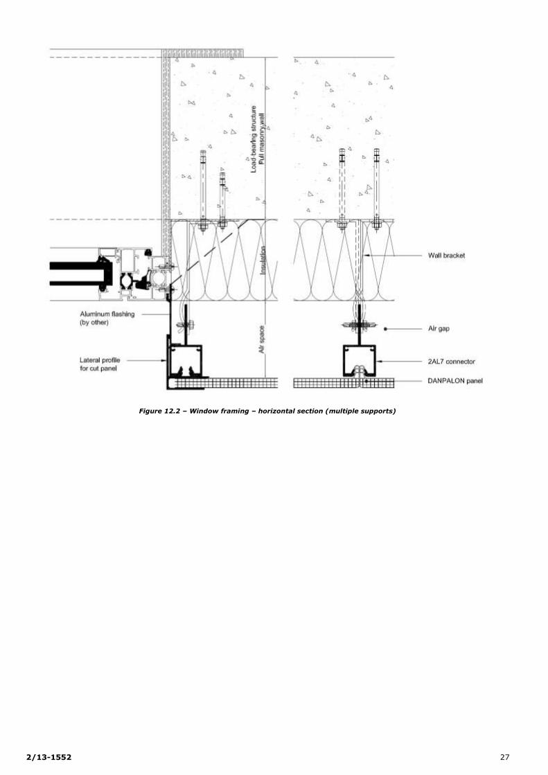
Figure 12.2 – Window framing – horizontal section (multiple supports) .......................................................................... 27
Figure 13 – Expansion joint ...................................................................................................................................... 28
Figure 14.1 – Recessed corner – With sheet metal paneling .......................................................................................... 29
Figure 14.2 – Internal corner – With sheet metal paneling ............................................................................................ 29
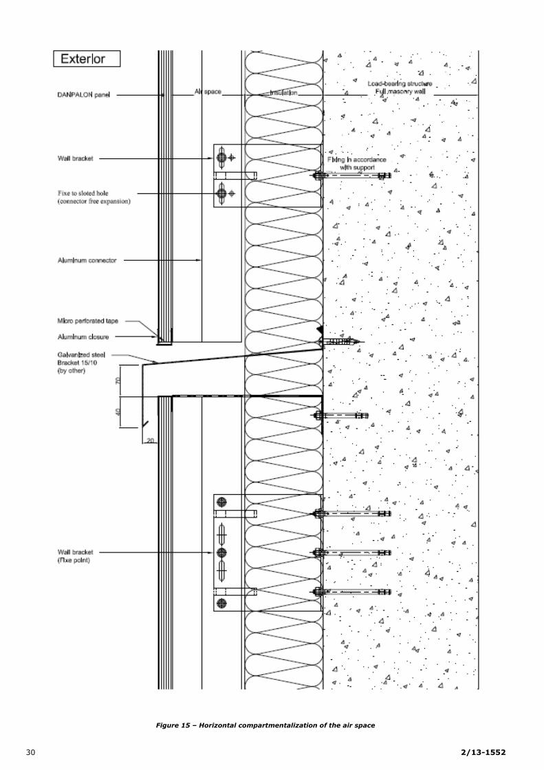
Figure 15 – Horizontal compartmentalization of the air space ........................................................................................ 30
Figure 16 – Structure division: BRV connectors ........................................................................................................... 31
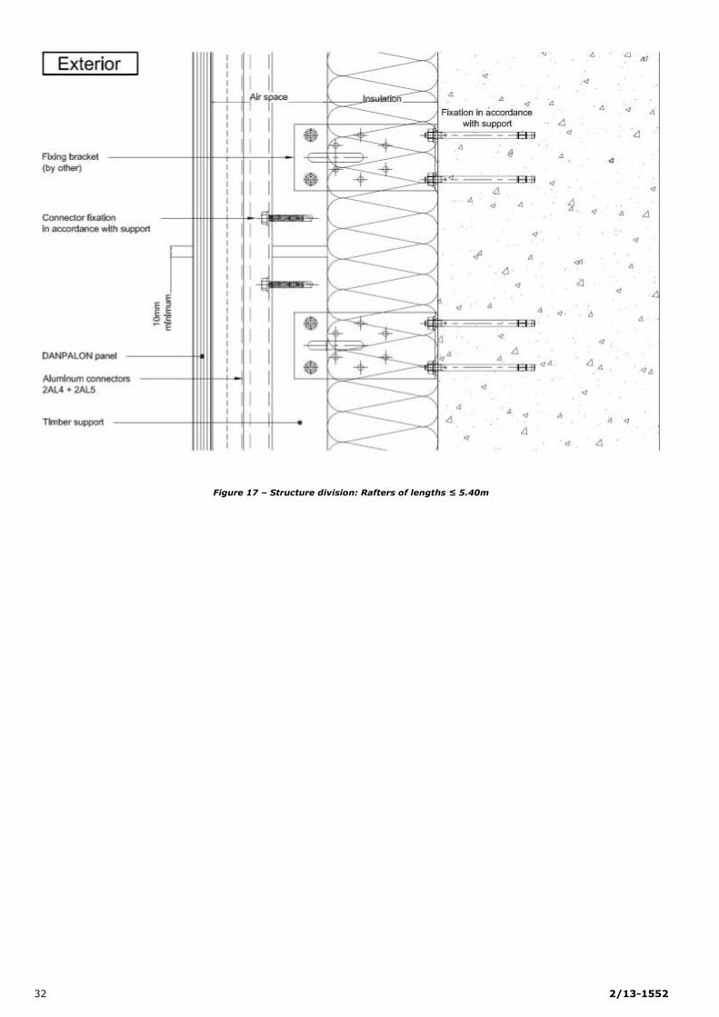
Figure 17 – Structure division: Rafters of lengths ≤ 5.40m ........................................................................................... 32
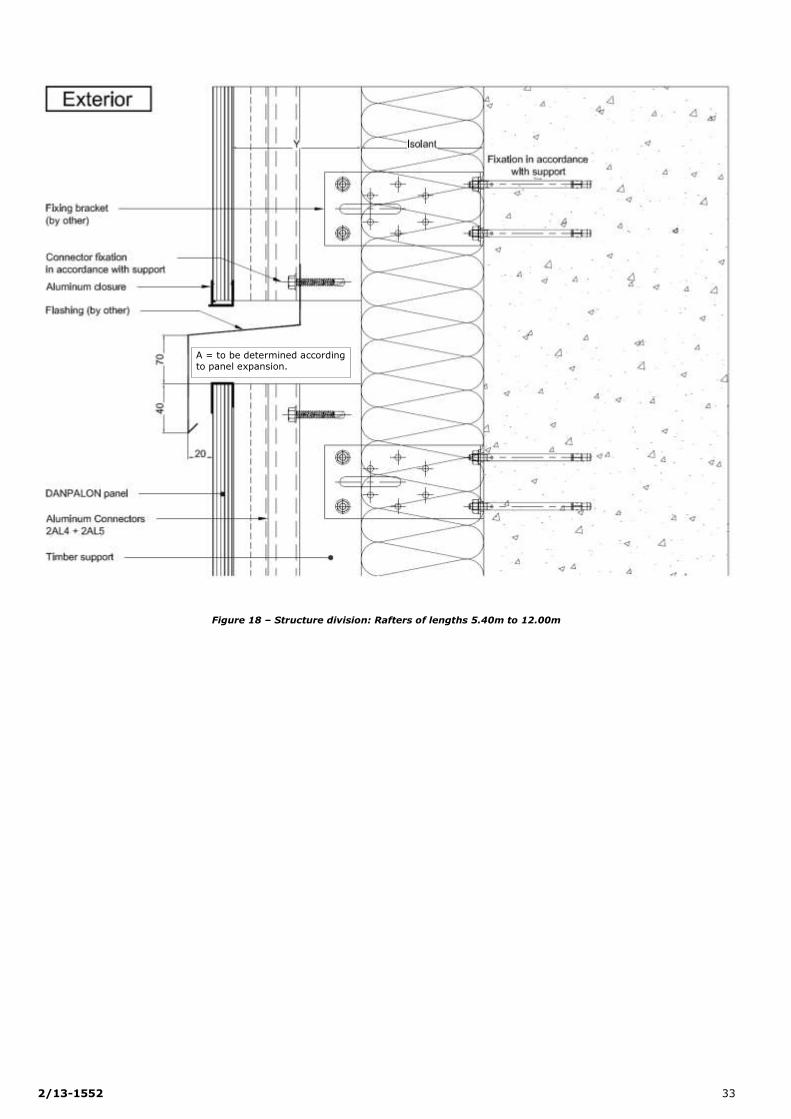
Figure 18 – Structure division: Rafters of lengths 5.40m to 12.00m ............................................................................... 33
Figure 19 – Structure division: Aluminum upright supports ≤ 6.00m .............................................................................. 34
Figure 20 – Soffite .................................................................................................................................................. 34
Annex A figures – Installation in areas of seismic activity ....................................................................................... 37
Figure A1 – Structure division directly on the base-boards ............................................................................................ 37
Figure A2 – Expansion joint from 12 to 15cm .............................................................................................................. 38
12 2/13-1552
Principle figures
Figure 1 – DANPALON® installation principles for BRV Structure
2/13-1552 13
Figure 2 – DANPALON® installation principles for Wood Structure
14 2/13-1552
Figure 3 – DANPALON® installation principles for Metallic Structure
2/13-1552 15
DANPALON® BRV system components
Figure 4.1 – DANPALON® panels
16 2/13-1552
Figure 4.2 – DANPALON® panels
2/13-1552 17
Figure 5.1 – Connectors on the primary structure
Figure 5.2 – BRV system connectors
18 2/13-1552
Figure 6 – Connector jointing – 2AL4/2AL5 connector principle
Ref: 4PC – Polycarbonate closure
Ref: 4ALPM – Aluminum closure, small model
Ref: 4ALGM – Aluminum closure, large model
Figure 7 – Closures
Aluminum connector 2AL4
Aluminum connector 2AL5
Junction
Junction
Upper purlin
Lower purlin
2/13-1552 19
Figure 8 – Aluminum finishing sections

20 2/13-1552
Installation details
Figure 9.1 – Vertical section
A = to be determined according
to panel expansion.
2/13-1552 21
Figure 9.2 – Vertical section at a positive slope of 15°
A = to be determined according to panel expansion.
22 2/13-1552
Figure 10.1 – Detailed vertical section for the installation at the low point of the 2AL4/2AL5 and 2AL7 connectors
2/13-1552 23
Figure 10.2 – Detailed vertical section for the installation at the low point of the 2AL9 connector
24 2/13-1552
Figure 11.1 – Horizontal section – Main BRV structure
Wood support : 600mm max. interaxial
Metalic support : 600, 900 and 1040mm max. interaxial.
Figure 11.2 – Horizontal section – Main BRV structure and direct installation on the support
2/13-1552 25
Figure 11.3 – Horizontal section – Lateral stop
26 2/13-1552
Figure 12.1 – Window framing – vertical section (Window suspport, lintel)
A = to be determined according
to panel expansion.
2/13-1552 27
Figure 12.2 – Window framing – horizontal section (multiple supports)
28 2/13-1552
Figure 13 – Expansion joint
2/13-1552 29
Figure 14.1 – Recessed corner – With sheet metal paneling
Figure 14.2 – Internal corner – With sheet metal paneling
30 2/13-1552
Figure 15 – Horizontal compartmentalization of the air space

2/13-1552 31
Figure 16 – Structure division: BRV connectors
32 2/13-1552
Figure 17 – Structure division: Rafters of lengths ≤ 5.40m
2/13-1552 33
Figure 18 – Structure division: Rafters of lengths 5.40m to 12.00m
A = to be determined according to panel expansion.

34 2/13-1552
Figure 19 – Structure division: Aluminum upright supports ≤ 6.00m
Figure 20 – Underside paneling
2/13-1552 35
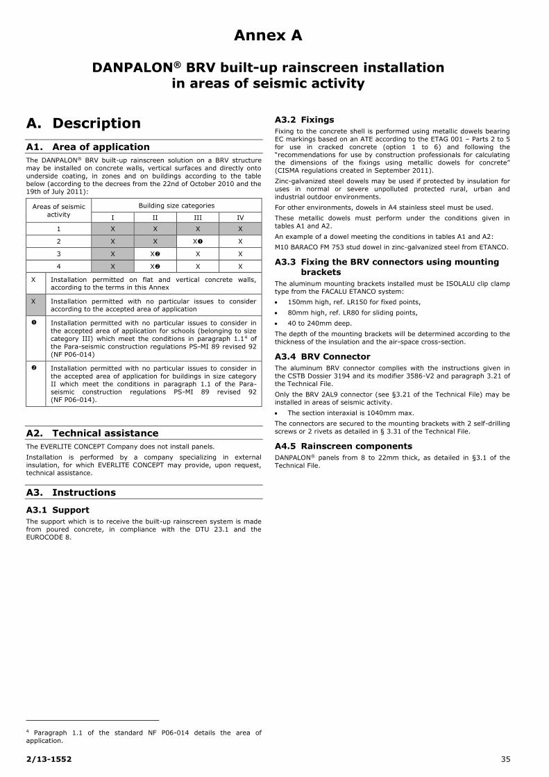
Annex A
DANPALON® BRV built-up rainscreen installation
in areas of seismic activity
A. Description
A1. Area of application
The DANPALON® BRV built-up rainscreen solution on a BRV structure
may be installed on concrete walls, vertical surfaces and directly onto
underside coating, in zones and on buildings according to the table
below (according to the decrees from the 22nd of October 2010 and the 19th of July 2011):
Areas of seismic
activity
Building size categories
I II III IV
1 X X X X
2 X X X X
3 X X X X
4 X X X X
X Installation permitted on flat and vertical concrete walls, according to the terms in this Annex
X Installation permitted with no particular issues to consider according to the accepted area of application
Installation permitted with no particular issues to consider in
the accepted area of application for schools (belonging to size
category III) which meet the conditions in paragraph 1.14 of
the Para-seismic construction regulations PS-MI 89 revised 92
(NF P06-014)
Installation permitted with no particular issues to consider in
the accepted area of application for buildings in size category
II which meet the conditions in paragraph 1.1 of the Para-
seismic construction regulations PS-MI 89 revised 92
(NF P06-014).
A2. Technical assistance
The EVERLITE CONCEPT Company does not install panels.
Installation is performed by a company specializing in external
insulation, for which EVERLITE CONCEPT may provide, upon request,
technical assistance.
A3. Instructions
A3.1 Support
The support which is to receive the built-up rainscreen system is made
from poured concrete, in compliance with the DTU 23.1 and the
EUROCODE 8.
4 Paragraph 1.1 of the standard NF P06-014 details the area of
application.
A3.2 Fixings
Fixing to the concrete shell is performed using metallic dowels bearing
EC markings based on an ATE according to the ETAG 001 – Parts 2 to 5
for use in cracked concrete (option 1 to 6) and following the
“recommendations for use by construction professionals for calculating the dimensions of the fixings using metallic dowels for concrete”
(CISMA regulations created in September 2011).
Zinc-galvanized steel dowels may be used if protected by insulation for
uses in normal or severe unpolluted protected rural, urban and
industrial outdoor environments.
For other environments, dowels in A4 stainless steel must be used.
These metallic dowels must perform under the conditions given in
tables A1 and A2.
An example of a dowel meeting the conditions in tables A1 and A2:
M10 BARACO FM 753 stud dowel in zinc-galvanized steel from ETANCO.
A3.3 Fixing the BRV connectors using mounting
brackets
The aluminum mounting brackets installed must be ISOLALU clip clamp
type from the FACALU ETANCO system:
150mm high, ref. LR150 for fixed points,
80mm high, ref. LR80 for sliding points,
40 to 240mm deep.
The depth of the mounting brackets will be determined according to the
thickness of the insulation and the air-space cross-section.
A3.4 BRV Connector
The aluminum BRV connector complies with the instructions given in
the CSTB Dossier 3194 and its modifier 3586-V2 and paragraph 3.21 of
the Technical File.
Only the BRV 2AL9 connector (see §3.21 of the Technical File) may be
installed in areas of seismic activity.
The section interaxial is 1040mm max.
The connectors are secured to the mounting brackets with 2 self-drilling
screws or 2 rivets as detailed in § 3.31 of the Technical File.
A4.5 Rainscreen components
DANPALON® panels from 8 to 22mm thick, as detailed in §3.1 of the
Technical File.

36 2/13-1552
Tables and figures of Annex A
Table A1 – Applied traction-shearing stress on the metallic dowel on a 40mm long mounting bracket for installation on a BRV
framework
According to the decrees from the 22nd of October 2010 and the 19th of July 2011 and the Eurocode 8
Stress
Area of
seismic activity
Perpendicular to the façade Parallel to the façade
Building size category classes Building size category classes
II III IV II III IV
Traction [N]
2 87 91 87 91
3 94 100 106 94 100 106
4 108 116 125 108 116 125
Shearing [N]
2 43 43 44 44
3 43 43 43 44 45 45
4 43 43 43 45 46 48
Table A2 – Applied traction-shearing stress on the metallic dowel on a 240mm long mounting bracket for installation on a BRV
framework
According to the decrees from the 22nd of October 2010 and the 19th of July 2011 and the Eurocode 8
Stress Area of seismic
activity
Perpendicular to the façade Parallel to the façade
Building size category classes Building size category classes
II III IV II III IV
Traction [N]
2 411 414 524 547
3 418 424 430 566 602 637
4 431 440 448 647 699 750
Shearing [N]
2 43 43 44 44
3 43 43 43 44 45 45
4 43 43 43 45 46 48
Area with no particular seismic requirements.

2/13-1552 37
Annex A figures – Installation in areas of seismic activity
Figure A1 – Structure division directly on the base-boards
A = to be determined according
to panel expansion.
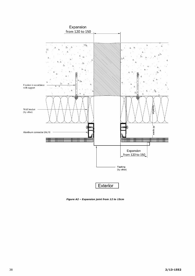
38 2/13-1552
Figure A2 – Expansion joint from 12 to 15cm