pompe centrifuge type wk / wkn - schmalenberger.de · eg-konformitätserklärung déclaration de...
TRANSCRIPT

Kreiselpumpe Typ WK / WKNBetriebsanleitung Nr. 27220 - A
Pompe centrifuge type WK / WKNNotice d´Utilisation No. 27220 - A
Centrifugal pump type WK / WKNOperator´s manual No. 27220 - A
Schmalenberger GmbH & Co. KGStrömungstechnologieGermany
EG-KonformitätserklärungDéclaration de conformité pour la CEE / EC-Declaration of Conformity
Hersteller / fabricant / manufacturerSchmalenberger GmbH+Co. KGStrömungstechnologieIm Schelmen 9-11D-72072 Tübingen / Germany
Produkt / produit / productKreiselpumpen / Pompes centrifuges / Circulating pumps
Typ / modèle / modelWK / WKN
Hiermit erklären wir, dass die spezifische Bauart in Übereinstimmung mit den folgenden Richtlinien hergestellt worden ist:Par la présente, nous declarons, que le type de est produit conforme aux dispositions des directives européenne sci après:We hereby declare that the specific type has been produced in accordance with the following standards:
EG - Richtlinien / Directives de la CEE / EEC Directives
EG-Maschinen-Richtlinie (98/37/EG), Directives machines EU (98/37/EG), EU maschine directive (98/37/EG)
Niederspannungsrichtlinie (73/23/EWG f.), Directives basse tension (73/23/EWG f.), Low tension directive (73/23/EWG f.)
Zur sachgerechten Umsetzung der in der EG-Richtline genannten Sicherheits- und Gesundheitsanforderungen wurde(n) folgende Norm(en) herangezogen:Pour mettre en partique dans les règles de l’art les prescritions en matière de sécurité et de santé stipulées dans les Directives de la CEE, il a été tenu compte de la /des norme(s):For the relevant implementation of the safety and health requirements mentioned in the Directives, the following standard(s) must be required:
Harmonisierte Normen / Normes harmonisées / Harmonised Standards
DIN EN 292: Sicherheit von Maschinen, Grundbegriffe, allgemeine GestaltungsleitsätzeDIN EN 292: Sécurité des machines, concepts de base, principes directeurs généraux de mise en oeuvreDIN EN 292: Machine safety, basic concepts, formal basic principles
DIN EN 292, Teil 1: Grundsätzliche Terminologie, MethodikDIN EN 292, 1ère Partie: Terminologie de base, méthodologieDIN EN 292, Part 1: Basic terminology, methodology
DIN EN 292, Teil 2: Technische Leitsätze und SpezifikationenDIN EN 292, 2ème Partie: Principes directeurs techniques et spécificationsDIN EN 292, Part 2: Technical principles and specifications
EN 60034-1 (DIN VDE 0530 Teil 1): Drehende elektrische MaschinenEN 60034-1 (DIN VDE 0530 1ère Partie): Machines rotatives électriquesEN 60034-1 (DIN VDE 0530 Part 1): Rotating electrical machines
EN 60034-5 (DIN VDE 0530-5): Einteilung der Schutzarten durch Gehäuse für umlaufende MaschinenEN 60034-5 (DIN VDE 0530-5): Attribution des types de protection par des boîtiers pour des machines en mouvementEN 60034-5 (DIN VDE 0530-5): Assigment of protection types for rotating machines
DIN EN 60204: Sicherheit von Maschinen; Elektrische Ausrüstung von MaschinenDIN EN 60204: Sécurité des machines; équipment électrique des machinesDIN EN 60204: Machine safety; electrical machine equipment
DIN EN 20204, Teil 1: Allgemeine Anforderungen (Elektromotoren)DIN EN 20204, 1ère Partie: Exigences générales (moteurs électriques)DIN EN 20204, Part 1: General requirements (electrical motors)
Schmalenberger GmbH+Co. KG
Tübingen, den 1. Mai 2002Unterschrift:
-------------------------------------------------------------------------------------------------Leiter Qualitätssicherung / Directeur d’assurance de la qualité /
Manager of quality assurance
2 Pumpe Typ WK / WKNVersion: 27220 - A
Schmalenberger GmbH + Co. KG D-72072 Tübingen / Germany

INHALTSVERZEICHNIS / CONTENU / CONTENTS
3Pumpe Typ WK / WKNVersion: 27220 - A
Schmalenberger GmbH + Co. KG D-72072 Tübingen / Germany
Inhaltsverzeichnis
1 Allgemeine Angaben ...................................................................... 13
1.1 Benutzerinformation ...................................................................................................... 13
1.2 Bestimmungsgemäße Verwendung .............................................................................. 14
1.3 Mitgeltende Dokumente................................................................................................. 16
1.4 Technische Daten - Spezifikation .................................................................................. 181.4.1 Motortypenschild ............................................................................................................201.4.2 Pumpentypenschild ........................................................................................................21
2 Sicherheitshinweise ....................................................................... 26
2.1 Allgemeines ................................................................................................................... 26
2.2 Zeichen und Symbole.................................................................................................... 26
2.3 Verpflichtung des Betreibers ......................................................................................... 30
2.4 Sicherheitshinweise zur Aufstellung .............................................................................. 30
2.5 Sicherheitshinweise zum Anschluss.............................................................................. 30
2.6 Sicherheitshinweise zur Inbetriebnahme....................................................................... 34
2.7 Sicherheitshinweise für den Betrieb .............................................................................. 342.7.1 Temperatur .....................................................................................................................342.7.2 Leckageabfuhr................................................................................................................34
2.8 Sicherheitshinweise für Wartung und Reparaturarbeiten .............................................. 34
2.9 Sicherheitshinweise für die Ausserbetriebnahme.......................................................... 34
2.10 Potentielle Risikoquellen der Kreiselpumpe .................................................................. 38
2.11 Gerätebeschreibung ...................................................................................................... 42
3 Transport, Lagerung, Montage ...................................................... 44
3.1 Transport und Lagerung ................................................................................................ 443.1.1 Transport ........................................................................................................................443.1.2 Lagerung ........................................................................................................................463.1.3 Konservierung ................................................................................................................47
3.2 Auspacken, Reinigung und Zusammenbau................................................................... 483.2.1 Auspacken......................................................................................................................483.2.2 Reinigen .........................................................................................................................483.2.3 Zusammenbau................................................................................................................52
3.3 Aufstellen und Anschließen ........................................................................................... 533.3.1 Überprüfen Sie vor Aufstellungsbeginn ..........................................................................543.3.2 Ein- und Aufbau der Kreiselpumpe.................................................................................553.3.3 Anschließen der Rohrleitungen ......................................................................................55

INHALTSVERZEICHNIS / CONTENU / CONTENTS
4 Pumpe Typ WK / WKNVersion: 27220 - A
Schmalenberger GmbH + Co. KG D-72072 Tübingen / Germany
4 Elektrischer Anschluss .................................................................. 58
4.1 Elektrischer Anschluss allgemein ................................................................................. 584.1.1 Drehrichtungsprüfung .................................................................................................... 624.1.2 Motor-Zusatzeinrichtungen ............................................................................................ 62
4.2 Klemmenkasten öffnen / schließen (nur bei Typ WKN) ................................................ 644.2.1 Klemmenkasten öffnen .................................................................................................. 644.2.2 Klemmenkasten schließen............................................................................................. 66
4.3 Elektrischer Anschluss Pumpe Typ WK....................................................................... 684.3.1 Wechselstrom Typ WK .................................................................................................. 684.3.2 Drehstrom Typ WK ........................................................................................................ 70
4.4 Elektrischer Anschluss Pumpe Typ WKN..................................................................... 744.4.1 Wechselstrom Typ WKN................................................................................................ 744.4.1.1 Anschlusskabel der Netzzuleitung an Platine anschließen (Typ WKN, Wechselstrom) 76
4.4.2 Drehstrom Typ WKN...................................................................................................... 784.4.2.1 Anschlusskabel der Netzzuleitung an Platine anschließen (Typ WKN, Drehstrom) ...... 80
4.4.3 Einstellung der Betriebsdauer........................................................................................ 824.4.4 Einstellung der Empfängeradresse................................................................................ 84
5 Geräteeinheiten............................................................................... 86
5.1 Pumpenbausatz Typ WK .............................................................................................. 86
5.2 Pumpenbausatz Typ WKN............................................................................................ 885.2.1 Sendeeinheit Typ mono ................................................................................................. 88
6 Montage ........................................................................................... 92
6.1 Montage allgemein........................................................................................................ 92
6.2 Montage des Schaltkastens (nur bei Typ WK).............................................................. 92
6.3 Montage der Antenne (nur bei Typ WKN)..................................................................... 94
6.4 Montage des Senders................................................................................................... 96
6.5 Anschluss Pumpenansteuerung (nur bei Typ WKN) .................................................... 986.5.1 Funkansteuerung ........................................................................................................... 986.5.2 Externe Ansteuerung ..................................................................................................... 986.5.3 Pneumatische Ansteuerung........................................................................................... 98
7 Betrieb der Kreiselpumpe ............................................................ 100
7.1 Erstinbetriebnahme..................................................................................................... 1007.1.1 Kreiselpumpe starten ................................................................................................... 100
7.2 Betreiben..................................................................................................................... 1047.2.1 Betriebsüberwachung .................................................................................................. 1047.2.2 Sonstiges ..................................................................................................................... 104
7.3 Hinweise auf Fehlbedienung....................................................................................... 1087.3.1 Allgemein ..................................................................................................................... 1087.3.2 Störungen .................................................................................................................... 110
7.4 Stillsetzen.................................................................................................................... 112
7.5 Pumpe entleeren......................................................................................................... 114

INHALTSVERZEICHNIS / CONTENU / CONTENTS
5Pumpe Typ WK / WKNVersion: 27220 - A
Schmalenberger GmbH + Co. KG D-72072 Tübingen / Germany
8 Fehlerhilfe...................................................................................... 116
8.1 Fehlerhilfe bei Typ WK ................................................................................................ 116
8.2 Fehlerhilfe bei Typ WKN.............................................................................................. 120
9 Wartung / Instandsetzung ............................................................ 126
9.1 Allgemeine Hinweise ................................................................................................... 126
9.2 Wartung / Inspektion.................................................................................................... 1269.2.1 Schmierung und Schmiermittelwechsel........................................................................130
9.3 Instandsetzung ............................................................................................................ 1309.3.1 Allgemein......................................................................................................................1309.3.2 Demontagevorbereitung ...............................................................................................1309.3.3 Demontage / Ausbau der Pumpe .................................................................................134
9.4 Demontage / Kreiselpumpe zerlegen .......................................................................... 1389.4.1 Bevor Sie beginnen ......................................................................................................138
9.5 Austausch des Sendeknopfes ..................................................................................... 140
9.6 Ersatzteilliste / Zeichnung............................................................................................ 140
10 Anhang........................................................................................... 142
10.1 Außerbetriebnahme / Einlagerung / Konservierung .................................................... 14210.1.1 Einlagerung neuer Pumpen..........................................................................................14210.1.2 Längere Außerbetriebnahme > 3 Monate.....................................................................14310.1.3 Wiederinbetriebnahme nach Einlagerung ....................................................................144
10.2 Entsorgung .................................................................................................................. 148
10.3 Wichtige Hinweise ....................................................................................................... 15010.3.1 Werksreparatur .............................................................................................................15010.3.2 Ersatzteilbestellung ......................................................................................................151
11 Ersatzteilliste und Zeichnung ...................................................... 155
11.1 Typ WK........................................................................................................................ 155
11.2 Typ WKN ..................................................................................................................... 159

INHALTSVERZEICHNIS / CONTENU / CONTENTS
6Pumpe Typ WK / WKNVersion: 27220 - A
Schmalenberger GmbH + Co. KG D-72072 Tübingen / Germany
Contenu
1 Données générales ......................................................................... 13
1.1 Informations utilisateur .................................................................................................. 13
1.2 Utilisation conforme à la finalité ..................................................................................... 14
1.3 Documents ayant covalidité........................................................................................... 16
1.4 Caractéristiques techniques - Spécification................................................................... 181.4.1 Plaque signalétique du moteur ...................................................................................... 201.4.2 Plaque signalétique de la pompe .................................................................................. 21
2 Consignes de sécurité.................................................................... 27
2.1 Généralités .................................................................................................................... 27
2.2 Signes et symboles ....................................................................................................... 27
2.3 Obligations de l’exploitant.............................................................................................. 31
2.4 Consignes de sécurité concernant l’installation............................................................. 31
2.5 Consignes de sécurité pour le raccordement ................................................................ 31
2.6 Consignes de sécurité pour la mise en service ............................................................. 35
2.7 Consignes de sécurité pour l’exploitation ...................................................................... 352.7.1 Température .................................................................................................................. 352.7.2 Ecoulement des fuites ................................................................................................... 35
2.8 Consignes de sécurité pour l’entretien et les travaux de réparation.............................. 35
2.9 Consignes de sécurité pour la mise hors service .......................................................... 35
2.10 Sources de risque potentielles de la pompe centrifuge................................................. 39
2.11 Descriptif de l’appareil ................................................................................................... 42
3 Transport, entreposage, montage................................................. 45
3.1 Transport et entreposage .............................................................................................. 453.1.1 Transport ....................................................................................................................... 453.1.2 Entreposage .................................................................................................................. 463.1.3 Conservation ................................................................................................................. 47
3.2 Déballage, nettoyage et montage.................................................................................. 493.2.1 Déballage ...................................................................................................................... 493.2.2 Nettoyage ...................................................................................................................... 493.2.3 Montage......................................................................................................................... 52
3.3 Installation et raccordement .......................................................................................... 533.3.1 Vérifier avant le début de l’installation ........................................................................... 543.3.2 Montage intégré et montage sur fondation de la pompe centrifuge .............................. 563.3.3 Raccordement des conduites ........................................................................................ 56
INHALTSVERZEICHNIS / CONTENU / CONTENTS
7Pumpe Typ WK / WKNVersion: 27220 - A
Schmalenberger GmbH + Co. KG D-72072 Tübingen / Germany
4 Branchement électrique ................................................................. 59
4.1 Branchement électrique en général............................................................................... 594.1.1 Vérification du sens de rotation ..................................................................................... 624.1.2 Dispositifs supplémentaires du moteur.......................................................................... 62
4.2 Ouverture / fermeture de la / boîte à bornes (que pour le type WKN).......................... 654.2.1 Ouverture de la boîte à bornes...................................................................................... 654.2.2 Fermeture de la boîte à bornes ..................................................................................... 67
4.3 Branchement électrique Pompe du type WK................................................................. 694.3.1 Courant alternatif type WK ............................................................................................ 694.3.2 Courant triphasé type WK ............................................................................................. 71
4.4 Branchement électrique Pompe du type WKN .............................................................. 754.4.1 Courant alternatif type WKN.......................................................................................... 754.4.1.1 Branchement du câble de raccordement de la ligne d’alimentation réseau
sur la platine (Courant alternatif type WKN) .................................................................. 77
4.4.2 Courant triphasé type WKN........................................................................................... 794.4.2.1 Branchement du câble de raccordement de la ligne d’alimentation réseau
sur la platine (Courant triphasé type WKN) ................................................................... 81
4.4.3 Réglage de la durée du fonctionnement........................................................................ 834.4.4 Réglage de l’adresse du récepteur................................................................................ 85
5 Unités de l’appareil ......................................................................... 87
5.1 Module de pompe type WK ........................................................................................... 87
5.2 Module de pompe type WKN......................................................................................... 895.2.1 Unité émettrice type mono............................................................................................. 89
6 Montage ........................................................................................... 93
6.1 Montage en général....................................................................................................... 93
6.2 Montage du coffret électrique (uniquement pour le type WK) ....................................... 93
6.3 Montage de l’antenne (uniquement pour le type WKN)................................................. 95
6.4 Montage de l’émetteur................................................................................................... 97
6.5 Raccordement commande de pompe (que pour le type WKN)..................................... 996.5.1 Commande radio ........................................................................................................... 996.5.2 Commande externe ....................................................................................................... 996.5.3 Commande pneumatique .............................................................................................. 99

INHALTSVERZEICHNIS / CONTENU / CONTENTS
8 Pumpe Typ WK / WKNVersion: 27220 - A
Schmalenberger GmbH + Co. KG D-72072 Tübingen / Germany
7 Exploitation de la pompe centrifuge ........................................... 101
7.1 Première mise en service ........................................................................................... 1017.1.1 Démarrage de la pompe centrifuge ............................................................................ 101
7.2 Exploitation ................................................................................................................. 1057.2.1 Surveillance du fonctionnement.................................................................................. 1057.2.2 Autres.......................................................................................................................... 105
7.3 Informations relatives à une fausse manœuvre.......................................................... 1087.3.1 Généralités.................................................................................................................. 1087.3.2 Anomalies ................................................................................................................... 110
7.4 Mise à l’arrêt ............................................................................................................... 112
7.5 Vidange de la pompe .................................................................................................. 115
8 Aide aux défauts ........................................................................... 117
8.1 Aide aux défauts pour le type WK............................................................................... 117
8.2 Aide aux défauts pour le type WKN............................................................................ 122
9 Entretien / maintenance................................................................ 127
9.1 Consignes générales .................................................................................................. 127
9.2 Entretien / révision ...................................................................................................... 1279.2.1 Lubrification et vidange du lubrifiant ........................................................................... 131
9.3 Remise en état............................................................................................................ 1319.3.1 Généralités.................................................................................................................. 1319.3.2 Préparation du démontage. ........................................................................................ 1319.3.3 Démontage / Démontage de la pompe ....................................................................... 135
9.4 Démontage / Désassemblage de la pompe centrifuge ............................................... 1389.4.1 Avant de commencer .................................................................................................. 138
9.5 Remplacement de la tête émettrice ............................................................................ 141
9.6 Liste des pièce détachées / Schéma .......................................................................... 141
10 Annexes ......................................................................................... 142
10.1 Mise hors service / Entreposage / Conservation ........................................................ 14210.1.1 Entreposage de pompes neuves ................................................................................ 14210.1.2 Mise hors service prolongée > 3 mois ........................................................................ 14310.1.3 Remise en service après entreposage ....................................................................... 145
10.2 Mise au rebut .............................................................................................................. 148
10.3 Informations importantes ............................................................................................ 15010.3.1 Réparation d’usine ...................................................................................................... 15010.3.2 Commande de pièces de rechange ............................................................................ 151
11 Liste de pièces détachées et schéma ......................................... 155
11.1 Type WK ..................................................................................................................... 155
11.2 Type WKN................................................................................................................... 159

INHALTSVERZEICHNIS / CONTENU / CONTENTS
9Pumpe Typ WK / WKNVersion: 27220 - A
Schmalenberger GmbH + Co. KG D-72072 Tübingen / Germany
Contents
1 General Details................................................................................ 13
1.1 User Information ............................................................................................................ 13
1.2 Usage Instructions......................................................................................................... 15
1.3 Relevant Documentation ............................................................................................... 17
1.4 Technical Data - Specifications ..................................................................................... 191.4.1 Motor type plate..............................................................................................................201.4.2 Pump type plate..............................................................................................................21
2 Safety Instructions.......................................................................... 28
2.1 General.......................................................................................................................... 28
2.2 Signs and Symbols........................................................................................................ 28
2.3 User Responsibilities ..................................................................................................... 32
2.4 Safety Instructions for Installation.................................................................................. 32
2.5 Safety Instructions for Connection................................................................................. 32
2.6 Safety Instructions for Start-up ...................................................................................... 36
2.7 Safety Instructions for Operation ................................................................................... 362.7.1 Temperature ...................................................................................................................362.7.2 Leakage drainage...........................................................................................................36
2.8 Safety Instructions for Maintenance and Repairs.......................................................... 36
2.9 Safety information for shut-down................................................................................... 36
2.10 Potential Sources of Risk with the Centrifugal Pump .................................................... 40
2.11 Description of the Unit ................................................................................................... 43
3 Transport, Storage, Installation..................................................... 45
3.1 Transport and Storage................................................................................................... 453.1.1 Transport ........................................................................................................................453.1.2 Storage ...........................................................................................................................463.1.3 Conservation ..................................................................................................................47
3.2 Unpacking, Cleaning and Assembling........................................................................... 503.2.1 Unpacking.......................................................................................................................503.2.2 Cleaning .........................................................................................................................503.2.3 Assembling .....................................................................................................................52
3.3 Installing and Connecting .............................................................................................. 533.3.1 Check before you start installing ....................................................................................543.3.2 Installing and Erecting the Centrifugal Pump .................................................................573.3.3 Connecting the Pipework................................................................................................57

INHALTSVERZEICHNIS / CONTENU / CONTENTS
10 Pumpe Typ WK / WKNVersion: 27220 - A
Schmalenberger GmbH + Co. KG D-72072 Tübingen / Germany
4 Electrical Connections ................................................................... 60
4.1 Electrical Connections - general ................................................................................... 604.1.1 Direction of rotation check ............................................................................................. 634.1.2 Additional motor equipment ........................................................................................... 63
4.2 Open / close terminal box (only for type WKN)............................................................. 654.2.1 Open terminal box.......................................................................................................... 654.2.2 Close terminal box ......................................................................................................... 67
4.3 Electrical Connections Pump type WK ......................................................................... 694.3.1 Alternating current type WK ........................................................................................... 694.3.2 Three-phase current type WK........................................................................................ 71
4.4 Electrical Connections Pump type WKN....................................................................... 754.4.1 Alternating current type WKN ........................................................................................ 754.4.1.1 Connecting the mains power supply cable to the printed circuit board
(Alternating current type WKN) ...................................................................................... 77
4.4.2 Three-phase current type WKN ..................................................................................... 794.4.2.1 Connecting the mains power supply cable to the printed circuit board
(Three-phase current type WKN)................................................................................... 81
4.4.3 Setting the operating time .............................................................................................. 834.4.4 Setting the receiver address .......................................................................................... 85
5 Device Units..................................................................................... 87
5.1 Pump kit type WK ......................................................................................................... 87
5.2 Pump kit type WKN....................................................................................................... 895.2.1 Transmitter type mono ................................................................................................... 89
6 Installation ....................................................................................... 93
6.1 Installation - general...................................................................................................... 93
6.2 Installing the switchgear box (only for type WK) ........................................................... 93
6.3 Installing the aerial(only for type WKN)....................................................................................................... 95
6.4 Installing the transmitter................................................................................................ 97
6.5 Pump control connection (only for type WKN) .............................................................. 996.5.1 Radio control.................................................................................................................. 996.5.2 External control .............................................................................................................. 996.5.3 Pneumatic control .......................................................................................................... 99

INHALTSVERZEICHNIS / CONTENU / CONTENTS
11Pumpe Typ WK / WKNVersion: 27220 - A
Schmalenberger GmbH + Co. KG D-72072 Tübingen / Germany
7 Operating the Centrifugal Pump.................................................. 102
7.1 Initial Start-up .............................................................................................................. 1027.1.1 Start the centrifugal pump ............................................................................................102
7.2 Operating..................................................................................................................... 1067.2.1 Operation Monitoring ....................................................................................................1067.2.2 Miscellaneous...............................................................................................................106
7.3 Indications of Faulty Operation.................................................................................... 1097.3.1 General.........................................................................................................................1097.3.2 Faults............................................................................................................................111
7.4 Shutdown..................................................................................................................... 112
7.5 Emptying the pump...................................................................................................... 115
8 Fault Assistance ........................................................................... 118
8.1 Fault assistance for type WK....................................................................................... 118
8.2 Fault assistance for type WKN .................................................................................... 124
9 Maintenance / Repair .................................................................... 128
9.1 General Instructions .................................................................................................... 128
9.2 Maintenance / Service ................................................................................................. 1289.2.1 Lubrication and Changing Lubricants ...........................................................................132
9.3 Repair .......................................................................................................................... 1329.3.1 General.........................................................................................................................1329.3.2 Dismantling Preparations .............................................................................................1329.3.3 Dismantling / Removal of the Centrifugal Pump...........................................................136
9.4 Dismantling / Dismantling the Centrifugal Pump ......................................................... 1399.4.1 Before you begin ..........................................................................................................139
9.5 Replacing the transmitter head.................................................................................... 141
9.6 Spare Parts List / Drawing........................................................................................... 141
10 Appendix........................................................................................ 142
10.1 Shutdown / Storage / Conservation............................................................................. 14210.1.1 Storage of new Pumps .................................................................................................14210.1.2 Longer Periods of Shutdown > 3 months .....................................................................14310.1.3 Restarting after Periods of Storage ..............................................................................146
10.2 Disposal....................................................................................................................... 149
10.3 Important Instructions .................................................................................................. 15010.3.1 Factory repair ...............................................................................................................15010.3.2 Ordering Spare Parts....................................................................................................151
11 Spare Parts List and Drawing ...................................................... 155
11.1 Type WK...................................................................................................................... 155
11.2 Type WKN ................................................................................................................... 159

12 Pumpe Typ WK / WKNVersion: 27220 - A
Schmalenberger GmbH + Co. KG D-72072 Tübingen / Germany
BETRIEBSANLEITUNG / NOTICE D´UTILISATION / OPERATOR´S MANUAL

13Pumpe Typ WK / WKNVersion: 27220 - A
Schmalenberger GmbH + Co. KG D-72072 Tübingen / Germany
BETRIEBSANLEITUNG / NOTICE D´UTILISATION / OPERATOR´S MANUAL
1 Données générales1.1 Informations utilisateur
Cette notice d’utilisation a pour objectif de faciliter la familiarisation avec la pompecentrifuge et de permettre l’application de ses possibilités d’utilisation dans leur intégralité.Cette notice d’utilisation contient des informations importantes relatives à une exploitationfiable, compétente et rentable de la pompe centrifuge. Le respect de cette notice permettrad’une part d’éviter les dangers, les frais de réparation et les temps de panne et d’autre partd’augmenter la durée de vie de la pompe centrifuge.La notice d’utilisation ne prend pas en compte les impératifs locaux : l’exploitant estresponsable de leur respect. La plaque de type reprend la gamme, la taille, les données de fonctionnement importanteset le numéro d’usine. Nous vous prions de toujours indiquer ces renseignements pour tousréassortiments, demandes et commandes de pièces de rechange.
1 Allgemeine Angaben1.1 Benutzerinformation
Diese Betriebsanleitung erleichtert es, die Kreiselpumpe kennenzulernen und ihre Einsatz-möglichkeiten voll zu nutzen.Die Betriebsanleitung enthält wichtige Hinweise, die Kreiselpumpe sicher, sachgerechtund wirtschaftlich zu betreiben. Ihre Beachtung hilft, Gefahren zu vermeiden, Reparatur-kosten und Ausfallzeiten zu vermindern, die Zuverlässigkeit und die Lebensdauer der Krei-selpumpe zu erhöhen.Die Betriebsanleitung berücksichtigt nicht die ortsbezogenen Bestimmungen, für derenEinhaltung der Betreiber verantwortlich ist. Das Pumpenschild nennt die Baureihe, die Baugröße, die wichtigsten Betriebsdaten unddie Werknummer. Wir bitten Sie, diese bei Rückfragen, Nachbestellung und insbesonderebei Bestellung von Ersatzteilen stets anzugeben.
1 General Details1.1 User Information
This operator’s manual makes it easier to get to know the centrifugal pump and to makefull use of its facilities.The operator’s manual contains important instructions how to use the centrifugal pumpsafely, properly and economically. Your careful attention to these instructions will help toavoid danger, to reduce repair costs and breakdowns and to increase the reliability anduseful life of the centrifugal pump.The operator’s manual does not take account of local regulations. The user is responsiblefor ensuring that they are complied with. The label specifies the machine series, the frame size, the most important operating dataand the serial number. We request that you always quote it in case of queries, whenplacing subsequent orders and especially when ordering spare parts.

BETRIEBSANLEITUNG
14 Pumpe Typ WK / WKNVersion: 27220 - A
Schmalenberger GmbH + Co. KG D-72072 Tübingen / Germany
NOTICE D´UTILISATION
1.2 Bestimmungsgemäße Verwendung
Die Kreiselpumpe ist ausschließlich zum Einsatz gemäß original Pumpenspezifikation be-stimmt. Sie darf nur mit den in dieser Technischen Dokumentation festgelegten Werten be-züglich Förderflüssigkeit, Förderstrom, Drehzahl, Dichte, Druck und Temperatur, sowieMotorleistung oder anderen in der Spezifikation vorgegebenen Daten betrieben werden.Eine andere oder darüber hinausgehende Benutzung gilt als nicht bestimmungsgemäß.Für hieraus resultierende Schäden haftet der Hersteller nicht.Soll die Kreiselpumpe für einen anderen, als in der Spezifikation festgeschrieben Einsatz-zweck verwendet werden, so ist unbedingt beim Hersteller nachzufragen. Wir sind gernbereit zu ermitteln, welche Anpassungen für den neuen Einsatzzweck erforderlich sind.Zur bestimmungsgemäßen Verwendung gehört auch das Beachten der Betriebsanleitung.
Restrisiko
Die Kreiselpumpe ist nach dem neuesten Stand der Technik und den anerkannten sicher-heitstechnischen Regeln gebaut. Dennoch können bei ihrer Verwendung Gefahren fürLeib und Leben des Benutzers oder Dritter bzw. Beeinträchtigungen anderer Sachwerteentstehen. Der Betreiber / Bediener hat deshalb sorgfältig darauf zu achten, dass die Si-cherheitshinweise in dieser Betriebsanleitung beachtet werden.
1.2 Utilisation conforme à la finalité
La pompe centrifuge est exclusivement conçue pour une utilisation conforme à laspécification d’origine de la pompe. Elle ne doit être exploitée qu’avec les valeursdéterminées dans cette documentation technique en ce qui concerne le fluide derefoulement, le courant de refoulement, la vitesse de rotation, la pression, la densité et latempérature ainsi que la puissance du moteur et les autres données imposées dans lesspécifications. Toute autre utilisation est considérée comme non conforme. Le fabricantdécline toute responsabilité pour des dommages résultant d’une utilisation non conforme.Si la pompe centrifuge devait être utilisée à des fins autres que celles imposées dans laspécification, une consultation préalable du constructeur est impérative. Nous sommes àvotre disposition pour étudier les adaptations nécessaires à la nouvelle utilisation.Le respect de la notice d’utilisation fait partie intégrante de l’utilisation conforme.
Risque résiduel
La pompe centrifuge a été construite selon les règles de l’art et les règles techniques desécurité reconnues. Le danger de blessures corporelles voire mortelles pour l’utilisateur oudes tiers ou le risque de dégâts matériels dans leur environnement restent toujoursexistants lors de son utilisation. L’exploitant / le personnel de service doit veiller avec soinau respect des consignes de sécurité contenues dans cette notice d’utilisation.

15Pumpe Typ WK / WKNVersion: 27220 - A
Schmalenberger GmbH + Co. KG D-72072 Tübingen / Germany
OPERATOR´S MANUAL
1.2 Usage Instructions
The centrifugal pump must only be used in accordance with the original pumpspecifications. It must be used only in accordance with the figures in this technicaldocumentation relating to delivery fluid, delivery rate, revolutions per minute, density,pressure and temperature as well as motor performance or other data prescribed in thespecifications. Any other usage or operation where these figures are exceeded is notpermitted. The manufacturer is not liable for damage resulting from such improper use.If the centrifugal pump is to be used for a purpose that does not comply with thespecifications, then the manufacturer must be consulted first. We are happy to determinewhat modifications may be necessary to meet the proposed usage requirements.Proper usage includes observing the instructions in the operator’s manual.
Potential risks
The centrifugal pump has been built using state-of-the-art technology and in compliancewith recognised safety regulations. Despite that there could be danger to life and limb ofthe user or to third parties or damage to property in the way that you employ the blower.So the owner / user must ensure that the safety instructions in this operator’s manual arecarefully observed.

BETRIEBSANLEITUNG
16 Pumpe Typ WK / WKNVersion: 27220 - A
Schmalenberger GmbH + Co. KG D-72072 Tübingen / Germany
NOTICE D´UTILISATION
1.3 Mitgeltende Dokumente
Zu jeder Kreiselpumpe entstehen verschiedene Dokumente, die zusammen zur Techni-schen Dokumentation der Kreiselpumpe gehören, das sind • Betriebsanleitung zur Kreiselpumpe• Betriebsanleitung zum Antrieb• Betriebsanleitung zum Zubehör, das in der Spezifikation aufgeführt ist.• Abnahmeprotokolle von TÜV usw.• Probelaufprotokoll• Leistungslaufprotokoll• Montagezeichnung (Maßblatt)• Prüfschein für (ex) Ausführung• Konformitätserklärung / Herstellererklärung• Spezifikation mit allen Daten
Nicht in jedem Fall sind alle vorgenannten Dokumente entstanden und beigefügt. Hier sinddie Angaben in der Spezifikation zu beachten.
1.3 Documents ayant covalidité
Divers documents se rapportent à chacune des pompes centrifuges. Ces documentsregroupés formant la documentation technique de la pompe centrifuge sont les suivants • Notice d’utilisation de la pompe centrifuge• La notice d’utilisation de l’entraînement• La notice d’utilisation des accessoires décrits dans les spécifications.• Réception des services techniques (TÜV et autres)• Protocole d’essai• Protocole de fonctionnement en puissance.• Schéma de montage (fiche de mesures)• Fiche de contrôle pour exécution (ex)• Déclaration de conformité / Déclaration du constructeur• Spécifications avec toutes les données
Tous les documents mentionnés plus haut ne sont pas toujours rédigés et joints. Dans cecas, veuillez respecter les données des spécifications.

17Pumpe Typ WK / WKNVersion: 27220 - A
Schmalenberger GmbH + Co. KG D-72072 Tübingen / Germany
OPERATOR´S MANUAL
1.3 Relevant Documentation
Various documents are associated with every centrifugal pump that comprise the technicaldocumentation of the pump. These are as follows:• Operator’s manual• Drive operator’s manual• Manual for accessories listed in the specifications manual• Acceptance report from the TÜV (Technical Certification Authority) etc.• Pilot run report• Performance run report• Installation drawing (dimensions sheet)• Test certificate for explosion model• Conformity statement / manufacturer’s declaration• Specification with all data
Not all the above documentation has been produced and supplied in every case. For thisplease check the details in the specification.

BETRIEBSANLEITUNG
18 Pumpe Typ WK / WKNVersion: 27220 - A
Schmalenberger GmbH + Co. KG D-72072 Tübingen / Germany
NOTICE D´UTILISATION
1.4 Caractéristiques techniques - Spécification
Chaque notice d’utilisation comporte la fiche de spécification de la pompe centrifuge livréequi est le document le plus important. Elle regroupe toutes les caractéristiques adéquateset techniques de la pompe centrifuge. Elle est l’acte de naissance de la pompe centrifugeet doit être traitée en tant que telle.Il est aussi possible en remplacement d’utiliser la confirmation de commande associée aubon de livraison en tant que preuve des caractéristiques techniques.
iIndication:En cas de demandes d’informations et de commandes de pièces de rechange,spécifier impérativement le type de la pompe et sa référence.
1.4 Technische Daten - Spezifikation
Zu jeder Betriebsanleitung gehört als wichtigstes Dokument die Spezifikation der geliefer-ten Kreiselpumpe. In ihr sind alle sachlichen und technischen Daten der Kreiselpumpe zu-sammengefasst. Sie ist die Geburtsurkunde der Kreiselpumpe und als solche zubehandeln.Ersatzweise kann auch die Auftragsbestätigung, zusammen mit dem Lieferschein, alsNachweis für die technischen Daten gelten.
iHinweis:Bei Rückfragen und Ersatzteilbestellungen ist unbedingt der Pumpentyp, so-wie die Artikelnummer anzugeben.

19Pumpe Typ WK / WKNVersion: 27220 - A
Schmalenberger GmbH + Co. KG D-72072 Tübingen / Germany
OPERATOR´S MANUAL
1.4 Technical Data - Specifications
The specifications of the centrifugal pump is the most important document in everyoperator’s manual. Contained therein are all the relevant and technical data relating to thecentrifugal pump. It is the birth certificate of the centrifugal pump and should be treatedaccordingly.As a substitute the order confirmation together with the delivery schedule may also be asource of technical data.
iInformation:In case of queries and the ordering of spare parts it is imperative that the pumptype and article number are quoted.

BETRIEBSANLEITUNG / NOTICE D’ UTILISATION / OPERATOR’S MANUAL
20 Pumpe Typ WK / WKNVersion: 27220 - A
Schmalenberger GmbH + Co. KG D-72072 Tübingen / Germany
1.4.
1P
laq
ue
sig
nal
étiq
ue
du
mo
teu
r
La p
laqu
e si
gnal
étiq
ue d
u m
oteu
r (F
ig. 1
en
tant
qu’
exem
ple)
est
app
osée
sur
les
aile
ttes
de re
froi
diss
emen
t du
mot
eur é
lect
rique
.
1.4.
1M
oto
rtyp
ensc
hild
Das
Mot
orty
pens
child
( A
bb. 1
/ be
ispi
elha
fte D
arst
ellu
ng)
ist a
uf o
der
an d
en K
ühlri
ppen
des
Ele
ktro
mot
ors
ange
brac
ht.
1.4.
1M
oto
r ty
pe
pla
te
The
mot
or ty
pe p
late
(sa
mpl
e sh
own
in fi
g. 1
) is
atta
ched
to th
e el
ectr
ic m
otor
or
to it
s co
olin
g rib
s.
181
16
Typ
e de
mot
eur
Ten
sion
aug
men
tée
/ Cou
rant
/ F
réqu
ence
Cou
rant
abs
orbé
Fré
quen
ce
Mot
or ty
pe
Erh
öhte
Spa
nnun
g / S
trom
/ F
renq
uenz
F
renq
uenz
Leis
tung
sabg
abe
Mot
orty
p
Incr
ease
d vo
ltage
/ C
urre
nt /
Fre
quen
cyF
requ
ency
Pow
er o
utpu
t
Ten
sion
(IE
C 3
8)
Spa
nnun
g (I
EC
38)
Vol
tage
(IE
C 3
8)
Cou
rant
Str
om
Cur
rent
Incr
ease
d po
wer
/ op
erat
ing
mod
eP
uiss
ance
acc
rue
/ Mod
e de
fonc
tionn
emen
tE
rhöh
te L
eist
ung
/ Bet
riebs
art
Cat
égor
ie d
e ch
aleu
r / T
ype
de p
rote
ctio
n m
oteu
r W
ärm
ekla
sse
/ Sch
utza
rt M
otor
Hea
t cla
ss /
Pro
tect
ion
clas
s m
otor
Bau
größ
eT
aille
de
cons
truc
tion
Mot
or n
umbe
rN
umér
o du
mon
teur
Mot
ornu
mm
er
Mot
or p
art n
umbe
rR
éfér
ence
mot
eur
Mot
orsa
chnu
mm
er
Vite
sse
de r
otat
ion
/ Fac
teur
de
puis
sanc
e D
rehz
ahl /
Lei
stun
gsfa
ktor
Rpm
/ P
ower
fact
or
Vite
sse
de r
otat
ion
/ Fac
teur
de
puis
sanc
e D
rehz
ahl /
Lei
stun
gsfa
ktor
Rpm
/ P
ower
fact
or
Fra
me
type
Tai
lle d
e co
nstr
uctio
nB
aufo
rm
Fra
me
size

21Pumpe Typ WK / WKNVersion: 27220 - A
Schmalenberger GmbH + Co. KG D-72072 Tübingen / Germany
BETRIEBSANLEITUNG / NOTICE D´UTILISATION / OPERATOR´S MANUAL
2 1.4.
2P
um
pen
typ
ensc
hild
Das
Pum
pent
ypen
schi
ld (
Abb
. 2 /
beis
piel
hafte
Dar
stel
lung
) is
t auf
der
Lüf
terh
aube
des
Mot
ors
ange
brac
ht.
1.4.
2P
um
p t
ype
pla
te
The
pum
p ty
pe p
late
(sa
mpl
e sh
own
in fi
g. 2
) is
atta
ched
to th
e bl
ower
cov
er o
f the
mot
or.
8117
Num
éro
de c
omm
ande
Tem
péra
ture
du
mili
eu
Cou
rant
abs
orbé
Pre
ssio
n de
ref
oule
men
t
Auf
trag
snum
mer
Med
ium
stem
pera
tur
Leis
tung
sabg
abe
För
derd
ruck
Ord
er n
umbe
r
Med
ium
tem
pera
ture
Pow
er o
utpu
t
Del
iver
y pr
essu
reF
réqu
ence
/ T
ype
de p
rote
ctio
n po
mpe
Fre
quen
z / S
chut
zart
Pum
peF
requ
ency
/ P
rote
ctio
n cl
ass
pum
p
Pum
p ty
peT
ype
de p
ompe
Pum
pent
yp
Del
iver
y ra
teD
ébit
För
ders
trom
Ten
sion
de
serv
ice
Bet
riebs
span
nung
Ope
ratin
g vo
ltage
Réf
éren
ce a
rtic
leA
rtik
elnu
mm
er
Art
icle
num
ber
1.4.
2P
laq
ue
sig
nal
étiq
ue
de
la p
om
pe
La p
laqu
e si
gnal
étiq
ue d
e la
pom
pe (
Fig
. 2 e
n ta
nt q
u’ex
empl
e) e
st a
ppos
ée s
ur le
cap
ot d
u ve
ntila
teur
du
mot
eur.
BETRIEBSANLEITUNG / NOTICE D’UTILISATION / OPERATOR’S MANUAL
22 Pumpe Typ WK / WKNVersion: 27220 - A
Schmalenberger GmbH + Co. KG D-72072 Tübingen / Germany
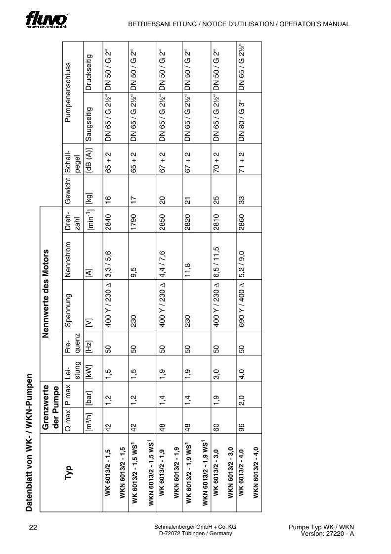
Dat
enb
latt
vo
n W
K-
/ WK
N-P
um
pen
Gre
nzw
erte
d
er P
um
pe
Nen
nw
erte
des
Mo
tors
Typ
Q m
axP
max
Lei-
stun
gFr
e-qu
enz
Spa
nnun
gN
enns
trom
Dre
h-za
hlG
ewic
htS
chal
l-pe
gel
Pum
pena
nsch
luss
[m³/
h][b
ar]
[kW
][H
z][V
][A
][m
in-1
][k
g][d
B (
A)]
Sau
gsei
tigD
ruck
seiti
g
WK
601
3/2
- 1,
5
WK
N 6
013/
2 -
1,5
421,
21,
550
400
Y /
230
∆3,
3 / 5
,628
4016
65 +
2D
N 6
5 / G
2½
“D
N 5
0 / G
2“
WK
601
3/2
- 1,
5 W
S1
WK
N 6
013/
2 -
1,5
WS
1
421,
21,
550
230
9,5
1790
1765
+ 2
DN
65
/ G 2
½“
DN
50
/ G 2
“
WK
601
3/2
- 1,
9
WK
N 6
013/
2 -
1,9
481,
41,
950
400
Y /
230
∆4,
4 / 7
,628
5020
67 +
2D
N 6
5 / G
2½
“D
N 5
0 / G
2“
WK
601
3/2
- 1,
9 W
S1
WK
N 6
013/
2 -
1,9
WS
1
481,
41,
950
230
11,8
2820
2167
+ 2
DN
65
/ G 2
½“
DN
50
/ G 2
“
WK
601
3/2
- 3,
0
WK
N 6
013/
2 -
3,0
601,
93,
050
400
Y /
230
∆6,
5 / 1
1,5
2810
2570
+ 2
DN
65
/ G 2
½“
DN
50
/ G 2
“
WK
601
3/2
- 4,
0
WK
N 6
013/
2 -
4,0
962,
04,
050
690
Y /
400
∆5,
2 / 9
,028
6033
71 +
2D
N 8
0 / G
3“
DN
65
/ G 2
½“

23Pumpe Typ WK / WKNVersion: 27220 - A
Schmalenberger GmbH + Co. KG D-72072 Tübingen / Germany
BETRIEBSANLEITUNG / NOTICE D´UTILISATION / OPERATOR´S MANUAL
Fic
he
tech
niq
ue
des
po
mp
es W
K-
/ WK
N
Val
eurs
lim
ites
de
la p
om
pe
Val
eurs
no
min
ales
du
mo
teu
r
Typ
eQ
m
ax.
P
max
.P
uiss
ance
Fréq
uenc
eTe
nsio
nC
oura
nt
nom
inal
Vite
sse
de
rota
tion
Poi
dsN
ivea
u ac
oust
ique
Rac
cord
de
pom
pe
[m³/
h][b
ar]
[kW
][H
z][V
][A
][tr
/min
][k
g][d
B (
A)]
Côt
é as
pira
tion
Côt
é re
foul
emen
t
WK
601
3/2
- 1,
5
WK
N 6
013/
2 -
1,5
421,
21,
550
400
Y /
230
∆3,
3 / 5
,628
4016
65 +
2D
N 6
5 / G
2½
”D
N 5
0 / G
2”
WK
601
3/2
- 1,
5 W
S1
WK
N 6
013/
2 -
1,5
WS
1
421,
21,
550
230
9,5
1790
1765
+ 2
DN
65
/ G
2½”
DN
50
/ G 2
”
WK
601
3/2
- 1,
9
WK
N 6
013/
2 -
1,9
481,
41,
950
400
Y /
230
∆4,
4 / 7
,628
5020
67 +
2D
N 6
5 / G
2½
”D
N 5
0 / G
2”
WK
601
3/2
- 1,
9 W
S1
WK
N 6
013/
2 -
1,9
WS
1
481,
41,
950
230
11,8
2820
2167
+ 2
DN
65
/ G
2½”
DN
50
/ G 2
”
WK
601
3/2
- 3,
0
WK
N 6
013/
2 -
3,0
601,
93,
050
400
Y /
230
∆6,
5 / 1
1,5
2810
2570
+ 2
DN
65
/ G
2½”
DN
50
/ G 2
”
WK
601
3/2
- 4,
0
WK
N 6
013/
2 -
4,0
962,
04,
050
690
Y /
400
∆5,
2 / 9
,028
6033
71 +
2D
N 8
0 / G
3”
DN
65
/ G 2
½”
24 Pumpe Typ WK / WKNVersion: 27220 - A
Schmalenberger GmbH + Co. KG D-72072 Tübingen / Germany
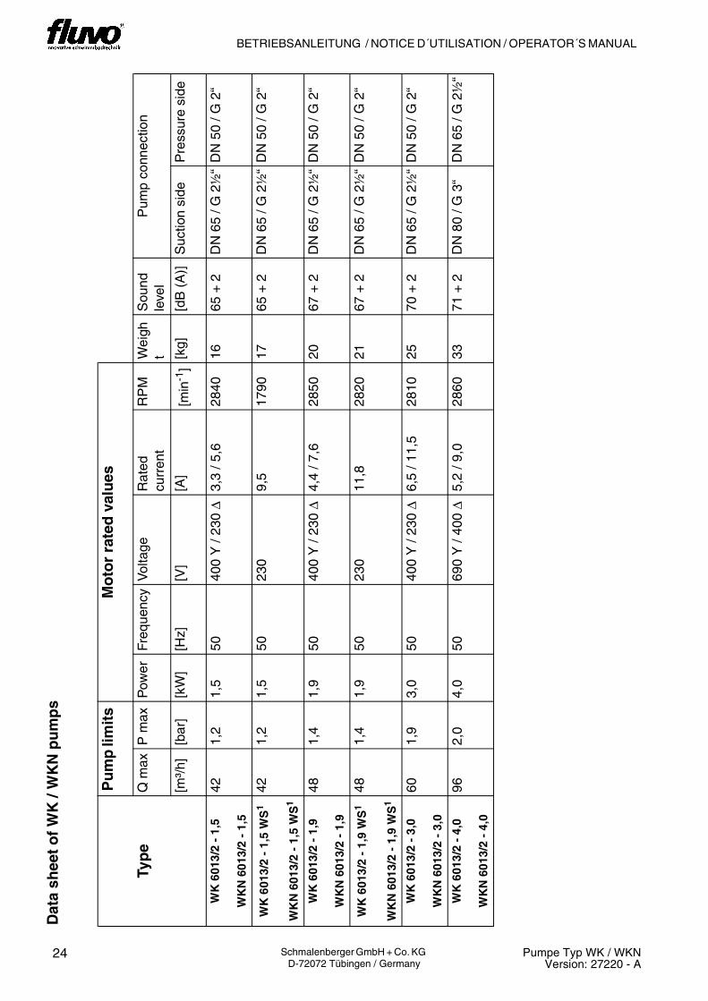
BETRIEBSANLEITUNG / NOTICE D´UTILISATION / OPERATOR´S MANUAL D
ata
shee
t o
f W
K /
WK
N p
um
ps
Pu
mp
lim
its
Mo
tor
rate
d v
alu
es
Typ
eQ
max
P m
axP
ower
Freq
uenc
yV
olta
geR
ated
cu
rren
tR
PM
Wei
ght
Sou
nd
leve
lP
ump
conn
ectio
n
[m³/
h][b
ar]
[kW
][H
z][V
][A
][m
in-1
][k
g][d
B (
A)]
Suc
tion
side
Pre
ssur
e si
de
WK
601
3/2
- 1,
5
WK
N 6
013/
2 -
1,5
421,
21,
550
400
Y /
230
∆3,
3 / 5
,628
4016
65 +
2D
N 6
5 / G
2½
“D
N 5
0 / G
2“
WK
601
3/2
- 1,
5 W
S1
WK
N 6
013/
2 -
1,5
WS
1
421,
21,
550
230
9,5
1790
1765
+ 2
DN
65
/ G 2
½“
DN
50
/ G 2
“
WK
601
3/2
- 1,
9
WK
N 6
013/
2 -
1,9
481,
41,
950
400
Y /
230
∆4,
4 / 7
,628
5020
67 +
2D
N 6
5 / G
2½
“D
N 5
0 / G
2“
WK
601
3/2
- 1,
9 W
S1
WK
N 6
013/
2 -
1,9
WS
1
481,
41,
950
230
11,8
2820
2167
+ 2
DN
65
/ G 2
½“
DN
50
/ G 2
“
WK
601
3/2
- 3,
0
WK
N 6
013/
2 -
3,0
601,
93,
050
400
Y /
230
∆6,
5 / 1
1,5
2810
2570
+ 2
DN
65
/ G 2
½“
DN
50
/ G 2
“
WK
601
3/2
- 4,
0
WK
N 6
013/
2 -
4,0
962,
04,
050
690
Y /
400
∆5,
2 / 9
,028
6033
71 +
2D
N 8
0 / G
3“
DN
65
/ G 2
½“

25Pumpe Typ WK / WKNVersion: 27220 - A
Schmalenberger GmbH + Co. KG D-72072 Tübingen / Germany
BETRIEBSANLEITUNG / NOTICE D´UTILISATION / OPERATOR´S MANUAL

BETRIEBSANLEITUNG
26 Pumpe Typ WK / WKNVersion: 27220 - A
Schmalenberger GmbH + Co. KG D-72072 Tübingen / Germany
2 Sicherheitshinweise2.1 Allgemeines
• Vergewissern Sie sich vor Inbetriebnahme, dass das Bedienungspersonal dieBetriebsanleitung gelesen und verstanden hat. Nicht der Bediener sondern derBetreiber ist für die Sicherheit verantwortlich!
• Sorgen Sie dafür, dass die in der Betreiberfirma und/oder dem Betreiberland für denEinsatz von Pumpen geltenden Sicherheitsvorschriften und Gesetze eingehalten wer-den.
• Alle mit dem Medium in Berührung kommende Teile sind bis zu einem absoluten Salz-gehalt von 0,75% (4500 mg/l Cl- ) beständig. Sollten höhere Salzkonzentrationen vor-liegen, muss Kontakt mit dem Hersteller aufgenommen werden.
• Benutzen Sie die Pumpe nur in technisch einwandfreiem Zustand, sowie bestim-mungsgemäß, sicherheits- und gefahrenbewusst, unter Beachtung aller Hinweise derBetriebsanleitung!
• Beseitigen Sie Störungen, die die Sicherheit beeinträchtigen können, umgehend.
2.2 Zeichen und Symbole
In dieser Betriebsanleitung warnen wir Sie durch entsprechende Hinweise vor Gefahren-quellen. Durch die Verwendung von Symbolen soll Ihre Aufmerksamkeit auf diese Hinwei-se gelenkt werden!
Symbol Bedeutung
Vorsicht! Verletzungsgefahr!Dieses Zeichen warnt Sie vor Gefahren durch mechanische Einwirkung.
Vorsicht! Lebensgefahr!
Dieses Zeichen warnt Sie vor Gefahren durch elektrischen Strom.
iWichtig:Dieses Zeichen warnt Sie vor Handlungen, die die Pumpe beschädigen oderzerstören. Es weist auch auf die wirtschaftliche Verwendung der Pumpe hin.

NOTICE D´UTILISATION
27Pumpe Typ WK / WKNVersion: 27220 - A
Schmalenberger GmbH + Co. KG D-72072 Tübingen / Germany
2 Consignes de sécurité2.1 Généralités
• Avant la mise en route, assurez-vous que le personnel de service a lu et comprisla notice d’utilisation. Ce n’est pas le personnel de service mais l’exploitant quiest responsable de la sécurité.
• Assurez-vous que les règlements de sécurité et les lois en vigueur concernantl’utilisation de soufflantes à canal latéral de la société exploitante et du pays danslequel l’exploitation a lieu soient respectés.
• Toutes les pièces entrant en contact avec le fluide sont résistantes jusqu’à une teneurabsolue en sel de 0,75% (4500 mg/l Cl- ). En cas de concentrations salines plusélevées, contacter le constructeur.
• N’utiliser la pompe que dans un état technique impeccable, conformément auxspécifications, en conscience de la sécurité et des risques- et en respectant toutes lesinformations fournies dans cette notice d’utilisation !
• Immédiatement procéder à la résolution des défauts qui pourrait avoir une influence
négative sur la sécurité.
2.2 Signes et symboles
Nous vous prévenons avec des indications appropriées des sources de dangerpotentielles dans cette notice d’utilisation. L’utilisation de symboles est destinée à attirervotre attention sur ces avertissements.
Symbole Signification
Attention! Danger de blessure!Ce pictogramme met en garde contre les dangers d’origine mécanique.
Prudence ! Danger de mort!
Ce pictogramme met en garde contre les dangers d’origine électrique.
iIndication:Ce pictogramme met en garde contre les activités entraînantl’endommagement ou la destruction de la pompe. Il attire aussi l’attention surl’utilisation rentable de la pompe.

OPERATOR’S MANUAL
28 Pumpe Typ WK / WKNVersion: 27220 - A
Schmalenberger GmbH + Co. KG D-72072 Tübingen / Germany
2 Safety Instructions2.1 General
• Prior to starting up, make sure that the operators have read and understood theoperator’s manual. Not the operator but the owner is responsible for safety!
• Make sure that the relevant safety regulations and laws are observed in the operatingcompany and / or country where the pumps are to be used.
• All parts that come into contact with the medium are resistant to an absolute saltcontent of up to 0.75% (4,500 mg/l Cl¯). If the salt concentrations are greater than this,the manufacturer must be consulted.
• Use the pump only if it is in perfect technical condition, in accordance with theregulations, observing safety requirements and danger conditions and strictly adheringto all the instructions in the operator’s manual!
• Promptly remedy any faults that could influence safety.
2.2 Signs and Symbols
In this operating manual the following symbols are used to draw your attention to sourcesof danger. The symbols are intended to attract your attention to these instructions!
Symbol Meaning
Attention! Danger of injury!This sign warns you of the danger of mechanical effects.
Warning! Mortal danger!
This sign warns you of the danger from electric shocks.
iInformation:This sign warns you of handling that could damage or destroy the pump. It alsoinstructs you in the economic use of the pump.

29Pumpe Typ WK / WKNVersion: 27220 - A
Schmalenberger GmbH + Co. KG D-72072 Tübingen / Germany
BETRIEBSANLEITUNG / NOTICE D´UTILISATION / OPERATOR´S MANUAL

BETRIEBSANLEITUNG
30 Pumpe Typ WK / WKNVersion: 27220 - A
Schmalenberger GmbH + Co. KG D-72072 Tübingen / Germany
2.3 Verpflichtung des Betreibers
• Direkt an der Pumpe angebrachte Hinweise, wie z.B. Drehrichtungspfeil und Kenn-zeichnung von Fluidanschlüssen, müssen unbedingt beachtet und in vollständig lesba-rem Zustand gehalten werden.
• Die Kreiselpumpe ist nach dem neuesten Stand der Technik und den anerkannten si-cherheitstechnischen Regeln gebaut. Dennoch können bei ihrer Verwendung Gefah-ren für Leib und Leben des Benutzers oder Dritter bzw. Beeinträchtigungen andererSachwerte entstehen.
• Der Betreiber / Bediener hat deshalb sorgfältig darauf zu achten, -dass die Betriebsanleitung dem Bedienungspersonal ständig zur Verfügung steht.-dass die Sicherheitshinweise in dieser Betriebsanleitung beachtet werden.
2.4 Sicherheitshinweise zur Aufstellung
• Die Kreiselpumpe ist zum Einbau in eine Gesamt-Maschine bzw. Anlage vorgesehen.Die Kreiselpumpe wird ohne Berührungsschutz geliefert. Evtl. erforderlicher Berüh-rungsschutz (z.B. bei Förderung heißer Flüssigkeiten über 60° C) muss vom Anlagen-hersteller bei der Integration der Kreiselpumpe in die Anlage vorgesehen werden.
• Beim Aufbau der Kreiselpumpe in einem Schacht muss dieser eine ausreichende Be-lüftung (Motorkühlung) und eine ausreichende Abflußmöglichkeit für Leckwasser (min-destens DN 40) haben.
2.5 Sicherheitshinweise zum Anschluss
• Elektrische Einrichtungen dürfen nur von Fachkräften installiert und gewartet werden.Dabei müssen die jeweils gültigen Sicherheitsbestimmungen und Einrichtungsvor-schriften am Einsatzort beachtet werden. Der Begriff Fachkraft ist in VDE 0105 undIEC364 definiert. Informationen für nicht qualifizierte Personen sind in dieser Betriebs-anleitung nicht enthalten. Wir weisen darauf hin, dass die Bestimmungen der EG denEinsatz von nichtqualifizierten Personen an elektrischen Anlagen verbietet.
• Arbeiten an elektrischen Ausrüstungen der Kreiselpumpe dürfen nur von einer Elektro-fachkraft oder von unterwiesenen Personen unter Leitung und Aufsicht einer Elektro-fachkraft gemäß den elektrotechnischen Regeln vorgenommen werden.
• Gefährdung durch elektrische Energie ist auszuschließen (Einzelheiten hierzu, siehein den landesspezifischen Vorschriften und/oder der örtlichen Energieversorgungs-unternehmen).
• Die Angaben auf dem Typenschild und die elektrischen Anschlussbedingungen müs-sen übereinstimmen.
• Es darf keine leitende Verbindung zwischen den metallischen Bauteilen des Motorsund dem Wasser bestehen.
• Die Kreiselpumpe darf nur über einen Fl-Schutzschalter betrieben werden.

NOTICE D´UTILISATION
31Pumpe Typ WK / WKNVersion: 27220 - A
Schmalenberger GmbH + Co. KG D-72072 Tübingen / Germany
2.3 Obligations de l’exploitant
• Respecter impérativement toutes les informations apposées directement sur la pompe,comme par ex. la flèche du sens de rotation et le repérage des raccords du fluide.Veiller à ce que ces informations soient toujours parfaitement lisibles.
• La pompe centrifuge a été construite conformément à l’état le plus récent de latechnique et aux règles techniques de sécurité reconnues. Le danger de blessurescorporelles voire mortelles pour l’utilisateur ou des tiers ou le risque de dégâtsmatériels dans leur environnement restent toujours existants lors de son utilisation.
• Il convient donc à l’exploitant / l’opérateur de veiller impérativement -à ce que le personnel opérateur dispose en permanence de la notice d’utilisation.-à ce que les consignes de sécurité figurant dans cette notice d’utilisation soientrespectées.
2.4 Consignes de sécurité concernant l’installation.
• La pompe centrifuge a été conçue pour un montage dans une machine voireinstallation globale. La pompe centrifuge est livrée sans protecteur anticontact. La miseen place de tout protecteur anticontact éventuellement requis (par ex. lors derefoulement de liquides brûlants supérieurs à 60° C) incombe au constructeur del’installation lors de l’intégration de la pompe centrifuge dans l’installation.
• Lors du montage de la pompe centrifuge dans un canal, celui-ci devra impérativementavoir une ventilation suffisante (refroidissement du moteur), tout comme une possibilitéd’écoulement suffisante pour l’eau de fuite (au moins DN 40).
2.5 Consignes de sécurité pour le raccordement
• Les dispositifs électriques doivent être installés et entretenus uniquement par dupersonnel spécialisé qualifié. Ce faisant, il doit respecter les réglementations desécurité et les directives d’installation en vigueur sur le lieu d’utilisation. La notion depersonnel spécialisé qualifié est définie dans les normes VDE 0105 et IEC364 ! Cettenotice d’utilisation n’inclut pas d’informations destinées à des personnes nonqualifiées. Nous soulignons que les réglementations de l’UE interdisent la mise enœuvre de personnels non qualifiés sur les installations électriques.
• L’exécution de travaux sur les équipements électriques est exclusivement réservée àun électricien qualifié ou à des personnes agissant sous la direction et la surveillanced’un électricien qualifié qui devra impérativement veiller au respect des règlesélectrotechniques..
• Tout danger dû à l’énergie électrique doit être écarté (voir pour cela les directivesnationales et/ou celles de la société d’alimentation.en énergie locale).
• Les données figurant sur la plaque de type et les conditions de raccordementélectriques doivent coïncider.
• Toute liaison à propriété conductible entre les éléments de construction métalliques dumoteur et l’eau est interdite.
• Le fonctionnement de la pompe centrifuge n’est autorisé que par le biais d’undéclencheur par courant de défaut.

OPERATOR’S MANUAL
32 Pumpe Typ WK / WKNVersion: 27220 - A
Schmalenberger GmbH + Co. KG D-72072 Tübingen / Germany
2.3 User Responsibilities
• Notices attached directly to the pump, e.g. arrows indicating direction of rotation andthe marking for fluid connections, must always be observed and maintained in a clearlylegible condition.
• The centrifugal pump has been built using state-of-the-art technology and incompliance with recognised safety regulations. Despite that there could be danger tolife and limb of the user or to third parties or damage to property in the way that youemploy the blower.
• So the owner / user must ensure that- the operator’s manual is always available for users to read.- the safety instructions in this operator's manual are carefully observed.
2.4 Safety Instructions for Installation
• The centrifugal pump is designed to be built into a total machine or plant. Thecentrifugal pump is delivered without any protection against accidental contact. Ifnecessary, the system supplier must fit appropriate protective covers in integrating thecentrifugal pump into the plant (e.g. if hot liquids with a temperature over 60° C aredelivered).
• If the centrifugal pump is built into a duct then it must be ensured that there is enoughventilation (for cooling the motor) and enough drainage facility for leaked water (at leastDN 40).
2.5 Safety Instructions for Connection
• Electrical equipment must be installed and maintained by qualified electricians. Theappropriate local safety requirements and installation regulations must be observed.The expression “qualified person” is defined in VDE 0105 and IEC364. There is noinformation contained in this operator’s manual for unqualified persons. It must bepointed out that EU regulations prohibit the use of unqualified persons on electricalsystems.
• Work on the electrical equipment of the centrifugal pump must be carried outexclusively by a qualified electrician or a person under the direct supervision of such aperson in accordance with electrical regulations.
• Danger from electric shocks must be completely excluded (for details see the countryspecific regulations and / or the local power supply company)
• The details on the type plate must correspond to the electrical supply being connectedto.
• Under no circumstances must there be any conducting connection between the metalparts of the motor and the water.
• The centrifugal pump may only be operated using an earth leakage circuit breaker.

33Pumpe Typ WK / WKNVersion: 27220 - A
Schmalenberger GmbH + Co. KG D-72072 Tübingen / Germany
BETRIEBSANLEITUNG / NOTICE D´UTILISATION / OPERATOR´S MANUAL

BETRIEBSANLEITUNG
34 Pumpe Typ WK / WKNVersion: 27220 - A
Schmalenberger GmbH + Co. KG D-72072 Tübingen / Germany
2.6 Sicherheitshinweise zur Inbetriebnahme
• Vor Einschalten/Inbetriebnahme der Kreiselpumpe sicherstellen, dass niemand durchdie anlaufende Kreiselpumpe gefährdet werden kann!
2.7 Sicherheitshinweise für den Betrieb
2.7.1 Temperatur
2.7.2 Leckageabfuhr
2.8 Sicherheitshinweise für Wartung und Reparaturarbeiten
• Reparaturen gleich welcher Art, sind nur von qualifiziertem Fachpersonal vorzuneh-men, dazu ist die Kreiselpumpe zu entleeren.
• Vor Reparaturen an der Pumpe ist diese elektrisch spannungsfrei zu schalten und ge-gen unbefugtes Wiedereinschalten zu sichern.
• Falls Flüssigkeiten gefördert werden, die in iorgendeiner Weise gesundheitsschädlicheWirkungen verursachen können, sind die benetzten Oberflächen der Pumpe vor Be-ginn jeglicher Arbeiten durch geeignete Maßnahmen (Spülen, Reinigen, Waschen) aufeinen Zustand zu bringen, der eine unbedenkliche Handhabung ermöglicht.
2.9 Sicherheitshinweise für die Ausserbetriebnahme
• Entleeren Sie die Kreiselpumpe.• Zur Überwinterung bauen Sie den Sendeknopf aus und lagern ihn bei Raumtempera-
tur.
!Wichtig:Die Kreiselpumpe muss sofort stillgesetzt werden, falls abnormale elektrischeSpannungen, Schwingungen, Temperaturen, Geräusche, Schwingungen, Un-dichtigkeiten oder andere Störungen auftreten.
Vorsicht! Verbrennungsgefahr!
Das Gehäuse der Kreiselpumpe erwärmt sich während des Betriebs. Wenndie Temperatur über +50°C ansteigt, muss die Kreiselpumpe vom Betreibervor direktem Berühren geschützt werden.
!Wichtig:Leckagen gefährlicher Fördergüter (z.B: explosiv, giftig, heiß) müssen so ab-geführt werden, dass keine Gefährdung für Personen und Umwelt entsteht.Gesetzliche Bestimmungen sind einzuhalten.

NOTICE D´UTILISATION
35Pumpe Typ WK / WKNVersion: 27220 - A
Schmalenberger GmbH + Co. KG D-72072 Tübingen / Germany
2.6 Consignes de sécurité pour la mise en service
• Avant la mise sous tension/la mise en service de la pompe centrifuge, s’assurer quepersonne ne pourra être menacé par le démarrage de la pompe centrifuge !
2.7 Consignes de sécurité pour l’exploitation
2.7.1 Température
2.7.2 Ecoulement des fuites
2.8 Consignes de sécurité pour l’entretien et les travaux de réparation.
• L’exécution de tous travaux de réparation, de quel type qu’ils soient, est exclusivementréservée à un personnel compétent qualifié qui devra pour cela procéder à la vidangede la pompe centrifuge.
• Avant de procéder aux réparations sur la pompe, couper l’alimentation électrique et laprotéger contre toute remise en route accidentelle.
• En cas de refoulement de liquides pouvant, quelle que soit la manière, avoir des effetsnéfastes sur la santé, traiter les surfaces arrosées de la pompe avant le début de toustravaux en prenant des mesures appropriées (rinçage, nettoyage, lavage) pour leurdonner un état permettant une manipulation exempte d’inconvénients.
2.9 Consignes de sécurité pour la mise hors service
• Vider la pompe centrifuge.• Pour la mise en hivernage, démonter la tête émettrice et l’entreposer à température
ambiante.
!Important:En cas d’anormalité de tensions électriques, de vibrations, de températures,de bruits, en cas de fuites et d’autres anomalies procéder impérativement àl’arrêt instantané de la pompe centrifuge.
Attention! Danger de brûlure !Le carter de la pompe centrifuge s’échauffe pendant le fonctionnement. Si latempérature dépasse +50°C, il convient à l’exploitant de doter la pompecentrifuge de protecteur anticontact.
!Important:L’écoulement des fuites de produits refoulés dangereux (par ex. : explosifs,toxiques, brûlants) doit impérativement être exécuté de sorte à ce qu’il ne soitune menace ni pour le personnel, ni pour l’environnement. Respecter lesdispositions légales.

OPERATOR’S MANUAL
36 Pumpe Typ WK / WKNVersion: 27220 - A
Schmalenberger GmbH + Co. KG D-72072 Tübingen / Germany
2.6 Safety Instructions for Start-up
• Before switching on or starting up the centrifugal pump, make sure that no-one will beendangered by the start-up of the pump!
2.7 Safety Instructions for Operation
2.7.1 Temperature
2.7.2 Leakage drainage
2.8 Safety Instructions for Maintenance and Repairs
• Regardless of what nature they may be, repairs must only be carried out by qualifiedpersons and the centrifugal pump must be emptied first.
• Prior to carrying out repairs the pump must be isolated from the electrical supply andprotected from unintentional switching on.
• If fluids are delivered that may result in any kind of effect that is hazardous to health,the moist surfaces of the pump must be subjected to appropriate measures (rinsing,cleaning, washing) to make handling them completely harmless before any kind of workis undertaken on the pump.
2.9 Safety information for shut-down
• Empty the centrifugal pump.• Over the winter, remove the transmission button and store it at room temperature.
!Important:The centrifugal pump must be immediately stopped if abnormal electricalvoltages, temperatures, noises, vibrations, leakages or other faults shouldarise.
Warning! Danger of burns!The centrifugal pump housing gets hot during operation. If the temperaturerises to over +50°C, the centrifugal pump must be protected from direct contactby the operator.
!Important:The leakage of dangerous delivery media (e.g. explosive, poisonous, hot)must be controlled so that no danger occurs to persons or the environment.Legal requirements must be adhered to.

37Pumpe Typ WK / WKNVersion: 27220 - A
Schmalenberger GmbH + Co. KG D-72072 Tübingen / Germany
BETRIEBSANLEITUNG / NOTICE D´UTILISATION / OPERATOR´S MANUAL

BETRIEBSANLEITUNG
38 Pumpe Typ WK / WKNVersion: 27220 - A
Schmalenberger GmbH + Co. KG D-72072 Tübingen / Germany
2.10 Potentielle Risikoquellen der Kreiselpumpe
• Kreiselpumpen sind nach dem neuesten Stand der Technik und den anerkannten si-cherheitstechnischen Regeln gebaut. Dennoch können bei ihrer Verwendung Gefah-ren für Leib und Leben des Benutzers oder Dritter bzw. Beeinträchtigungen andererSachwerte entstehen.
• Durch Funkwellen besonders gesundheitsgefährdete Personen (z.B: Träger von Herz-schrittmachern) sollten sich nicht in unmittelbarer Nähe der Pumpe Typ WKN mit Funk-ansteuerung aufhalten. In diesem Fall wird empfohlen, eine andere Ansteuerungsart(extern oder pneumatisch) zu wählen.
Ein Restrisiko bleibt aber immer bestehen!
Potentielle Gefahrenbereiche der Kreiselpumpe sind
• der Ansaugstutzen• der Ausblasstutzen• das Pumpengehäuse
Einzugsgefahr!
Am Ansaugstutzen kommt es zu starker Sogwirkung.
Stoßgefahr!
Am Ausblasstutzen können eingesogene Gegenstände mit hoher Geschwindigkeit her-ausgeschleudert werden.
Verbrennungsgefahr!
Das Gehäuse der Kreiselpumpe erwärmt sich während des Betriebs und muss daher vordirektem Zugriff geschützt werden.
Vorsicht! Verletzungsgefahr!Achten Sie auf anliegende Kleidung und Haare. Legen Sie Schmuckstücke vorder Arbeit ab.Greifen Sie nicht in den Ansaugstutzen hinein.
Vorsicht! Verletzungsgefahr!Schalten Sie der Kreiselpumpe einen Filter vor, der eingesogene Gegenstän-de oder Verunreinigungen herausfiltert.
Vorsicht! Verletzungsgefahr!Schützen Sie den Bediener vor Kontakt mit der Kreiselpumpe!Bringen Sie einen Berührungsschutz an.Lassen Sie die Kreiselpumpe abkühlen, ehe Sie mit Wartungs- und Repara-turabeiten beginnen.

NOTICE D´UTILISATION
39Pumpe Typ WK / WKNVersion: 27220 - A
Schmalenberger GmbH + Co. KG D-72072 Tübingen / Germany
2.10 Sources de risque potentielles de la pompe centrifuge
• Les pompes centrifuges ont été construites conformément à l’état le plus récent de latechnique et aux règles techniques de sécurité reconnues. Le danger de blessures cor-porelles voire mortelles pour l’utilisateur ou des tiers ou le risque de dégâts matérielsdans leur environnement restent toujours existants lors de leur utilisation.
• Nous recommandons à toute personne particulièrement menacée par les ondesradioélectriques (par ex. : des personnes portant un simulateur cardiaque) de ne passtationner à proximité immédiate de la pompe du type WKN à commande radio. Dansce cas, nous recommandons d’opter pour un autre type de commande (par ex. externeou pneumatique).
Il demeure toujours un risque résiduel.
Les points à risque potentiel de la pompe centrifuge sont
• La buse d’aspiration• La buse de soufflerie• Le carter de la pompe
Danger de happement !
Une grande force d’aspiration est exercée au niveau de la buse d’aspiration.
Danger de heurt !
Des objets ayant été aspirés peuvent être expulsés à haute vitesse au niveau de la bused’expulsion.
Danger de brûlure !
Le carter de la pompe centrifuge s’échauffant pendant le fonctionnement doit être de cefait protéger contre tout accès direct.
Attention! Danger de blessure!Faites attention à vos cheveux et aux vêtements amples. Enlevez vos bijouxavant de vous mettre au travail.Ne pas mettre les mains dans la buse d’aspiration.
Attention! Danger de blessure!Installer un filtre additionnel dans la pompe centrifuge, lequel aura pourfonction de filtrer tout objet ou toute impureté aspirés.
Attention! Danger de blessure!Protéger l’opérateur contre tout contact avec la pompe centrifuge !Montez une protection contre les contacts.Laisser la pompe centrifuge refroidir avant d’entamer les travaux d’entretien etde réparation.

OPERATOR’S MANUAL
40 Pumpe Typ WK / WKNVersion: 27220 - A
Schmalenberger GmbH + Co. KG D-72072 Tübingen / Germany
2.10 Potential Sources of Risk with the Centrifugal Pump
• Centrifugal pumps have been built using state-of-the-art technology and in compliancewith recognised safety regulations. Despite that there could be danger to life and limbof the user or to third parties or damage to property in the way that you employ the blo-wer.
• Persons who are likely to be endangered by radio waves (e.g. wearers of heartpacemakers) should not linger near pump type WKN with radio control. In this case itis recommended to choose a different type of control, such as external or pneumatic.
It is impossible to eliminate all potential risks!
Potential danger areas on the centrifugal pump are:
• the suction inlet• the blow-out nozzle• the pump housing.
Danger of getting drawn in!
There is strong suction at the suction inlet.
Danger of impact!
At the blow-out nozzle objects that were sucked in may be expelled at high speed.
Danger of burns!
The centrifugal pump housing gets hot during operation and must be protected from directcontact..
Attention! Danger of injury!Watch your loose clothing and hair. Remove jewellery before operating theblower.Never put your hands into the suction inlet.
Attention! Danger of injury!Place a filter in front of the centrifugal pump that removes objects andimpurities before they can be drawn in.
Attention! Danger of injury!Ensure that the operator does not touch the centrifugal pump!Fix a protective cover to the unit.Allow the centrifugal pump to cool down before you carry out maintenance orrepair work.

41Pumpe Typ WK / WKNVersion: 27220 - A
Schmalenberger GmbH + Co. KG D-72072 Tübingen / Germany
BETRIEBSANLEITUNG / NOTICE D´UTILISATION / OPERATOR´S MANUAL

BETRIEBSANLEITUNG
42 Pumpe Typ WK / WKNVersion: 27220 - A
Schmalenberger GmbH + Co. KG D-72072 Tübingen / Germany
NOTICE D´UTILISATION
Elektrische Ausrüstung
2.11 Gerätebeschreibung
• Die Pumpe entspricht den VDE-Vorschriften.
• Der Elektromotor und die wasserführende Kunststoffpumpe sind elektrisch getrennt.
• Der Elektromotor entspricht der Schutzart IP 54.
• Die Kreiselpumpe insgesamt entspricht der Schutzklasse I.
Vorsicht! Elektrische Spannung!Arbeiten an der elektrischen Ausrüstung dürfen nur von entsprechend ausge-bildetem Fachpersonal den elektrotechnischen Regeln entsprechend durch-geführt werden.
Equipement électrique
2.11 Descriptif de l’appareil
• La pompe répond aux prescriptions VDE (Association allemande de l'ingénerieélectrique, association déclarée).
• Le moteur électrique et la pompe plastique conductrice d’eau sont électriquementséparés.
• Le moteur électrique correspond au type de protection IP 54.
• La pompe centrifuge correspond au total à la classe de protection I.
Attention! Tension électrique!Les travaux sur les équipements électriques doivent être réalisés uniquementpar un personnel ayant reçu la formation adéquate dans le respect des règlesélectrotechniques.

43Pumpe Typ WK / WKNVersion: 27220 - A
Schmalenberger GmbH + Co. KG D-72072 Tübingen / Germany
OPERATOR´S MANUAL
Electrical Equipment
2.11 Description of the Unit
• The pump complies with VDE (Association for Electrical, Electroic & InformationTechnologies) regulations.
• The electric motor and the water conducting plastic pump are electrically separated.
• The electric motor complies with protection class IP 54.
• The entire centrifugal pump complies with protection class I.
Warning! High Voltage!Only qualified electricians must be allowed to work on the electrical equipment.

44 Pumpe Typ WK / WKNVersion: 27220 - A
Schmalenberger GmbH + Co. KG D-72072 Tübingen / Germany
BETRIEBSANLEITUNG / NOTICE D´UTILISATION / OPERATOR´S MANUAL
3 Transport, Lagerung, Montage3.1 Transport und Lagerung
3.1.1 Transport
Abb. 3: Anschlagbeispiel
!Wichtig:Kreiselpumpen sind liegend zu transportieren!
iHinweis:Die Tragösen am Motor sind nur für das Gewicht des Motors allein ausgelegt.Ein aus Motor und Kreiselpumpe bestehendes Pumpenaggregat muss zumAnheben sowohl motor- als auch pumpenseitig angehängt sein! Falls erforder-lich ist an der Pumpe selbst und auf der Verpackung die Schwerpunktlage ge-kennzeichnet und die Stellen für das Einhängen der Hebevorrichtung markiert.
Vorsicht! Verletzungsgefahr!Nur geeignete und technisch einwandfreie Hebezeuge sowie Lastaufnahme-mittel mit ausreichender Tragkraft verwenden!Nicht unter schwebenden Lasten aufhalten oder arbeiten!
38118

OPERATOR´S MANUALNOTICE D´UTILISATION
45Pumpe Typ WK / WKNVersion: 27220 - A
Schmalenberger GmbH + Co. KG D-72072 Tübingen / Germany
3 Transport, entreposage, montage3.1 Transport et entreposage
3.1.1 Transport
Fig. 3: Exemple de suspension
!Important:Transporter les pompes centrifuges à l’horizontale !
iIndication:Les œillets de transport sur le moteur ne sont prévus que pour le poids du moteur.Un groupe moto-pompe composé du moteur et de la pompe centrifuge doit êtresuspendu pour le soulèvement aussi bien du côté moteur que du côté pompe ! Sinécessaire, la position du centre de gravité est repérée sur la pompe même et surl’emballage et les points d’accrochage du dispositif de levage sont marqués.
Attention! Danger de blessure!Seuls des dispositifs de levage appropriés, en parfait état technique et avec unecapacité de levage suffisante doivent être utilisés !Ni stationner, ni travailler sous des charges en suspension !
3 Transport, Storage, Installation3.1 Transport and Storage
3.1.1 Transport
Fig. 3: Lifting example
!Important:Centrifugal pumps must be transported lying down!
iInformation:The eyebolts on the motor are designed to carry only the weight of the motor. Tolift the combined motor and centrifugal pump aggregate suitable attachmentsmust be made so that both units are catered for! If necessary the centre of massis indicated on the pump aggregate and on the packing material and places forapplying hooks are marked.
Attention! Danger of injury!Use only suitable and technically perfect lifting and load-bearing equipment withsufficient carrying power!Never stand or work underneath swinging loads!

46 Pumpe Typ WK / WKNVersion: 27220 - A
Schmalenberger GmbH + Co. KG D-72072 Tübingen / Germany
BETRIEBSANLEITUNG / NOTICE D´UTILISATION / OPERATOR´S MANUAL
3.1.2 Lagerung
• ZwischenlagerungSelbst bei kurzzeitiger Zwischenlagerung trocken, gut belüftet und erschütterungsfrei aufHolzunterlagen bei möglichst konstanter Temperatur lagern.• Ungünstige LagerungLiegen ungünstige Lagerungsbedingungen vor (z.B. hohe Luftfeuchtigkeit), oder wird dieKreiselpumpe länger als 6 Wochen auf Lager liegen, dann ist das Gehäuse der Kreisel-pumpe mit Öl zu füllen (siehe 2.1.).• Lange LagerdauerBei einer Lagerzeit von mehr als 2 Jahren müssen die Wälzlager im Motor neu gefettetoder komplett erneuert werden.
3.1.2 Entreposage
• EntreposageEntreposer dans un endroit sec, aéré et à l’abri des vibrations sur des structures en bois,avec, si possible, une température constante, y compris pour de courtes périodes.• Mauvais entreposageEn cas de conditions de entreposage défavorables (par ex. humidité d’air élevée), ou dedurée de entreposage de la pompe centrifuge supérieure à 6 semaines, remplir alors lecarter de la pompe centrifuge d’huile (voir 2.1.).• Longue durée d’entreposageAvec une durée d’entreposage supérieure à deux ans, les paliers de laminoir et le moteurdoivent être de nouveau graissés ou remplacés.
3.1.2 Storage
• Interim storageEven for short periods of interim storage, store on a wooden base in a dry, well ventilatedand vibration free environment at constant temperature.• Unsuitable storageIf unsuitable storage conditions prevail (e.g. high humidity) or if the centrifugal pump is tobe stored for longer than 6 weeks, then the centrifugal pump housing should be filled withoil (see 2.1).• Long periods of storageAfter a storage period of more than 2 years the motor roller bearings need to be re-greasedor replaced entirely.

47Pumpe Typ WK / WKNVersion: 27220 - A
Schmalenberger GmbH + Co. KG D-72072 Tübingen / Germany
BETRIEBSANLEITUNG / NOTICE D´UTILISATION / OPERATOR´S MANUAL
3.1.3 Conservation
The centrifugal pumps that we deliver are treated with a conservation materialcorresponding to the storage time quoted us by the purchaser. This conservation must beremoved before start-up. See chapter 3.2.2 “Cleaning”.If the centrifugal pump is to be taken out of service for a longer period of time or if theoriginally envisaged storage time is going to be considerably exceeded, then conservationmust be undertaken as protection against corrosion. How to do this is described in detail in chapter 10.1 “Shutdown / Storage / Conservation”.
3.1.3 Konservierung
Die von uns gelieferten Kreiselpumpen werden entsprechend der vom Besteller angege-benen Lagerzeit mit einer Konservierung versehen. Diese Konservierung ist vor Inbetrieb-nahme zu entfernen, siehe dazu Kapitel 3.2.2 „Reinigen“.Wird die Kreiselpumpe längere Zeit außer Betrieb genommen, oder wird die ursprünglichvorgesehene Lagerzeit vor der Inbetriebnahme erheblich überschritten, ist als Korrosions-schutz eine Konservierung vorzunehmen. Wie Sie dabei vorgehen wird in Kapitel 10.1 „Außerbetriebnahme / Einlagerung / Konser-vierung“ genau beschrieben.
3.1.3 Conservation
Les pompes centrifuges que nous avons livrées sont pourvues d’une conservationappropriée à la durée de entreposage indiquée par l’exploitant. Cette conservation doitêtre retirée avant la mise en service, voir pour cela le chapitre 3.2.2 « nettoyage »Si la durée de mise hors service de la pompe centrifuge est prolongée ou si elle dépassela durée de entreposage prévue à l’origine, doter la pompe centrifuge d’une coucheanticorrosion servant de moyen de conservation. La marche à suivre est décrite précisément dans le chapitre 10.1 « mise hors service /entreposage / conservation ».
BETRIEBSANLEITUNG
48 Pumpe Typ WK / WKNVersion: 27220 - A
Schmalenberger GmbH + Co. KG D-72072 Tübingen / Germany
3.2 Auspacken, Reinigung und Zusammenbau
3.2.1 Auspacken
Die Kreiselpumpe ist zum Transport auf einer Palette mit Bändern fixiert. Zum Transportüber lange Wege ist sie in Verschläge oder Kisten verpackt. Nach dem Lösen der Haltebänder die Kreiselpumpe mit entsprechendem Hilfsmittel (He-bezeug) aus der Verpackung heben.
3.2.2 Reinigen
Zum Schutz vor Transportschäden oder Korrosion sind verschiedene Maßnahmen vorge-sehen. Überzeugen Sie sich an Ihrer Kreiselpumpe, welche hier vorhanden sind.1. Abschlussdeckel an den Stutzen2. Wellenschutz, bei Lieferung ohne Motor3. Schutzlack an blanken TeilenVor dem Aufstellen bzw. der Montage der Kreiselpumpe sind diese Schutzvorrichtungenzu entfernen.
!Wichtig:Im Inneren der Kreiselpumpe dürfen keine Verunreinigungen zurückbleiben!Je nach Fördermedium ist das Innere der Kreiselpumpe von Ölrückständen zureinigen. Verwenden Sie dazu ein Reinigungsmittel. das die Gleitringdichtungund den Pumpenwerkstoff nicht beschädigt.Achten Sie darauf, dass die Pumpe nach dem Reinigen sorgfältig getrocknetwirdAls Reinigungsmittel kann z.B. Spiritus, Ritzol 155 oder eine stark alkalischeSeifenlauge verwendet werden. Bei der Verwendung von Dampfstrahlreini-gern das Lösungsmittel vorher einwirken lassen.Verwenden Sie nach Möglichkeit keinen Dampfstrahlreiniger. Wenn doch,achten Sie bei der Verwendung darauf, den Elektromotor und die Lagerungennicht zu beschädigen.

NOTICE D´UTILISATION
49Pumpe Typ WK / WKNVersion: 27220 - A
Schmalenberger GmbH + Co. KG D-72072 Tübingen / Germany
3.2 Déballage, nettoyage et montage
3.2.1 Déballage
Pour le transport sur une palette, la pompe centrifuge est fixée au moyen de bandes. Pourle transport sur de plus longs trajets, elle est emballée dans des caisses à claire-voie oudes caisses. Après avoir détaché les bandes de retenue, soulever la pompe centrifuge au moyen d’unengin de levage approprié pour la sortir de l’emballage.
3.2.2 Nettoyage
Divers protecteurs ont été prévus pour la protection contre les dommages dus au transportet contre la corrosion. Inspecter votre pompe centrifuge pour savoir ceux qui ont étéutilisés ici.1. Couvercle de bouchage au niveau des buses.2. Protection contre les ondes lors de livraisons sans moteur3. Peinture protectrice sur les pièces à fini brillant.Avant la mise en place, voire le montage de la pompe centrifuge, enlever ces dispositifsde protection.
!Important:Aucune impureté ne doit rester à l’intérieur de la pompe centrifuge !Nettoyer les résidus d’huile à l’intérieur de la pompe centrifuge en fonction dufluide refoulé. Utiliser à cette fin un agent de nettoyage qui n’endommagera nile joint mécanique, ni le matériau de la pompe.Veiller à ce que la pompe soit méticuleusement séchée après le nettoyageL’agent de nettoyage utilisé peut être par ex. de l’alcool, Ritzol 155 ou unelessive de savon fortement alcaline. Lors de l’utilisation de nettoyeurs au jet devapeur, laisser agir auparavant le solvant.Dans la mesure du possible, ne pas utiliser de nettoyeur au jet de vapeur. Sivous y êtes obligé, veiller à ne pas endommager le moteur électrique et lespaliers.
OPERATOR’S MANUAL
50 Pumpe Typ WK / WKNVersion: 27220 - A
Schmalenberger GmbH + Co. KG D-72072 Tübingen / Germany
3.2 Unpacking, Cleaning and Assembling
3.2.1 Unpacking
For transportation purposes the centrifugal pump is fastened to a palette by bands. Fortransportation over long distances it is packed in crates or boxes . After removing the retaining bands extract the centrifugal pump out of its packing with thehelp of suitable lifting equipment.
3.2.2 Cleaning
A number of measures are taken for protection against transportation damage andcorrosion. Check your centrifugal pump for which measures have been taken.1. Covering lid on the nozzles2. Shaft protection for deliveries without the motor3. Protective paint on exposed partsThese protective measures must be removed before the centrifugal pump is set up orinstalled.
!Important:Under no circumstances must impurities be left inside the centrifugal pump.Depending on the delivery medium to be used, the interior of the centrifugalpump should be cleaned of residual traces of oil. Use a cleaning agent that willnot be harmful to the mechanical seal and the pump materials. Make sure that the pump is carefully dried after cleaning.The cleaning agents that can be used include spirit, Ritzol 155 or a stronglyalkaline soap solution, for example. If a steam jet cleaner is to be used, thenlet the solvent work itself in for a time first. Please do not use a steam jet cleaner. If this is unavoidable, then please takecare not to damage the electric motor and bearings.

51Pumpe Typ WK / WKNVersion: 27220 - A
Schmalenberger GmbH + Co. KG D-72072 Tübingen / Germany
BETRIEBSANLEITUNG / NOTICE D´UTILISATION / OPERATOR´S MANUAL

52 Pumpe Typ WK / WKNVersion: 27220 - A
Schmalenberger GmbH + Co. KG D-72072 Tübingen / Germany
BETRIEBSANLEITUNG / NOTICE D´UTILISATION / OPERATOR´S MANUAL
3.2.3 Zusammenbau
Die Kreiselpumpe wird i.d.R. vormontiert geliefert und ist damit einbaufertigIn Sonderfällen ist die Kreiselpumpe ohne Antriebsmotor geliefert worden. Bauen Sie denAntrieb an die Kreiselpumpe, ehe sie in die Anlage montiert wird..
iHinweis:Kontrollieren Sie den leichten Lauf der Kreiselpumpe und ihre Freigängigkeitvor Beginn der Montage.Sonstiges externes Zubehör wie z. B. Windkessel o.ä., die nicht werksseitig ander Kreiselpumpe vormontiert sind, sollten erst nach der Montage der Kreisel-pumpe in die Anlage oder auf dem Fundament der Kreiselpumpe angebautwerden.
3.2.3 Montage
En principe, la pompe centrifuge est livrée prémontée et est de ce fait prête au montageDans des cas spéciaux, la pompe centrifuge est livrée sans moteur d’entraînement.Monter l’entraînement sur la pompe centrifuge avant d’intégrer cette dernière dansl’installation..
iIndication:Avant le début du montage de la pompe centrifuge, contrôler si sa marche estlibre et si la liberté de mouvement est assurée.En ce qui concerne d’autres accessoires externes, comme par ex. le réservoird’air ou autres accessoires similaires, qui n’ont pas été prémontés sur lapompe centrifuge à l’usine du constructeur, il est conseillé de ne les monterqu’après le montage de la pompe centrifuge dans l’installation ou sur lafondation de la pompe centrifuge.
3.2.3 Assembling
In general the centrifugal pump is delivered fully assembled and can be installed directly.In special cases the centrifugal pump is delivered without the drive motor. If so, then fit thedrive to the centrifugal pump before it is installed in the plant.
iInformation: Before installation check that the centrifugal pump runs freely and easily.Other external accessories such as a blast tank or similar equipment that hasnot been assembled with the centrifugal pump at the factory, should bemounted on the centrifugal pump after it has been installed in the system or onthe centrifugal pump base.
53Pumpe Typ WK / WKNVersion: 27220 - A
Schmalenberger GmbH + Co. KG D-72072 Tübingen / Germany
BETRIEBSANLEITUNG / NOTICE D´UTILISATION / OPERATOR´S MANUAL
3.3 Installation et raccordement
Protection Ex / consignes de sécurité
Les outils de production électriques, qui sont exploités dans des zones àdanger explosif, doivent répondre aux normes de protection Ex. Cela estindiqué par la plaque de fabrication du moteur.Lors de l’installation dans des zones à danger explosif, les règlements Exlocaux en vigueur et les directives de la fiche de contrôle jointe, rédigée parl’autorité de contrôle habilitée, doivent être respectés.La fiche de contrôle jointe doit être conservée sur le lieu de mise en œuvre (parex. bureau du contremaître).
3.3 Aufstellen und Anschließen
Ex Schutz / Sicherheitshinweis
Elektrische Betriebsmittel, die in explosionsgefährdeten Bereichen betriebenwerden, müssen die Ex-Schutz-Bestimmungen erfüllen. Dies wird durch dasFabrikschild des Motors ausgewiesen.Bei Aufstellung in explosionsgefährdeten Bereichen müssen die örtlich gelten-den Ex-Vorschriften und die Vorschriften des mitgelieferten Prüfscheines, derdurch die zuständige Prüfbehörde ausgestellt worden ist, beachtet und einge-halten werden.Der mitgelieferte Prüfschein ist am Einsatzort (z.B. Meisterbüro etc.) aufzube-wahren.
3.3 Installing and Connecting
Explosion proof / safety instructions
Electrical appliances that are operated in areas where there is a danger ofexplosion, must comply with the explosion proof requirements. This is statedon the factory plate of the motor.For installations in areas where there is a danger of explosion, the localexplosion regulations and those on the test certificate supplied with thedelivery, and which was issued by the responsible inspection authority, mustbe observed.The test certificate supplied must be kept at the installation location (e.g. themaster’s office).

54 Pumpe Typ WK / WKNVersion: 27220 - A
Schmalenberger GmbH + Co. KG D-72072 Tübingen / Germany
BETRIEBSANLEITUNG / NOTICE D´UTILISATION / OPERATOR´S MANUAL
3.3.1 Vérifier avant le début de l’installation
• La machine / l’installation / le support de récipient sont-ils préparés selon lesdimensions de la fiche de mesures / du plan d’installation ?
• Les fondements en béton ont-ils une résistance suffisante (min. B15) selonDIN 1045 ?
• Le fondement en béton est-il pris ? • La surface est-elle plane et horizontale ?
Attention! Danger de blessure!Veiller à la stabilité du positionnement !Les pompes à gros entraînements montées à la verticale sont trop lourdes duhaut. Caler de telles pompes pendant le montage, voire le démontage, par ex.à l’aide de câbles de retenue.
3.3.1 Überprüfen Sie vor Aufstellungsbeginn
• Ist die Maschine / die Anlage / der Behälterstutzen gemäß den Abmessungen desMaßblattes / Aufstellungsplanes vorbereitet?
• Haben die Betonfundamente die ausreichende Betonfestigkeit (min. B 15) nachDIN 1045 ?
• Ist das Betonfundament abgebunden? • Ist die Oberfläche waagerecht und eben?
Vorsicht! Verletzungsgefahr!Achten Sie auf Standsicherheit!Pumpen mit großen Antrieben, die senkrecht eingebaut werden, sind kopfla-stig. Diese Pumpen sind während der Montage bzw. Demontage gegen Kip-pen zu sichern, z.B. mit Hilfe von Halteseilen.
3.3.1 Check before you start installing
• Have the machine, the system and the container nozzles been properly prepared inaccordance with the figures on the dimensions sheet or installation plan?
• Has the concrete base got adequate strength (minimum of B 15) in accordance withDIN 1045 ?
• Is the concrete base hydrated? • Is the surface level and even?
Attention! Danger of injury!Please ensure that there is static stability!Pumps with large drives that are mounted vertically are top heavy. Thesepumps must be safeguarded against tipping up during installation or removale.g. with the help of ropes.

BETRIEBSANLEITUNG
55Pumpe Typ WK / WKNVersion: 27220 - A
Schmalenberger GmbH + Co. KG D-72072 Tübingen / Germany
3.3.2 Ein- und Aufbau der Kreiselpumpe
Die Kreiselpumpen werden, ausser in Sonderausführungen, immer mit Pumpenfuß oderdem Motorfuß auf eine Grundplatte gestellt und mit Schrauben befestigt.Bei der Montage auf ein Fundament ist die Kreiselpumpe, mit Hilfe einer Wasserwaage,auszurichten.
3.3.3 Anschließen der Rohrleitungen
• Bei kurzen Rohrleitungen sollen die Nennweiten mindestens denen der Pumpenan-schlüsse entsprechen. Bei langen Rohrleitungen ist die wirtschaftlichste Nennweitevon Fall zu Fall zu ermitteln.
• Übergangsstücke auf größere Nennweiten sollten mit ca. 8º Erweiterungswinkel aus-geführt werden, um erhöhte Druckverluste zu vermeiden.
• Die Saugleitung ist zur Kreiselpumpe kontinuierlich steigend, bei Zulauf kontinuierlichfallend zu verlegen, um Luftsackbildung zu vermeiden.
• Der Einbau von Rückflußverhinderern und Absperrorganen ist, je nach Art der Anlageund der Kreiselpumpe, zu empfehlen.
• Durch Temperatur entstehende Ausdehnungen der Rohrleitungen müssen durch ge-eignete Maßnahmen abgefangen werden. Wir empfehlen, Kompensatoren unmittelbarzwischen Kreiselpumpe und Rohrleitung einzubauen.
iHinweis:Die Kreiselpumpe darf auf keinen Fall als Festpunkt für die Rohrleitung ver-wendet werden. Vom Rohrleitungssystem dürfen keine Kräfte und Momente(z.B. durch Verwindung, Wärmeausdehnung) auf die Kreiselpumpe wirken.Die Rohre sind unmittelbar vor der Pumpe abzufangen und spannungsfrei an-zuschließen. Das sollte unter Verwendung geeigneter Kompensatoren ge-schehen.
Achtung:Lebensgefahr! Bei heißen, ätzenden und giftigen Fördermedien!Bei Überschreitung der Rohrleitungskräfte können, z.B. undichte Stellen ander Kreiselpumpe selbst oder an den Flanschverbindungen entstehen, diezum heftigen Austritt von Fördermedium führen.

NOTICE D’UTILISATION
56 Pumpe Typ WK / WKNVersion: 27220 - A
Schmalenberger GmbH + Co. KG D-72072 Tübingen / Germany
3.3.2 Montage intégré et montage sur fondation de la pompe centrifuge
A l’exception des modèles spéciaux, les pompes centrifuges sont toujours posées, puisfixées au moyen de vis sur une plaque de fond par le pied de la pompe ou le pied dumoteur.Lors de montage sur une fondation, aligner la pompe centrifuge au moyen d’un niveau àbulles.
3.3.3 Raccordement des conduites
• Dans le cas de conduites courtes, les sections nominales de passage doivent au moinscorrespondre à celles des raccords de pompe. Dans le cas de conduites longues,déterminer la section nominale de passage la plus rentable de cas en cas.
• Il est recommandé d’exécuter les éléments de transition sur de plus grandes sectionsnominales de passage avec un évasement d’au moins 8º environ pour éviter despertes de pression accrues.
• En direction de la pompe centrifuge poser la conduite d’aspiration en montant encontinu et en descendant en continu en direction de l’amenée pour éviter touteformation de poches d’air.
• Selon le type de l’installation et de la pompe centrifuge, il est conseillé de monter desclapets antiretour et des organes d’arrêt.
• La dilatation des conduites provoquée par la température doit être compensée par desmesures appropriées. Nous préconisons le montage de compensateurs entre lapompe centrifuge et la tuyauterie.
iIndication:Il est formellement interdit d’utiliser la pompe centrifuge en tant que point fixepour la tuyauterie. Aucune force et aucun couple (par ex. par le biais detorsion, dilatation thermique) ne doit agir sur la pompe centrifuge depuis lesystème de tuyauterie. Arrêter les tuyaux juste devant la pompe et lesraccorder sans tension. Cela doit être effectué en utilisant des compensateursappropriés.
Attention:Danger de mort ! En cas de fluides refoulés brûlants, corrosifs et toxiques !En cas de dépassement des forces de la tuyauterie il est possible que par ex.des points non étanches sur la pompe centrifuge même ou sur les jonctionsbridées apparaissent et provoquent alors un échappement violent du fluiderefoulé.
OPERATOR’S MANUAL
57Pumpe Typ WK / WKNVersion: 27220 - A
Schmalenberger GmbH + Co. KG D-72072 Tübingen / Germany
3.3.2 Installing and Erecting the Centrifugal Pump
Except in the case of special models, centrifugal pumps are always placed with the pumpfoot or motor foot onto a base plate and are fastened down with screws. When installed on a foundation the centrifugal pump must be set up with the aid of a spiritlevel.
3.3.3 Connecting the Pipework
• In the case of short pipes the nominal bore should be at least the same as thecentrifugal pump connections. For long pipes the most economic nominal bore shouldbe determined on a case by case basis.
• Connection pieces to larger nominal bores should be carried out with approx. 8°expansion angle to avoid significant loss of pressure.
• In order to prevent the formation of air pockets, the suction pipe to the centrifugal pumpmust be installed to rise continuously, on the pressure side it must fall continuously.
• Depending on the type of system and centrifugal pump being used, it is recommendedthat backflow prevention and shut-off devices are installed.
• Expansion of the pipes due to temperature must be remedied by suitable measures.We recommend the installation of compensators immediately between the centrifugalpump and the pipes.
iInformation:Under no circumstances must the centrifugal pump be used as anchor point forthe pipework. No forces or moments (e.g. due to twisting or heat expansion)from the pipework must act on the centrifugal pump. The pipes must besupported as close as possible to the centrifugal pump and connected to it freeof all tension. This should be done by using suitable compensators.
Attention:Mortal danger! In the case of hot, caustic or poisonous delivery media!If the pipe strength is exceeded leaks can occur in the centrifugal pump or inthe flange connections, for example, that could result in vast amounts ofmedium being expelled.

BETRIEBSANLEITUNG
58 Pumpe Typ WK / WKNVersion: 27220 - A
Schmalenberger GmbH + Co. KG D-72072 Tübingen / Germany
4 Elektrischer Anschluss4.1 Elektrischer Anschluss allgemein
Lassen Sie den elektrischen Anschluss der Kreiselpumpe durch einen vom zuständigenEnergieversorger zugelassenen Fachbetrieb des Elektrohandwerks, unter Berücksichti-gung der technischen Anschlussbedingungen, durchführen.
Beachten Sie:
• Der Netzanschluß darf nur über einen Festanschluss erfolgen.• Es darf keine leitende Verbindung von metallischen Bauteilen des Motors zum Wasser
bestehen.• In der Netzzuleitung muss ein Fehlerstromschutzschalter (Nennstromfehler ≤ 30mA)
vorgesehen werden.• In der Netzzuleitung muss eine allpolige Trenneinrichtung mit einer Kontaktöffnung von
3 mm vorgesehen werden.• An der gekennzeichneten Anschlussklemme (am Motorfuß oder neben dem Klemmen-
kasten) ist ein Potentialausgleich mit einem Querschnitt von 10 mm² anzubringen.• Die Pumpe darf nur bei geschlossenem Klemmenkastendeckel betrieben werden!
Die Anschlussarbeiten dürfen nur von einem geprüften Installationselektrikervorgenommen werden.Siehe hier z.B. die TAB der EVS, die VBG 4 (§3) und DIN VDE 1000-10 /1995-5.Die einschlägigen DIN VDE-Vorschriften 0100 und bei Ex-Schutz 0165 sindzu beachten.
iHinweis:Vorhandene Netzspannung mit den Angaben auf dem Fabrikschild des Motorsvergleichen und geeignete Schaltung wählen.Wir empfehlen die Verwendung einer Motorschutzeinrichtung. Explosionsge-schützte Motoren, erhöhte Sicherheit (Ex)-e, Temperatur-klasse T3, sind nachDIN VDE 0170/0171 immer über einen Motorschutzschalter anzuschließen.Motor gemäß dem Schaltbild im Klemmenkasten (siehe Kapitel 4.3 und 4.4)anschließen.
Warnung ! Lebensgefahr durch Stromschlag
Gefahr durch elektrischen Stromschlag bei unsachgemäßer Installation!

NOTICE D´UTILISATION
59Pumpe Typ WK / WKNVersion: 27220 - A
Schmalenberger GmbH + Co. KG D-72072 Tübingen / Germany
4 Branchement électrique4.1 Branchement électrique en général
Confier l’exécution du branchement électrique de la pompe centrifuge à une entreprisespécialisée du secteur électrique qui aura été agréée par l’entreprise d’électricité compé-tente (E.D.F.), en tenant compte des conditions techniques du branchement.
Surveiller les points suivants :
• Le raccordement au réseau ne doit avoir lieu que via un raccord fixe.• Il ne doit exister aucune liaison conductible entre les pièces métalliques du moteur et
l’eau.• Installer un déclencheur par courant de défaut (courant de défaut nominal ≤ 30mA)
dans la ligne d’alimentation réseau.• Dans l’alimentation réseau, prévoir un dispositif de coupure tous pôles avec une
séparation de contact de 3 mm.• Une liaison équipotentielle avec une section de 10 mm² doit être amenée aux bornes
de raccordement identifiées (au pied du moteur ou à côté de la boîte de connexions).• Ne faire fonctionner la pompe que lorsque le couvercle de la boîte à bornes est fermé !
L’exécution des travaux de raccordement est exclusivement réservée à unélectricien d’installation agréé contrôlé.Voir à cet effet par ex. le TAB des EVS, le VBG 4 (§3) etDIN VDE 1000-10 /1995-5.Respecter les prescriptions 0100 de DIN et VDE et lors de protection antidéfla-grante 0165.
iIndication:Comparer la valeur de la tension réseau présente à celle des indications figu-rant sur la plaque d’usine du moteur et sélectionner un couplage approprié.Nous recommandons l’utilisation d’un dispositif de protection du moteur. Tou-jours raccorder les moteurs du mode de protection enveloppe antidéflagrante,du mode de protection sécurité augmentée, de la classe de température T3 parle biais d’un contacteur-disjoncteur, conformément à la DIN VDE 0170/0171.Raccorder le moteur conformément au schéma des connexions placé dans laboîte à bornes (voire chapitre 4.3 et 4.4).
Attention ! Danger de mort par choc électrique
Danger d’électrocution en cas d’installation incorrecte !

OPERATOR’S MANUAL
60 Pumpe Typ WK / WKNVersion: 27220 - A
Schmalenberger GmbH + Co. KG D-72072 Tübingen / Germany
4 Electrical Connections4.1 Electrical Connections - general
The electrical connections to the centrifugal pump must be carried out by specialised com-pany in the electrical engineering branch approved by the local energy provider, taking intoaccount the technical connection requirements.
Please observe:
• The mains power connection must be a fixed connection.• Under no circumstances must there be any conducting connection between the metal
parts of the motor and the water. • An earth leakage circuit breaker (nominal fault current ≤ 30 mA) must be fitted to the
mains power connection.• The mains power supply cable must be equipped with an all-pole separator with a
contact opening of 3 mm.• At the marked connection terminal (at the foot of the motor or next to the terminal box)
an equalising potential with a cross-section of 10 mm² must be fitted.• The pump must never be operated unless the terminal box cover is closed!
The connections must be carried out by a qualified electrician.For this refer to the TAB of the EVS, the VBG 4 (§3) and DIN VDE 1000-10/1995-5, for example.The relevant DIN VDE regulations 0100 and in the case of explosion protec-tion 0165 must be observed.
iInformation:Compare the available power supply voltage with the details on the motor’sfactory plate and select the appropriate switching.We recommend the use of a motor protection facility. Explosion protected mo-tors, increased safety (Ex)–e and temperature class T3, must always be con-nected in accordance with DIN VDE 0170/0171 via a motor protection switch.Connect the motor in accordance with the circuit diagram in the terminal box(see chapter 4.3 and 4.4).
Warning! Mortal danger due to electric shock!
There is a danger of electric shock if the installation is carried out improperly!

61Pumpe Typ WK / WKNVersion: 27220 - A
Schmalenberger GmbH + Co. KG D-72072 Tübingen / Germany
BETRIEBSANLEITUNG / NOTICE D´UTILISATION / OPERATOR´S MANUAL

BETRIEBSANLEITUNG
62 Pumpe Typ WK / WKNVersion: 27220 - A
Schmalenberger GmbH + Co. KG D-72072 Tübingen / Germany
NOTICE D´UTILISATION
4.1.1 Drehrichtungsprüfung
Die Drehrichtung des Motors muss mit der Richtung des Drehrichtungspfeiles an der Lüf-terhaube der Kreiselpumpe übereinstimmen.
4.1.2 Motor-Zusatzeinrichtungen
iHinweis:Durch kurz aufeinanderfolgendes Ein- und Ausschalten prüfen.Bei falscher Drehrichtung sind bei 3~ Motoren zwei beliebige Phasen L1 , L2oder L3 der Netzzuleitung im Motorklemmenkasten zu vertauschen.
!Wichtig:Sind besondere Steuervorrichtungen vorgesehen, z.B. in Verbindung mit demEinsatz der Kreiselpumpe in einer verfahrenstechnischen Anlage, sind die An-leitungen der Hersteller dieser Steuervorrichtungen unbedingt zu beachten.
4.1.1 Vérification du sens de rotation
Le sens de rotation du moteur doit correspondre au sens de la flèche du sens de directionapposée sur le capot du ventilateur de la pompe centrifuge.
4.1.2 Dispositifs supplémentaires du moteur
iIndication:Vérifier avec des mises en route et arrêts successifs.En cas de faux de sens de rotation par moteur triphasé, permuter deux pha-ses quelconques L1, L2 ou L3 de la ligne d’alimentation réseau dans la boîteá bornes du moteur.
!Important:En cas de prévision de dispositifs de commande particuliers, par ex. en liaisonavec l’utilisation d’une pompe centrifuge dans une installation de procédés in-dustriels technique, respecter impérativement les instructions des construc-teurs de ces dispositifs de commande.

63Pumpe Typ WK / WKNVersion: 27220 - A
Schmalenberger GmbH + Co. KG D-72072 Tübingen / Germany
OPERATOR´S MANUAL
4.1.1 Direction of rotation check
The direction of rotation must be the same as the direction of rotation arrow on the blowercover of the centrifugal pump.
4.1.2 Additional motor equipment
iInformation:Check by rapidly switching on and off.In case of 3~phase motors if the direction of rotation ist wrong, change any twophases L1, L2 or L3 of the power supply in the motor terminal box over.
!Important:If particular control devices are to be used e.g. in connection with the installa-tion of the centrifugal pump in a process engineering facility, the instructions ofthe manufacturer of the control device must be strictly observed.

BETRIEBSANLEITUNG
64 Pumpe Typ WK / WKNVersion: 27220 - A
Schmalenberger GmbH + Co. KG D-72072 Tübingen / Germany
4.2 Klemmenkasten öffnen / schließen (nur bei Typ WKN)
4.2.1 Klemmenkasten öffnen
siehe Abb. 4 und 5
1. Drücken Sie vorsichtig die vier eingeraste-ten Laschen (107) mit Hilfe eines Schrau-benziehers nach innen.
2. Ziehen Sie die vier Sicherungsstifte (106)ca. 1 cm nach oben.
3. Ziehen Sie den Deckel (D) vorsichtig senk-recht nach oben vom Gehäuse (G) ab undlösen Sie das Erdungskabel (E).
D Klemmenkasten - DeckelE ErdungskabelG Klemmenkasten - GehäuseL LüsterklemmeM Motor der Umwälzpumpe
103 Platine - im Deckel eingebaut106 Sicherungsstift107 Lasche108 Dichtlippe
Vorsicht! Verletzungsgefahr!Vor dem Öffnen des Klemmenka-stens ist die Pumpe elektrischspannungsfrei zu schalten undgegen unbefugtes Wiederein-schalten zu sichern.
!Wichtig:Achten Sie beim Abziehen dar-auf, dass das Erdungskabel (E)der im Deckel befestigten Platine(103) nicht aus der Steckbuchsegerissen wird.
4
5
8204
8198

OPERATOR´S MANUALNOTICE D´UTILISATION
65Pumpe Typ WK / WKNVersion: 27220 - A
Schmalenberger GmbH + Co. KG D-72072 Tübingen / Germany
4.2 Ouverture / fermeture de la /boîte à bornes (que pour letype WKN)
4.2.1 Ouverture de la boîte à bornes
voir fig. 4 et 5
1. A l’aide d’un tournevis, presser lesquatre pattes emboîtées (107) versl’intérieur, avec précaution.
2. Tirer les quatre goupilles de sécurité(106) d’env. 1 cm vers le haut.
3. Séparer le couvercle (D) du boîtier (G)en le soulevant à la verticale etdébrancher le câble de masse (E).
D Couvercle de boîte à bornesE Câble de masseG Boîtier de boîte à bornesL Domino de raccordementM Moteur de pompe de recirculation
103 Platine – intégrée dans le couvercle106 Goupille de sécurité107 Patte108 Lèvre d’étanchéité
Attention! Danger de blessure!Avant d’ouvrir la boîte à bornes,couper la tension électrique dela pompe et la protéger contretoute remise sous tensionincontrôlée.
!Important:Lors de la séparation, veiller àce que le câble de masse (E) dela platine (103) fixée aucouvercle ne soit pas arrachéde la broche.
4.2 Open / close terminal box(only for type WKN)
4.2.1 Open terminal box
see figs. 4 and 5
1. Carefully press the four engagedshackles (107) inwards using ascrewdriver.
2. Pull the four locking pins (106) approx.1 cm upwards.
3. Carefully pull the cover (D) verticallyupwards away from the housing andremove the earthing cable (E).
D Terminal box - coverE Earthing cableG Terminal box - housingL Terminal blockM Motor of the circulation pump
103 Circuit board built into the cover106 Locking pin107 Shackle108 Sealing lip
Attention! Danger of injury!Prior to opening the terminalbox the pump must be isolatedfrom the electrical supply andprotected from unintentionalswitching on.
!Important:Make sure that the earthingcable (E) does not tear thecircuit board (103) out of itsconnector in the cover.

BETRIEBSANLEITUNG
66 Pumpe Typ WK / WKNVersion: 27220 - A
Schmalenberger GmbH + Co. KG D-72072 Tübingen / Germany
4.2.2 Klemmenkasten schließen
siehe Abb. 6
Beachten Sie beim Zusammenbau die folgen-den Punkte:
1. Befestigen Sie die Erdungskabel (E) ord-nungsgemäß.
2. Stecken Sie die Enden der im Deckel ein-gebaute Platine (103) vorsichtig in die fürsie vorgesehenen Öffnungen im Gehäuse(G) und richten Sie die Platine (103) aus.
3. Auf der Rückseite der im Deckel eingebau-ten Platine (103) sind Stecker (104) aufge-lötet. Führen Sie beim Zusammenbau dieStecker (104) vorsichtig senkrecht vonoben exakt in die vorgesehenen Steckplät-ze (105) ein.
4. Lassen Sie alle Laschen (107) einrasten.5. Schließen Sie die vier Sicherungsstifte
(106).
D DeckelG Gehäuse
103 Platine - im Deckel eingebaut104 Stecker105 Steckplatz
!Wichtig:Der Deckel (D) kann nur in einerStellung auf das Gehäuse (G)aufgesetzt werden: Die Stecker(104) müssen über den Steck-plätzen (105) sein.Setzen Sie den Deckel nur in derkorrekten Position auf, da sonstdie im Deckel eingebaute Platine(103) beschädigt wird!
!Wichtig:Die Pumpe kann nur betriebenwerden, wenn der Klemmenka-sten ordnungsgemäß verschlos-sen ist.
6
8205

OPERATOR´S MANUALNOTICE D´UTILISATION
67Pumpe Typ WK / WKNVersion: 27220 - A
Schmalenberger GmbH + Co. KG D-72072 Tübingen / Germany
4.2.2 Fermeture de la boîte à bornes
voir figure 6
Lors de l’assemblage, respecter les pointssuivants :
1. Veiller à une fixation correcte du câblede masse (E).
2. Introduire avec précaution les extrémitésde la platine (103) intégrée au couvercledans les orifices du boîtier (G) prévus àcet effet et aligner la platine (103).
3. Le dos de la platine (103) intégrée aucouvercle est doté de connecteurs (104)soudés. Lors de l’assemblage et enveillant à la précision, introduire lesconnecteurs (104) avec précaution parle haut dans les slots (105) prévus à ceteffet.
4. Laisser toutes les pattes (107)s’emboîter.
5. Fermer les quatre goupilles de sécurité(106).
D CouvercleG Boîtier
103 Platine – intégrée dans le couvercle104 Connecteur105 Slot
!Important:Le couvercle (D) ne peut êtreremis en place sur le boîtier (G)que dans une seule position : lesconnecteurs (104) doivent êtreau-dessus des slots (105).Ne replacer le couvercle quedans la bonne position, sinon laplatine (103) intégrée dans lecouvercle sera endommagée !
!Important:Ne faire fonctionner la pompe quelorsque le couvercle de la boîte àbornes est correctement fermé.
4.2.2 Close terminal box
see fig. 6
During assembly please observe thefollowing points:
1. Fasten the earthing cable (E) properly.2. Place the ends of the circuit board (103)
built into the cover carefully into theopenings in the housing (G) designed toaccept them and adjust the circuit board(103), as required.
3. Connectors (104) have been solderedonto the rear of the circuit board (103)built into the cover. During assembly becareful to insert the connectors (104)vertically from above precisely into thecorresponding slots (105).
4. Allow all shackles (107) to engage.5. Close the four locking pins (106).
D CoverG Housing
103 Circuit board built into the cover104 Connector105 Slot
!Important:The cover (D) can only beplaced onto the housing (G) inone particular position: Theconnectors (104) must belocated over the correspondingslots (105).Make sure that the cover is onlyreplaced in the correct position,otherwise the circuit board(103) built into the cover maybe damaged!
!Important:The pump can only be operatedif the terminal box is properlyclosed.

BETRIEBSANLEITUNG
68 Pumpe Typ WK / WKNVersion: 27220 - A
Schmalenberger GmbH + Co. KG D-72072 Tübingen / Germany
4.3 Elektrischer Anschluss Pumpe Typ WK
4.3.1 Wechselstrom Typ WK
siehe Abb. 7 und 8
Netzspannung: 230 V für 1 ~ WechselstromAnschlusskabel Netzzuleitung: 3 x 2,5 mm²Anschlusskabel Pumpe: 3 x 2,5 mm²Vorsicherung: 16 A träge
B = Bedienungsteil im BeckenM = Motor der UmwälzpumpeN = Netzanschluss (230 V für 1~ )S = SchaltkastenC B = Kondensator
Anschlusskabel z.B. HO7RNF, alle weiterenzum Anschluss notwendigen Daten finden Sieunter Kapitel 1.4.
Schutzmaßnahmen
Prinzipschaltbild für 230 V für 1 ~ Wechsel-strom (siehe Abb. 8)
L AussenleiterN Nullleiter
In der Netzzuleitung muss einFehlerstromschutzschalter(Nennfehlerstrom ≤30 mA) vor-gesehen werden!
!Wichtig: Anordnung der Klem-menbrücken beachtenSiehe Klemmkastendeckel In-nenseite bzw. eingelegter An-schlussplan. Beachten Sieunbedingt diese Angaben desMotorherstellers!
7
8
8119
8206

OPERATOR´S MANUALNOTICE D´UTILISATION
69Pumpe Typ WK / WKNVersion: 27220 - A
Schmalenberger GmbH + Co. KG D-72072 Tübingen / Germany
4.3 Branchement électrique Pompe du type WK
4.3.1 Courant alternatif type WK
voir fig. 7 et 8
Tension réseau : 230 V pour courantalternatif monophaséCâble de raccordement ligned’alimentation réseau : 3 x 2,5 mm²Câble de raccordement pompe :3 x 2,5 mm²Fusible d’entrée 16 A à action
retardée
B = Elément de commande dans le bas-sin
M = Moteur de la pompe de recirculationN = Raccord réseau (230 V monopha-
sé)S = Coffret électriqueC B = Condensateur
Câble de raccordement par ex. HO7RNF,vous trouverez toutes les autres caractéri-stiques requises pour le branchement auChapitre 1.4.
Mesures de protection
Schéma des connexions de principe pour230 V courant alternatif monophasé (voir fig. 8)L Conducteur extérieur N Conducteur neutre
Prévoir impérativement un déc-lencheur par courant de défaut(courant de défaut nominal ≤30mA) dans la ligne d’alimentati-on réseau !
!Important: Respecter l’ordre des pontages de borne!Voir l’intérieur du couvercle dela boîte de connexions ou leplan des connexions joint. Re-specter impérativement ces in-dications du constructeur dumoteur !
4.3 Electrical ConnectionsPump type WK
4.3.1 Alternating current type WK
see figs. 7 and 8
Mains voltage: 230 V for 1 ~ ACMains power supply cable: 3 x 2.5 mm²Pump connection cable: 3 x 2.5 mm²Fuse: 16 A passive
B = Control unit in the pool M = Motor of the circulation pumpN = Mains power supply (230 V for 1~)S = Switchgear cabinetC B = Capacitor
Connection cable e.g. HO7RNF, all additio-nal data required for connections can be found in chapter 1.4.
Protective measures
Basic circuit diagram for 230 V for 1~ AC(see fig. 8)
L External conductorN Neutral conductor
An earth leakage circuit brea-ker (nominal fault current ≤30mA) must be fitted to the mainspower connection!
!Important: Watch the order of the terminal bridges!See the inside of the terminalbox lid or enclosed circuit dia-gram. Please be sure to obser-ve instructions from the motormanufacturer!

BETRIEBSANLEITUNG
70 Pumpe Typ WK / WKNVersion: 27220 - A
Schmalenberger GmbH + Co. KG D-72072 Tübingen / Germany
9
4.3.2 Drehstrom Typ WK
siehe Abb. 9
Netzspannung: 690/400/230 V für 3~Dreh-strom
Anschlusskabel Netzzuleitung: 5x2,5mm²Anschlusskabel Kreiselpumpe: 4x2,5mm²Vorsicherung: 16 A träge
Anschlusskabel z. B. HO7RNF, alle weiterenzum Anschluss notwendigen Daten finden Sieunter Kapitel 1.4.
Prinzipschaltbild für 690/400/230 V Drehstrom
B Bedienungsteil im BeckenM Motor der UmwälzpumpeN Netzanschluss (690/400/230 V 3~)S Schaltkasten
Schutzmaßnahmen:
In der Netzzuleitung muss ein Fehlerstrom-schutzschalter (Nennfehlerstrom ≤ 30 mA)vorgesehen werden.
! Wichtig:Bei einer Netzspannung von230V ist unbedingt der Herstellerzu kontaktieren.
!Wichtig: Anordnung der Klem-menbrücken beachtenSiehe Klemmkastendeckel In-nenseite bzw. eingelegter An-schlussplan. Beachten Sieunbedingt diese Angaben desMotorherstellers!
8121

OPERATOR´S MANUALNOTICE D´UTILISATION
71Pumpe Typ WK / WKNVersion: 27220 - A
Schmalenberger GmbH + Co. KG D-72072 Tübingen / Germany
4.3.2 Courant triphasé type WK
voir fig. 9
Tension de réseau 690/400/230 V pour cou-rant triphasé
Câble de raccordement conduite au réseau : 5x2,5mm²Câble de raccordement pompe centrifuge : 4x2,5mm²Fusible de puissance : 16 A inerte
Câble de raccordement par ex. HO7RNF,vous trouverez toutes les autres caractéri-stiques nécessaires au raccordement auchapitre 1.4.
Schéma des connexions de principe pourcourant triphasé 690/400/230 V
B Elément de service dans le bassinM Moteur de la pompe de recirculationN Raccordement au réseau (690/400/
230 V 3~)S Bloc électrique
Mesures de protection :
Prévoir un interrupteur de protection contreles courants de court-circuit (courant decourt-circuit nominal ≤ 30 mA) dans la ligned’alimentation réseau.
! Important:En cas de tension secteur de 230V, contacter impérativement leconstructeur.
!Important: Respecter l’ordre des pontages de borne!Voir l’intérieur du couvercle de laboîte de connexions ou le plandes connexions joint. Respecterimpérativement ces indicationsdu constructeur du moteur !
4.3.2 Three-phase current type WK
see figs. 9
Mains voltage: 690/400/230 V for 3~ AC
Mains power supply cable: 5x2.5mm²Centrifugal pump connection cable: 4x2.5mm²Fuse: 16 A passive
Connection cable e.g. HO7RNF, all otherrelevant details about the connections arein chapter 1.4.
Basic circuit diagram for 690/400/230 V 3-phase current
B Control unit in the poolM Motor of the circulation pumpN Mains power connection (690/400/
230 V 3~)S Switchgear cabinet
Protective measures:
An earth leakage circuit breaker (nominalfault current ≤ 30 mA) must be fitted to themains power connection.
! Important:It is essential to contact themanufacturer if the power sup-ply is 230V.
!Important: Watch the order of the terminal bridges!See the inside of the terminalbox lid or enclosed circuit dia-gram. Please be sure to obser-ve instructions from the motormanufacturer!

BETRIEBSANLEITUNG
72 Pumpe Typ WK / WKNVersion: 27220 - A
Schmalenberger GmbH + Co. KG D-72072 Tübingen / Germany
Motor gemäß dem Schaltbild im Klemmenka-sten bzw. Abb. 10 oder Abb. 11 anschließen
Abbildung 10: Anschlußschema für Dreh-strommotoren; Dreieckschaltung ∆
Abbildung 11: Anschlußschema für Dreh-strommotoren; Sternschaltung Y
Einstellung Zeitrelais
Bei Drehstrommotoren mit Stern-Dreieck-Schaltung ist sicherzustellen, dass die Um-schaltpunkte zwischen Stern und Dreieck zeit-lich sehr eng aufeinander folgen. LängereUmschaltzeiten haben Motorschäden zur Fol-ge. Einstellung des Zeitrelais bei Stern-Drei-eck-Schaltung: < 3 sec.
Drehrichtungsprüfung
Die Drehrichtung des Motors muss mit derRichtung des Drehrichtungspfeiles am Spiral-gehäuse des Seitenkanalverdichters überein-stimmen. Durch sofort aufeinander-folgendesEin- und Ausschalten prüfen.Bei falscher Drehrichtung die zwei Phasen L1,und L3 der Netzzuleitung im Motorklemmen-kasten vertauschen.
Motor-Zusatzeinrichtungen
Sind besondere Steuervorrichtungen vorgese-hen, z. B. in Verbindung mit dem Einsatz desSeitenkanalverdichers in einer verfahrenstech-nischen Anlage, sind die Anleitungen der Her-steller dieser Steuervorrichtungen unbedingtzu beachten.
10
11
8042
230 V / ���� 3 kW400 V / ���� 3 kW
8043
400 V / ���� 3 kW690 V / ���� 3 kW

OPERATOR´S MANUALNOTICE D´UTILISATION
73Pumpe Typ WK / WKNVersion: 27220 - A
Schmalenberger GmbH + Co. KG D-72072 Tübingen / Germany
Raccorder le moteur conformément auplan des connexions dans la boîte de con-nexions ou selon la fig. 10 ou la fig. 11.
Figure 10 : Schéma de raccordement pourles moteur à courant triphasé, commutationtriangulaire ∆
Figure 11 : Schéma de raccordement pourmoteurs à courant triphasé ; commutationen étoile Y
Réglage relais temporisé
Pour les moteurs à courant triphasé aveccommutation triangulaire en étoile, s’assu-rer que les points de commutation entreétoile et triangle se suivent de très prèsdans le temps. De longues durées de com-mutation entraînent des dégats au niveaudu moteur. Réglage du relais de tempori-sation à la commutation triangulaire enétoile : < 3 sec.
Vérification du sens de rotation
Le sens de rotation du moteur doit corre-spondre à la direction de la flèche de sensde rotation au logement spiralé de la souf-flante à canal latéral. Vérifier avec des mi-ses en route et arrêts successifs.En cas de sens de rotation inverse, inter-changer les phases L1 et L3 de l’alimenta-tion réseau aux bornes du moteur.
Dispositifs supplémentaires du moteur
Si des dispositifs de commande spéciauxsont prévus par ex. en liaison avec l’utilisa-tion de la soufflante à canal latéral dansune installation technique de processus,les instructions du constructeur de ce dis-positif de commande doivent être respec-tées.
Wire up the motor in accordance with thecircuit diagram in the terminal box or fig. 10and fig. 11.
Figure 10: Wiring diagram for 3-phase mo-tors; delta connection ∆
Figure 11: Wiring diagram for 3-phase mo-tors; star connection Y
Time relay setting
For three-phase motors with star-delta con-nection it must be ensured that the swit-ching points between star and delta followeach other very rapidly. Long switchingtimes can result in damage to the motor.Setting of the time relay for star-delta con-nection: < 3 sec.
Direction of rotation check
The direction of rotation of the motor mustagree with the direction of the rotation ar-row on the spiral housing of the side chan-nel blower. Check by rapidly switching onand off. If the direction of rotation is wrong, changethe two phases L1 and L3 of the power sup-ply in the motor terminal box over.
Additional motor equipment
If particular control devices are to be usede.g. in connection with the installation of theside channel blower in a process enginee-ring facility, the instructions of the manufac-turer of the control device must be strictlyobserved.
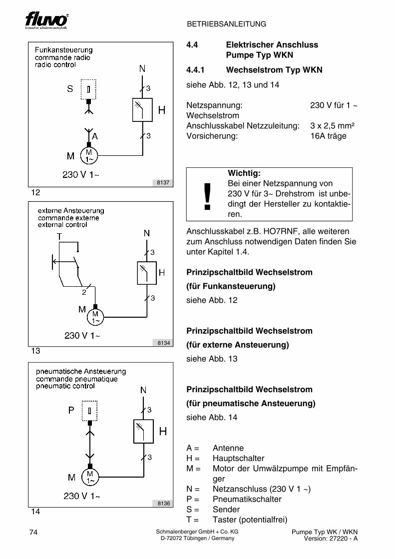
BETRIEBSANLEITUNG
74 Pumpe Typ WK / WKNVersion: 27220 - A
Schmalenberger GmbH + Co. KG D-72072 Tübingen / Germany
4.4 Elektrischer Anschluss Pumpe Typ WKN
4.4.1 Wechselstrom Typ WKN
siehe Abb. 12, 13 und 14
Netzspannung: 230 V für 1 ~WechselstromAnschlusskabel Netzzuleitung: 3 x 2,5 mm²Vorsicherung: 16A träge
Anschlusskabel z.B. HO7RNF, alle weiterenzum Anschluss notwendigen Daten finden Sieunter Kapitel 1.4.
Prinzipschaltbild Wechselstrom
(für Funkansteuerung)
siehe Abb. 12
Prinzipschaltbild Wechselstrom
(für externe Ansteuerung)
siehe Abb. 13
Prinzipschaltbild Wechselstrom
(für pneumatische Ansteuerung)
siehe Abb. 14
A = AntenneH = HauptschalterM = Motor der Umwälzpumpe mit Empfän-
gerN = Netzanschluss (230 V 1 ~)P = PneumatikschalterS = SenderT = Taster (potentialfrei)
!Wichtig:Bei einer Netzspannung von 230 V für 3~ Drehstrom ist unbe-dingt der Hersteller zu kontaktie-ren.
12
13
14
8137
8134
8136
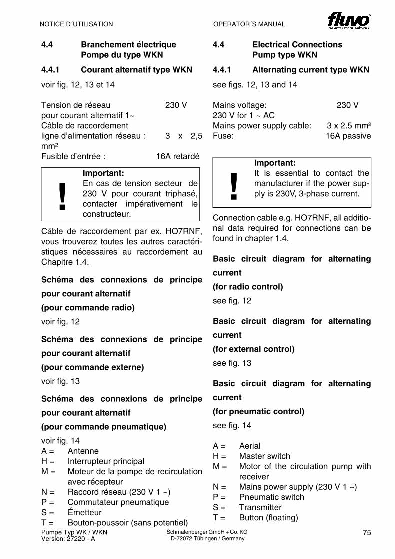
OPERATOR´S MANUALNOTICE D´UTILISATION
75Pumpe Typ WK / WKNVersion: 27220 - A
Schmalenberger GmbH + Co. KG D-72072 Tübingen / Germany
4.4 Branchement électrique Pompe du type WKN
4.4.1 Courant alternatif type WKN
voir fig. 12, 13 et 14
Tension de réseau 230 Vpour courant alternatif 1~Câble de raccordementligne d’alimentation réseau : 3 x 2,5mm²Fusible d’entrée : 16A retardé
Câble de raccordement par ex. HO7RNF,vous trouverez toutes les autres caractéri-stiques nécessaires au raccordement auChapitre 1.4.
Schéma des connexions de principe
pour courant alternatif
(pour commande radio)
voir fig. 12
Schéma des connexions de principe
pour courant alternatif
(pour commande externe)
voir fig. 13
Schéma des connexions de principe
pour courant alternatif
(pour commande pneumatique)
voir fig. 14A = AntenneH = Interrupteur principalM = Moteur de la pompe de recirculation
avec récepteurN = Raccord réseau (230 V 1 ~)P = Commutateur pneumatiqueS = ÉmetteurT = Bouton-poussoir (sans potentiel)
!Important:En cas de tension secteur de230 V pour courant triphasé,contacter impérativement leconstructeur.
4.4 Electrical ConnectionsPump type WKN
4.4.1 Alternating current type WKN
see figs. 12, 13 and 14
Mains voltage: 230 V230 V for 1 ~ ACMains power supply cable: 3 x 2.5 mm²Fuse: 16A passive
Connection cable e.g. HO7RNF, all additio-nal data required for connections can befound in chapter 1.4.
Basic circuit diagram for alternating
current
(for radio control)
see fig. 12
Basic circuit diagram for alternating
current
(for external control)
see fig. 13
Basic circuit diagram for alternating
current
(for pneumatic control)
see fig. 14
A = AerialH = Master switchM = Motor of the circulation pump with
receiverN = Mains power supply (230 V 1 ~)P = Pneumatic switchS = TransmitterT = Button (floating)
!Important:It is essential to contact themanufacturer if the power sup-ply is 230V, 3-phase current.

BETRIEBSANLEITUNG
76 Pumpe Typ WK / WKNVersion: 27220 - A
Schmalenberger GmbH + Co. KG D-72072 Tübingen / Germany
15
4.4.1.1 Anschlusskabel der Netz-zuleitung an Platine anschließen(Typ WKN, Wechselstrom)
siehe Abb. 15
Anschlusskabel Netzzuleitung 3 x 2,5 mm² inKlemmenkasten einziehen. Den 3-poligenSteckerabziehen, Aussenleiter (L1) und Null-leiter (L2) anklemmen; danach Stecker wiederauf die Platine stecken. Schutzleiter (101) an-klemmen.
L1 AussenleiterL2 NullleiterL3 nicht belegt101 PE grün/gelb (Schutzleiter)102 PE grün/gelb (Schutzleiter Klemmenka-
stendeckel)
Nach dem Einschalten des Hauptschalters 10Sekunden warten, bis die Initialisierung derSteuerung (LED „Batterie“ blinkt) abgeschlos-sen ist. Bei falscher Drehrichtung des Motorsleuchtet die LED „Drehfeld“ – siehe Kapitel 8„Fehlerhilfe“.
Achtung:Die Klemmenbelegung des 9-po-ligen Steckers darf nicht verän-dert werden!
8199

OPERATOR´S MANUALNOTICE D´UTILISATION
77Pumpe Typ WK / WKNVersion: 27220 - A
Schmalenberger GmbH + Co. KG D-72072 Tübingen / Germany
4.4.1.1 Branchement du câble de rac-cordement de la ligne d’ali-mentation réseau sur laplatine (Courant alternatiftype WKN)
voir fig. 15
Tirer le câble de raccordement de la ligned’alimentation réseau 3 x 2,5 mm² in dansla boîte à bornes. Débrancher le connec-teur mâle à 3 pôles, connecter le conduc-teur extérieur (L1) et le conducteur deprotection (L2); ensuite rebrancher le con-necteur mâle sur la platine. Connecter leconducteur de protection (101).
L1 Conducteur extérieur L2 Conducteur de protectionL3 non occupé101 PE vert/jaune (conducteur de pro-
tection)102 PE vert/jaune (conducteur de pro-
tection couvercle de boîte à bornes)
Après l’enclenchement de l’interrupteurprincipal, attendre 10 secondes jusqu’à ceque l’initialisation de la commande (La LED„batterie“ clignote) soit achevée. Tout fauxsens de rotation du moteur est signalé parl’allumage de la LED „Sens de rotation“ –voir Chapitre 8 „Aide aux défauts“.
Attention:Toute modification de la miseen état d’occupation des bor-nes du connecteur à 9 pôlesest interdite !
4.4.1.1 Connecting the mains powersupply cable to the printedcircuit board (Alternating cur-rent type WKN)
see fig. 15
Pull mains power supply cable 3 x 2.5 mm²into the terminal box. Remove the 3-poleplug, attach external conductor and protec-tive conductor (L2); then insert plug backonto the printed circuit board. Attach pro-tective conductor (101).
L1 External conductorL2 Protective conductorL3 not used101 PE green/yellow (protective con-
ductor)102 PE green/yellow (protective con-
ductor terminal box cover)
After switching on the master switch waitfor 10 seconds until the controller initialisa-tion (LED “battery” flashes) is complete. Ifthe direction of rotation of the motor iswrong LED „Phase sequence“ lights up,see chapter 8 „Fault assistance“.
Attention:The terminal assignments forthe 9-pole connector must notbe changed!

BETRIEBSANLEITUNG
78 Pumpe Typ WK / WKNVersion: 27220 - A
Schmalenberger GmbH + Co. KG D-72072 Tübingen / Germany
4.4.2 Drehstrom Typ WKN
Netzspannung: 230/400 Vfür 3 ~ DrehstromAnschlusskabel Netzzuleitung: 4 x 2,5 mm²Vorsicherung: 16A träge
Anschlusskabel z.B. HO7RNF, alle weiterenzum Anschluss notwendigen Daten finden Sieunter Kapitel 1.4.
Prinzipschaltbild Drehstrom
(für Funkansteuerung)
siehe Abb. 16
Prinzipschaltbild Drehstrom
(für externe Ansteuerung)
siehe Abb. 17
Prinzipschaltbild Drehstrom
(für pneumatische Ansteuerung)
siehe Abb. 18
A = AntenneH = HauptschalterM = Motor der Umwälzpumpe mit Empfän-
gerN = Netzanschluss (400 V 3 ~)P = PneumatikschalterS = SenderT = Taster (potentialfrei)
!Wichtig:Bei einer Netzspannung von 230 V für 3~ Drehstrom ist unbe-dingt der Hersteller zu kontaktie-ren.
16
18
17
8123
8124
8125

OPERATOR´S MANUALNOTICE D´UTILISATION
79Pumpe Typ WK / WKNVersion: 27220 - A
Schmalenberger GmbH + Co. KG D-72072 Tübingen / Germany
4.4.2 Courant triphasé type WKN
Tension de réseau 230/400 V pour courant triphasé
Câble de raccordementligne d’alimentation réseau : 4 x 2,5 mm²Fusible d’entrée : 16A retardé
Câble de raccordement par ex. HO7RNF,vous trouverez toutes les autres caractéri-stiques nécessaires au raccordement auChapitre 1.4.
Schéma des connexions de principe
pour courant triphasé
(pour commande radio)
voir fig. 16
Schéma des connexions de principe
pour courant triphasé
(pour commande externe)
voir fig. 17
Schéma des connexions de principe
pour courant triphasé
(pour commande pneumatique)
voir fig. 18
A = AntenneH = Interrupteur principalM = Moteur de la pompe de recirculation
avec récepteurN = Raccord réseau (400 V 3 ~)P = Commutateur pneumatiqueS = ÉmetteurT = Bouton-poussoir (sans potentiel)
!Important:En cas de tension secteur de230 V pour courant triphasé,contacter impérativement leconstructeur.
4.4.2 Three-phase current typeWKN
Mains voltage: 230/400 V for 3 ~ ACMains power supply cable: 4 x 2.5 mm²Fuse: 16A passive
Connection cable e.g. HO7RNF, all additio-nal data required for connections can befound in chapter 1.4.
Basic circuit diagram for 3-phase
current
(for radio control)
see fig. 16
Basic circuit diagram for 3-phase
current
(for external control)
see fig. 17
Basic circuit diagram for 3-phase
current
(for pneumatic control)
see fig. 18
A = AerialH = Master switchM = Motor of the circulation pump with
receiverN = Mains power supply (400 V 3 ~)P = Pneumatic switchS = TransmitterT = Button (floating)
!Important:It is essential to contact themanufacturer if the power sup-ply is 230V, 3-phase current.

BETRIEBSANLEITUNG
80 Pumpe Typ WK / WKNVersion: 27220 - A
Schmalenberger GmbH + Co. KG D-72072 Tübingen / Germany
19
4.4.2.1 Anschlusskabel der Netz-zuleitung an Platine anschließen(Typ WKN, Drehstrom)
siehe Abb. 19
Anschlusskabel Netzzuleitung 4 x 2,5 mm² inKlemmenkasten einziehen. Den 3-poligenSteckerabziehen, Aussenleiter anklemmenund Stecker wieder auf die Platine stecken.Schutzleiter (101) anklemmen.
L1 AussenleiterL2 AussenleiterL3 Aussenleiter101 PE grün/gelb (Schutzleiter)102 PE grün/gelb (Schutzleiter Klemmenka-
stendeckel)
Nach dem Einschalten des Hauptschalters 10Sekunden warten, bis die Initialisierung derSteuerung (LED „Batterie“ blinkt) abgeschlos-sen ist. Bei falscher Drehrichtung des Motorsleuchtet die LED „Drehfeld – siehe Kapitel 8.2„Fehlerhilfe“.
Achtung:Die Klemmenbelegung des 9-po-ligen Steckers darf nicht verän-dert werden!
8120

OPERATOR´S MANUALNOTICE D´UTILISATION
81Pumpe Typ WK / WKNVersion: 27220 - A
Schmalenberger GmbH + Co. KG D-72072 Tübingen / Germany
4.4.2.1 Branchement du câble de rac-cordement de la ligne d’ali-mentation réseau sur laplatine (Courant triphasé typeWKN)
voir fig. 19
Tirer le câble de raccordement de la ligned’alimentation réseau 4 x 2,5 mm² in dansla boîte à bornes. Débrancher le connec-teur mâle à 3 pôles, connecter le conduc-teur extérieur et rebrancher le connecteurmâle sur la platine. Connecter le conduc-teur de protection (101).
L1 Conducteur extérieur L2 Conducteur extérieur L3 Conducteur extérieur 101 PE vert/jaune (conducteur de pro-
tection)102 PE vert/jaune (conducteur de pro-
tection couvercle de boîte à bornes)
Après l’enclenchement de l’interrupteurprincipal, attendre 10 secondes jusqu’à ceque l’initialisation de la commande (La LED„batterie“ clignote) soit achevée. Tout fauxsens de rotation du moteur est signalé parl’allumage de la LED „Sens de rotation“– voir Chapitre 8.2 „Aide aux défauts“.
Attention:Toute modification de la miseen état d’occupation des bor-nes du connecteur à 9 pôlesest interdite !
4.4.2.1 Connecting the mains powersupply cable to the printedcircuit board (Three-phasecurrent type WKN)
see fig. 19
Pull mains power supply cable 4 x 2.5 mm²into the terminal box. Remove the 3-poleplug, attach external conductor and insertplug back onto the printed circuit board. At-tach protective conductor (101).
L1 External conductorL2 External conductorL3 External conductor101 PE green/yellow (protective con-
ductor)102 PE green/yellow (protective con-
ductor terminal box cover)
After switching on the master switch waitfor 10 seconds until the controller initialisa-tion (LED “battery” flashes) is complete. Ifthe direction of rotation of the motor iswrong LED „Phase sequence“ lights up,see chapter 8.2 „Fault assistance“.
Attention:The terminal assignments forthe 9-pole connector must notbe changed!

BETRIEBSANLEITUNG
82 Pumpe Typ WK / WKNVersion: 27220 - A
Schmalenberger GmbH + Co. KG D-72072 Tübingen / Germany
4.4.3 Einstellung der Betriebsdauer
siehe Abb. 20
Die Einstellung der Betriebsdauer darf nur vomFachmann vorgenommen werden.
Die Betriebsdauer kann in 4 min-Schritten von4 bis 60 min am Timer (X) mit einem Schrau-bendreher eingestellt werden.Werksseitig ist die Betriebsdauer auf D (Dauer-betrieb) eingestellt.
X Timer
Achtung!
Vor dem Öffnen des Klemmkasten-deckels Hauptschalter ausschaltenund Sicherungenaus dem Siche-rungskasten nehmen!
Bezeichnung Timer (X) Dauer (min)
4 4
* 8
* 12
16 16
* 20
* 24
28 28
* 32
* 36
101 101
* 44
* 48
103 103
* 56
* 60
D Dauerbetrieb
208196
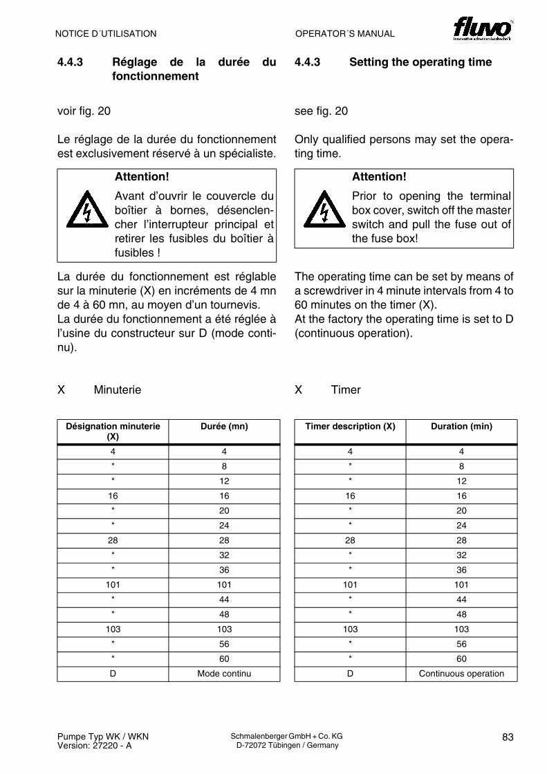
OPERATOR´S MANUALNOTICE D´UTILISATION
83Pumpe Typ WK / WKNVersion: 27220 - A
Schmalenberger GmbH + Co. KG D-72072 Tübingen / Germany
4.4.3 Réglage de la durée dufonctionnement
voir fig. 20
Le réglage de la durée du fonctionnementest exclusivement réservé à un spécialiste.
La durée du fonctionnement est réglablesur la minuterie (X) en incréments de 4 mnde 4 à 60 mn, au moyen d’un tournevis.La durée du fonctionnement a été réglée àl’usine du constructeur sur D (mode conti-nu).
X Minuterie
Attention!
Avant d’ouvrir le couvercle duboîtier à bornes, désenclen-cher l’interrupteur principal etretirer les fusibles du boîtier àfusibles !
Désignation minuterie (X)
Durée (mn)
4 4
* 8
* 12
16 16
* 20
* 24
28 28
* 32
* 36
101 101
* 44
* 48
103 103
* 56
* 60
D Mode continu
4.4.3 Setting the operating time
see fig. 20
Only qualified persons may set the opera-ting time.
The operating time can be set by means ofa screwdriver in 4 minute intervals from 4 to60 minutes on the timer (X). At the factory the operating time is set to D(continuous operation).
X Timer
Attention!
Prior to opening the terminalbox cover, switch off the masterswitch and pull the fuse out ofthe fuse box!
Timer description (X) Duration (min)
4 4
* 8
* 12
16 16
* 20
* 24
28 28
* 32
* 36
101 101
* 44
* 48
103 103
* 56
* 60
D Continuous operation

BETRIEBSANLEITUNG
84 Pumpe Typ WK / WKNVersion: 27220 - A
Schmalenberger GmbH + Co. KG D-72072 Tübingen / Germany
4.4.4 Einstellung der Empfänger-adresse
siehe Abb. 21
Die Einstellung der Empfängeradresse darf nurvon einem Fachmann vorgenommen werden.
Es können insgesamt 8 verschiedene Empfän-geradressen mit einem Schraubendreher amDrehschalter (Y) eingestellt werden. Werkssei-tig ist die Empfängeradresse bzw. Kodierung 0eingestellt.
Bei Verwendung einer anderen Empfänger-adresse (1 bis 7) muss der Sender dieentsprechende Kodierung haben. Eine nach-trägliche Änderung der Kodierung des Sendersist nicht möglich. Mit der Empfängeradresse 0kann mit jedem Sender eingeschaltet werden.
Y Drehschalter
Achtung!
Vor dem Öffnen des Klemmkasten-deckels Hauptschalter ausschaltenund Sicherungen aus dem Siche-rungskasten nehmen!
Bezeichnung Drehschalter (Y)
Kodierung des Senders
0 0
1 1
2 2
3 3
4 4
5 5
6 6
7 7
218197

OPERATOR´S MANUALNOTICE D´UTILISATION
85Pumpe Typ WK / WKNVersion: 27220 - A
Schmalenberger GmbH + Co. KG D-72072 Tübingen / Germany
4.4.4 Réglage de l’adresse durécepteur
voir fig. 21
Le réglage de l’adresse du récepteur estexclusivement réservé à un spécialiste.
Au total, il est possible de régler 8 adressesde récepteur différentes en appliquant untournevis sur le commutateur rotatif . Leréglage usine a été effectué à l’adresse ré-cepteur voire au codage 0.
Lors de l’utilisation d’une autre adresse derécepteur (de 1 à 7), veiller à ce que l’émet-teur soit doté du codage approprié. Toutemodification ultérieure du codage del’émetteur est impossible. L’adresse derécepteur 0 peut être activée par chaqueémetteur.
Y Commutateur rotatif
Attention!
Avant d’ouvrir le couvercle duboîtier à bornes, désenclencherl’interrupteur principal et retirerles fusibles du boîtier à fusibles!
Désignation commuta-teur rotatif (Y)
Codage de l’émetteur
0 0
1 1
2 2
3 3
4 4
5 5
6 6
7 7
4.4.4 Setting the receiver address
see fig. 21
Only qualified persons may set the receiveraddress.
A total of 8 different receiver addresses canbe set by means of a screwdriver on the ro-tary switch (Y) . At the factory the receiveraddress or code is set to 0.
If a different receiver address (1 to 7) is tobe used, then the transmitter must alsohave the corresponding code. A subse-quent change in the transmitter code is notpossible. With the receiver address 0 anytransmitter may be used to switch on.
Y Rotary switch
Attention!
Prior to opening the terminalbox cover, switch off the masterswitch and pull the fuse out ofthe fuse box!
Rotary switch descrip-tion (Y)
Transmitter code
0 0
1 1
2 2
3 3
4 4
5 5
6 6
7 7
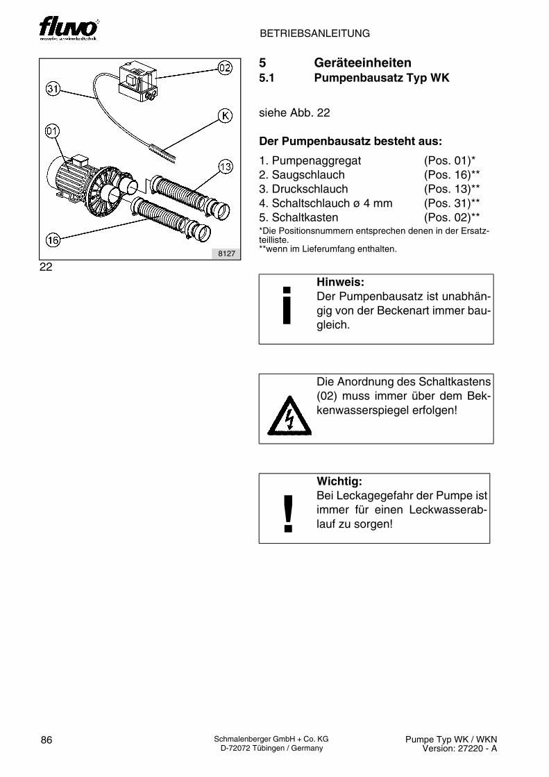
BETRIEBSANLEITUNG
86 Pumpe Typ WK / WKNVersion: 27220 - A
Schmalenberger GmbH + Co. KG D-72072 Tübingen / Germany
5 Geräteeinheiten5.1 Pumpenbausatz Typ WK
siehe Abb. 22
Der Pumpenbausatz besteht aus:
1. Pumpenaggregat (Pos. 01)*2. Saugschlauch (Pos. 16)**3. Druckschlauch (Pos. 13)**4. Schaltschlauch ø 4 mm (Pos. 31)**5. Schaltkasten (Pos. 02)***Die Positionsnummern entsprechen denen in der Ersatz-teilliste.**wenn im Lieferumfang enthalten.
iHinweis:Der Pumpenbausatz ist unabhän-gig von der Beckenart immer bau-gleich.
Die Anordnung des Schaltkastens(02) muss immer über dem Bek-kenwasserspiegel erfolgen!
!Wichtig:Bei Leckagegefahr der Pumpe istimmer für einen Leckwasserab-lauf zu sorgen!
228127
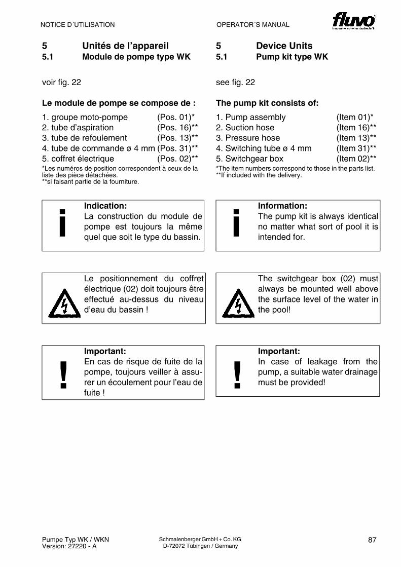
OPERATOR´S MANUALNOTICE D´UTILISATION
87Pumpe Typ WK / WKNVersion: 27220 - A
Schmalenberger GmbH + Co. KG D-72072 Tübingen / Germany
5 Unités de l’appareil5.1 Module de pompe type WK
voir fig. 22
Le module de pompe se compose de :
1. groupe moto-pompe (Pos. 01)*2. tube d’aspiration (Pos. 16)**3. tube de refoulement (Pos. 13)**4. tube de commande ø 4 mm (Pos. 31)**5. coffret électrique (Pos. 02)***Les numéros de position correspondent à ceux de la liste des pièce détachées.**si faisant partie de la fourniture.
iIndication:La construction du module depompe est toujours la mêmequel que soit le type du bassin.
Le positionnement du coffretélectrique (02) doit toujours êtreeffectué au-dessus du niveaud’eau du bassin !
!Important:En cas de risque de fuite de lapompe, toujours veiller à assu-rer un écoulement pour l’eau defuite !
5 Device Units5.1 Pump kit type WK
see fig. 22
The pump kit consists of:
1. Pump assembly (Item 01)*2. Suction hose (Item 16)**3. Pressure hose (Item 13)**4. Switching tube ø 4 mm (Item 31)**5. Switchgear box (Item 02)***The item numbers correspond to those in the parts list. **If included with the delivery.
iInformation:The pump kit is always identicalno matter what sort of pool it isintended for.
The switchgear box (02) mustalways be mounted well abovethe surface level of the water inthe pool!
!Important:In case of leakage from thepump, a suitable water drainagemust be provided!

BETRIEBSANLEITUNG
88 Pumpe Typ WK / WKNVersion: 27220 - A
Schmalenberger GmbH + Co. KG D-72072 Tübingen / Germany
5.2 Pumpenbausatz Typ WKN
siehe Abb. 23
Der Pumpenbausatz besteht aus:
1. Pumpenaggregat (Pos. 01)*2. Saugschlauch (Pos. 16)**3. Druckschlauch (Pos. 13)**4. Sender (Pos. 19)**5. Antenne (Pos. 33)***Die Positionsnummern entsprechen denen in der Ersatz-teilliste.**wenn im Lieferumfang enthalten.
a= max. 1 m
5.2.1 Sendeeinheit Typ mono
iHinweis:Der Pumpenbausatz ist unabhän-gig von der Beckenart immer bau-gleich.
Die Anordnung des Senders (19)und der Antenne (33) muss wie inKap. 6.4 beschrieben erfolgen.
!Wichtig:Der lichte Abstand zwischen Sen-der (19) und Antenne (33) darfa=1m nicht überschreiten.
238128

OPERATOR´S MANUALNOTICE D´UTILISATION
89Pumpe Typ WK / WKNVersion: 27220 - A
Schmalenberger GmbH + Co. KG D-72072 Tübingen / Germany
5.2 Module de pompe type WKN
voir fig. 23
Le module de pompe se compose de:
1. groupe moto-pompe (Pos. 01)*2. tube d’aspiration (Pos. 16)**3. tube de refoulement (Pos. 13)**4. émetteur (Pos. 19)**5. antenne (Pos. 33)***Les numéros de position correspondent à ceux de la liste des pièce détachées.**si faisant partie de la fourniture.
a= max. 1 m
5.2.1 Unité émettrice type mono
iIndication:La construction du module depompe est toujours la mêmequel que soit le type du bassin.
Le positionnement de l’émetteur(19) et de l’antenne (33) doitêtre effectué selon la descripti-on fournie au chap. 6.4.
!Important:L’écartement entre l’émetteur(19) et l’antenne (33) ne doit pasdépasser a=1m.
5.2 Pump kit type WKN
see fig. 23
The pump kit consists of:
1. Pump assembly (Item 01)*2. Suction hose (Item 16)**3. Pressure hose (Item 13)**4. Transmitter (Item 19)**5. Aerial (Item 33)***The item numbers correspond to those in the parts list. **If included with the delivery.
a= max. 1 m
5.2.1 Transmitter type mono
iInformation:The pump kit is always identicalno matter what sort of pool it isintended for.
The locations of the transmitter(19) and the aerial (33) must beas described in chapter 6.4.
!Important:The direct distance between thetransmitter (19) and the aerial(33) must not exceed a = 1m.

90 Pumpe Typ WK / WKNVersion: 27220 - A
Schmalenberger GmbH + Co. KG D-72072 Tübingen / Germany
BETRIEBSANLEITUNG / NOTICE D´UTILISATION / OPERATOR´S MANUAL
24
Einbau der Sendeeinheit im Becken /
Montage de l’unité émettrice dans le bassin /
Installing the transmitter in the pool
siehe Abb. 24 / voir fig. 24 / see fig. 24
Maße / Measures / Dimensions
a = max. 1 m
Pos. Benennung Désignation Description
99 Sendeeinheit Typ monokomplett
Unité émettrice Type mono complet
Transmitter type mono complete
33 Antenne Antenne Aerial
8129

91Pumpe Typ WK / WKNVersion: 27220 - A
Schmalenberger GmbH + Co. KG D-72072 Tübingen / Germany
BETRIEBSANLEITUNG / NOTICE D´UTILISATION / OPERATOR´S MANUAL
25
Einbau der Sendeeinheit außerhalb des Beckens /
Montage de l’unité émettrice en dehors du bassin /
Installing the transmitter outside the pool
siehe Abb. 25 / voir fig. 25 / see fig. 25
Maße / Measures / Dimensions
a = max. 1 m
Pos. Benennung Désignation Description
99 Sendeeinheit Typ monokomplett
Unité émettrice Type mono complet
Transmitter type mono complete
33 Antenne Antenne Aerial
8130

BETRIEBSANLEITUNG
92 Pumpe Typ WK / WKNVersion: 27220 - A
Schmalenberger GmbH + Co. KG D-72072 Tübingen / Germany
6 Montage6.1 Montage allgemein
siehe Abb. 26
Montieren Sie den Grundrahmen am vorgese-henen Platz. Befestigen Sie den Grundrahmenmit 4 Schrauben (44).
Der Grundrahmen sollte gegen Boden undWand isoliert befestigt werden (I), um Fremd-spannungsübertragung zu vermeiden.
b = 160 mm
I Isolation
44 Schrauben
6.2 Montage des Schaltkastens (nur bei Typ WK)
siehe Abb. 27
Den Schaltkasten (02) möglichst nahe an denEinbausatz montieren.Den Schaltschlauch (31) auf den Nippel imSchutzschlauch (K) stecken.
K Schutzschlauch
02 Schaltkasten31 Schaltschlauch
iHinweis:Den Schaltschlauch nicht knickenund so kurz wie möglich halten.
Maximale Länge 8m.
26
27
8131
8132

OPERATOR´S MANUALNOTICE D´UTILISATION
93Pumpe Typ WK / WKNVersion: 27220 - A
Schmalenberger GmbH + Co. KG D-72072 Tübingen / Germany
6 Montage6.1 Montage en général
voir fig. 26
Monter le cadre de base à l’endroit prévu.Fixer le cadre de base au moyen de 4 vis(44).
Nous préconisons de fixer le cadre de baseen l’isolant du sol et de la paroi (I) pouréviter toute transmission de tensiond’origine étrangère.
b = 160 mm
I Isolation
44 Vis
6.2 Montage du coffret électrique(uniquement pour le type WK)
voir fig. 27
Monter le coffret électrique (02) le plus prèspossible de la pièce à sceller.Brancher le tube de commande (31) sur leraccord fileté dans la gaine protectrice (K).
K Gaine protectrice
02 Coffret électrique31 Tube de commande
iIndication:Ne pas plier le tube decommande et le mainteniraussi court que possible.Longueur maximale 8m.
6 Installation6.1 Installation - general
see fig. 26
Place the base frame in the desiredposition. Fasten the base frame with 4screws (44).
The base frame should be installed in sucha way that it is insulated from the floor andthe wall (I) to avoid the possibility ofexternal voltage transmissions.
b = 60 mm
I Insulation
44 Screws
6.2 Installing the switchgear box(only for type WK)
see fig. 27
Mount the switchgear box (02) as close aspossible to the installation kit. Fix the switching tube (31) onto the nipplein the protective hose (K).
K Protective hose
02 Switchgear box31 Switching tube
iInformation:Do not put a kink in the switchingtube and keep it as short aspossible. Maximum length 8m.

BETRIEBSANLEITUNG
94 Pumpe Typ WK / WKNVersion: 27220 - A
Schmalenberger GmbH + Co. KG D-72072 Tübingen / Germany
28
6.3 Montage der Antenne (nur bei Typ WKN)
siehe Abb. 28
Die Antenne (33) in der Nähe des Senders (19)mit dem Befestigungssatz (21) parallel zurBeckenwand montieren.
Den Abstand zwischen Sender (19) und Anten-ne (33) so kurz wie möglich einrichten.
a = max. 1m
01 Pumpenaggregat13 Druckschlauch16 Saugschlauch19 Sender21 Befestigungssatz33 Antenne
iHinweis:Der lichte Abstand zwischen Sen-der (19) und Antenne (33) darf 1mnicht überschreiten.
8133
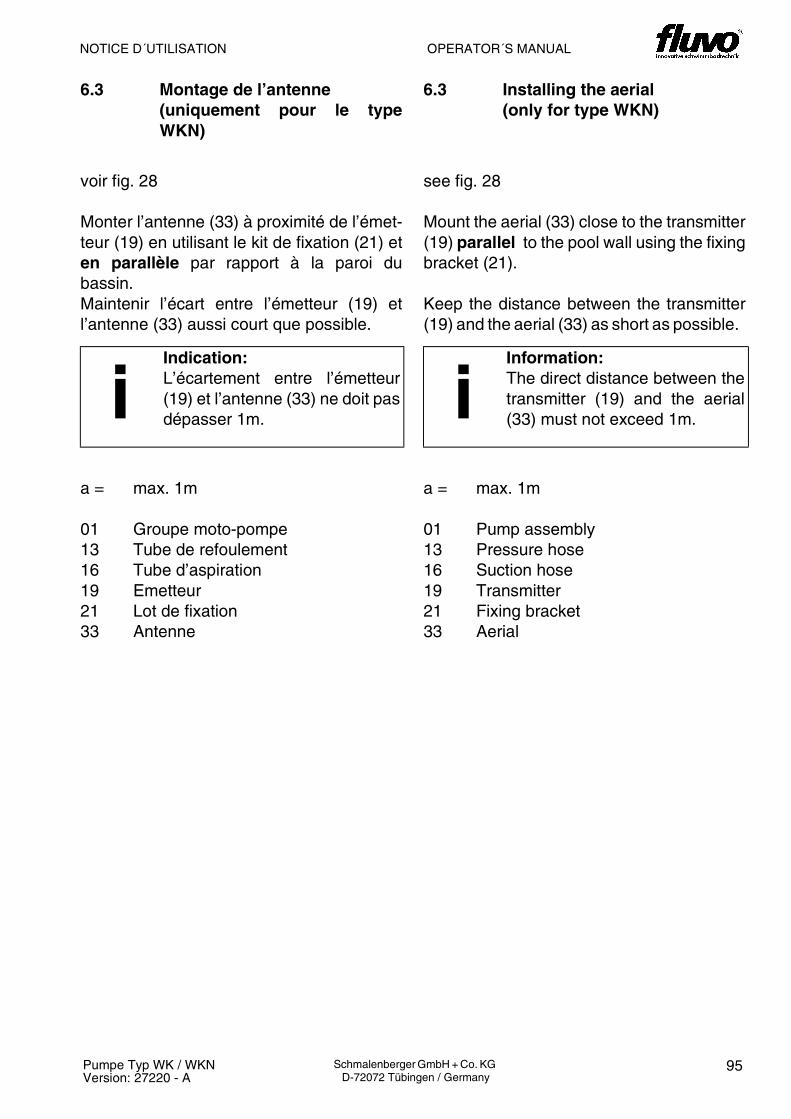
OPERATOR´S MANUALNOTICE D´UTILISATION
95Pumpe Typ WK / WKNVersion: 27220 - A
Schmalenberger GmbH + Co. KG D-72072 Tübingen / Germany
6.3 Montage de l’antenne (uniquement pour le typeWKN)
voir fig. 28
Monter l’antenne (33) à proximité de l’émet-teur (19) en utilisant le kit de fixation (21) eten parallèle par rapport à la paroi dubassin.Maintenir l’écart entre l’émetteur (19) etl’antenne (33) aussi court que possible.
a = max. 1m
01 Groupe moto-pompe13 Tube de refoulement16 Tube d’aspiration19 Emetteur21 Lot de fixation33 Antenne
iIndication:L’écartement entre l’émetteur(19) et l’antenne (33) ne doit pasdépasser 1m.
6.3 Installing the aerial(only for type WKN)
see fig. 28
Mount the aerial (33) close to the transmitter(19) parallel to the pool wall using the fixingbracket (21).
Keep the distance between the transmitter(19) and the aerial (33) as short as possible.
a = max. 1m
01 Pump assembly13 Pressure hose16 Suction hose19 Transmitter21 Fixing bracket33 Aerial
iInformation:The direct distance between thetransmitter (19) and the aerial(33) must not exceed 1m.

BETRIEBSANLEITUNG
96 Pumpe Typ WK / WKNVersion: 27220 - A
Schmalenberger GmbH + Co. KG D-72072 Tübingen / Germany
FLUVO
W
75.279
75.1
75.1
34
29
6.4 Montage des Senders
siehe Abb. 29
Ziehen Sie an der Halteplatte (75.1) die blaueSchutzfolie vom Klebestreifen (34) ab. RichtenSie die Halteplatte (75.1) so aus, wie in Abb. 28gezeigt!!
Drücken Sie dann die Halteplatte (75.1) samtdem Klebestreifen (34) 5 Sekunden fest an dieBeckenwand (A) an. Führen Sie das Funkge-häuse (79) mit dem Haltedeckel (75.2) vonoben in die Halteplatte (75.1) ein, bis der Hal-tedeckel (75.2) in der Halteplatte (75.1) einra-stet.
W Beckenwand
34 Klebestreifen75.1 Halterung75.2 Halteplatte79 Funkgehäuse
!Wichtig:Die Einkerbungen für die Halteplat-te (75.1) müssen nach oben zei-gen!
!Wichtig:Zur Überwinterung ist das Funkge-häuse (79) aus der Halteplatte(75.1) zu entnehmen und beiRaumtemperatur zu lagern.
8207

OPERATOR´S MANUALNOTICE D´UTILISATION
97Pumpe Typ WK / WKNVersion: 27220 - A
Schmalenberger GmbH + Co. KG D-72072 Tübingen / Germany
6.4 Montage de l’émetteur
voir fig. 29
Décoller le film protecteur bleu de la bandeadhésive (34) sur la plaque de retenue(75.1). Aligner la plaque de retenue (75.1)comme sur la Fig. 28 !!
Presser ensuite fortement la plaque de re-tenue (75.1), bande adhésive (34) compri-se, pendant 5 secondes contre la paroi dubassin (A). Par le haut, introduire le boîtierradio (79), couvercle de retenue (75.2)compris, dans la plaque de retenue (75.1)jusqu’à ce que le couvercle de retenue(75.2) s’emboîte dans la plaque de retenue(75.1).
W Paroi du bassin
34 Bande adhésive75.1 Fixation75.2 Plaque de retenue79 Boîtier radio
!Important:Les encoches pour la plaque deretenue (75.1) doivent êtretournées vers le haut !
!Important:Pour la mise en hivernage,démonter le boîtier radio (79) dela plaque de retenue (75.1) etl’entreposer à températureambiante.
6.4 Installing the transmitter
see fig. 29
Pull the blue protective foil from the stickytape (34) on the mounting plate (75.1).Position the mounting plate (75.1) preciselyas shown in fig. 28!!
Then press the mounting plate (75.1)together with the sticky tape (34) firmly ontothe wall of the pool (A) for 5 seconds. Insertthe wireless housing (79) with its holder(75.2) from above into the mounting plate(75.1) until the holder (75.2) engages withthe mounting plate (75.1).
W Pool wall
34 Sticky tape75.1 Holding device75.2 Mounting plate79 Wireless housing
!Important:The notches for the mountingplate (75.1) must pointupwards!
!Important:Over winter the wireless housing(79) must be removed from themounting plate (75.1) and storedat room temperature.

BETRIEBSANLEITUNG
98 Pumpe Typ WK / WKNVersion: 27220 - A
Schmalenberger GmbH + Co. KG D-72072 Tübingen / Germany
30
6.5 Anschluss Pumpenansteuerung(nur bei Typ WKN)
siehe Abb. 30
Pumpen vom Typ WKN können über Funkan-steuerung (Sender), externe Ansteuerung (po-tentialfreier Taster) oder pneumatische An-steuerung (z.B. Druckwellenschalter) ein- bzw.ausgeschaltet werden.
6.5.1 Funkansteuerung
Die Montage von Antenne (33) und Sender(19) wird in Kapitel 6.3 beschrieben.
6.5.2 Externe Ansteuerung
Schrauben Sie das abgeschirmte Kabel für dieexterne Ansteuerung am Anschluss für die ex-terne Ansteuerung (55) fest.Die Weiterführung des Kabels darf ebenfallsnur in abgeschirmter Form erfolgen!
6.5.3 Pneumatische Ansteuerung
Stecken Sie den Schlauch für die pneumati-sche Ansteuerung auf den Nippel (56) auf.
D Deckel
54 Anschluss für Funkansteuerung (Winkelstecker für Antenne)
55 Anschluss für externe Ansteuerung (RS 485-Schnittstelle)
56 Anschluss für pneumatische Ansteue-rung (Schlauchnippel)
Achtung:Es darf nur das von fluvo geliefer-te Kabel verwendet werden!
!Wichtig:Der Schlauch muss sicher und di-rekt aufgesteck sein.Das Quetschen des Nippels samtSchlauch mittels eines Werk-zeugs ist nicht zulässig.
8203

OPERATOR´S MANUALNOTICE D´UTILISATION
99Pumpe Typ WK / WKNVersion: 27220 - A
Schmalenberger GmbH + Co. KG D-72072 Tübingen / Germany
6.5 Raccordement commande depompe (que pour le type WKN)
voir figure 30
La mise en voire hors service des pompesdu type WKN peut être effectuée par le biaisd’une commande radio (émetteur), d’unecommande externe (bouton-poussoir sanspotentiel) ou de commande pneumatique(par ex. interrupteur à onde de pression).
6.5.1 Commande radio
Le montage de l’antenne (33) et del’émetteur (19) est décrit au chapitre 6.3.
6.5.2 Commande externe
Visser le câble blindé de la commandeexterne à fond sur la prise de commandeexterne (55).Ne continuer la pose du câble que sous uneforme également blindée !
6.5.3 Commande pneumatique
Emmancher le tuyau destiné à la commandepneumatique sur le mamelon (56).
D Couvercle54 Raccordement de la commande radio
(connecteur coudé pour antenne)55 Raccordement de commande externe
(interface RS 485)56 Raccordement pour commande pneu-
matique (mamelon de tuyau)
Attention!Il n’est permis d’utiliser que le câ-ble faisant partie de la fourniturefluvo !
!Important:Veiller à ce que le tuyau soit em-manché fiablement et direc-te-ment.Il est interdit d’écraser le mamelon,tuyau compris, au moyen d’un ou-til.
6.5 Pump control connection (on-ly for type WKN)
see fig. 30
Pump types WKN can be switched on or offusing radio control (transmitter), externalcontrol (floating button) or pneumatic control(e.g. pressure switch).
6.5.1 Radio control
The fitting of aerial (33) and transmitter (19)is described in chapter 6.3.
6.5.2 External control
Screw the screened cable for externalcontrol tightly to the connection for externalcontrol (55).The cable must screened throughout itsentire length!
6.5.3 Pneumatic control
Place the hose for pneumatic control ontothe nipple (56).
D Cover54 Connection for radio control
(angle contact plug for aerial)55 Connection for external control
(RS 485 interface)56 Connection for pneumatic control
(hose nipple)
Warning!Make sure that only the cabledelivered by fluvo is used!
!Important:The hose must be pushed onsecurely and directly.It is not permitted to crush thenipple and hose with some kindof tool.
BETRIEBSANLEITUNG
100 Pumpe Typ WK / WKNVersion: 27220 - A
Schmalenberger GmbH + Co. KG D-72072 Tübingen / Germany
7 Betrieb der Kreiselpumpe
7.1 Erstinbetriebnahme
1. die Kreiselpumpe vorschriftengerecht elektrisch mit allen Schutzeinrichtungen ange-schlossen ist,
2. die Kreiselpumpe mit Fördermedium gefüllt ist und Zulauf hat.
3. saugseitig alle Absperrorgane geöffnet sind und die Pumpe sowie die Saugleitung ent-lüftet sind.
4. Beachten Sie: Trockenlauf führt zu erhöhtem Verschleiß und ist unbedingt zu vermei-den!
5. die rotierenden Teile der Kreiselpumpe mit einem Berührungsschutz versehen sind.(Gemäß UVV darf die Pumpe nur mit einem Berührungsschutz betrieben werden.)
6. die Welle der Kreiselpumpe auf Leichtlauf geprüft wurde. Beachten Sie die Hinweiseunter 9.1.
7. die Drehrichtung geprüft wurde.
7.1.1 Kreiselpumpe starten
Die Kreiselpumpe nur bei halb offenem druckseitigem und vollständig geöffnetem saugsei-tigem Absperrorgan einschalten! Erst nach Erreichen der vollen Drehzahl dieses langsamöffnen und auf den Betriebspunkt einregeln.
! Wichtig:Stellen Sie sicher, dass vor der Erstinbetriebnahme der Kreiselpumpe folgendeVoraussetzungen erfüllt sind:

NOTICE D´UTILISATION
101Pumpe Typ WK / WKNVersion: 27220 - A
Schmalenberger GmbH + Co. KG D-72072 Tübingen / Germany
7 Exploitation de la pompe centrifuge
7.1 Première mise en service
1. branchement électrique correct avec tous les dispositifs de protection répondant auxcritères des prescriptions,
2. remplissage correct du fluide refoulé dans la pompe centrifuge qui doit être dotée d’unealimentation.
3. tous les organes d’arrêt sont ouverts côté aspiration et la pompe, ainsi que les con-duites d’aspiration sont purgées.
4. Note: Toute marche à sec implique une usure accrue et doit impérativement êtreévitée!
5. Les pièces en rotation de la pompe centrifuge doivent être dotées d’une protectionanticontact. (Conformément à la réglementation UVV (prévention des accidents dutravail), l’exploitation de la pompe n’est permise qu’avec une protection anticontact.)
6. Contrôler si la marche de l’arbre de la pompe centrifuge n’est pas grippée. Respecterles consignes fournies sous 9.1.
7. le sens de rotation a été vérifié.
7.1.1 Démarrage de la pompe centrifuge
Ne mettre la pompe centrifuge en service que lorsque l’organe d’arrêt installé sur le côtérefoulement est à moitié ouvert ! Ouvrir celui-ci lentement jusqu’au point defonctionnement uniquement après avoir atteint la vitesse de rotation totale.
! Important:Avant la première mise en service, s’assurer que la pompe centrifuge répondaux conditions prérequises suivantes:
OPERATOR’S MANUAL
102 Pumpe Typ WK / WKNVersion: 27220 - A
Schmalenberger GmbH + Co. KG D-72072 Tübingen / Germany
7 Operating the Centrifugal Pump
7.1 Initial Start-up
1. The centrifugal pump has been connected properly electrically and with all requisitesafety features.
2. The centrifugal pump has been filled with delivery medium and has supply.
3. On the suction side all shut-off devices are open and the pump as well as the suctionpipe are vented.
4. Please observe: Running dry creates increased wear and must be avoided at all costs!
5. The rotating parts of the centrifugal pump have been covered by a protective shield. (Inaccordance with UVV (Accident Prevention Regulations) the centrifugal pump mayonly be operated if a safety shield has been fitted).
6. It has been checked that the centrifugal pump shaft rotates easily. Please observe theinstructions under 9.1.
7. The direction of rotation has been checked.
7.1.1 Start the centrifugal pump
Make sure that the shut-off device on the pressure end is half open before starting thecentrifugal pump up! Once the maximum rotation speed has been reached, slowly open itup and adjust to full operational level.
! Important:Prior to initially starting up the centrifugal pump please make sure that thefollowing prerequisites have been met:

103Pumpe Typ WK / WKNVersion: 27220 - A
Schmalenberger GmbH + Co. KG D-72072 Tübingen / Germany
BETRIEBSANLEITUNG / NOTICE D´UTILISATION / OPERATOR´S MANUAL

BETRIEBSANLEITUNG
104 Pumpe Typ WK / WKNVersion: 27220 - A
Schmalenberger GmbH + Co. KG D-72072 Tübingen / Germany
7.2 Betreiben
7.2.1 Betriebsüberwachung
In den meisten Fällen wird die Kreiselpumpe von der zentralen Steuerung der Gesamtan-lage geregelt. Die Einhaltung der bei der Auslegung der Kreiselpumpe für den Einsatz-zweck bestimmten Daten, siehe Spezifikation, sind Voraussetzung für eine einwandfreieFunktion.
1. Temperatur der Förderflüssigkeit: Die Kreiselpumpe darf nur bei Wassertemperatu-ren von t = 0 bis +50°C betrieben werden.
2. Temperatur der Motorkühlluft: Die maximale Temperatur der Motorkühlluft beträgt40°C. Sollten höhere Temperaturen auftreten (z.B. in einem Pumpenschacht) ist füreine ausreichende Belüftung zu sorgen.
3. Schalthäufigkeit: Um starken Temperaturanstieg im Motor und übermäßige Be-lastung von Kreiselpumpe, Motor, und Lagern zu vermeiden, darf ein Einschaltvorgangpro Minute nicht überschritten werden.
4. Mindestmenge: Wenn die Art der Anlage die Möglichkeit eines Laufes gegen druck-seitig geschlossenes Absperrorgan einschließt, ist während dieser Zeit, um ein über-mäßiges Erwärmen der Pumpenhydraulik auszuschließen, ein Mindestförderstrom beit = 0 bis +50°C von 2 m³/h vorzusehen (z.B: Bypass).
5. Dichte der Förderflüsigkeit: Die Leistungsaufnahme der Pumpe ändert sich propor-tional zur Dichte der Förderflüssigkeit. Um Überlastung des Motors zu vermeiden,mussdie Dichte mit den Spezifikationsdaten übereinstimmen.
7.2.2 Sonstiges
Installierte Reservepumpen müssen 1 x wöchentlich kurzzeitig in Betrieb genommen wer-den, damit die Gewähr für stete Betriebsbereitschaft gegeben ist. Die Betriebsdauer solltejeweils ca. 15 Minuten betragen.
!Wichtig:Die nachfolgend genannten Punkte sind besonders beim manuellen Betriebder Kreiselpumpe zu beachten:

NOTICE D´UTILISATION
105Pumpe Typ WK / WKNVersion: 27220 - A
Schmalenberger GmbH + Co. KG D-72072 Tübingen / Germany
7.2 Exploitation
7.2.1 Surveillance du fonctionnement
Dans la plupart des cas la pompe centrifuge est régulée depuis la commande centrale del’installation globale. Le respect des caractéristiques déterminées lors de la conception dela pompe centrifuge pour sa finalité, voir la spécification, est une condition prérequise pourson fonctionnement impeccable.
1. Température du liquide refoulé : Ne faire fonctionner la pompe centrifuge qu’à destempératures d’eau de t = de 0 à +50°C.
2. Température de l’air de refroidissement du moteur : La température maximale del’air de refroidissement du moteur s’élève à 40°C. En cas d’apparition de températuresplus élevées (par ex. dans un canal de pompage), veiller à une ventilation suffisante.
3. Fréquence de commutation : Afin d’éviter une hausse de la température du moteuret une contrainte trop importante de la pompe centrifuge, du moteur et des paliers, selimiter à un processus de commutation par minute.
4. Quantité minimale : Lorsque le type de l’installation intègre la possibilité d’unemarche contre un organe d’arrêt fermé côté pression, prévoir pendant ce temps undébit de liquide refoulé minimal de 2 m³/h pour t = de 0 à +50°C afin d’exclure toutéchauffement excessif du groupe hydraulique de la pompe (par ex. : by-pass).
5. Densité du liquide refoulé : La puissance absorbée de la pompe varieproportionnellement par rapport à la densité du liquide refoulé. Pour éviter toutesurcharge du moteur, la densité doit impérativement correspondre aux caractéristiquesde la spécification.
7.2.2 Autres
Toutes pompes de réserve installées demandent à être mise en service une fois parsemaine afin d’assurer leur disponibilité en cas de besoin. Nous préconisons une durée defonctionnement d’env. 15 minutes pour chaque pompe.
!Important:Les points mentionnés ci-dessous sont à respecter tout particulièrement lorsde l’exploitation manuelle de la pompe centrifuge :

OPERATOR’S MANUAL
106 Pumpe Typ WK / WKNVersion: 27220 - A
Schmalenberger GmbH + Co. KG D-72072 Tübingen / Germany
7.2 Operating
7.2.1 Operation Monitoring
In most cases the centrifugal pump is controlled from the central point of the overall facility.A prerequisite for a perfectly functioning centrifugal pump is adherence to the dataprovided for its installation and use. See the chapter on specifications.
1. Temperature of the delivery fluid: The centrifugal pump may only be operated usingwater tempertures ranging from t = 0 to +50°C.
2. Temperature of the motor cooling air: The maximum temperature of the motorcooling air is 40°C. If higher temperatures should arise (e.g. in a pump pit) thensufficient ventilation must be provided for.
3. Switching frequency: To avoid a large temperature increase in the motor andexcessive strain on the centrifugal pump, the motor and bearings, do not switch themotor on and off more than once per minute.
4. Minimum amount: If the sort of facility includes the possibility of a run against closedshut-off device on the pressure-end, a minimum delivery rate of 2 m³/h at t = 0 to +50°Cmust be supplied during this time (e.g. bypass).
5. Density of the delivery fluid: The power input of the pump changes in proportion tothe density of the delivery fluid. To prevent the motor being overloaded, the densitymust correspond to the data in the specifications.
7.2.2 Miscellaneous
Installed reserve pumps must be run briefly once a week to ensure that they are alwaysready for operation. The period of operation shouldbe approx. 15 minutes each time.
!Important:Pay particular attention to the following points for the manual operation of thecentrifugal pump:

107Pumpe Typ WK / WKNVersion: 27220 - A
Schmalenberger GmbH + Co. KG D-72072 Tübingen / Germany
BETRIEBSANLEITUNG / NOTICE D´UTILISATION / OPERATOR´S MANUAL

BETRIEBSANLEITUNG
108 Pumpe Typ WK / WKNVersion: 27220 - A
Schmalenberger GmbH + Co. KG D-72072 Tübingen / Germany
NOTICE D´UTILISATION
7.3 Hinweise auf Fehlbedienung
7.3.1 Allgemein
Beim Betrieb über eine zentrale Anlagensteuerung sind Fehlbedienungen weitestgehendausgeschlossen.
Bei manuellem Betrieb, aber auch in einer Anlagensteuerung beachten Sie folgende Hin-weise.
Vermeiden Sie Schäden an der Kreiselpumpe und achten Sie darauf, dass:• die Kreiselpumpe stets ruhig und erschütterungsfrei läuft, • die Kreiselpumpe nicht trocken läuft,• ein längerer Betrieb gegen geschlossenes Absperrorgan vermieden wird, um ein Auf-
heizen des Fördermediums zu verhindern. Erforderliche Mindestfördermenge sieheKap. 7.2.1,
• die max. zulässige Raumtemperatur + 40ºC nicht übersteigt,• die Kugellagertemperatur max bis + 50ºC über Raumtemperatur liegt, jedoch + 90ºC
nicht übersteigt (gemessen außen am Motorgehäuse), • beim Betreiben der Kreiselpumpe das Absperrorgan in der Zulaufleitung nicht ge-
schlossen wird.
7.3 Informations relatives à une fausse manœuvre
7.3.1 Généralités
Lors de l’utilisation avec une commande d’installation centralisée, les fausses manœuvressont quasiment éliminées.
Lors de l’exploitation manuelle, mais aussi en utilisation avec une commande d’installation,prendre les indications suivantes en compte :
Eviter tout endommagement de la pompe centrifuge et veiller à ce que :• la marche de la pompe centrifuge soit toujours stable et sans vibration, • la pompe centrifuge ne fonctionne pas à sec,• un fonctionnement prolongé contre un organe d’arrêt fermé n’ait pas lieu afin d’éviter
un réchauffement du fluide de refoulement. Quantité minimale du volume refoulé voirChap. 7.2.1,
• la température ambiante max. admissible de + 40ºC ne soit pas dépassée,• la température du roulement à billes max. jusqu’à + 50ºC soit supérieure à la
température ambiante sans toutefois dépasser + 90ºC (mesure effectuée à l’extérieursur le carter du moteur),
• l’organe d’arrêt ne se ferme pas dans la conduite d’alimentation lors de l’exploitationde la pompe centrifuge.

109Pumpe Typ WK / WKNVersion: 27220 - A
Schmalenberger GmbH + Co. KG D-72072 Tübingen / Germany
OPERATOR´S MANUAL
7.3 Indications of Faulty Operation
7.3.1 General
When operated via a central control facility faulty operation can be largely ruled out.
In the case of manual operation, but also within a control complex, please observe thefollowing instructions.
Avoid damage to the centrifugal pump and make sure that:• The centrifugal pump always runs quietly and vibration free.• The centrifugal pump does not run dry.• A longer period of operation with closed shut-off device is avoided to prevent heating
up the delivery medium. For the requisite minimum delivery quantity see chapter 7.2.1• The maximum permitted room temperature of + 40°C is not exceeded.• That the ball bearing temperature does not exceed the room temperature by more than
+ 50ºC and in any event does not exceed + 90ºC overall (measured at the exterior ofthe motor housing).
• During centrifugal pump operation the shut-off device in the supply line is not closed.

BETRIEBSANLEITUNG
110 Pumpe Typ WK / WKNVersion: 27220 - A
Schmalenberger GmbH + Co. KG D-72072 Tübingen / Germany
NOTICE D´UTILISATION
7.3.2 Anomalies
En cas d’anomalies - pendant l’exploitation de la pompe centrifuge - ne découlant pas dela commande de l’installation ou d’autres défauts d’origine étrangère, procéder commesuit:
1. Localiser le défaut / l’anomalie.2. En déterminer l’origine.3. Remédier au défaut.
iIndication:Le chapitre 8. Aide aux défauts vous fournit un tableau comportant lesanomalies les plus fréquentes et les remèdes conseillés.
7.3.2 Störungen
Bei Störungen im Betrieb der Pumpe, welche nicht durch die Anlagensteuerung oder son-stige Fremdfehler verursacht wurden, gehen Sie wie folgt vor:
1. Lokalisieren Sie den Fehler / Störung.2. Stellen Sie die Ursache fest.3. Beseitigen Sie den Fehler.
iHinweis:Im Kapitel 8. Fehlerhilfe finden Sie eine Tabelle mit den häufigsten Störungen,ihren Ursachen und die empfohlene Beseitigung.

111Pumpe Typ WK / WKNVersion: 27220 - A
Schmalenberger GmbH + Co. KG D-72072 Tübingen / Germany
OPERATOR´S MANUAL
7.3.2 Faults
In case of faults in the operation of the centrifugal pump, that were not caused by thecontrol facility or other foreign devices, proceed as follows:
1. Locate the site of the fault or defect.2. Determine the cause.3. Remedy the fault.
iInformation:In chapters 8. Fault Assistance there is a table listing the most frequent faults,their cause and the recommended way to eliminate them.

112 Pumpe Typ WK / WKNVersion: 27220 - A
Schmalenberger GmbH + Co. KG D-72072 Tübingen / Germany
BETRIEBSANLEITUNG / NOTICE D´UTILISATION / OPERATOR´S MANUAL
7.4 Stillsetzen
1. Absperrorgane in der Druckleitung schließen. Falls ein Rückflußverhinderer in derDruckleitung eingebaut ist, kann das Absperrorgan offen bleiben, vorausgesetzt, dassein Gegendruck vorhanden ist.
2. Motor ausschalten. Auf ruhigen Auslauf achten. Je nach Anlage sollte die Pumpe - bei
ausgeschalteter Heizquelle, falls vorhanden, - einen ausreichenden Nachlauf haben,bis sich die Förderflüssigkeitstemperatur soweit reduziert hat, dass ein Wärmestau in-nerhalb der Pumpe vermieden wird.
3. Absperrorgan in der Saugleitung schließen.
4. Pumpe entleeren.
7.4 Mise à l’arrêt
1. Fermer les organes d’arrêt dans les conduites de refoulement et d’aspiration. Si unclapet anti-retour est monté dans la conduite de refoulement, l’organe d’arrêt peutrester ouvert à condition qu’un contre-foulement existe.
2. Mettre le moteur hors service. Veiller à un arrêt stable. Selon l’installation, la pompe
devrait – lorsque la source de chaleur (si existante) est coupée – présenter unefonction d’arrêt gradué suffisante pour atteindre une valeur de température de liquiderefoulé permettant d’éviter une accumulation de chaleur à l’intérieur de la pompe.
3. Fermer l’organe d’arrêt dans la conduite d’aspiration.
4. Vidange de la pompe.
7.4 Shutdown
1. Close shut-off devices in the pressure and suction pipes. If backflow prevention is fittedto the pressure pipe the shut-off device can remain open, provided that there is backpressure.
2. Switch motor off. Allow it to come to rest. Depending on the sort of facility, the
centrifugal pump should be allowed sufficient idle run time – with the heat source, ifany, switched off to allow the delivery fluid temperature to reduce – to prevent anaccumulation of heat within the pump.
3. Close the shut-off device in the suction pipe.
4. Emptying the pump.

113Pumpe Typ WK / WKNVersion: 27220 - A
Schmalenberger GmbH + Co. KG D-72072 Tübingen / Germany
BETRIEBSANLEITUNG / NOTICE D´UTILISATION / OPERATOR´S MANUAL

BETRIEBSANLEITUNG
114 Pumpe Typ WK / WKNVersion: 27220 - A
Schmalenberger GmbH + Co. KG D-72072 Tübingen / Germany
7.5 Pumpe entleeren
siehe Abb. 31
Um das Wasser aus der Kreiselpumpe abzu-lassen, öffnen Sie die Verschlusschraube (11).
Drehen Sie abschliessend die Ver-schlussschraube (11) mit einem neuen O-Ring(07) wieder ein.
07 O-Ring11 Verschlussschraube
iHinweis:Bei Einfriergefahr und/oder länge-ren Stillstandsperioden ist diePumpe zu entleeren bzw. gegenEinfrieren zu sichern (Begleithei-zung).
!Wichtig:Achten Sie darauf, dass das ge-samte Wasser ausläuft!Entleeren Sie auch das zur Krei-selpumpe führende Rohrsystem!
318135
OPERATOR´S MANUALNOTICE D´UTILISATION
115Pumpe Typ WK / WKNVersion: 27220 - A
Schmalenberger GmbH + Co. KG D-72072 Tübingen / Germany
7.5 Emptying the pump
see fig. 31
To drain the water out of the centrifugalpump open the plug screw (11).
Finally screw the plug screw (11) back inwith a new O-ring (07).
07 O-ring11 Plug screw
iIndication:If there is a danger that thepump may freeze and / or foroccasions where it is to be at astandstill for longer periods oftime, the pump must be emptiedor protected against freezing up(by auxiliary heating).
!Important:Make sure that all the waterruns off!Also empty all the pipelines tothe centrifugal pump!
7.5 Vidange de la pompe
voir fig. 31
Pour laisser l’eau s’écouler de la pompecentrifuge, ouvrir le bouchon fileté (11).
Revisser ensuite le bouchon fileté (11) enle garnissant d’un nouveau joint torique(07).
07 Joint torique11 Bouchon fileté
iIndication:Lors de risque de gel et/ou lorsde périodes d’arrêt prolongées,vidanger la pompe voire laprotéger contre le gel(chauffage conjugué).
!Important:Veiller à ce que l’eau s’écouleintégralement !Vidanger aussi la tuyauterieconduisant à la pompecentrifuge !
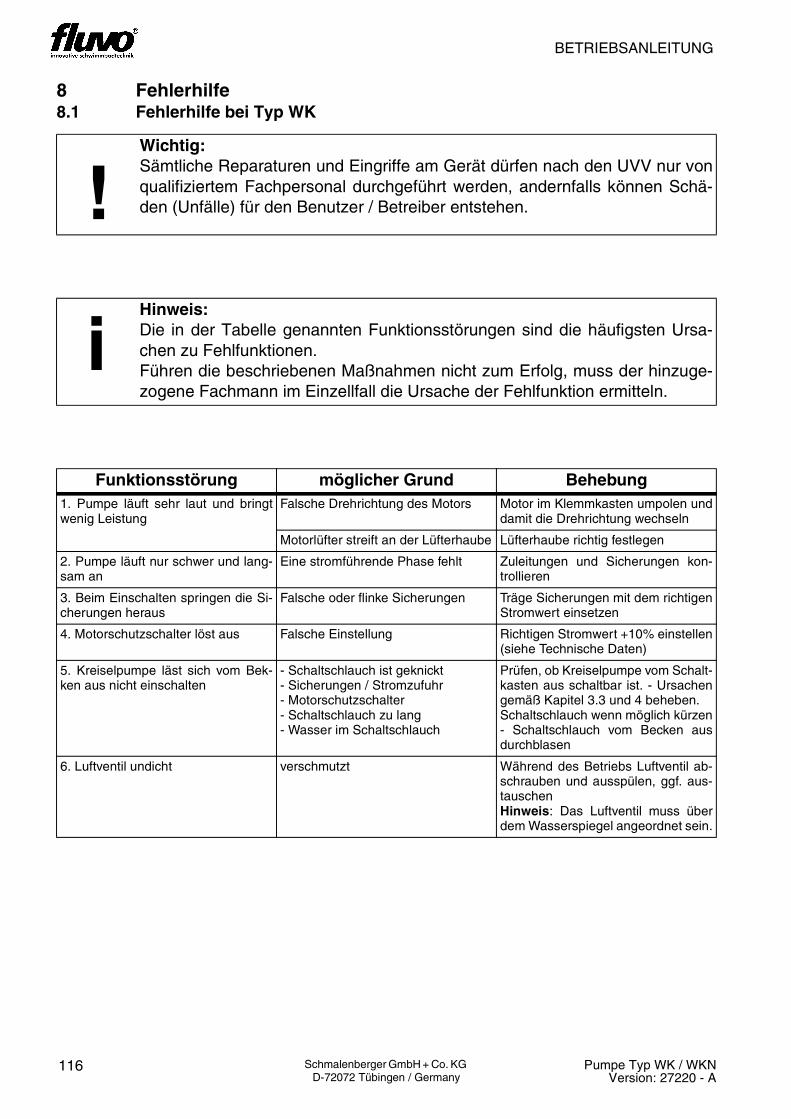
BETRIEBSANLEITUNG
116 Pumpe Typ WK / WKNVersion: 27220 - A
Schmalenberger GmbH + Co. KG D-72072 Tübingen / Germany
8 Fehlerhilfe8.1 Fehlerhilfe bei Typ WK
!Wichtig:Sämtliche Reparaturen und Eingriffe am Gerät dürfen nach den UVV nur vonqualifiziertem Fachpersonal durchgeführt werden, andernfalls können Schä-den (Unfälle) für den Benutzer / Betreiber entstehen.
iHinweis:Die in der Tabelle genannten Funktionsstörungen sind die häufigsten Ursa-chen zu Fehlfunktionen.Führen die beschriebenen Maßnahmen nicht zum Erfolg, muss der hinzuge-zogene Fachmann im Einzellfall die Ursache der Fehlfunktion ermitteln.
Funktionsstörung möglicher Grund Behebung1. Pumpe läuft sehr laut und bringtwenig Leistung
Falsche Drehrichtung des Motors Motor im Klemmkasten umpolen unddamit die Drehrichtung wechseln
Motorlüfter streift an der Lüfterhaube Lüfterhaube richtig festlegen
2. Pumpe läuft nur schwer und lang-sam an
Eine stromführende Phase fehlt Zuleitungen und Sicherungen kon-trollieren
3. Beim Einschalten springen die Si-cherungen heraus
Falsche oder flinke Sicherungen Träge Sicherungen mit dem richtigenStromwert einsetzen
4. Motorschutzschalter löst aus Falsche Einstellung Richtigen Stromwert +10% einstellen(siehe Technische Daten)
5. Kreiselpumpe läst sich vom Bek-ken aus nicht einschalten
- Schaltschlauch ist geknickt- Sicherungen / Stromzufuhr- Motorschutzschalter- Schaltschlauch zu lang- Wasser im Schaltschlauch
Prüfen, ob Kreiselpumpe vom Schalt-kasten aus schaltbar ist. - Ursachengemäß Kapitel 3.3 und 4 beheben. Schaltschlauch wenn möglich kürzen- Schaltschlauch vom Becken ausdurchblasen
6. Luftventil undicht verschmutzt Während des Betriebs Luftventil ab-schrauben und ausspülen, ggf. aus-tauschenHinweis: Das Luftventil muss überdem Wasserspiegel angeordnet sein.

NOTICE D´UTILISATION
117Pumpe Typ WK / WKNVersion: 27220 - A
Schmalenberger GmbH + Co. KG D-72072 Tübingen / Germany
8 Aide aux défauts8.1 Aide aux défauts pour le type WK
!Important:Selon la réglementation UVV (prévention des accidents du travail), l’exécutionde l’ensemble des réparations et interventions sur l’appareil est exclusivementréservée à des spécialistes qualifiés, le contraire risquant d’entraîner desendommagements (accidents) pour l’utilisateur / l’exploitant.
iIndication:Les perturbations de fonctionnement figurant dans le tableau sont les causesles plus fréquentes impliquant des dysfonctionnements.Si les mesures décrites sont appliquées sans succès, solliciter l’aide d’unspécialiste qui identifiera l’origine de dysfonctionnement de ces casparticuliers.
Perturbation du fonctionnement
Cause possible Remède
1. Marche bruyante de la pompe quifournit une puissance insuffisante
Faux sens de rotation du moteur Permuter les pôles dans le boîtier àbornes et inverser de ce fait le sensde la rotation
Le ventilateur du moteur frotte contrele capot du ventilateur
Fixer correctement le capot duventilateur
2. Le démarrage de la pompe estdifficile et lent
Une phase conductrice de courantmanque
Contrôler les lignes d’alimentation etles fusibles
3. Les fusibles sautent à la mise soustension
Faux fusibles ou coupe-circuits àaction instantanée
Utiliser des fusibles à action retardéeà valeur de courant correcte
4. Le contacteur-disjoncteur sedéclenche
Réglage incorrect Régler la valeur de courant correcte+10% (voir Caractéristiquestechniques)
5. La mise en service de la pompecentrifuge est impossible depuis lebassin
- Le tuyau de commande est plié- Fusibles / alimentation en courant- Contacteur-disjoncteur- Tuyau de commande trop long- Présence d’eau dans le tuyau decommande
Vérifier si la pompe centrifuge peutêtre connectée depuis le coffretélectrique. - Remédier aux causesselon les chapitres 3.3 et 4 . Si possible, raccourcir le tuyau decommande- Purger le tuyau de commandedepuis le bassin
6. Valve à air non étanche encrassée Pendant l’exploitation, dévisser lavalve à air et la rincer, le cas échéantla remplacerInformation: La valve à air doit êtrepositionnée au-dessus du niveaud’eau.

OPERATOR’S MANUAL
118 Pumpe Typ WK / WKNVersion: 27220 - A
Schmalenberger GmbH + Co. KG D-72072 Tübingen / Germany
8 Fault Assistance8.1 Fault assistance for type WK
!Important:In accordance with UVV (Accident Prevention Regulations) all repairs andintervention to the unit must be carried out exclusively by qualified personsotherwise damage (accidents) could result to the user / operator.
iInformation:The functional faults listed in the table are the most frequent causes of defects. If the corrective measures described are not successful, then the specialist thatis called in individual cases will have to investigate the cause of the fault.
Functional fault Possible cause Remedy1. Pump runs very loudly and lacksperformance
Motor rotating in the wrong direction Re-pole the motor in the terminal boxand reverse the direction
Motor blower brushes against theblower cover
Fasten the blower cover properly
2. Pump starts up heavily and slowly A current phase is missing Check supplies and fuses
3. The fuses jump out when the pumpis switched on
Wrong or too nimble fuses Insert passive fuses with the correctcurrent rating
4. Motor protection switch trips Wrong setting Set correct current value +10% (seeTechnical Data)
5. Centrifugal pump cannot beswitched on from the pool
- Switching tube has a kink in it- Fuse / power supply- Motor protection switch- Switching tube too long- Water in the switching tube
Check whether centrifugal pump canbe switched from the switchgear box.Eliminate the causes in accordancewith chapters 3.3 and 4 . Shorten switching tube, if possible.- Blow through the switching tubefrom the swimming pool end
6. Air valve leaks Dirty Screw the air valve off and wash it outduring normal operation. Replace it, ifnecessary.Note: The air valve must be locatedabove the water surface.

119Pumpe Typ WK / WKNVersion: 27220 - A
Schmalenberger GmbH + Co. KG D-72072 Tübingen / Germany
BETRIEBSANLEITUNG / NOTICE D´UTILISATION / OPERATOR´S MANUAL

BETRIEBSANLEITUNG
120 Pumpe Typ WK / WKNVersion: 27220 - A
Schmalenberger GmbH + Co. KG D-72072 Tübingen / Germany
8.2 Fehlerhilfe bei Typ WKN
!Wichtig:Sämtliche Reparaturen und Eingriffe am Gerät dürfen nach den UVV nur vonqualifiziertem Fachpersonal durchgeführt werden, andernfalls können Schä-den (Unfälle) für den Benutzer / Betreiber entstehen.
iHinweis:Die in der Tabelle genannten Funktionsstörungen sind die häufigsten Ursa-chen zu Fehlfunktionen.Führen die beschriebenen Maßnahmen nicht zum Erfolg, muss der hinzuge-zogene Fachmann im Einzellfall die Ursache der Fehlfunktion ermitteln.
Achtung:Wenn eine oder mehrere LEDs auf Grund eines Fehlers leuchten, erlöschendiese nicht, wenn der Hauptschalter „AUS“ und wieder „EIN“ geschaltet wird.Erst wenn die Kreiselpumpe gestartet wird, erlöschen die LEDs.
iHinweis:Ist die Pumpe am Netz angeschlossen und es leuchtet keine LED ist die Pum-pe betriebsbereit. Leuchtet die LED "EIN" ist die Pumpe in Betrieb und es liegtkeine Störung an.Die Pumpe ist nach einer durch die LED angezeigte Funktionsstörung nach ca.10 Sekunden wieder betriebsbereit. Sollte die Funktionsstörung nicht behobensein, erleuchtet die LED erneut und die Pumpe schaltet ab. Nach behobenerFunktionsstörung und Wiedereinschalten erlischt die LED.
Betriebsüberwachung
Drehfeldüberwachung
Batterieprüfung Sender
Trockenlauf
Motorschutz
8202
32

BETRIEBSANLEITUNG
121Pumpe Typ WK / WKNVersion: 27220 - A
Schmalenberger GmbH + Co. KG D-72072 Tübingen / Germany
Funktionsstörung möglicher Grund Behebung1. LED „Batterie“ leuchtet Batterie des Senders (19) zu
schwachSender (19) austauschen.LED „Batterie“ erlischt bei ausreichen-der Senderleistung.Hinweis: Sender (19) muss zur Über-winterung bei Raumtemperatur gelagert werden.
2. LED „Drehfeld“ leuchtet Falsche Drehrichtung des Motors Hauptschalter auf „AUS“.Im Klemmenkasten 2 Aussenleiter-Pha-sen umpolen.Hauptschalter auf „EIN“.
Netzzuleitung ist nicht korrekt ange-klemmt
Hauptschalter auf „AUS“.Vergewissern Sie sich, dass alle Aus-senleiter und bei 1~ Motoren der Nulllei-ter angeklemmt sind.Hauptschalter auf „EIN“.
3. LED „Trockenlauf“ blinkt Es ist zu wenig Wasser in der Pumpe.
Pumpe unter Beckenwasserspiegel montieren.Saug- und druckseitig alle Absperror-gane öffnen.
Saugleitung ist verschmutzt bzw. verstopft.
Saugleitung reinigen.
4. LED „Motorschutz“ blinkt Motor ist überlastet Hauptschalter auf „AUS“. Motorlüfter auf Leichtgängigkeit prüfen.Falls notwendig: Pumpe demontieren und Schmutzpartikel aus dem Pumpen-gehäuse entfernen.Hauptschalter auf „EIN“.
5. LED „Motorschutz“ leuchtet Motor ist überhitzt Für ausreichende Kühlluftzufuhr im Pumpenschacht sorgen.
6. Beim Einschalten springen die Sicherungen heraus
Falsche oder flinke Sicherungen Träge Sicherungen mit dem richtigen Stromwert einsetzen
7. Pumpe läuft sehr laut Motorlüfter streift an der Lüfter-haube
Motorlüfter gangbar machen und Lüfter-haube richtig befestigen.
8. Kreiselpumpe lässt sich nicht ein-schalten (Funkansteuerung).
Abstand Sender / Antenne zu groß Verkürzen Sie den lichten Abstand zwi-schen Sender und Antenne auf max. 1 m.
Sende- und Empfängeradresse stimmen nicht überein
- Sendeadresse auf der Rückseite des Senders (19) überprüfen (A00= Adresse 0)- Empfängerdadresse überprüfen (siehe Kapitel 4.4.4)
Batterie des Senders (19) leer Sender (19) austauschen.Hinweis: Sender (19) muss zur Über-winterung bei Raumtemperatur gelagert werden.
9. Kreiselpumpe lässt sich nicht ein-schalten (Pneumatische Ansteuerung)
Schaltschlauch zu lang. Schaltschlauch kürzen auf max. Länge von 8 m.
10.Kreiselpumpe lässt sich nicht einschalten (Externe Ansteue-rung)
Schalter defekt Schalteinheit zum Ein- / Ausschalten der Pumpe sowie Leitungen überprüfen und ggf. ersetzen.
11.Luftventil (28) ist undicht Verschmutzt Während des Betriebs Luftventil abschrauben und ausspülen, ggf. austauschenHinweis: Das Luftventil muss über dem Wasserspiegel montiert sein.

NOTICE D’UTILISATION
122 Pumpe Typ WK / WKNVersion: 27220 - A
Schmalenberger GmbH + Co. KG D-72072 Tübingen / Germany
8.2 Aide aux défauts pour le type WKN
!Important:Selon la réglementation UVV (prévention des accidents du travail), l’exécutionde l’ensemble des réparations et interventions sur l’appareil est exclusivementréservée à des spécialistes qualifiés, le contraire risquant d’entraîner desendommagements (accidents) pour l’utilisateur / l’exploitant.
iIndication:Les perturbations de fonctionnement figurant dans le tableau sont les causesles plus fréquentes impliquant des dysfonctionnements.Si les mesures décrites sont appliquées sans succès, solliciter l’aide d’unspécialiste qui identifiera l’origine du dysfonctionnement de ces casparticuliers.
Attention:Lorsque’une ou plusieurs LED sont allumées pour cause de défaut et nes’éteignent pas lorsque l’interrupteur principal est commuté sur “ARRET”, puisà nouveau sur “MARCHE”. Ces LED ne s’éteignent que lorsque le démarragede la pompe centrifuge s’effectue.
iIndication:Si la pompe est raccordée au secteur et qu’aucune LED n’est allumée, lapompe est alors en état de fonctionnement. Si la LED "MARCHE" est allumée,la pompe est alors en service sans aucune perturbation.La pompe est à nouveau en état de fonctionnement env. au bout des 10secondes qui suivent l’affichage d’une perturbation de fonctionnement par lebiais de la LED. S’il n’a pas été remédié à cette perturbation defonctionnement, la LED s’allume à nouveau et la pompe est mise hors circuit.Après l’élimination de la perturbation de fonctionnement et la remise en circuit,la LED s’éteint.
Surveillance du champ tournant
Contrôle de batterie émetteur
Surveillance du fonctionnement
Marche à sec
Protection moteur
8202
33

NOTICE D´UTILISATION
123Pumpe Typ WK / WKNVersion: 27220 - A
Schmalenberger GmbH + Co. KG D-72072 Tübingen / Germany
Perturbation du fonctionnement
Cause possible Remède
1. La LED „Batterie“ est allumée
Batterie de l’émetteur (19) trop faible
Remplacer l’émetteur (19).La LED „Batterie“ s’éteint lorsque la puissance de l’émetteur est suffisante.Information: Pour la mise en hivernage, entreposer l’émetteur (19) à température ambiante.
2. La LED „Sens de rotation“ est allumée
Faux sens de rotation du moteur Interrupteur principal tourné sur „ARRET“.Permuter les pôles des 2 phases du conducteur extérieur dans le boîtier à bornes.Interrupteur principal tourné sur „MARCHE“.
La ligne d’alimentation secteur n’est pas correctement branchée sur les bornes
Interrupteur principal tourné sur „ARRET“.S’assurer que tous les conducteurs extérieurs et le conducteur neutre des moteurs 1~ sont branchés sur les bornes.Interrupteur principal tourné sur „MARCHE“.
3. La LED „Marche à sec“ clignote
Pas assez d’eau dans la pompe. Monter la pompe sous le niveau d’eau du bas-sin.Ouvrir tous les organes d’arrêt côté aspiration et côté refoulement.
Le conduit d’aspiration est encrassé, voire bouché.
Nettoyer le conduit d’aspiration.
4. La LED „Protection moteur“ clignote
Le moteur est surchargé Interrupteur principal sur „ARRET“. Contrôler la liberté de mouvement du ventilateur du moteur.Si nécessaire : Démonter la pompe et enlever les particules de salissures du carter de la pompe.Interrupteur principal sur „MARCHE“.
5. La LED „Protection moteur“ est allumée
Le moteur a surchauffé Prendre les mesures nécessaires pour une amenée suffisante en air de refroidissement dans la le canal de la pompe.
6. Les fusibles sautent à la mise sous tension
Faux fusibles ou coupe-circuit à action instantanée
Utiliser des fusibles à action retardée à valeur de courant correcte
7. Marche très bruyante de la pompe
Le ventilateur du moteur frotte contre le capot du ventilateur
Assurer la liberté de mouvement du ventilateur du moteur et fixer correctement le capot du ventilateur.
8. La mise en circuit de la pompe est impossible (commande radio).
Ecart émetteur / antenne trop grand
Raccourcir l’écartement entre l’émetteur et l’antenne à une valeur maximale de 1 m.
L’adresse d’émission et celle du récepteur ne coïncident pas
- Vérifier l’adresse d’émission au dos de l’émetteur (19) (A00= Adresse 0)- Vérifier l’adresse du récepteur (voir chapitre 4.4.4)
La batterie de l’émetteur est vide (19)
Remplacer l’émetteur (19).Information: Pour la mise en hivernage, entreposer l’émetteur (19) à température ambiante.
9. La mise en circuit de la pompe est impossible (Commande pneumatique)
Tuyau de commutation trop long. Raccourcir le tuyau de commutation à une lon-gueur max. de 8 m.
10.La mise en circuit de la pompe est impossible (commande externe)
Interrupteur défectueux Contrôler l’unité de mise en contact pour la mise en / hors circuit de la pompe ainsi que les lignes et le cas échéant les remplacer.
11.Valve à air (28) non étan-che
encrassée Pendant l’exploitation, dévisser la valve à air et la rincer, le cas échéant la remplacerInformation: La valve à air doit être positi-onnée au-dessus du niveau d’eau.
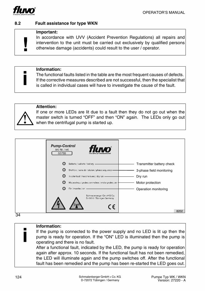
OPERATOR’S MANUAL
124 Pumpe Typ WK / WKNVersion: 27220 - A
Schmalenberger GmbH + Co. KG D-72072 Tübingen / Germany
8.2 Fault assistance for type WKN
!Important:In accordance with UVV (Accident Prevention Regulations) all repairs andintervention to the unit must be carried out exclusively by qualified personsotherwise damage (accidents) could result to the user / operator.
iInformation:The functional faults listed in the table are the most frequent causes of defects. If the corrective measures described are not successful, then the specialist thatis called in individual cases will have to investigate the cause of the fault.
Attention:If one or more LEDs are lit due to a fault then they do not go out when themaster switch is turned “OFF” and then “ON” again. The LEDs only go outwhen the centrifugal pump is started up.
iInformation:If the pump is connected to the power supply and no LED is lit up then thepump is ready for operation. If the “ON” LED is illuminated then the pump isoperating and there is no fault.After a functional fault, indicated by the LED, the pump is ready for operationagain after approx. 10 seconds. If the functional fault has not been remedied,the LED will illuminate again and the pump switches off. After the functionalfault has been remedied and the pump has been re-started the LED goes out.
8202
3-phase field monitoring
Operation monitoring
Dry run
Motor protection
Transmitter battery check
34

OPERATOR’S MANUAL
125Pumpe Typ WK / WKNVersion: 27220 - A
Schmalenberger GmbH + Co. KG D-72072 Tübingen / Germany
Functional fault Possible cause Remedy1. LED “battery” is illuminated Transmitter (19) battery too weak. Replace transmitter (19).
LED “battery” goes out if the transmit-ter power is sufficient.Note: Transmitter (19) must be stored at room temperature during the winter.
2. LED “Phase sequence” is illuminated
Motor rotating in the wrong direction Set master switch to “OFF”.Re-pole the 2 external conductor pha-ses in the terminal box.Set master switch to “ON”.
Power supply cable incorrectly fitted. Set master switch to “OFF”.Check that all external conductors and for 1~ motors the neutral conductor are properly connected.Set master switch to “ON”.
3. LED “dry run” flashes There is not enough water in the pump.
Install pump under the pool water level.Open all shut-off devices on suction and pressure sides.
Suction pipe is dirty or blocked. Clean suction pipe.
4. LED “motor protection” flashes Motor is overloaded Set master switch to “OFF”. Check that the motor fan runs freely.If necessary: Dismantle pump and remove dirt particles from pump hou-sing.Set master switch to “ON”.
5. LED “motor protection” is illuminated
Motor is overheated. Make sure there is enough supply of cooling air to the pump pit.
6. The fuses jump out when the pump is switched on
Wrong or too nimble fuses Insert passive fuses with the correct current rating.
7. Pump runs very loudly Motor blower brushes against the blower cover
Clear motor blower and fasten blower cover properly.
8. Centrifugal pump cannot be switched on (Radio control).
Transmitter / aerial distance too large
Reduce the line-of-sight distance bet-ween the transmitter and the aerial to a maximum of 1 m.
Transmitter and receiver addresses do not agree.
- Check transmitter address on the rear of the transmitter (19) (A00 = address 0).- Check receiver address. (see chap-ter 4.4.4)
Transmitter (19) battery empty. Replace transmitter (19).Note: Transmitter (19) must be stored at room temperature during the winter.
9. Centrifugal pump cannot be switched on (Pneumatic control).
Switching tube too long. Shorten switching tube to a maximum length of 8 m.
10.Centrifugal pump cannot be switched on (External control).
Switch defective Check switching unit for turning pump on and off as well as conductors and replace, if necessary.
11.Air valve (28) leaks Dirty Screw the air valve off and wash it out during normal operation.Replace if required.Note: The air valve must be installed above the water surface.

BETRIEBSANLEITUNG
126 Pumpe Typ WK / WKNVersion: 27220 - A
Schmalenberger GmbH + Co. KG D-72072 Tübingen / Germany
9 Wartung / Instandsetzung9.1 Allgemeine Hinweise
Der Betreiber hat dafür zu sorgen, dass alle Inspektions-, Wartungs- und Reparaturarbei-ten an der Pumpe nur von autorisiertem und dafür speziell geschultem Personal durchge-führt werden. Er muss sich vergewissern, dass das Personal sich durch eingehendesStudium der Betriebsanleitung ausreichend informiert hat. Wir empfehlen die Erstellung und Einhaltung eines Wartungsplanes. Damit können Sieteure Reparaturen vermeiden und ein störungsfreies und zuverlässiges Arbeiten der Pum-pe erreichen.Bei Reparaturen dürfen nur Original-Ersatzteile verwendet werden. Dies gilt besonders fürdie Gleitringdichtung.Bei Arbeiten am Motor sind die Anleitung des jeweiligen Motorherstellers und die darinenthaltenen Anweisungen zu beachten.
9.2 Wartung / Inspektion
Die nachfolgenden Informationen sollen zur Erstellung eines Wartungsplanes verwendetwerden. Es sind Mindestempfehlungen, die den örtlichen Gegebenheiten des Pumpenein-satzes angepasst und im Bedarfsfall ergänzt werden müssen.
Ständige Kontrolle:
• Förderdaten der Pumpe (Druck, Menge)• StromaufnahmeTägliche Kontrollen:
• Pumpenlauf = ruhig und erschütterungsfrei• Lagertemperatur• Leckage der GleitringdichtungKontrolle / Austausch alle 6 Monate:
• Schrauben auf festen Sitz prüfen
Lebensgefahr!Grundsätzlich sind Arbeiten am Klemmenkasten und der Steuerung der Ma-schine nur bei abgeklemmten elektrischen Anschlüssen oder Freischaltungdurchzuführen, um Gefahren durch Stromschläge zu vermeiden.
Achtung: Verletzungs- und Lebensgefahr!Bei Kontroll- und Wartungsarbeiten ist die Kreiselpumpe vor ungewolltem Ein-schalten zu sichern (Freischalten).
iHinweis:Eine Inspektion der Gleitringdichtung soll im Rahmen der Anlagenrevisionnach 8000 Betriebsstunden durchgeführt werden. Wird die Gleitringdichtungim Rahmen einer Anlagenrevision ausgebaut, soll sie durch eine neue ersetztwerden.

NOTICE D´UTILISATION
127Pumpe Typ WK / WKNVersion: 27220 - A
Schmalenberger GmbH + Co. KG D-72072 Tübingen / Germany
9 Entretien / maintenance9.1 Consignes générales
Il convient à l’exploitant de veiller à ce que l’exécution de tous les travaux de révision,d’entretien et de réparation sur la pompe soit exclusivement réservée à un personnelagréé et spécialement formé à cet effet. Il doit s’assurer que le personnel s’estsuffisamment informé par l’étude de la notice d’utilisation. Nous recommandons la création et le respect d’un plan d’entretien. Ceci vous permettrad’éviter des frais de réparation onéreux et d’assurer un fonctionnement impeccable etfiable de la pompe.N’utiliser que des pièces de rechange d’origine pour les réparations. Cette consigneconcerne particulièrement le joint mécanique.Lors d’interventions sur le moteur , respecter les instructions contenues dans le moded’emploi du constructeur respectif.
9.2 Entretien / révision
Les informations suivantes doivent être utilisées pour la mise au point d’un pland’entretien. Celles-ci sont des recommandations minimales nécessitant d’être adaptéesaux conditions locales d’utilisation de la pompe et d’être complétées si besoin.
Contrôle permanent :
• Caractéristiques de refoulement de la pompe (pression,volume)• Courant consomméContrôle quotidien :
• Marche de la pompe = stable et sans vibration• Température des paliers• Fuite au joint mécaniqueContrôle / remplacement tous les 6 mois :
• Vérifier si les vis sont bien serrées
Danger de mort!Les travaux sur la boîte à bornes et sur la commande de la machine ne doiventtoujours être effectués qu’avec une séparation des raccordements électriquesou une mise hors tension afin d’éviter tout danger d’électrocution.
Attention: Danger de blessure et de mort !Protéger la pompe centrifuge contre toute remise en circuit involontaire(déconnexion) lors des travaux de contrôle et d’entretien.
iIndication:Toute révision du joint mécanique doit être effectuée dans le cadre de larévision de l’installation au bout de 8000 heures de service. Si la révision del’installation nécessite le démontage du joint mécanique, le remplacer par unneuf au remontage.

OPERATOR’S MANUAL
128 Pumpe Typ WK / WKNVersion: 27220 - A
Schmalenberger GmbH + Co. KG D-72072 Tübingen / Germany
9 Maintenance / Repair9.1 General Instructions
The operator must ensure that all maintenance, service and repair work on the pump iscarried out exclusively by authorised and specially trained persons. It must be establishedbeyond doubt that the person has studied the operator’s manual in detail. We recommend the creation and adherence to of a maintenance schedule. That willenable you to avoid expensive repairs and have a reliable and trouble-free pumpoperation.Only original spare parts must be used for repairs. This is particularly important for themechanical seal.If work has to be carried out on the motor the instructions in the manual from the relevantmotor manufacturer must be observed.
9.2 Maintenance / Service
Use the following information to create a maintenance schedule. These arerecommendations of minimum requirements that must be adjusted to local conditions ofuse of the pump and may need amending accordingly.
Continuous checks:
• Centrifugal pump delivery data (pressure, amount)• Power take-upDaily checks:
• Pump running is quiet and vibration free• Bearing temperature• Leakage at the mechanical sealCheck / replace every 6 months
• Screws are tight
Mortal danger!In order to prevent electric shocks, work on the terminal box and the machinecontroller must never be carried out before the electrical connections havebeen isolated or disconnected.
Attention: Mortal danger!The centrifugal pump must be safeguarded against unintentional switching on(be disconnected) if checking or maintenance work is to be undertaken.
iInformation:An inspection of the mechanical seal should be carried out within the scope ofa system check after 8000 hours of operation. If the mechanical seal isremoved during a system check, then it must be replaced by a new one.

129Pumpe Typ WK / WKNVersion: 27220 - A
Schmalenberger GmbH + Co. KG D-72072 Tübingen / Germany
BETRIEBSANLEITUNG / NOTICE D´UTILISATION / OPERATOR´S MANUAL

BETRIEBSANLEITUNG
130 Pumpe Typ WK / WKNVersion: 27220 - A
Schmalenberger GmbH + Co. KG D-72072 Tübingen / Germany
9.2.1 Schmierung und Schmiermittelwechsel
Die Kreiselpumpen des Typs WK / WKN in Standardausführung sind nur im Antriebsmotorgelagert. Die Lager sind auf Lebensdauer ausgelegt und mit einer Dauerfettfüllung verse-hen, die nicht nachgeschmiert werden kann. Defekte Lager müssen ausgetauscht werden.
9.3 Instandsetzung
9.3.1 Allgemein
Führen Sie Instandsetzungsarbeiten nur an der ausgebauten Kreiselpumpe in einer geeig-neten Werkstatt durch. Beachten Sie dabei die allgemeinen Hinweise am Anfang des Kapitels! Diese Anleitung ermöglicht Ihnen, die Pumpe zu zerlegen und mit den notwendigen Neu-teilen wieder fachgerecht zusammenzubauen.
Ansonsten können die Arbeiten mit dem werkstattüblichen Werkzeug vorgenommen wer-den. Spezialwerkzeug ist nicht erforderlich.Säubern Sie nach der Demontage alle Einzelteile der Kreiselpumpe gründlich. Kontrollie-ren Sie die Einzelteile auf Abnutzung und Beschädigung. Nicht einwandfreie Teile müssennachgearbeitet bzw. ersetzt werden.
9.3.2 Demontagevorbereitung
iHinweis:Beachten Sie auch die beigefügte Explosionszeichnung und die Ersatzteilliste!
Achtung:Bei der Montage einer neuen Gleitringdichtung sind besondere Hinweise zubeachten!
Achtung:Vor Beginn der Demontage muss die Pumpe so gesichert werden, dass sienicht eingeschaltet werden kann (Freischalten). Warnhinweis am Schalt-schrank!Bei Anlagenbetrieb den Schichtführer bzw. Vorgesetzten unterrichten.
!Wichtig:Berücksichtigen Sie bei den folgend beschriebenen Arbeiten auch die örtlichenVorschriften und Gegebenheiten.

NOTICE D´UTILISATION
131Pumpe Typ WK / WKNVersion: 27220 - A
Schmalenberger GmbH + Co. KG D-72072 Tübingen / Germany
9.2.1 Lubrification et vidange du lubrifiant
Le modèle standard des pompes centrifuges du type WK / WKN n’est logé que dans lemoteur d’entraînement. Les paliers sont graissés à vie et ne doivent pas être de nouveaulubrifiés. Les paliers défectueux doivent être remplacés.
9.3 Remise en état
9.3.1 Généralités
N’exécuter les travaux de remise en état que sur la pompe centrifuge démontée, dans unatelier approprié. Observer pour cela les consignes générales fournies au début du chapitre ! Les instructions vous permettront de désassembler la pompe et de l’assembler à nouveaucorrectement avec les pièces neuves requises.
Pour le reste, les travaux peuvent être exécutés à l’aide de l’outillage habituel d’un atelier.Des outils spéciaux ne sont pas nécessaires.Après le démontage, nettoyer séparément chacune des pièces de la pompe centrifuge.Contrôler chaque pièce pour déceler des marques d’usure ou des dommages. Les piècesqui ne sont pas dans un état parfait doivent être remises en état ou remplacées.
9.3.2 Préparation du démontage.
iIndication:Observer aussi la vue explosée et la liste des pièce détachées jointes !
Attention:Le montage d’un joint mécanique neuf demande le respect de consignesparticulières !
Attention:Avant le début du démontage, protéger impérativement la pompe centrifugecontre toute remise en circuit (déconnexion). Avertissement sur l’armoireélectrique !Prévenir le supérieur ou le responsable d’équipe lors du fonctionnement del’installation.
!Important:Lors des travaux décrits ci-dessous, respecter aussi les conditions etconsignes locales.

OPERATOR’S MANUAL
132 Pumpe Typ WK / WKNVersion: 27220 - A
Schmalenberger GmbH + Co. KG D-72072 Tübingen / Germany
9.2.1 Lubrication and Changing Lubricants
Centrifugal pumps of the types WK / WKN in the standard models only run on bearings inthe drive motors. The bearings are designed to last the useful life of the motor and arefilled with a grease that cannot be replenished. Defective bearings must be replaced.
9.3 Repair
9.3.1 General
Always carry out repair work on the removed centrifugal pump in an appropriate workshop. Be sure to observe the general instructions at the beginning of the chapter! These instructions will enable you to dismantle the pump and to re-assemble it properlywith the requisite spare parts in place.
Otherwise the work can be undertaken with the usual workshop tools. No special tools areneeded.After dismantling thoroughly clean all the individual parts of the centrifugal pump. Checkthe individual parts for wear and damage. Parts that are not perfect must be reworked orreplaced.
9.3.2 Dismantling Preparations
iInformation:Please also take note of the attached exploded diagram and the spare partslist!
Attention:When a new mechanical seal is fitted special instructions must be observed!
Attention:Prior to starting to dismantle it the pump must be safeguarded againstaccidental switching on (it must be disconnected). Warning on the switchingcabinet!When used in a facility, inform the shift leader or manager.
!Important:For the following work, please be sure to observe local regulations andconditions.

133Pumpe Typ WK / WKNVersion: 27220 - A
Schmalenberger GmbH + Co. KG D-72072 Tübingen / Germany
BETRIEBSANLEITUNG / NOTICE D´UTILISATION / OPERATOR´S MANUAL

BETRIEBSANLEITUNG
134 Pumpe Typ WK / WKNVersion: 27220 - A
Schmalenberger GmbH + Co. KG D-72072 Tübingen / Germany
9.3.3 Demontage / Ausbau der Pumpe
Die Pumpe muss Umgebungstemperatur angenommen haben.
• Stromzuführung unterbrechen• Armaturen schließen (saug- u. druckseite)• Pumpe entleeren durch die Ablaßschraube 11• Motor abklemmen• Vorhandene Zusatzanschlüsse demontieren• Druck- und Saugstutzen lösen• Pumpe von der Grundplatte lösen • Pumpe komplett abheben
!Wichtig:Beachten Sie beim Entleeren der Kreiselpumpe die folgenden Hinweise!
1. Wurde die Pumpe zur Förderung von gesundheitsgefährdenden Flüssig-keiten eingesetzt, so ist beim Entleeren der Pumpe darauf zu achten,dass keine Gefährdung für Personen und die Umwelt entsteht.
2. Sofern erforderlich, Schutzkleidung sowie Schutzmaske tragen!3. Die verwendete Spülflüssigkeit sowie ggf. Restflüssigkeit in der Pumpe
müssen fachgerecht und ohne Gefahr für Personen und Umwelt aufgefan-gen und entsorgt werden.
4. Pumpen, die gesundheitsgefährdende Flüssigkeiten fördern, müssendekontaminiert werden. Beim Ablassen des Fördermediums ist darauf zuachten, dass keine Gefährdung für Personen und Umwelt entsteht.
5. Gesetzliche Bestimmungen sind strikt einzuhalten!
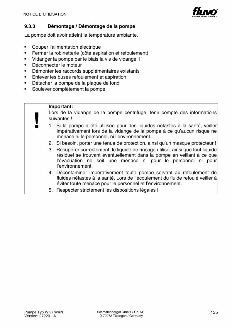
NOTICE D´UTILISATION
135Pumpe Typ WK / WKNVersion: 27220 - A
Schmalenberger GmbH + Co. KG D-72072 Tübingen / Germany
9.3.3 Démontage / Démontage de la pompe
La pompe doit avoir atteint la température ambiante.
• Couper l’alimentation électrique• Fermer la robinetterie (côté aspiration et refoulement)• Vidanger la pompe par le biais la vis de vidange 11• Déconnecter le moteur• Démonter les raccords supplémentaires existants• Enlever les buses refoulement et aspiration• Détacher la pompe de la plaque de fond • Soulever complètement la pompe
!Important:Lors de la vidange de la pompe centrifuge, tenir compte des informationssuivantes !1. Si la pompe a été utilisée pour des liquides néfastes à la santé, veiller
impérativement lors de la vidange de la pompe à ce qu’aucun risque nemenace ni le personnel, ni l’environnement.
2. Si besoin, porter une tenue de protection, ainsi qu’un masque protecteur !3. Récupérer correctement le liquide de rinçage utilisé, ainsi que tout liquide
résiduel se trouvant éventuellement dans la pompe en veillant à ce quel’évacuation ne soit une menace ni pour le personnel ni pourl’environnement.
4. Décontaminer impérativement toute pompe servant au refoulement defluides néfastes à la santé. Lors de l’écoulement du fluide refoulé veiller àéviter toute menace pour le personnel et l’environnement.
5. Respecter strictement les dispositions légales !

OPERATOR’S MANUAL
136 Pumpe Typ WK / WKNVersion: 27220 - A
Schmalenberger GmbH + Co. KG D-72072 Tübingen / Germany
9.3.3 Dismantling / Removal of the Centrifugal Pump
The pump must be allowed to reach room temperature.
• Disconnect the power supply.• Close valves (on the suction and pressure sides).• Empty the pump via the drainage screw 11• Disconnect motor.• Remove existing additional connections.• Release pressure and suction nozzles.• Release pump from its base plate.• Lift pump completely off.
!Important:When emptying the centrifugal pump please observe the following instructions!
1. If the pump was used to deliver liquids that are hazardous to health, thengreat care must be taken in emptying the pump that neither persons northe environment are placed at risk through the process.
2. If necessary, wear protective clothing and protective mask!3. The rinsing liquid used and any residual fluid out of the pump must be
caught and disposed of properly and without placing persons or theenvironment in any danger.
4. Pumps that deliver liquids that are hazardous to health must bedecontaminated. In draining the delivery medium off care must be takenthat neither persons nor the environment are placed in any danger.
5. Legal requirements must be adhered to!

137Pumpe Typ WK / WKNVersion: 27220 - A
Schmalenberger GmbH + Co. KG D-72072 Tübingen / Germany
BETRIEBSANLEITUNG / NOTICE D´UTILISATION / OPERATOR´S MANUAL

BETRIEBSANLEITUNG
138 Pumpe Typ WK / WKNVersion: 27220 - A
Schmalenberger GmbH + Co. KG D-72072 Tübingen / Germany
NOTICE D´UTILISATION
9.4 Demontage / Kreiselpumpe zerlegen
9.4.1 Bevor Sie beginnen
Beginnen Sie die Arbeiten nur wenn Sie überprüft haben:• Dass die benötigten Ersatzeile vorhanden sind und diese zur Pumpe bzw. zu der Ihnen
vorliegenden Variante passen. Oder die noch festzustellenden schadhaften Teile kurz-fristig beschafft werden können.
• Dass Sie alle für die Arbeiten benötigten Werkzeuge und Hilfsmittel zur Verfügung ha-ben.
!Wichtig:Verwenden Sie nur Original Ersatzteile zu den Reparaturen!Die Einhaltung dieses Hinweises ist Voraussetzung für einen störungsfreienBetrieb der Pumpe und die Erfüllung eventueller Garantieansprüche.
Kundendienst
Schmalenberger bietet einen 24 Stunden Service für die Ersatzteillieferung!
9.4 Démontage / Désassemblage de la pompe centrifuge
9.4.1 Avant de commencer
Ne commencer les travaux qu’après avoir vérifié :• que les pièces de rechange requises sont à disposition et que ces dernières sont
adéquates à la pompe voire à la variante de pompe concernée. Ou que les piècesdéfectueuses devant être remplacées peuvent être livrées rapidement.
• Que tous les outils et moyens auxiliaires nécessaires pour les travaux sont disponibles.
!Important:Utiliser uniquement des pièces de rechange d’origine pour les réparations !Le respect de ces consignes est une condition prérequise pour unfonctionnement impeccable de la pompe et l’assurance aux droits de garantieéventuels.
Service Client
Schmalenberger offre un service en 24 heures pour la livraison des pièces derechange !

139Pumpe Typ WK / WKNVersion: 27220 - A
Schmalenberger GmbH + Co. KG D-72072 Tübingen / Germany
OPERATOR´S MANUAL
9.4 Dismantling / Dismantling the Centrifugal Pump
9.4.1 Before you begin
Begin the work only once you have checked that:• The required spare parts are available and that they will fit this pump or your particular
model thereof. Or that the suspected damaged parts can be obtained promptly.• You have all the required tools and accessories for the work.
!Important:Use only original spare parts for the repairs!Observing these instructions is a prerequisite for trouble-free operation of thepump and for the acceptance of potential claims under guarantee.
Customer Service
Schmalenberger provides a 24 hour service for the delivery of spare parts!

BETRIEBSANLEITUNG
140 Pumpe Typ WK / WKNVersion: 27220 - A
Schmalenberger GmbH + Co. KG D-72072 Tübingen / Germany
FLUVO
7961 75.2 1975.134
9.5 Austausch des Sendeknopfes
siehe Abb. 35
Führen Sie das Funkgehäuse (79) nach obenaus der Halteplatte (75.1) heraus. SchraubenSie den Haltedeckel (75.2) vom Funkgehäuse(79) ab.
Nehmen Sie dann den Sendeknopf (19) her-aus und ersetzen ihn durch einen neuen. Befe-stigen Sie den Haltedeckel (75.2) mit Hilfe derBlechschrauben (61) wieder fest am Funkge-häuse (79). Führen Sie danach das Funkge-häuse (79) wieder von oben in die Halteplatte(75.1) ein, bis das Funkgehäuse (79) fest ein-rastet.
19 Sendeknopf34 Klebestreifen61 Blechschrauben75.1 Halteplatte75.2 Haltedeckel79 Funkgehäuse
9.6 Ersatzteilliste / Zeichnung
Auf den Seiten 154 bis 160 finden Sie die Er-satzteilliste und die Explosionszeichnung zuIhrer Kreiselpumpe.Beachten Sie dabei Ihren Pumpentyp und diejeweilige Ausführung.
!Wichtig:Geben Sie die Adressierung z.B.A00 des Sendeknopfes (19) bei derErsatzteilbestellung unbedingt an!
358201

OPERATOR´S MANUALNOTICE D´UTILISATION
141Pumpe Typ WK / WKNVersion: 27220 - A
Schmalenberger GmbH + Co. KG D-72072 Tübingen / Germany
9.5 Replacing the transmitterhead
see fig. 35
Move the wireless housing (79) upwardsout of the mounting plate (75.1). Screw theholder (75.2) off the wireless housing (79).
Then extract the transmitter head (19) andreplace it with a new one. Then take thetransmission button (19) out and replace itwith a new one. Fasten the holder (75.2)with the help of the tapping screws (61)back onto the wireless housing (79). Insertthe wireless housing (79) back into themounting plate (75.1) from above until thewireless housing (79) engages firmly.
19 Transmitter head34 Sticky tape61 Tapping screws75.1 Mounting plate75.2 Holder79 Wireless housing
9.6 Spare Parts List / Drawing
On pages 154 to 160 there is a spare partslist and the exploded diagram of yourcentrifugal pump. Please take note of your pump type and therelevant model.
!Important:Be sure to specify the addressof the transmission button (19),e.g. A00, when ordering as aspare part!
9.5 Remplacement de la têteémettrice
voir fig. 35
Sortir le boîtier radio (79) de la plaque de retenue (75.1) en le tirant vers le haut.Dévisser le couvercle de retenue (75.2) duboîtier radio (79).
Extraire ensuite la tête émettrice (19) et laremplacer par une neuve. Extraire ensuitela tête émettrice (19) et la remplacer parune neuve. A l’aide des vis de tôle (61), re-fixer le couvercle de retenue (75.2) à fondsur le boîtier radio (79). Par le haut, intro-duire ensuite à nouveau le boîtier radio (79)dans la plaque de retenue (75.1) jusqu’audéclic de l’emboîtement ferme dans le boî-tier radio (79).
19 Tête émettrice34 Bande adhésive61 Vis à tôle75.1 Plaque de retenue75.2 Couvercle de retenue79 Boîtier radio
9.6 Liste des pièce détachées /Schéma
Vous trouverez aux pages de 154 à 160, laliste des pièce détachées et la vueexplosée se rapportant à votre pompecentrifuge.Tenez compte du type de votre pompe etde la variante dont il est question.
!Important:Spécifier impérativement l’adressage par ex. A00 de latête émettrice (19) lors de lacommande de piècesdétachées !

142 Pumpe Typ WK / WKNVersion: 27220 - A
Schmalenberger GmbH + Co. KG D-72072 Tübingen / Germany
BETRIEBSANLEITUNG / NOTICE D´UTILISATION / OPERATOR´S MANUAL
10 Anhang10.1 Außerbetriebnahme / Einlagerung / Konservierung
Jede Pumpe verläßt das Werk in sorgfältig montiertem Zustand. Wenn die Inbetriebnahmelängere Zeit nach der Lieferung erfolgen soll, empfehlen wir zur Lagerung der Pumpe diefolgenden Maßnahmen.
10.1.1 Einlagerung neuer Pumpen
Neue Pumpen besitzen, nur wenn gefordert, einen Konservierungsschutz, entsprechendder vom Besteller angegebenen Einlagerungszeit. Wird diese erheblich überschritten, istder Zustand der Pumpe zu überprüfen und ggf. nachzukonservieren.
10 Annexes10.1 Mise hors service / Entreposage / Conservation
Chaque pompe quitte notre usine dans un état minutieusement monté. Si la mise enservice devait s’effectuer longtemps après la livraison, nous recommandons de stocker lapompe en appliquant les mesures suivantes.
10.1.1 Entreposage de pompes neuves
Les pompes neuves ne sont pourvues d’une protection conservatrice que sur demande eten fonction de la durée de entreposage spécifiée par le commanditaire. Si ce délai estexcessivement dépassé, contrôler l’état de la pompe et au besoin renouveler la protectionconservatrice.
10 Appendix10.1 Shutdown / Storage / Conservation
Every pump leaves the factory carefully assembled. If initial operation is predicted to be along time after delivery we recommend the following measures for storage of thecentrifugal pump.
10.1.1 Storage of new Pumps
When requested, new pumps receive a conservation protection corresponding to thestorage time stated by the purchaser. If this period of time is considerably exceeded thecondition of the pump must be checked and, if required, re-conserved.

143Pumpe Typ WK / WKNVersion: 27220 - A
Schmalenberger GmbH + Co. KG D-72072 Tübingen / Germany
BETRIEBSANLEITUNG / NOTICE D´UTILISATION / OPERATOR´S MANUAL
10.1.2 Längere Außerbetriebnahme > 3 Monate
1. Pumpe bleibt eingebaut
Um eine stete Betriebsbereitschaft sicherzustellen und um die Bildung von Ablagerungenim Pumpeninnenbereich und im unmittelbaren Pumpenzuflußbereich zu vermeiden, solldas Pumpenaggregat bei längerer Stillstandszeit turnusmäßig monatlich bis vierteljährlich,kurzzeitig (ca. 15 Minuten) einem Funktionslauf unterzogen werden. Voraussetzung ist,dass der Pumpe ausreichend Flüssigkeit zugeführt werden kann.
2. Pumpe wird ausgebaut und eingelagert
Gehen Sie zum Ausbau der Pumpe nach den Maßnahmen des Kapitel 9. Wartung/In-standhaltung vor. Vor Einlagerung der Pumpe ist diese gründlich zu reinigen und zu konservieren. Es musseine Außen- u. Innenkonservierung vorgenommen werden.
10.1.2 Mise hors service prolongée > 3 mois
1. La pompe reste intégrée
Pour garantir une disponibilité permanente et pour éviter la formation de dépôts à l’intérieurde la pompe et dans la zone d’admission immédiate de la pompe, il est conseillé –lorsd’arrêt de plus longue durée - de soumettre pendant une brève durée (env. 15 minutes) legroupe moto-pompe à une marche de fonctionnement se répétant régulièrement une foispar mois ou au moins tous les trois mois.. Condition prérequise : la pompe doit pouvoir êtresuffisamment alimentée en liquide.
2. La pompe est démontée et est mise en stock
Pour le démontage de la pompe, suivre les mesures fournies au Chapitre 9. Entretien/Remise en état. Avant de mettre la pompe en stock, la nettoyer et la conserver minutieusement. Procéderà une conservation interne et externe.
10.1.2 Longer Periods of Shutdown > 3 months
1. Pump remains installed
To ensure that the pump is always ready for operation and to prevent the formation ofdeposits inside the pump and in its immediate vicinity, the pump aggregate should be runfor a short time (approx. 15 minutes) monthly or quarterly during longer periods ofinactivity. Prerequisite for this is that sufficient fluid is supplied to the pump.
2. Pump is removed and stored
To remove the pump proceed as outlined in chapter 9 “Maintenance / Repair”. Prior to storing the pump it must be thoroughly cleaned and conserved. Conservation mustbe done both internally and externally.
BETRIEBSANLEITUNG
144 Pumpe Typ WK / WKNVersion: 27220 - A
Schmalenberger GmbH + Co. KG D-72072 Tübingen / Germany
10.1.3 Wiederinbetriebnahme nach Einlagerung
Entkonservierung
Vor dem Einbau der eingelagerten Pumpe muss das aufgebrachte und/oder eingefüllteKonservierungsmittel entfernt werden. Gehen Sie dabei wie im Kapitel 3.2.2 Reinigen be-schrieben vor.Überprüfen Sie nach längerer Lagerzeit unter Konservierungsbedingungen die Formstabi-lität der Elastomere (O-Ringe, Gleitringdichtungen) auf ihre Formelastizität. VersprödeteElastomere sind auszutauschen.
Wiederinbetriebnahme
Die ausgebaute Pumpe nach den im Kapitel 3.3 Aufstellen und Anschließen beschrie-benen Vorgehen wieder einbauen.
Vor Wiederinbetriebnahme der eingebauten Pumpe sind die Überprüfungen und War-tungsmaßnahmen gemäß Kapitel 9.2 durchzuführen. Für den erneuten Einsatz müssenaußerdem die im Abschnitt Erstinbetriebnahme (7.1) genannten Punkte beachtet werden.
Besonderheit der Gleitringdichtungen:
Gleit- und Gegenring können auf Grund von Adhäsionskräften sehr stark aufeinander haf-ten. Der Kraftschluss der Mitnahmefeder reicht dann nicht mehr aus, um den Gleitring los-zubrechen. In diesem Falle läuft die Welle in den feststehenden Dichtungen und derMitnahmefeder, was zu Schäden führt. Nehmen Sie die Lüfterhaube ab und drehen Sie amLüfterrad in die Richtung des Drehrichtungspfeils. Stellt sich Wiederstand ein und federtdas Lüfterrad zurück muß die Gleitringdichtung ausgebaut und Gleit- und Gegenring vor-sichtig getrennt werden. Versuchen Sie nicht die Welle mit Gewalt durchzudrehen.
!Wichtig:Unmittelbar nach Abschluss der Arbeiten müssen alle Sicherheits- undSchutzeinrichtungen fachgerecht angebracht bzw. in Funktion gesetzt werden.
iWichtig:Vor Erstinbetriebnahme und nach längerer Stillstandszeit bzw. nach Einbau ei-ner neuen Gleitringdichtung unbedingt die Leichtgängigkeit prüfen.

NOTICE D´UTILISATION
145Pumpe Typ WK / WKNVersion: 27220 - A
Schmalenberger GmbH + Co. KG D-72072 Tübingen / Germany
10.1.3 Remise en service après entreposage
Suppression de la conservation
Avant d’intégrer la pompe mise en stock, éliminer le moyen de conservation appliqué et/ou rempli. Procéder pour cela en suivant la description fournie au chapitre 3.2.2Nettoyage.Après une période d’entreposage prolongée sous conditions de conservation, contrôler lastabilité de forme de l’élastomère (joints toriques, joints mécaniques) au niveau de sonélasticité. Remplacer les élastomères ayant perdu leur élasticité.
Remise en service
Réintégrer la pompe démontée en suivant la description fournie au chapitre 3.3 Mise enplace et raccordement .
Avant la remise en service de la pompe intégrée, procéder à des contrôles et à desmesures d’entretien conformément au chapitre 9.2. Pour l’utilisation renouvelée, respecteren outre les points mentionnés au chapitre de la première mise en service (7.1).
Particularité des joints mécaniques:
En raison de leurs fortes forces d’adhérence, le joint mécanique et le contre-anneaurisquent de rester collés l’un à l’autre. L’adhérence du ressort entraîneur ne suffit alors pluspour détacher le joint mécanique. Dans ce cas, l’arbre circule dans les joints immobiliséset le ressort entraîneur, entraînant alors des dommages. Retirer le capot du ventilateur ettourner le volant du ventilateur dans le sens de la flèche du sens de rotation. En cas derésistance et si la roue du ventilateur revient élastiquement en arrière, démonter le jointmécanique et séparer celui-ci avec prudence du contre-anneau. Ne pas essayer de fairetourner l’arbre en forçant.
!Important:A l’issue des travaux, immédiatement apposer et remettre en fonction tous lesdispositifs de sécurité et de protection de manière professionnelle.
iIndication:Avant la première mise en service, après une période d’arrêt prolongée voireaprès le montage d’un joint mécanique neuf, vérifier impérativement ladouceur du fonctionnement.

OPERATOR’S MANUAL
146 Pumpe Typ WK / WKNVersion: 27220 - A
Schmalenberger GmbH + Co. KG D-72072 Tübingen / Germany
10.1.3 Restarting after Periods of Storage
De-conservation
Before the stored pump is re-installed the conservation agent (covering or filling) must beremoved. Proceed as described in chapter 3.2.2 “Cleaning”.After long periods of storage under conservation conditions check the shape stability andelasticity of the Elastomers (O-rings and mechanical seals). Brittle rings must be replaced.
Restarting
Re-install the pump according to the procedure described in chapter 3.3 “Installing andConnecting” .
Before the pump is re-started the checks and maintenance measures stated in chapter 9.2must be carried out. For the new re-start the points listed in section 7.1 “Initial Start-up”must also be observed.
Particularities of the mechanical seal:
The sliding ring and its counterpart ring can stick together very firmly due to adhesiveforces. The force of the driving spring is then not enough to break the sliding ring away.In this case the shaft runs in the static seals and the driving spring, which leads to damage.Remove the blower cover and turn the blower wheel in the direction of the arrow. If thereis resistance and the blower wheel feathers back then the mechanical seal has to beremoved and the sliding ring and its counterpart ring must be carefully separated. Underno circumstances should the shaft be turned by force.
!Important:Immediately after completing the above work, all safety and protectivemeasures must be properly installed and checked that they function.
iInformation:Prior to an initial start-up and after longer periods of standstill or after a newmechanical seal is installed it is important to check that the pump runs freely.

147Pumpe Typ WK / WKNVersion: 27220 - A
Schmalenberger GmbH + Co. KG D-72072 Tübingen / Germany
BETRIEBSANLEITUNG / NOTICE D´UTILISATION / OPERATOR´S MANUAL

BETRIEBSANLEITUNG
148 Pumpe Typ WK / WKNVersion: 27220 - A
Schmalenberger GmbH + Co. KG D-72072 Tübingen / Germany
NOTICE D´UTILISATION
10.2 Entsorgung
!Wichtig:Wollen Sie die Pumpe endgültig stillegen und aus dem Betrieb entfernen, dannbeachten Sie die örtlichen Vorschriften zur Entsorgung von Industrieabfällen.
Achtung: Lebensgefahr / Vergiftungsgefahr!Pumpen, die giftige, ätzende oder sonstige chemische Stoffe, die eine Gefahrfür Mensch und Tier bilden, gefördert haben, müssen vor der Entsorgunggründlich gereinigt und/oder dekontaminiert werden.Auch die Reinigungsmittel und Reste des Fördermediums sind entsprechendder gesetzlichen Vorschriften zu handhaben.Falls in der Region des Betreibers der Pumpe entsprechende ges. Vorschriftenbestehen, ist die Pumpe zu zerlegen und die verschiedenen Materialien zutrennen, um diese getrennt zu entsorgen.
10.2 Mise au rebut
!Important:Voulez-vous mettre définitivement la pompe à l’arrêt et hors d’activité,observez alors les règlements locaux relatifs à l’évacuation de déchetsindustriels.
Attention: Danger de mort / Risque d’empoisonnement !Toutes les pompes ayant refoulé des substances toxiques, corrosives oud’autres substances chimiques représentant une menace pour les personneset les animaux doivent impérativement être méticuleusement nettoyées et/oudécontaminées avant d’être mises au rebut.Il convient également de manipuler les produits de nettoyage et les restes defluide refoulé en respectant les dispositions légales appropriées.Si dans la région de l’exploitant il existe des dispositions légales concernant letri des matériaux, désassembler la pompe, séparer les matériaux puis lesévacuer vers la gestion des déchets concernée.

149Pumpe Typ WK / WKNVersion: 27220 - A
Schmalenberger GmbH + Co. KG D-72072 Tübingen / Germany
OPERATOR´S MANUAL
10.2 Disposal
!Important:If you want to take the pump completely out of service and never re-use it thenplease observe the local regulations for the disposal of industrial waste.
Attention: Mortal danger / poison!Pumps that have delivered poisonous, caustic or other chemical substanceswhich are hazardous to the health of people and animals must be thoroughlycleaned and / or decontaminated prior to being disposed of. The cleaning agents and rests of the delivery medium must also be handled inaccordance with legal requirements. If such legal regulations exist in the area where the pump is operated then thepump must be completely dismantled and sorted into the different materials sothat they can be disposed of separately.

150 Pumpe Typ WK / WKNVersion: 27220 - A
Schmalenberger GmbH + Co. KG D-72072 Tübingen / Germany
BETRIEBSANLEITUNG / NOTICE D´UTILISATION / OPERATOR´S MANUAL
10.3 Wichtige Hinweise
10.3.1 Werksreparatur
Beachten Sie die folgenden Hinweise bei einer Rücklieferung der Pumpe zur Reparatur:1. Wenn Sie die Pumpe zur Reparatur oder Nachrüstung in das Herstellerwerk senden,
dann fügen Sie der Lieferung genaue Angaben über das mit der Pumpe geförderte Me-dium bei.
2. Sind die geförderten Medien giftig, ätzend usw. fügen Sie unbedingt eine Kopie des Si-cherheitsblatts zu den Medien bei!
3. Es können nur vollständig entleerte und gereinigte Pumpen zur Reparatur angenom-men.
10.3 Informations importantes
10.3.1 Réparation d’usine
Lors du renvoi de la pompe à l’usine pour réparation, tenir compte des informationssuivantes :1. Lorsque la pompe est retournée à l’usine du constructeur pour cause de réparation ou
d’équipement complémentaire, joindre à la livraison des indications précisesconcernant le fluide refoulé avec la pompe.
2. Si les fluides refoulés sont toxiques, corrosifs etc., joindre impérativement la feuilletechnique de sécurité se rapportant à ces fluides !
3. Seules les pompes entièrement vidées et nettoyées seront acceptées pour la répara-tion.
10.3 Important Instructions
10.3.1 Factory repair
Please observe the following instructions if the pump is sent back to the factory for repair:1. If you send the pump back to the manufacturer for repair or an upgrade then please be
sure to enclose precise details of the media that were delivered by the pump. 2. If the delivered media were poisonous, caustic, etc. then please be sure to enclose a
copy of the safety sheet for the media! 3. Only pumps that are completely empty and clean will be accepted for repair.

151Pumpe Typ WK / WKNVersion: 27220 - A
Schmalenberger GmbH + Co. KG D-72072 Tübingen / Germany
BETRIEBSANLEITUNG / NOTICE D´UTILISATION / OPERATOR´S MANUAL
10.3.2 Ordering Spare Parts
When ordering spare parts please do not fail to give us the following important information:• Pump serial number and type description or alternatively the motor serial number• Delivery medium• Part number from the spare parts list• Part description• Material data from the specifications or the order confirmation
The pump serial number is on the type plate which is fastened to the blower cover of themotor.
The order confirmation or motor serial number may also be of assistance.With this information you make it much easier for us to deliver the correct spare part foryour pump!
10.3.2 Ersatzteilbestellung
Geben Sie bei der Bestellung von Ersatzteilen unbedingt folgende wichtige Daten an:• Pumpennummer und Typenbezeichnung, alternativ die Motornummer• Fördermedium• Positionsnummer aus der Ersatzteilliste• Benennung des Teils• Werkstoffangaben aus der Spezifikation bzw. der Auftragsbestätigung
Sie finden die Pumpennummer auf dem Typenschild, das auf der Lüfterhaube des Motorsbefestigt ist.
Darüber hinaus kann auch die Auftragsbestätigung oder die Motornummer weiterhelfen.Sie erleichtern uns damit die Lieferung des richtigen Ersatzteils für Ihre Pumpe!
10.3.2 Commande de pièces de rechange
Lors de la commande toujours spécifier les éléments importants suivants :• le numéro de la pompe, la désignation du type, ou bien en alternative le numéro du
moteur• le fluide de refoulement• le numéro de position dans la liste de pièces détachées• la désignation de la pièce• les indication du matériau issues de la spécification et de la confirmation de commande
Vous trouverez le numéro de la pompe sur la plaquette signalétique fixée sur le capot duventilateur du moteur.
Le numéro de moteur ou la confirmation de commande peuvent aussi être utiles.Vous nous faciliterez le travail et assurez ainsi la livraison de la bonne pièce de rechangede votre pompe !

BETRIEBSANLEITUNG
152 Pumpe Typ WK / WKNVersion: 27220 - A
Schmalenberger GmbH + Co. KG D-72072 Tübingen / Germany
NOTICE D´UTILISATION
Siehe Homepage unter: www.schmalenberger.de
Anschrift des Stammhauses:Schmalenberger GmbH+Co. KG
Postfach 2380D-72013 Tübingen
Telefon:+ 49 (0) 7071 - 7008-0Telefax:+ 49 (0) 7071 - 7008-59
Kundendienst
Schmalenberger bietet einen 24 Stunden Service für die Ersatzteillieferung!
Voir notre page d’accueil sous : www.schmalenberger.de
Adresse de la maison-mère :Schmalenberger GmbH+Co. KG
Postfach 2380D-72013 Tübingen
Téléphone:+ 49 (0) 7071 - 7008-0Fax:+ 49 (0) 7071 - 7008-59
Service Client
Schmalenberger offre un service en 24 heures pour les livraisons de pièces derechange !
153Pumpe Typ WK / WKNVersion: 27220 - A
Schmalenberger GmbH + Co. KG D-72072 Tübingen / Germany
OPERATOR´S MANUAL
See our homepage under: www.schmalenberger.de
Head office address:Schmalenberger GmbH+Co. KG
Postfach 2380D-72013 Tübingen
Telephone:+ 49 (0) 7071 - 7008-0Telefax:+ 49 (0) 7071 - 7008-59
Customer Service
Schmalenberger provides a 24 hour service for the delivery of spare parts!